Industrial explosion protection - venting or … and loss...INDUSTRIAL EXPLOSION PROTECTION -...
23
INDUSTRIAL EXPLOSION PROTECTION - VENTING OR SUPPRESSION? P.E.MOORE* This paper describes, compares and contrasts dust explosion venting with dust explosion suppression systems. It is shown that these two explosion protection methods are largely complimentary, and that in practice, cost effective safety is achieved using the most appropriate technique, or combination of techniques. Two c a s e studies are presented to illustrate the specific considerations which led to the selection of the safety measures installed. Keywords: Explosions, Venting, Suppression, Safety 1. INTRODUCTION For the process industry combustible dust clouds and layers present a significant safety hazard. Thus design engineers and plant operators must tackle the issue of industrial explosion protection. In practice this usually means that it is necessary to install an explosion vent or an explosion suppression system on all plant components that present a potential explosion hazard, and take appropriate measures to prevent propagation of the combustion wave from one component to adjacent components. This paper compares and contracts explosion venting with explosion suppression, and seeks to demonstrate that the two technologies complement each other to provide for effective overall plant protection. Oraviner Ltd, Slough, England 257
Transcript of Industrial explosion protection - venting or … and loss...INDUSTRIAL EXPLOSION PROTECTION -...
INDUSTRIAL EXPLOSION PROTECTION - VENTING OR SUPPRESSION?
P.E.MOORE*
T h i s p a p e r d e s c r i b e s , c o m p a r e s and c o n t r a s t s d u s t e x p l o s i o n v e n t i n g w i t h d u s t e x p l o s i o n s u p p r e s s i o n s y s t e m s . I t i s shown t h a t t h e s e two e x p l o s i o n p r o t e c t i o n m e t h o d s a r e l a r g e l y c o m p l i m e n t a r y , and t h a t i n p r a c t i c e , c o s t e f f e c t i v e s a f e t y i s a c h i e v e d u s i n g t h e mos t a p p r o p r i a t e t e c h n i q u e , o r c o m b i n a t i o n of t e c h n i q u e s . Two c a s e s t u d i e s a r e p r e s e n t e d t o i l l u s t r a t e t h e s p e c i f i c c o n s i d e r a t i o n s wh ich l e d t o t h e s e l e c t i o n of t h e s a f e t y m e a s u r e s i n s t a l l e d .
K e y w o r d s : E x p l o s i o n s , V e n t i n g , S u p p r e s s i o n , S a f e t y
1. INTRODUCTION
For the process indus t ry combustible dust clouds and l aye r s present a s i g n i f i c a n t sa fe ty hazard. Thus design engineers and p l an t opera to r s must t ack le the i s s u e of i n d u s t r i a l explosion p r o t e c t i o n . In p r a c t i c e t h i s u sua l ly means tha t i t i s necessary to i n s t a l l an explosion vent or an explosion suppress ion system on a l l p lan t components t h a t p resen t a p o t e n t i a l explosion hazard, and take appropr ia te measures to prevent propagat ion of the combustion wave from one component t o adjacent components. This paper compares and c o n t r a c t s explosion vent ing with explosion suppress ion , and seeks t o demonstrate t h a t the two technologies complement each o ther to provide for e f f e c t i v e ove ra l l p lan t p r o t e c t i o n .
Oraviner Ltd , Slough, England
257
IChemE SYMPOSIUM SERIES No. 115
2. EXPLOSION VENTING
Explosion relief venting requires that a lightweight pressure relief device of sufficient surface area is incorporated into the wall of the plant component at an appropriate location. This vent closure Is opened under the rising pressure of an incipient explosion, thus intentionally electing the enveloping fireball into the surrounding environment.
A vented dust explosion is a very significant event. The vented fireball is liable to be some 5-10 times the free volume of the plant component. Incorrectly located vent closures can initiate a far worse secondary dust explosion or start a catastrophic fire. The danger to personnel in the proximity of a vent closure from both flame and blast is considerable. Hence explosion relief devices must be sited such that the fireball, combustion products and unburned material are released into a safe area. It is usually unacceptable to site venting devices such that the explosion is released into a building, or in close proximity to other plant components. Explosion venting is normally inappropriate if the plant product is toxic, as Is the case with many pharmaceuticals, fungicides and pesticides, or where its release is liable to contaminate the environment as can happen with pigments and dyestuffs.
Explosion venting is often the most cost effective means of providing industrial explosion protection. Provided that a vent closure of sufficient area can be installed on the plant component such that the explosion can be safely vented, this protection measure is likely to be the operator's first choice in industrial safety. After a vented explosion incident it usually is necessary to douse the plant with water, clean down and reinstate the vent closure device before production can continue. Typical down time of some 3 - 6 hours should be expected.
2.1 Types of Vent Closure
Explosion vent closures must be of low inertia, and must have a low opening pressure, P . Although explosion vent closures can be fabricated from simple materials it is more usual to Install a proprietary explosion relief device, since its operation and venting efficiency can be assured.
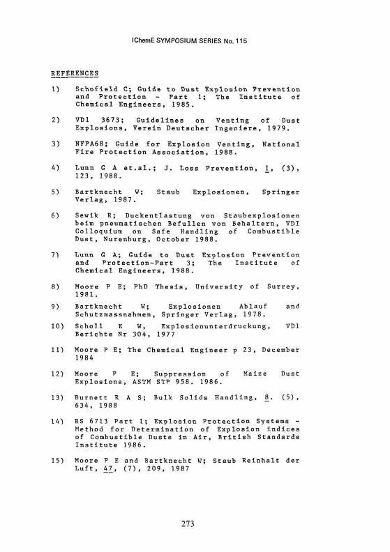
A typical proprietary rupture panel is shown in Figure 1 (a). It is a slotted thin stainless steel/PTFE/stainless steel sandwich, designed to fail at a specific overpressure - thus providing an unimpeded route for explosion relief. These types of circular or rectilinear rupture panels are particularly appropriate where the explosion is to be ducted from the plant component to a safe area. A proprietary "pop-out" panel is shown In Figure 1 (b). Tt comprises a low Inertia stainless steel
258
IChemE SYMPOSIUM SERIES No. 115
panel held in place by calibrated release catches. It is restrained by chains and, unlike the rupture panel, is essentially a reuseable device. The venting efficiency of "pop-out" panels is similar to that of rupture panels.
Thermally insulated versions of both rupture and "pop-out" panels are available. These would be used where condensate build-up on the cold surface of a standard vent closure could cause process difficulties. For the food industry vent closures with hygienic seals are available to ensure no biological contamination. Most proprietary explosion vent closures can be supplied with a "break wire" sensor to initiate plant shut-down and/or post explosion fire extinguishing measures as appropriate.
Vent panels leave the plant component with an opening to atmosphere after an explosion incident. The ingress of air can sustain a significant fire after a vented explosion in plant components such as silos and bag filters that have a high fire load. Post explosion fire extinguishing measures should be installed on such components. An alternative vent closure device, the explosion door or hinged panel, reduces this fire load. Explosion doors are particularly appropriate for process plant that operates under reduced oxygen, perhaps by feeding combustion gases back into the plant, or for processes involving either flammable gases, or gases with extreme odours. The explosion door is a less efficient vent than the rupture panel. It is designed to self close, thus resealing the plant after an explosion incident. Figure 2 shows a proprietary door that does not transmit any significant reaction forces to the plant component as it operates.
As an alternative to the passive explosion vent closures described above, in some applications an active explosion vent is more appropriate. This comprises an explosive catch fitted to an explosion door, or a glass bursting panel that is explosively opened when an incipient explosion is annunciated by some explosion detection device. One such active explosion panel is shown in Figure 3.
2.2 Design of Explosion Venting Measures
Explosion venting devices must be designed and installed such that they effectively relieve the explosion pressure from a plant component. The effectiveness of the explosion vent is dependant on a number of factors:
- free volume of component to be protected - V
259
IChemE SYMPOSIUM SERIES No. 115
explosion Intensity of the combustible dust: P - maximum explosion explosion rate constant. P - maximum explosion pressure, K
ot
- static opening pressure of the vent closure device - P .
stat - unimpeded surface area of the vent opening - F
inertia/venting efficiency of the vent closure device
- length and geometry of any duct used to direct the vented explosion to a safe area.
The vent closure must be located such that the explosion has an unimpeded passage to the vent opening. From the above parameters an estimation of the reduced (vented) explosion pressure, P ,, can be made by reference to an appropriate design code. Explosion protection by explosion relief venting demands that:
P , < P red s
where P is the pressure load corresponding to the minimum yield stress for the plant component. The plant component must be constrained such that it can withstand the transient reaction force P ,/F incident on the vent
red aperture.
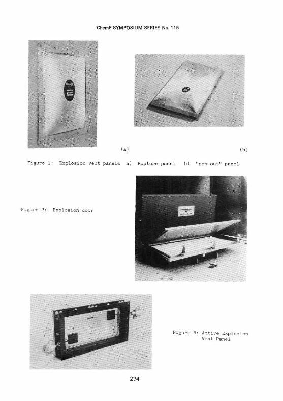
The accepted means of sizing explosion relief vents is based on a collection of published nomograms of the type shown in Figure 4. Selection of the nomograph appropriate to the vent opening pressure P enables the minimum vent area, F, to be determined for a plant component of volume V and dust of explosion intensity, K„ . These nomograms form the basis of UK(1), German (2) and U.S.(3) codes. Lunn (4) has recently extended these nomograms to account for dusts with low K (K < 50 bar m s ) and for vent closures with low opening pressures (P < 0.1 bar g). These nomograms are all based on turbulent hydrocarbon dust explosions with P = 1 0 bar. Barthnecht (5) has published alternative nomograms for P = 9 bar dusts, and Siwek (6) has established an alternative means of sizing vents for low turbulent pneumatic filling type operations. All of these codes refer to vent panels with a defined opening pressure, P . Explosion doors have a stated venting efficiency WE%. The explosion doors can be sized by reference to the same nomograms where
(Door) (Panel) WE
260
IChemE SYMPOSIUM SERIES No. 115
The use of a duct to direct an explosion away from a hazardous area (e.g. to outside of a building) has a significant detrimental influence on the venting efficiency. Typically the pressure load on a plant component will increase from say 0.2 bar to 0.4 bar for a straight duct of 3m length, and to 1.1 bar for a straight duct of 6m length. Lunn (7) has recently published a vary comprehensive guide which quantifies the influence of straight ducts, and ducts with one or two bends on the resultant pressure load of a plant component.
3. EXPLOSION SUPPRESSION
Explosion suppression is a procedure whereby the incipient explosion is detected and extinguished with a suitable suppressant before the explosion pressure exceeds the plant component pressure shock resistance. Thus, like explosion venting, the design criteria for explosion suppression requires that the reduced (suppressed) explosion pressure:
where P is the pressure load corresponding to the minimum yield stress of the plant component.
An explosion suppression system comprises explosion detector(s), explosion suppressor(s) and a central control unit. The detector senses the incipient explosion and triggers automatic high rate discharge explosion suppressors. The suppressant charge is discharged into the enveloping fireball to extinguish all combustion. Thus the explosion incident is completely contained within the plant component, and is suppressed before a significant pressure load or heat flash excursion occurs.
The suppressant discharged into the component renders the conditions within the plant inert for a time, thus ensuring that there is no re-ignition - provided that the plant is rapidly shut-down to reduce suppressant purging. In some cases it is necessary to install fast acting dampers across fans and/or blowers to attain this design requirement. After a suppressed explosion incident, it is usually necessary to clean down the plant, remove product contaminated with suppressant, and reinstate the suppression system before production can continue. Typically, down time of some 6-12 hours should be expected.
An explosion suppression system is an active system. Its effectiveness depends on the reliability of the installed components. Thus high quality hardware with assured reliability is a requirement for such measures. Nuisance activations will result if sufficient care has not been taken
261
IChemE SYMPOSIUM SERIES No. 115
at the design stage to ensure a significant margin of safety between detection pressure threshold and normal or abnormal process pressure excursions. Sensors must be of the highest reliability, tolerant to shock and vibration. Their preset pressure threshold must neither drift with time on the plant, nor as a result of process temperature excursions.
Explosion suppression hardware is normally bolted onto flanges or stub pipes that are welded into the plant component. Suppressors must be located to deploy suppressant into the explosible volume and the fixings must be designed to withstand the reaction force of the suppressor discharge, and to support the weight of the suppressors.
Explosion suppression is usually selected where it is either impractical or too costly to install explosion relief venting. It is particularly appropriate for plant components that are located in buildings and where the release of product could contaminate the environment if vented. For a large industrial process, the explosion suppression system would be divided into discrete zones. Each zone would have a dedicated control unit, and would be designed to suppress and contain the explosion incident within its zone boundaries.
3.1 Types of Explosion Suppression Measures
For dust explosions, explosion detection is normally by threshold membrane detectors of the type shown in Figure 5. Such detectors provide an electrical contact when the pressure load exceeds a preset value. It is normal practice to install two such detectors mutually at 90 , and to require that both detectors operate to activate the explosion suppressors. This procedure essentially eliminates nuisance activations arising from shock, vibration or mechanical damage of the detector membrane. In process plant that operates under positive pressure it is advisable to fit an overpressure sensor adjacent to the explosion detectors. The purpose of this overpressure sensor is to trip out the blower if the plant pressure begins to rise, for example, because of a blockage in a downstream duct. In some circumstances a "rate of rise" pressure sensor, or a more sophisticated analogue pressure sensor with electronic signal processing may be appropriate, but optical sensors are unlikely to be applicable to most particulate explosion hazards.
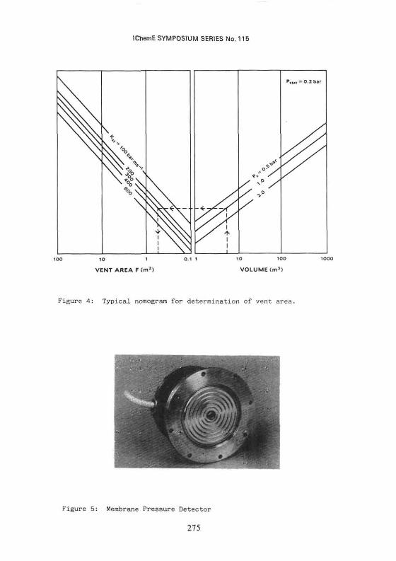
There is a wide range of explosion suppression hardware available to the application engineer. Selection of the most appropriate hardware and configuration for a particular application, and effective deployment of the explosion suppressant will effect system performance. Figure 6a shows a range of hemispherical explosion suppressors. This type of explosion suppressor is
262
IChemE SYMPOSIUM SERIES No. 115
mounted inside the plant component and can discharge liquid suppressant . within 2ms of detection at a velocity 200 m s An explosive charge petals the scored frangible dome of the hemispherical suppressor, thus thrusting suppressant at the enveloping fireball. This type of suppressor is particularly suited for ducts, elevator legs and small volume plant components. They are unsuited to erosive or high temperature environments.
Single exit and dual exit explosion suppressors are shown in Figure 6b. These suppressors use a high speed valve to release their stored charge of suppressant, which Is expelled under pressure of dry nitrogen through a flexible hose or other plant connector to a dispersion nozzle mounted on the plant component. Typically, such suppressors use non-explosive actuators but have only a limited rate of suppressant delivery. They would be deployed against the less intense dust explosion hazards, or for rapid fire extinguishing or advance inerting measures. For the more violent dust explosions, high rate discharge suppressors (HRDs) of the type shown in Figure 6c are more appropriate. These suppressors use a 75 mm diameter or a 125 mm diameter explosive valve to release their charge of suppressant, typically 4 kg, 16 kg, or 35 kg into the plant component at 100 kg s Such suppressors are directly mounted onto the plant component. The high propelling agent pressure, typically 60 bar dry nitrogen, expels the suppressant through either fixed or telescopic nozzles into the plant component. This type of explosion suppressor is suited to all applications. High plant temperature (maximum 250 C) and hygienic plant seal versions are available. A typical telescopic nozzle arrangement - see Figure 7 -ensures that the suppressor nozzle does not intrude in the normal flow conditions of the process plant.
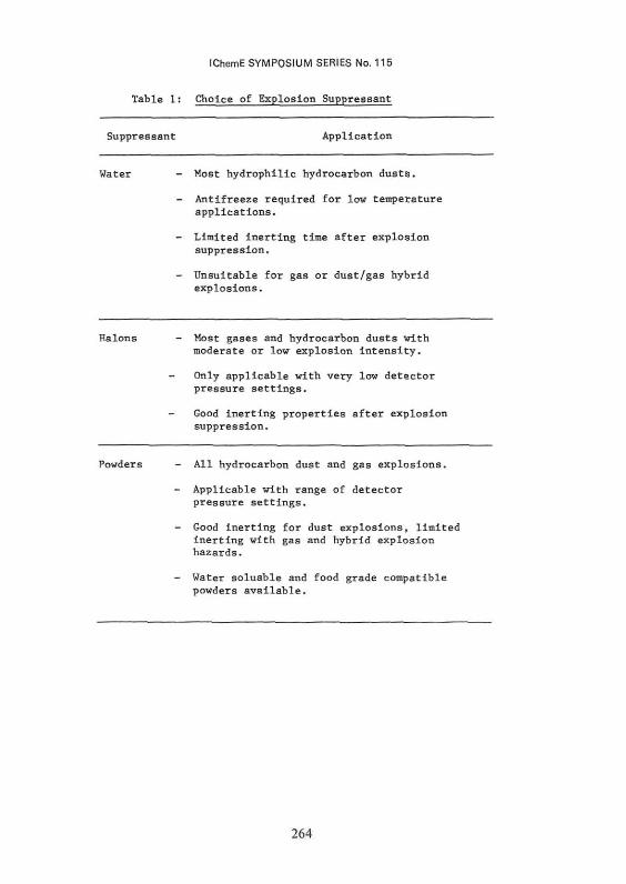
Explosion suppression systems are available with alternative explosion suppressants. Table 1 summarises the commonly available suppressants, and comments on their application. In practice, powder suppressants have a much greater range of application against dust explosions than other suppressant agents.
263
IChemE SYMPOSIUM SERIES No. 115
Table 1: Choice of Explosion Suppressant
Suppressant Application
Water - Most hydrophilic hydrocarbon dusts.
- Antifreeze required for low temperature applications.
- Limited inertlng time after explosion suppression.
- Unsuitable for gas or dust/gas hybrid explosions.
Halons - Most gases and hydrocarbon dusts with moderate or low explosion Intensity.
- Only applicable with very low detector pressure settings.
Good inertlng properties after explosion suppression.
Powders - All hydrocarbon dust and gas explosions.
- Applicable with range of detector pressure settings.
- Good inertlng for dust explosions, limited inertlng with gas and hybrid explosion hazards.
- Water soluable and food grade compatible powders available.
264
IChemE SYMPOSIUM SERIES No. 115
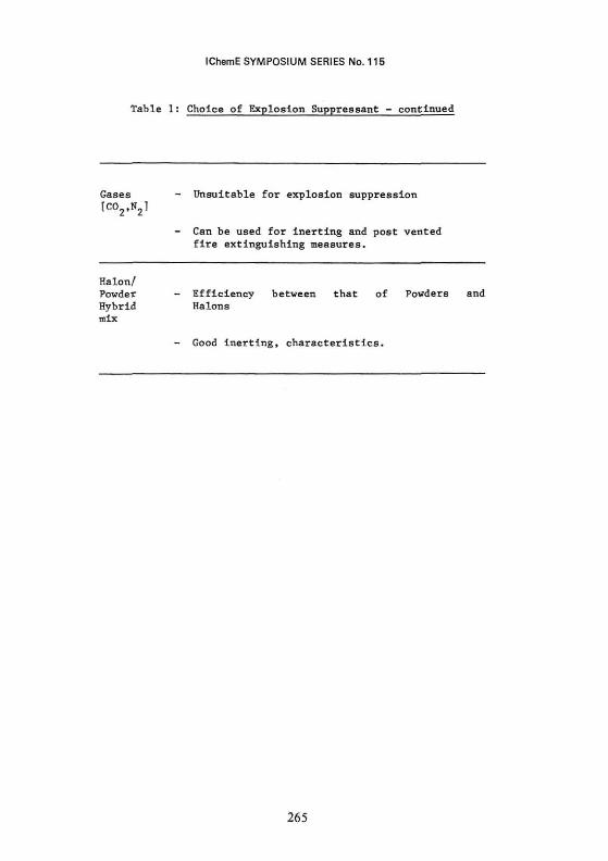
Table 1: Choice of Explosion Suppressant - continued
Gases - Unsuitable for explosion suppression [C02,N21
- Can be used for inerting and post vented fire extinguishing measures.
Halon/ Powder - Efficiency between that of Powders and Hybrid Halons mix
- Good inerting, characteristics.
265
IChemE SYMPOSIUM SERIES No. 115
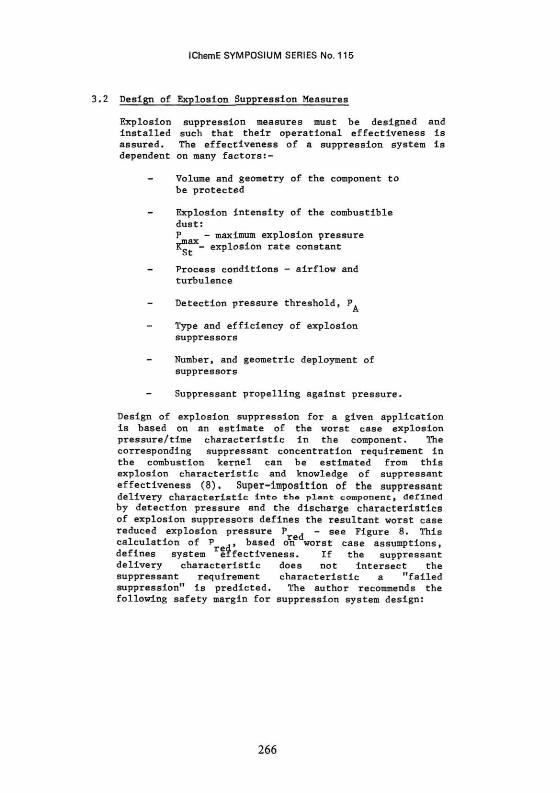
3.2 Design of Explosion Suppression Measures
Explosion suppression measures must be designed and installed such that their operational effectiveness is assured. The effectiveness of a suppression system is dependent on many factors:-
Volume and geometry of the component to be protected
- Explosion Intensity of the combustible dust: P - maximum explosion p ressure „max . , KT - explosion rate constant ot
- Process conditions - airflow and turbulence
Detection pressure threshold, P. r A
Type and efficiency of explosion suppressors
Number, and geometric deployment of suppressors
Suppressant propelling against pressure.
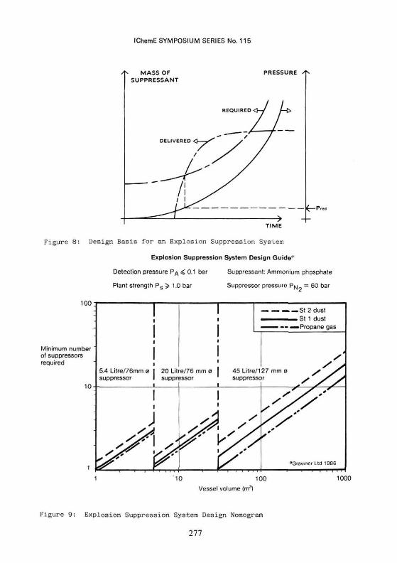
Design of explosion suppression for a given application is based on an estimate of the worst case explosion pressure/time characteristic in the component. The corresponding suppressant concentration requirement in the combustion kernel can be estimated from this explosion characteristic and knowledge of suppressant effectiveness (8). Super-imposition of the suppressant delivery characteristic into the plant component, defined by detection pressure and the discharge characteristics of explosion suppressors defines the resultant worst case reduced explosion pressure P . - see Figure 8. This calculation of P ,, based on worst case assumptions, defines system effectiveness. If the suppressant delivery characteristic does not intersect the suppressant requirement characteristic a "failed suppression" is predicted. The author recommends the following safety margin for suppression system design:
266
IChemE SYMPOSIUM SERIES No. 115
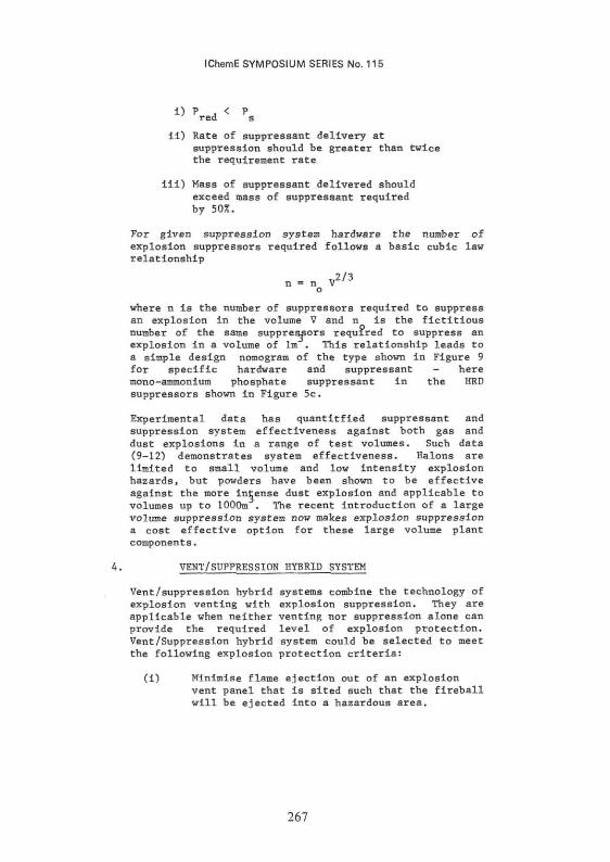
1) P , < P r e d s
ii) Rate of suppressant delivery at suppression should be greater than twice the requirement rate
iii) Mass of suppressant delivered should exceed mass of suppressant required by 50%.
For given suppression system hardware the number of explosion suppressors required follows a basic cubic law relationship
2/3 n = n V " J
o
where n is the number of suppressors required to suppress an explosion in the volume V and n is the fictitious number of the same suppressors required to suppress an explosion in a volume of lm . This relationship leads to a simple design nomogram of the type shown in Figure 9 for specific hardware and suppressant - here mono-ammonium phosphate suppressant in the HRD suppressors shown in Figure 5c.
Experimental data has quantitfied suppressant and suppression system effectiveness against both gas and dust explosions in a range of test volumes. Such data (9-12) demonstrates system effectiveness. Halons are limited to small volume and low intensity explosion hazards, but powders have been shown to be effective against the more intense dust explosion and applicable to volumes up to 1000m . The recent introduction of a large volume suppression system now makes explosion suppression a cost effective option for these large volume plant components.
4. VENT/SUPPRESSION HYBRID SYSTEM
Vent/suppression hybrid systems combine the technology of explosion venting with explosion suppression. They are applicable when neither venting nor suppression alone can provide the required level of explosion protection. Vent/Suppression hybrid system could be selected to meet the following explosion protection criteria:
(i) Minimise flame ejection out of an explosion vent panel that is sited such that the fireball will be ejected into a hazardous area.
267
IChemE SYMPOSIUM SERIES No. 115
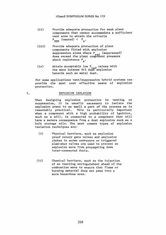
(11) Provide adequate protection for weak plant components that cannot accommodate a sufficient vent area to attain the criteria PRED (v6nted) < V
(ill) Provide adequate protection of plant components fitted with explosion suppression alone where P . (suppressed) does exceed the plant component pressure shock resistance P ,
(iv) Attain acceptably low P . values with the more intense St3 dust explosion hazards such as metal dust.
For some applications vent/suppression hybrid systems can provide the most cost effective means of explosion protection.
5. EXPLOSION ISOLATION
When designing explosion protection by venting or suppression, it is usually necessary to isolate the explosion event to as small a part of the process as is reasonably practical. This is particularly important when a component with a high probability of ignition, such as a mill, is connected to a component that will have a severe consequence from a dust explosion such as a bulk storage silo. The most common types of explosion Isolation techniques are:
(i) Physical barriers, such as explosion proof rotary gate valves and explosion chokes in screw conveyors or triggered slam-shut valves are used to prevent an explosion wave from propagating down Inter-connected ducts.
(ii) Chemical barriers, such as the injection of an inerting extinguishant ahead of the combustion wave to ensure that flame or burning material does not pass into a more hazardous area.
268
IChemE SYMPOSIUM SERIES No. 115
6. EXPLOSION PROTECTION - THE CHOICE
For most applications there is no one unique solution for a particular explosion hazard. The choice between explosion venting and explosion suppression will depend on both technical and economic factors. In practice, it would be usual to select the most cost effective means of providing adequate explosion protection. This choice may be influenced by a corporate policy, perhaps influenced by employee relations, whereby a fireball release is judged to be unacceptable, even though such release is not hazardous.
In most applications, it would be usual to assess the practicality and cost consequence of installing an explosion venting system. Determination of the vent area requirements, selection of the most appropriate vent closure, estimating the cost of installation of the vent device and any vent ducting, together with any requirement for plant strengthening to withstand the pressure load P , and the reaction force P ,/P can lead
red red to an estimate or the cost of such a system. To this cost must be added the requirement for post vented fire extinguishing and any explosion isolation requirement such as slam-shut valves and plant shut down.
The cost of explosion protection by venting can then be compared with the cost of purchase, installation and life cycle maintenance of an explosion suppression system. In most cases suppression is selected where it is either impractical or expensive to install explosion vents, or where venting is not an appropriate safety measure. Thus practical constraints associated with the plant component, its location and the type of product being processed would lead to the selection of explosion suppression, rather than explosion venting.
In most process plants, the consequence of such considerations is likely to result in a mixture of venting, for those plant components that can be readily vented, and of suppression for other components where venting proves to be either impractical, inappropriate or very expensive to implement.
269
IChemE SYMPOSIUM SERIES No. 115
CASE STUDIES
7 . Case S tudy 1 .
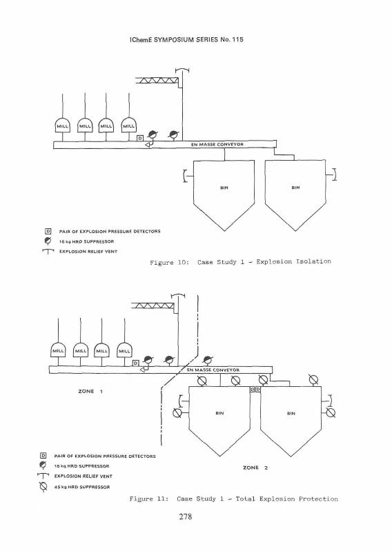
Part of an animal feed milling process is shown schematically in Figure 10. Explosion protection was by explosion relief venting using explosion doors fitted to the 6m long bypass chute on the en masse conveyor, and to each of the bins. The vent areas installed on the bins were the largest that could be practically fitted such that the explosion could be ducted through < 3m long ducts to a safe discharge point. A survey of the plant identified the following features:
(i) The ignition probability was greatest in the vicinity of the mills where the product was being mechanically worked.
(ii) The explosion consequence was greatest in the bins, particularly if a bin was nearly empty, since the vent area installed was inadequate, and the bin was mounted inside a large building where the prospect of a secondary dust explosion existed if a bin were to rupture.
(iii) An explosion incident in any one bin could communicate to the adjacent bin via the en masse conveyor, but explosion propagation via the bin outlet through the screw conveyor was unlikely.
The most immediate safety enhancement to this process is to establish effective explosion isolation between the mills and the bins. This was achieved by installing an explosion isolation extinguishing barrier on the en masse conveyor between the mills and the bins. Detection of an explosion propagating down the conveyor results in the suppression of the combustion wave before it reaches the bins. This system was installed as a first step to improve explosion safety. Since installation, the system has operated twice, on both occasions preventing known dust explosion events in the mills from propagating into the bins.
Since the explosion vents fitted to the bins are undersized it is necessary to increase the vent areas, such that a worst case explosion incident in any bin is protected. The cost consequence of installing explosion vents, using proprietary panels and of both ducting the vented explosion to a safe area and increasing the bin
270
IChemE SYMPOSIUM SERIES No. 115
pressure shock resistance was contrasted with the alternative of fitting explosion suppression to these bins. For this application explosion suppression turned out to be the most economic option, and this safety measure has been selected to protect the two bins, thus providing a full explosion protection safety package - as shown in Figure 11.
7.2 Case Study 2. (reference 13)
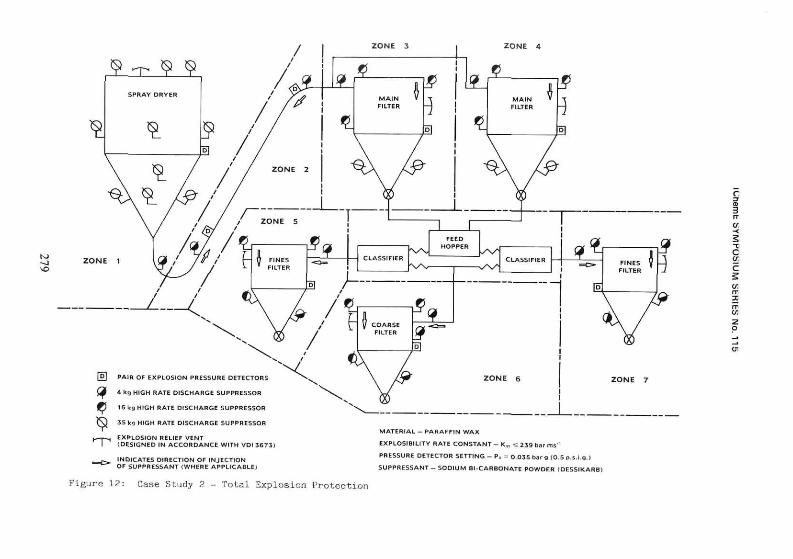
A large spray drying plant producing a wax product had suffered a history of fire and explosion incidents. Explosion relief had been installed on several components - but in one major incident these had only partially relieved the force of the explosion and extensive damage occurred. The explosion vents installed were based on the belief that the dust had a moderate explosibility quotient as adjudged by Hartmann explosibility data. A re-evaluation of the product in accordance with BS6713 (14) proved this to be wrong. The material was an Intense dust with a very low minimum ignition energy. Thus ignition by electrostatic discharge was a prospect with this product. These results explained the ineffectiveness of the installed venting measures and Indentified that ignition must be anticipated at all locations in the process. Thus a complete re-evaluation of the plant was undertaken. Since the installed venting was into buildings, which Is not an acceptable practice, it proved appropriate to protect this process by explosion suppression.
Figure 12 indicates the hazardous section of plant and the various protection methods incorporated. Some of the component volumes ar* very large - spray dryer (320 m ) ; main filters (110 m ) - and in the past this has meant that explosion relief venting was the only practicable solution. However, a new suppressor configuration recently introduced by Graviner has extended the limit of explosion suppression to volumes of 1000m (15). Ten of these new suppressors, each filled with 35kg of powder suppressant, were needed to protect the volume of the dryer. The geometry of the main filters and the obstruction imposed by the filter bags meant that a sufficient number of suppressors were required to introduce suppressant into all the explosible voids - two 35kg suppressors and three 16kg suppressors sufficed. In order to cater for the low plant strengths involved and the increased violence of the potential explosion, a combination of explosion relief venting and explosion suppression was selected. This hybrid protection system relies on the suppression system to extinguish the explosion, and the vents to further relieve any explosion
271
IChemE SYMPOSIUM SERIES No. 115
overpressure - achieving a very low final pressure of 0.05 bar in the spray dryer. Because the explosion will have been extinguished, flame will be ejected through the vents. In fact, one or two suppressors on each component were arranged to discharge their contents directly across the vent apertures, to ensure that virtually all flame is extinguished.
The action of explosion suppression within components will extinguish burning material within the plant component. However, the ducting between components will contain combustible products and thus provide a path for the flame to travel ahead of the explosion and so on to the next part of the plant. Rotary gate valves, which can be stopped on detection of an explosion, were already installed on the outlets of all the filters - these form an effective mechanical barrier to burning material -however, the inlet ducts need some form of protection. Additional suppressors were arranged to discharge their contents along the ducts, directed into the filters, thus forming chemical barriers preventing the propagation of an explosion. The duct between the drier and the main filters need a total of three suppressors, because of its size and length.
The suppressors for this plant were filled with a water soluble powder suppressant Dessikarb,such that, following an activation, suppressant could be easily removed from the process and separated from the non-soluble process material - thus ensuring minimal loss of product.
272
IChemE SYMPOSIUM SERIES No. 115
REFERENCES
1) Schofleld C; Guide to Dust Explosion Prevention and Protection - Part 1; The Institute of Chemical Engineers, 1985.
2) VD1 3673; Guidelines on Venting of Dust Explosions, Verein Deutscher Ingeniere, 1979.
3) NFPA68; Guide for Explosion Venting, National Fire Protection Association, 1988.
4) Lunn G A et.al.; J. Loss Prevention, 1_, (3), 123, 1988.
5) Bartknecht W; Staub Explosionen, Springer Verlag, 1987.
6) Sewik R; Duckentlastung von Staubexplosionen beim pneumatischen Befullen von Behaltern, VDT Colloquium on Safe Handling of Combustible Dust, Nurenburg, October 1988.
7) Lunn G A; Guide to Dust Explosion Prevention and Protection-Part 3; The Institute of Chemical Engineers, 1988.
8) Moore P E; PhD Thesis, University of Surrey, 1981 .
9) Bartknecht W; Explosionen Ablauf and Schutzmassnahmen, Springer Verlag, 1978.
10) Scholl E W, Explosionunterdruckung, VDI Berichte Nr 304, 1977
11) Moore P E; The Chemical Engineer p 23, December 1984
12) Moore P E; Suppression of Maize Dust Explosions, ASTM STP 958. 1986.
13) Burnett R A S; Bulk Solids Handling, £. (5), 634, 1988
14) BS 6713 Part 1; Explosion Protection Systems -Method for Determination of Explosion indices of Combustible Dusts in Air, British Standards Institute 1986.
15) Moore P E and Bartknecht W; Staub Reinhalt der Luft, 47, (7), 209, 1987
273
IChemE SYMPOSIUM SERIES No. 115
(a) (b)
Figure 1: Explosion vent panels a) Rupture panel b) "pop-out" panel
Figure 2: Explosion door
Figure 3: Active Explosion Vent Panel
274
IChemE SYMPOSIUM SERIES No. 115
VENT AREA F (m 2 )
10 100
VOLUME <mJ)
Figure A-. Typical nomogram for determination of vent area.
Figure 5: Membrane Pressure Detector
275
IChemE SYMPOSIUM SERIES No. 115
Figure 6: Explosion Suppressors
(c)
Figure 7: Telescopic Nozzel
276
IChemE SYMPOSIUM SERIES No. 115
*-P-
figure 8: Design Basis for an Explosion Suppression System
Explosion Suppression System Design Guide"
Detection pressure P^ < 0.1 bar Suppressant: Ammonium phosphate
Plant strength Ps ̂ 1.0 bar Suppressor pressure P^ = 60 bar
100
Minimum number of suppressors required
5.4 Litre/76mm a suppressor
.St 2 dust i St 1 dust • Propane gas
/ 20 Litre/76 mm 0 I 45 Litre/127 mm o / suppressor suppressor *
1000
Vessel volume (m3
Figure 9: Explosion Suppression System Design Nomogram
277
IChemE SYMPOSIUM SERIES No. 115
[o\ PAIR OF EXPLOSION PRESSURE DETECTORS
^ 5 16 kg HRO SUPPRESSOR
^ - p 1 EXPLOSION RELIEF VENT
Figure 10: Case Study 1 - Explosion Isolation
AA/WI
MILL MILL [MILL MILL
m $ - ,S EN MASSE CONVEYOR
|2ll2| 3.
-]
f o l PAIR OF EXPLOSION PRESSURE DETECTORS
TJ 16 Its HRO SUPPRESSOR Z O N E 2
• " P * EXPLOSION RELIEF VENT
( \ J 45 kg HRD SUPPRESSOR
Figure 11: Case Study 1 - Total Explosion Protection
278
lUie
mt bY
MP
OS
lUM
Stm
ts N
o. lib
279