
Electron Diffraction Applications Using the PDF-4+ Relational Database.
Industrial applications of electron accelerators
M.R. Cleland Ion Beam Applications, Edgewood, NY 11717, USA
Abstract This paper addresses the industrial applications of electron accelerators for modifying the physical, chemical or biological properties of materials and commercial products by treatment with ionizing radiation. Many beneficial effects can be obtained with these methods, which are known as radiation processing. The earliest practical applications occurred during the 1950s, and the business of radiation processing has been expanding since that time. The most prevalent applications are the modification of many different plastic and rubber products and the sterilization of single-use medical devices. Emerging applications are the pasteurization and preservation of foods and the treatment of toxic industrial wastes. Industrial accelerators can now provide electron energies greater than 10 MeV and average beam powers as high as 700 kW. The availability of high-energy, high-power electron beams is stimulating interest in the use of X-rays (bremsstrahlung) as an alternative to gamma rays from radioactive nuclides.
1 Introduction Radiation processing can be defined as the treatment of materials and products with radiation or ionizing energy to change their physical, chemical or biological characteristics, to increase their usefulness and value, or to reduce their impact on the environment. Accelerated electrons, X-rays (bremsstrahlung) emitted by energetic electrons, and gamma rays emitted by radioactive nuclides are suitable energy sources. These are all capable of ejecting atomic electrons, which can then ionize other atoms in a cascade of collisions. So they can produce similar molecular effects. The choice of energy source is usually based on practical considerations, such as absorbed dose, dose uniformity (max/min) ratio, material thickness, density and configuration, processing rate, capital and operating costs.
In the case of electron beam (EB) processing, the incident electron energy determines the maximum material thickness, and the electron beam current and power determine the maximum processing rate. In the case of X-ray processing, the emitted power increases with the electron energy and beam power. For high throughput industrial processes, the capital costs and operating costs of an irradiation facility are competitive with more conventional treatment methods.
Successful irradiation processes provide significant advantages in comparison to typical thermal and chemical processes, such as higher throughput rates, reduced energy consumption, less environmental pollution, more precise control over the process and the production of products with superior qualities. In some applications, radiation processing can produce unique effects that cannot be duplicated by other means.
Radiation processing was introduced more than fifty years ago, and many useful applications have since been developed. The most important commercial applications involve modifying a variety of plastic and rubber products, and sterilizing medical devices and consumer items. Emerging applications are pasteurizing and preserving foods, and reducing environmental pollution.
383
2 Basic concepts of radiation processing
2.1 Absorbed dose definition
The most important specification for any irradiation process is the absorbed dose. The quantitative effects of the process are related to this factor. Absorbed dose is proportional to the ionizing energy delivered per unit mass of material. The international unit of dose is the gray (Gy), which is defined as the absorption of one joule per kilogram (J/kg) [1]. A more convenient unit for most radiation processing applications is the kilogray (kJ/kg or J/g). An older unit is the rad, which is defined as the absorption of 100 ergs per gram or 10–5 joules per gram. So, 100 rads is equivalent to 10–3 joules per gram or 1 joule per kilogram or 1 gray. The rad unit is now obsolete, but many commercial processes are still specified in rads, kilorads or megarads.
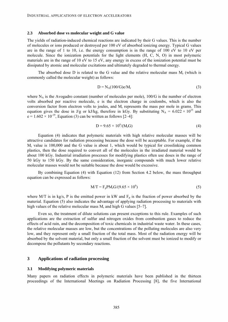
Absorbed dose requirements for various industrial processes cover a wide range, from 0.1 kGy to more than 1000 kGy, as indicated by the applications listed in Table 1. Most of these processes need less than 100 kGy, some need less than 10 kGy and some need even less than 1 kGy.
Table 1: Absorbed dose requirements for various industrial processes
Sprout inhibiting 0.1–0.2 kGy Sterilization 10–30 kGy
Insect disinfesting 0.3–0.5 kGy Polymerization 20–50 kGy
Parasite control 0.3–0.5 kGy Grafting monomers 20–50 kGy
Delay of ripening 0.5–1.0 kGy Crosslinking polymers 50–150 kGy
Fungi control 1.5–3.0 kGy Degrading polymers 500–1500 kGy
Bacteria control 1.5–3.0 kGy Coloring gemstones >>> 1500 kGy
2.2 Temperature rise vs absorbed dose
If the energy transfers from chemical reactions are negligible, then the adiabatic temperature rise (ΔT) from the absorption of thermal energy per unit mass (H) is given by the following equation:
ΔT = H/c (1)
where ΔT is in ºC, H is in J/g and c is the thermal capacity in J/g ºC. Similarly, the adiabatic temperature rise from the absorption of ionizing energy is given by:
ΔT = D(ave)/c (2)
where D(ave) is the average dose in kGy (kJ/kg or J/g), and ΔT and c are the same as in Equation (1).
The thermal capacity of water is 4.19 J/g ºC, so the adiabatic temperature rise would be 0.24 ºC with an average absorbed dose of 1.0 kGy. Most other materials have lower thermal capacities and higher rises in temperature with the same dose. For example, the thermal capacity of polyethylene is 2.3, polytetrafluoroethylene is 1.05, aluminum is 0.90, copper is 0.38 and tantalum is 0.15 J/g ºC. Typical doses for pasteurizing fresh meat are in the range of 2 to 3 kGy. Since this material is about 80% water, the adiabatic temperature rise would be in the range of 0.5 to 0.7 ºC. On the other hand, when electrical wire receives a typical dose of 100 kGy to crosslink the insulation, the temperature rise of the copper conductor could be as high as 260 ºC. This excessive temperature rise can be reduced by passing the wire many times back and forth through the electron beam to allow most of the heat to dissipate in the air and in the underbeam wire handling fixture.
M.R. CLELAND
384
2.3 Absorbed dose vs molecular weight and G value
The yields of radiation-induced chemical reactions are indicated by their G values. This is the number of molecules or ions produced or destroyed per 100 eV of absorbed ionizing energy. Typical G values are in the range of 1 to 10, i.e. the energy consumption is in the range of 100 eV to 10 eV per molecule. Since the ionization potentials for the light elements (H, C, N, O) in most polymeric materials are in the range of 10 eV to 15 eV, any energy in excess of the ionization potential must be dissipated by atomic and molecular excitations and ultimately degraded to thermal energy.
The absorbed dose D is related to the G value and the relative molecular mass Mr (which is commonly called the molecular weight) as follows:
D = NA(100/G)e/Mr (3)
where NA is the Avogadro constant (number of molecules per mole), 100/G is the number of electron volts absorbed per reactive molecule, e is the electron charge in coulombs, which is also the conversion factor from electron volts to joules, and Mr represents the mass per mole in grams. This equation gives the dose in J/g or kJ/kg, therefore in kGy. By substituting NA = 6.022 × 10²³ and e = 1.602 × 10⁻¹⁹, Equation (3) can be written as follows [2–4]:
D = 9.65 × 10⁶/(MrG) (4)
Equation (4) indicates that polymeric materials with high relative molecular masses will be attractive candidates for radiation processing because the dose will be acceptable. For example, if the Mr value is 100,000 and the G value is about 1, which would be typical for crosslinking common plastics, then the dose required to convert all of the molecules in the irradiated material would be about 100 kGy. Industrial irradiation processes for modifying plastics often use doses in the range of 50 kGy to 150 kGy. By the same consideration, inorganic compounds with much lower relative molecular masses would not be suitable because the dose would be excessive.
By combining Equation (4) with Equation (12) from Section 4.2 below, the mass throughput equation can be expressed as follows:
M/T = FpPMrG/(9.65 × 106) (5)
where M/T is in kg/s, P is the emitted power in kW and Fp is the fraction of power absorbed by the material. Equation (5) also indicates the advantage of applying radiation processing to materials with high values of the relative molecular mass Mr and high G values [5–7].
Even so, the treatment of dilute solutions can present exceptions to this rule. Examples of such applications are the extraction of sulfur and nitrogen oxides from combustion gases to reduce the effects of acid rain, and the decomposition of toxic chemicals in industrial waste water. In these cases, the relative molecular masses are low, but the concentrations of the polluting molecules are also very low, and they represent only a small fraction of the total mass. Most of the radiation energy will be absorbed by the solvent material, but only a small fraction of the solvent must be ionized to modify or decompose the pollutants by secondary reactions.
3 Applications of radiation processing
3.1 Modifying polymeric materials
Many papers on radiation effects in polymeric materials have been published in the thirteen proceedings of the International Meetings on Radiation Processing [8], the five International
INDUSTRIAL APPLICATIONS OF ELECTRON ACCELERATORS
385
Conferences on Ionizing Radiation and Polymers [9] and the two Pacifichem Conference Sessions on Polymer Radiation Chemistry [10]. In addition to References [2] and [4], other books have also been published on radiation chemistry and the practical applications of radiation processing. Several of these are listed in References [11-18]. The Radiation Laboratory of the University of Notre Dame in South Bend, Indiana, maintains an on-line bibliography of papers on basic and applied radiation chemistry [19]. A recent review of the commercial aspects of radiation processing as applied to polymeric materials and products has been presented in Reference [20].
3.1.1 Polymerizing
Low-energy (75 keV to 300 keV) electron accelerators are used to cure (polymerize and crosslink) coatings, adhesives and inks on paper, plastic and metal substrates. Such materials consist of oligomers (polymers with low molecular weights) and monomers to provide fluidity before curing. This technique avoids the use of volatile solvents, thereby helping to reduce air pollution. Acrylated urethane polyesters, acrylated epoxies and polyethers are suitable oligomers, and trimethylolpropane triacrylate (TMPTA) is a suitable monomer. Polymerizations are chain reactions which produce high relative molecular masses with comparatively low doses of less than 50 kGy. Line speeds up to 1500 m/min can be achieved at 10 kGy [21, 22].
High-energy (up to 10 MeV) accelerators are used to cure fiber-reinforced composite materials. In comparison to heat curing, the processing time and cost can be reduced with electron beam or X-ray curing. Acrylated epoxies with carbon fibers are suitable materials. Higher doses (150 kGy to 250 kGy) are needed to obtain a combination of polymerization and crosslinking [23-25]. This is an emerging application for electron beam and X-ray processing. Composite parts now being used in automobiles and aircraft are mainly cured with heat, but radiation curing offers several advantages.
3.1.2 Grafting
Graft copolymerization of monomers with preformed polymers can be used to modify the properties of their surfaces [4]. This can be done with common polymers such as polyethylene, polypropylene and some fluoropolymers. Plastic films, membranes, fibers and textiles are suitable products. Styrene, acrylic acid, 4-vinylpyridine and N-vinylpyrrolidone can be grafted onto polytetrafluoroethylene (Teflon®) [26]. Other combinations are styrene on cellulose, vinylpyridines on wool and p-nitrostyrene on polyethylene, polyvinyl chloride and polypropylene [27]. Hydrophilic properties can be added to hydrophobic polymers to make permselective membranes [28]. Ion exchange membranes, fuel cell and battery separator films, permeation separation membranes, promotion of surface adhesion, chelating fibers for sea-water treatment and for recovering some precious metals from sea-water are other possibilities [29]. Grafting can also improve the biocompatibility of polymers for medical applications [30]. Dose requirements are similar to those for curing coatings.
3.1.3 Crosslinking
Radiation crosslinking began more than 50 years ago when it was discovered that polyethylene (PE) could be crosslinked in this way [2]. This is still the most important irradiated material because it is used in many products and it is relatively inexpensive. Crosslinking is the most widely used effect of polymer irradiation because it can improve the mechanical, thermal and chemical qualities of preformed products as well as bulk materials [13–18].
Both crosslinking and degradation by chain scissioning can occur during polymer irradiation, but one or the other effect may be predominant. Typical G-values for crosslinking G(X) and for chain scissioning G(S) are given in Table 2 for some pure polymeric materials [31]. Crosslinking is favored for those materials with a G(S)/G(X) ratio below 1.0. For example, the G(S) values for both low-density and high-density polyethylene are about half of their G(X) values. Natural rubber crosslinks readily because its G(S) value is very low. Polypropylene and polymethylmethacrylate (PMMA) are
M.R. CLELAND
386

not especially suitable for radiation crosslinking because their G(X) values are relatively low and their G(S)/G(X) ratios are greater than 1.0. Polytetrafluoroethylene (PTFE) and butyl rubber are unsuitable for radiation crosslinking because their G(S) values are too high. Typical polymers are classified in Table 3 according to their tendencies for crosslinking or scissioning.
Crosslinking doses are usually in the range from 50 to 150 kGy. Multifunctional monomers can be mixed with the polymer to increase the G(X) value and reduce the dose requirement. Antioxidants, UV stabilizers and flame retardant compounds can be added to improve the performance of the material for particular applications. Such additives may inhibit the crosslinking effect, so the properties of commercial materials are usually different from the pure polymers.
Table 2: Typical G(X) and G(S) values for polymers at room temperature without oxygen
Polymer G(X) G(S) Polymer G(X) G(S) Natural rubber 1.3–1.5 0.1–0.2 PTFE 0.1–0.3 3.0–5.0 Polyethylene 0.3–1.3 0.4–0.5 Butyl rubber < 0.5 2.9–3.7 Polypropylene 0.3–1.1 0.3–1.8 PMMA < 0.5 1.1–1.7
Table 3: Effects of ionizing radiation in typical polymers
Mainly crosslinking Mainly scissioning Polyethylene Polyisobutylene Polyacrylates Polymethacrylates Polyvinyl chloride Polymethylstyrene Polysiloxanes Polymethacrylamides Polyamides Polyvinylidene chloride Polystyrene Polytetrafluoroethylene Polyacrylamides Polypropylene ether Ethylene vinylacetate Cellulose
3.1.3.1 Insulated wire and cable
One of the first commercial applications of radiation crosslinking was the improvement of the insulation on electrical wires and the jackets on multi-conductor cables. Products of this type were introduced during the 1950s by the Raychem Corporation (since acquired by Tyco Electronics), and many wire manufacturers are now using this method to produce high-performance wire for aircraft and automobiles.
Polyethylene, polyvinylchloride, ethylene-propylene rubber, polyvinylidene fluoride and ethylene tetrafluoroethylene copolymer are some of the materials used in this application. Increased tolerance to overloaded conductors and high temperature environments, fire retardation, increased abrasion resistance, increased tensile strength, reduction in cold flow and increased resistance to solvents and corrosive chemicals are product improvements obtainable by this method [32–34].
3.1.3.2 Heat-shrinkable plastic tubing and film
Radiation crosslinking stabilizes the initial dimensions of products and imparts the so-called “memory” effect. Crosslinking occurs mainly in the amorphous zones of polyethylene, but the crystalline zones determine the stiffness of the material. The crosslinked material becomes elastic when heated above the melting temperature of the crystalline zones, which is approximately 100 ºC. The product can then be expanded or stretched to several times its original size. It maintains the larger dimension when cooled, but it contracts to its original size when heated again. Examples of
INDUSTRIAL APPLICATIONS OF ELECTRON ACCELERATORS
387

commercial products using this effect are encapsulations for electronic components, jackets for multi-conductor cables, exterior telephone cable connectors and food packaging films [35, 36].
3.1.3.3 Automobile tires
Several components of an automobile tire, such as the innerliner, the chafer strip, the sidewall, the body and tread plies, and the fabric or steel-reinforced belt, may be given a low dose of electron beam radiation before the tire is assembled. This partial radiation crosslinking stabilizes their thicknesses when the final chemical curing is done in a heated mold. Precuring also avoids migration of the steel belt through its supporting material. This dimensional stabilization produces a higher quality tire with more uniform thickness and better balance. Therefore, the tire can be made thinner to save material, reduce cost and reduce frictional heating at high speed. Materials are usually isoprene and diene elastomers with doses in the range of 30 to 50 kGy [13, 14, 37].
3.1.3.4 Plastic pipe
Concrete floors can be heated by circulating hot water through crosslinked polyethylene pipe embedded in the concrete. Such plastic pipe also has other applications. A composite pipe is made with a middle layer of thin aluminum, which withstands the water pressure, an inner plastic layer to avoid contact with the aluminum layer, and an outer plastic layer for abrasion resistance. The inner and outer layers are irradiated simultaneously with high-energy electrons.
3.1.3.5 Plastic foam
Plastic foam can be made by mixing a thermally unstable substance with a polymer and then heating the mixture to melt the polymer and decompose the additive. The evolved gas forms bubbles in the polymer. Azodicarbonamide can be used as the foaming additive. Polyethylene, ethylene vinylacetate copolymer and polypropylene can be used as the polymeric material. The expansion process is more easily controlled with crosslinked material. Foamed gaskets, coaxial cable insulation, coated tapes, helmet liners, athletic safety pads, bra cups, floor backing and automobile seat padding are typical applications [38, 39].
3.1.3.6 Hydrogels
Hydrogels will swell in water and hold more than 20% of water within their molecular structure, yet they will not dissolve in water. These kinds of materials can be formed by radiation crosslinking. Polyvinylalcohol, polyacrylamide, polyvinylpyrrolidone, polyethylene oxide and methyl cellulose can form hydrogels. Such materials are biocompatible and have various medical applications [40].
3.1.4 Degrading
3.1.4.1 Polytetrafluoroethylene
Polytetrafluoroethylene degrades readily when irradiated because it has a high G-value for chain scission and a low G-value for crosslinking. The irradiated material can be ground into fine particles or powder, which is used as an additive to greases, engine oils, printing inks, coatings and thermoplastics. The powder can also be blended with unirradiated material to improve its processing characteristics. Relatively high doses in the range of 500 to 1000 kGy are needed for this application [41–44].
3.1.4.2 Cellulose
Cellulose fibers from wood pulp can be dissolved in carbon disulfide to make a thick liquid material called viscose. Products such as rayon fabrics and cellophane films are made from this material. The molecular weight of natural cellulose must be reduced to enhance the production of viscose. This is
M.R. CLELAND
388
usually done by treatment with sodium hydroxide and heat. However, degrading the cellulose by irradiation speeds up the subsequent processes and reduces the amount of chemicals needed. These improvements reduce the cost and the environmental pollution. A dose as low as 15 kGy is sufficient for this application [45, 46].
3.1.4.3 Polypropylene
Polypropylene and several other polymers can be degraded by irradiation in air. This effect increases the melt flow and decreases the melt viscosity, which improves extrusion processes. By blending irradiated polymer with unirradiated material, the desirable mechanical properties can be obtained. Relatively low doses in the range of 15 to 80 kGy are sufficient for this application [47–49].
3.2 Biological applications
3.2.1 Sterilizing medical products
The first industrial facility for sterilizing medical products with accelerated electrons was built by Johnson & Johnson at their Ethicon factory in Somerville, New Jersey, USA in 1956. That facility was equipped with a 2 MeV Van de Graaff accelerator and a 5 MeV, 5 kW microwave linear accelerator (linac) made by the High Voltage Engineering Corporation in Cambridge, Massachusetts. The next research accelerator facility to be used part time for sterilizing medical products was built at the RISOE National Laboratory in Roskilde, Denmark in 1960. The first linac installed at that facility was a 10 MeV, 5 kW machine made by Varian Associates in Palo Alto, California. The third industrial accelerator facility for medical device sterilization was built by SRTI/CARIC in Corbeville, Orsay, France in 1967. That facility was equipped with a 6 MeV, 7 kW linac made by CGR-MeV in Corbeville, Orsay, France. The first gamma-ray sterilization facilities with cobalt-60 sources were also built in 1960 in the United Kingdom, France and Australia [50].
Since that time, many industrial facilities equipped with microwave linacs, direct current electron accelerators, radio frequency accelerators, and also with large cobalt-60 sources, have been built and are operating routinely for sterilizing large quantities of medical products [51–53]. X-ray processing is also finding its place in this field [54, 55]. Dose requirements are in the range of 10 to 30 kGy, depending on the bioburden of the products. The International Organization for Standardization (ISO) has published guidelines for the proper application of electron beam, X-ray and gamma-ray sterilization processes [56].
3.2.2 Preserving foods
Several experiments on food irradiation were done during the first half of the 20th century, but serious investigations of this treatment process were delayed until the late 1940s when more powerful radiation sources became available. The U.S. Government began to support these activities in the early 1950s. Since then, many studies have been done all over the world and many papers and books have been published on this topic. The technical aspects of food irradiation have been thoroughly presented in References [57–59]. The recent status of the regulatory and commercial aspects have been reviewed in Reference [60].
A variety of beneficial effects can be obtained by irradiating fresh foods. Low doses in the range of 0.1 to 1.0 kGy can inhibit the sprouting of potatoes, onions, garlic, roots and nuts; insects can be disinfested in cereals and legumes, fresh and dried fruits, dried fish and meat; parasites can be disinfected in fresh pork, freshwater fish and fresh fruits; and the ripening of some fruits can be delayed. Medium doses of 1 to 7 kGy can extend the shelf-life of raw fish and seafood as well as fruits and vegetables; pathogenic and spoilage bacteria can be nearly eliminated from raw and frozen seafood, meat and poultry, spices and dried vegetable seasonings; some foods will exhibit improved technical properties, such as increased juice yield in grapes, and reduced cooking time in dehydrated
INDUSTRIAL APPLICATIONS OF ELECTRON ACCELERATORS
389
vegetables. High doses of 30 to 50 kGy can sterilize meat, poultry, seafood, sausages, prepared meals, hospital diets, etc.; certain food additives, such as spices, enzyme preparations, natural gums and gels, can be decontaminated.
Since the mid 1980s, the U.S. Food and Drug Administration (FDA) and the U.S. Department of Agriculture (USDA) have approved several petitions for food irradiation processes: controlling insects and parasites, delaying the ripening of fresh fruits, pasteurizing poultry and fresh meat and sterilizing spices and enzyme preparations. The commercial business of food irradiation has been growing, but rather slowly. More than 50 countries have approved some applications of this process and commercial trade is ongoing in about 30 countries. However, the European Union (EU) as a bloc has been less supportive than the regulatory authorities in other countries, especially those in France, Belgium, The Netherlands, South Africa and the USA. To date, the EU has approved only spices, herbs and dried vegetable seasonings. EU countries that had issued additional approvals before 1999 can maintain such approvals until the EU completes its list of irradiated food products [60].
The SureBeam Corporation stimulated the market by building several linac facilities to irradiate ground beef. They succeeded in getting their products on the shelves of several thousand grocery stores, but they were forced to declare bankruptcy recently because they could not generate enough revenue to cover their operating expenses and their heavy debt load. Smaller quantities of irradiated foods are still being provided in the USA by Texas A & M University (TAMU) in College Station, Texas using a 10 MeV linac, and by Food Technology Service, Inc. in Mulberry, Florida using a cobalt-60 irradiator. Dairy Queen, a company that franchises many fast-food restaurants, has been offering irradiated hamburgers in Minnesota. The improved safety of irradiated hamburgers is being promoted by the Minnesota Beef Council through their newsletter, Food Irradiation Updates [61].
3.3 Pollution control
3.3.1 Reducing acid rain
Coal-fired and oil-fired electric power plants produce acid rain by emitting sulfur and nitrogen oxides. These gases are converted to sulfuric and nitric acids in the atmosphere by reactions with water vapor, activated by ultraviolet (UV) radiation from the sun. The amounts of such emissions can be substantially reduced by irradiating the combustion gases with energetic electrons. This process causes the formation of acid vapors under controlled conditions within the power plant. Then these acidic gases can be neutralized by injecting ammonia vapor to produce fine particles of ammonium sulfate and ammonium nitrate, which can be removed from the combustion gas stream by electrostatic precipitators or bag filters.
This process was originally investigated by the Japanese Atomic Energy Research Institute (JAERI) in Takasaki, Japan in cooperation with the Ebara Corporation during the early 1970s. Initial reports of this work were published in the proceedings of the first international symposium on the treatment of wastes with ionizing radiation [62]. Since that time, several small facilities for irradiating combustion gases were built in Japan, the USA, Germany and Poland to determine the optimum operating conditions for the most effective results.
In the early 2000s, a full-scale EB irradiation facility was built at a large electric power generating station in Pomorzany, Poland. The maximum capacity of the electric power plant is 160 MW. It is equipped with four electron accelerators, each operating at 700 keV electron energy and 260 kW of electron beam power, for a total beam power of about 1 MW. More than 90% of the sulfur dioxide and about 70% of the nitrogen oxides are removed with an absorbed dose of about 10 kGy in the combustion gas. The EB accelerators, made by Nissin High Voltage in Japan, were financed by a grant from the International Atomic Energy Agency (IAEA). The results of this major project have been reported in References [63–65]. Since that time, two more full-scale EB irradiation facilities for combustion gas treatment have been built in Japan and China.
M.R. CLELAND
390

3.3.2 Treating municipal and industrial wastes
The ionizing radiation effects on municipal and industrial wastes have been extensively investigated. The objectives include the disinfection of municipal wastewater and sewage sludge and the decomposition of toxic substances in industrial wastewater and contaminated soil. A variety of early studies were reported in Reference [62]. A major research and development program was conducted by the Massachusetts Institute of Technology (MIT) in cooperation with the High Voltage Engineering Corporation. These studies were supported by the U.S. National Science Foundation (NSF). HVEC installed a 1.5 MeV electron accelerator at the Deer Island waste water treatment plant in Boston and demonstrated that liquid sewage sludge could be disinfected in a continuous, high-throughput irradiation process [66, 67].
The Deer Island EB facility was duplicated at the Miami Dade wastewater treatment plant in Miami, Florida. The research at that facility was supervised by the University of Miami, and the focus was shifted from the disinfection of sewage sludge to the decomposition of contaminants in water, such as volatile organic compounds (VOCs) like trichloroethylene, a common industrial solvent. Exposure of chlorinated organic compounds to ionizing radiation causes the chlorine to be extracted and replaced by the hydrogen and OH radicals formed during the decomposition of water. Removal of chlorine reduces the toxicity of organic contaminants.
Much information about environmental applications has been presented in References [17] and [68]. The design of a full-scale demonstration plant for treating the wastewater from a textile mill in South Korea has been reported in References [69] and [70]. The capacity will be 10,000 cubic meters per day. Experiments have shown that more than 90% of the reactive blue dye RBR BB in aqueous solution can be decomposed with a dose of about 10 kGy.
4 Physical aspects of radiation processing
4.1 Material penetration vs incident electron energy
The penetration of high-energy (relativistic) electron beams in irradiated materials increases linearly with the incident energy. The electron range also depends on the atomic composition of the irradiated material. The energy deposition is caused mainly by collisions of the incident electrons with atomic electrons. Therefore, materials with higher electron contents (electrons per unit mass) will have higher absorbed doses near the entrance surface, but lower electron ranges. Hydrogen has twice as many atomic electrons per unit mass as has any other element, because of its lack of neutrons. This means that materials with higher hydrogen contents, such as polyethylene (H4C2)n, polypropylene (H6C3)n and water (H2O), will have higher surface doses and shorter electron ranges than other materials, such as polystyrene (H8C8)n, polycarbonate (H14C16O3)n and polytetrafluoroethylene (C2F4)n [71, 72].
Comparisons of 5 MeV electron depth-dose distributions in polyethylene (PE), polystyrene (PS), polytetrafluoroethylene (PTFE) and polyvinylchloride (PVC) are shown in Fig. 1. These curves have been calculated by Monte Carlo simulations using the ITS code [73–75]. The depth coordinate is given in units of area density, g/cm2, which is the thickness in cm multiplied by the volume density in g/cm3. The energy deposition coordinate is the energy deposited per electron per unit area density. This is proportional to the absorbed dose, as described in Section 4.3. The maximum dose of the PVC curve occurs at a shorter depth than the others. This effect is caused by more nuclear scattering from the heavier chlorine atoms.
INDUSTRIAL APPLICATIONS OF ELECTRON ACCELERATORS
391

0.0
0.5
1.0
1.5
2.0
2.5
3.0
0.0 0.5 1.0 1.5 2.0 2.5 3.0 3.5
Thickness x Density ( g / sq cm )
Elec
tron
Ener
gy D
epos
ition
( MeV
sq c
m /
g ) PE
PSPVCPTFE
Fig. 1: Electron energy deposition vs thickness x density in common plastics at 5 MeVincident electron energy: polyethylene (PE), polystyrene (PS), polyvinylchloride (PVC) and polytetrafluoroethylene (PTFE). From References [74, 75].
Depth-dose distributions in polyethylene ranging from 0.4 to 10 MeV are shown in Figs. 2 and 3 and 4. The shapes of these depth-dose curves can be defined by several useful range parameters. R(opt) is the optimum thickness where the exit dose is equal to the entrance dose. R(50) is the thickness where the exit dose is half of the maximum dose. R(50e) is the thickness where the exit dose is half of the entrance dose. R(p) is the practical range where the tangent line at the steepest point on the decreasing portion of the curve extends down to the X-ray background. At these energies in low-Z materials, the X-ray background is negligible and R(p) is essentially the same as R(ex), which is the extension of the tangent line to the depth axis. Values of these parameters have been obtained from Figs. 2, 3 and 4 and are given in Table 4 [74, 75].
0.0
1.0
2.0
3.0
4.0
5.0
6.0
0.00 0.05 0.10 0.15 0.20 0.25 0.30 0.35
Thickness x Density ( g/sq cm )
Elec
tron
Ener
gy D
epos
ition
( M
eV sq
cm
/g )
0.4 MeV0.6 MeV0.8 MeV
Fig. 2: Electron energy deposition vs thickness x density in polyethylene at 0.4, 0.6 and 0.8 MeV incident electron energy. The beam window thickness is 40 um of titanium. The air thickness between the window and the treated material is 15 cm at 0.0012 g/cu cm. The first point on the left hand side is the deposition in the window. The second point is the deposition in the air space. The third point is the deposition at the surface of the polyethylene. From Refs. [74, 75].
M.R. CLELAND
392
0.0
0.5
1.0
1.5
2.0
2.5
3.0
3.5
4.0
0.00 0.25 0.50 0.75 1.00 1.25 1.50 1.75
Thickness x Density ( g / sq cm )
Elec
tron
Ener
gy D
epos
ition
( MeV
sq c
m /
g )
1.0 MeV1.5 MeV2.0 MeV3.0 MeV
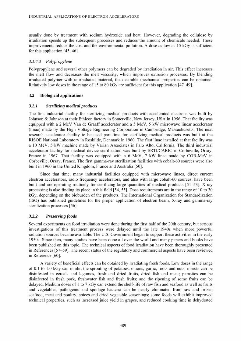
Fig. 3: Electron energy deposition vs thickness x density in polyethylene at 1.0, 1.5, 2.0 and 3.0 MeV incident electron energy. The beam window thickness is 40 um of titanium. The air thickness between the window and the treated material is 15 cm at 0.0012 g/cu cm. From Refs. [74, 75].
0.0
0.5
1.0
1.5
2.0
2.5
3.0
0.0 1.0 2.0 3.0 4.0 5.0 6.0
Thickness x Density ( sq cm / g )
Elec
tron
Ener
gy D
epos
ition
( MeV
sq c
m /
g )
5.0 MeV7.5 MeV10 MeV
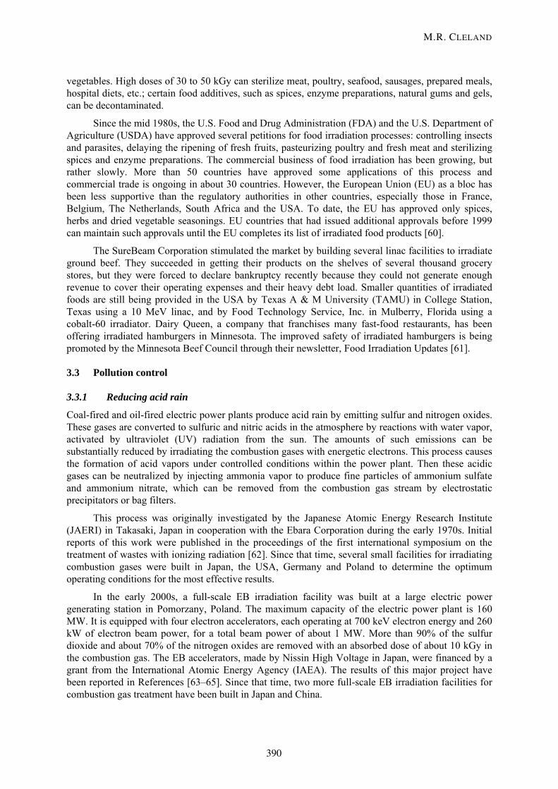
Fig. 4: Electron energy deposition vs thickness x density in polyethylene at 5.0, 7.5 and 10 MeV incident electron energy. The beam window thickness is 40 um of titanium. The air thickness between the window and the treated material is 15 cm at 0.0012 g/cu cm. From Refs. [74, 75].
The range parameters can be correlated with the incident electron energy E with sufficient accuracy for industrial applications by using the following linear equations:
R(opt) = 0.404 E – 0.161 (6)
R(50) = 0.435 E – 0.152 (7)
R(50e) = 0.458 E – 0.152 (8)
R(p) = 0.510 E – 0.145 (9)
where the electron range values are in g/cm2 and the electron energy values are in MeV.
INDUSTRIAL APPLICATIONS OF ELECTRON ACCELERATORS
393
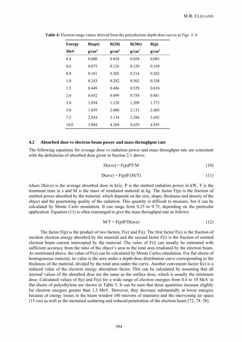
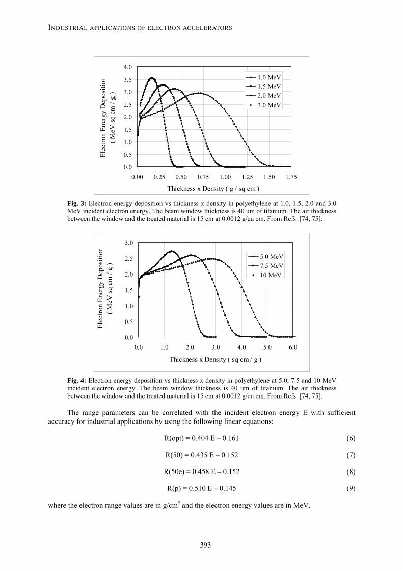
Table 4: Electron range values derived from the polyethylene depth-dose curves in Figs. 2–4
Energy R(opt) R(50) R(50e) R(p)
MeV g/cm2 g/cm2 g/cm2 g/cm2
0.4 0.000 0.054 0.054 0.083
0.6 0.075 0.126 0.129 0.169
0.8 0.161 0.202 0.214 0.262
1.0 0.243 0.282 0.302 0.358
1.5 0.449 0.486 0.529 0.610
2.0 0.652 0.699 0.754 0.861
3.0 1.054 1.128 1.209 1.373
5.0 1.859 2.000 2.131 2.405
7.5 2.854 3.134 3.284 3.682
10.0 3.884 4.204 4.429 4.955
4.2 Absorbed dose vs electron beam power and mass throughput rate
The following equations for average dose vs radiation power and mass throughput rate are consistent with the definitions of absorbed dose given in Section 2.1 above:
D(ave) = F(p)PT/M (10)
D(ave) = F(p)P/(M/T) (11)
where D(ave) is the average absorbed dose in kGy, P is the emitted radiation power in kW, T is the treatment time in s and M is the mass of irradiated material in kg. The factor F(p) is the fraction of emitted power absorbed by the material, which depends on the size, shape, thickness and density of the object and the penetrating quality of the radiation. This quantity is difficult to measure, but it can be calculated by Monte Carlo simulation. It can range from 0.25 to 0.75, depending on the particular application. Equation (11) is often rearranged to give the mass throughput rate as follows:
M/T = F(p)P/D(ave) (12)
The factor F(p) is the product of two factors, F(e) and F(i). The first factor F(e) is the fraction of incident electron energy absorbed by the material and the second factor F(i) is the fraction of emitted electron beam current intercepted by the material. The value of F(i) can usually be estimated with sufficient accuracy from the ratio of the object’s area to the total area irradiated by the electron beam. As mentioned above, the value of F(e) can be calculated by Monte Carlos simulation. For flat sheets of homogeneous material, its value is the area under a depth-dose distribution curve corresponding to the thickness of the material, divided by the total area under the curve. Another convenient factor f(e) is a reduced value of the electron energy absorption factor. This can be calculated by assuming that all internal values of the absorbed dose are the same as the surface dose, which is usually the minimum dose. Calculated values of f(e) and F(e) for a wide range of electron energies from 0.4 to 10 MeV in flat sheets of polyethylene are shown in Table 5. It can be seen that these quantities increase slightly for electron energies greater than 1.5 MeV. However, they decrease substantially at lower energies because of energy losses in the beam window (40 microns of titanium) and the intervening air space (15 cm) as well as the increased scattering and reduced penetration of the electron beam [72, 74–76].
M.R. CLELAND
394
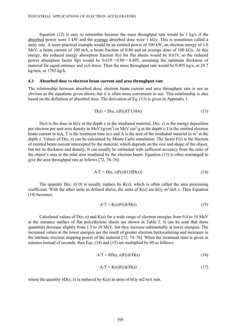
Equation (12) is easy to remember because the mass throughput rate would be 1 kg/s if the absorbed power were 1 kW and the average absorbed dose were 1 kGy. This is sometimes called a unity rule. A more practical example would be an emitted power of 100 kW, an electron energy of 1.0 MeV, a beam current of 100 mA, a beam fraction of 0.80 and an average dose of 100 kGy. At this energy, the reduced energy absorption fraction f(e) for flat sheets would be 0.619, so the reduced power absorption factor f(p) would be 0.619 × 0.80 = 0.495, assuming the optimum thickness of material for equal entrance and exit doses. Then the mass throughput rate would be 0.495 kg/s, or 29.7 kg/min, or 1782 kg/h.
4.3 Absorbed dose vs electron beam current and area throughput rate
The relationship between absorbed dose, electron beam current and area throughput rate is not as obvious as the equations given above, but it is often more convenient to use. This relationship is also based on the definition of absorbed dose. The derivation of Eq. (13) is given in Appendix 1.
D(z) = D(e, z)F(i)IT/(10A) (13)
D(z) is the dose in kGy at the depth z in the irradiated material, D(e, z) is the energy deposition per electron per unit area density in MeV/(g/cm2) or MeV cm2/g at the depth z, I is the emitted electron beam current in mA, T is the treatment time in s and A is the area of the irradiated material in m2 at the depth z. Values of D(e, z) can be calculated by Monte Carlo simulation. The factor F(i) is the fraction of emitted beam current intercepted by the material, which depends on the size and shape of the object, but not its thickness and density. It can usually be estimated with sufficient accuracy from the ratio of the object’s area to the total area irradiated by the electron beam. Equation (13) is often rearranged to give the area throughput rate as follows [72, 74–76]:
A/T = D(e, z)F(i)I/(10D(z)) (14)
The quantity D(e, z)/10 is usually replace by K(z), which is often called the area processing coefficient. With the other units as defined above, the units of K(z) are kGy m2/mA s. Then Equation (14) becomes:
A/T = K(z)F(i)I/D(z) (15)
Calculated values of D(e, o) and K(o) for a wide range of electron energies from 0.4 to 10 MeV at the entrance surface of flat polyethylene sheets are shown in Table 5. It can be seen that these quantities decrease slightly from 1.5 to 10 MeV, but they increase substantially at lower energies. The increased values at the lower energies are the result of greater electron backscattering and increases in the intrinsic electron stopping power of the material [72, 74–76]. When the treatment time is given in minutes instead of seconds, then Eqs. (14) and (15) are multiplied by 60 as follows:
A/T = 6D(e, z)F(i)I/D(z) (16)
A/T = K(z)F(i)I/D(z) (17)
where the quantity 6D(e, z) is replaced by K(z) in units of kGy m2/mA min.
INDUSTRIAL APPLICATIONS OF ELECTRON ACCELERATORS
395
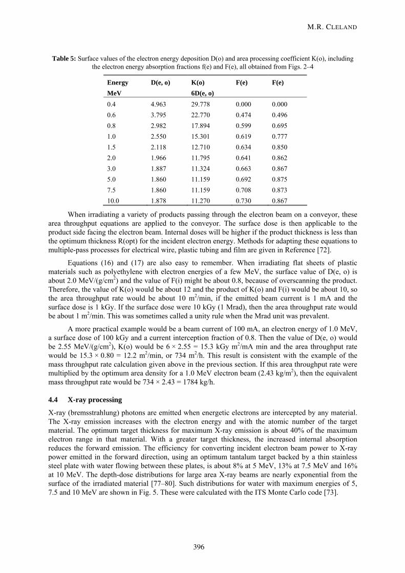
Table 5: Surface values of the electron energy deposition D(o) and area processing coefficient K(o), including the electron energy absorption fractions f(e) and F(e), all obtained from Figs. 2–4
Energy D(e, o) K(o) F(e) F(e) MeV 6D(e, o) 0.4 4.963 29.778 0.000 0.000 0.6 3.795 22.770 0.474 0.496 0.8 2.982 17.894 0.599 0.695 1.0 2.550 15.301 0.619 0.777 1.5 2.118 12.710 0.634 0.850 2.0 1.966 11.795 0.641 0.862 3.0 1.887 11.324 0.663 0.867 5.0 1.860 11.159 0.692 0.875 7.5 1.860 11.159 0.708 0.873 10.0 1.878 11.270 0.730 0.867
When irradiating a variety of products passing through the electron beam on a conveyor, these area throughput equations are applied to the conveyor. The surface dose is then applicable to the product side facing the electron beam. Internal doses will be higher if the product thickness is less than the optimum thickness R(opt) for the incident electron energy. Methods for adapting these equations to multiple-pass processes for electrical wire, plastic tubing and film are given in Reference [72].
Equations (16) and (17) are also easy to remember. When irradiating flat sheets of plastic materials such as polyethylene with electron energies of a few MeV, the surface value of D(e, o) is about 2.0 MeV/(g/cm2) and the value of F(i) might be about 0.8, because of overscanning the product. Therefore, the value of K(o) would be about 12 and the product of K(o) and F(i) would be about 10, so the area throughput rate would be about 10 m2/min, if the emitted beam current is 1 mA and the surface dose is 1 kGy. If the surface dose were 10 kGy (1 Mrad), then the area throughput rate would be about 1 m2/min. This was sometimes called a unity rule when the Mrad unit was prevalent.
A more practical example would be a beam current of 100 mA, an electron energy of 1.0 MeV, a surface dose of 100 kGy and a current interception fraction of 0.8. Then the value of D(e, o) would be 2.55 MeV/(g/cm2), K(o) would be 6 × 2.55 = 15.3 kGy m2/mA min and the area throughput rate would be 15.3 × 0.80 = 12.2 m2/min, or 734 m2/h. This result is consistent with the example of the mass throughput rate calculation given above in the previous section. If this area throughput rate were multiplied by the optimum area density for a 1.0 MeV electron beam (2.43 kg/m2), then the equivalent mass throughput rate would be 734 × 2.43 = 1784 kg/h.
4.4 X-ray processing
X-ray (bremsstrahlung) photons are emitted when energetic electrons are intercepted by any material. The X-ray emission increases with the electron energy and with the atomic number of the target material. The optimum target thickness for maximum X-ray emission is about 40% of the maximum electron range in that material. With a greater target thickness, the increased internal absorption reduces the forward emission. The efficiency for converting incident electron beam power to X-ray power emitted in the forward direction, using an optimum tantalum target backed by a thin stainless steel plate with water flowing between these plates, is about 8% at 5 MeV, 13% at 7.5 MeV and 16% at 10 MeV. The depth-dose distributions for large area X-ray beams are nearly exponential from the surface of the irradiated material [77–80]. Such distributions for water with maximum energies of 5, 7.5 and 10 MeV are shown in Fig. 5. These were calculated with the ITS Monte Carlo code [73].
M.R. CLELAND
396

0 10 20 30 40Depth (cm)
Dos
e (rel. u
nits)
10 MeV7.5 MeV5 MeV
Fig. 5: Broad beam X-ray (bremsstrahlung) absorbed dose vs depth in water with maximum energies of 10, 7.5 and 5 MeV. From Reference [80].
To obtain maximum X-ray power utilization when materials with low atomic numbers are treated from opposite sides, the optimum thickness should be about 34 g/cm2 at 5 MeV, 38 g/cm2 at 7.5 MeV and 43 g/cm2 at 10 MeV. The practical value of X-ray power utilization efficiency is defined by the minimum dose in the middle of the material multiplied by the total mass throughput rate and divided by the emitted X-ray power. Increasing the thickness beyond the optimum value reduces the minimum dose more than the mass throughput rate increases, thereby decreasing the practical power utilization efficiency [78–80]. Curves presenting the X-ray utilization efficiency and the dose uniformity ratio (DUR) vs material thickness for treatment from opposite sides with 5, 7.5 and 10 MeV are shown in Fig. 6.
0 10 20 30 40 50 60 70Treated Thickness (g/cm²)
1
1.5
2
2.5
3
3.5
4
Dm
ax/D
min
Phot
on P
ower
Utilizat
ion
(rel
. uni
ts)
10 MeV7.5 MeV5 MeV
Fig. 6: Broad beam X-ray (bremsstrahlung) power utilization and dose uniformity ratio vs thicknesss in water for treatment from opposite sides with maximum energies of 10, 7.5 and 5 MeV. From Refs. [79, 80].
INDUSTRIAL APPLICATIONS OF ELECTRON ACCELERATORS
397
With X-ray energies above 1 MeV, the maximum intensity is in the same direction as the electron beam, and the angular distribution becomes narrower as the electron energy increases. These properties enhance the power utilization in comparison to gamma rays from radioactive nuclides, which are emitted isotropically. With X-ray energies above 5 MeV, the penetration is greater and the DUR is lower than with gamma rays from cobalt-60 [78].
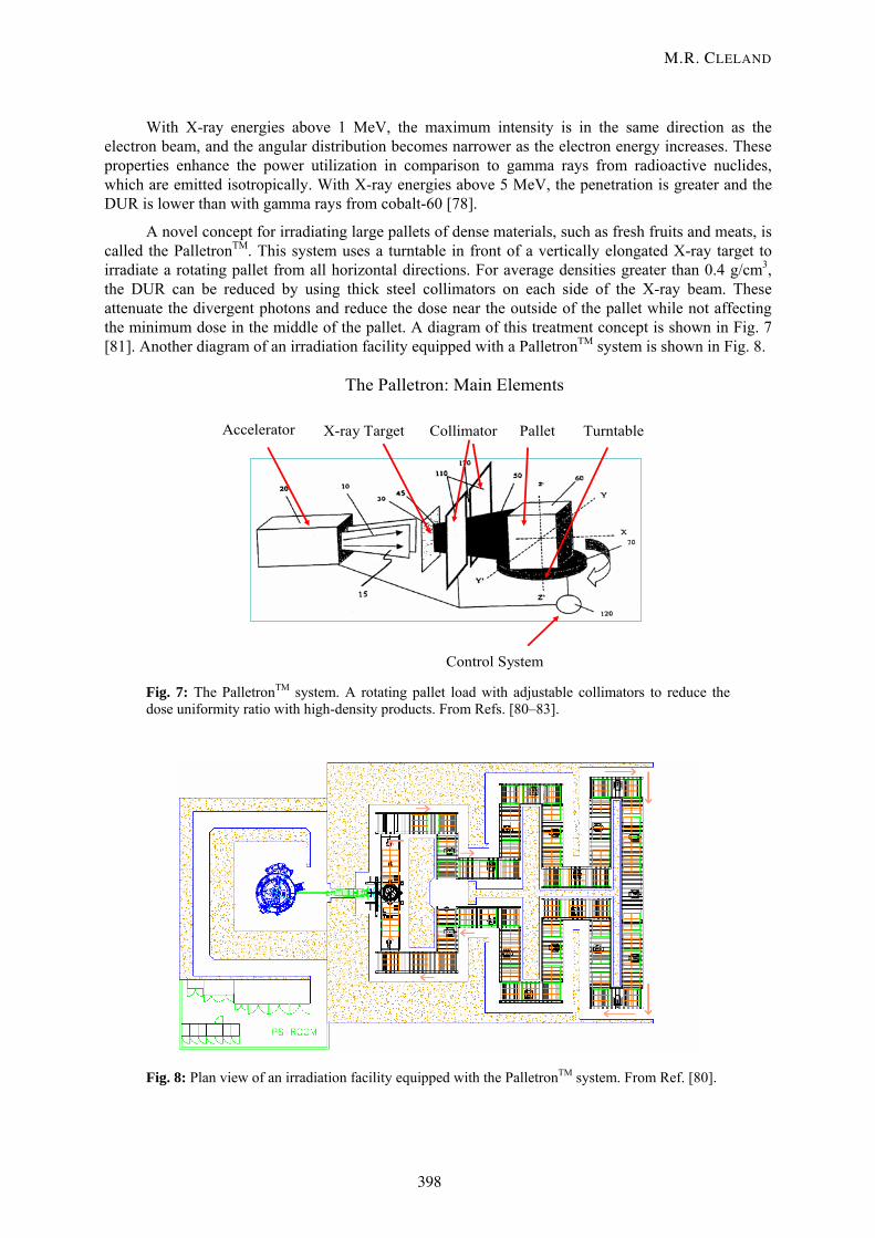
A novel concept for irradiating large pallets of dense materials, such as fresh fruits and meats, is called the PalletronTM. This system uses a turntable in front of a vertically elongated X-ray target to irradiate a rotating pallet from all horizontal directions. For average densities greater than 0.4 g/cm3, the DUR can be reduced by using thick steel collimators on each side of the X-ray beam. These attenuate the divergent photons and reduce the dose near the outside of the pallet while not affecting the minimum dose in the middle of the pallet. A diagram of this treatment concept is shown in Fig. 7 [81]. Another diagram of an irradiation facility equipped with a PalletronTM system is shown in Fig. 8.
The Palletron: Main Elements
Accelerator X-ray Target Collimator Pallet Turntable
Control System
Fig. 7: The PalletronTM system. A rotating pallet load with adjustable collimators to reduce the dose uniformity ratio with high-density products. From Refs. [80–83].
Fig. 8: Plan view of an irradiation facility equipped with the PalletronTM system. From Ref. [80].
M.R. CLELAND
398
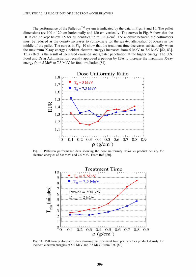
The performance of the PalletronTM system is indicated by the data in Figs. 9 and 10. The pallet dimensions are 100 × 120 cm horizontally and 180 cm vertically. The curves in Fig. 9 show that the DUR can be kept below 1.5 for all densities up to 0.8 g/cm3. The aperture between the collimators must be reduced as the density increases to compensate for the greater attenuation of X-rays in the middle of the pallet. The curves in Fig. 10 show that the treatment time decreases substantially when the maximum X-ray energy (incident electron energy) increases from 5 MeV to 7.5 MeV [82, 83]. This effect is the result of increased emission and greater penetration at the higher energy. The U.S. Food and Drug Administration recently approved a petition by IBA to increase the maximum X-ray energy from 5 MeV to 7.5 MeV for food irradiation [84].
Fig. 9: Palletron performance data showing the dose uniformity ratios vs product density for electron energies of 5.0 MeV and 7.5 MeV. From Ref. [80].
Fig. 10: Palletron performance data showing the treatment time per pallet vs product density for incident electron energies of 5.0 MeV and 7.5 MeV. From Ref. [80].
INDUSTRIAL APPLICATIONS OF ELECTRON ACCELERATORS
399

5 Industrial electron accelerators Detailed information about the design concepts and operational characteristics of various particle accelerators can be found in books and conference proceedings [85–93]. More than 1000 electron accelerators are now being used for industrial radiation processing. Several basic types, such as high voltage direct current, microwave and radio frequency systems are employed in this field. The most appropriate type for a particular industrial application depends on the electron energy and beam power requirements of the process [90].
5.1 High voltage DC accelerators
5.1.1 Electron acceleration tubes
Single-gap acceleration tubes are used in the low voltage range from 75 kV to 300 kV. The cathode, a directly heated filament, is connected to the negative terminal of a high voltage generator. The anode, a thin metallic foil at ground potential, permits the electrons to emerge from the evacuated region to irradiate products in air. The cathode extends in a direction parallel to an elongated anode or beam window to produce a wide electron beam without scanning. Single cathodes with lengths ranging from 25 cm to more than 100 cm are commonly used [94, 95]. A diagram of this type of acceleration tube is shown in Fig 11. Accelerators of this type have been supplied by Energy Sciences Inc. and by Advanced Electron Beams in the United States. ESI is now a subsidiary of Iwasaki Electric Company in Japan. Multiple cathodes with lengths of about 15 to 20 cm are used in a parallel array to produce an electron beam extended in two dimensions [96]. A diagram of this type of acceleration tube is shown is Fig. 12. Accelerators of this type were developed and supplied by RPC Industries and are now offered by PCT Engineered Systems in the United States.
Fig. 11: Diagram of a single-gap electron acceleration tube with one elongated filament. From Ref. [94].
Fig.12: Diagram of a single-gap electron acceleration tube with multiple parallel filaments. From Ref. [96].
With voltages higher than 300 kV, multiple-gap acceleration tubes must be used to prevent internal electrical discharges. Such tubes consist of a series of metallic discs (sometimes called diaphragms or dynodes) with central apertures for the electron beam. These discs are bonded to glass or ceramic rings to make a vacuum tight assembly. The discs are connected to a string of resistors which provide intermediate voltages between the cathode and the grounded anode. This produces a uniform axial electric field inside the tube for accelerating the electrons [97–100]. Relatively low field gradients of 12 to 15 kV/cm are typical in industrial accelerators. For accelerating beam currents of more than a few milliamperes, the discs have cupped internal sections or overlapping convolutions to prevent scattered high energy particles from striking the insulating rings [101, 102]. Such effects could degrade the insulators and generate non-uniform radial electric fields, which would make the beam unstable. Fig. 13 shows a diagram of a multiple-gap tube with cupped discs.
M.R. CLELAND
400
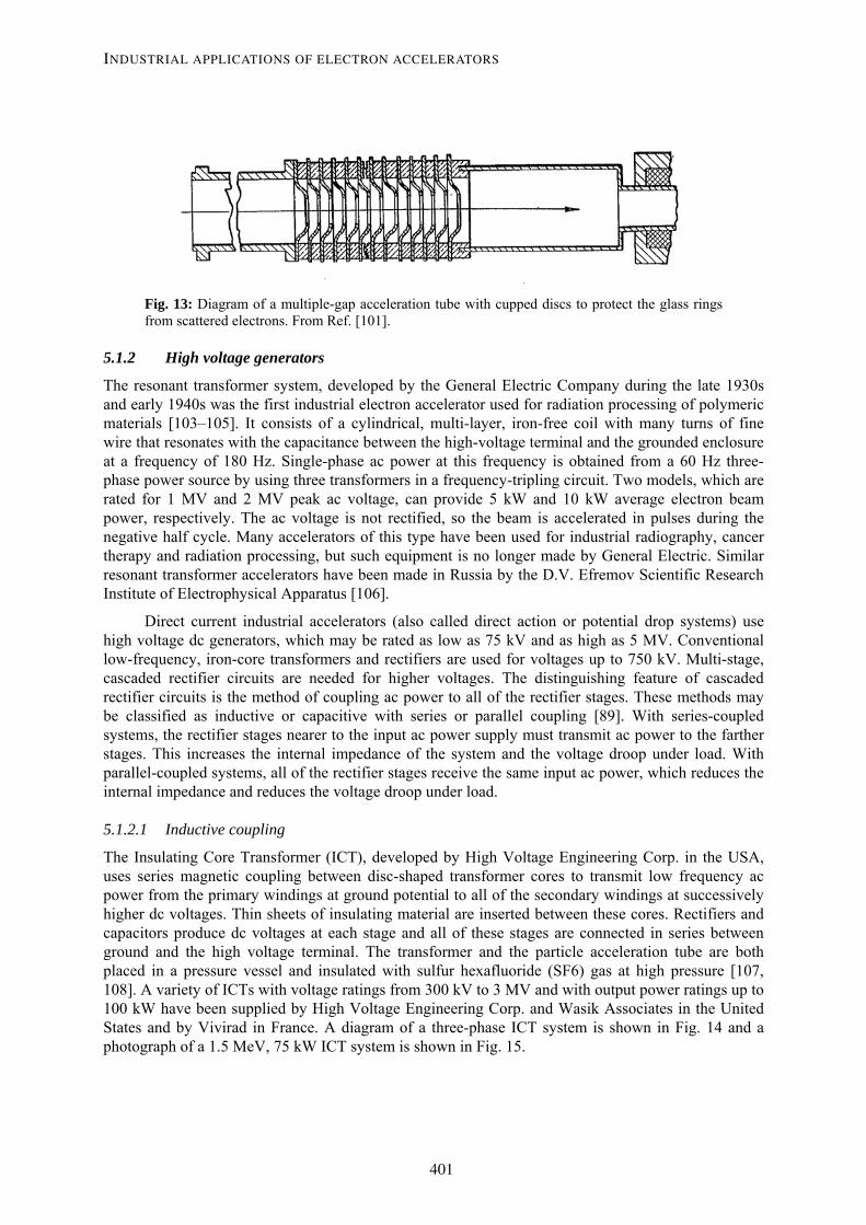
Fig. 13: Diagram of a multiple-gap acceleration tube with cupped discs to protect the glass rings from scattered electrons. From Ref. [101].
5.1.2 High voltage generators
The resonant transformer system, developed by the General Electric Company during the late 1930s and early 1940s was the first industrial electron accelerator used for radiation processing of polymeric materials [103–105]. It consists of a cylindrical, multi-layer, iron-free coil with many turns of fine wire that resonates with the capacitance between the high-voltage terminal and the grounded enclosure at a frequency of 180 Hz. Single-phase ac power at this frequency is obtained from a 60 Hz three-phase power source by using three transformers in a frequency-tripling circuit. Two models, which are rated for 1 MV and 2 MV peak ac voltage, can provide 5 kW and 10 kW average electron beam power, respectively. The ac voltage is not rectified, so the beam is accelerated in pulses during the negative half cycle. Many accelerators of this type have been used for industrial radiography, cancer therapy and radiation processing, but such equipment is no longer made by General Electric. Similar resonant transformer accelerators have been made in Russia by the D.V. Efremov Scientific Research Institute of Electrophysical Apparatus [106].
Direct current industrial accelerators (also called direct action or potential drop systems) use high voltage dc generators, which may be rated as low as 75 kV and as high as 5 MV. Conventional low-frequency, iron-core transformers and rectifiers are used for voltages up to 750 kV. Multi-stage, cascaded rectifier circuits are needed for higher voltages. The distinguishing feature of cascaded rectifier circuits is the method of coupling ac power to all of the rectifier stages. These methods may be classified as inductive or capacitive with series or parallel coupling [89]. With series-coupled systems, the rectifier stages nearer to the input ac power supply must transmit ac power to the farther stages. This increases the internal impedance of the system and the voltage droop under load. With parallel-coupled systems, all of the rectifier stages receive the same input ac power, which reduces the internal impedance and reduces the voltage droop under load.
5.1.2.1 Inductive coupling
The Insulating Core Transformer (ICT), developed by High Voltage Engineering Corp. in the USA, uses series magnetic coupling between disc-shaped transformer cores to transmit low frequency ac power from the primary windings at ground potential to all of the secondary windings at successively higher dc voltages. Thin sheets of insulating material are inserted between these cores. Rectifiers and capacitors produce dc voltages at each stage and all of these stages are connected in series between ground and the high voltage terminal. The transformer and the particle acceleration tube are both placed in a pressure vessel and insulated with sulfur hexafluoride (SF6) gas at high pressure [107, 108]. A variety of ICTs with voltage ratings from 300 kV to 3 MV and with output power ratings up to 100 kW have been supplied by High Voltage Engineering Corp. and Wasik Associates in the United States and by Vivirad in France. A diagram of a three-phase ICT system is shown in Fig. 14 and a photograph of a 1.5 MeV, 75 kW ICT system is shown in Fig. 15.
INDUSTRIAL APPLICATIONS OF ELECTRON ACCELERATORS
401
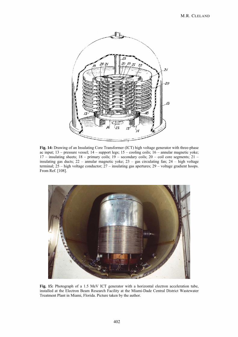
Fig. 14: Drawing of an Insulating Core Transformer (ICT) high voltage generator with three-phase ac input; 13 – pressure vessel; 14 – support legs; 15 – cooling coils; 16 – annular magnetic yoke; 17 – insulating sheets; 18 – primary coils; 19 – secondary coils; 20 – coil core segments; 21 – insulating gas ducts; 22 – annular magnetic yoke; 23 – gas circulating fan; 24 – high voltage terminal; 25 – high voltage conductor; 27 – insulating gas apertures; 29 – voltage gradient hoops. From Ref. [108].
Fig. 15: Photograph of a 1.5 MeV ICT generator with a horizontal electron acceleration tube, installed at the Electron Beam Research Facility at the Miami-Dade Central District Wastewater Treatment Plant in Miami, Florida. Picture taken by the author.
M.R. CLELAND
402

The ELV multi-stage, transformer-rectifier system developed by the Budker Institute of Nuclear Physics in Russia uses parallel magnetic coupling to transmit single-phase, low-frequency ac power from a conical primary winding to many circular high-voltage secondary windings. The primary winding extends to the full length of the high-voltage assembly, as shown in Fig. 16. Rectifiers and filter capacitors are connected to each secondary winding. A variety of gas-insulated ELV’s have been made with voltage ratings as low as 400 kV and as high as 2.5 MV with output power ratings up to 400 kW at 1 MV and 90 kW at 2.5 MV [109].
Fig. 16: Diagram of an ELV accelerator; 1 – primary winding; 2 – secondary winding; 3 – magnetic circuit; 7 – voltage doubler circuit; 8 – high voltage electrode; 9 – accelerating tube; 10 – pressure vessel. From Ref. [89].
5.1.2.2 Capacitive coupling
Cockcroft-Walton accelerators transmit ac power to multiple rectifier stages through two columns of high-voltage capacitors, which are connected in series. Multi-stage, series-coupled cascade circuits were first proposed by H. Greinacher [110]. Many large, air-insulated, high voltage generators and particle accelerators of this type with voltages up to at least 1.5 MV were made during the 1930s and 1940s by N.V. Philips Gloeilampenfabrieken in The Netherlands [111]. During the 1950s, Emil Haefely & Co. Ltd. in Switzerland developed symmetrical, series cascade generators with three columns of capacitors. Their circuit diagram is shown in Fig. 17. The balanced ac input voltage and the central column of capacitors significantly reduce the ac ripple voltage at the high-voltage terminal. They have made ion accelerators with voltage ratings up to 4 MV with compressed gas insulation [112–115].
Nissin High Voltage Co. Ltd. in Japan also makes balanced, series cascade systems, which are similar to the Haefely symmetrical cascades but without the central capacitors. Low ac ripple voltage is not a requirement for industrial applications, so these large, expensive components are not needed. The NHV systems are energized with medium-frequency ac power at about 3 kHz to allow a reduction in the total capacitance of the system. Electron accelerators of this type have been produced with voltages as high as 5 MV and electron beam powers up to 150 kW using compressed gas insulation [116, 117].
INDUSTRIAL APPLICATIONS OF ELECTRON ACCELERATORS
403

Fig. 17: Circuit diagram of a symmetrical, series-coupled, capacitive cascade generator. From Ref. [115].
Multi-stage, parallel-coupled cascade rectifier circuits were first proposed by Schenkel [118] and later by Schade [119]. However, the requirement for coupling capacitors to withstand successively higher voltages was perceived to be a disadvantage in comparison to the series-coupled Greinacher cascade circuit. The lower impedance of the Schenkel circuit was not important for low-current applications. The challenge of making a compact, high-current, parallel-coupled system was met by Radiation Dynamics, Inc., which developed the Dynamitron accelerator during the 1950s and 1960s.
Dynamitrons transmit high-frequency (about 100 kHz) ac power to all of the rectifier stages in parallel by means of semi-cylindrical electrodes which surround the high voltage column. These electrodes are connected to a center-grounded, iron-free, high-Q transformer. This combination forms a balanced resonant circuit, which is energized with a triode oscillator circuit. The semi-cylindrical electrodes induce ac voltages between pairs of semi-circular corona rings, which are connected to the rectifier junctions. All of the rectifier stages are connected in series between ground and the high voltage terminal. Electron accelerators of this type have been produced with voltage ratings as low as 0.4 MV and as high as 5 MV with electron beam powers up to 250 kW using compressed SF6 gas insulation [102, 120-122]. Diagrams of the Dynamitron system are shown in Figs. 18 and 19 and a photograph of a 5 MV unit is shown in Fig. 20.
M.R. CLELAND
404
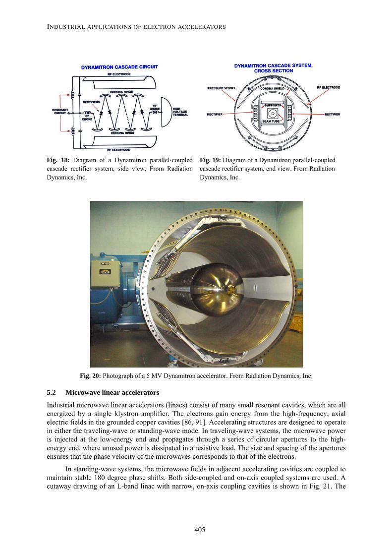
Fig. 18: Diagram of a Dynamitron parallel-coupled cascade rectifier system, side view. From Radiation Dynamics, Inc.
Fig. 19: Diagram of a Dynamitron parallel-coupled cascade rectifier system, end view. From Radiation Dynamics, Inc.
Fig. 20: Photograph of a 5 MV Dynamitron accelerator. From Radiation Dynamics, Inc.
5.2 Microwave linear accelerators
Industrial microwave linear accelerators (linacs) consist of many small resonant cavities, which are all energized by a single klystron amplifier. The electrons gain energy from the high-frequency, axial electric fields in the grounded copper cavities [86, 91]. Accelerating structures are designed to operate in either the traveling-wave or standing-wave mode. In traveling-wave systems, the microwave power is injected at the low-energy end and propagates through a series of circular apertures to the high-energy end, where unused power is dissipated in a resistive load. The size and spacing of the apertures ensures that the phase velocity of the microwaves corresponds to that of the electrons.
In standing-wave systems, the microwave fields in adjacent accelerating cavities are coupled to maintain stable 180 degree phase shifts. Both side-coupled and on-axis coupled systems are used. A cutaway drawing of an L-band linac with narrow, on-axis coupling cavities is shown in Fig. 21. The
INDUSTRIAL APPLICATIONS OF ELECTRON ACCELERATORS
405

cavity spacing is determined by the resonant frequency and the electron transit times. These high-Q cavities must have accurate dimensions so that they all resonate at the same frequency, and must have stable temperatures to keep this frequency matched to that of the klystron. In order to obtain typical energy gains of several MeV per meter, the peak microwave power must be several megawatts. So linacs must be pulsed with a low duty factor to reduce the average power loss to an acceptable level.
Fig. 21: Three-dimensional cutaway view of an L-band linac with on-axis coupling cavities. From Ref. [129].
Linacs for radiation processing may be designed to resonate at the S-band frequency (near 3,000 MHz) or the L-band frequency (near 1,300 MHz). S-band systems, which are more often applied in this field, provide electron energies up to 10 MeV and average beam powers up to 25 kW [123–125]. Such systems have been supplied by Linac Technologies in France, Mevex Corporation in Canada, Titan PSD in the United States and Mitsubishi Heavy Industries in Japan. Larger L-band systems provide similar energies and higher average beam powers [126–129]. A 10 MeV, 60 kW system, which was developed by Atomic Energy of Canada, is now offered by Iotron Industries in Canada and a 5 MeV, 100 kW system has been developed by Titan PSD in the United States.
5.3 Radio frequency accelerators
Electron energies from 0.4 MeV to 5 MeV with average beam powers up to 50 kW can be produced with radio frequency accelerators using a single, large resonant cavity. The energy is gained in one pass along the axis of the toroidal cavity. ILU accelerators of this type have been produced by the Budker Institute of Nuclear Physics in Russia. The resonant frequencies are in the range of 110 to 176 MHz and the rf power is supplied with triode tubes. The rf system is self-tuning, so accurate cavity dimensions and temperature controls to stabilize the resonant frequency are not needed [130–132]. A diagram of an ILU-6 accelerator is shown in Fig. 22.
Higher electron energies can be obtained with a single, large resonant cavity by accelerating the electrons repeatedly with the same cavity. This type of system, called a Rhodotron, was invented at the Commissariat a l’Energy Atomique laboratory in France and developed for industrial applications by Ion Beam Applications in Belgium [133–137]. It employs a coaxial cavity in contrast to the toroidal cavity used in the ILU system. After each pass, the beam is deflected by an external magnet and returns to the cavity. A diagram of the beam trajectories is shown in Fig. 23. A photograph of an IBA Rhodotron being assembled is shown in Fig. 24. The large cavity is about 2 meters in diameter and resonates at 107.5 MHz. It is energized with a tetrode tube in a self-tuning rf system, so accurate cavity dimensions and temperature controls to stabilize the resonant frequency are not needed.
M.R. CLELAND
406
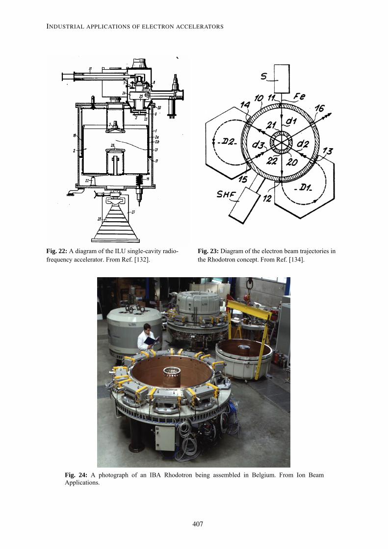
Fig. 22: A diagram of the ILU single-cavity radio-frequency accelerator. From Ref. [132].
Fig. 23: Diagram of the electron beam trajectories in the Rhodotron concept. From Ref. [134].
Fig. 24: A photograph of an IBA Rhodotron being assembled in Belgium. From Ion Beam Applications.
INDUSTRIAL APPLICATIONS OF ELECTRON ACCELERATORS
407
Model TT200 uses 10 passes and is rated for 10 MeV and 80 kW of average beam power. Model TT300 also uses 10 passes and is rated for 10 MeV and 200 kW. Model TT1000 uses 6 passes and is rated for 7 MeV and 700 kW. This very high beam power will be useful for X-ray applications. The smaller Model TT100 resonates at 215 MHz. It uses 12 passes and is rated for 10 MeV and 35 kW. By turning off one of the beam bending magnets, the beam can be extracted after fewer passes to obtain a lower energy.
Because of the low energy gain per pass, the large dimensions and the low resonant frequency in comparison to a microwave linac, the rf power loss in a Rhodotron cavity is less than 100 kW. This allows operation in the continuous-wave (cw) mode. In contrast to pulsed beams, a cw electron beam can be scanned at any rate that might be required by the product handling system.
6 Conclusion Ionizing radiations in the form of energetic electrons and X-rays (bremsstrahlung) are being used for many practical applications. High-energy, high-power beams can modify the physical, chemical and biological properties of materials and commercial products on an industrial scale. The engineering aspects of these processes are well understood, so the objectives can be achieved reliably. Many electron accelerators with a variety of specifications have been built and installed for these purposes. These technologies have been evolving for more than fifty years, and this field is still expanding.
References [1] W.L. McLaughlin, et al. Dosimetry for Radiation Processing, Taylor & Francis, New York
(1989). [2] A. Charlesby, Atomic Radiations and Polymers, Pergamon Press, London (1960). [3] A. Charlesby, Use of High Energy Radiation for Crosslinking and Degradation, Radiat. Phys.
Chem. Vol. 9, Nos. 1-3 (1977) 17-29. [4] A. Chapiro, Radiation Chemistry of Polymeric Systems, Interscience Publishers, John Wiley &
Sons, New York (1962). [5] J. Silverman, Basic Concepts of Radiation Processing, Radiat. Phys. Chem. Vol. 9, Nos. 1-3
(1977) 1-15. [6] J. Silverman, Radiation Processing: The Industrial Applications of Radiation Chemistry, J.
Chem. Ed. Vol. 58, No. 2 (1981) 168-173. [7] M.R. Cleland, Radiation Processing: Basic Concepts and Practical Aspects, J. Ind. Rad. Tech.,
Vol. 1, No. 3 (1983) 191-218. [8] Proceedings of the thirteen International Meetings on Radiation Processing, Rad. Phys. Chem.,
Pergamon, Elsevier Science, Inc., Tarrytown, New York, Vols. 9, 14, 18, 22, 25, 31, 35, 42, 46, 52, 57, 63, 71 (1977-2004).
[9] Proceedings of the five International Conferences on Ionizing Radiation and Polymers (IRaP), Nucl. Instr. Meth. Phys. Res., Section B, Beam Interactions with Materials and Atoms (NIMB), North-Holland, Elsevier Science, Amsterdam, Vol. 105 (1995), Vol. 131 (1997), Vol. 151 (1999), Vol. 185 (2001) and Vol. 208 (2003).
[10] Proceedings of the two Pacifichem Symposia on Polymer Radiation Chemistry, Rad. Phys. Chem., Pergamon, Elsevier Science, Inc., Tarrytown, New York, Vol. 48, No. 5 (1996) and Vol. 61, No. 1 (2001).
[11] J.W.T. Spinks and R.J. Woods, An Introduction to Radiation Chemistry, John Wiley & Sons, Inc., New York (1964).
M.R. CLELAND
408
[12] M. Dole (ed.), The Radiation Chemistry of Macromolecules, Academic Press, New York, Vol. I (1972), Vol. II (1973).
[13] R. Bradley, Radiation Technology Handbook, Marcel Dekker, Inc., New York (1984). [14] J.H. Bly, Electron Beam Processing, International Information Associates, Yardley, PA (1988). [15] Y. Tabata, Y. Ito and S. Tagawa (eds.), Handbook of Radiation Chemistry, CRC Press, Boca
Raton, Florida (1991). [16] A. Singh and J. Silverman (eds.), Radiation Processing of Polymers, Hanser, Munich (1992). [17] R.J. Woods and A.K. Pikaev, Applied Radiation Chemistry: Radiation Processing, Wiley, New
York (1994). [18] R. Clough and S. Shalaby (eds.), Irradiation of Polymers: Fundamentals and Technological
Applications, ACS Books, Washington, D.C. (1996). [19] University of Notre Dame Web Site: Go to www.nd.edu, Search for Radiation Laboratory,
Select Radiation Chem. Data Center, Select Recent Papers in Radiation Chemistry and Photochemistry.
[20] A. Zyball, Radiation Processing of Polymers, in Emerging Applications of Radiation Processing for the 21st Century, Report from a Technical Meeting Held at the International Atomic Energy Agency (IAEA), Vienna, Austria (2003) 134-142.
[21] S.V. Nablo and E.P. Tripp, Low-Energy Electron Process Applications, Radiat. Phys. Chem. Vol. 9, Nos. 1-3 (1977) 325-352.
[22] W.A. Frutiger and S.V. Nablo, Performance Characteristics of High Power, Multiple Gun, Electrocurtains, Radiat. Phys. Chem. Vol. 22, Nos. 3-5 (1983) 431-440.
[23] C.B. Saunders, et al, Electron Curing of Fibre-Reinforced Composites: An Industrial Application for High-Energy Accelerators, Radiat. Phys. Chem. Vol. 46, Nos. 4-6 (1995) 991-994.
[24] A.J. Berejka and C. Eberle, Electron Beam Curing of Composites in North America, Radiat. Phys. Chem, Vol. 63, Nos. 3-6 (2002) 551-556.
[25] A.J. Berejka, et al, X-Ray Curing of Composite Materials, in Proceedings of the CAARI 2004 Conference, Nucl. Instr. Meth. Phys. Res., Section B, Beam Interactions with Materials and Atoms (NIMB), North-Holland, Elsevier Science, Amsterdam (2005).
[26] A. Chapiro, Radiation Induced Grafting, Radiat. Phys. Chem. Vol. 9, Nos. 1-3 (1977) 55-67. [27] J.L. Garnett, Grafting, Radiat. Phys. Chem. Vol. 14, Nos. 1-2 (1979) 79-99. [28] F. Hu, S. Cheng and P. Peng, Studies on Hydrophilic Functional Polymer Membranes Prepared
by Radiation Grafting of Acrylonitrile, in Proceedings of the 8th International Conference on Radiation Processing of Polymer Materials, Beijing (1992).
[29] A. Chapiro, A Worldwide View of Radiation Processing, Radiat. Phys. Chem. Vol. 22, Nos. 1-2 (1983) 7-10.
[30] A.S. Hoffman, Applications of Radiation Processing in Biomedical Engineering – A Review of the Preparation and Properties of Novel Biomaterials, Radiat. Phys. Chem, Vol. 9, Nos. 1-3 (1977) 207-219.
[31] K. Dawes and L.C. Glover, Effects of Electron Beam and γ-Irradiation on Polymeric Materials, Chapter 41 in Physical Properties of Polymers Handbook, James E. Mark (ed.), AIP Press, American Institute of Physics, Woodbury, New York (1996).
[32] L.D. Loan, Applications of Radiation Processing in the Wire and Cable Field, Radiat. Phys. Chem. Vol. 9, Nos. 1-3 (1977) 253-259.
[33] E.W. Bennett, Jr., Applications of Irradiation to Industrial Wires and Cables, Radiat. Phys. Chem. Vol. 14, Nos. 3-6 (1979) 947-951.
INDUSTRIAL APPLICATIONS OF ELECTRON ACCELERATORS
409

[34] P.G. Goavec, Plastic Materials and Acome’s Use of High Energy Electron Processing in France, Radiat. Phys. Chem. Vol. 14, Nos. 1-2 (1979) 61-67.
[35] S. Ota, Current Status of Irradiated Heat-Shrinkable Tubing in Japan, Radiat. Phys. Chem. Vol. 18, Nos. 1-2 (1981) 81-87.
[36] W.G. Baird, Jr., Applications in Plastic Sheet and Film, Radiat. Phys. Chem. Vol. 9, Nos. 1-3 (1977) 225-233.
[37] J.D. Hunt and G. Alliger, Rubber – Application of Radiation to Tire Manufacture, Radiat. Phys. Chem. Vol 14, Nos. 1-2 (1979) 39-53.
[38] D.A. Trageser, Crosslinked Polyethylene Foam Processes, Radiat. Phys. Chem. Vol. 9, Nos. 1-3 (1977) 261-270.
[39] N. Sagane and H. Harayama, Radiation Crosslinked Polyethylene Foam, Radiat. Phys. Chem. Vol. 18, Nos. 1-2 (1981) 99-108.
[40] Y. Ikada, et al, Preparation of Hydrogels by Radiation Technique, Radiat. Phys. Chem. Vol. 9, Nos. 4-6 (1977) 633-645.
[41] R.L. Derbyshire, Treatment of Sintered Poly-Tetrafluoroethylene with Irradiation and Heat to Produce a Grindable Material, U.S. Patent No. 4,220,511 (1980).
[42] W.B. Neuberg and R. Luniewski, Apparatus and Method for Radiation Processing of Materials, U.S. Patent No. 4,748,005 (1988).
[43] W.B. Neuberg and R. Luniewski, Apparatus and Method for Radiation Processing of Materials, U.S. Patent No. 4,777,192 (1988).
[44] N.W. Neuberg, G. Poszmik and M. Sui, Method of Providing Friable Polytetrafluoroethylene Products, U.S. Patent No. 5,891,573 (1999).
[45] T.M. Stepanik, et al, Electron-Processing Technology: A Promising Application for the Viscose Industry, Radiat. Phys. Chem. Vol. 52, Nos. 1-6 (1998) 505-509.
[46] M.R. Cleland, et al, A Rhodotron Electron Beam Facility for the Pre-Treatment of Cellulosic Pulp, AIP Conference Proceedings 475, American Institute of Physics, Woodbury, New York (1998) 953-956.
[47] D.E. Boynton, Method of Visbreaking Polypropylene, U.S. Patent No. 4,282,076 (1981). [48] S.D. Williams and H.J. Yoo, Radiation Visbroken Polypropylene and Fibers Made Therefrom,
U.S. Patent No. 5,804,304 (1998). [49] S.D. Williams, H.J. Yoo and M.R. Drickman, Radiation Visbroken Polypropylene and Fibers
Made Therefrom, U.S. Patent No. 5,820,981 (1998). [50] L.B. Sztanyik, Application of Ionizing Radiation to Sterilization, in Technical Developments
and Prospects of Sterilization by Ionizing Radiation, in Proceedings of the first Johnson & Johnson conference on radiation sterilization, E.R.L. Gaughran and A.J. Goudie (eds.), Multiscience Publication Ltd., Montréal, Québec, Canada (1974) 6-38.
[51] M.R. Cleland, M.T. O’Neill and C.C. Thompson, Sterilization with Accelerated Electrons, Chapter 9 in Sterilization Technology, A Practical Guide for Manufacturers and Users of Health Care Products, R.F. Morrissey and G.B. Phillips (eds.), Van Nostrand Reinhold, New York (1993) 218-253.
[52] C.M. Herring and M.C. Saylor, Sterilization with Radioisotopes, Chapter 8 in Sterilization Technology, A Practical Guide for Manufacturers and Users of Health Care Products, R.F. Morrissey and G.B. Phillips (eds.), Van Nostrand Reinhold, New York (1993) 196-217.
[53] B.P. Fairand, Radiation Sterilization for Health Care Products, X-Ray, Gamma, and Electron Beam, CRC Press, Boca Raton, Florida (2002).
[54] Y. Aikawa, A New Facility for X-Ray Irradiation and Its Application, Radiat. Phys. Chem. Vol. 57, Nos. 3-6 (2000) 609-612.
M.R. CLELAND
410

[55] T. Watanabe, Best Use of High-Voltage, High-Powered Electron Beams: A New Approach to Contract Irradiation Services, Radiat. Phys. Chem. Vol. 57, Nos. 3-6 (2000) 635-639.
[56] ISO 11137, Sterilization of Health Care Products – Radiation. Part 1, Requirements for the Development, Validation and Routine Control of a Sterilization Process for Medical Devices. Part 2, Establishing the Sterilization Dose. Part 3, Guidance on Dosimetric Aspects. International Organization for Standardization (ISO), 1, rue de Varembé, Case Postale 56, CH-1211, Geneva 20, Switzerland. Web address: www.iso.org. The revised version will be printed in 2006.
[57] E.S. Josephson and M.S. Peterson (eds.), Preservation of Food by Ionizing Radiation, CRC Press, Boca Raton, Florida, Vol. I (1982), Vol. II (1983), Vol. III (1983).
[58] W.M. Urbain, Food Irradiation, Academic Press, New York (1986). [59] J.F. Diehl, Safety of Irradiated Foods, Second Edition, Marcel Dekker, New York (1995). [60] P. Loaharanu, Irradiated Foods, Fifth Edition, American Council on Science and Health, 1995
Broadway, New York, NY 10023 (2003). Web address, http://www.acsh.org, Select Publications, Select Browse Publications, Select Irradiated Foods, May 1, 2003, Select View PDF Version, Select PDF Document.
[61] Food Irradiation Update, Newsletter published by the Minnesota Beef Council, 2950 Metro Drive, Suite 102, Minneapolis, MN 55425 (2005). Web address, http://www.mnbeef.org, Select Food Irradiation, Select Food Irradiation Updates, Select an Issue.
[62] Radiation for a Clean Environment, Proceedings of the International Symposium on the Use of High-Level Radiation in Waste Treatment – Status and Prospects, STI/PUB/402, International Atomic Energy Agency (IAEA), Vienna, Austria (1975).
[63] A.G. Chmielewski, et al, Industrial Applications of Electron Beam Flue Gas Treatment, Emerging Applications of Radiation Processing for the 21st Century, Report from a Technical Meeting Held at the International Atomic Energy Agency (IAEA), Vienna, Austria (2003) 172-180.
[64] A.G. Chmielewski, et al, Industrial Plant for Flue Gas Treatment with High Power Electron Accelerators, AIP Conference Proceedings, Vol. 680, American Institute of Physics, Melville, New York (2003) 873-876.
[65] A.G. Chmielewski, et al, Operational Experience of the Industrial Plant for Electron Beam Flue Gas Treatment, Radiat. Phys. Chem. Vol. 71. Issues 1-2 (2004) 441-444.
[66] J.G. Trump, E.M. Merrill and K.A. Wright, Disinfection of Sewage Waste Water and Sludge by Electron Treatment, Radiat. Phys. Chem. Vol. 24, No. 1 (1984) 55-66.
[67] M.R. Cleland, R.A. Fernald and S.R. Maloof, Electron Beam Process Design for the Treatment of Wastes and Economic Feasibility of the Process, Radiat. Phys. Chem. Vol. 24, No. 1 (1984) 179-190.
[68] W.J. Cooper, R.D. Curry and K.E. O’Shea (eds.), Environmental Applications of Ionizing Radiation, John Wiley & Sons, Inc., New York (1998).
[69] B. Han, Requirements of Electron Accelerator for Environmental Application, Recent Developments in Electron Accelerator Technology and Applications, IAEA-Internal Report, Consultants’ Meeting, Quebec, Canada (2002) 151-165.
[70] I.E. Makarov, A. Ponomarev and B. Han, Demonstration Plant for Electron-Beam Treatment of Taegu Dye Industry Complex Wastewater, Emerging Applications of Radiation Processing for the 21st Century, Report from a Technical Meeting Held at the International Atomic Energy Agency (IAEA), Vienna, Austria (2003) 157-171.
[71] Cleland, M.R. and Farrell, J.P., Methods for Calculating Energy and Current Requirements for Industrial Electron Beam Processing, in Proceedings of the Fourth Conference on the Scientific & Industrial Applications of Small Accelerators, Institute of Electrical and Electronic Engineers, 76CH 1175-9 NPS, pp. 133-141, 1976.
INDUSTRIAL APPLICATIONS OF ELECTRON ACCELERATORS
411

[72] R.C. Becker, et al, Accelerator Requirements for Electron Beam Processing, Radiat. Phys. Chem. Vol. 14, Nos. 3-6 (1979) 353-375.
[73] CCC-467/ITS Code Package, 1994. Integrated TIGER Series of coupled electron/photon Monte Carlo transport codes, ITS Version 3.0, Radiation Safety Information Computational Center (RSICC), Oak Ridge, TN 37831, USA.
[74] R.A. Galloway, M.R. Cleland and T.F. Lisanti, Technical Information Series TIS-01666, Monte Carlo Calculations of High-Energy Electron Depth-Dose Distributions in Polyethylene, Radiation Dynamics, Inc., Edgewood, NY 11717 (2006).
[75] M. Cleland, et al, The Use of Dose and Charge Distributions in Electron Beam Processing, Radiat. Phys. Chem. Vol. 63, Nos. 3-6 (2002) 729-733.
[76] ISO/ASTM 51649:2002(E), Standard Practice for Dosimetry in an Electron Beam Facility for Radiation Processing at Energies Between 300 keV and 25 MeV, Annual Book of ASTM Standards, Vol. 12.02, Nuclear (II), Solar, and Geothermal Energy, ASTM International, 100 Barr Harbor Drive, PO Box C700, West Conshohocken, PA 19428-2959 USA.
[77] S.M. Seltzer, J.P. Farrell and J. Silverman, Bremsstrahlung Beams from High-Power Electron Accelerators for Use in Radiation Processing, IEEE Transactions on Nuclear Science, Vol. NS-30, No. 2 (1983) 1629-1632.
[78] M.R. Cleland and G.M. Pageau, Comparisons of X-Ray and Gamma-Ray Sources for Industrial Irradiation Processes, Nucl. Instr. Meth. Phys. Res. B24/25 (1987) 967-972.
[79] J. Meissner, et al, X-Ray Treatment at 5 MeV and Above, Radiat. Phys. Chem. Vol. 57, Nos. 3-6 (2000) 647-651.
[80] M.R. Cleland, Application of High Power X-Ray Generators for Processing Bulk Materials, IAEA-TECDOC-1420, Advances in Radiation Chemistry of Polymers, A.G. Chmielewski (ed.),
[81] International Atomic Energy Agency, Vienna, Austria (2004) 111-123. [82] J. Kotler and J. Borsa, Product Irradiator for Optimizing Dose Uniformity in Products, U.S.
Patent No. 6,504,898 (2003). [83] F. Stichelbaut, et al, The PalletronTM: A High-Dose Uniformity Pallet Irradiator with X-Rays,
American Institute of Physics (AIP) Conference Proceedings, Vol. 680 (2003) 891-894. [84] F. Stichelbaut, et al, The PalletronTM: A High-Dose Uniformity Pallet Irradiator with X-Rays,
Radiat. Phys. Chem. Vol. 71, Issues 1-2 (2004) 291-295. [85] Code of Federal Regulations, Irradiation in the Production, Processing and Handling of Food,
Final Rule, Food and Drug Administration, Department of Health and Human Services, 21 CFR Part 179, Docket No. 2003F-0088 (2004) Fed Reg 69(246):76844-76847.
[86] J.D. Craggs and J.M. Meek, High Voltage Laboratory Technique, Butterworths Scientific Publications, London (1954).
[87] P.M. Lapostolle and A.L. Septier (eds.), Linear Accelerators, North Holland Publishers, Amsterdam (1970).
[88] S. Humphries, Jr., Principles of Charged Particle Acceleration, John Wiley & Sons, New York (1986).
[89] W. Scharf, Particle Accelerators and Their Uses, Part 1, Accelerator Design, Part 2, Applications of Accelerators, Harwood Academic Publishers, New York (1986).
[90] E.A. Abramyan, Industrial Electron Accelerators and Applications, Hemisphere Publishing Corporation, New York (1988).
[91] M.R. Cleland, High Power Electron Accelerators for Industrial Radiation Processing, Chapter 3 in Radiation Processing of Polymers, A. Singh and J. Silverman (eds.), Hanser, Munich (1992) 23-49.
M.R. CLELAND
412
[92] A.W. Chao and M. Tigner (eds.), Handbook of Accelerator Physics and Engineering, World Scientific Publishing, River Edge, NJ 07661, USA, 2nd Printing (2002), M.R. Cleland, Section 1.6.7, High Voltage Electrodynamic Accelerators, 20-22.
[93] M.R. Cleland and L.A. Parks, Medium and High Energy Electron Beam Radiation Processing Equipment for Commercial Applications, Proceedings of the International Conference on Ionizing Radiation and Polymers (IRaP), Nucl. Instr. Meth. Phys. Res., Section B, Beam Interactions with Materials and Atoms (NIMB), North-Holland, Elsevier Science, Amsterdam, Vol. 208 (2003) 74-89.
[94] Proceedings of the Eighteen International Conferences on the Application of Accelerators in Research and Industry, U.S. Department of Energy (DOE), Washington, D.C. (1968-1974), Institute of Electrical and Electronics Engineers (IEEE), New York (1976-1983), Nuclear Instruments and Methods in Physics Research, Section B (NIMB), North-Holland, Elsevier Science, Amsterdam (1985-1995), American Institute of Physics, AIP Conference Proceedings (1997-2003), Nuclear Instruments and Methods in Physics Research, Section B (NIMB) (2005).
[95] B.S. Quintal, Apparatus for and Method of Producing an Energetic Electron Curtain, U.S. Patent No. 3,702,412 (1972).
[96] T. Avnery, Electron Beam Accelerator, U.S. Patent No. 5,962,995 (1999). [97] S.R. Farrell, L.J. Demeter and P.G. Woods, Broad Beam Electron Gun, U.S. Patent No.
3,863,163 (1975). [98] R.R. Machlett and J.W. Skehan, Insulating Structure, U.S. Patent No. 2,376,439 (1945). [99] R.J. Van de Graaff, J.G. Trump and W.W. Buchner, Reports on Progress in Physics, Vol. XI,
The Physical Society, UK (1948) 1. [100] J.G. Trump and R.W. Cloud, Laminated Envelope Structure for Electron Discharge Devices,
U.S. Patent No. 2,460,201 (1949). [101] R.J. Van de Graaff and W.W. Buechner, Apparatus for Generating an Accurately Focused Beam
of Charged Particles and for Related Purposes, U.S. Patent No. 2,517,260 (1950). [102] J.G. Trump, Method and Apparatus for Sterilizing by Electron Bombardment, U.S. Patent No.
2,785,313 (1957). [103] M.R. Cleland and P. Farrell, Dynamitrons of the Future, IEEE Transactions on Nuclear Science,
Vol. NS-12, No. 3, pp. 227-234, 1965. [104] W.F. Westendorp, High Voltage Apparatus, U.S. Patent No. 2,144,518 (1939). [105] E.E. Charleton, et al, A New Million-Volt X-Ray Outfit, J. Appl. Phys., Vol. 10 (1939) 374-
385. [106] J.W. Ranftl, Irradiated Polyethylene – A Case Study in the Economics of Production Use of
Electron Beam Radiation, Proceedings of the Conference on Applications of Large Radiation Sources in Industry, Vol. 2, STI/PUB/12, International Atomic Energy Agency, Vienna (1960) 387-396.
[107] Yu.P. Vakrushin, V.A. Glukhikh and M.P. Svinjin. Efremov Institute Charged Particle Accelerators for Industry and Medicine, Radiat. Phys. Chem. Vol. 14, Nos. 3-6 (1979) 415-429.
[108] R.J. Van de Graaff, High Voltage Electromagnetic Apparatus Having an Insulating Magnetic Core, U.S. Patent No. 3,187,208 (1965).
[109] R.M. Emanuelson, Insulating Core Transformers, U.S. Patent No. 3,274,526 (1966). [110] R.A. Salimov, et al, D.C. High Power Electron Accelerators of ELV-series: Status,
Development, Applications, Radiat. Phys. Chem. Vol. 57, Nos. 3-6 (2000) 661-665. [111] H. Greinacher, Über eine Methode, Wechselstrom mittels elektrischer Ventile und
Kondensatoren in hochgespannten Gleichstrom umzuwandeln, Zeitschrift für Physik, 4 Band (1921) 195-205.
INDUSTRIAL APPLICATIONS OF ELECTRON ACCELERATORS
413

[112] A. Bowers and A. Kuntke, Ein Generator für drei Millionen Volt Gleichspannung, Zeitsschrift für Technische Physik, Nr. 8 (1937) 209-219.
[113] W. Heilpern, Kaskadengeneratoren zur Partikelbeschleunigung auf 4 MeV, Helvetica Physica Acta, Vol. 28 (1955) 485-491.
[114] E. Baldinger and W. Heilpern, Kompensations-Drosselspulen hoher Güte für Kaskadengeneratoren, Helvetica Physica Acta, Vol. 30 (1957) 282-287.
[115] J. Seitz, G. Reinhold and R. Minkner, Ein symmetrischer 4-MV-Kaskadengleichrichter zur Speisung eines Ionenbeschleunigers, Helvetica Physica Acta, Vol. 33 (1960) 977-983.
[116] G. Reinhold, K. Truempy and J. Bill, The Symmetrical Cascade Rectifier – An Accelerator Power Supply in the Megavolt and Milliampere Range, IEEE Transactions on Nuclear Science, NS-12, No. 3 (1965) 288-292.
[117] K. Mizusawa, et al, Current Status of Electron Processing System for Industrial Use in Japan and Asian Countries, Radiat. Phys. Chem., Vol. 31, Nos. 1-3 (1988) 267-271.
[118] S. Uehara, et al, A 5 MV 30 mA EB/X-Ray Processing System, Radiat. Phys. Chem., Vol. 42, Nos. 1-3 (1993) 515-518.
[119] M. Schenkel, Eine neue Schaltung für die Erzeugung hoher Gleichspannungen, Elektrotechnische Zeitschrift, Vol. 40 (1919) 333-334.
[120] O.H. Schade, Voltage Multiplier Circuit, U.S. Patent No. 2,072,278 (1937). [121] R.A. Galloway, et al, The New IBA Self-Shielded Dynamitron Accelerator for Industrial
Applications, Radiat. Phys. Chem. (2004) 283-285. [122] R.A. Galloway, T.F. Lisanti and M.R. Cleland, A New 5 MeV-300 kW Dynamitron for
Radiation Processing, Radiat. Phys. Chem. Vol. 71, Issues 1-2 (2004) 551-553. [123] M.R. Cleland, Voltage Multiplication Apparatus, U.S. Patent No. 2,875,394 (1959). [124] T. Sadat, Progress Report on Linear Accelerators, Radiat. Phys. Chem. Vol. 35, Nos. 4-6 (1990)
616-618. [125] K. Whitham, et al, Titan Scan TB 10/15 Operating Performance, 14th International Conference
on Application of Accelerators in Research and Industry, AIP Conference Prodeedings 392, American Institute of Physics (1997) 1089-1091.
[126] Y. Kamino, 10 MeV 25 kW Industrial Electron Linac, Radiat. Phys. Chem. Vol. 52, Nos. 1-6 (1998) 469-473.
[127] G.E. Hare, IMPELA Electron Accelerators for Industrial Radiation Processing, Radiat. Phys. Chem. Vol. 35, Nos. 4-6 (1990) 619-626.
[128] J. McKeown, et al, Industrial Material Processing Electron Linear Accelerator, U.S. Patent No. 5,401,973 (1995).
[129] J. McKeown, et al, Industrial Material Processing Electron Linear Accelerator, U.S. Patent No. 5,434,420 (1995).
[130] R.B. Miller, et al, A High-Power Electron Linear Accelerator for Food Irradiation Applications, Nucl. Instr. and Meth. B Vol. 211, No. 4 (2003) 562-570.
[131] V.L. Auslender and I.N. Meshkov, Powerful Single-Cavity RF Accelerators and Their Use in the Industrial Radiation Chemical Processing Lines, Radiat. Phys. Chem. Vol. 35, Nos. 4-6 (1990) 627-631.
[132] V.L. Auslender, et al, Accelerators for E-Beam and X-Ray Processing, Radiat. Phys. Chem. Vol. 63, Nos. 3-6 (2002) 613-615.
[133] V.L. Auslender, et al, Radio-Frequency Electron Accelerator, U.S. Patent No. 4,140,942 (1979). [134] J. Pottier, A New Type of RF Electron Accelerator: the Rhodotron, Nucl. Inst. and Meth. in
Phys. Research, B40/41 (1989) 943-945.
M.R. CLELAND
414

[135] A. N’Guyen and J. Pottier, Electron Accelerator with Coaxial Cavity, U.S. Patent No. 5,107,221 (1992).
[136] D. Defrise, et al, Technical Status of the First Industrial Unit of the 10 MeV, 100 kW Rhodotron, Radiat. Phys. Chem., Vol. 46, Nos. 4-6 (1995) 473-476.
[137] Y. Jongen, et al, Advances in Sterilization with X-Rays, Using a Very High Power Rhodotron and a Very Low DUR Pallet Irradiator, Emerging Applications of Radiation Processing, Proceedings of a Technical Meeting Held at the International Atomic Energy Agency (IAEA), Vienna, Austria (2003) 44-54.
[138] [139] [137] M. Abs, et al, The IBA Rhodotron TT1000: A Very High Power E-Beam Accelerator,
Radiat. Phys. Chem. Vol. 71, Issues 1-2 (2004) 287-290.
Appendix A: Absorbed dose vs electron beam current and area throughput rate
Dose D (kGy) = Absorbed Energy (kJ)/Mass (kg)
Substitute:
Absorbed Energy (kJ) = Beam Power P (kW) * Treatment Time T (s)
Beam Power P (kW) = Electron Energy E (MeV) * Beam Current I (mA)
Electron Energy E (MeV) = D(e) (MeV cm2/g) * Z (g/cm2)
D(e) = Energy Deposition per Unit Area Density per Incident Electron
Z = Thickness (cm) * Volume Density (g/cm3)
Z = Mass M (g) / Area A (cm2) or Area Density (g/cm2)
Mass M (g) = Z (g/cm2) * Area A (cm2)
Then:
D (kGy) = P (kW) * T (s) / M (kg)
D (kGy) = E (MeV) * I (mA) * T (s) / M (kg)
D (kGy) = D(e) (MeV cm2/g) * Z (g/cm2) * I (mA) * T (s) / M (kg)
D (kGy) = D(e) * Z * I * T / (Z * A (cm2) * 10-3)
D (kGy) = D(e) * I * T / (A (m2) * 10)
Substitute:
D(z) = Dose at Depth z in the Irradiated Material
D(e, z) = Electron Energy Deposition at Depth z in the Material
F(i) = Fraction of Emitted Beam Current Intercepted by the Material
INDUSTRIAL APPLICATIONS OF ELECTRON ACCELERATORS
415

Then:
D(z) = D(e, z) * F(i) * I * T / (10 * A)
D(z) = D(e, z) * F(i) * I / (10 * A / T)
M.R. CLELAND
416