Indira Gandhi National Open University presents
26
Indira Gandhi National Open University presents
-
Upload
aretha-anthony -
Category
Documents
-
view
97 -
download
6
description
Indira Gandhi National Open University presents. A Video Lecture Course: Computer Platforms. The von Neumann Architecture. The von Neumann Architecture. Objectives: To define the basic components of a Computer System. The von Neumann Architecture. Objectives: - PowerPoint PPT Presentation
Transcript of Indira Gandhi National Open University presents
Indira Gandhi National Open University
presents
A Video Lecture
Course:Computer Platforms
The von Neumann Architecture
The von Neumann Architecture
Objectives:
• To define the basic components of a Computer System

The von Neumann Architecture
Objectives:
• To define the basic components of a Computer System
• To define the functions of various components of computers

The von Neumann Architecture
Objectives:
• To define the basic components of a Computer System
• To define the functions of various components of computers
• To define the basic hardware terminology

What is a Computer?
A general purpose programmable electronic machine, having two principal characteristics:
• Responds to a specific set of coded instructions in a well-defined manner.
• It can execute a pre-recorded list of instructions termed as Program

What is an Instruction
• An instruction is a binary coded command designed for a specific task such as:– Arithmetic and Logic Instructions– Looping and Decision making – Transfer of data– Transfer of Control

Execution of an Instruction Involves:
• Get the Instruction
• Decode the Instruction
• Get the Operands
• Perform the desired operation
• Communicate the results back
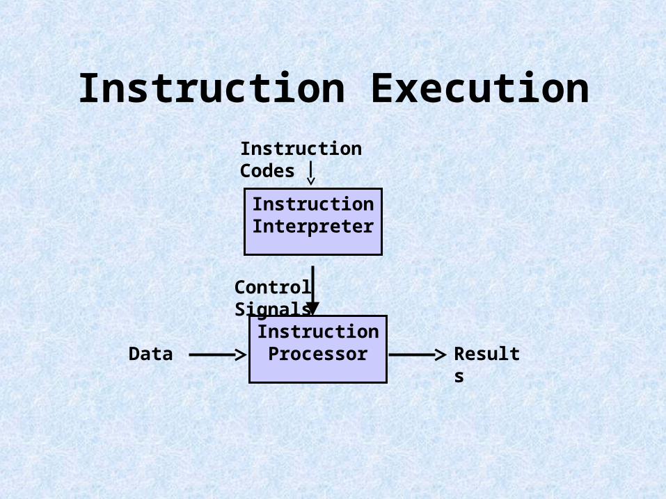
Instruction Execution
Instruction Processor
Instruction Interpreter
Control Signals
Instruction Codes
Data Results
Need of Memory
• Non-linear Programming Paradigm

Need of Memory
• Non-linear Programming Paradigm
• An operation on data may require more than one data value in a predetermined sequence
Need of Memory
• Non-linear Programming Paradigm
• An operation on data may require more than one data value in a predetermined sequence
• Speed of Input vs the speed of Processing Unit

Key Concepts of von Neumann Machine
• Data and Instructions in a single read-write Memory
Key Concepts of von Neumann Machine
• The contents of the memory addressable by location irrespective of the type of data stored.
Key Concepts of von Neumann Machine
• Sequential execution of instruction unless explicitly modifies by an instruction

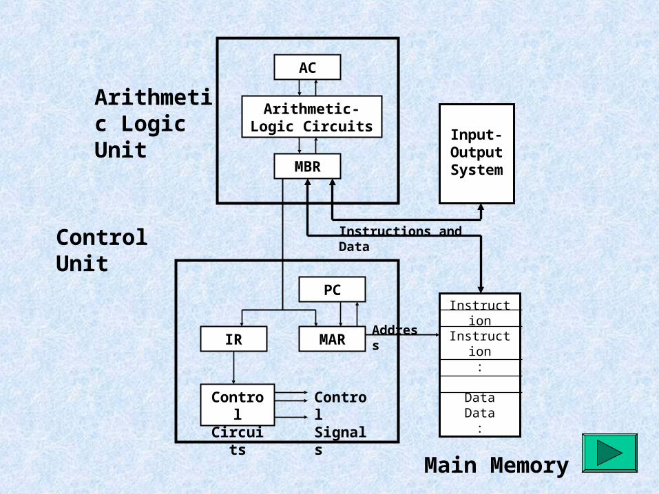
General Computer Structure
• Main Memory: For storing Data and Instruction
• Central Processing Unit: Consisting of Arithmetic-Logic Unit(ALU), Control Unit(CU), and Operational Registers
• Input and Output System: Operated by the Control Unit
Input-OutputSystem
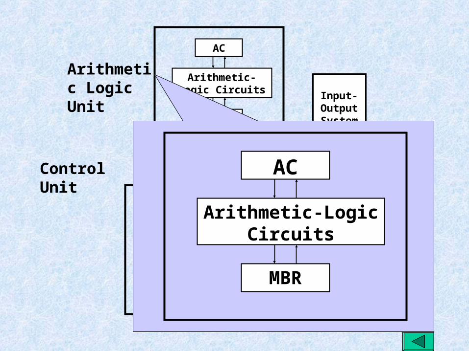
Arithmetic Logic Unit
Main Memory
InstructionInstruction
:
DataData:
PC
MARIR
MBR
Arithmetic-Logic Circuits
AC
Control Circuits
Control Signals
Address
Instructions and DataControl Unit
Input-OutputSystem
Main Memory
InstructionInstruction
:
DataData:
PC
MARIR
MBR
Arithmetic-Logic Circuits
AC
Control Circuits
Control Signals
Address
Instructions and Data
MBR
Arithmetic-Logic Circuits
AC
Arithmetic Logic Unit
Control Unit

Input-OutputSystem
Main Memory
InstructionInstruction
:
DataData:
PC
MARIR
MBR
Arithmetic-Logic Circuits
AC
Control Circuits
Control Signals
Address
Instructions and Data
PC
MARIR
Control Circuits
Control Signals
Arithmetic Logic Unit
Control Unit

Instruction Execution: An Example
Instruction Format:
Integer Format:
Opcode Address
0 3 4 15
S
0 1 15

Example Opcodes
1 Load AC from Memory 0001
2 Store AC to Memory 0010
3 Add to AC from Memory 0101

A typical Program statement Execution
0001 1001 1000 0000 0011 0000 0000
Address Contents
0101 1001 1000 0001 0011 0000 0001 0010 1001 1000 0001 0011 0000 0010
0000 0000 0000 0011 1001 1000 0000 0000 0000 0000 0010 1001 1000 0001
MEMORY CPU Registers
0011 0000 0000 PC
AC
0001 1001 1000 0000IR

So what are the key terms:
• The BInary digiT. BITs may be used for:– Representation of Opcode– Representation of Character data-ASCII (8bits),
unicode (16 bits)– Representation of Numeric data in binary form
• Integrated Circuits: For implementing electronics for data processing, storage and movement

The Macro Terms
• Byte, ASCII, Unicode
• Word
• ULSI
• GSI
• Microprocessors
• BUS
–The basic components of computer–The concepts of von Neumann
machine– Instruction execution with an example
and the role played by various components in instruction execution–Some of the basic terminology relating
to processors