Indicative Substation Layouts Diagrams - Planning … · Indicative Substation Layouts Diagrams ......
7
1 Indicative Substation Layouts Diagrams Appendix Q to the Response submitted for Deadline I Application Reference: EN010053 15 July 2015
Transcript of Indicative Substation Layouts Diagrams - Planning … · Indicative Substation Layouts Diagrams ......

1
Indicative Substation Layouts Diagrams Appendix Q to the Response submitted for Deadline I
Application Reference: EN010053
15 July 2015

Appendix Q: Indicative Substation Layouts Diagrams
The plans in the figures below are amalgamations of:
• Sheet 27 of 27 of the Onshore Works Plan (Doc ref No 5.2), to show the
Works Nos 7A & 7B, 8A & 8B, and 9A &8B;
• Figures 5.34a and 5.34b of Volume 3, Chapter 5: Landscape and Visual
Resources Part 2 of 3 of the ES (Doc ref No 7.3.5), to show the indicative
landscape plans;
• The figures located on pages 15 through 19 in Volume 4, Annex 4.3.7 of the
ES (Doc ref No 7.4.3.7), to show the various onshore substation layouts that
informed the Project’s Rochdale Envelope;
• Figure 1 of Appendix D of Volume 6, Annex 6.2.3: HVDC converter/HVAC
substation Flood Risk Assessment of the ES (Doc ref No 7.6.2.3), to show the
“proposed access road.”
Work 10 from the granted Hornsea Offshore Wind Farm (Zone 4) - Project One DCO is also shown on the plans. Work 10 is for that project’s “an electrical transmission station” according to its consented DCO. The coordinates of this Work can be found in that project’s Works Plan, but are also reproduced in the table, below.
Table 1 – Coordinates of Hornsea Offshore Wind Farm (Zone 4) - Project One’s Work 10 (OSGB36)
The intention of the various indicative onshore substation layouts, like the offshore WTG layouts, is to define the boundaries of the Rochdale Envelope. Alternative layouts are possible, and some alternative layouts have been designed by the Applicant to inform the size and shape of Work 8A and 8B, but are not presented in the ES because their impacts are always lesser than those that are presented.
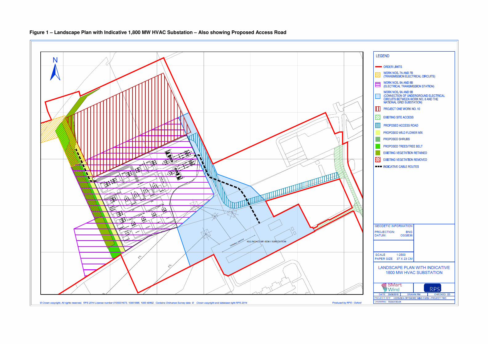
Figure 1 – Landscape Plan with Indicative 1,800 MW HVAC Substation – Also showing Proposed Access Road

Figure 2 - Landscape Plan with Indicative 1,800 MW HVDC Converter Station – Also showing Proposed Access Road
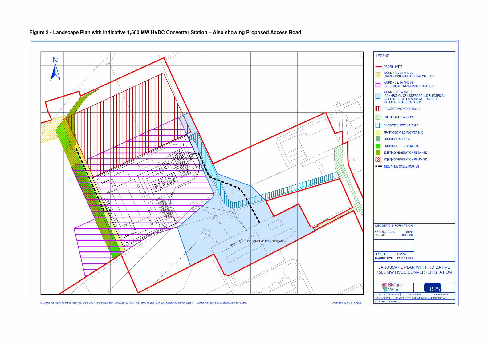
Figure 3 - Landscape Plan with Indicative 1,500 MW HVDC Converter Station – Also showing Proposed Access Road

Figure 4 - Landscape Plan with Indicative 900 MW HVAC Substation / 900 MW HVDC Converter Station (Layout 1) – Also showing Proposed Access Road

Figure 5 - Landscape Plan with Indicative 900 MW HVAC Substation / 900 MW HVDC Converter Station (Layout 2) – Also showing Proposed Access Road


![WELCOME [prod-]...Kitchen layouts are indicative only and subject to optimisation by Redrow Homes Limited. Colindale Gardens is a marketing name and will not necessarily form part](https://static.fdocuments.us/doc/165x107/5f1abca343c5a579fe1ebc4f/welcome-prod-kitchen-layouts-are-indicative-only-and-subject-to-optimisation.jpg)