1.substation layouts
39
SUB STATIONS
-
Upload
ayyadurai-shanmugam -
Category
Engineering
-
view
3.135 -
download
1
Transcript of 1.substation layouts

SUB STATIONS

Introduction Sub Stations are important link between
Generating stations and Distribution networks. They step down the EHV to HV as per the
requirement of the customers. Stability of the system, reliability of power
depends on the type of layout chosen and components used in the sub stations.
Hence great care has to be taken to select the layout and critical equipment for the SS.

~
Transmission line Yard in Receiving StationOut door yard in Generating Station
Out door yard in Generating station

Basic Requirements
Total land area & Ease of extension Soil condition & Soil resistivity Right of way for incoming and outgoing lines Facility to move heavy Equipments Load Centre System Security Operational Flexibility Simplicity of protection arrangement Ability to limit short circuit levels Maintenance Cost
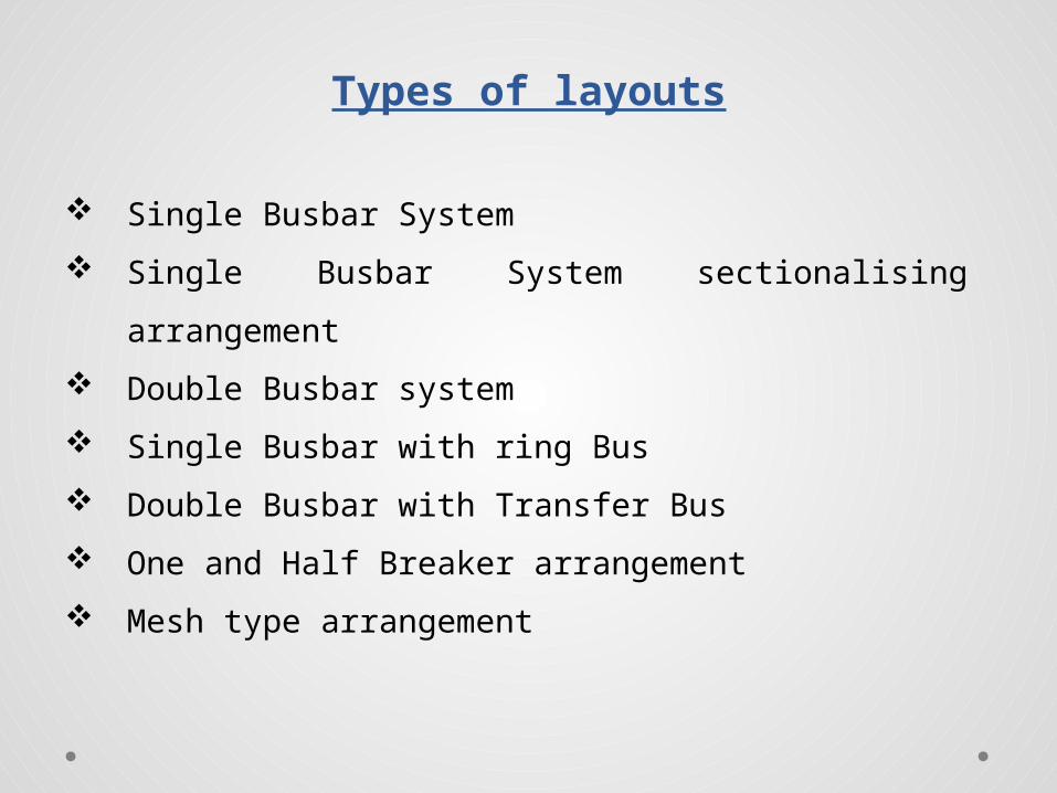
Types of layouts
Single Busbar System Single Busbar System sectionalising arrangement Double Busbar system Single Busbar with ring Bus Double Busbar with Transfer Bus One and Half Breaker arrangement Mesh type arrangement

Standard clearances
VOLTAGE PHASE TO PHASE PHASE TO EARTH
400 KV 4.000 Mtrs 3.50 Mtrs
230 KV 3.350 Mtrs 1.650 Mtrs
110 KV 1.675 Mtrs 1.000 Mtrs
66 KV 1.220 Mtrs 0.750 Mtrs
33 KV 0.915 Mtrs 0.610 Mtrs

Standard clearances
VOLTAGE CLEARANCE
GROUND CLEARANCE
SECTIONAL CLEARANCE
400 KV 8.000 Mtrs 10.000 Mtrs
230 KV 5.500 Mtrs 4.270 Mtrs
110 KV 4.600 Mtrs 3.350 Mtrs
66 KV 4.600 Mtrs 3.050 Mtrs
33 KV 3.650 Mtrs 2.750 Mtrs
22 KV 3.650 Mtrs 2.750 Mtrs
11 KV 3.650 Mtrs 2.600 Mtrs

Standard Bay Width
VOLTAGE BAY WIDTH
400 KV 27.000 Mtrs
230 KV 15.900 Mtrs
110 KV 9.500 Mtrs
66 KV 7.000 Mtrs
33 KV 4.600 Mtrs
22 KV 3.800 Mtrs11 KV 3.500 Mtrs

Single Busbar System
Single busbar with a sectionalizing arrangement can be erected to give more flexibility for operation and maintenance.
Single busbar with ring shaped bus can be Constructed for connecting many feeders from the substations.

Single Bus Scheme1

Single Busbar System
This system consists of a single bus to which various feeders are connected.
In case of a fault in bus / maintenance entire bus bar has to be shut down.
Provides least flexibility. Simple and most economical. This type of layout is adopted for Small and
Medium size Substations and Power stations.

Double Bus Scheme1

Double Busbar System Double Busbar system consists of two buses to which all the
feeders emanating from a substations, are connected by suitable switching arrangement.
Provides more flexibility, continuity of supply and periodical maintenance on the bus is also possible without Total shutdown.
In this arrangement the busbars are called Main and Reserve Busbars.
A Breaker can be introduced between the buses to have more operational flexibility.
A double busbar system with a Transfer bus are constructed to have more reliability and easy maintenance of Equipment.

Main & Transfer Bus Scheme1

Double Bus & Transfer Bus Scheme
1
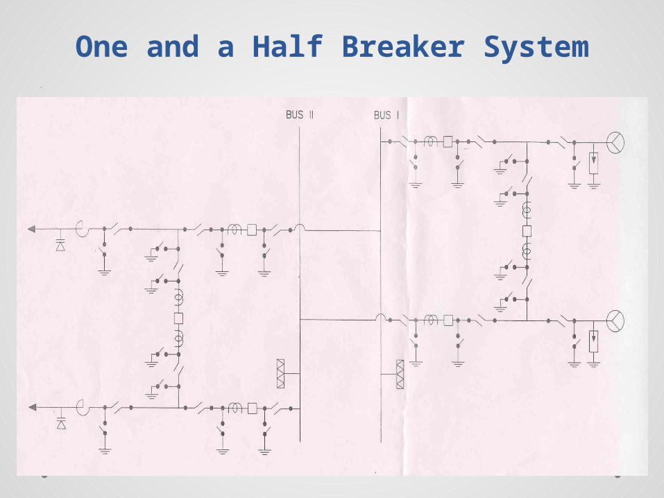
One and a Half Breaker System1

Double Busbar System
In this arrangement three circuit breakers are used to control two feeders
Any circuit breaker can be switched off without difficulty for maintenance works.
This system has high security against loss of supply. Suitable for switch yards of large Generating stations
handling large quantity of Power in individual circuits/feeders.
High cost but system security is very high.

Ring (Mesh) Bus Scheme1

Ring (Mesh) Bus Scheme
In this arrangement three circuit breakers are used to control two feeders
This type of layout is used to minimize the no of Breakers used in a Substation.
The breakers are connected in the mesh formed by the buses. The circuits are tapped from the node points of the Mesh.
Four breakers are utilized to control eight circuits. This arrangement is widely used in United Kingdom.
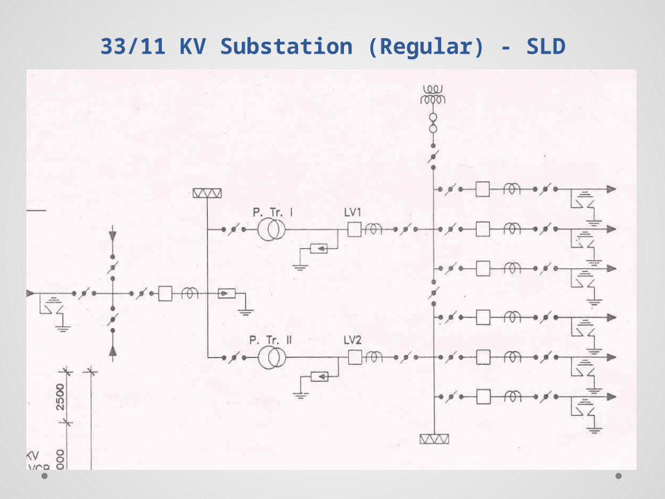
33/11 KV Substation (Regular) - SLD1

33/11 KV Substation (Regular) - Plan1

110/22 KV or 110/11 KV Substation - SLD1
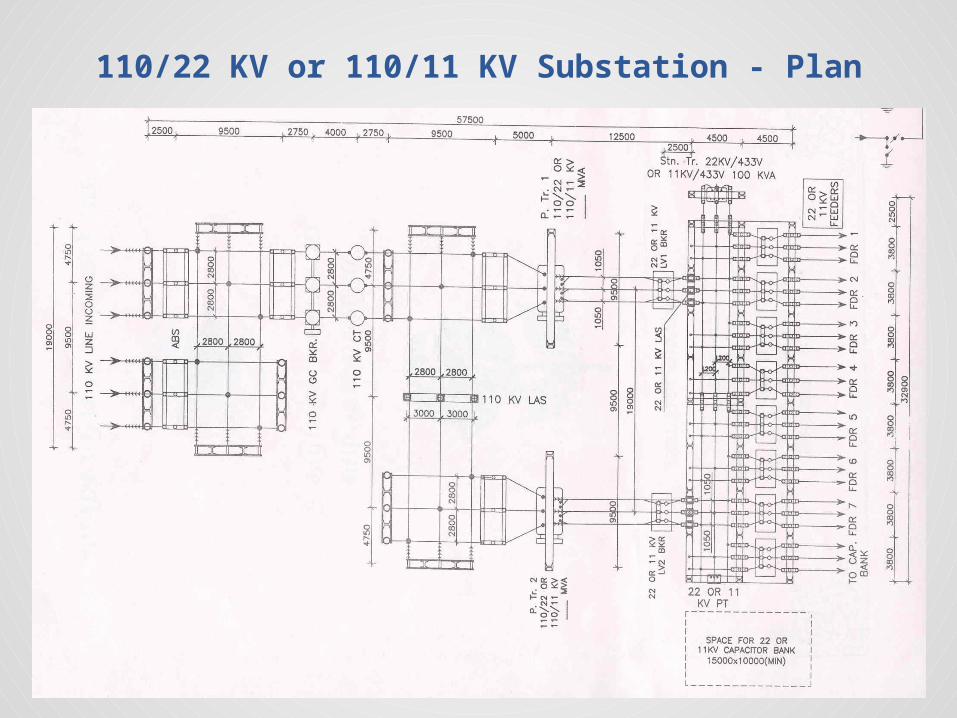
110/22 KV or 110/11 KV Substation - Plan1

230/ 110 KV Substation – SLD (Single Bus)1

230/ 110 KV Substation – Plan (Single Bus)1

230/ 110 KV Substation – Plan (Double Bus)1

230/ 110 KV SS – SLD (Main & Transfer Bus Scheme)
1

230/ 110 KV SS – Plan (Main & Transfer Bus Scheme)
1

230/ 110 KV SS – SLD (Double Bus Scheme)1

230/ 110 KV SS – Elevation (Double Bus Scheme)
1

400/230 KV SS – SLD (One and a Half Breaker System)
1

400/230 KV SS – Plan (One and a Half Breaker System)
1

Standard clearances in outdoor sub-stations1

Main Equipment in Substation Power/Auto Transformers, Circuit Breakers, Instrument Transformers, Surge Arresters, Control and Relay Panels, Station Batteries and Battery Chargers, DC and AC Panels, Control Cable, Isolators with and without Earthing Device, Capacitors, Reactors, Busbar materials, Insulators, Connecters etc.

Types of SS Transformer Substation: Transformer are installed to transform
power from one level to another as per needs. Switching Substations: This substation are erected for switching
operation of power lines with out transforming the voltage. Power factor correction Substation: This substation installed to
increase the power factor to minimize losses. Frequency Changer Substation: This substation installed where
speed controlled of motor required. Converting Substation: This substation convert A.C to D.C or vice
versa. Industrial Substation: This substation installed for supply power
only to industry.
Types of SS Paralleling sub station. The SS where power from
different source of generation are paralleled. Two system has to get connected (parallel), synchronizing facility needed .
Must have reliable Communication with Load dispatcher and generating stations.
Double bus with a transfer bus arrangement will be most ideal type of layout
Major receiving station : The power handled by the station is high.
One and a half breaker layout will be suitable. Reliable communication, duplicated protection system, Spare
capacity of Auto transformer , good security in system are needed.

Generating station layout Depends on the Nos of generator in the station. Should have a layout which should not affect generation even one unit is
shut down Double bus with transfer bus is most suitable. However a single bus
scheme with two feeders can be considered for a station with single generating unit
Should have reliable communication with Load dispatcher and receiving station.
Located adjacent to the power house. Indoor / outdoor AISS or GISS are generally considered suitable for major
generating stations. In under ground power generating stations transformer yard is located near
the generators and the EHV is taken thru EHV cables to the outdoor yard.

Main Equipment in Substation
Selection of right type of Layout, Equipments of adequate ratings and correct Protection system will make the Power system Safe, Secure and also give operational Flexibility.


![Report on Ichchhapore substation Substation...2014/07/06 · Date:02/02/2018 Report on Ichchhapore substation Substation: SubstationEquipment: 1] PowerTransformer: A ...](https://static.fdocuments.us/doc/165x107/6082a7423c38c8542368e070/report-on-ichchhapore-substation-substation-20140706-date02022018-report.jpg)