Indian Standard FUNCTIONAL SAFETY OF ELECTRICAIJ...
59
lS/lEC 61508-1:1998 W?7%7mlm raqrr/<[email protected]’lwilJq @hfiRcb Fjj5!3r-?%kfl T7Cll * *I ~iwcb VW ml ?TFll=4al’aHrij Indian Standard FUNCTIONAL SAFETY OF ELECTRICAIJ ELECTRONIC/PROGRAMMABLE ELECTRONIC SAFETY-RELATED SYSTEMS PART 1 GENERAL REQUIREMENTS ICS 13.1 10; 25.040; 29.020; 35.240.50 @ BIS 2008 BUREAU OF INDIAN STANDARDS MANAK BHAVAN, 9 BAHADUR SHAH ZAFAR MARG NEW DELHI 110002 October 2008 Price Group 14
Transcript of Indian Standard FUNCTIONAL SAFETY OF ELECTRICAIJ...

Ill II1. . ..&.~— .. —,.. . . ,.-.—... ..— ————
f.. ~-b’-- ‘: [):-’’”’: $)
., —.._.—..— ... .
lS/lEC 61508-1:1998
W?7%7mlm
raqrr/<[email protected]’lwilJq @hfiRcb Fjj5!3r-?%kfl T7Cll
* *I ~iwcb VW
ml ?TFll=4al’aHrij
Indian Standard
FUNCTIONAL SAFETY OF ELECTRICAIJELECTRONIC/PROGRAMMABLE ELECTRONIC
SAFETY-RELATED SYSTEMS
PART 1 GENERAL REQUIREMENTS
ICS 13.1 10; 25.040; 29.020; 35.240.50
@ BIS 2008
BUREAU OF INDIAN STANDARDSMANAK BHAVAN, 9 BAHADUR SHAH ZAFAR MARG
NEW DELHI 110002
October 2008 Price Group 14

WEC 61508-1:1998
CONTENTS
Page
clalJse
1 Scope1
.......... .. ..... .................. ......... .. .. .. ......... ...... ....... .... .. .... .. ......... ............ .......... ...... ...
2 Normative references ................. .... .. ..... ......... ........ ... ..... ..... .......... ... ....... .... ... ... ... ..........3
3 Definitions and abbreviations . ..... ... .. ......4.......... .. ............ .... ............ ........ ..... .... ....... ....... .
4 Conformance to this standard ..... ... .. ... ............ ..4.............. .... .......... .. .. ........... ..... . .. .... .......
5 Documentation.. ..................... ........ .. ... ........... ............ .... . .. .. ............ ........ .. .. ..... .... .......... 5
5.1 Objectives5.. ... ........... ............. . ... ........... ..... ............. ... .... ....... ... ........ ... ...... ........”....
5.2 Requirements6.............. ..... .. .. . ... ... ........ ................. .... ............ ... ......... ...... .. .... .......
6 Management of functional safety ..... .7. ............ .... ............!.... .. .......... ... ......... ..... .. ...... .... ..
6.1 Objectives . ................ .......... .. . ... .......... ...... ........ .... ..... .......... .. .. ........ ...... .. ............ . 7
6.2 Requirements ................... .... . ... ........... .... ............... .................. ....... ....... ... ...........7
7 Overall safety Iifecycle requirements ... .......... .... ......... .... .... ............ ........... ...... .... ...... .. ... 9
7.1
7.2
7.3
7.4
7.5
7.6
7,7
70
7.9
7.10
7.11
7.12
7’.13
7.14
7.15
7.16
7.17
7,18
General ..................... ............ .. ............. ..... ........ ... .... ......... ... .... ....... ....... .....”.... .... 9
Concept. . ....... .......... . ...,,,, ... .,.,, . .......... ..... ...... ....... ... ........... .... ............... .............. 17
Overali scope definition .... ..... .. .. ........... .... .............. ................ .. ........ ........ ...... ... .... 18
Hazard and risk analysis ....... . .. .. ... ...... .... ...... 18.... ... ... ................. ........ ....... ..... ........
Overall safe! y requirements ... . .. ............................................................................2O
Safety requirements allocation .. ........... ... .. ............. ................ .......... ....... ..............22
Overa.11 operation and maintenance planning . ..... .. .. .... ............ ......... ..... ...... ........ 28
C)verall safety validation p!anning ......... ... . ........ ..... .. .............. .......... .. ... ... ............. 29
Overall installation and commissioning planning ...... .. ............. ........ ... ...... ....... .......3O
Flealisation: E/E/12ES ... ..... ... ... .. ... ........ ... .. ............ ... .... ...... ... ..... ....... ..................... 31
Realisation: other technology . . .. ........ . . .. . ...... ...... ... .......... .. ............ ........ ..... .. ....3l
Realisation: external risk reduction facilities . .... .. .... .............. ............ ....... .............31
Overall installation and commissioning ..... ......... ..... ... ............. .. ....... .. ...... ......... .... 32
Overall safety validation ........ . .. .... ........ ..... ...... .. ... ... .......... ..... ........ ..... .. ..... .......32.,
Overall operation, maintenance arid repair ......... ...... ... .......... ..... ....... ........ .. .... .....33
Overall modification and retrof it.. ....... .... ........... ...... ... ............. .......... ..... .. ............ 36
Decommissioning or disposal ...,.... .. .... .. .. ............. .... ............”... ....... ..... .. ....... ......38
Veriflcatlon ................... ...... . ... .. . . . ..... ... ................. .... .......... .......... ........ .............39
8 Functional safety assessment ...... .. .. ..... ........ ........... ...... ............... ........ ... ...... .. .... .. ......39
8.1 Objective .................. ......... .. ... . .. .. ........ .... ......... ..... . .. ............. ........ .. ...... .. ....... .....40
8.2 Requirements ........... ....... ,,, . .. .... . ..~... ... ...... ..... .. .. ... ................. ........ .... .. ...... .......40

KYIEC 61508-1:1998
Annexes
Annex A [informative) Example documentation structu re ......... .................43
A.1 General ...... .... .. ............ ....... ..... ...... ............. ......... .... ...... ........ ...... .......... .............. 43
A.2 Safety Iifecycle document structure .... ........... ........... ....... .. ....... ..... .. ........ ......... ..... 44
A.3 Physical document structure ..... ...... ............ .... ...... .......... ....... ....... .......... ............. 44
A.4 List of documents ............... ..... ......... ............ ........... ....... ....... ......... .......... ............. 49
Annex B (informative) Competence of persons ........... .. .......... ....... .............. ........ .. .. .. .......... 50
B.1 Objective ......... ............................... ................... ....... ..... ................. ....... .. ....... ...... 50
B.2 General considerations .... .............. .............. .... . ........ ...... ............. ........... ... ... ...... 50
Annex C (informative) Bibliography ............... ................................. .. ... ........ . ........ ............... 51
Tables
1 Overall safety lifecycle: overview .................. ........................................ ........... ..... ......... 13
2 Safety integrity levels: target failure measures for a safety function, allocated toan E/E/PE safety-related system operating in low demand mode of operation ................ 26
3 Safety integrity levels: target failure measures for a safety function, allocated toan E/E/PE safety-related system operating in high demand or continuous modeof operation .. ....... ..... ................ ....... ................................ .. ............................. ........ ....... 26
4 Minimum levels of independence of those carrying out functional safety assessment(overall safety Iifecycle phases 1 to 8 and 12 to 16 inclusive (see figure 2)) ..... .............42
5 Minimum levels of independence of those carrying out functional safety assessment(overall safety Iifecycle phase 9- includes all phases of E/E/PES and software safetyIifecycles (see figures 2, 3 and 4)) .......... ... .......... .......... ......... ........ .............. ... ....... ...... 42
A.1 Example documentation structure for information related to the overallsafety lifecycle .... .... . ............. ... .......... ......... ......... .......... ....... ................ .. ....... .. ...... ...... 45
A.2 Example documentation structure for information related to the E/E/PESsafety lifecycle .... ... .. ........................................... .................... ....... ............... .. ...... ....... 46
A.3 Example documentation structure for information related to the softwaresafety lifecycle ..... .. ... ..................... ......... .......... ....... ........ ....... ............. .......... ......... ..... 47
Figures
1 Overall framework of this standard ................... ......... .... .. ....... ... ....... ...... ...... ... ........ ..... 3
2 Overall safety lifecycIe ............ .. .............. .............. ............ ....... ........ ....... ........ . ....... ....... 10
3 E/E/PES safety lifecycle (in realisation phase) .............. ............ ............. ........ ... ....... ..... 11
4 Software safety lifecycle (in realisation phase) ...... .... ............. .... ........... ........ .. ......... ...... 11
5 Relationship of overall safety Iifecycle to E/E/PES and software safety Iifecycles ........... 12
6 Allocation of safety requirements to the E/E/PE safety-related systems,other technology safety-related systems and external risk reduction facilities .. ... ...... ...... 25
7 Example operations and maintenance activities model ............... ........... .......... . .. ..... .. .... 35
8 Example operation and maintenance management model ........ ............. .. ........ . ....... ....... 36
9 Example modification procedure model .. .......... ..... ........ ... ............. ........ ........ .... ...... ...... 38
A.1 Structuring information into document sets for user groups ................... ......... .......... ..... 48
A.2 Structuring information for large complex systems and small lowcomplexity systems 48.. .............. ............... .............. ....... . ..... ..... .... .......... ......... .. .......... ...
ii

lS/lEC 61508-1:1998
Industrial Process Measurement and Control Sectional Committee, ETD 18
NATIONAL FOREWORD
This Indian Standard (Part 1) which is identical with IEC 61508-1 : 1998 ‘Functional safety ofelectrical/electron ic/programmable electronic safety-related systems — Part 1: General requirements’issued by the International Electrotechnical Commission ([EC) was adopted by the Bureau of IndianStandards on the recommendation of the industrial Process Measurement and Control SectionalCommittee and approval of the Electrotechnical Division Council.
The text of IEC Standard has been approved as suitable for publication as an Indian Standard withoutdeviations. Certain conventions are, however, not identical to those used in Indian Standards.Attention is particularly drawn to the following:
a) Wherever the words ‘International Standard’ appear referring to this standard, they shouldbe read as ‘Indian Standard’.
b) Comma (,) has been used as a decimal marker, while in Indian Standards, the currentpractice is to use a point (.) as the decimal marker.
In this adopted standard, references appear to certain International Standards for which IndianStandards also exist. The corresponding Indian Standards, which are to be substituted in theirrespective places, are listed below along with their degree of equivalence for the editions indicated:
International Standard
IEC 61508-2 : 2000 Functional safetyof electrical/electronic/programmableelectronic safety-related systems —Fart 2: Requirements for electrical/electronic/programmable electronicsafety-related systems
IEC 61508-3 : 1998 Functional safetyof electrical/electronic/programmableelectronic safety-related systems —Part 3: Software requirements
IEC 61508-4 : 1998 Functional safetyof electrical/electronic/programmableelectronic safety-related systems —Part 4: Definitions and abbreviations
IEC 61508-5 : 1998 Functional safetyof electrical/electronic/programmableelectronic safety-related systems —Part 5: Examples of methods for thedetermination of safety integrity levels
IEC 61508-6 : 2000 Functional safetyof electrical/electronic/programmableelectronic safety-related systems —Part 6: Guidelines on the application ofIEC 61508-2 and IEC 61508-3
Corresponding Indian Standard
ISAEC 61508-2 : 2000 Functional safety ofelectrical/electronic/programmable electronicsafety-related systems: Part 2 Requirementsfor electrical/ electronic/programmableelectronic safety-related systems
lS/lEC 61508-3 : 1998 Functional safety ofelectrical/electron ic/programmable electronicsafety-related systems: Part 3 Softwarerequirements
lS/l EC 61508-4 : 1998 Functional safety ofelectrical/electron ic/programmable electronicsafety-related systems: Part 4 Definitionsand abbreviations
lS/l EC 61508-5 : 1998 Functional safety ofelectrical/electron ic/programmable electronicsafety-related systems: Part 5 Examples ofmethods for the determination of safetyintegrity !evels
lS/lEC 61508-6 : 2000 Functional safety ofelectrical/electronic/programmable electronicsafety-related systems: Part 6 Guidelines onthe application of IEC 61508-2 and IEC61508-3
Degree ofEquivalence
Identical
do
do
do
do
...Ill

ISIIEC 61508”1:1998
!cierna!iona] Standard
IEC 61508-7 : 2000 Functional
Corresponding indian Standard
safetv lS/lEC 61508-7 : 2000 Functional safetv
Degree ofEquivalence
of Identicalof el.sctrical/electroriic/rxoarammable electrical/electronic/ programmable electr&ic~slectroflic safety-related +sterm — safety-related syst%:- Part ‘7 Overview ofpafi ~: @ewiew of techniques and techniques and measuresmeasures
iSO/l EC Guide .51 : 19901) Guidelines lS/iSO/lEC Guide 51 : 2005 Safety aspects Technicallyfcr the inclusion of safety aspects in -– Guidelines for the inclusion in standards Equivalent‘>tandads
The technical committee has reviewed the provisions of the following International Standard referredm !his adopted standard and has decided that it is acceptable for use in conjunction with thisstandard:
International .Sfandard Title
li?C Guide 104:1997 Guide to the drafting of safety standards and the role of Committees withsafety pilot functions and safety group functions
CM!y the English language text k the International Starldard has been retained while adopting it in thisirld,an Standard, and as such the page nu~bers given here :ire not the same as in the IEC Standard.
For the p~lrpose <If deciding whether a particular requirement of this standard is complied with, the
finai value, observecf or calculated, expressing the result of a test, shall be rounded off in accordancewith IS 2 : 1!36@‘Rules for rounding off numerical values (revised)’. The number of significant placesretained in the rounded off value should be the same as that of the specified value in this standard.
lS/lEC 61508-1:1998
INTRODLJCTION
Systems comprised of electrical and/or electronic components have been used for many years:c) perform safety functions in most application sectors. Computer-based systems (genericallylo ferred to as programmable electronic systems (P ES S)) are being used in all application:iec.tors to perform non-safety functions and, l~cr~i~sirlgly, to perform safety functions, If:,:amputer system technology is to be effectively and safely exploited, it is essential that thoseresponsible for making decisions have sufficient guidance on the safety aspects on which tomake these decisions.
Th:s !nternation”al Standard sets out a generic approach for all safety Iifecycle activities for~y~tems ~o~,pfi~~d of electrical and/or electronic and/or programmable electronic components
(elect rical/electron ic/programmable electronic systems (E/E/P ESs)) that are used to performsafety functions. This unified approach has been adopted in order that a rational and consistenttechnl{:nl pollcy be developed for all electrically-based safety-related systems. A major
objective IS to fac~litate the development of application sector standards.
,p vl~~: stf~ati~r-1~, safety is achieved by a ni.,imber of protective systems which rely on many[c:- ~nr>k~gies (for example mechanical, hydraulic, pneumatic, electrical, electronic, programmable“>:[.~;:rc!rl!c). Any safety strategy must therefore consider not only all the elements within an“(j v~d~,a’ system (for example sensors, controlling devices and actuators) but also all the:.,,]!c!y-related systems making up the tmal combination of safety-related systems. Therefore,\%!l!!f? :h[s International Standard is concerned with electrical/electronic/programmable~~e{;trorlic (E/E/PE) safety-related systems, It may also provide a framework within whichsafety-related systems based on other technologies may be considered.
~~,:$ recognized that there is a great variety of E/E/PES applications in a variety of applicationsectors and covering a wide range of complexity, hazard and risk potentials. In any particularapplication. the required safety measures will be dependent on many factors specific to theapplication. This International Standard, by being generic, will enable such measures to beformulated in future application sector international standards.
This International Standard
. considers all relevant overall, E/E/PES and software safety Iifecycle phases (for example,from initial concept, through design, irnplementation, operation and maintenance todecommissioning) when E/E/PESs are used to perform safety functions;
– has been conceived with a rapidly developing technology in mind; the framework issufficiently robust and comprehensive to cater for future developments;
— enables application sector international standards, dealing with safety-related E/E/PESs, tobe developed; the development of application sector international standards, within theframework of this standard, should lead to a high level of consistency (for example, ofunderlying principles, terminology etc. ) both within application sectors and acrossapplication sectors; this will have both safety and economic benefits;
– provides a method for the development of the safety requirements specification necessaryto achieve the required functional safety for E/E/PE safety-related systems;
v

lS/lEC 61508-1:1998
— uses safety integrity levels for specifying the target level of safetyfunctions to be implemented by the E/E/PE safety-related systems;
— adopts a risk-based approach for the determination of therequirements;
integrity for the safety
safety integrity level
. sets numerical target failure measures for E/E/PE safety-related systems which are linkedto the safety integrity levels;
— sets a lower limit on the target failure measures, in a dangerous mode of failure, that canbe claimed for a single E/E/PE safety-related system; for E/E/PE safety-related systemsoperating in
.— a low demand mode of operation, the lower limit is set at an average probability offailure of 10-5 to perform its design function on demand,
-. a high demand or continuous mode of operation, the lower limit is set at a probability ofa dangerous failure of 10–9 per hour;
NOTE - A single E/E/PE safety-related system does not necessarily mean a single-channel architecture.
— adopts a broad range of principles, techniques and measures to achieve functional safetyfor E/E/PE safety-related systems, but does not use the concept of fail safe which may beof value when the failure modes are well defined and the level of complexity is relativelylow. The concept of fail safe was considered inappropriate because of the full range ofcomplexity of E/E/PE safety-related systems that are within the scope of the standard. ~
vi

lS/lEC 61508-1:1998
Indian Standard
FUNCTIONAL SAFETY OF ELECTRICALELECTRC)NIC/PROGRAMMABLE ELECTRONIC
SAFETY-RELATED SYSTEMS
PART 1 GENERAL REQUIREMENTS
1 scope
1.1 This International Stand-ard covers those aspects to be considered whenelectrical/e lectronic/program mable electronic systems (E/E/PESs) are used to carry out safetyfunctions. A major objective of this standard is to facilitate the development of applicationsector international standards by the technical committees responsible for the applicationsector. This will allow all the relevant factors, associated with the application, to be fully taken(nto account and thereby meet the specific needs of the application sector. A dual objective oft17is standard is to enable the development of elect rical/elect ronic/programmable electronic(E/E/PE) safety-related systems where application sector international standards may not exist.
‘1.2 In particular, this standard
a) applies to safety-related systems when one or more of such systems incorporateselect rical/electronic/p rogrammable electronic devices;
tJO~~ : – In the context of low complexity E/E/PE safety-related systems, certain requirements specified in thisstandard may be unnecessary, and exemption from compliance with such requirements is possible (see 4.2, and
the d:~inition of a low complexity E/E/PE safety-related system In 3.4.4 of IEC 61508-4),
NOTE 2 . Although a person can form part of a safety-related system (see 3.4.1 of IEC 61508-4), human factor
req~Jlrements related to the design of E/E/PE safety-related systems are not considered in detail in this standard.
b)
c)
d)
e)
is generically-based and applicable to all E/E/PE safety-related systems irrespective of the
application; 1,
covers possible hazards caused by failures of the safety functions to be performed byEIE/PE safety-related systems, as distinct from hazards arising from the E/E/PE equipmentitself (for example electric shock et:);
does not cover E/E/PE systems where
– a single E/E/PE system is capable of providing the necessary risk reduction, and
– the required safety integrity of the E/E/PE system is less than that specified for safetyintegrity level 1 (the lowest safety integrity level in this standard).
is mainly concerned with the E/E/PE safety-related systems whose failure could have animpact on the safety of persons and/or the environment; however, it is recognized that theconsequences of failure could also have serious economic implications and in such casesthis standard could be used to specify any E/E/PE system used for the protection ofequipment or product;
1) Applies to French text only. 1

IWEC 61508-1:1998
f) considers E/E/PE safety-related systems, other technology safety-related systems andexternal risk reduction facilities in order that the safety requirements specification for theE,@’PE safety-related systems can be determined in a systematic, risk-based manner;
g) uses an overall safety Iifecycle model as the technical framework for dealing systematicallywith the actwities necessary for ensuring the functional safety of the E/E/PE safety-relatedsystems;
NCTE 3- The early phases of the overall safety Iifecycle include, of necessity, consideration of other technology(as well as the E/E/PE safety-related systems) and external risk reduction facilities, in order that the safetyrequirements specification for the E/E/PE safety-related systems can be developed in a systematic, risk-basedmanner,
N(3TE 4 - Although the overall safety Iifecycle is primarily concerned with E/E/PE safety-related systems, it couldd!o provide a technical framework for the consideration of any safety-related system irrespective of the technologycf that system (for example mechanical, hydraulic or pneumatic).
h) does not specify the safety integrity levels required for sector applications (which must bebased on detailed information and knowledge of the sector application). The technicalcommittees responsible for the specific application sectors shall specify, where appropriate,the safety integrity levels in the application sector standards;
/) provides general requirements for E/E/PE safety-related systems where no applicationsector standards exist;
j) does not cover the precautions that may be necessary to prevent unauthorized personsdamag~ng, and/or otherwise adversely affecting, the functional safety of E/E/PE safety-related systems.
f.3 This part of IEC 61508 specifies the general requirements that are applicable to all parts.other parts of IEC 61508 concentrate on more specific ‘topics:
-- parts 2 and 3 provide additional and specific requirements for E/E/PE safety-relatedsystems (for hardware and software);
– part 4 gives definitions and abbreviations that are used throughout this standard;
- part 5 provides guidelines on the application of part 1 in determining safety integrity levels,by showing example methods;
-- part 6 provides guidelines on the application of parts 2 and 3;
- part 7 contains an overview of techniques and measures.
1.4 Parts 1, 2, 3 and 4 of this standard are basic safety publications, although this status doesnot apply in the context of low complexity E/E/PE safety-related systems (see 3.4.4 of part 4).As basic safety publications, they are intended for use by technical committees in thepreparation of standards in accordance with the principles contained in IEC Guide 104 andlSO/l EC Guide 51. One of the responsibilities of a technical committee is, wherever applicable,to make use of basic safety publications in the preparation of its own publications. IEC 61508 isalso intended for use as a stand-alone standard.
NOTE – In the USA and Canada, until the proposed process sector implementation of IEC 61508 is published as aninternational standard in the USA and Canada, existing national process safety standards based on IEC 61508 (i.e.ANS1/l SA S84.01 -1 996) (see reference [8] in annex C) can be applied to the process sector instead of IEC 61508.
1.5 Figure 1 shows the overall framework for parts 1 to 7 of IEC 61508 and indicates the rolethat IEC 61508-1 plays in the achievement of functional safety for E/E/PE safety-relatedsystems.
2

lS/lEC 61508-1:1998
t “mDevelopment of the overall safety ~
requirements (concept, scopedefinition, hazard and risk analysis)(E/E/PEsafety-relatedsystems,other ~
technology safety-relatectSwtem and Risk baS& approachedexternal risk reductionfacilities) to the development of
7.1 to 7.5 the safaty integrity
I requirements
IAllocation of the safety
requirements to the E/E/PEsafety-related systams
I
7.6
Installation and commissioningand safety validation of E/EIPE
safety-related systems
I 7.13 and 7.14 II
I IOperation and maintenance,
modification and retrofit,decommissioning or disposal ofEIEIPE safety-related systems
1 7.15 t07.171
/Other\
I Definitiona andabbreviations I
II Documentation
I
mI Clausa 6
IFunctional safetyassessment
I
I Clause 8
Figure 1 – Overall framework of this standard
3

lS/lEC 61508-1:1998
2 Normative references
The following normative documents contain provisions which, through reference in this text,constitute provisions of this part of IEC 61508. For dated references, subsequent amendmentsto, or revisions of, any of these publications do not apply. However, parties to agreementsbased on this part of IEC 61508 are encouraged to investigate the possibility of applying themost recent editions of the normative documents indicated below. For undated references, thelatest edition of the normative document referred to applies. Members of IEC and ISO maintainregisters of currently valid international standards
1S0/1 EC Guide 51:1990, Guidelines for the inc/usion of safety aspects in standards
IEC Guide 104:1997, Guide to the drafting of safety standards, And the ro/e of Committees withsafety pi/et functions and safety group functions
IEC 61508-2, — Functional safety of electrical/electronics//programmab/e electronic safety-related systems – Part 2.” Requirements for electrical/electronical/programmable electronicsafety-re/ated systems 1)
IEC 61508-3:1998, Functional safety of e/ectrica//electronica//programmable electronic safety-related systems – Part 3.. Software requirements
IEC 61508-4:1998, Functional safety of electrical/e/ectronical/programmable electronic safety-related systems – Part 4.- Definitions and ‘abbreviations
IEC 61508-5:1998, Functional safety of electrical/electronical/programmable electronic safety-related systems – Part 5: Examples of methods for the determination of safety integrity levels
\EC 61508-6, — Functional safety of electrical/electronical/programmable electronic safety-reiated systems – Part 6: Guidelines on the application of parts 2 and 3 1)
IEC 61508-7, — Functional safety of electrica//electronical/programmable electronic safety-re/ated systems – Part 7: Overview of techniques and measures 2)
3 Definitions and abbreviations
For the purposes of this standard, the definitions and abbreviations given in part 4 apply.

lS/lEC 61508-1:1998
4 Conformance to this standard
4.1 To conform to this standard it shall be demonstrated that the requirements have beensatisfied to the required criteria specified (for example safety integrity level) and therefore, foreach clause or subclause, all the objectives have been met.
NOTE -- It is not generally possible to single out any one factor that determines the degree to which a requirementis to be satisfied (degree of rigour). It will be dependent upon a number of factors which, themselves, may dependupon the specific overall, E/E/PES or software safety Iifecycle phase and activity. The factors will include:
— consequence and risk reduction;
nature of the hazards;
— safety integrity level;
– type of implementation technology;
– size of systems;
— number of teams involved;
– physical distribution;
— novelty of design.
4.2 This standard specifies the requirements for E/E/PE safety-related systems and has beendeveloped to meet the full range of complexity associated with such systems. However, for lowcomplexity E/E/PE safety-related systems (see 3.4.4 of IEC 61 508-4), where dependable fieldexperience exists which provides the necessary confidence that the required safety integritycan be achieved, the following options are available:
— in application sector standards implementing the requirements of IEC 61508-1 toIEC 61508-7, certain requirements may be unnecessary and exemption from compliancewith such requirements is acceptable;
— if this standard is used directly for those situations where no application sector internationalstandard exists, certain of the requirements specified in this standard may be unnecessaryand exemption from compliance with such requirements is acceptable providing this isjustified.
4.3 Application sector international standards for E/E/PE safety-related systems developedwithin the framework of this standard shall take into account the requirements of lSO/lECGuide 51 and IEC Guide 104.
5 Documentation
5.1 Objectives
5.1.1 The first objective of the requirements of this clause is to specify the necessaryinformation to be documented in order that all phases of the overall, E/E/PES and softwaresafety Iifecycles can be effectively performed.
5

-—. - .—.. ..__,._
lS/lEC 61508-1:1998
.,.——.——.
5.1.2 The second objective of the requirements of this clause is to specify the necessaryinformation to be documented in order that the management of functional safety (see clause 6),verification (see 7.1 8) and the functional safety assessment (see clause 8) activities can beeffectively performed.
NOTE 1 – The documentation requirements in this standard are concerned, essentially, with information rather thanphysical documents. The Information need not be contained in physical documents unless this is explicitly declaredIn the relevant subclause.
NOTE 2 – Documentation may be available in different forms (for example on paper, film, or any data medium to bepresented on screens or displays).
NOTE 3 – See annex A concerning possible documentation structures.
NOTE 4 – See reference [4] in annex C.
5.2 Requirements
5.2.1 The documentation shall contain sufficient information, for each phase of the overall,E/E/PES and software safety Iifecycles completed, necessary for effective performance ofsubsequent phases and verification activities.
NOTE – What constitutes sufficient information will be dependent upon a number of factors, including thecomplexity and size of the E/E/PE safety-related systems and the requirements relating to the specific application.
5.2.2 The documentation shall contain sufficient information required for the management offunctional safety (clause 6).
NOTE – See notes to 5.1.2.
5.2.3 The documentation shall contain sufficient information required for the implementationof a functional safety assessment, together with the information and results derived from anyfunctional safety assessment.
NOTE – See notes to 5.1.2,
5.2.4 Unless justified in the functional safety planning or specified in the application sectorstandard, the information to be documented shall be as stated in the various clauses of thisstandard.
5.2.5 The availability of documentation shall be sufficient for the dutiesrespect of the clauses of this standard.
NOTE – Only the information necessary to ,Indertake a particular activity, required by thisby each relevant party.
5.2.6 The documentation shall
– be accurate and concise;
– be easy to understand by those persons having to make use of it;
— suit the purpose for which it is intended;
– be accessible and maintainable.
5.2.7 The documentation or set of information shall have titles or names
to be performed in
standard, need be held
indicating the scooeof the contents, and some form of index arrangement so as to allow ready ac~ess to theinformation required in this standard.
5.2.8 The documentation structure may take account of company procedures and the workingpractices of specific application sectors.
5.2.9 The documents or set of information shall have a revision index (version numbers) tomake it possible to identify different versions of the document.
6

lS/lEC 61508-1:1998
5.2.10 The documents or set of information shall be so structured as to make it possible tosearch for relevant information. It shall be possible to identify the latest revision (version) of adocument or set of information.
NOT E -- The physical structure of the documentation will vary depending upon a number of factors such as the s:zeof il~? system, Its complexity and organizational requirements,
5.2.11 All relevant documents shall be revised, amended, reviewed, approved and be under
the control of an appropriate document control scheme.
NOTE --- Where automatic or semi-automatic tools are used for the production of documentation, specificprocedures may be necessary to ensure effective measures are in place for the management of versions or othercontrol aspects of the documents.
6 Management of functional safety
6.1 Objectives
6.1.1 The first objective of the requirements of this clause is to specify the management andtechnical activities during the overall, E/E/PES and software safety Iifecycle phases which arenecessary for the achievement of the required functional safety of the E/E/PE safety-relatedsystems.
6.1.2 The second objective of the requirements of this clause is to specify the responsibilitiesof the persons, departments and organizations responsible for each overall, E/E/PES andsoftware safety Iifecycle phase or for activities within each phase.
NOTE - The organizational measures dealt with in this clause provide for the effective implementation of thetechnical requirements and are solely aimed at the achievement and maintenance of functional safety of the E/E/PEsafety-related systems. The technical requirements necessary for maintaining functional safety WIII normally bespecified as part of the Information provided by the supplier of the E/E/PE safety-related system
6.2 Requirements
6.2.1 Those organizations or individuals that have overall responsibility for one or morephases of the overall, E/E/PES or software safety Iifecycles shall, in respect of those phasesfor which they have overall respo~sibility, specify all management and technical activities thatare necessary to ensure that the E/E/PE safety-related systems achieve and maintain therequired functional safety. In particular, the following should be considered:
a) the policy and strategy for achieving functional safety, together with the means forevaluating its achievement, and the means by which this is communicated within theorganization to ensure a culture of safe working;
b) identification of the persons, departments and organizations which are responsible forcarrying out and reviewing the applicable Overall, E/E/PES or software safety Iifecyclephases (including, where relevant, licensing authorities or safety regulatory bodies);
c) the overall, E/E/PES or software safety Iifecycle phases to be applied;
d) the way in which information is to be structured and the extent of the information to bedocumented (see clause 5);
e) the selected measures and techniques used to meet the requirements of a specified clauseor subclause (see IEC 61508-2, IEC 61508-3 and 61508-6);
f) the functional safety assessment activities (see clause 8);
7

I!YIEC 61508-1:1998
g) the procedures for ensuring prompt follow-up and satisfactory resolution ofrecommendations relating to E/E/PE safety-related systems arising from
– hazard and risk analysis (see 7.4);
– functional safety assessment (see clause 8);
– verification activities (see 7.1 8);
– validation activities (see 7.8 and 7.14);
– configuration management (see 6.2.1 o), 7.16 and IEC 61508-2 and IEC 61508-3);
h) the procedures for ensuring that applicable parties involved in any of the overall, E/E/PESor software safety Iifecycle activities are competent to carry out the activities for which theyare accountable; in particular, the following should be specified:
– the training of staff in diagnosing and repairing faults and in system testing;
– the training of operations staff;
- the retraining of staff at periodic intervals;
NOTE 1 – Annex B provides guidelines on the competence requirements of those involved in any overall, E/E/PESor software safety Iifecycle activity.
i) the procedures which ensure that hazardous incidents (or incidents with potential to createhazards) are analysed, and that recommendations made to minimise the probability of arepeat occurrence;
j) the procedures for analysing operations and maintenance performance. In particularprocedures for
– recognizing systematic faults which could jeopardise functional safety, includingprocedures used during routine maintenance which detect recurring faults;
— assessing whether the demand rates and failure rates during operation andmaintenance are in accordance with assumptions made during the design of thesystem;
k) requirements for periodic functional safety audits in accordance with this subclauseincluding
– the frequency of the functional safety audits;
– consideration as to the level of independence required for those responsible for theaudits;
– the documentation and follow-up activities;
1) the procedures for initiating modifications to the safety-related systems (see 7.1 6.2.2);
m) the required approval procedure and authority for modifications;
n) the procedures for maintaining accurate information on potential hazards and safety-relatedsystems;
o) the procedures for configuration management of the E/E/PE safety-related systems duringthe overall, E/E/PES and software safety Iifecycle phases; in particular the following shouldbe specified:
– the stage at which formal configuration control is to be implemented;
– the procedures to be used for uniquely identifying all constituent parts of an item(hardware and software);
– the procedures for preventing unauthorized items from entering service;
NOTE 2- For more details on configuration management see references [7] and [8] in annex C.
p) where appropriate, the provision of training and information for the emergency services,

lS/lEC 61508-1:1998
6.2.2 The activities specified as a result of 6.2.1 shall be implemented and progressmonitored.
6.2.3 The requirements developed as a result of 6.2.1 shall be formally reviewed by theorganizations concerned, and agreement reached.
6.2.4 All those specified as responsible for management of functional safety activities shall beinformed of the responsibilities assigned to them.
6.2.5 Suppliers providing products or services to an organization having overall responsibilityfor one or more phases of the overall, E/E/PES or software safety Iifecycles (see 6.2.1), shalldeliver products or services as specified by that organization and shall have an appropriatequality management system.
7 Overall safety Iifecycle requirements
7.1 General
7.1.1 Introduction
7.1.1.1 In order to deal in a systematic manner with all the activities necessary to achieve therequired safety integrity level for the E/E/PE safety-related systems, this standard adopts anoverall safety Iifecycle (see figure 2) as the technical framework.
NOTE – The overall safety Iifecyle should be used as a basis for claiming conformance to this standard, but adrfferent overall safety Iifecycle can be used to that given in figure 2, providing the objectives and requirements ofeach clause of this standard are met.
7.1.1.2 The overall safety Iifecycle encompasses the following risk reduction measures:
– E/E/PE safety-related systems;
— other technology safety-related systems;
— external risk reduction facilities.
7.1.1.3 The portion of the overall safety Iifecycle dealing with E/E/PE safety-related systemsis expanded and shown in figure 3. This is termed the E/E/PES safety Iifecycle and forms thetechnical framework for IEC 61508-2. The software safety Iifecycle is shown in figure 4 andforms the technical framework for IEC 61508-3. The relationship of the overall safety Iifecycleto the E/E/PES and software safety Iifecycles for safety-related systems is shown in figure 5.
7.1.1.4 The overall, E/E/PES and software safety lifecycle figures (figures 2 to 4) aresimplified views of reality and as such do not show all the iterations relating to specific phasesor between phases. Iteration, however, is an essential and vital part of development throughthe overall, E/E/PES and software safety Iifecycles.
7.1.1.5 Activities relating to the management of functional safety (clause 6), verification (7.18)and functional safety assessment (clause 8) are not shown on the overall, E/E/PES or softwaresafety Iifecycles. This has been done in order to reduce the complexity of the overall, E/E/PESand software safety Iifecycle figures. These activities, where required, will need to be applied atthe relevant phases of the overall, E/E/PES and software safety Iifecycles.

Ill II .J. ...——-..—— -——.- .... .—... ——— —
IWEC 61508-1:1998
*
tSafety requirements
allocation1
1 0● Safety-related
systems:E/E/PES
ealisation(seeEIE/P~S
safetyI(fecycle)
.-..L...“Safety-related!
~l”l systems: j~ other
~W .:~--.-J
~
ti
J!-.-l~&fema/ ~isf(-!ll~ raduction .
~ifacilities
;i~Realisationj
.~
i
~
Overall safety Bsck to appropriatevalidation overall safaty Iifacyde
phase
pOverallmodificationmaintenanceandrepair andratrofit
&NOTE 1 - Activities relating to verification, management of functional safety and functional safety assessmentare not shown for reasons of clarity but are relevent to all ovel”all, E/E/PES and software safety Iifecycle phases.
NOTE 2 – The phases represented by boxes 10 and 11 are outside the scope of this standard,
NOTE 3 – IEC 61508-2 and IEC 61508-3 deal with box 9 (realisation) but they also deal, where relevant, with theprogrammable electronic (hardware and software) aspects of boxes 13, 14 and 15.
Figure 2 – Overall safety Iifecycle
10

... .
L3rax9 h tigure 2
[’e
syskmsE/EJPES
Redisaticm i
e
S~feW-reWed ~
——
E/E/PESsafety
Iifecyc!e(see figure 3)
!SIIEC 61508-1 1998
----1OneEfE/PESsafety
lifeCyCle for each-E safety-related
system Y.,HE/PE~safety
validation
TObox 12 in figure 2
+TO box 14in figure 2
Figure 3 — E/E/PES safety Iifecycle (in realisation phase )
Software safety Iifecycle
r —Software safety requirements
specification
Ssfety integrityrequirements requirementsspcciflcaticm specification
T:;~~:l,7Softwaresafety S.oftwart! designvalidaticm planning and development
,, FEintegration . Soflware operation and(hardware/software) modification procedures
+TO box 14in figure 2
To box 12 in figure 2
Figure 4 – Software safety Iifecycle (in realisation phase)
l!

Box 9 of overall
safety lifecycJe
(see figure 2)
~ HYPESsafety *
I Iifecycle
I (see figure 3)
+
!
Softwaresafety
Iifecycle i!
(Sse figure 4) ]
~L-.-.—.—._. -.—____________ —.—
safety lifecycles
,; ~,>1,~ ‘The objectives ,and requirements for I!le cwerail safety Iifecycle phases are containedI’ ;;.2 !Q ‘7 17. ‘The objectives and requirements for the E/E/PES and software safety Iifecycle
If;~SCS are ~~ntained in IEC 61508-2 and IEC 6“1508-3 respectively.,-
,(>” - ;72 I(J 7 17 rela!e to specilic boxes (phases) m figti~{} 2. “l-he specific box isL.L,{ ~J(lses
‘~.l .2.2? For all phases of the overall safety li~ecyc!e. table 1 indicates
the objectives to he achieved;
~he scope of the phase;
tile reierence to the subclause containing Ihc requirerrlents;
-- the required inputs to the phase;
the outputs required to comply with the requirements.
referenced in notes to these

lS/!EC 61508-1:1998
3
4
5
———.—..-f-it!e Objectives
I
I..— —..“..— .—.——. ——.. ————..—-—--.toncepf 7.2.1
To develop a level otunderstanding of the ELf Cand its environment(physical, legislative etc. )sufflc~ent ?0 enable the of f~ersafety Ilfecycle activities tobe satisfactoril~iecf c~i~t...—.—. — .—. ——. —.-—-----
lverall 73.1:ICope To determine the boJndary of
definition the EUC and the EUC CCJ?IIWIsystem;To specify the scope of thehazard and risk analysis (forexample process hazards,environmental hazards, etc.).
+azard 7.4.1:Ind risk To determine the hazards
Inalysis and hazardous events of iheEUC and the EUC controlsystem (in all modes ofoperation), for all reasonablyforeseeable circumstances
/
including fault conditions andmisuse;To determine the eventsequences leading to thehazardous eventsdetermined;To determine the EUC risksassociated with thehazardous eventsdetermined.
—— ..—.. — ———--—-.—.—..lverall 7.5 1.
;afety TCI develop the speclfica? on
equire- for the overall safety
nents requirements, in terms 0! thesafety functions require mellisand safety integrityrequirements, for tho E/ E-/F’Z:safety-related systems, cihertechnology safety .re!atetisystems and external risk.
L
red UCtl Ofl facifltles, In CJrtirwICJachieve the requ:redfunctional safety_—.————-.
;afety ~~~j —
equire- “i_o allocate the safetynents functions, conta!necl In tbe
allocation speclflcaiion for the cwerai!safety requirements (both Ihcsafety funct(ons requ!re~, en:s
1
and the safety Integrtyrequirements’), to Wedeslgna!ed E~E/PE safe? f-related systems, othertechnology safe\ y-relatecJsystems and exterr?al riskreduction facllil, es,To allocate a satety Integr!tvlevel to each safetv function... ..—. — _ -—. —.- —-..—..—..—..
—-—...........——.——
.LJC fir~d itsrlwrcnment
“he scope will belependent upon the,hase reached inne overall, E/E/PESmd software safetyfecycles (since it
“~ay be necessaryor more than oneIazarcl and risklnalysis to bearned out). For theIrelimlnary hazardIr!d risk analysis,he scope willomprlse the EUC,ne EUC controlysten~ and humanactcll$..jj~, [he Eu~
ontr-oi syste n-’ andIuman factors,
ontra! system aridi!~m:!ir factor!;.
require-mentssub-
clause—..
7.2.2
7.3.2
7.4.2
7.5.2
7.6.2
Inputs
{11relevantnforrnationlecessary toneet theequirements]f the,ubclause.
nformationicqurred In‘.2.2.1 to‘.2.2.6.
nformation~cquired in‘.3.2.1 to‘.3.2.5.
descriptionIf, andnformattonelatlng to,he hazardmd riskmalysis.
>peciflcationor the]verall safetyequirementsn terms ofhe safetyunctionsequirements~nd the;afetyntegntyeQuirements
outputs
;forrnationlcquired in‘.2.2.1 to‘.2.2.6.
nformationicqulred in‘.3.2 1 to‘.3.2.5.
)escnptlon of,indInformationelating to, theIazard andisk analysis.
;pecification—or the overall;afetyequlrementsn terms of the;afetyunctionsequirementsind the safetyntegrityequirements.
nformationmd results ofhe safetyequtrementsIIlocation.

w., ,., . .!,
..— —-——
I an[e 1 (cor; ~lnuedj
-. —..—.———-;afe’ty Ii fecycle phase
Figure 26.,~ ~
number
6
-.—. .. .——7
8
9
.- —-.10
Title
.—_____kerali
>perationlrlcl
nainte-
lance
JIanning
3verall
nstalla-
ion and
:ornmfs-
;ioning
JIanning
.- ——— ——:!EWE;afety -elatecf:ysterns:ealisalion
kherech -
?olo CJy
;atety -
ela{ed
;y.stems:
ea[isation
.-— — .—...—
Objectives
—.—-—_ ——— ——. _--—7.7.1To develop a plan foroperating and ma!ntainlngthe E/E/PE .safe(y-relatedsystems, to ensure that therequired functional safety lsma~ntalned during operationand maintenance.
7,8.1:To develop a plan to facilitatethe overall safety vaiiclalionof the E/E/PE safety-relatedsystems.
7.9.1:To develop a plan for theInstallation of the E/E/PEsafety-related systems in acontrolled manner, to ensureIhe required functional safetyIS achieved;TcI develop a plan for thecommissioning of the E/E/PEsafety-related systems in acontrolled manner, to ensurethe required functional safetyis achieved.——— ———-————7.10.1 and parts 2 and 3:To create EIEIPE safety-related systems conformingto the specification for theE/E/PES safety requirements[comprising the specificationfor !he E/E/PES safetyfunctions requirements and;he specification for theE/E/PES safety integrityreutiirements).—...— .—— —7.11 .’1:“f_ocreate other technologysafety-related systems 10meet the safety functionsroqulremonts and safety11.ltegrity fequireme.ltssoeciiled for such systems(oi.t$,de lhe scope uf thiss-:and:; rd}.
scope
——.. .——. —.-.EIJC the ElJt2control systemar~d humanfactors;&~/p~
s:afety-rela[edsystems.
——. _..—.. —EUC, the ETUC,;ontrol systemmd humanIaciors;E;EIPEsafety-relatedsystems.
——__________EUC and the ELJCcontrol system:EIHPE:;afety-relatedsystems.
——-.. __E/E/PEsa!ety-relatedSystc!rr!s
Dther technologysa+ety-reiatedsystems.
-...-——.-._____
Require-
rnents
subclause
_—— ——7.7.2
————.7,8.2
7.9.2
7.10.2,EC 61508-2
andEC 615W3-2
7.11.2
—-—
——”—cSpecif\catlonfor theoverall safetyrequirementsin terms ofthe safetyfunctionsrequirementsand thesafetyintegrityrequirements.—————Specificationfor theoverall safetyrequirementsIn terms ofthe safetyfunctionsrequirementsand thesafetyintegrityrequirements,
Specificationfor theoverall safetyrequirementsIr7terms ofthe safetyfunctionsrequirementsand thesafetyintegrityrequirements.
.—— —.-Specificationfor theEIEIPESsafetyrequirements.
Othertechnologysafetyrequirementsspecification(outside thescope andnotconsideredfurther in Misstandard).-——-——
outputs
.—. ———A plan foroperating andmalntainirrgthe E/EIPEsafety-relatedsystems.
A plan to -facilitate thevalldahon otthe E/E/PEsafety -re!atedsystems.
A plan for theinstallation ofthe E/E/PEsafsiy. relatedsystems;A plan for thecommis-sioning of theHEIPEsafety-relatedsystems.
Confirmationthat eachEJE/PEsafety .relatedsystem meetsthe EIHPESsafetyrequirementsspecification.
————Confirmationthat eachuthertechnologysafety-relatedsystemsmebts ihe:Iaf et yrequirementsfr)r that
Y@L._”_.

lS/lEC 61508-1:1998
Table 1 (continued)
;afety Iifecycle phase
Require-
Figure 2 Title Objectives Scope ments Inputsbox
outputssubclause
number
11 Externsl 7.12.1: External risk 7.12.2 External risk Confirmationrisk To create external risk reduction reduction that eachreduction reduction facilities to meet facilities. facilities external risk
facilities: the safety functions safety reduction
realisation requirements and safety requirements facility meetsintegrity requirements specification the safetyspecified for such facilities (outside the requirements(outside the scope of this scope and for thatstandard). not facility.
consideredfurther in this
12standard).
Overall 7.13.1: EUC and the EUC 7.13.2 A plan for Fully installedinstall a- To install the E/E/PE control system; the E/E/PE
tion and safety-related systems; EIE/PE installation of safety-related
commis- To commission the E/E/PE safety-related the EIEIPE systems;
sioning safety-related systems. systems. safety- Fullyrelated commissionedsystems; E/E/PEA plan for the safety-relatedcommis- systems.sioning ofthe EIEIPEsafety-reiated
13systems.
Overall 7.14.1: EUC and the EUC 7.14.2 Overall Confirmationsafety To validate that the E/E/PE control system; safety that all thevalidation safety-related systems meet E/E/PE validation EIEIPE
the specification for the safety-related plan for the safety-relatedoverall safety requirements in systems. EIEIPE systems meetterms of the overall safety safety- thefunctions requirements and related specificationthe overall safety integrity systems; for the overallrequirements, taking into Specification safetyaccount the safety for the requirementsrequirements allocation for overall safety in terms ofthe E/E/PE safety-related requirements the safetysystems developed according in terms of functionsto 7.6. the safety requirements
functions and the safetyrequirements integrityand the requirements,safety taking intointegrity account therequirements; safetySafety requirementsrequirements allocation forallocation. the E/E/PE
safety-relatedsystems.
15

iS/llEC 61508-1:1998
Table 1 (concluded)
afety Iifecycle phaae
Figure 2
box
number
14
15
16
Title
)veralllperation,7ainte-lance andepair
)verallnodifica-ion andetrofit
)ecommis;ioning orIisposal
Objectives
7.15.1:To operate, maintain andrepair the E/E/PEsafety-related systems inorder that the requiredfunctional safety ismaintained.
7.16.1:To ensure that the functionalsafety for the E/E/PEsafety-related systems isappropriate, both during andafter the modification andretrofit phase has takenplace.
/.17.1:To ensure that the functionalsafety for the EIEIPEsafety-related systems isappropriate in thecircumstances during andafter the activities ofdecommissioning ordisposing of the EUC.
Scope
~UC and the EUC:ontrol system;YE/PEafety-relatedystems.
IUC and the EUC:ontrol system;VE/PE,afety-related,ystems.
=UC and the EUC:ontrol system;YEIPEiafety-relatediystems.
Require-ments
;ubclause
7.15,2
7.16,2
7.17.2
Inputs
Overalloperationandmaintenanceplan for theEIEIPEsafety-relatedsystems.
Request formodificationor retrofitunder theproceduresfor themanagementof functionalsafety.
Request fordecommis-sioning ordisposalunder theproceduresfor themanagementof functionalsafety.
outputs
:ontinuing~chievementof the‘equired‘unctionaisafety for theEIEIPEsafety-relatedsystems;Chronological~ocumenta-tion ofoperation,‘epair andmaintenanceof the EIEIPEsafety-relatedsystems.Achievementof therequiredFunctionalsafety for theEIE/PEsafety-relatedsystems, both~uring andafter themodificationand retrofitphase hastaken place;Chronologicaldocumenta-tion ofoperation,repair andmaintenanceof the EIEIPEsafety-relatedsystems.Achievementof thereq ui redfunctionalsafety for theEIEIPEsafety-relatedsystems bothduring andafter thedecommis-sioning ordisposalactivities;Chronologicaldocumenta-tion of the
iecommis-iioning oriisposal]ctivities.
16
lS/lEC 61508-1:1998
7’.1.3 Objectives
7.1.3.1 The first objective of the requirements of this subclause is to structure, in a systematicmanner, the phases in the overall safety Iifecycle that shall be considered in order to achievethe required functional safety of the E/E/PE safety-related systems.
7.1.3.2 The second objective of the requirements of this subclause is to document keyinformation relevant to the functional safety of the E/E/PE safety-related systems throughoutthe overall safety Iifecycle.
NOTE – see clause 5 and annex A for documentation structure. The documentation structure may take account ofcompany procedures, and of the working practices of specific application sectors.
7.1.4 Requirements
7.! .4. ? The overall safety Iifecycle that shall be used as the basis for claiming conformance tothis standard is that specified in figure 2. If another overall safety Iifecycle is used, it shall bespecified during the functional safety planning, and all the objectives and requirements in eachclause or subclause in this standard shall be met.
NOTE – The EIEIPES safety Iifecycle and the software safety Iifecvcle (which form the realisatton phase of theoverall safety lifecycle) that shall be used in claimlng conformance are specified in IEC 61508-2 and IEC 61508-3respectively.
7,1.4.2 The requirements for the management of functional safety (see clause 6) shall run inparallel wdh the overall safety Iifecycle phases.
7.1.4.3 Unless justified, each phase of the overall safety Iifecyclerequirements met.
7.1.4.4 Each phase of the overall safety Ilfecycle shall be dividedwith the scope, inputs and outputs specified for each phase.
shall be applied and the
into elementary activities
7.1.4.5 The scope and inputs for each overall safety Iifecycle phase shal! be as specified intable 1.
7.1.4.6 Unless justified in the functional safety planning or specified in the application sectorstandard, the outputs from each phase of the overall safety Iifecycle shall be those specified intable 1.
7.1.4..7 The outputs from each phase of overall safety Iifecycle shall meet the objectives andrequirements specified for each phase (see 7.2 to 7.17).
7.1.4.8 The verification requirements that shall be met for each overall safety Iifecycle phaseare specified in 7.18.
7.2 Concept
NOT: – This phase is box 1 of figure 2.
17

lS/lEC 61508-1:
7.2.1 Objective
998
The objective of the requirements of this subclause is to develop a level of understanding ofthe EUC and its environment (physical, legislative etc. ) sufficient to enable the other safetyIifecycle activities to be satisfactorily carried out.
7.2.2 Requirements
7.2.2.1 A thorough familiarity shall be acquired of the EUC, its required control functions andits physical environment.
7.2.2.2 The likely sources of hazards shall be determined.
7.2.2.3 Information about the determined hazards shall be obtained (toxicity, explosiveconditions, corrosiveness, reactivity, flammability etc.).
7.2.2.4 Information about the current safety regulations (national and international) shall beobtained.
7.2.2.5 Hazards due to interaction with other EUCS (installed or to be installed) in theproximity of the EUC shall be considered.
7.2.2.6 The information and results acquired in 7.2.2.1 to 7.2.2.5 shall be documented.
7.3 Overall scope definition
NOTE – This phase is box 2 of figure 2
7.3.1 Objectives
7.3.1.1 The first objective of the requirements of this subclause is to determine the boundaryof the EUC and the EUC control system.
7.3.1.2 The second objective of the requirements of this subclause is to specify the scope ofthe hazard and risk analysis (for example process hazards, environmental hazards, etc.).
7.3.2 Requirements
7.3.2.1 The physical equipment, including the EUC and the EUC control system, to beincluded in the scope of the hazard and risk analysis shall be specified.
NOTE – See references [1] and [2] in annex C.
7.3.2.2 The external events to be taken into account in the hazard and risk analysis shall bespecified.
7.3.2.3 The subsystems which are associated with the hazards shall be specified.
7.3.2.4 The type of accident-initiating events that need to be considered (for examplecomponent failures, procedural faults, human error, dependent failure mechanisms which cancause accident sequences to occur) shall be specified.
7.3.2.5 The information and results acquired in 7.3.2.1 to 7.3.2.4 shall be documented.
18

lS/lEC 61508-1 :f1998
7.4 Hazard and risk analysis
NCJTE- This phase is box 3 of figure 2.
~“iq.1 Objectives
‘7.4.1.1 The first objective of the requirements of this subclause is to determine the hazardsand hazardous events of the EUC and the EUC control system (in all modes of operation) forall reasonably foreseeable circumstances, including fault conditions and misuse.
7.41.1.2 The second objective of the requirements of this subclause is to determine the eventsequences leading to the hazardous events determined in 7.4.1.1.
7.4.1.3 The third objective of the requirements of this subclause is to determine the EUC risksassociated with the hazardous events determined in 7.4. ”l .1.
N(I”TE 1 - This subclause is necessary in order that the safety requirements for the E/E/PE safety-related systemsare based on a systematic risk-based approach. This cannot be done unless the EUC and the EUC control systemare considered.
NOTE 2 -- In application areas where valld assumptions can be made about the risks, likely hazards, hazardousevents and their consequences, the analysis required In this subclause (and 7.5) may be carried out by thedevelopers of application sector versions of this standard, and may be embedded in simplified graphicalrequirements. Examples of such methods are given in annexes D and E of IEC 61506-5.
7.4.2 Requirements
7.4.2.1 A hazard and risk analysis shall be undertaken which shall take into accountinformation from the overall scope definition phase (see 7.3). If decisions are taken at laterstages in the overall, E/E/PES or software safety Iifecycle phases which may change the basison which the earlier decisions were taken, then a further hazard and risk analysis shall beundertaken.
NOTE 1 – For guidance see references [1] and [2] in annex C.
NOTE 2 – It ?nay be necessary for more than one hazard and risk analysis to be carried out,
IVOTE 3 – As an example of the neecl to continue hazard and risk analysis deep into the overall safety Iifecycle,consider the analysis of an EUC that incorporates a safety-related valve. A hazard and risk analysis may determinetwo event sequences, that include ,valve fails closed and valve fails open, leading to hazardous events. However,when the detailed design of the EUC control system controlling the valve is analyzed, a new failure mode, valveoscillates, may be discovered which. introduces a new event sequence leading to a hazardous event.
7.4.2.2 Consideration shall be given to the elimination of the hazards.
NOTE – Although not within the scope of this standard, it is of primary importance that determined hazards of theEUC are eliminated at source, for example by the application of inherent safety principles and the application ofgood engineering practice.
7.4.2.3 The hazards and hazardous events of the EUC and the EUC control system shall bedetermined under all reasonably foreseeable circumstances (including fault conditions andreasonably foreseeable misuse). This shall include all relevant human factor issues, and shallgive particular attention to abnormal or infrequent modes of operation of the EUC.
NOTE - For reasonably foreseeable misuse see 3.1.10 of IEC 61508-4.
7.4.2.4 The event sequences leading to the hazardous events determined in 7.4.2.3 shall bedetermined.
NOTE - It is normally worthwhile to consider if any of the event sequences can be eliminated by mcidifications to.,,,
the process design or equipment used.
19

lS/lEC 61508-1:1998
7.4.2.5 The likelihood of
evaluated.the hazardous events for the conditions specified in 7.4.2.3 shall be
NOTE – The Ilkeliilood of a specific event may be expressed quanlltaltvely or qualitatively (see IEC 61508-3)
7.4.2.6 The potential consequences associated with the hazardous events determined in7.4.2.3 shall be determined,
7.4.2.7 The EUC risk shall be evaluated, or estimated, for each determined hazardous event.
7.4.2.8 The requirements of 7.4.2.1 to 7.4.2.7 can be met by the application of eitherqualitative or quantitative hazard and risk analysis techniques (see IEC 61508-5).
7.4.2.9 The appropriateness of the techniques, and the extent tu which the techniques willneed to be applied, will depend on a number of factors, including
– the specific hazards and the consequences;
– the application sector and its accepted good practices;
– the legal and safety regulatory requirements;
– the EUC risk;
-- the availability of accurate data upon which the hazard and risk analysis is to be based.
7.4.2.10 The hazard and risk analysis shall consider the following:
-. each determined hazardous event and the components that contribute to it;
.. the consequences and likelihood of the event sequences with which each hazardous eventIS associated;
– the necessary risk reduction for each hazardous event;
– the measures taken to reduce or remove hazards and risks;
– the assumptions made during the analysis of the risks, including the estimated demandrates and equipment failure rates; any credit taken for operational constraints or humanIntervention shall be detailed;
– references to key information (see clause 5 and annex A) which relates to the safety-related systems at each E/E/PES safety Iifecycle phase (for example verification andvalidation activities).
7.4.2.11 The information and results which constitute the hazard and risk analysis shall bedocumented.
7.4.2.12 The information and results which constitute the hazard and risk analysis shall bemaintained for the EUC and the EUC control system throughout the overall safety Iifecycle,from the hazard and risk analysis phase to the decommissioning or disposal phase.
NOTE – The maintenance of the informahon and results from the hazard and risk analysis phase is the principalmeans for establishing progress on the resolution of hazard and nsk analysis issues.
7.5 Overall safety requirements
NOTE – This phase is box 4 of figure 2.
20

lS/iEC 61508-1:1998
Y.5.I ~bjective
The objective of the requirements of this subclause is to develop the specification for theoverall safety requirements, in ier,ms of t’ne safety functions requirements and safety integrityrequirements, for the E/E/PE safety-related systems, other technology safety-related systemsand external risk reduction facilities, in order to achieve the required functional safety.
INC?TE – In a~-plication areas where valid assumptions can be made about the risks, likely hazards, hazardousevents and their consequences, the analysis required in this subclause (and 7.4) may be carried out by thedevelopers of application sector versions ot this standard, and may be embedded in simplified graphicalrequirements, Examples of such methods are giver in annexes D and E of IEC 61508-5.
7.5.2 Requirements
7.5.2.1 The safety functions necessary to ensure the required functional safety for eachdetermined hazard shall be specified This shall constitute the specification for the overallsafety functions requirements.
NOTE – The safety functions to be performed will not, at this stage, be specified in technology-specific terms sincethe method and technologjr of implementation of the safety functions will not be known until later. During theallocation of safety requirements (see 7.6), the oescnption of the safety functions may need to be modified toreflect the specific method of implementation.
7.5.2.2 The necessary risk reduction shall be determined for each determined hazardousevent. The necessary risk reduction may be determined in a quantitative and/or qualitativemanner.
NOTE – The necessary risk reduction is required in order to determine the safety integrity requirements for theE/E/PE safety-related systems, other technology safety-related systems and external risk reduction facilities.Annex C of IEC 61508-5 outlines one way in which the necessary risk reduction may be determined when aquantitative approach has been adopted. Annexes D and E of IEC 61!508-5 outline qualitative methods, although inthe examples quoted the necessary risk reduchcn is incorporated implicitly rather than stated explicitly.
7.5.2.3 For situations where an application sector international standard exists, whichincludes appropriate methods for directly determining the necessary risk reduction, then suchstandards ‘nay be used to meet the requirements of this subclause.
7.5.2.4 Where failures of the EUC control system place a demand on one or more E/E/PE orother technology safety-related systems and/or external risk reduction facilities, and where theintention is not to designate the EUC control system as a safety-related system, the followingrequirements shall apply:
a) the dangerous failure rate claimed for the EUC control system shall be supported by dataacquired through one of the following:
— actual operating experience of the EUG control system in a similar application;
— a reliability analysis carried out to a recognised procedure;
— an industry database of reliability of generic equipment;
b) the dangerous failure rate that can be claimed f~r the EUC control system shall be notlower than 10-s dangerous failures per hour;
NOTE 1 - The rationale of this requirement is that if the EUC control system is not designated as a safety-relatedsystem, then the failure rate that can be cialmed for the EIJC control system shall not be lower than the highertarget failure measure for safety integrity level 1 (which is 10-s dangerous failures per hour; see table 3).
21

W’IEC 61508-1:1998
c) all reasonably foreseeable dangerous failure modes of the EUC control system shall bedetermined and taken into account in developing the specification for the overall safetyrequirements;
d) the EUC control system shall be separate and independent from the E/E/PE safety-relatedsystems, other technology safety-related systems and external risk reduction facilities.
NOTE 2 – Providing the safety-related systems have been designed to provide adequate safety integrity, taking intoaccount the normal demand rate from the EUC control system, it will not be necessary to designate the EUC controlsystem as a safety-related system (and, therefore, its functions will not be designated as safety functions wiihin thecontext of this standard). In some applications, particularly where very high safety integrity is required, it may be
aPcro Prlate to reduce the demand rate by designing the EUC control system to have a lower than normal failurerate In such cases, if the failure rate is less than the higher limit target safety integrity for safety integrity level 1(see table 3), then the control system will become safety-related and the requirements in this standard will apply,
7.5.2.5 If the requirements of 7.5.2.4 a) to d) inclusive cannot be met, then the EUC controlsystem shall be designated as a safety-related system. The safety integrity level allocated tothe EUC control system shall be based on the failure rate that is claimed for the EUC controlsystem in accordance with the target failure measures specified in tables 2 and 3. In suchca{ses, the requirements in this standard, relevant to the allocated safety integrity level, shallapply to the EUC control system.
NOTE 1 – For example, if a failure rate of between 10-6 and 10-5 failures per hour is claimed for the EUC controlsystem, then the requirements appropriate to safety iniegrity level 1 would need tlo be met.
NOTE 2 – See also 7.6.2.10
7.5.2.6 The safety integrity requirements, in terms of the necessary risk reduction, shall bespecified for each safety function. This shall constitute the specification for the overall safetyintegrity requirements.
NOTE – The specification of the safety integrity requirements IS an interim stage towards the determination of thesafety Integrity levels for the safety functions to be implemented by the E/E/PE safety-related systems. Some of thequalitative methods used to determine the safety integrity levels (see annexes D and E of IEC 61508-5) progressdirectly from the risk parameters to the safety integrity ievels. In such cases, the necessary risk reduction isImplicitly rather than explicitly stated because it is incorporated in the method itself.
7’.5.2.7 The specification for the safety functions (see 7.5.2.1) and the specification for thesatety integrity requirements (see 7.5.2.6) shall together constitute the specification for theoverall safety requirements.
7.6 Safety requirements allocation
NOTE – This phase is box 5 of figure 2,
7.6,1 Objectives
7.6.1.1 The first objective of the requirements of this subclause is to allocate the safetyfunctions, contained in the specification for the overall safety requirements (both the safetyfunctions requirements and the safety integrity requirements), to the designated E/E/PE safety-related systems, other technology safety-related systems and external risk reduction facilities.
NOTE – Other technology safety-related systems and external risk reduction facilities are considered, of necessity,since the allocation to E/E/PE safety-related systems cannot be done unless these other risk reduction measuresare taken into account.
7.6.1.2 The second objective of the requirements of this subclause is to allocate a safetyintegrity level to each safety function.
NOTE – The safety integrity requirements, as specified in 7.5, are specified in terms of risk reduction.
22

iS/lEC 61508-1:1998
7.6.2 Requirements
7’.6.2.1 The designated safety-related systems that are to be used to achieve the requiredfunctional safety shall be specified. The necessary risk reduction may be achieved by
. external risk reduction facilities;
-- E/E/PE safety-related systems;
.- other technology safety-related systems.
NO-;E - This subclause is applicable only if one of the safety-related systems is an E/E/PES
‘7.6.2.2 In allocating safety functions to the designated E/E/PE safety-related systems, othertechnology safety-related systems and external risk reduction facilities, the skills and resourcesavailable during all phases of the overall safety Iifecycle shall be considered.
NC)TE 1 – The full implications of using safety-related systems employing complex technology are oftenunderestimated. For example, the implementation of complex technology requires a higher level of competence atali stages, from specification up to maintenance and operation. Ttie use of other, simpler, technology solutions maybe equally effective and may have several advantages because of the reduced complexity.
NOTE 2 – The availability of skills and resources for operation and maintenance, and the operating environment,may be critical to achieving the required functional safety in actual opr?ration.
7.6.2.3 Each safety function, with its associated safety integrity requirement developedaccording to 7.5, shall be allocated to the designated E/E/PE safety-related systems, takinginto account the risk reductions achieved by the other technology safety-related systems andexternal risk reduction facilities, so the necessary risk reduction for that safety function isachieved. This allocation is iterative, and if it Is found that the necessary risk reduction cannotbe met, then the architecture shall be modified and the allocation repeated.
NOTE 1 – Each safety function, with its associated safety integrity requirement specified in terms of the necessarynsk reduction (from 7.5), will be allocated to one or more E/E/PE safety-related systems, to other technologysafety-related systems, and to external risk reduction facilities. The decision to allocate a specific safety function:~cross one or more safety-related systems wtll depend on a number of factors, but particularly on the risk reductionto be achieved by the safety function. The larger the risk reduction required, the more likely the function will bespread over more than one safety-related system.
NOTE 2 – Figure 6 indicates the approach adopted in this subclause to safety requirements allocation.
7.6.2.4 The allocation indicated in 7.6.2.3 shall be done in such a way that all safety functionsare allocated and the safety integrity requirements are met for each safety function (subject tothe overriding requirements specified in 7.6.2.10).
7.6.2,5 The safety integrity requirements for each safety function shall be qualified to indicatewhether each target safety integrity parameter is either
— the average probability of failure to perform its design function on demand (for a lowdemand mode of operation), or
- the probability of a dangerous failure per hour (for a high demand or continuous mode ofoperation).
23

ISIIEC 61508-1:1998
7.6.2.6 The allocation of the safety integrity requirements shall be carried out usingappropriate techniques for the combination of probabilities.
NOTE – Safety requirements allocation may be carr{ed out in a qualitative and/or quantitative manner
7.6.2.7 The allocation shall proceed taking into account the possibility of common causefailures, If the E/E/p E safety-related systems, the other technology safety-related systems and
the external risk reduction facilities are to be treated as independent for the allocation, theyshall
– be functionally diverse (i.e. use totally different approaches to achieve the same results);
– be based on diverse technologies (i.e. use different types of equipment to achieve the sameresults);
NOTE 1 – It has to be recognised that, however diverse the technology, in the case of high safety integrity systemsw:th particularly severe consequences in the event of failure, special precautions will have to be taken against lowprobability common cause events, for example aircraft crashes and earthquakes.
— not share common parts, services or support systems (for example power supplies) whosefailure could result in a dangerous mode of failure of all systems;
— not share common operational, maintenance or test procedures;
— be physically, separated such that foreseeable failures do not affect redundant safety-related systems and external risk reduction facilities.
NOTE 2 – This standard is specifically concerned with the allocation of the safety integrity requirements to theE/E/PE safety-related systems, and requirements are specif:ed as to how this shall be done. The allocation ofsafety Integrity requirements to other technology safety .related systems and to external risk reduction facilities istherefore not considered in detail in this standard.
24

lS/lEC 61508-1:1998
blethod of specifyin!safety integrityrequirements
a) necessary riskreduction
b) necessary riskreduction
c) safety integrit}levels
ITfunction and its associated ‘
57-T?safety integrity requirement ;
....- --......-’ ......----- .....
r A-”””-’ E/E/PE.. . . . . . . . . . . . . . . . . . . . . . ...+ .-%
safety-related system~ .. . . . . . . . . . . . . . . . . . . . . . . . . .
~ Other technology ~ #1 External risk ~kafety-related systems ; :
#2 1: reduction facilities :
. . . . . . . . . . . . . . . . . . . . . . . . . . ...+ . . . . . . . . . . . . . . . . . . . . . . . . . . . . . .
EEJPE EHPE
safety-related system safety-relatad systam#1 #2
A
1 I
t--lWEIPEl+ safety-related system
#1 *
EIE!PEsafety-related system
#2
. . ....... ... . ....... . ,*,.
I For design reauirerrrerrtsfor individual !EYE7PEsafe&-related systems, see IEC 61508-2
[
NOTE 1 - Safety integrity requirements areassociated with eacrlsafety function before allocation (see 7.5.26).
NOTE 2 -Asafetytunction may be allocated across more than one safety-related system.
Figure 6- Allocation of safety requirements to the E/E/PE safety-related systems, othertechnology safety-related systems and external risk reduction facilities
7.6.2.8 If not all of the requirements in 7,6.2.7 can be met then the E/E/PE safety-relatedsystems, the other technology safety-related systems, and the external risk reduction facilitiesshal! not be treated as independent, for the purposes of the safety integrity allocation, unlessan analysis has been carried out which shows that they are sufficiently independent (from asafety integrity viewpoint).
NOTE 1 – For further information on dependent failures analysts see references [9] and [10] in annex C.
NOTE 2 -- Sufficient Independence is established by showing that the probability of a dependent failure issufficiently low in comparison with the overall safety Integrity requirements for the E/E/PE safety-related $ystems.
25

‘7,6.2.9 When the allocation has sufficiently progressed, the safety integrity requirements, foreach safety function allocated to the E/E/PE safety-related system(s), shall be specified in[erms of the safety integrity level in accordance with tables 2 and 3 and be qualified to indicatewhether the target safety integrity parameter is either
- the average probability of failure to perform its design function on demand (for a lowdemand mode of operation), or
-- the p~obabdity of a dangerous failure per hour (for a high demand or continuous mode ofoperation).
IN(YE 1 - Prior to th!s step, the safety integnty requirements were specified in terms of the risk reduction (see 7.5).
NO”:E 2- Tables 2 and 3 contain the target failure measures for the safety integrity levels. It is accepted that it will1101 be Dosslble ro prect!ct quantitatively the safety integrity of all aspects of E/E/PE safety-related systems.G~:i’!tatlve techniques, measures and judgments WIII have to be made with respect to the precautions necessaryla r~eet the target failure measures. This IS particularly true in the case of systematic safety integrity (see 3.5.4 ofIEC 61508-4).
Table 2 – Safety integrity levels: target failure measures for a safety function,allocated to an, E/E/PE safety-related system operating in
low demand mode of operation
T:::::::(Average probability of failure to perform Its
2 2 10-”3 to < 10-’2— —
1 >Io-zto <lo-l
NOTE – See notes 3 to 9 below for details on interpreting this table.—
Table 3 – Safety integrity levels: target failure measures for a safety function,allocated to an E/E/PE safety-related system operating in high demand
or continuous mode of operation
\ Safety integrity I High demand or continuous mode of operation Ilevel
(Probability of a dangerous failure per hour)
4 >Io-gto <lo-e
131 210–sto <lo-7 I
121 >10-Tto<10-G I
Ill >10–5to <10-5 I
I NOTE - See notes 3 to 9 below for details on interpreting this table. I
NOTE 3 – See 3,5,12 of IEC 61508-4 for definition of the terms low demand mode and high demand or continuousmode of operation.
NOTE 4 – The parameter in table 3 for high demand or continuous mode of operation, probability of a dangerousfailure per hour, is sometimes referred to as the frequency of dangerous failures, or dangerous failure rate, in unitsof dangerous failures per hour.
NOTE 5 – For an E/E/PE safety-related system operating in high demand or continuous mode of operation which isrequired to operate for a defined mission time during which no repair can take place, the required safety integritylevel for a safety function can be derived as follows. Determine the required probability of failure of the safetyfunction during the mission time and divide this by the mission time, to give a required probability of failure perhour, then use table 3 to derive the required safety integrity level.
26

lS/!EC 61508-1:1998
NOTE 6 – This standard sets a lower Ilmlt on the target failure measures, in a dangerous mode of failure, that canbe claimed. These are specified as the lower limits for safety Integrity level 4 (i e. an average probability of failureof 10-5 to perform lts design function on demand, or a probability of a dangerous failure of 10-9 per hour). It may bepossible to achieve designs of safety-related systems with lower values for the target failure measures for non-complex systems, but it IS considered that the figures in the table represent the limit of what can be achieved forrelatively complex systems (for example programmable electronic safety-related systems) at the present time.
NOTE 7 – The target failure measures that can be claimed when two or more E/E/PE safety-related systems areused may be better than those indicated in tables 2 and 3 providing that adequate levels of Independence areachieved.
NOTE 8 – It is important to note that the failure measures for safety integrity levels 1, 2, 3 and 4 are target failuremeasures. It IS accepted that only with respect to the hardware safety integrity (see 3.5.5 of IEC 61508-4) will it bepossible to quantify and apply reliability prediction techniques in assessing whether the target failure measureshave been met. Qualitative techniques and judgments have to be made with respect to the precautions necessaryto meet the target failure measures with respect to the systematic safety integrity (see 3.5.4 of IEC 61 508-4).
NOTE 9 – The safety integrity requirements for each safety function shall be qualified to indicate whether eachtarget safety integrity parameter is either
— the average probability of failure to perform its design function on demand (for a low demand mode ofoperation), or
— the probability of a dangerous failure per hour (for a high demand or Continuous mode of oPeration)
7.6.2.10 For an E/E/PE safety-related system that implements safety functions of differentsafety integrity levels, unless it can be shown there is sufficient independence ofimplementation between these particular safety functions, those parts of the safety-relatedhardware and software where there is insufficient independence of implementation shall betreated as belonging to the safety function with the highest safety integrity level. Therefore, therequirements applicable to the highest relevant safety integrity level shall apply to all thoseparts.
NOTE – See also 7.4.2.4 of part 2 and 7.4.2.8 of part 3
7.6.2.11 An architecture that is comprised of only a single E/E/PE safety-related system ofsafety integrity level 4 shall be permitted only if the criteria in either a) or both b) and c) beloware met:
a) there has been an explicit demonstration, by a combination of appropriate analytical
methods and testing, of the target safety integrity failure measure;
b) there has been extensive operating experience of the components used as part of the
E/E/PE safety-related system; such experience shall have been gained in a similarenvironment and, as a minimum, have been used in a system of comparable complexitylevel;
c) there is sufficient hardware failure data, obtained from components used as pari of theE/E/PE safety-related system, to allow sufficient confidence in the hardware safety integritytarget failure measure that is to be claimed. The data should be relevant to the proposedenvironment, application and complexity level.
7,6.2.12 No single E/E/PE safety-related system shall be allocated a target safety integrityfailure measure lower than specified in tables 2 and 3. That is, for safety-related systemsoperating in
— a low demand mode of operation, the lower limit is set at an average probability of failure of10-5 to perform its design function on demand;
a high demand or continuous mode of operation, the lower limit is set at a probability of a
dangerous failure of 10-9 per hour.
27

lS/lEC 61508-1:1998
7.6.2.13 The information and results of the safety requirements allocation acquired insubclauses 7.6.2.1 to 7.6.2,12, together with any assumptions and justifications made, shall bedocumented.
N~l-E – For each E/E/PE safety-related system, there should be sufficient information on the safety functions and+[]~lr ~~so~lated safety integrity levels, This information will form the basis of the safety requirements for theEIE/PE safety-related systems developed in IEC 61508-2.
7.7 Overaii operation and maintenance planning
NOTE 1 –Th\s phase IS box 6 of figure 2,
NOTE 2 – An example of an operation and maintenance activities model is shown in figure 7.
NOTE 3 – An example of an operations and maintenance management model is shown in figure 8
7.7.1 Objective
The objective of the requirements of this subclause is to develop a plan for operating and
maintaining the E/E/PE safety-related systems, to ensure that the required functional safety ismaintained during operation and maintenance.
7.7.2 Requirements
7.7.2.1 A plan shall be prepared which shall specify the following:
a) the routine actions which need to be carried out to maintain the required functional safety ofthe E/E/PE safety-related systems;
b) the actions and constraints that are necessary (for example during start-up, normaloperation, routine testing, foreseeable disturbances, faults and shutdown) to prevent anunsafe state, to reduce the demands on the E/E/PE safety-related system, or reduce theconsequences of the hazardous events;
NOTE 1 – The following constraints, conditions and actions are relevant to E/E/PE safety-related systems:
. constraints on the EUC operation during a fault or failure of the E/E/PE safety-related systems;
constraints on the EUC operation during maintenance of the E/E/PE safety-related systems;
when constraints on the EUC operation may be removed;
– the procedures for returning to normal operation;
- the procedures for confirming that normal operation has been achieved;
-- the circumstances under which the E/E/PE safety-related system functions may be by-passed for start-up, forspecial operation or for testing;
- the procedures to be followed before, during and after by-passing E/E/PE safety-related systems, includingpermit to work procedures and authority levels.
c) the documentation which needs to be maintained showing results of functional safety auditsand tests;
d) the documentation which needs to be maintained on hazardous incidents and all incidentswith the potential to create a hazardous event;
e) the scope of the maintenance activities (as distinct from the modification activities);
f) the actions to be taken in the event of hazards occurring;
g) the contents of the chronological documentation of operation and maintenance activities(see 7.15).
NOTE .2- The majority of E/E/PE safety-related systems have some failure modes which can be revealed only bytesting during routine maintenance. In such cases, if testing is not carried out at sufficient frequency, the requiredsafety integrity of the E/E/PE safety-related system will not be achieved. Where testing !s carried out on-line, it maybe necessary to disable the E/E/PE safety-related system on a temporary basis. This should be considered only ifthe probability of a demand occurring during this time is remote. Where this cannot be ensured, it may benecessary to install additional sensors and actuators to maintain the required functional safety during testing.
28

lS/lEC 61508-1:1998
NOTE 3 – This subclause applles to a supplier of software who ts required to provide information and procedureswith the software proti~::t that WIII allow the user to ensure the requ!red functional safety during the operation andmaintenance of a safety-related system. This includes preparing procedures for any software modification thatcould come about as a consequence of an operational or maintenance requirement (see also 7.6 of IEC 61508-3).Implementing these procedures is covered by 7 ‘5 and 7.8 of IEC 61508-3. Preparing procedures for futuresoftware changes tha: wII come about as a consequence of a modification requirement for a safety-related systemare dealt with in 7 16 and 7.6 of IEC 61508-3. Implernentlng those procedures is covered by 7.16 and 7.8 ofIEC 61508-2.
NOTE 4 – Account should be taken of the operation and maintenance procedures developed to meet therequirements In IEC 61508-2 and IEC 61508-3.
7.7.2.2 The routine maintenance activities which are carried out to detect unrevealed faultsshould be determined by a systematic analysis.
NOTE – If unrevealed faults are not detected, they may
— In the case of E/E/PE safety-related systems, other technology safety-related systems or external risk reductionfacilities, lead to a failure to operate on demand;
— in the case of non-safety-related systems, lead to demands on the E/E/PE safety-related systems, othertechnology safety-related systems, or external risk reduction facilities.
7.7.2.3 The plan for maintaining the E/E/PE safety-related systems shall be agreed upon withthose responsible for the future operation and maintenance of the E/E/PE safety-relatedsystems, the other technology safety-related systems, the external risk reduction facilities, andthe non-safety-related systems that have the potential to place demands on the safety-relatedsystems.
7.8 Overall safety validation planning
NOTE – This phase is box 7 of figure 2.
7.8.1 Objective
The objective of the requirements of this subclause is to develop a plan to facilitate the overall
safety validation of the E/E/PE safety-related systems.
7.8.2 Requirements
7.8.2.1 A plan shall be developed which shall include the following:
a) details of when the validation shall take place;
b) details of those who shall carry out the validation;
c) specification of the relevant modes of the EUC operation with their relationship to theE/E/PE safety-related system, including where applicable
– preparation for use, including setting and adjustment;
— start up;
– teach;
— automatic;
— manual;
— semi-automatic;
steady state of operation;
– re-setting;
— shut down;
— maintenance;
reasonably foreseeable abnormal conditions;
d) specification of the E/E/PE safety-related systems which need to be validated for eachmode of EUC operation before commissioning commences;
29
lS/lEC 61508-1:1998
e) the technical strategy for the validation (for example analytical methods, statistical tests,etc.);
f) the measures, techniques and procedures that shall be used for confirming that theallocation of safety functions has been carried out correctly; this shall include confirmation
that each safety function conforms
— with the specification for the overall safety functions requirements, and
— to the specification for the overall safety integrity requirements;
g) specific reference to each element contained in the outputs from 7.5 and 7.6;
h) the required environment in which the validation activities are to take place (for example,for tests this would include calibrated tools and equipment);
i) the pass and fail criteria;
j) the policies and procedures for evaluating the results of the validation, particularly failures.
NOTE – In planning the overall validation, account should be taken of the work planned for E/E/PES safetyvalidation and software validation as required by IEC 61508-2 and IEC 61508-3. It is important to ensure that theInteractions between all risk reduction measures are considered and all safety functions (as specified in the outputsof 7.5) have been achieved.
7.8.2.2 The information from 7.8.2.1 shall be documented and shall constitute the plan for theoverall safety validation of the E/E/PE safety-related systems.
7.9 Overall installation and commissioning planning
NOTE – This phase is box 6 of figure 2.
7.9.1 Objectives
7.9.1.1 The first objective of the requirements of this subclause is to develop a plan for theinstallation of the E/E/PE safety-related systems in a controlled manner, to ensure that therequired functional safety is achieved.
7.9.1.2 The second objective of the requirements of this subclause is to develop a plan for thecommissioning of the E/E/PE safety-related systems in a controlled manner, to ensure therequired functional safety is achieved.
7.9.2 Requirements
7.9.2.1 A plan for the installation of the E/E/PE safety-related systems shall be developed,specifying
– the installation schedule;
– those responsible for different parts of the installation;
– the procedures for the installation;
– the sequence in which the various elements are integrated;
– the criteria for declaring all or parts of the E/E/PE safety-related systems ready forinstallation and for declaring installation activities complete;
– procedures for the resolution of failures and incompatibilities.
30

IWIEC 61508-1:1998
7.9.2?.2 A. pli~rj for the commissioning of ttw HEWIE safety-related systems shall be developed,
specifyi~g:
. the commissioning schedule;
. thiose responsible for different parts of the commissioning;
. the orr3cecf~Jres for the commissioning;
.- the relationships to the different steps IR the installation;
.. Ihe rela[~o~nships tc the validation.
7.9.2.3 l“~e ~,vera]l ir!stallatlon and comlT}is SIOnirlc.; planning shall be documented,
7.$0 Realisation: E/E/PES
~ti(l-~E – T,bIs phase IS Imx 9 of figure 2 and boxes 9. “’ IJ 9.6 ot figures 3 and ~.
7.10.1 objective
“The objective of the requirements of this subclause is to create E/E/PE safety-related systemsr.~nforming to the specification for the E,E/PES safety require mer~ks (comprising the specificationf~r the E/E/p ES safety functiorls req~ir~r-renfs and the specification for the E/E/PES safetyIrtegrity requirements). See IEC 61508-2 and [EC 61508-3.
7,10.2 Requirements
Trl[+ req LJiremen[s that shall be met are contained !n IEC 61508-2 and IEC 61508-3.
7,11 Fiea!isation: other technology
rh(-)“T7: -- ThIS phase !S tmx 10 of figure 2.
7’1 ‘i2 Requirements
“! ht? s~,eciflca[ion to meei tne safety functions requirements and safety integrity requirements
‘or oillcr technology safety-re}ated systems is Rot covered In this standard...
7.?2 Realisatior$: external risk reduction facilities.,:,J ., Tns phase IS box 11 of fiqure 2.
7.”121 Objective
!’!~e ~j~>i(:~t,v~.of ihe requirements of this :.ubclauw? is to creat~e external risk reduction facilities!(j fire:?t /he safety functions require merr!s and safety integrity requirements specified for such‘a:lll!lcs.

“’!-e spf;.;ificatio~ to rleet the safetjr iun G’Ior’Is requirements and safety integrity requirements
i:-,r ihe extsrrwd risk reduction facilities IS Rot covered 11”1this standard.
. ! ,“;,-: ;- . ~!lc exterrlal r?sk reduction facil!tles have been InC;IUd~d ir, the overall safely Itfecycle, together with the:,~r),-,r ~~rh -;rjioqv s~fety.re[,q?ed systems for compieler, ess (see 7.11 ‘I
“~’.l3.l objectives
~’.l3.l.l The first objective of the requirements of this subclause is to install the E/E/PE:.z~fety.. related systems.
‘?,”;3.1.2 “The second objective of the requirements of this subclause is to commission IheE~E/PE safety-related systems.
‘?’,13.2 F-requirements
7. ?3.2.1 Installation activities shall be carried out in accordance with the plan for the:l~stallatlon of the E/E/PE safety-related systems.
7,13,2.P The information documented during installation shall include
-- dacumen[ation of installation activities;
resolution of failures and incompatibilities
‘7.13.2.3 GorT]missioning activities shall be carried out in accordance with the plan for then~mmi~sion!ng of the E/E/PE safety-related systems
;7,33”~,.4 “The intorrnation documented during commissioning shall include
-. documentation of commissioning activities;
references to Fadure reports;
r.esol~tton of failures and irlcompatibi litles,
1I t~:: cb~ec[!ve of the requirements of (his suhclabse IS to validate that the E/E/PE safety-related:<ystems n~eet ths specification for the overall safely requirements in terms of the overall safety:!~:.~ifons req[~lr~r-rr~nt~ and overall safety ir!egrily require rnerrts, taking into account the safety
:J~uIec!eI!s alioeatlon for the f3E/PE safetwrelated systems developed according to 7.6.
“7.’!4.2.7 Validation activities shall be CarrIeri out in accordance with the overall safetyJa’:I:~aI~on [)!an for the EfE/PE safety-related sysie!ms.
? 1.! ,2.2 Al eqljipmen! used for qualitative rmzasurements as part of the validation activities~k,ll be ca’lbratecl against a specification raceable to a national standard or to the vendor,i~r::~fica[lorl.

IWEC 61508-1:1998
r. --‘{ ‘!4,2 .$ ‘ he information documented durinq val~daiiGn shall include
““’’.-!4.2.4 W’hen discrepancies occur between expected and actual results, the analysis made,,, l:d be dcx!sIons take~ on whether to ccintnuc tlw validation or issue a change request andYC’!..Irr~to an earner part of the validation, shall be documented.
2.”15 (3verall operation, maintenance and repair
,,,.. .,., k .’ ‘-he organizational measures dealt with In this subciause provide for the effective implementation of the~,-k,:.lr;:;j ,E.oulrements and are solely a)med a~ tt,~ a~l,levern{?nt and mairlteqance of functional safety Of the E/E/PE
,.,.:.);, FC;a!,?d SYstenl S, Tt]e te~hnlcal requ, rem@nt S n~cesS~ry for maintaining functional Safety Will nOrMally be
c J as par? of the lrlformatlon provided by the suppl;er of the E/E/PE safety-related system.;,, ,,. l:.
‘ ~ i“ 3 “The functional safety reqwrements during tt:e maintenance and repair activities may be different from
requirements ofsystems in order
this subclause is to operate, maintain and repair thethat the required functional safety is maintained.
“7.15.2.1 ‘T?e followlng shall be implemented:
~bc @an for rnain?aining the E/E/PE safe! y-related systems;
!!35 oc)e ration, maintenance and repair prcmedl., res for the E/E/PE safety-related systems/see IEC 61508-2);
!fie cileration and maintenance procedures for software (see IEC 61508-3)
1.15.2.2 Implementation of the items specified in 7.15.2.1 shall include initiation of thef’>liowing ,actlorrs:
-. the ~mplernentation of procedures;
the fc}llowing of maintenance schedules;
.- the rnaln?alning of documentation;
the carrying out, periodically, of functional safety audits (see 6.2.1 k));
-. the documenting of modifications tha[ have beerl made to the E/E/PE safety-relatedsyslems.
NQT:: 1 -- An example of an operation and maintenance activities model is shown in figure 7.
NOT-E 2- An example of an operations and maintenance m.anage,ment model is shown in figure 8.
33
ill; Ill! i ..”———— - ..—.-_. ..___ .. . .._ _
?15.2.3 Chmnologlcai documentation of o~eration, repair and maintenance of ihe HEWEsafe?y-rel; ited systems shall he maintair?ea vvhicn siiall contain the tollowing Information:
t!!e results of functi~onal safety audits and tests;
d(j~~merltafio~i Of the time and cause of demands on the E/E/PE safety-related systems (inac[util ~pera?[c,n), iogether with the perfi>rrnance of the E/E/PE safety-related systems whensuljecl ‘o those demands, and the faults Iound durin{g routine maintenance;
cicmurr’:~,nttat:on of t~lrod~fications that have been made to the EUC, to the EUC controlsystem and to the E/fM>E safety -relaled systems,
7.15.2.4 Ti~e exact requirements for chrormlogical documentation will be dependent on the$pecific application and sh{l!i, where relevarv, be detailed in application sector standards.

lS/lEC 61508-1:1998
Activity sequence to correct revealedoperational faults
operation anomaly
t
IOperation report * To figure B
t
Operation procedur
I Permit to work procedure I
w!===I I To figure
Permit to work removalI
●
. . .Activity sequence to remove
unrevealed faults
–-L&wnance~
I Permit to work procedure I
I I I
Operationsconstraints
duringmaintenance
1
I Maintenance reportI
r
* * To figure 8
I Permit to work removal
Figure 7- Example operations and maintenance activities model
35

... . ..”,
lS/lEC 61508-1:1998
Maintenance
From
figure 7 —+--”-”-”---”””-”----”reports
Operahons
reports
Systematic
failures
+-1Random hardware
fal!ure/demands
Performance data
used in actual l_===Zl
F-iFail ure rate ._ .....___+ +._-.--.–.–.– Demand rate
above predicted above predictedRevised risk
analysis
1Necessary risk redUCilOfl
not achieved. . ... . . .. .
Modification request1:
Figure 8- Example operation and maintenance
7.16 Overall modification and retrofit
NOTE 1 – This phase is box 15 of figure 2.
management model
NOTE 2 – The orgamzatlonal measures dealt with in this subclause provide for the effective Implementation of thetechnical requirements, and are solely aimed at the achievement and maintenance of functional safety of theE/E/PE safety-related systems. The technical requirements necessary for maintaining functional safety will normallybe spemfled as part of the information provided by the supplier of the E/E/PE safety-related system.
7.16.1 Objective
The objective of the requirements of this subclause is to ensure that the functional safety forthe E/E/PE safety-related systems is appropriate, both during and after the modification andretrofit phase has taken place.
7.16.2 Requirernents
7.16.2.1 Prior to carrying out any modification or retrofit activity,
(see 6,2.1).
NOTE – An example of a modification procedure model IS shown in figure 9.
7.16.2.2 The modification and retrofit phase shall be initiated only
procedures shall be planned
by the issue of an authorizedrequest under the procedures for the management of functional safety (see clause 6). Therequest shall detail the following:
— the determined hazards which may be affected;
— the proposed change (both hardware and software);
– the reasons for the change.
36

1 ..1 . ea..4*d —.—..-—- - .—-+. . . .. —....—.-— ,.. .-..,. - — . . . . .. . . .
lS/lEC 61508-1:1998
NOTE – The reason for the request for the modification could arise from, for example,
– functional safety below that specified;
— systematic fault experience;
— new or amended safety Iegislatlon;
. modifications to the EUC or its use;
—. modification to the overall safety requirements;
. analysls of operations and maintenance performance, Indicating that the performance is below target;
-. routine functional safety audits.
7.16.2.3 An impact analysis shall be carried out which shall include an assessment of theimpact of the proposed modification or retrofit activity on the functional safety of any E/E/PEsafety-related system. The assessment shall include a hazard and risk analysis sufficient todetermine the breadth and depth to which subsequent overall, E/E/PES or software safetyIifecycle phases will need to be undertaken. The assessment shall also consider the impact ofother concurrent modification or retrofit activities, and shall also consider the functional safetyboth during and after the modification and retrofit activities have taken place.
7.16.2.4 The results described in 7.16.2.3 shall be documented
7.16.2.5 Authorization to carry out the required modification or retrofit activity shall bedependent on the results of the impact analysis.
7.16.2.6 All modifications which have an impact on the functional safety of any E/E/PE safety-related system shall initiate a return to an appropriate phase of the overall, E/E/PES orsoftware safety Iifecycles. All subsequent phases shall then be carried out in accordance withthe procedures specified for the specific phases in accordance with the requirements in thisstandard.
NOTE 1 - It may be necessary to implement a full hazard and risk analysis which may generate a need for safetyIntegrity levels that are different to those currently specified for the E/E/PE safety-related systems.
NOTE 2 – It must not be assumed that test procedures developed for initial installation and commissioning can beused without checking their validity and practicability In the context of on-line EUC operations.
7.16.2.7 Chronological documentation shall be established and maintained which shalldocument details of all modifications and retrofits, and shall include references to
— the modification or retrofit request;
– the impact analysis;
— reverification and revalidation of data and results;
— all documents affected by the modification and retrofit activity.
37

lS/lEC 61508-1:1998
—..,—-.-,,--- _.,..
Safety performancebelow Operation/production requests
target* New/amended legislation
Systematic faults- Modifications to the EUC
Incidenbaccident experience- ~ Modifications to the safety requirements
+-
Impact analysis siuciy Hazard and risk analysis4
~+ l=+---~-p~a~~-—-. impact analysis report
1-Update
Back to appropriate
-.. -—.. -. —-. Modification design overall safety Iifecycle
~ ‘baseFigure 9 – Example modification procedure model
7.17 Decommissioning or disposal
Nt’i-rE This phase is box 16 of figure 2.
7.17.1 Objective
T!le c~bjective of the requirements of this subclause is to ensure that the functional safety for
the E/E/PE safety-related systems is appropriate for the circumstances during and after theactivities of decommissioning or disposing of the EUC.
7.17.2 Requirements
7.17.2.1 Prior to any decommissioning or disposal activity, an impact analysis shall be carriedout which shall include an assessment of the impact of the proposed decommissioning or
disposal activity on the functional safety of any E/E/PE safety-related system associated withthe EUC. The impact analysis shall also consider adjacent EUCS and the impact on theirE/E/PE safety-related systems. The assessment shall include a hazard and risk analysissufficient to determine the necessary breadth and depth of subsequent overall E/E/PES orsoftware safety Iifecycle phases.
7.17.2.2 The results described in 7.17.2.1 shall be documented.
7.17.2.3 The decommissioning or disposal phase shal! only be initiated by the issue of anauthorized request under the procedures for theclause 6).
7.17.2.4 Authorization to carry out the requireddependent on the results of the impact analysis.
38
management of functional safety (see
decommissioning or disposal shall be

lS/lEC 61508-1 :1998
7.17.2.5 Prior to decommissioning or disposal taking place a plan shall be prepared whichshall include procedures for
-. the closing down of the E/E/PE safety-related systems;
-- dismantling the E/E/PE safety-related systems.
7.17.2.6 If any decommissioning or disposal activity has an impact on the functional safety ofany E/E/PE safety-related system, this shall initiate a return to the appropriate phase of theoverall, E/E/PES or software safety Iifecycles. All subsequent phases shall then be carried outin accordance with the procedures specified in this standard for the specified safety integritylevels for the E/E/PE safety-related systems.
NOTE 1 – It may be necessary to implement a full hazard and risk analysis which may generate a need for adifferent safety integrity level for the E/E/PE safety-related systems.
NOTE 2 – The functional safety requirements during the decommissioning or disposal phase may be different fromthose required during the operational phase.
7.17.2.7 Chronological documentation shall be established and maintained which shall
document details of the decommissioning or disposal activities and shall include references to
— the plan used for the decommissioning or disposal activities;
– the impact analysis.
7.18 Verification
7.18.1 Objective
The objective of the requirements of this subclause is to demonstrate, for each phase of theoverall, E/E/PES and software safety Iifecycles (by review, analysis and/or tests), that theoutputs meet in all respects the objectives and requirements specified for the phase.
7.18.2 Requirements
7.18.2.1 For each phase of the overall, E/E/PES and software safety Iifecycles, a plan for theverification shall be established concurrently with the development for the phase.
7.18.2.2 The verification plan shall document or refer to the criteria, techniques, tools to beused in the verification activities.
7.18.2.3 The verification shall be carried out according to the verification plan.
NOTE – Selection of technicrues and measures for verification, and the deqree of independence for the verificationactivities, will depend upon a number of factors and may be specified in ap~iication sector standards.
The factors could include, for example
— size of project;
– degree of complexity;
– degree of novelty of design;
- degree of novelty of technology.
7.18.2.4 Information on theevidence that the phase being
verification activities shall be collected and documentedverified has, in all respects, been satisfactorily completed.
39
as

lS/lEC 61508-1:1998
8 Functional safety assessment
8.1 Objective
The objective of the requirements of this clause is to investigate and arrive at a judgement on
the functional safety achieved by the E/E/PE safety-related systems.
$.2 Requirements
8.2.1 One or more persons shall be appointed to carry out a functional safety assessment inorder to arrive at a judgement of the functional safety achieved by the E/E/PE safety-relatedsystems.
8.2.2 Those carrying out the functional safety assessment shall have access to all personsinvolved in any overall, E/E/PES or software safety Iifecycle activity and all relevant informationand equipment (both hardware and software).
8.2.3 The functional safety assessment shall be applied to all phases throughout the overall,E/E/PES and software safety Iifecycles. Those carrying out the functional safety assessmentshall consider the activities carried out and the outputs obtained during each phase of theoverall, E/E/PES and software safety Iifecycles and judge the extent to which the objectivesand requirements in this standard have been met.
8.2.4 The functional safety assessment shall be carried out throughout the overall, E/E/PESand software Iifecycles, and may be carried out after each safety Iifecycle phase or after anumber of safety Iifecycle phases, subject to the overriding requirement that a functional safetyassessment shall be undertaken prior to the determined hazards being present.
8.2.5 If tools are used as part of design or assessment for any overall, E/E/PES or softwaresafety Iifecycle activity, they should themselves be subject to the functional safety assessment.
NOTE 1 – Example tools are CAD/CAM systems, compilers and host target systems.
NOTE 2 – The degree to which the use of such tools will need to be evaluated will depend upon their impact on thefunctional safety of the E/E/PE safety-related systems.
8.2.6 The functional safety assessment shall consider the following:
– the work done since the previous functional safety assessment (which will normally havecovered previous safety Iifecycle phases);
– the plans or strategy for implementing further functional safety assessments of the overall,E/E/PES and software safety Iifecycles;
– the recommendations of the previous functional safety assessments and the extent towhich changes have been made.
8.2.7 The functional safety assessment activities for the different phases of the overall,E/E/PES and software safety Iifecycles shall be consistent and planned.
40

lS/lEC 61508-1:1998
8.2.8 The plan for the functional safety assessment shall specify
— those to undertake the functional safety assessment;
— the outputs from each functional safety assessment;
– the scope of the functional safety assessment;
NOTE – In establishing the scope of the functional safety assessment, it will be necessary to specify thedocuments, and their status, which are to be used as inputs for each assessment activity.
— the safety bodies involved;
– the resources required;
. the level of independence of those undertaking the functional safety assessment;
— the competence of those undertaking the functional safety assessment relative to theapplication.
8.2.9 Prior to a functional safety assessment taking place, the plan for the functional safetyassessment shall be approved by those carrying out the functional safety assessment and bythose responsible for the management of functional safety for the safety Iifecycle phases beingassessed.
8.2.10 At the conclusion of the functional safety assessment, recommendations shall beproduced for acceptance, qualified acceptance or rejection.
8.2.11 Those carrying out the functional safety assessment shall be competent for theactivities to be undertaken, and notice should be taken of the factors for assessingcompetence in annex B.
8.2.12 Unless otherwise stated in application sector international standards, the minimumlevel of independence of those carrying out the functional safety assessment shall be asspecified in tables 4 and 5. The recommendations in the tables are as follows.
— HR: the level of independence specified is highly recommended as a minimum for thespecified consequence (table 4) or safety integrity level (table 5). If a lower level ofindependence is adopted then the rationale for not using the HR level should be detailed.
— NR: the level of independence specified is considered insufficient and is positively notrecommended for the specified consequence (table 4) or safety integrity level (table 5). Ifthis level of independence is adopted then the rationale for using it should be detailed.
— -: the level of independence specified has no recommendation for or against being used.
NOTE 1 – Prior to the application of table 4, it will be necessary to define the consequence categories, taking intoaccount current good practices in the application sector. The consequences are those that would arise in the eventof failure, when required to operate, of the E/E/PE safety-related systems.
NOTE 2 – Depending upon the company organization and expertise within the company, the requirement forindependent persons and departments may have to be met by using an external organization. Conversely,companies that have internal organizations skilled in risk assessment and the application of safety-related systems,which are independent of and separate (by ways of management and other resources) from those responsible forthe main development, may be able to use their own resources to meet the requirements for an independentorganization.
NOTE 3 – See 3.8.10, 3.8.11 and 3.8.12 of IEC 61508-4 for definitions of independent person, independentdepartment, and independent organization respectively.
41
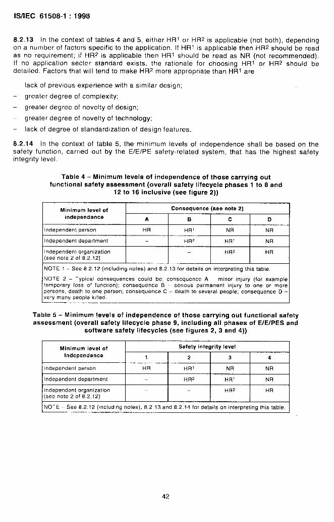
lS/lEC 61508-1:1998
8.2.13 in the context of tables 4 and 5, either HR~ or HRZ is applicable (not both), dependingon a number of factors specific to the application. If HR1 is applicable then HR2 should be readas no requirement; if HRZ is applicable then HR1 should be read as NR (not recommended).
If no application sector standard exists, the rationale for choosing HR1 or HR2 should bedetailed. Factors that will tend to make HRZ more appropriate than HR1 are
– lack of previous experience with a similar design;
– greater degree of complexity;
– greater degree of novelty of design;
– greater degree of novelty of technology;
– lack of degree of standardization of design features.
8.2.14 In the context of table 5, the minimum levels of independence shall be based on the
safety function, carried out by the E/E/PFE safety-related system, that has the highest safetyintegrity level.
Table 4 – Minimum levels of independence of those carrying outfunctional safety assessment (overall safety Iifecycle phases 1 to 8 and
12 to 16 inclusive (see figure 2))
Minimum level of Consequence (see note 2)
independence A B c D
Independent person HR HR1 NR NR
Independent department HR2 HR1 NR
Independent organization — — HR2 HR(see note 2 of 8,2,12)
NOTE 1 – See 82.12 (including notes) and 8.2.13 for details on interpreting this table.
NOTE 2 – ‘Typical consequences could be: consequence A – minor injury (for exampletemporary loss of function); consequence B - serious permanent injury to one or morepersons, death to one person; consequence C – death to several people; consequence D –very many people ki!leo.
Table 5 – Minimum levels of independence of those carrying out functional safetyassessment (overall safety Iifecycle phase 9, including all phases of E/E/PES and
software safety Iifecycles (see figures 2, 3 and 4))
Minimum level of
Independence
Safety integrity level
1 2 3 I 4
Ilndependent person
Independent department
HR HR1 NR NR
— HR2 HR1 NR
Independent organization(see note 2 of 8.2.12) I — I — I HR2 I HR
I NOTE - See 8.2.12 (including notes), 8.2.13 and 8.2.14 for details on interpreting this table. I
42
lS/lEC 61508-1:1998
Annex A[informative)
Example documentation structure
A.1 General
This annex provides an example documentation structure and method fcr specifying thedocuments for structuring the information in order to meet the requirements in clause 5. Thedocumentation has to contain sufficient information necessary to effectively perform
—. each phase of the overall, E/E/PES and software safety Iifecycles;
-- the management of functional safety (clause 6);
– functional safety assessments (clause 8).
What constitutes sufficient information will be dependent iJpon a number of factors, includingthe complexity and size of the E/E/PE safety-related systems and the requirements relating tothe specific application. The necessary documentation may be specified in application specificinternational standards.
The amount of information in each document may vary from a few lines to many pages, and the
complete set of information may be divided and presented in many physical documents or onephysical document. The physical documentation structure will again depend upon the size and
complexity of the E/E/PE safety-related systems, and will take into account company
procedures and the working practices of the specific application sector.
The example documentation structure indicated in this annex has been provided to illustrateone particular way in which the information could be structured and the way the documentscould be titled. See reference [4]’ in annex C for more details.
A document is a structured amount of information intended for human perception, that may be
interchanged as a unit between users and/or systems (see ISO 8613-1) [5]’. The term applies?herefore not only to documents in the traditional sense, but also to concepts such as data filesand database information.
In this standard, the term document is understood normally to mean information rather thanphysical documents, unless this is explicitly declared or understood in the context of the clauseor subclause in which it is stated. Documents may be available in different forms for humanpresentation (for example on paper, film or any data medium to be presented on screens ordisplays).
The example documentation structure in this annex specifies documents in two parts:
– document kind;
– activity or object.
————————
“ Figures in square brackets refer to the bibliography given in annex C.
43

IWEC 61508-1:1998
‘ he document kind is defined in the iEC 61355 [3] and characterizes the content of the.
:~~ctimerlt, for example function description or circ Ljlt diagram. The activity or object describes?.’e scope of the content, for example pump control systelm.
~ ‘e basic document kinds specified in this annex are
spec~fication – specifies, a required function, performance or activity (for examplereqtilernents specification);
description – specifies a planned or actual function, design, performance or activity (forexample function description);
instruction – specifies in detail the instructions as to when i~t-)d how to perform certain jobs(for example operator instruction);
plan – specifies the plan as to when, how and by whom specific~erforrned (for example maintenance plan);
dtagrarm – specifies the function by means of a diagram (symbols ands gr-:l:s between the symbols;
activities shall be
lines) representing
iist --- provides information in a list form (for example code list, signal list);
log -- provides information on events in a chronological log fc]rm;
report – describes the results of activities such as investigations, assessments, tests etc.(for example test report);
request – provides a description of requested actions
specified (for example maintenance request).
“~tie basic document kind may have a prefix, such as
specification, which further characterizes the content.
A.2 Safety Iifecycle document structure
that have to be approved and further
requirements specification or test
‘Tables A.1, A.2 and A.3 provide an example documentation structure for structuring theInformation in order to meet the requirements specified in clause 5. The tables indicate thesafety Iifecycle phase that is mainly associated with the documents (usually the phase in whichthey are developed). The names given to the documents in the tables is in accordance with thescheme outlined in A.1,
!n addition to the documents listed in tables A.1, A.2 and A.3, there may be supplementarydcxuments giving detailed additional information or information structured for a specificpurpose, for example parts lists, signal lists, cable lists, wiring tables, loop diagrams, list ofvariables.
NOTE – Examples of such variables are values for regulators, alarm values for variables, priorities in the executionof tasks ,n the ~Onlputer some of the values of the variables could be given before the delivery of the SYSteM,others could be given during commissioning or maintenance.
44

WIEC 61508-1:1998
Table A.1 – Example documentation structure for information related tothe overall safety Iifecycle
.—.——., Overall safety Iifecycle phase I information
conce L)t I Descr(ution (overall conce~t) I—...—.— —Overall scope definition Description (overall scope definition)
.—-—..———— —. —h:izarc ar~d ns~ analysis Descrlftlon (hazard and risk analysis)
OIerail safety requirements Speclfiwatton (overall safety requirements, comprising: overallsafety lunct[ons and overall safety integrity)
~SaJet V re~ulrements allocation I DescrlItlon (safetv requirements allocation) I
@erall o peratlon and maintenance planning Plan (overall operation arid maintenance)—.—
~Overail safety validation planning Plan (werall safet} validation)y—. .—— —.—~Overall Installation and commissioning Plan (overall lnstalation),\plann!ng Plan (overall commlssloning)
~R~allsatlon Realisatlon of Eh7PE safety-related Systems (see IEC 61508-2
I and IEC 61508-3) I
~Overall installation and commissioning Report (overall Installation);
I Report (overall commissioning)
!Overall safetv validation
Overall operation and maintenance
Overall modification and retrofit
I
Decommlssionlng or disposal
IConcerning all phase:
I
Report (overall safety validation)
Log (overall operation and maintenance)
Request (overall modification);Report (overall modification and retrofit impact analysis);Loa (overall modification and retrofit)
Report (overall decommissionir?g or disposa! impact analysis);Plan (overall decommissioning or disposal);Loa (overall decommissioning or disposal)
Plan (safety);Plan (verification);Report (verification);
IPlan (functional safety assessment);
~Report (functional safety assessment)
45

!’WEC 61508-1:1998
Table A.2 – Example docurnentatic!n structure for information related tothe E/E/l~ES safety Iifecyc!e
.. —._ — — ,—-——.-———__E/EIPES safety Iifecycle phase
—~Information
.— .——-— .—-FfE/pES safety requirements ;Spe:ificatlon (E/E/PES safety requirements: comprising:
~E:E/F>ES safety functions and E/E/PES safety Integrity).—_______ — —— ~——--.–...–______E/!=/FES validation planning ~Plan (E/L/PES safety validation)..—— —. .—._., —---—E/ E/PES clesign and development I
L’fI!YPE ‘j architecture ~Des:. rlptlon (E7E/PES architecture design, comprising:‘harcwara architecture and software architecture);Speslflcation (programmable electronic integration tests);
\Speclf!cation (integration tests of programmable electronicland non programmable electronic hardware)
harcfware architecture Descnptior (hardware architecture design),Spe:if!cation (hardware architecture integration tests)
\+a:dware module design Spe:lflcahon (hardware modules design);\Spe:if~ati~ns (hardware modules test)
Cempofwnt construction and/or procurement Hardware modules;Report (hardware modules test)
.——-.
‘~~~tableA.3)Ptogrammabie electronic !ntegrahon Repart (programmable electronic and software integration
.—-—-—
r
—.EIE/PE$ integration Report (programmable electronic and other hardware
Integration test)——- .
E/}~/PEfs ~p~r~?lon and maintenance procedures ,Instructlon (user),
-l------–--–—Instruction (operation and maintenance)
.—_. -—_—— ———~:,,;:/t>~:,:,“ ‘-(’ safety vaiidatic, n ~Rep~rt (E/E/PES safety validation)
———--——. .—.-—-—-. .—— —TE./i: /PLf; n!odcflc:ihon ~lr!struct,~r} (E213PES modification procedures);
;F?eques; (E/Ei PES modification);\Report [E/E/PES modification impact analysis);
-_————-~Log (E/E/t3ES modification)
. ..— — ..—. .—.-. .. —-—Concerning all phases \ Plar (E/ E/L3ES s;ifety);
~Plar (E/E/PES verification);I Report (E/ E/PES verification);~Plar (E; E/PES functional safety assessment);[Report (E/E/PES functional safety assessment)
— L_— -——
46

WIEC 61508-1:1998
Tab!e A.3 - Example dcwurnentatiem structure for information related tothe software safety lifecycle
~
-t
Software safety Iifecycie phase Information
Software safety requirements Specification (sottware safety requirements, comprising:software s.zfet}, functions and software safety integrity)
F- ~“””
‘$ofiware validation planning Plan (software safety validation)
~So:tware design ar~cf development
i Software architecture1’
IX,scr:ptiwr (software architecture design) (see table A.2 forhardware architecture design description);Speclficatiorl (software arch~tecturr? integration tests);Specification (prograrnrr?able electronic and softwaieinlegrauon tests);Irrstruc:ion (development tools and coding manual)
Software system design Description (software system design);Spalfication (software system integration tests)
Software module design Specification (software module design);Specification (sottware module tests)
Coding List (source code);Report (software module test);Repc)rt (code rewew)
Software module testing Report (software module test)
Sottware integration Report (software module integration test);
L
Report (software system integration test);Report (software architecture integration test)
—— ——I Pr~grammable electronic integration Report (programmable electronic and software integration test)
—\SoHware operation and maintenance InstructIon (user);~ocedures
.—IInstructon (operation and maintenance)
~Software safetv validation I Report (software safety validation)
~Sottware modification Instruction (software modification procedures);
I
Request (software modification);Report (software modification impact analysis);
I__________ ~1..og(software modification)
Concemirg all phases ‘ Plan (software safety);Plan (software verification);Report (software verification);Plan (software functional safety assessment);Report (software functional safety assessment)
.——— .——.
A.3 Physical document structure
The physical structure of the documentation is the way that the different documents are
corn b(ned into documents, document sets, binders and groups of binders. Figure A.1 showsexamples of such sets of binders structured according to user groups. The same documentmay occur in different sets.
For a large and complex system, the many physical documents are likely to be split into severalbinders. For a small, low complexity system with a limited number of physical documents, theymay be combined into one binder with different tabs for the different sets of documents (seefigure A.2).
The physical structure provides a means of selecting the documentation needed for the specificactivities by the person or group of persons performing the activities. Consequently, some ofthe physmal documents may occur in several binder sets or other media (for example computerdisks).
47

8
KMEC 61508-1:1998
NOTE -- The Information required by the documents In tab!e A 1may be contained within the dtfferent sets of
documents shown In figures A.1 and A.2. For example, within the engineering set, documenls such as the hazardand r’sk analysis descrlpt!on and/or overall safety requirements specification would be contained in It.
. . . . . . . . . . . . . . . .. .. . . . . . . . . . . . . . .. . . . . . .. .. . . . . . . . . . . . . . . . . . . . . . . . . . . . . . . . . . .. . . . . . . . . . . . . . . . .. . . .. . . . . . . . . . . . . . . .. . . . . . . . . ........ ..”.............., ~
P
#ti*l:
‘-”:B ‘ - ~‘- ‘ r ‘i
t“ ~W4Xui$l %Wa Software safety 1
: V7 ~erequirements ;
PES safety specification ;
$Overall safety
requirements, Overell safety specification
:
: L-... validation Hazard end risk requirements;
: report managementdescription
specification :
% :~
Complete set of documents:.................................................................................................................................e"..""""""""."""""".:
*
Figure A.1 – Structuring information into document sets for user groups
e---. --------- . -----------------------------------
\ Small low complexity;:::
system
Figure A.2 - Structuring information for large complex systems andsmall low complexity systems
48

lS/lEC 61508-1:1998
A.4 List of documents
The list of documents will typically include the following information:
– drawing or document number;
revision index;
– document designation code;
– title;
– date of revision;
– data carrier.
This list may appear in different forms, for example in a database capable of being sortedaccording to drawing, document number or document designation code. The documentdesignation code may contain the reference designation for the function, location or productdescribed in the document, making it a powerful tool in searching for information.
49

K5REC 61508-1:199$
Annex B(informative)
Competence of persons
E3.1 Objective
This annex outlines considerations for ensuring that persons who have responsibilities for anyoverall, E/E/PES or software safety Iifecycle activity are competent to discharge thoseresponsibilities.
$3.2 General considerations
All persons involved in any overall, HE/PES or software safety Iifecycle activity, including
management activities, should have the appropriate training, technical knowledge, experienceand qualifications relevant to the specific duties they have to perform.
Tke tratrting, experience and qualifications of all persons involved in any overall, E/E/PES orsoftware safety Iifecycle activity, including any management of functional safety activities,should bo assessed in relation to the particular application.
The following factors should be considered when assessing the competence of persons tocarry out their duties:
engineering knowledge appropriate to the application area;
engineering knowledge appropriate to the technology (for example electrical, electronic,programmable electronic, software engineering);
safety engineering knowledge appropriate to the technology;
knowledge of the legal and safety regulatory framework;
the consequences in the event of failure of the E/E/PE safety-related systems; the greaterthe consequences, the more rigorous should be the specification and assessment ofcornpbtence;
the safety integrity levels of the E/E/PE safety-related systems; the higher the safetyintegrity levels, the more rigorous should be the specification and assessment ofcompetence;
the novelty of the design, design procedures or application; the newer or more untried thedesigns, design procedures or application, the more rigorous the specification andassessment of competence should be;
previous experience and its relevance to the specific duties to be performed and thetechnology being employed; the greater the required competence levels, the closer the fdshould be between the competencies developed from previous experience and thoserequired for the specific duties to be undertaken;
relevance of qualifications to specific duties to be performed.
The training, experience and qualificatior,s of all persons involved in any overall, E/E/PES orsoftware safety Iifecycle activity should be documented.
.
.

. .—. —.——________ . ,. . ...... ..... .—.——
lS/lEC 61508-1:1998
Annex C(informative)
Bibliography
[1]
[2]
[3]
[4]
[5]
[6]
[7]
[8]
[9]
[10]
IEC 60300-3-1:1991, Dependability management – Part 3: Application guide – Section 1:Analysis techniques for dependability: Guide on methodology
IEC 60300-3-9:1995, Dependability management – Part 3: Application guide – Section 9:Risk analysis of technological systems
IEC 61355:1997, Classification and designation of documentations for p/ants, systemsand equipment
IEC 61506:1997, /ndustria/-process measurement and contro/ – Documentation ofapplication soft ware
ISO 8613-1:1994, Information technology – Open Document Architecture (ODA) andinterchange format: Introduction and general principles
ISO 10007:1995, Quality management – Guidelines for configuration management
lSO/l EC TR 15846, /formation technology – Software life cycle processes –Configuration management for software
ANSM SA S84: 1996, Application of safety Instrumented Systems for the Process/ndustries
Procedures for treating common cause failures in safety and reliability studies –Procedura/ framework and examp/es, NUREG/CR-4780, Volume 1, January 1988
Procedures for treating common cause failures in safety and reliability studies –Ana/ytica/ background and techniques, NUREG/CR-4780, Volume 2, January 1989
51

——- .—.———.
Bureau of Indian Standards
BIS is a statutory institution established under the Bureau of /ndian Standards Act, 1986 to promoteharmonious development of the activities of standardization, marking and quality certification of goodsand attending to connected matters in the country.
Copyright
BIS has the copyright of all its publications. No parl of these publications may be reproduced in anyform without the prior permission in writing of BIS. This does not preclude the free use, in course ofimplementing the standard, of necessary details, such as symbols and sizes, type or gradedesignations. Enquiries relating to copyright be addressed to the Director (Publications), 61S.
Review of Indian Standards
Amendments are issued to standards as the need arises on the basis of comments. Standards arealso reviewed periodically; a standard along with amendments is reaffirmed when such reviewindicates that no changes are needed; if the review indicates that changes are needed, it is taken upfor revision. Users of Indian Standards should ascertain that they are in possession of the latestamendments or edition by referring to the latest issue of ‘BIS Catalogue’ and ‘Standards: MonthlyAdditions’.
This Indian Standard has been developed from Dot: No. ETD 18 (5679).
Amendments Issued Since Publication
Amendment No. Date of Issue Text Affected
BUREAU OF INDIAN STANDARDSHeadquarters:
Manak Bhavan, 9 Bahadur Shah Zafar Marg, New Delhi 110002Telephones: 23230131,23233375,2323 9402 Website: www.bis.org.in
Regional Offices: Telephones
Central :
Eastern :
Manak Bhavan, 9 Bahadur Shah Zafar Marg
{23237617
NEW DELHI 110002 23233841
1/14, C.I.T. Scheme Vll M, V.I.P. Road, Kankurgachi
{
23378499,23378561KOLKATA 700054 23378626,23379120
Northern : SCO 335-336, Sector 34-A, CHANDIGARH 160022
{
2603843
2609285
Southern : C.I.T. Campus, IV Cross Road, CHENNAI 600113 ‘
{
22541216, 22541442
22542519, 22542315
Western : Manakalaya, E9 MlDC, Marol, Andheri (East)
{
28329295,28327858MUMBAI 400093 28327891,28327892
Branches: AHMEDABAD. BANGALORE. BHOPAL. BHUBANESHWAR. COIMBATORE. FARIDABAD.
GHAZIABAD. GUWAHATI. HYDERABAD. JAIPUR. KANPUR. LUCKNOW. NAGPUR.PARWANOO. PATNA. PUNE. RAJKOT. THIRUVANANTHAPURAM. VISAKHAPATNAM.
Printed by the Manager. Govt. of India Press, Farida~