ELECTROMAGNETIC COMPATIBILITY ( EMC )intra.itiltd-india.com/quality/BISStandards/E700_4_2.pdf ·...
37
IS 14700 ( Part 4/Set 2 ) : 1999 IEC 1000-4-2 ( 1995 ) Indian Standard ELECTROMAGNETIC COMPATIBILITY ( EMC ) PART 4 TESTING AND MEASUREMENTTECHNIQUES Section 2 Electrostatic Discharge Immunity Test IQ 33.100 0 BIS 1999 BUREAU OF INDIAN STANDARDS MANAK BHAVAN, 9 BAHADUR SHAH ZAFAR MARG NEW DELHI 110002 September 1999 Price Group 11
-
Upload
truongphuc -
Category
Documents
-
view
216 -
download
1
Transcript of ELECTROMAGNETIC COMPATIBILITY ( EMC )intra.itiltd-india.com/quality/BISStandards/E700_4_2.pdf ·...
IS 14700 ( Part 4/Set 2 ) : 1999 IEC 1000-4-2 ( 1995 )
Indian Standard
ELECTROMAGNETIC COMPATIBILITY ( EMC ) PART 4 TESTING AND MEASUREMENTTECHNIQUES
Section 2 Electrostatic Discharge Immunity Test
IQ 33.100
0 BIS 1999
BUREAU OF INDIAN STANDARDS MANAK BHAVAN, 9 BAHADUR SHAH ZAFAR MARG
NEW DELHI 110002
September 1999 Price Group 11

Electromagnetic Compatibility Sectional Committee, LTD 22
NATIONAL FOREWORD
This Indian Standard ( Part WSec 2 ) which is identical with IEC 1000-4-2 ( 1995 ) ‘Electromagnetic compatibility ( EMC ) - Part 4 : Testing and measurement techniques - Section 2 : Electrostatic discharge immunity test’ [ along with Amendment No.1 (1998) 1, issued by the International Electrotechnical Commission ( IEC ) was adopted by the Bureau of Indian Standards on the recommendation of the Electromagnetic Compatibility Sectional Committee and approval of the Electronics and Telecommunication Division Council.
In the adopted standard, certain conventions are not identical to those used in Indian Standards. Attention is particularly drawn to the following:
a) Wherever the words‘lnternational Standard appear referring to this standard, they shouM be read as ‘Indian Standard’.
b) Comma ( , ) has been used as a decimal marker while in Indian Standards, the current practice is to use a point ( . ) as the decimal marker.
Amendment No. 1(1998) to the above International Standard has been printed at the end.
CROSS REFERENCES
In the adopted standard, reference appears to certain International Standards for which Indian Standards also exist.The corresponding Indian Standards which are to be substituted in their place are listed below along with their degree of equivalence for the editions indicated:
international Standard Corresponding Indian Standard Equivalence
Degree of
IEC 50 ( 161 ) : 1990 International IS 1885 ( Part 64/Set 1 & 2 ) : 1987 Electro- Technically ElectrotechnicalVocabulary (IEV) technical vocabulary : Part 64 Electromagnetic Equivalent - Chapter 161 : Electromagnetic compatibility, Section 1 General terms, compatibility Section 2 Specific terms
IEC 68 - 1 : 1988 Environmental IS 9000 ( Part 1 ) : 1988 Basic environmental do testing - Part 1 : General and testing procedure for electronic and electrical guidance items: Part 1 General ( first revision)
Only the English language text of the International Standard has been retained while adopting it in this Indian Standard except the figures,

IS 14700 ( Part 4/Set 2 ) : 1999 IEC 1000-4-2 (1995)
CONTENTS
Page
Clause
Scope ...............................................................................................................................
Normative references .....................................................................................................
General ............................................................................................................................
Definitions ........................................................................................................................
Test levels .......................................................................................................................
Test generator .................................................................................................................
6.1 Characteristics ar.c! performance of the ESD generator ................................
6.2 Verification of the characteristics of the ESD generator.. ..............................
Test set-up ......................................................................................................................
7.1 Test set-up for tests performed in laboratories ...............................................
7.2 Test set-up for post-installation tests ...............................................................
Test procedure ................................................................................................................
8.1 Laboratory reference conditions .......................................................................
8.2 EUT exercising ....................................................................................................
8.3 Execution of the test .................................................................... ..- ...................
Test results and test report ...........................................................................................
Figures
1 Simplified diagram of the ESD generator . . . . . . . . . . . . . . . . . . . . . . . . . . . . . . . . . . . . . . . . . . . . . . . . . . . . . . . . . . . . . . . . .
2 Example of arrangement for verification of ESD generator performance . . . . . . . . . . . . .
3 Typical waveform of the output current of the ESD generator.. ............................. 17
4 Discharge electrodes of the ESD generator ............................................................. 18
5 Example of test set-up for table-top equipment, laboratory tests .......................... 19
6 Example of test set-up for floor-standing equipment, laboratory tests ................. 20
7 Example of test set-up for floor-standing equipment, post-installation tests ....... 21
Annexes
A Explanatory notes ........................................................................................................ 22
B Constructional details .................................................................................................. 27
4
5
6
7
8
8
9
10
11
11
11
12
14
15 16
1

As in the Original Standard, this Page is Intentionally Left Blank
IS 14700 ( Part 4/Set 2 ) : 1999 IEC 1000-4-2 (1995)
Indian Standard
ELECTROMAGNETIC COMPATIBILITY ( EMC ) PART 4 TESTING AND MEASUREMENTTECHNIQUES
Section 2 Electrostatic Discharge Immunity Test
1 Scope
This International Standard relates to the immunity requirements and test methods for electrical and electronic equipment subjected to statid electricity discharges, from operators directly, and to adjacent objects. It additionally defines ranges of test levels which relate to different environmental and installation conditions and establishes test procedures.
The object of this standard is to establish a common and reproducible basis for evaluating the performance of electrical and electronic equipment when subjected to electrostatic discharges. In addition, it includes electrostatic discharges which may occur from per- sonnel to objects near vital equipment.
This standard defines:
- typical waveform of the discharge current;
- range of test levels;
- test equipment;
- test set-up;
- test procedure.
This standard gives specifications for test performed in “laboratories” and “post- installation tests” performed on equipment in the final installation.
This standard does not intend to specify the tests to be applied to particular apparatus or systems. Its main aim is to give a general basic reference to all concerned product commit- tees of the IEC. The product committees (or users and manufacturers of equipment) remain responsible for the appropriate choice of the tests and the severity level to be applied to their equipment.
In order not to impede the task of coordination and standardization, the product commit- tees or users and manufacturers are strongly recommended to consider (in their future work or revision of old standards) the adoption of the relevant immunity tests specified in this standard.
2 Normative references
The following normative documents contain provisions which, through reference in this text, constitute provisions of this section of IEC 1000-4. At the time of publication, the editions indicated were valid. All normative documents are subject to revision, and parties
3

IS 14700 (Part4/Sec2):1999 IEC 1000-4-2 (1995)
to agreements based on this section of IEC 1000-4 are encouraged to investigate the possibility of applying the most recent editions of the normative documents indicated below. Members of IEC and IS0 maintain registers of currently valid International Standards.
IEC 50(161): 1990, international Nectrotechnical Vocabulary (IEV) - Chapter 167: Electromagnetic compatibility
IEC 68-l: 1988, Environmental testing - Part 1: General and guidance
3 General
This standard relates to equipment, systems, sub-systems and peripherals which may be involved in static electricity discharges owing to environmental and installation conditions, such as low relative humidity, use of low-conductivity (artificial-fibre) carpets, vinyl garments, etc., which may exist in allocations classified in standards relevant to electrical and electronic equipment (for more detailed information, see clause A.1 of annex A).
The tests described in this standard are considered to be a first step in the direction of commonly used tests for the qualitative evaluation of the performance of all electrical and electronic equipment as referred to in clause 1.
NOTE - From the technical point of view the precise term for the phenomenon would be ‘static electricity discharge’. However, the term ‘electrostatic discharge’ (ESD) is widely used in the technical world and in technical literature. Therefore, it has been decided to retain the term ESD in the title of this standard.
4 Definitions
For the purpose of this section of IEC 1000-4, the following definitions and terms apply and are applicable to the restricted field of electrostatic discharge; not all of them are included in IEC 50(161) [IEV].
4.1 degradatlon (of performance): An undesired departure in the operational perform- ance of any device, equipment or system from its intended performance. [IEV 161-01-19)
NOTE - The term ‘degradation’ can apply to temporary or permanent failure.
4.2 electromagnetic compatlbllity (EM): The ability of an equipment or system to function satisfactorily in its electromagnetic environment without introducing intolerable electromagnetic disturbances to anything in that environment. [IEV 161-01-071
4.3 antlstatlc materlal: Material exhibiting properties which minimize charge genera- tion when rubbed against or separated from the same or other similar materials.
4.4 energy storage capacitor: The capacitor of the ESD-generator representing the capacity of a human body charged to the test voltage value. This may be provided as a discrete component, or a distributed capacitance.

IS 14700 ( Part 4/Set 2) : 1999 IEC 1000-4-2 (1995)
4.5 ESD: Electrostatic discharge (see 4.10).
4.6 EUT: Equipment under test.
4.7 ground reference plane (GRP): A flat conductive surface whose potential is used as a common reference. [IEV 161-04-361
4.8 coupling plane: A metal sheet or plate, to which discharges are applied to simulate electrostatic discharge to objects adjacent to the EUT. HCP: Horizontal Coupling Plane; VCP: Vertical Coupling Plane.
4.9 holding time: Interval of time within which the decrease of the test voltage due to leakage, prior to the discharge, is not greater than 10 %.
4.10 electrostatic discharge; ESD: A transfer of electric charge between bodies of different electrostatic potential in proximity or through direct contact. [IEV 161-01-221
4.11 immunity (to a disturbance): The ability of a device, equipment or system to perform without degradation in the presence of an electromagnetic disturbance. (IEV 161- 01 -201
4.12 contact discharge method: A method of testing, in which the electrode of the test generator is held in contact with the EUT, and the discharge actuated by the discharge switch within the generator.
4.13 air discharge method: A method of testing, in which the charged electrode of the test generator is brought close to the EUT, and the discharge actuated by a spark to the EUT.
4.14 direct application: Application of the discharge directly to the EUT.
4.15 indirect application: Application of the discharge to a coupling plane in the vicinity of the EUT, and simulation of personnel discharge the EUT.
to objects which are adjacent to
5 Test levels
The preferential range of test levels for the ESD test is given in table 1.
Testing shall also be satisfied at the lower levels given in table 1.
Details concerning the various parameters which may influence the voltage level to which the human body may be charged are given in clause A.2 of annex A. Clause A.4 also contains examples of the application of the test levels related to environmental (instal- lation) classes.
5

IS 14700 ( Part 4lSec 2) : 1999 IEC 1000-4-2 (1995)
Contact discharge is the preferred test method. Air discharges shall be used where contact discharge cannot be applied. Voltages for each test method are given in tables la and 1 b. The voltages shown are different for each method due to the differing methods Of
test. It is not intended to imply that the test severity is equivalent between test methods.
Further information is given in clauses A.3, A.4 and A.5 of annex A.
Table 1 - Test levels
la - Contact discharge lb-Airdischarge
Lsvel Test voltage Level Test voltage kV kV
1 2 1 2 2 4 2 4 3 6 3 8 4 a x ” & x ‘1 SpEial
1) .x’ is an open level. The level has to be specified in the dedicated equipment specification. If higher voltages than those shown are specified, special test equipment may be needed.
6 Test generator
The test generator consists, in its main parts, of:
charging resistor Rc;
energy-storage capacitor Cs;
distributed capacitance Cd;
discharge resistor Rd;
voltage indicator;
discharge switch;
interchangeable tips of the discharge electrode (see figure 4);
discharge return cable;
power supply unit.
A simplified diagram of the ESD generator is given in figure 1. Constructional details are not given.
The generator shall meet the requirements given in 6.1 and 6.2.
6

1s 14700 ( Part 4/Set 2 IEC 1000-4-2 ) : 1999 (1995)
6.1 Characteristics and performance of the ESD generator
Specifications
- energy storage capacitance (C, + Cd):
- discharge resistance (RJ:
- charging resistance (R,):
- output voltage (see note 1):
- tolerance of the output voltage indication:
- polarity of the output voltage:
- holding time:
- discharge, mode of operation (see note 2):
- waveshape of the discharge current:
NOTES
150 pF f 10 %;
330n*lo%;
between 50 MR and 100 Ma;
up to 8 kV (nominal) for contact discharge; up to 15 kV (nominal) for air discharge:
*5 %;
positive and negative (switchable);
at least 5 s;
single discharge (time between successive discharges at least 1 s);
see 6.2.
1 Open circuit voltage measured at the energy storage capacitor.
2 The generator should be able to generate at a repetition rate of at least 20 discharges per second for exploratory purposes only.
The generator shall be provided with means of preventing unintended radiated or conducted emissions, either of pulse or continuous type, so as not to disturb the EUT or auxiliary test equipment by parasitic effects.
The energy storage capacitor, the discharge resistor, and the discharge switch shall be placed as close as possible to the discharge electrode.
The dimensions of the discharge tips are given in figure 4.
For the air discharge test method the same generator is used and the discharge switch has to be closed. The generator shall be fitted with the round tip shown in figure 4.
The discharge return cable of the test generator shall be in general 2 m long, and constructed to allow the generator to meet the waveform specification. It shall be suffi- ciently insulated to prevent the flow of the discharge current to personnel or conducting surfaces other than via its termination, during the ESD test.
In cases where a 2 m length of the discharge return cable is insufficient, (e.g. for tall EUTs), a length not exceeding 3 m may be used, but compliance with the waveform speci- fication shall be verified.

IS 14700 ( Part 4/Set 2 ) : 1999 IEC 1000-4-2 (1995)
6.2 Verification of fhe characterisiics of ihe ESD generator
In order to compare the test results obtained from different test generators, the character- istics shown in table 2 shall be verified using the discharge return cable to be used in the testing.
Table 2 - Waveform parameters
Led
1
2
3 4
Rise time { Current
with discharge (f30 %) switch at 30 ns
ns A
h78llt
(*30 %)
at 60 ns
A
2 7.5 0,7 to 1 4 2
4 15 0.7kI 1 8 4
6 22.6 0,7 to 1 12 6
8 30 0,7 to 1 16 8
The waveform of the output current of the ESD generator during the verification procedure shall conform to figure 3.
The values of the characteristics of the discharge current shall be verified with 1 000 MHz bandwidth measuring instrumentation.
A lower bandwidth implies limitations in the measurement of rise time and amplitude of the first current peak.
For verification, the tip of the discharge electrode shall be placed in direct contact with the current-sensing transducer,. and the generator operated in the contact discharge mode.
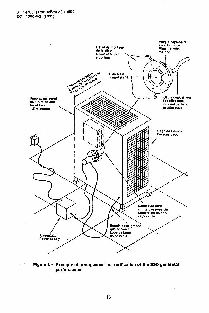
The typical arrangement for the verification of the ES0 generator performance is given in figure 2. The bandwidth of the target has to be more than 1 GHz. Constructional details of a possible design for the current-sensing transducer are given in annex 6.
Other arrangements that imply the use of a laboratory Faraday cage having dimensions different from those in figure 2 are allowed; separation of the Faraday cage from the target plane is also allowed, but in both cases the distance between the sensOr and the ground- ing terminal point of the ES0 ‘generator shall be respected (1 m), as well as the layout of the discharge return cable.
The ES0 generator shall be re-calibrated in defined time periods in accordance with a recognized quality assurance system.
7 Test set-up
The test set-up consists of the test generator, EUT and auxiliary instrumentation neces- sary to perform direct and indirect application of discharges to the EUT in the following manner:
8

IS 14700 ( Part 4/Set 2 ) : 1999 IEC 1000-4-2 (1995)
a) contact discharge to the conductive surfaces and to coupling planes;
b) air discharge at insulating surfaces.
Two different types of tests can be distinguished:
- type (conformance) tests performed in laboratories;
- post installation tests performed on equipment in its final installed conditions.
The preferred test method is that of type tests performed in laboratories.
The EUT shall be arranged in accordance with the manufacturer’s instructions for instal- lation (if any).
7.1 Test set-up for tests performed in laboratories
The following requirements apply to tests performed in laboratories under environmental reference conditions outlined in 8.1.
A ground reference plane shall be provided on the floor of the laboratory. It shall be a metallic sheet (copper or aluminium) of 0.25 mm minimum thickness; other metallic materials’may be used but they shall have at least 0.85 mm minimum thickness.
The minimum size of the reference plane is 1 m2, the exact size depending on the dimen- sions of the EUT. It shall project beyond the EUT or coupling plane by at least 0,5 m on all sides, and shall be connected to the protective grounding system.
Local safety regulations shall always be met.
The EUT shall be arranged and connected according to its functional requirements.
A distance of 1 m minimum shall be provided between the equipment under test and the walls of the laboratory and any other metallic structure.
The EUT shall be connected to the grounding system, in accordance with its installation specifications. ho additional grounding connections are allowed.
The positioning of the power and signal cables shall be representative of installation practice.
The discharge return cable of the ESD generator shall be connected to the ground reference plane. The total length of this cable is in general 2 m.
In cases where this length exceeds the length necessary to apply the discharges to be selected points, the excess length shall, where possible, be placed non-inductively off the ground reference plane and shall not come closer than 0,2 m to other conductive parts in the test set-up.
9
IS 14700 ( Pat? 4/Set 2 ) : 1999 IEC 1000-4-2 (1995)
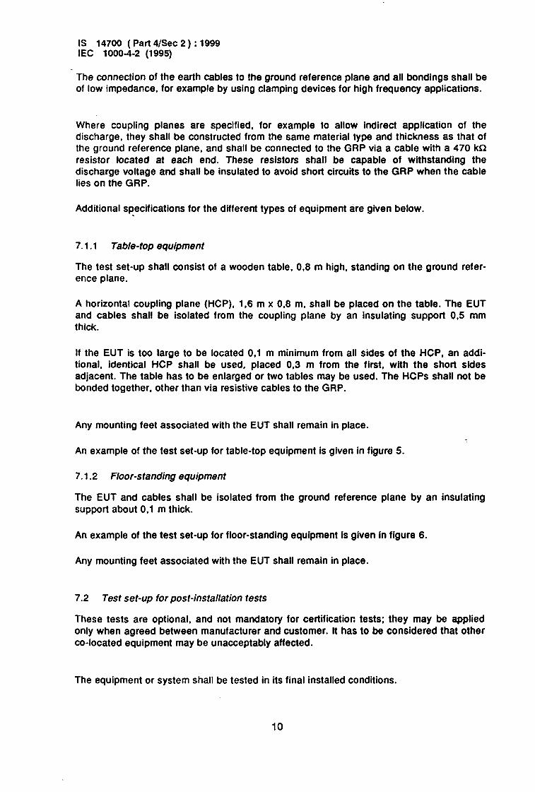
The connection of the earth cables to the ground reference plane and all bondings shall be of low impedance, for example by using clamping devices for high frequency applications.
Where coupling planes are specified, for example to allow indirect application of the discharge, they shall be constructed from the same material type and thickness as that of the ground reference plane, and shall be connected to the GRP via a cable with a 470 kR resistor located at each end. These resistors shall be capable of withstanding the discharge voltage and shall be insulated to avoid short circuits to the GRP when the cable lies on the GRP.
Additional specifications for the different types of equipment are given below. .
7.1 .l Table-top equipment
The test set-up shall consist of a wooden table, 0.8 m high, standing on the ground refer- ence plane.
A horizontal coupling plane (HCP), 1,6 m x 0.8 m, shall be placed on the table. The EUT and cables shall be isolated from the coupling plane by an insulating support 0,5 mm thick.
If the EUT is too large to be located 0.1 m minimum from all sides of the HCP, an addi- tional, identical HCP shall be used, placed 0,3 m from the first, with the short sides adjacent. The table has to be enlarged or two tables may be used. The HCPs shall not be bonded together, other than via resistive cables to the GRP.
Any mounting feet associated with the EUT shall remain in place.
An example of the test set-up for table-top equipment is given in figure 5.
7.1.2 Floor-standing equipment
The EUT and cables shall be isolated from the ground reference plane by an insulating support about 0.1 m thick.
An example of the test set-up for floor-standing equipment is given in figure 6.
Any mounting feet associated with the EUT shall remain in place.
7.2 Test Set-Up for post-installation t8StS
These tests are optional, and not mandatory for certification tests; they may be applied only when agreed between manufacturer and customer. It has to be considered that other co-located equipment may be unacceptably affected.
The equipment or system shall be tested in its final installed conditions.
10

IS 14700 ( Part 4/Set 2) : 1999 IEC 1000-4-2 (1995)
In order to facilitate a connection for the discharge return cable, a ground reference plane shall be placed on the floor of the installation, close to the EUT at about 0.1 m distance. This plane should be of copper or aluminium not less than 0,25 mm thick. Other metallic materials may be used, providing the minimum thickness is 0,65 mm. The plane should be approximately 0,3 m wide, and 2 m in length where the installation allows.
This ground reference plane should be connected to the pbtective earthing system. Where this is not possible, it should be connected to the earthing terminal of the EUT, if available.
The discharge return &able of the ESD generator shall be, connected to the reference plane at a point close to the EUT. Where the EUT is installed on a metal table, the table shall be connected to the reference plane via a cable with a 470 kiL resistor located at each end, to prevent a build-up of charge.
An example of the set-up for post-installation tests is given in figure 7.
8 Test procedure
8.1 Laboratory reference conditions
In order to minimize the imI~:ictbf environmental parameters on test results, the tests shall be carried o,ut in clknattc ‘and electromagnetic reference conditions as specified in 8.1 .I and 8.1.2. \
8.1 .l Climatic condhions
In the case of air discharge testing, the climatic conditions shall be within the following ranges:
- ambient temperature: 15 “C to 35 “C;
- relative humidity: 30 % to 60 %;
- atmospheric pressure: 86 kPa (860 mbar) to 106 kPa (1 060 mbar).
NOTE - Any other values are specified in the product specification.
The EUT shall be operated within its intended climatic conditions.
8.1.2 Electromagnetic conditions
The electromagnetic environment of the laboratory shall not influence the test results.
8.2 EUT exercising
The test programs and software shall be chosen so as to exercise all normal modes of operation of the EUT. The use of special exercising software is encouraged, but permitted only where it can be shown that the EUT is being comprehensively exercised.
For conformance testing, the EUT shall be continually operated in its most sensitive mode (program cycle) which shall be determined by preliminary testing.
1:

IS 14700 ( Part 4/Set 2 ) : 1999 IEC 1000-4-2 (1995)
If monitoring equipment is required, it should be decoupled in order to reduce the possi- bility of erroneous failure indication.
The testing shall be performed by direct and indirect application of discharges to the EUT according to a test plan. This should include:
- representative operating conditions of the EUT;
- whether the EUT should be tested as table-top or floor-standing;
- the points at which discharges are to be applied;
- at each point, whether contact or air discharges are to be applied;
- the test level to be applied;
- the number of discharges to be applied at each point for compliance testing;
- whether post-installation tests are also to be applied.
It may be necessary to carry out some investigatory testing to establish some aspects of the test plan.
8.3.1 Direct application of discharges to the EUT
The static electricity discharges shall be applied only to such points and surfaces of the EUT which are accessible to personnel during normal usage.
Inside the EUT, only the points and/or surfaces which have to be acceded to perform customer’s maintenance are included unless clear instructions for the use of electrostatic discharges precautions (e.g. use of wrist straps) are prescribed by the manufacturer (see clause A.5 of annex A).
The application of discharges to any point of the equipment which is accessible only for maintenance purposes, excluding customer’s maintenance, is not allowed unless different prescription is given in the dedicated product specification.
The test voltage shall be increased from the minimum to the selected test level, in order to determine any threshold of failure (see clause 5). The final test level should not exceed the product specification value in order to avoid damage to the equipment.
The test shall be performed with single discharges. On preselected points at least ten single discharges (in the most sensitive polarity) shall be applied.
For the time interval between successive single discharges an initial value of 1 s is recom- mended. Longer intervals may be necessary to determine whether a system failure has occurred.
NOTE - The points to which the discharges should be applied may be selected by means of an exploration carried out at a repetition-rate of 20 discharges per second, or more.
12
IS 14700 ( Part 4/Set 2 ) : 1999 IEC 1000-4-2 (1995)
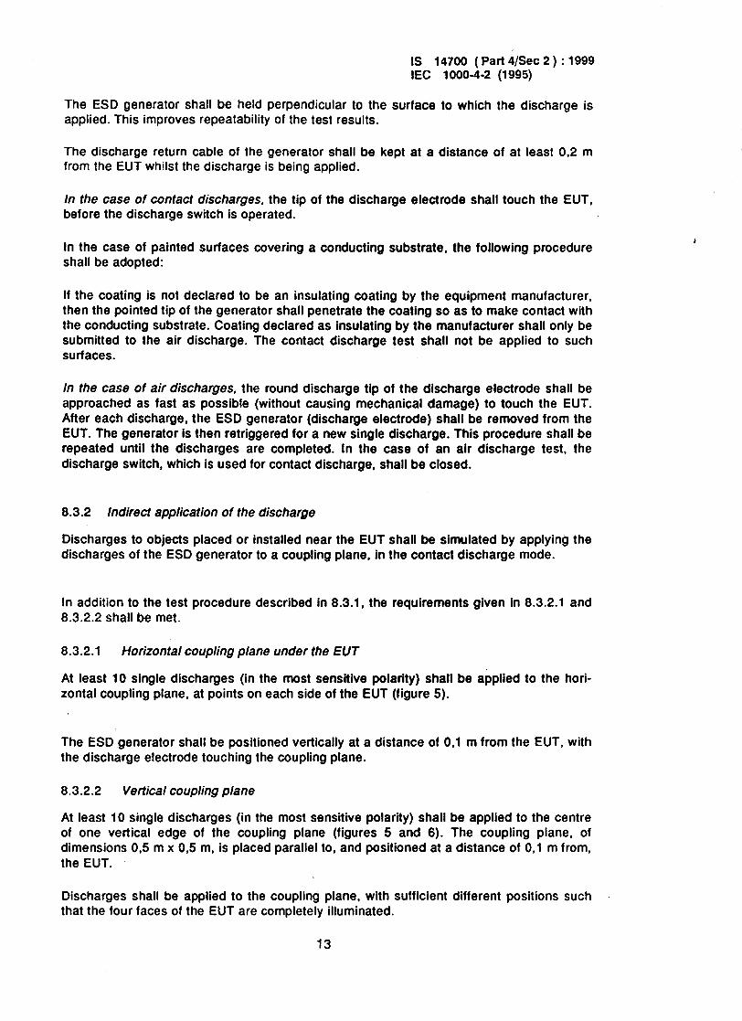
The ESD generator shall be held perpendicular to the surface to which the discharge is applied. This improves repeatability of the test results.
The discharge return cable of the generator shall be kept from the EUT whilst the discharge is being applied.
In the case of contact discharges, the tip of the discharge before the discharge switch is operated.
at a distance of at least 0.2 m
electrode shall touch the EUT,
In the case of painted surfaces covering a conducting substrate, the following procedure shall be adopted:
If the coating is not declared to be an insulating coating by the equipment manufacturer, then the pointed tip of the generator shall penetrate the coating so as to make contact with the conducting substrate. Coating declared as insulating by the manufacturer shall only be submitted to the air discharge. The contact discharge test shall not be applied to such surfaces.
In the case of air discharges, the round discharge tip of the discharge electrode shall be approached as fast as possible (without causing mechanical damage) to touch the EUT. After each discharge, the ESD generator (discharge electrode) shall be removed from the EUT. The generator is then retriggered for a new single discharge. This procedure shall be repeated until the discharges are completed. In the case of an air discharge test, the discharge switch, which is used for contact discharge, shall be closed.
63.2 Indirect application of the discharge
Discharges to objects placed or installed near the EUT shall be simulated by applying the discharges of the ESD generator to a coupling plane, in the contact discharge mode.
In addition to the test procedure described in 8.3.1, the requirements given in 8.3.2.1 and 8.3.2.2 shall be met.
8.3.2.1 Horizontal coupling plane under the EU T
At least 10 single discharges (in the most sensitive polarity) shall be applied to the hori- zontal coupling plane, at points on each side of the EUT (figure 5).
The ESD generator shall be positioned vertically at a distance of 0.1 m from the EUT, with the discharge electrode touching the coupling plane.
8.3.2.2 Vertical coupling plane
At least 10 single discharges (in the most sensitive polarity) shall be applied to the centre of one vertical edge of the coupling plane (figures 5 and 6). The coupling plane, of dimensions 0.5 m x 05 m, is placed parallel to, and positioned at a distance of 0,l m from, the EUT.
Discharges shall be applied to the coupling plane, with sufficient different positions such that the four faces of the EUT are completely illuminated.
13

IS 14700 (Part 4/Set 2) : 1999 IEC 1000-4-2 (1995)
9 Test results and test report
This clause gives a guide for the evaluation of the test results and for the test report, related to this standard.
The variety and diversity of equipment and systems to be tested make the task of establishing the effects of this test on equipment and systems difficult.
The test results shall be classified on the basis of the operating conditions and the functional specifications of the equipment under test, as in the following, unless different specifications are given by product committees or product specifications:
1) normal performance within the specification limits;
2) temporary degradation or less of function or performance which is self-recoverable;
3) temporary degradation or loss of function or performance which requires operator intervention or system reset;
4) degradation or loss of function which is not recoverable due to damage of equip- ment (components) or software, or loss of data.
Equipment shall not become dangerous or unsafe as a result of the application of the tests defined in this standard.
In the case of acceptance tests, the test program and the interpretation of the test results have to be described in the specific product standard.
As general rule, the test result is positive if the equipment shows its immunity, for all the period of application of the test. and at the end of the tests the EUT fulfils the functional requirements established in the technical specification.
The technical specification may define effects on the EUT, that may be considered insigni- ficant and therefore acceptable.
For these conditions it shall be verified that the equipment is able to recover its operative capabilities by itself at the end of the test; the time interval during which the equipment has lost its functional capabilities shall be therefore recorded. These verifications are binding for the definitive evaluation of the test result.
The test report shall include the test conditions and the test results.
14

IS 14700 ( Part 4/Set 2 ) : 1999 IEC 1000-4-2 (1995)
r’*~~~~~-.o ZZZ.%$hparge
Alimentation HT CC DC HV supply
- CB= 15OpF
Connexion de retour du courant de dbcharge
0 Discharge return connection
NOTE - Cd, omitted in the figure, is a distributed capacitance which exists between the generator and the EUT, GRP. and coupling planes. Because the capacitance is distributed over the whole of the generator, it is not possible to show this in the circuit.
,
Flgure 1 - Simplified dragram of the ESD generator
15
IS 14700 ( Part 4/Set 2 ) : 1999 IEC 1000-4-2 (1995)
Face avant: carr6 de 1,5mdec&& Front face 1,5 m square
D&ail de montage de la cible
Plaque coplanaire avec I’anneau Plate flat with
oscilloscope
Cage de Faraday Faraday cage
/
Connexion aussi courte que possible Connection as short .
Boucle aussi grande
Flgure 2 - Example of arrangement for verification of the ESD generator performance
16

I W&W I peak
I
100%.
90 %
I r, 60 ns -
10 %
- 30ns -
IS 14700 ( Part 4/Set 2 ) : 1999 IEC 1000-4-2 (1995)
--II---
r,-0,7:1 ns
Values are given in table 2.
Figure 3 - Typlcal waveform of the output current of the L%D genetatOr
17

IS 14700 ( Part 4/Set 2) : 1999 IEC 1000-4-2 (1995)
Corps du gOn6rateur
/
Body of generator
(Note)
-
Figure 4a - Air discharges
08 ’ -0.05
-
Point6 Sharp point
Figure 4b - Contact discharger
Dimensions in millimetres
NOTE - The discharge switch (e.g. vacuum relay) shall be mounted as close as possible to the tip of the discharge electrode.
Figure 4 - Discharge electrodes of the ESD generator
18

IS 14700 ( Part 4/Set 2 ) : 1999 IEC 1000-4-2 (1995)
Position typique pour application directe Typical position for direct application
Position typique pour d&charge indirecte sur le PCH Typical position for indirect discharge to HCP A\
Position typique pour &charge indirecte sur le PCV Typical position for indirect discharge to VCP
Plan& Ground
Wooden table h = 0.8 m
Flgure 5 - Example of test set-up for table-top equipment, laboratory tests
19

IS 14700 (Part 4/Set 2) : 1999 IEC 1000-4-2 (1995)
Conducteur de protection Protective conductor
Position typique pour application directe
Position typique pour dbcharge sur le PCV Typical position for discharge to VCP
\ lll.I \ II / I \ / CAble d’alimer&tfon
ms,. “” .P.“.“.._
around reference plane Power supply
Figure 6 - Example of test set-up for floor standing equlpment, laboratory tests
20

IS 14700 ( Part 4/Set 2 ) : 1999 IEC 1000-4-2 (1995)
Conducteur de protection Protective conductor
2m Plan de r6f6renoe
Alimentation .Power supply
Ground reference plane
Figure 7 - Example of test set-up for floor-standing equlpment, post-installation tests
21

IS 14700 ( Part 4/Set 2 ) : 1999 IEC 1000-4-2 (1995)
Annex A (informative)
Explanatory notes
A.1 General considerations
The problem of protecting equipment against the discharge of static electricity has gained considerable importance for manufacturers and users.
The extensive use of microelectronic components has emphasized the need to define the aspects of the problem and to seek a solution in order to enhance products/system reliability.
The problem of static electricity accumulation and subsequent discharges becomes more relevant for uncontrolled environments and the widespread application of equipment and systems in a wide range of industrial plants.
Equipment may also be subjected to electromagnetic energies whenever discharges occur from personnel to nearby objects. Additionally, discharges can occur between metal objects, such as chairs and tables, in the proximity of equipment. However, based on limited experience available to date, it is considered that the tests described in this standard may adequately simulate the effects of the latter phenomenon. This aspect will be investigated and may lead to an amendment of this standard.
The effects of the operator discharge may be a simple malfunction of the equipment or damage of electronic components. The dominant effects can be attributed to the para- meters of the discharge current (rise time, duration, etc.).
The knowledge of the problem and the necessity to have a tool to assist in the prevention of undesirable effects due to the discharge of static electricity on equipment, have initiated the development of the standard testing procedure described in this standard.
A.2 Influences of the environmental condltlons on the levels of charge
The generation of electrostatic charges is especially favoured by the combination of synthetic fabrics and dry atmosphere. There are many possible variations in the charging process. A common situation is one in which an operator walks over a carpet and at each step loses or gains electrons from his body to the fabric. Friction between the operator’s clothing and his chair can also produce an exchange of charges. The operator’s body may be charged either directly or by electrostatic inductions; in the latter case a conducting carpet will give no protection unless the operator is adequately earthed to it.
The graphic representation of figure A.1 shows the voltage values to which different fabrics may be charged depending.on the relative humidity of the atmosphere.
22
IS 14700 ( Part 4/Set 2 ) : 1999 IEC 1000-4-2 (1995)
Equipment may be directly subjected to discharges of voltage values up to several kilovolts, depending on the type of synthetic fabric and the relative humidity of the environ- ment.
A.3 Relatlonshlp of envlronmental levels to alr and contact discharge
As a measurable quantity, static voltage levels found in user environments have been applied to define immunity requirements. However, it has been shown that energy transfer is a function of the discharge current rather than, as well as, of the electrostatic voltage existing prior to the discharge. Further, it has been found that the discharge current typically is less than proportional to the pre-discharge voltage in the higher level ranges.
Possible reasons for non-proportional relationship between pre-discharge voltage and discharge current are:
- The discharge of high-voltage charges typically should occur through a long arcing path which increases the rise time, hence keeping the higher spectral components of the discharge current less than proportional to the pre-discharge voltage.
- High charge voltage levels will more likely develop across a small capacttance, assuming the amount of charge should be constant for a typical charge generation event. Conversely, high charge voltages across a large capacitance would need a number of successive generation events which is less likely to occur. This means that the charge energy tends to become constant between the higher charge voltages found in the user environment.
As a conclusion from the above, the immunity requirements for a given user environment need to be defined in terms of discharge current amplitudes.
Having recognized this concept, the design of the tester is eased. Trade-off in the choice of tester charge voltage and discharge impedance can be applied to achieve desired discharge current amplitudes.
A.4 Selection of test levels
The test levels should be selected in accordance with the most realistic installation and environmental conditions; a guideline is given in table A.1.
23

IS 14700 ( Part 4/Set 2 ) : 1999 IEC 1000-4-2 (1995)
Table A.1 - Guideline for the selection of the test levels
ClaSS
1 2 3 a
Relative humfdii aslowas
36
35 10 50 10
Antistatic material
X
X
Synthetic mat&al
X
X
Maximum voltage
kV
2 4
8
15
The installation and environmental classes recommended are related to the test levels out- lined in clause 5 of this standard.
For some materials, for example wood, concrete and ceramic, the probable level is not greater than level 2.
NOTE - It is important, when considering the selection of an appropriate test level for a particular environ- ment, to understand the critical parameters of the ESD effect.
The most critical parameter is perhaps the rate of change of discharge current which may be obtained through a variety of combinations of charging voltage, peak discharge current and rise time.
For example, the required ESD stress for the 15 kV synthetic material environment is more than adequately covered by the 8 kV130 A class 4 test using the ESD generator contact discharge defined in this standard.
However, in a very dry environment with synthetic materials. higher voltages than 15 kV occur.
In the case of testing equipment with insulating surfaces, the air discharge method with voltages up to 15 kV may be used.
A.5 Selectlon of t6st polnts
The test points to be considered may, for example, include the following locations as applicable:
- points on metallic sections of a cabinet which are electrically isolated from ground;
- any point in the control or keyboard area and any other point of man-machine communication, such as switches, knobs, buttons, and other operator-accessible areas;
- indicators, LEDs, slots, grilles, connector hoods, etc.
A.6 Technical ratlonale for the use of the contact discharge method
In general the reproducibility of the previous test method (air discharge) was influenced by, for example, the speed of approach of the discharge tip, humidity, and construction of the test equipment, leading to variations in pulse rise time and magnitude of the discharge current.
In previous designs of ES0 testers, the ES0 event was simulated by discharging a charged capacitor through a discharge tip onto the EUT, the discharge tip forming a spark gap at the surface of the EUT.
24

IS 14700 ( Part 4/Set 2 ) : 1999 IEC 1000-4-2 (1995)
The spark is a very complicated physical phenomenon. It has been shown that with a moving spark gap the resulting rise time (or rising slope) of the discharge current can vary from less than 1 ns and more than 20 ns, as the approach speed is varied.
Keeping the approach speed constant does not result in constant rise time. For some voltage/speed combinations, the rise time still fluctuates by a factor of up to 30.
One proposed way to stabilize the rise time is to use a mechanically fixed spark gap. Although the rise time is stabilized with this method, it cannot be recommended because the resulting rise time is much slower than the rise time of the natural event to be simulated.
The high-frequency content of the real ESD event is not properly simulated with this method. Using various types of triggering devices (e.g. gas tubes or thyratrons) instead of the open spark, is another possibility, but such kinds of triggering devices produce rise times which are still too low compared to the rise times of the real ESD event.
The only triggering device known today which is able to produce repeatable and fast rising discharge currents is the relay. The relay should have sufficient voltage capability and a single contact (to avoid double discharges in the rising part). For higher voltages, vacuum relays prove to be useful. Experience shows that by using a relay as the triggering device, not only the measured discharge pulse shape is much more repeatable in its rising part, but also the test results with real EUTs are more reproducible.
Consequently the relay-driven impulse tester is a device that produces a specified current pulse (amplitude and rise time).
This current is related to the real ESD voltage, as described in clause A.3.
A.7 Selectlon of elements for the ESD generator
A storage capacitance shall be used which is representative of the capacitance of the human body. A nominal value of 150 pF has been determined suitable for this purpose.
A resistance of 330 R has been chosen to represent the source resistance of a human body holding a metallic object such as a key or tool. It has been shown that this metal discharge situation is sufficiently severe to represent all human discharges in the field.
25

IS 14700 ( Part 4/Set 2 ) : 1999 IEC 1000-4-2 (1995)
16
15
14
13
\
\ 1 ‘\
5 1
Figure A.1 -
\
\ 9
‘\ \
+‘.
20 90 ,‘I 40 60 60 70 60 90 100 Humidit relative
35 w Relative humidity %
exemple: pikes de bureau sans contrdle d’humiditb office rooms without humidity control (wintertime)
(en hiver)
\
\
\ SynthBtique Synthetic
\
\
\
\
\
Maximum values of electrostatic voltages to which operators may be charged while In contact with the materlals mentloned In clause A.2
26

IS 14700 ( Part 4/Set 2 ) : 1999 IEC 1000-4-2 (1995)
Annex B (informative)
Constructional details
B.1 Current-sensing transducer
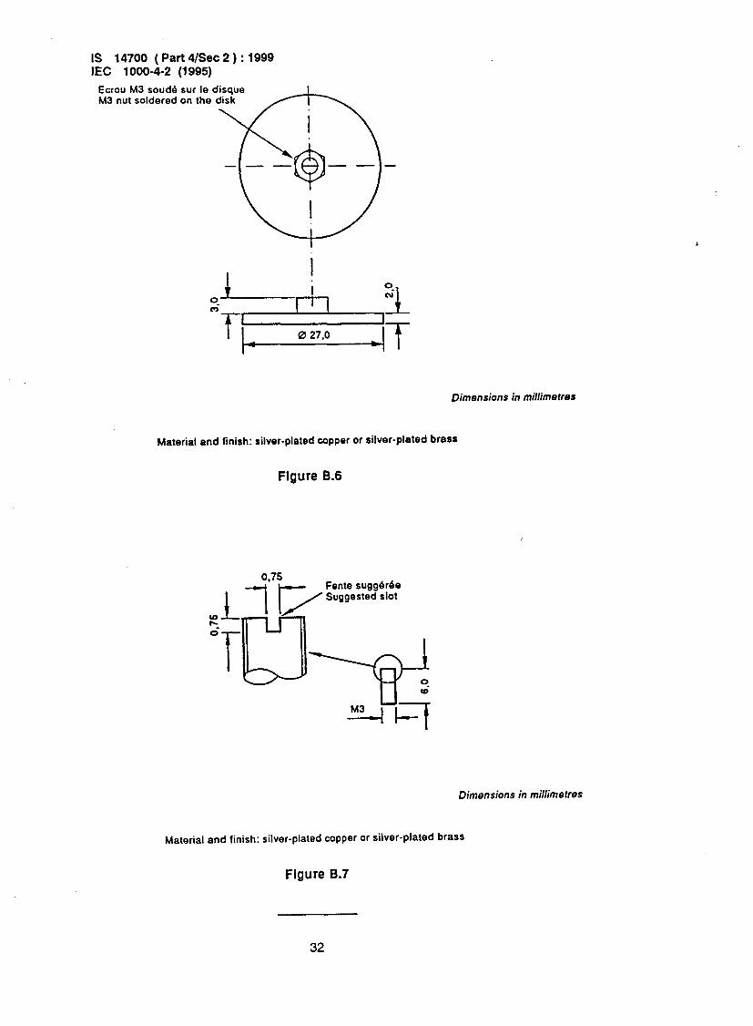
The constructional details for a possible current-sensing transducer are shown in the figures B.l to 8.7.
The following sequence of assembly should be followed:
1) Solder the 25 load resistors “7” (51 R, 5 %, 0,25 W) onto the output side disc “3” and shave the soldered terminals.
2) Solder the 5 matching resistors “8” (240 R, 5 %, 0.25 W) in a pentagonal disposition onto the output connector, of Type N coaxial construction.
3) Assemble the output side disc “3”, complete with load resistors, onto the output connector flange “1” using 4 screws M2,5 Pan Hd 8.5 mm long.
4) Assemble the output connector complete with matching resistors, “7” onto the out- put connector flange “1” using 4 screws M3.
5) Solder the input disc “4”, with the screw support for electrode “8” screwed and soldered, on both the load and matching resistors group. Shave the soldered terminals.
8) Screw the flat electrode disc “5” on the screw support for electrode “8”. then assemble the support for fixing “2” using 8 screws M3 Pan Hd 8,5 mm long.
8.2 Inductive current probe
Description and constructional details are under consideration.
27

IS 14700 ( Part 4/Set 2 ) : 1999 IEC 1000-4-2 (1995)
Coupe A-A Section A-A
Connecteur type N-fiche Connecteur type N-embase Type N connector-plug Type N connector-socket
oire de protection ou plaque frontale de la cage Wall of the shielding cabinet or front plane of the cage
i
Item atv Screws QTY
1 1 f&PANHDSCx6,5mmLG 12
2 1
3 1
4 1
5 1 M2.5 PAN HD SC x 5.0 mm LG 3
6 1
7 25 Resismf 51 n
6 5 Resismr 240 a
Wwe B-1 - Constructional details of the resistive load
28

IS 14700 ( Part 4/Set 2 ) : 1999 IEC 10004-2 (1995)
.
0 19.0
Section A-A
8 trous 0 3.2-3.4 Oquidistants sur un cercle de 0 44.0 comme indiqub 8 holes 0 3.2-3.4 equispaced
=PCD position as shown
4 trous M3 Bquidistants SW un carcle de 0 26.0 comme indiqub
I 4 holes M3 equispaced
m PC0 position as shown
3 trous M2.5 Oquidistants sur un cercle de 0 14.5 comme indiqub
Dimensions in millimetres
Material and finish: silver-plated copper or silver-plated brass
Figure 8.2
29

IS 14700 ( Part 4/Set 2) : 1999 IEC 1000-4-2 (1995)
8 trous 0 3.2-3.4 bquidistants sur un cercle de 0 80,O
8 trous M3 hquidistants sur un cercle de 0 44.0
0 80.0
I
I
I : : I
: 8 :
I
I
0 41.0
0 70.0
Dimensions in millimetres
Material and finish: silver-plated copper or silver-plated brass
Figure 8.3
30

IS 14700 ( Part s/See 2 ) : 1999 IEC 1000-4-2 (1995)
25 trous 0 1.0 Oquidistants SW un cercle de 0 24.0 comme indique 25 holes 0 1.0 equispaced
(24.oPCD position as shown
SW un cercle de 0 14.5 comme indique 3 holes 0 2.7-2.9 equispaced
1.1 14 5 PC0 position as shown
Dimensions in~millimetres
Material and finish: silver-plated copper or silver-plated brass 1 mm thick
Figure 8.4
25 trout 0 1.0 Bquidistants sur un cercle de 0 24.0 comme indique
5 trous 0 1 .O equidistants sur un cercle de 0 5.0 comme indique S holes 0 1 .O equispaced
mPCD position as shown
Dimensions in millimetres
Material and finish: silver-plated copper or silver-plated brass 1 mm thick
Figure 6.5
31
IS 14700 ( Part 4/Set 2 ) : 1999 IEC 1000-4-2 (1995)
Ecrou M3 soud6 SW le disque I M3 nut soldered on the disk
Dimensions in millimetrer
Material and finish: silver-plated copper or silver-plated brass
Figure 8.6
Fente tuggerbe
Dimensions in millimetres
Material and finish: silver-plated copper or silver-plated brass
Figure 8.7
32

IS 14700 ( Part 4/Set 2 ) : 1999 IEC 1000-4-2 (1995)
AMENDMENT NO. 1
Page 13
8.3.2.1 Horizontal coupling plane under the EUT
Replace the title and the text of this subclause by the following:
8.3.2.1 Horizontal coupling plane (HCP) under the EUT
Discharge to the HCP shall be made horizontally to the edge of the HCP.
At least 10 single discharges (in the most sensitive polarity) shall be applied at the front edge of each HCP opposite the centre point of each unit (if applicable) of the EUT and 0,l m from the front of the EUT. The long axis of the discharge electrode shall be in the plane of the HCP and perpendicular to its front edge during the discharge.
The discharge electrode shall be in contact with the edge of the HCP (see figure 5).
In addition, consideration should be given to exposing all sides of the EUT to this test.
Page 19
Replace figure 5 by the following new figure:
33

IS 14700 ( Part 4/Set 2 ) : 1999 IEC 1000-4-2 (1995)
Typical position for direct application
Typical position for indirect discharge to HCP
\ n-
Typical positcon for indirect discharge to VCP
I
..“““=.I LPYlL ,
h = 0.8 m
Dimensions in metres
Figure 5 - Example of test set-up for table-top equipment - Laboratory tests
34

Bureau of Indian Standards
BIS is a statutory institution established under the Bureau oflndian StandardsAct, 1986 to promote harmonious development of the activities of standardization, marking and quality certification of goods and attending to connected matters in the country.
Copyright
BIS has the copyright of all its publications. No part of these publications may be reproduced in any form without the prior permission in writing of BIS. This does not preclude the free use, in the course of implementing the standard, of necessary details, such as .symbols and sizes, type or grade deiignations. Enquiries relating to copyright be addressed to the Director (‘Publications), BIS.
Review of Indian Standards
Amendments are issued to standards as the need arises on the basis of comments. Standards are also reviewed periodicaliy; a standard along with amendments is reaffirmed when such review indicates that no changes are needed; if the review indicates that changes are needed, it is taken up for revision. Users of Indian Standards should ascertain that they are in possession of the latest amendments or edition by referring to the latest issue of ‘BIS Handbook’ and ‘Standards : Monthly Additions’.
This Indian Standard has been developed from Dot : No. LTD 22 ( 1870 ).
Amendments Issued Since Publication
Amend No. Date of Issue Text Affected
Headquarters:
BUREAU OF INDIAN STANDARDS
Manak Bhavan, 9 Bahadur Shah Zafar Marg, New Delhi 110002 Telephones : 323 01 31, 323 94 02, 323 33 75
Telegrams: Manaksanstha ( Common to
all offices )
Regional Offices: Telephone
Central : Manak Bhavan, 9 Bahadur Shah Zafar Marg 323 76 17 NEW !‘ELHI 110002 323 3841
Eastern : l/l4 C. I. T. Scheme VII M, V. I. P. Road, Maniktola 337 84 99, 337 85 61 CALCUTTA 700054 337 86 26, 337 86 62
Northern : SC0 335-336, Sector 34-A, CHANDIGARH 160022 1 60 38 43 60 20 25
Southern : C. I. T. Campus, IV Cross Road, CHENNAI 600113 23502 16,2350442 2351519,2352315
Western : Manakalaya, E9 MIDC, Marol, Andheri (East) MUMBAI 400093
8329295,8327858 832 78 91,832 78 92
Branches : AHMADABAD. BANGALORE. BHOPAL. BHUBANESHWAR. COIMBATORE. FARIDABAD. GHAZIABAD. GUWAHATI. HYDERABAD. JAIPUR KANPUR. LUCKNOW. NAGPUR. PATNA. PUNE. THIRUVANANTHAPURAM.
Printed at New India Printing Press, Khuja, India