Aluminum Electrolytic Capacitor Application Guide - AEappGUIDE
Increasing the Life of Electrolytic Capacitor Banks Using Integrated High Performance
Film Capacitors
PCIM 2013
M. A. Brubaker, D. El Hage, T. A. Hosking, H. C. Kirbie, and E. D. Sawyer
SBE, Inc. 81 Parker Road, Barre, VT 05641, USA
Tel. (802) 661-3501, Fax (802) 661-3950 Email: [email protected]
Overview
• Introduction
• Circuit Analysis
• A practical illustration
– Analysis
– Bench testing
• Further work
• Conclusions
• Questions?
Introduction
• Voltage source inverters for alternative energy applications require DC link capacitors
– Supply charge for switching events
– Ride through (wind or other grid tie applications)
• Capacitor technologies for this application
– Film = high ripple current and very reliable, but low capacitance density
– Electrolytic = very high capacitance density but low ripple current and must be de-rated for life
Introduction (cont)
• Consider a hybrid bank approach to provide the best attributes of both technologies
– Electrolytics provide “slow” reservoir of energy
– Film capacitors take the high frequency harmonics
• Result is a reduction in electrolytic capacitor losses, heating, and hotspot temperature rise
– Longer life
• Similar to bypass capacitors on a circuit board, but requires very high performance film caps

Introduction (cont)
Circuit Analysis
• Ripple current ratings for electrolytic capacitors are typically defined at 120Hz
• In reality, ripple current in an inverter has a wide frequency spectrum
• Simulate a 500kW inverter using MicroCap10 to account for modulation scheme, switching frequency, and switch transition time

Circuit Analysis (cont)
Electrolytic
Bank
Film “Hardener”
Circuit Analysis (cont)
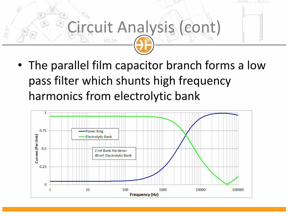
• The parallel film capacitor branch forms a low pass filter which shunts high frequency harmonics from electrolytic bank
Circuit Analysis (cont)
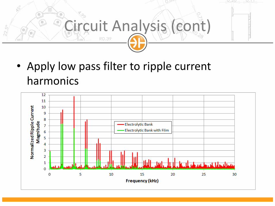
• Apply low pass filter to ripple current harmonics

Circuit Analysis (cont)
• The addition of 2mF film capacitor to a 40mF electrolytic bank has a significant effect…
– Power dissipated in the electrolytic bank is reduced by factor of 3
– Electrolytic bank RMS current is reduced to 60% of the original value
– Assuming a ripple current multiplier of 10 years for the original 40mF bank, the addition of the 2mF film capacitor will double the life to 20 years.
A Practical Illustration
• Consider a 500kW DC link capacitor which must handle 400Arms
– 1000V bus voltage requires 3x 500V electrolytic cans in series
– Using a standard 5.4mF building block, a total of 20 branches and 60 electrolyic cans are required to manage the current
– 36mF bank
Practical Illustration (cont)
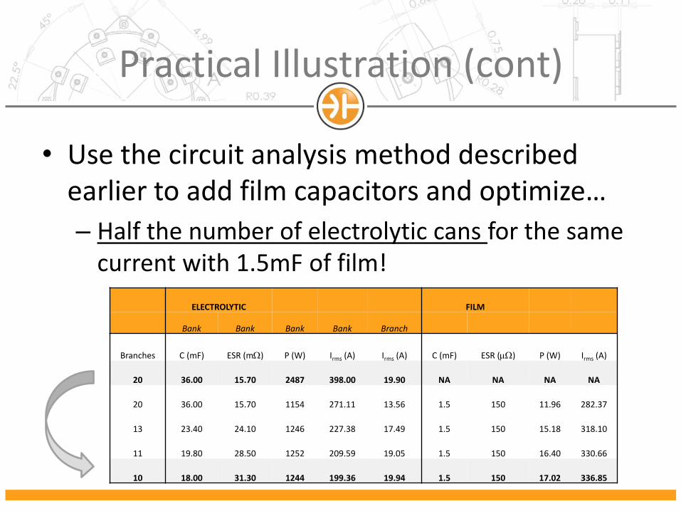
• Use the circuit analysis method described earlier to add film capacitors and optimize…
– Half the number of electrolytic cans for the same current with 1.5mF of film!
ELECTROLYTIC FILM
Bank Bank Bank Bank Branch
Branches C (mF) ESR (mW) P (W) Irms (A) Irms (A) C (mF) ESR (mW) P (W) Irms (A)
20 36.00 15.70 2487 398.00 19.90 NA NA NA NA
20 36.00 15.70 1154 271.11 13.56 1.5 150 11.96 282.37
13 23.40 24.10 1246 227.38 17.49 1.5 150 15.18 318.10
11 19.80 28.50 1252 209.59 19.05 1.5 150 16.40 330.66
10 18.00 31.30 1244 199.36 19.94 1.5 150 17.02 336.85
Practical Illustration (cont)
• This approach can only be effective if the film capacitor provides high reliability
– The SBE Power Ring Film Capacitor has optimal form factor with low ESR and thermal resistance for minimum hotspot temperature rise
• Two 0.75mF sections in parallel for 1.5mF film
– 2.3oC/W thermal resistance
– Losses are 8.5W = 75oC hotspot for 55oC ambient
– SBE Life data demonstrates MTTF > 300,000 hours
Practical Illustration (cont)
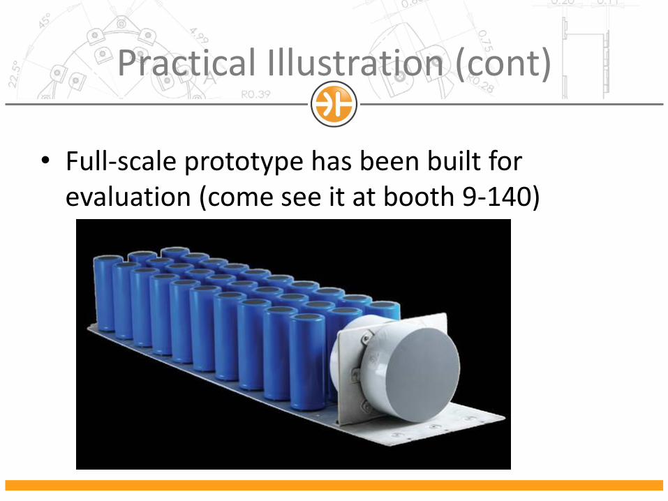
• Full-scale prototype has been built for evaluation (come see it at booth 9-140)
Practical Illustration (cont)
• Single pulse testing has been performed to evaluate effect of film capacitors on current extracted from the electrolytic bank
– Three car batteries in series charge bank to 36V
– Use a Fuji 2MBI225VN-120-50 (V Series) half-bridge to switch the capacitor bank into a low inductance 0.1 Ohm load
– Compare to simulation
Practical Illustration (cont)
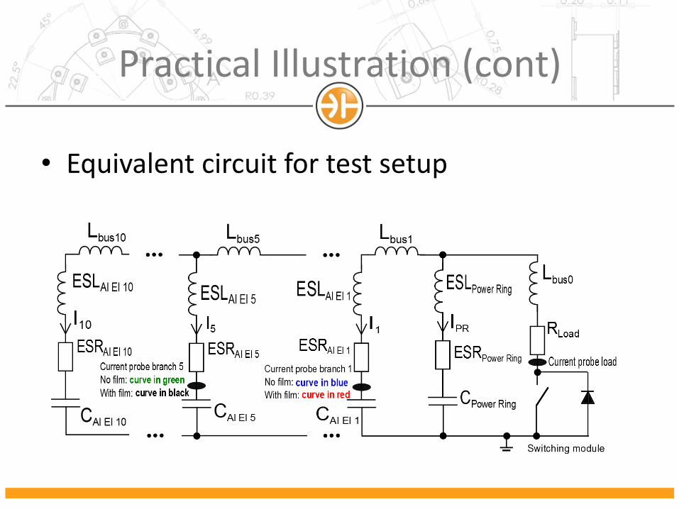
• Equivalent circuit for test setup
Practical Illustration (cont)
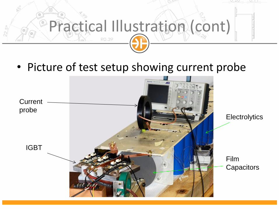
• Picture of test setup showing current probe
IGBT
Film
Capacitors
Electrolytics
Current
probe
Practical Illustration (cont)
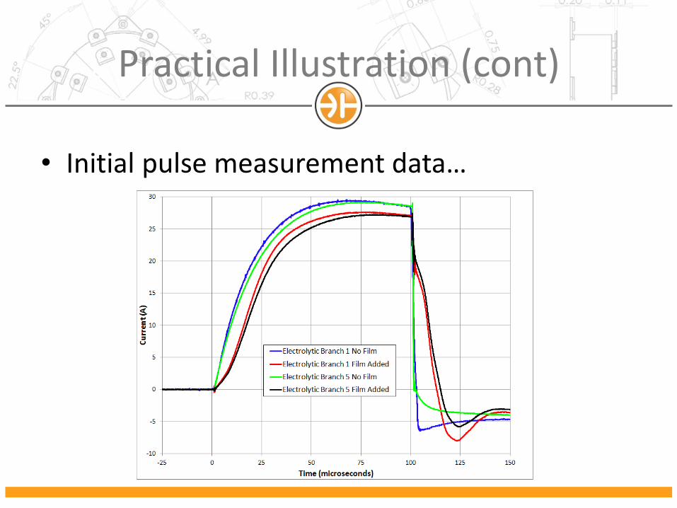
• Initial pulse measurement data…
Practical Illustration (cont)
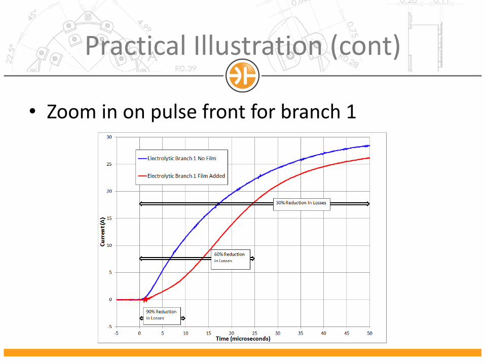
• Zoom in on pulse front for branch 1
Further Work
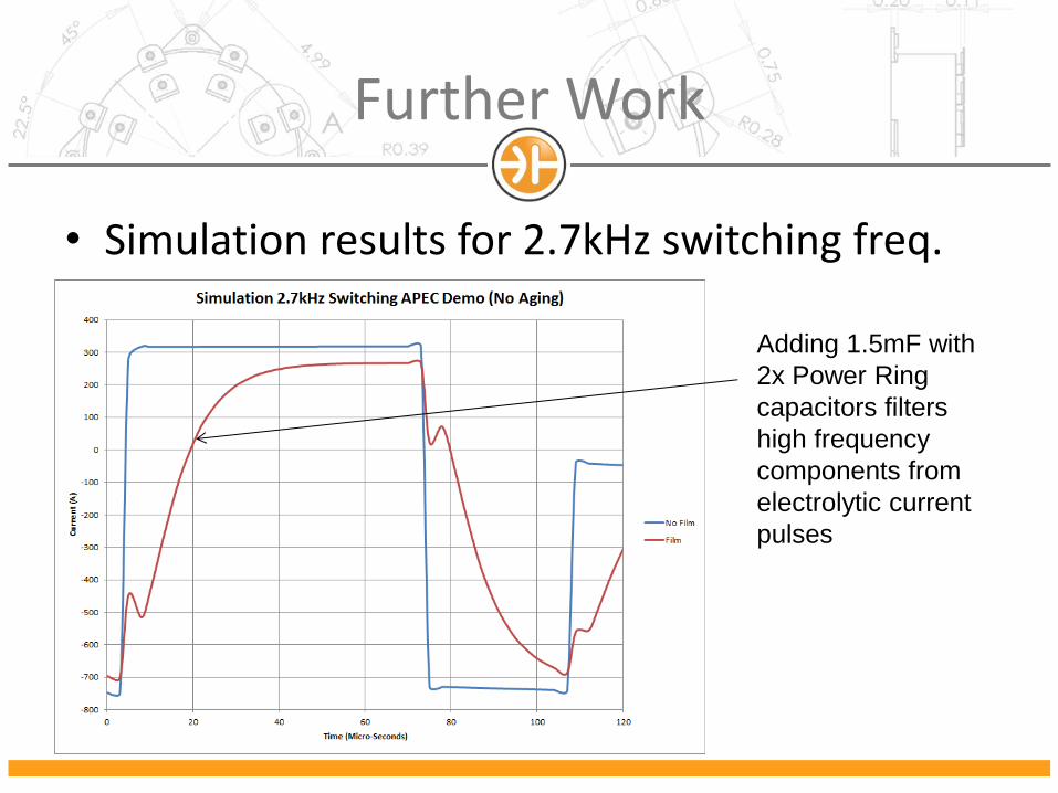
• Simulation results for 2.7kHz switching freq.
Adding 1.5mF with
2x Power Ring
capacitors filters
high frequency
components from
electrolytic current
pulses
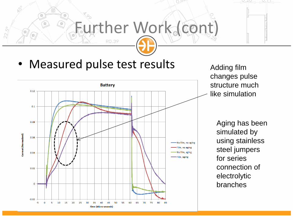
Further Work (cont)
• Measured pulse test results Adding film
changes pulse
structure much
like simulation
Aging has been
simulated by
using stainless
steel jumpers
for series
connection of
electrolytic
branches
Conclusion
• A hybrid DC link bank for alternative energy applications has been demonstrated
– Film handles high frequency ripple current
– Electrolytic manages slow energy storage
• The addition of a film capacitor “hardener” can significantly increase the life of an existing electrolytic bank
• A smaller electrolytic bank can be utilized for the same current rating with film

Questions?
• Thank you for attending
• We are looking for beta testing sites…