INCH-POUND MIL-DTL-12560K (MR) - Military Standards...
52
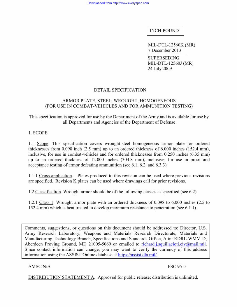
MIL-DTL-12560K (MR) 7 December 2013 . SUPERSEDING MIL-DTL-12560J (MR) 24 July 2009 DETAIL SPECIFICATION ARMOR PLATE, STEEL, WROUGHT, HOMOGENEOUS (FOR USE IN COMBAT-VEHICLES AND FOR AMMUNITION TESTING) This specification is approved for use by the Department of the Army and is available for use by all Departments and Agencies of the Department of Defense 1. SCOPE 1.1 Scope . This specification covers wrought-steel homogeneous armor plate for ordered thicknesses from 0.098 inch (2.5 mm) up to an ordered thickness of 6.000 inches (152.4 mm), inclusive, for use in combat-vehicles and for ordered thicknesses from 0.250 inches (6.35 mm) up to an ordered thickness of 12.000 inches (304.8 mm), inclusive, for use in proof and acceptance testing of armor defeating ammunition (see 6.1, 6.2, and 6.3.3). 1.1.1 Cross-application . Plates produced to this revision can be used where previous revisions are specified. Revision K plates can be used where drawings call for prior revisions. 1.2 Classification . Wrought armor should be of the following classes as specified (see 6.2). 1.2.1 Class 1 . Wrought armor plate with an ordered thickness of 0.098 to 6.000 inches (2.5 to 152.4 mm) which is heat treated to develop maximum resistance to penetration (see 6.1.1). AMSC N/A FSC 9515 DISTRIBUTION STATEMENT A . Approved for public release; distribution is unlimited. INCH-POUND Comments, suggestions, or questions on this document should be addressed to: Director, U.S. Army Research Laboratory, Weapons and Materials Research Directorate, Materials and Manufacturing Technology Branch, Specifications and Standards Office, Attn: RDRL-WMM-D, Aberdeen Proving Ground, MD 21005-5069 or emailed to [email protected] . Since contact information can change, you may want to verify the currency of this address information using the ASSIST Online database at https://assist.dla.mil/ . Downloaded from http://www.everyspec.com
Transcript of INCH-POUND MIL-DTL-12560K (MR) - Military Standards...
MIL-DTL-12560K (MR) 7 December 2013 .
SUPERSEDING MIL-DTL-12560J (MR) 24 July 2009
DETAIL SPECIFICATION
ARMOR PLATE, STEEL, WROUGHT, HOMOGENEOUS (FOR USE IN COMBAT-VEHICLES AND FOR AMMUNITION TESTING)
This specification is approved for use by the Department of the Army and is available for use by
all Departments and Agencies of the Department of Defense 1. SCOPE
1.1 Scope. This specification covers wrought-steel homogeneous armor plate for ordered thicknesses from 0.098 inch (2.5 mm) up to an ordered thickness of 6.000 inches (152.4 mm), inclusive, for use in combat-vehicles and for ordered thicknesses from 0.250 inches (6.35 mm) up to an ordered thickness of 12.000 inches (304.8 mm), inclusive, for use in proof and acceptance testing of armor defeating ammunition (see 6.1, 6.2, and 6.3.3). 1.1.1 Cross-application. Plates produced to this revision can be used where previous revisions are specified. Revision K plates can be used where drawings call for prior revisions. 1.2 Classification. Wrought armor should be of the following classes as specified (see 6.2). 1.2.1 Class 1. Wrought armor plate with an ordered thickness of 0.098 to 6.000 inches (2.5 to 152.4 mm) which is heat treated to develop maximum resistance to penetration (see 6.1.1). AMSC N/A FSC 9515 DISTRIBUTION STATEMENT A. Approved for public release; distribution is unlimited.
INCH-POUND
Comments, suggestions, or questions on this document should be addressed to: Director, U.S. Army Research Laboratory, Weapons and Materials Research Directorate, Materials and Manufacturing Technology Branch, Specifications and Standards Office, Attn: RDRL-WMM-D, Aberdeen Proving Ground, MD 21005-5069 or emailed to [email protected]. Since contact information can change, you may want to verify the currency of this address information using the ASSIST Online database at https://assist.dla.mil/.
Downloaded from http://www.everyspec.com
MIL-DTL-12560K (MR)
2
1.2.2 Class 2. Wrought armor plate with an ordered thickness of 0.098 to 2.000 inches (2.5 to 50.8mm) which is heat treated to develop maximum resistance to shock (see 6.1.2). 1.2.3 Class 3. Wrought armor plate with an ordered thickness of 0.250 to 12.000 inches (6.35 to 304.8 mm) which is heat treated to develop specific hardness and impact values for evaluation of armor-defeating ammunition only. This class of armor is not intended for use in combat-vehicles. To meet the thickness tolerances of this class of armor special surface finishing may be required (see 6.1.3). 1.2.4 Class 4a. Wrought armor plate with an ordered thickness of 0.098 to 2.750 inches (2.5 to 69.9 mm) which is designed for better resistance to penetration with respect to Class 1 (see 6.1.4) 1.2.5 Class 4b. Wrought armor plate that is air hardened and auto-tempered with an ordered thickness of 0.098 to 2.750 inches (2.5 to 69.9 mm) which is designed for better resistance to penetration with respect to Class 1 (see 6.1.5) 2. APPLICABLE DOCUMENTS
2.1 General. The documents listed in this section are specified in sections 3, 4, or 5 of this specification. This section does not include documents cited in other sections of this specification or recommended for additional information or as examples. While every effort has been made to ensure the completeness of this list, document users are cautioned that they must meet all specified requirements of documents cited in sections 3, 4, or 5 of this specification, whether or not they are listed. 2.2 Government documents. 2.2.1 Specifications, standards, and handbooks. The following specifications, standards, and handbooks form a part of this document to the extent specified herein. Unless otherwise specified, the issues of these documents are those cited in the solicitation or contract. INTERNATIONAL STANDARDIZATION AGREEMENTS ISO 9712 - Non-Destructive Testing - Qualification and Certification of NDT Personnel (Copies of this document are available from http://www.iso.ch or from the International Organization for Standardization American National Standards Institute 11 West 42nd Street, 13th Floor New York, New York, United States, 10036.) DEPARTMENT OF DEFENSE STANDARDS
MIL-STD-129 - Military Marking for Shipment and Storage
(Copies of these documents are available online at http://quicksearch.dla.mil/ or https://assist.dla.mil or from the Standardization Document Order Desk, 700 Robbins Avenue, Building 4D, Philadelphia, PA 19111-5094.)
Downloaded from http://www.everyspec.com
MIL-DTL-12560K (MR)
3
2.2.2 Other Government documents, drawings, and publications. The following other Government documents, drawings, and publications form a part of this document to the extent specified herein. Unless otherwise specified, the issues of these documents are those cited in the solicitation or contract. USADTC TOP 2-2-710 - Ballistic Tests of Armor Materials ITOP 2-2-713 - Ballistic Testing of Armor (Application for copies is available online at http://www.dtic.mil/ or from the Defense Technical Information Center, 8725 John J. Kingman Road, Suite 0944, Fort Belvoir, VA 22060-6218.) 2.3 Non-Government publications. The following documents form a part of this document to the extent specified herein. Unless otherwise specified, the issues of these documents are those cited in the solicitation or contract. ASTM INTERNATIONAL
ASTM A6/A6M - Standard Specification for General Requirements for Rolled Structural Steel Bars, Plates, Shapes and Sheet Piling ASTM A370 - Standard Test Methods and Definitions for Mechanical Testing of Steel Products
ASTM A578/ A578M - Standard Specification for Straight-Beam Ultrasonic Examination of Plain and Clad Steel Plates for Special Applications ASTM A751 - Standard Test Methods, Practices, and Terminology for Chemical Analysis of Steel Products
ASTM E10 - Standard Test Method for Brinell Hardness of Metallic Materials
ASTM E23 - Standard Test Methods for Notched Bar Impact Testing of Metallic Materials
ASTM E110 - Standard Test Method for Indentation Hardness of Metallic Materials by Portable Hardness Testers
ASTM E290 - Standard Test Methods for Bend Testing of Material for Ductility
ASTM E1077 - Standard Test Methods for Estimating the Depth of Decarburization of Steel Specimens ASTM E1444 - Standard Practice for Magnetic Particle Testing (Copies of these documents are available from www.astm.org or ASTM International, 100 Barr Harbor Drive, P.O. Box C700, West Conshohocken, PA 19428-2959.) 2.4 Order of precedence. Unless otherwise noted herein or in the contract, in the event of a conflict between the text of this document and the references cited herein, the text of this document takes precedence. Nothing in this document, however, supersedes applicable laws and regulations unless a specific exemption has been obtained.
Downloaded from http://www.everyspec.com
MIL-DTL-12560K (MR)
4
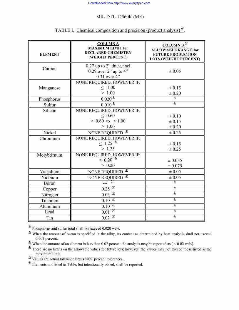
3. REQUIREMENTS 3.1 First Article. When specified in the contract or purchase order (see 6.2, 6.5 and 6.9), a sample or samples of the specified item shall be made available to the contracting officer or his authorized representative for approval in accordance with 4.4. The contractor shall comply with this requirement at the time of his first order or contract and at any time that the supplier has not furnished the same class of wrought armor plate in the applicable thickness range under this specification within a period of 37 months. The approval of the first article samples authorizes the commencement of shipment but does not relieve the supplier of responsibility for compliance with all applicable provisions of this specification, namely conformance or production acceptance. The first article samples and test plates shall be manufactured by the process proposed for use on production armor. This process shall be inspected by a cognizant government representative to ensure compliance with the details of this specification. The manufacturer's declared chemical analysis shall be submitted to the contracting agency and to the ballistic test agency. The ballistic test agency shall record the first article ballistic test plates submitted, showing the dates tested. Requests from the procuring activity to the ballistic test agency as to prior conformance with first article tests shall be accompanied by copies of the first article test firing records. Any deviation(s) noticed by the ballistic agency shall be brought to the attention of the contracting activity and to the manufacturer. 3.1.1 First time producer. First time producers wishing to qualify to this specification shall follow the instructions of 6.7. 3.2 Production acceptance. 3.2.1 Chemical composition. A declared chemistry shall be submitted to the contracting agency or its authorized representative and to the ballistic test agency. The chemical composition of the declared chemistry shall conform to the requirements of Table I, column A, unless otherwise specified in the contract or purchase order (see 6.2). If an analysis of Antimony, Arsenic or Lead is required, it shall be specified in the contract or purchase order (see 6.2). A single heat cannot be dual certified to both MIL-DTL-12560 and MIL-DTL-46100. The chemical composition shall be determined by a product analysis (values shall be listed as weight percent) in accordance with 4.6.1.1 and 4.8.1. The first article samples and the production test plates shall utilize the same declared chemistry within the allowable ranges proposed for use in production. A statement showing the heat analysis of each melt and one product analysis of each lot, complete details of the heat treatment, and all mechanical properties of each lot of production plates shall be furnished for the files of the purchaser at no cost. All elements of the chemical composition specified in Table I shall be shown in the statement. This statement shall be attached to the completed Rolled Homogeneous Armor Test Data Form (see Figure 1), or other certifications containing the same information. 3.2.2 Carbon equivalence. Carbon equivalence (CE) shall be calculated for each heat per ASTM A6/A6M, i.e. CE = C + [Mn/6] + [(Cr + Mo + V)/5] + [(Ni + Cu)/15]
where the elements are expressed in wt%.
Downloaded from http://www.everyspec.com
MIL-DTL-12560K (MR)
5
TABLE I. Chemical composition and precision (product analysis) 6/.
ELEMENT
COLUMN A MAXIMUM LIMIT for
DECLARED CHEMISTRY (WEIGHT PERCENT)
COLUMN B 5/ ALLOWABLE RANGE for FUTURE PRODUCTION
LOTS (WEIGHT PERCENT)
Carbon
0.27 up to 2” thick, incl 0.29 over 2” up to 4”
0.31 over 4” ± 0.05
Manganese NONE REQUIRED, HOWEVER IF:
< 1.00 > 1.00
± 0.15 ± 0.20
Phosphorus 0.020 1/ 4/ Sulfur 0.010 1/ 4/ Silicon NONE REQUIRED, HOWEVER IF:
< 0.60 > 0.60 to < 1.00
> 1.00
± 0.10 ± 0.15 ± 0.20
Nickel NONE REQUIRED 3/ ± 0.25 Chromium NONE REQUIRED, HOWEVER IF:
< 1.25 3/ > 1.25
± 0.15 ± 0.25
Molybdenum NONE REQUIRED, HOWEVER IF: < 0.20 3/
> 0.20
± 0.035 ± 0.075
Vanadium NONE REQUIRED 3/ ± 0.05 Niobium NONE REQUIRED 3/ ± 0.05
Boron --- 2/ 4/ Copper 0.25 3/ 4/
Nitrogen 0.03 3/ 4/ Titanium 0.10 3/ 4/
Aluminum 0.10 3/ 4/ Lead 0.01 3/ 4/ Tin 0.02 3/ 4/
1/ Phosphorus and sulfur total shall not exceed 0.020 wt%. 2/ When the amount of boron is specified in the alloy, its content as determined by heat analysis shall not exceed 0.003 percent. 3/ When the amount of an element is less than 0.02 percent the analysis may be reported as [ < 0.02 wt%]. 4/ There are no limits on the allowable values for future lots; however, the values may not exceed those listed as the maximum limit. 5/ Values are actual tolerance limits NOT percent tolerances. 6/ Elements not listed in Table, but intentionally added, shall be reported.
Downloaded from http://www.everyspec.com
MIL-DTL-12560K (MR)
6
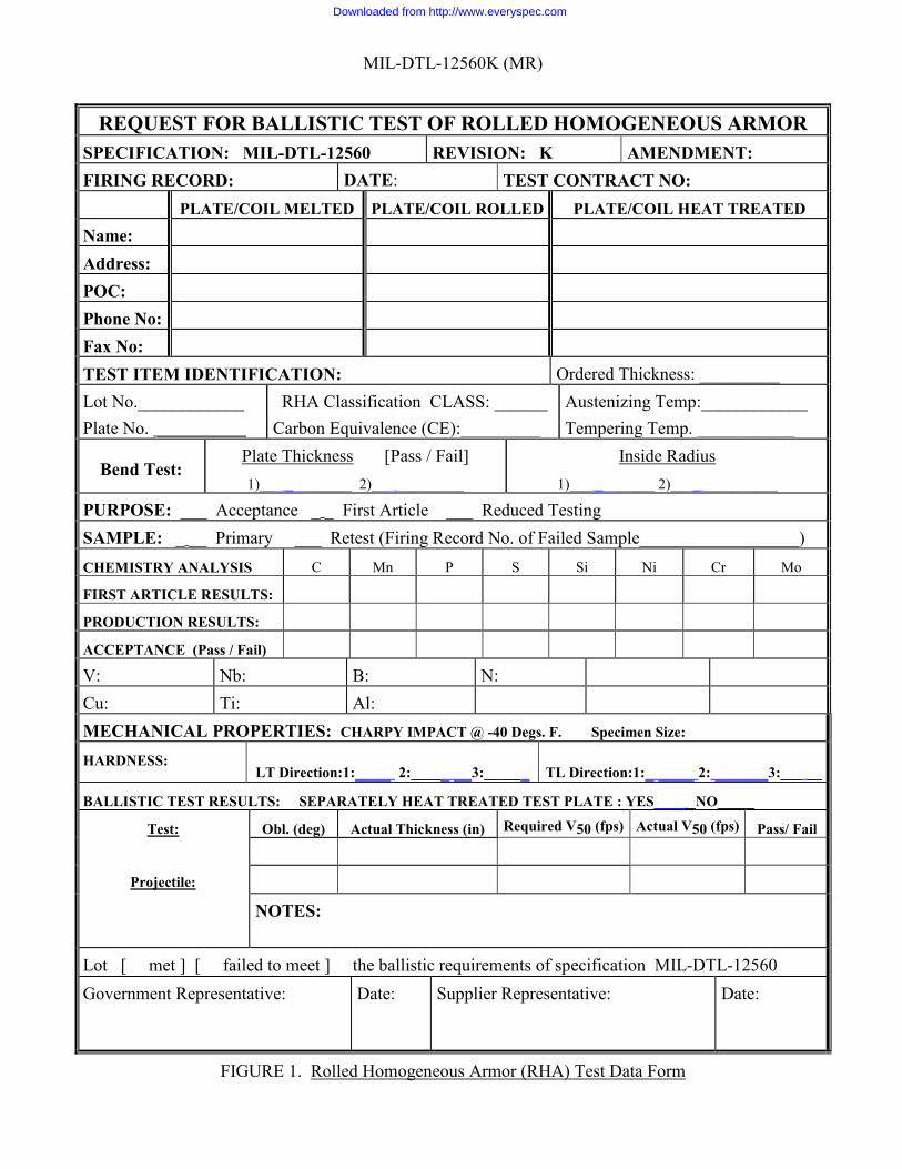
REQUEST FOR BALLISTIC TEST OF ROLLED HOMOGENEOUS ARMOR SPECIFICATION: MIL-DTL-12560 REVISION: K AMENDMENT: FIRING RECORD: DATE: TEST CONTRACT NO: PLATE/COIL MELTED PLATE/COIL ROLLED PLATE/COIL HEAT TREATED
Name: Address: POC: Phone No: Fax No: TEST ITEM IDENTIFICATION: Ordered Thickness: _________ Lot No.____________ Plate No. __________
RHA Classification CLASS: ______ Carbon Equivalence (CE):_________
Austenizing Temp:____________ Tempering Temp. ___________
Bend Test: Plate Thickness [Pass / Fail] 1)___ _________ 2)___ _________
Inside Radius 1)___ ________ 2)____ __________
PURPOSE: ___ Acceptance _ _ First Article ___ Reduced Testing SAMPLE: _ __ Primary ___ Retest (Firing Record No. of Failed Sample__________________) CHEMISTRY ANALYSIS C Mn P S Si Ni Cr Mo
FIRST ARTICLE RESULTS:
PRODUCTION RESULTS:
ACCEPTANCE (Pass / Fail)
V: Nb: B: N: Cu: Ti: Al: MECHANICAL PROPERTIES: CHARPY IMPACT @ -40 Degs. F. Specimen Size: HARDNESS:
LT Direction:1:____ 2:_____ __3:______ TL Direction:1:_ ____ 2: ______3:___ __
BALLISTIC TEST RESULTS: SEPARATELY HEAT TREATED TEST PLATE : YES____ _NO_____
Test:
Projectile:
Obl. (deg) Actual Thickness (in) Required V50 (fps) Actual V50 (fps) Pass/ Fail
NOTES:
Lot [ met ] [ failed to meet ] the ballistic requirements of specification MIL-DTL-12560
Government Representative: Date:
Supplier Representative:
Date:
FIGURE 1. Rolled Homogeneous Armor (RHA) Test Data Form
Downloaded from http://www.everyspec.com
MIL-DTL-12560K (MR)
7
3.2.2.1 Class 1 & 2. Class 1 and 2 steel shall have a CE of less than 0.80 wt% for plates less than 2 inches in thickness. For plates 2 to 4 inches shall have a CE of less than 0.85 wt%. For plates greater than 4 inches in thickness shall have a CE of 0.90 wt% or less. 3.2.2.2 Class 3. Class 3 steel shall have no CE limit unless otherwise specified in the contract or purchase order (see 6.2). 3.2.2.3 Class 4a. Class 4a steel shall have a CE limit of less than 0.70 wt% unless otherwise specified in the contract or purchase order (see 6.2). 3.2.2.4 Class 4b. Class 4b steel shall have no CE limit unless otherwise specified in the contract or purchase order (see 6.2). 3.2.3 Heat treatment. All plates in each lot, including samples, shall receive the same heat treatment except for such variations in tempering temperature as shall be necessary to produce the prescribed hardness. The austenitizing temperature for production plates may vary within a range of 50° above the temperature used for test plates, but in no case shall the plate surface exceed 1800°F (see 6.6). 3.2.4 Condition. Unless otherwise specified in the contract or purchase order (see 6.2), plates shall be in the as-heat treated condition. If descaling is required it shall be as specified in the contract or purchase order (see 6.2). Plates shall not be pickled. 3.2.5 Processing controls. 3.2.5.1 Furnace survey requirements of heat treating furnaces. All furnaces that are used to heat treat plates must be thermally surveyed. The initial survey is done once using the thinnest and thickest gage plate. This shall be followed with annual surveys using any gage. 3.2.5.1.1 Thermal survey requirements of heat treating furnaces. Thermal surveys are conducted as follows:
a. Three contact thermocouples must be used, both edges and in the middle across the width of the plate. b. A calibrated recording device and thermocouples must be used. c. The test plate is run through the furnace using standard hold times. d. Trial starts when plate exits heat-up zones, and ends when plate exits furnace. e. Maximum temperature variability when plate is in soaking zones is +/- 25°F for tempering furnaces and +/- 50°F for austenitizing furnaces.
3.2.5.2 Heating. Stress relieving the plates, local or general, shall be allowed after final quenching and tempering at a maximum temperature of 50°F below the tempering temperature. Plates shall not be stress relieved in a temperature range of 500-700°F. After stress relieving, the plates shall be tested for hardness and shall meet the requirements of Table II. 3.2.5.3 Repairing. 3.2.5.3.1 Weld repair of mill defects after final heat treatment. Unless otherwise specified in the contract or purchase order (see 6.2), weld repair after final heat treatment shall be permitted for
Downloaded from http://www.everyspec.com
MIL-DTL-12560K (MR)
8
plates with an ordered thickness greater than 2 inches. Mill imperfections may be repair welded by the contractor or referred to the contracting activity for acceptance with subsequent repair welding to be performed by the contracting activity. The following limitations shall apply to all weld repairs:
a. The total area to be repaired shall not exceed 0.1 percent of the surface of one side of the plate.
b. The depth of any area to be repaired shall not exceed one-tenth the ordered thickness of the plate or 1/4 inch, whichever is less. The depth of the area to be repaired shall be a minimum of 0.030 inch.
c. Maximum size of each weld repaired area is 0.375” diameter. d. Areas to be welded shall be ground to assure that the welds are made on clean, sound
metal. e. After preparation for repair and prior to welding, the depressed area shall be magnetic
particle inspected in accordance with ASTM E1444, and shown to be free of linear discontinuities.
f. Weld repairs shall be made in accordance with a welding procedure qualified in accordance with drawing 19207-12479550, entitled: “GROUND COMBAT VEHICLE WELDING CODE – STEEL” or MIL-HDBK-1941 or the applicable fabrication document.
g. Weld filler metal shall have a minimum UTS of 100 ksi. h. The final repaired surface shall be ground smooth and flush with the adjacent surface. The
finished weld surface shall also be free of under-fill. i. Surface weld repairs shall be magnetic particle inspected after final grinding (or subsequent
heat treatment, if applicable) in accordance with ASTM E1444. Welds and adjacent heat affected zone surfaces shall be free of relevant linear indications longer than 1/8 inch.
j. Repaired areas shall be marked. The markings shall remain legible and shall not be removed prior to performing all inspections specified herein.
k. Notation of such repaired areas and the type of welding filler metal used to make the weld repair(s) shall be made on the plate inspection form as part of the records.
l. If a non-heat treatable electrode is used, reheat treatment of the plate is prohibited.
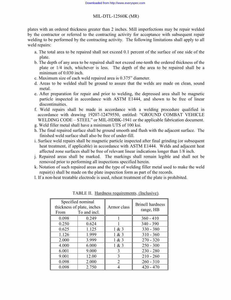
TABLE II. Hardness requirements. (Inclusive).
Specified nominal thickness of plate, inches From To and incl.
Armor class Brinell hardness range, HB
0.098 0.249 1 360 - 410 0.250 0.624 1 340 - 390 0.625 1.125 1 & 3 330 - 380 1.126 1.999 1 & 3 310 - 360 2.000 3.999 1 & 3 270 - 320 4.000 6.000 1 & 3 250 - 300 6.001 9.000 3 230 - 280 9.001 12.00 3 210 - 260 0.098 2.000 2 260 - 310 0.098 2.750 4 420 - 470
Downloaded from http://www.everyspec.com
MIL-DTL-12560K (MR)
9
3.2.5.3.2 Weld repairs of mill defects prior to heat treatment. Unless otherwise specified in the contract or purchase order (see 6.2), weld repair prior to final heat treatment shall be permitted for plates with an ordered thickness greater than 0.250 inch. Weld repairs of mill imperfections may be accomplished prior to heat treatment within the limitations as specified in 3.2.5.3.1, except such weld repairs shall be made using a heat-treatable filler material. 3.2.5.4 Grinding. Grinding is not required but may be performed to remove minor defects not affecting the serviceability of the material provided that, unless otherwise authorized by the procuring activity, the grinding does not result in the reduction of the plate thickness in the ground area to less than the tolerances specified in Table III.
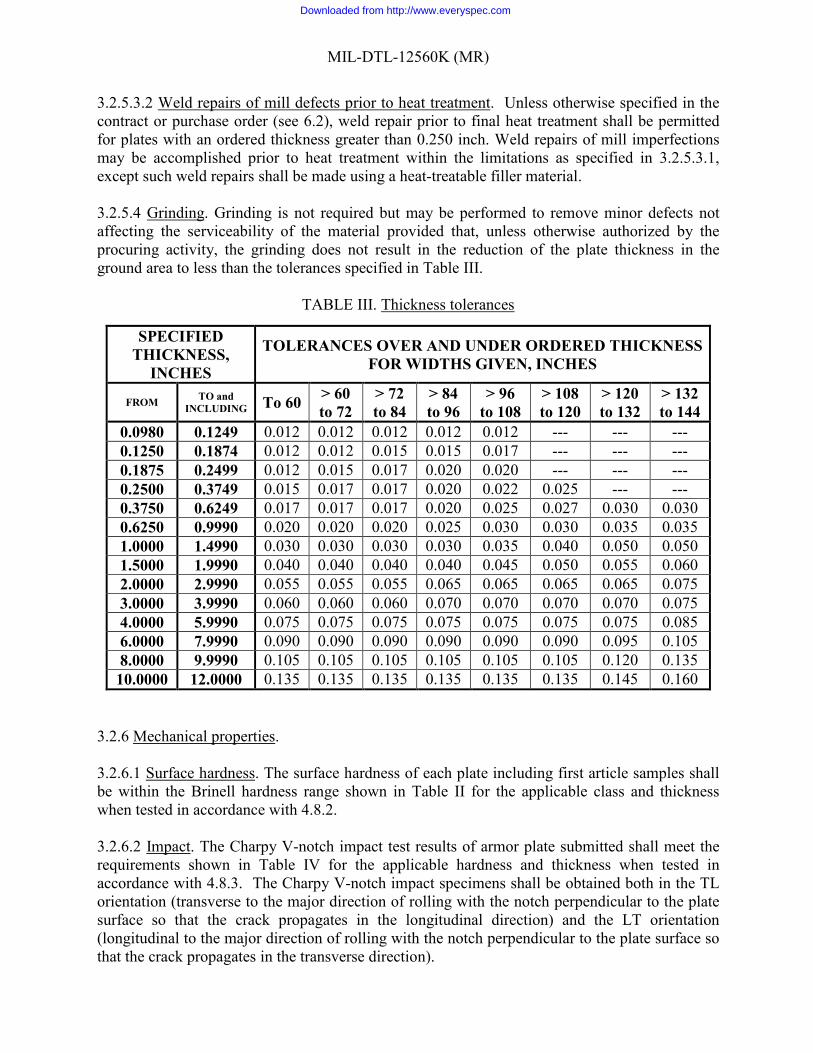
TABLE III. Thickness tolerances
3.2.6 Mechanical properties.
3.2.6.1 Surface hardness. The surface hardness of each plate including first article samples shall be within the Brinell hardness range shown in Table II for the applicable class and thickness when tested in accordance with 4.8.2.
3.2.6.2 Impact. The Charpy V-notch impact test results of armor plate submitted shall meet the requirements shown in Table IV for the applicable hardness and thickness when tested in accordance with 4.8.3. The Charpy V-notch impact specimens shall be obtained both in the TL orientation (transverse to the major direction of rolling with the notch perpendicular to the plate surface so that the crack propagates in the longitudinal direction) and the LT orientation (longitudinal to the major direction of rolling with the notch perpendicular to the plate surface so that the crack propagates in the transverse direction).
SPECIFIED THICKNESS,
INCHES
TOLERANCES OVER AND UNDER ORDERED THICKNESS FOR WIDTHS GIVEN, INCHES
FROM TO and INCLUDING To 60
> 60 to 72
> 72 to 84
> 84 to 96
> 96 to 108
> 108 to 120
> 120 to 132
> 132 to 144
0.0980 0.1249 0.012 0.012 0.012 0.012 0.012 --- --- --- 0.1250 0.1874 0.012 0.012 0.015 0.015 0.017 --- --- --- 0.1875 0.2499 0.012 0.015 0.017 0.020 0.020 --- --- --- 0.2500 0.3749 0.015 0.017 0.017 0.020 0.022 0.025 --- --- 0.3750 0.6249 0.017 0.017 0.017 0.020 0.025 0.027 0.030 0.030 0.6250 0.9990 0.020 0.020 0.020 0.025 0.030 0.030 0.035 0.035 1.0000 1.4990 0.030 0.030 0.030 0.030 0.035 0.040 0.050 0.050 1.5000 1.9990 0.040 0.040 0.040 0.040 0.045 0.050 0.055 0.060 2.0000 2.9990 0.055 0.055 0.055 0.065 0.065 0.065 0.065 0.075 3.0000 3.9990 0.060 0.060 0.060 0.070 0.070 0.070 0.070 0.075 4.0000 5.9990 0.075 0.075 0.075 0.075 0.075 0.075 0.075 0.085 6.0000 7.9990 0.090 0.090 0.090 0.090 0.090 0.090 0.095 0.105 8.0000 9.9990 0.105 0.105 0.105 0.105 0.105 0.105 0.120 0.135 10.0000 12.0000 0.135 0.135 0.135 0.135 0.135 0.135 0.145 0.160
Downloaded from http://www.everyspec.com
MIL-DTL-12560K (MR)
10
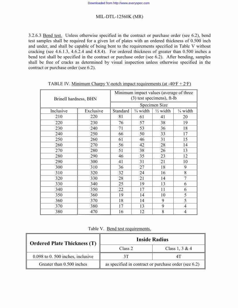
3.2.6.3 Bend test. Unless otherwise specified in the contract or purchase order (see 6.2), bend test samples shall be required for a given lot of plates with an ordered thickness of 0.500 inch and under, and shall be capable of being bent to the requirements specified in Table V without cracking (see 4.6.1.3, 4.6.2.4 and 4.8.4). For ordered thickness of greater than 0.500 inches a bend test shall be specified in the contract or purchase order (see 6.2). After bending, samples shall be free of cracks as determined by visual inspection unless otherwise specified in the contract or purchase order (see 6.2).
TABLE IV. Minimum Charpy V-notch impact requirements (at -40oF + 2oF)
Table V. Bend test requirements.
Ordered Plate Thickness (T) Inside Radius
Class 2 Class 1, 3 & 4
0.098 to 0. 500 inches, inclusive 3T 4T Greater than 0.500 inches as specified in contract or purchase order (see 6.2)
Brinell hardness, BHN Minimum impact values (average of three
(3) test specimens), ft-lb Specimen Size
Inclusive Exclusive Standard ¾ width ½ width ¼ width 210 220 81 61 41 20 220 230 76 57 38 19 230 240 71 53 36 18 240 250 66 50 33 17 250 260 61 46 31 15 260 270 56 42 28 14 270 280 51 38 26 13 280 290 46 35 23 12 290 300 41 31 21 10 300 310 36 27 18 9 310 320 32 24 16 8 320 330 28 21 14 7 330 340 25 19 13 6 340 350 22 17 11 6 350 360 19 14 10 5 360 370 18 14 9 5 370 380 17 13 9 4 380 470 16 12 8 4
Downloaded from http://www.everyspec.com
MIL-DTL-12560K (MR)
11
3.2.7 Ballistic requirements. Ballistic requirements shall be in accordance with the Appendix A of this specification. When a complete penetration cannot be obtained, the following rule shall be in effect until a new ballistic acceptance round can be utilized. When four (4) partial penetrations are above the minimum requirement for the specific thickness, the material shall be certified as acceptable with a V50 (which obviously cannot be specified) above the minimum requirement. There are no ballistic test requirements for class 2 plate thicker than 1.000 inch. 3.2.7.1 Ballistic test plate information. For each lot of armor plate a properly completed Rolled Homogeneous Armor (RHA) Test Data Form (see Figure 1) shall be submitted with each ballistic test plate that represents that particular processing lot. 3.2.8 Dimensions and tolerances. 3.2.8.1 Dimensions. Armor plates shall comply with the dimensions specified in the applicable drawings or in the contract or purchase order (see 6.2). Unless otherwise specified in the contract or order (see 6.2), dimensional tolerances will be in accordance with Table III. Armor plate tolerances on length and width dimensions shall be plus 2 inches and minus zero. 3.2.8.2 Thickness. 3.2.8.2.1 Thickness measurements (class 3 armor). The thickness of all class 3 plates shall be determined by measurements made one foot on centers over the entire surface of each plate. The measurements shall be to the nearest thousandth of an inch. The acceptance of each plate shall be based on these measurements meeting the thickness requirements of Table III. 3.2.8.2.2 Thickness tolerances. The thickness tolerances of each plate, after final treatment, shall be in accordance with Table III. The contract or purchase order (see 6.2) shall specify the thickness tolerance when not specified in Table III. 3.2.8.3 Flatness. Unless otherwise specified in the contract or order (see 6.2), the flatness tolerance of each plate shall be within one-half of the tolerance listed in ASTM A6/A6M (As of the release date of MIL-DTL-12560K (MR), the appropriate table is Table 14, however, this table may be re-numbered during a future revision or update, so caution should be taken by the user). Tighter tolerance requirements shall be specified in the contract or purchase order (see 6.2) and shall be as agreed upon between the contractor and the procuring activity. 3.2.8.4 Waviness. The permitted variation in waviness is a function of the permitted variation from a flat surface as obtained from Table 14 in ASTM A6/A6M. Unless otherwise specified in the contract or purchase order (see 6.2), the waviness tolerance of each plate shall be one-half the tolerance listed in ASTM A6/A6M Table 15, using the applicable full tolerance obtained from the flatness tolerance table (Table 14) for the appropriate plate thickness and width. The one-half tolerance reduction shall not be applied to both the flatness table and the waviness table to determine waviness tolerance. (As of the release date of MIL-DTL-12560K (MR), the appropriate table is Table 15, with reference to Table 14, however, these tables may be re-numbered during a future revision or update to ASTM A6/A6M, so caution should be taken by the user).
Downloaded from http://www.everyspec.com
MIL-DTL-12560K (MR)
12
3.2.9 Identification marking. Identification marking and records shall be such as to ensure positive identification of all plates, including test samples and specimens, with the lot and corresponding heat from which they were produced. The primary plate rolling direction shall be identified. 3.2.9.1 Class 3 armor plate identification marking. Manufacturers supplying class 3 armor plate are additionally required to:
a. Mark each class 3 plate with one foot square blocks showing thickness at the center of each block. The acceptance of each plate shall be based on these measurements meeting the thickness requirements set forth in Table III.
b. Label each plate “RHA, class 3, MIL-A-12560, plate No. ____, heat No.____.” Labeling shall be approximately 1/2 inch high letters. Location of labeling for all plates shall be in the upper right hand corner.
3.2.9.2 Ballistic test plate identification marking. First article and acceptance ballistic test plates shall also be marked with unique melt and slab, the manufacture’s name or trademark, the number and class of this specification, and the ordered plate thickness in inches. First article plates shall be marked “PRE,” acceptance plates “ACC,” and retest plates shall be marked “R1” and “R2.” If a second set of retest plates are submitted they shall be marked “RR1” and “RR2.” All plate markings shall be approximately 1/2 inch high letters and highlighted with a highly visible paint. The primary plate rolling direction shall be identified. 3.2.10 Information required. A statement showing the product analysis of each melt and complete details of the heat treatment of each lot shall be furnished for the files of the procuring activity in addition to the completed Rolled Homogeneous Armor (RHA) Test Data Form (see Figure 1). All elements of the chemical composition shall be shown in the statement, including special additives or hardening agents, whether shown in Table I or not. 3.2.11 Workmanship.
3.2.11.1 Surface imperfections. When specified in the contract or purchase order (see 6.2), plates shall be inspected for surface imperfections in the de-scaled condition, only. The top and bottom surface of each plate shall be free from the following surface defects: slivers, laps, checks, seams, blisters, snakes, cold shuts, cracks, burning, and laminations (see 6.3). Imperfections listed above which are of such nature as to affect the fabrication of the material, are rejectable. 3.2.11.1.1 Depth of imperfections. The depth of rolled-in scale, scale pitting, mechanical gouges, or snakes shall not exceed 0.015 inch and shall not reduce the steel thickness below the allowable minimum. Isolated individual pits over 0.015 inch deep and not within 6 inches of each other and which do not violate the minimum allowable thickness, as specified in Table III or the applicable drawings and fabrication documents, are acceptable. Additionally, if isolated individual pits do not lie within 4 feet of each other and have a depth of less than 4% of ordered gage, and less than 0.25 inch in diameter, are acceptable. 3.2.11.2 Edge preparation. Thermal cutting shall be permitted after final heat treatment provided the procedure, which may include grinding after thermal cutting, is such that no cracks develop
Downloaded from http://www.everyspec.com
MIL-DTL-12560K (MR)
13
on any thermally cut edge whether detected by nondestructive inspection, or as agreed upon in the contract. The heat affected zone of thermally cut plates (up to and including 1/2 inch in thickness) shall not exceed 1.2 times the plate’s thickness from the cut edge. For plates over 1/2 inch thick, the heat affected zone shall not exceed 5/8 inch from the cut edge. In order to have the heat affected zone exceed these limits approval shall be obtained from the procuring activity and shall be as specified in the contract or purchase order (see 6.2). Supplier must demonstrate this capability to the procuring activity during First Article Testing. 3.2.11.3 Edge condition. Plate edge on plates delivered after heat treatment shall be free of cracks. The supplier shall practice such necessary process controls to prevent this condition. 3.2.11.4 Internal soundness. Ultrasonic testing is not required for plates with an ordered thickness that is less than or equal to 0.625 inch gauge. Plates over 0.625 inch must be ultrasonically tested unless supplier can prove substantial plates in the 0.626 to 2.00 inch gauge range have been ultrasonically tested in the past without findings. If supplier can demonstrate excellent internal soundness history, then only one plate from every lot with an ordered thickness between 0.626 and 2.000 inches shall be ultrasonically examined for internal soundness in accordance with 4.7.3. Every plate from every lot that has an ordered thickness greater than 2 inches shall be ultrasonically examined for internal soundness in accordance with 4.7.3. The acceptance level shall be C, unless otherwise specified in the contract or purchase order (see 6.2). 3.2.11.4.1 Acceptance criteria. 3.2.11.4.1.1 Single linear indications. In any four inches of length a single linear indication shall not exceed twice the plate thickness. 3.2.11.4.1.2 Multiple linear indications. Multiple linear indications shall not exceed 1-1/2 times the plate thickness if two or more lie in the same plane. The total length of indications in one plane, in any four inch length, shall not exceed twice the plate thickness. No more than ten indications, whether in one plane or multiple planes, are permitted in any four inch length. 3.2.11.4.1.3 Cracks. All cracks shall be rejectable (see 6.3.18 for definition). 3.2.11.4.1.4 Removal of large indications. Large indications shall be removed by the manufacturer or processor by grinding, or weld repair as specified in 3.2.5.3. 4. VERIFICATION 4.1 Classification of inspection. The inspection requirements specified herein are classified as follows:
a. First article inspection (see 4.4). b. Production acceptance inspection (see 4.5).
4.2 Testing responsibility and facilities. Unless otherwise specified in the contract or purchase order (see 6.2), the contractor is responsible for the performance of all the requirements as specified herein. Unless otherwise specified in the contract or purchase order (see 6.2), the contractor may use his own or any other facilities suitable for the performance of the
Downloaded from http://www.everyspec.com

MIL-DTL-12560K (MR)
14
requirements specified herein, except ballistic tests (see 4.2.1), unless disapproved by the Government. The Government reserves the right to perform or check any of the inspections set forth in this specification where such inspections are deemed necessary to assure supplies and services conform to prescribed requirements and to determine the validity of the certifications. 4.2.1 Ballistic testing facility. Unless otherwise specified in the contract or purchase order (see 6.2), the ballistic test plates shall be forwarded to the Commander, USA ATC, ATTN: TEDT-AT-SL-V, Building 358, 400 Colleran Road, APG, MD 21005-5059 or to an approved Government facility for ballistic testing for first article or production acceptance. 4.3 Lot. A lot shall consist of all production and ballistic test plates of the same melt of steel, of the same thickness, having the same treatment, and heat treated with the same thermal cycle in the same production furnace(s) in the same facility. When specified by the procuring activity (see 4.3.1 and 6.2), production and ballistic test plates shall be allowed to be heat treated separately. The test plate shall be heat treated in a production furnace. 4.3.1 Separately heat treated ballistic test plate. When the procuring activity allows a ballistic test plate to be heat treated separately from the production plates it represents (see 4.3), it shall be so stated in the data (see 6.6). 4.4 First article inspection. When required (see 6.2), the first article samples submitted in accordance with 3.1 shall be examined for all the provisions of this specification applicable to end item examination and shall utilize the same requirements and test methods as the production acceptance inspection shown in 4.5. 4.4.1 First article tests. First article tests shall consist of all the tests specified in 4.8. 4.4.2 First article ballistic test. Unless otherwise specified (see 3.1, 6.2, and 6.5), the first article ballistic test shall not be required provided (a) the manufacturer, within 37 months, has produced acceptable plates within the same nominal thickness ranges of Table VI, and (b) the production conditions are the same as for previously accepted plates. A supplier who has previously met the first article requirements shall furnish the procuring activity the firing record of the ballistic test plate and other pertinent data relative to compliance with first article. Neither first article nor acceptance ballistic tests shall be required for plates ordered to thicknesses of more than 6.25 inches. Acceptance of these thicker plates shall be based on meeting the other requirements of the specification. 4.5 Production acceptance inspection. The acceptance examination under 4.7 and the tests under 4.8 shall serve as a basis for the acceptance of individual production lots. 4.6 Sampling. 4.6.1 First article sampling. 4.6.1.1 Chemical composition. One sample for chemical analysis shall be taken from near each plate selected for the ballistic tests.
Downloaded from http://www.everyspec.com
MIL-DTL-12560K (MR)
15
TABLE VI. Ballistic test plate sizes and corresponding test projectiles for first article and acceptance testing.
Nominal thickness range, inches
Armor Class
Minimum size 1/ of
test plates, inches
Test projectile and obliquity TABLE
0.098 to 0.230 incl. 1 & 4 12 x 36 Cal .30 M2 Ball at 30° A-I 0.231 to 0.624 incl. 1 12 x 36 Cal .30 M2 AP at 0° A-II 0.250 to 0.624 incl. 3 12 x 36 Cal .30 M2 AP at 0° A-II 0.625 to 1.125 incl. 1 & 3 12 x 36 Cal .50 M2 AP at 0° A-III 1.126 to 2.750 incl. 1, 3 & 4 12 x 36 20 mm M602 APIT at 0° A-IV 2.751 to 3.500 incl. 1 & 3 60 x 72 90 mm M82 APC at 45° A-V 3.501 to 3.999 incl. 1 & 3 60 x72 90 mm M82 APC at 30° A-VI 4.000 to 6.000 incl. 1 & 3 60 x 72 90 mm M318A1 AP at 0° A-VII
Over 6.000 2/ 3 --- --- --- 0.098 to 0.249 incl. 2 12 x 36 Cal .30 FSP at 0° A-VIII 0.250 to 0.499 incl. 2 12 x 36 Cal .50 FSP at 0° A-IX 0.500 to 1.000 incl. 2 12 x 36 20 mm FSP at 0° A-X
Over 1.000 2/ 2 --- --- --- 0.231 to 0.354 incl. 4 12 x 36 Cal .30 M2 AP at 30° A-XI 0.355 to 0.590 incl. 4 12 x 36 Cal .50 M2 AP at 30° A-XII 0.591 to 0.765 incl. 4 12 x 36 14.5 mm B32 API at 30° A-XIII 0.766 to 1.125 incl. 4 12 x 36 14.5 mm BS41 API at 30° A-XIV
1/ Other sizes may be submitted for the convenience of the manufacturer if approved by the Armor Vulnerability Division, USATC, Aberdeen Proving Ground. 2/ No ballistic test required.
4.6.1.2 Impact samples. At least one impact test sample shall be taken from near each submitted test plate in accordance with 4.8.3.1 or 4.8.3.2 and each shall consist of enough material for six impact specimens. 4.6.1.3 Bend test. Two bend test samples shall be tested in the transverse direction. 4.6.1.4 Decarburization. At least one decarburization test sample shall be taken on each plate selected for the ballistic tests for plates with an ordered thickness of 0.500 inch and less. Complete and partial decarburization shall be less than 0.017 inch when tested in accordance with ASTM E1077 (see 4.8.5). 4.6.1.5 Ultrasonic examination. Each submitted test plate greater than 0.625 inch in thickness shall be ultrasonically examined in accordance with 4.7.3. 4.6.1.6 Ballistic test plates. Two ballistic test plates for each nominal thickness range (see Table VI) shall be randomly selected and submitted for ballistic test. Any thickness within the range can be chosen to represent any other thickness in the range but the two plates submitted shall be of the same ordered thickness. The average thickness of each test plate shall be determined at the test site by the test agency as indicated in 4.6.2.5.
Downloaded from http://www.everyspec.com
MIL-DTL-12560K (MR)
16
4.6.1.7 Heat Affected Zone. Supplier must demonstrate ability to produce plates with edge condition that satisfies 3.2.12.2 4.6.2 Sampling for production acceptance inspection. 4.6.2.1 For chemical analysis. At least one sample for chemical analysis shall be taken from each heat in accordance with the applicable method specified in ASTM A751 (see 6.4). 4.6.2.2 For hardness test. 4.6.2.2.1 Manual method. The Brinell hardness of each plate as heat treated in each lot up to 1.5 inches thick shall be measured in two places, one at each end of a diagonal on one plate surface. The Brinell hardness of each plate as heat treated in each lot over 1.5 inches thick shall be measured in four places, one at each end of a diagonal on both surfaces. 4.6.2.2.2 Image analysis method. Image analysis systems may be used to read the indentation and compute the hardness value and if the heat treating process is continuous (not batch or oscillation), then the amount of testing may be reduced to one surface measurement per plate up to 1.5 inches. Plates over 1.5 inches shall be tested on both surfaces. 4.6.2.3 For Charpy V-notch impact tests. For each lot, at least one sample shall be taken for Charpy V-notch impact tests. This sample shall be extracted from the plate near the ballistic test sample representing the same lot. The sample shall be large enough to obtain at least three specimens, in each direction, from each sample in accordance with 4.8.3. 4.6.2.4 Bend test. Two bend test samples shall be tested in the transverse direction. 4.6.2.5 Ultrasonic examination. All ballistic test plates greater than 0.625 inch in thickness shall be ultrasonically examined in accordance with 4.7.3. 4.6.2.6 For ballistic acceptance samples. Unless otherwise specified in the contract or order (see 6.2), one test plate shall be submitted from each lot. The minimum plate size shall be as shown in Table VI for the applicable thickness. The average thickness of each test plate shall be determined at the test site by taking the average of four thickness measurements. Measurements shall be made at least 1 inch from each edge but preferably at random in the intended impact area. Thickness measurements for plates up to and including 2.750 inch shall be read to the nearest 0.001 inch. Plates over 2.750 inch shall be read to the nearest 0.01 inch. If a producer submits plates outside the specified plate tolerances (see ASTM A6/A6M or Tables III), the procuring activity shall be notified. A Rolled Homogeneous Armor (RHA) Test Data Form (see Figure 1) shall be completed and submitted with each ballistic test plate. In the event that plates of the same heat rolled to a different ordered thickness but with overlapping thickness tolerance ranges can be represented by one ballistic test plate, then only one of the ordered thicknesses need be submitted for acceptance testing. The other ordered thickness, however, shall be included on the applicable reporting form with the words indicating that it is represented by the sample to be tested. However, if the two ordered thicknesses are such that each thickness requires testing with a different type projectile as shown in Table VI, then each of the ordered thicknesses shall be ballistically tested.
Downloaded from http://www.everyspec.com
MIL-DTL-12560K (MR)
17
4.7 Examination. 4.7.1 Visual. All steel plate shall be subject to visual inspection for compliance with the requirements for surface conditions (see 3.2.12 .1), edge quality (see 3.2.12.3 and 3.2.12.4) and identification marking (see 3.2.10). 4.7.2 Dimensions. All steel plates shall be subject to inspection for compliance with dimensional and tolerance requirements (3.2.8). Each class 3 armor plate shall divided into one foot squares painted on one surface and the results of each thickness measurement shall be painted in the square in which it was taken. 4.7.3 Ultrasonic examination. 4.7.3.1 Inspection equipment. The ultrasonic soundness inspection equipment shall conform to ASTM A578/A578M. 4.7.3.2 Procedure. Unless otherwise specified (see 6.2), the ultrasonic examination shall be carried out in accordance with ASTM A578/A578M with the following exceptions.
(a) Scanning shall be continuous over 100% of the plate surface. (b) Scanning rate shall be at a speed where recordable discontinuities can be detected. (c) The testing frequency shall be a minimum of 2 megahertz (MHz). (d) Any area within a plate where a discontinuity produces a continuous total loss of
back reflection accompanied by continuous indications on the same plane that cannot be encompassed within a circle whose diameter is 1 inch shall be cause for rejection of that plate.
4.7.3.3 Certification of inspection personnel. Unless otherwise specified in the contract or purchase order (see 6.2), personnel performing ultrasonic inspection shall comply with the qualification requirements of ISO 9712. Personnel making accept/reject decisions in accordance with the process described by this specification shall be qualified to at least a level II (See 6.3.19). 4.8 Tests. 4.8.1 Chemical analysis. Chemical analysis shall be conducted in accordance with the applicable method specified in ASTM A751 (see 6.4). The analysis shall comply with the declared composition established in accordance with the requirement of Table I (see 3.2.1). 4.8.2 Hardness tests. Brinell hardness tests shall be conducted in accordance with either ASTM E10 or ASTM E110, using a 10 mm carbide ball and a 3000 kilogram load. Surface scale and decarburization shall be removed from the areas where the tests are to be made. However, no more than 0.040 inches shall be removed from the test area. Test area is exempt from thickness tolerance requirement. All hardness readings shall fall within the requirement for the thickness as specified in Table II.
Downloaded from http://www.everyspec.com
MIL-DTL-12560K (MR)
18
4.8.2.1 Hardness tests for thin gauge. For plates less than 0.187 inches (4.75 mm) in thickness, a Brinell hardness test shall be conducted in accordance with ASTM E10 using a 5 mm carbide ball and a 750 kilogram load or a 10 mm carbide ball and a 1500 kilogram load. 4.8.2.2 Hardness tests for impact test specimens. Samples for all classifications shall be examined on a lot by lot basis. Except as provided in 4.8.2.2.1, each sample from which impact test specimens are taken shall have a hardness check made upon it as follows: For samples 0.098 to 0.500 inch inclusive at least one hardness check shall be made on the surface. For samples greater than 1/2 inch up to 4 inches (inclusive) in thickness, at least two hardness tests shall be taken from an adjacent location, midway between the surfaces of the plate. For samples of 4 inches in thickness or greater, at least six hardness tests shall be made at equal intervals across the plate thickness. 4.8.2.3 Hardness traverse test. Prior to production to assure compliance to paragraph 3.2.11.2, the size of the heat affected zone for thermally-cut edges shall be determined by taking hardness tests at 1/16 inch increments from the edge. Surface scale and decarburization shall be removed from the test surface. The distance at which there is no change in surface hardness shall be considered the depth of the heat affected zone. The contractor shall document the test results for each thickness and thermal cutting method used in production. The contractor is also responsible for documenting all heat input controls to assure the cutting process is under control. Re-verification of heat affected zone size for subsequent production lots is not required provided there is no change in the cutting method or heat input from that previously tested. The records shall be available for review by the cognizant government representative. 4.8.3 Charpy V-notch impact tests. Three (3) Charpy V-notch impact test specimens per direction for a total of six (6) Charpy V-notch impact specimens shall be taken from the sample and shall be prepared and tested in accordance with ASTM E23 and ASTM A370. Charpy V-notch impact test specimens shall be taken in both the transverse (TL) orientation and longitudinal (LT) orientation from each sample as obtained in accordance with 4.8.3.1 or 4.8.3.2, and shall be prepared and tested in accordance with ASTM E23 and A370. The largest attainable sub-size Charpy V-notch impact test specimens shown in Figure 7 of ASTM E23 shall be used. 4.8.3.1 For samples less than 4 inches in thickness. Charpy V-notch impact test specimens from samples less than 4 inches in thickness shall be taken in both the transverse (TL) orientation and longitudinal (LT) orientation (see 3.2.7.2) from a location midway between the top and bottom surfaces of the plate and at least 4 inches or 2T, whichever is less, from any quenched edge as well as outside the heat-affected zone of any thermally-cut edge. When the amount of materials available is insufficient to obtain standard specimens, the largest attainable sub-size Charpy V-notch impact specimens shown in Figure 4 of ASTM E23 shall be used and the results compared to the applicable requirements of Table IV. There are no Charpy V-notch impact test requirements for plates less than 0.140 inches thick. 4.8.3.2 For sample 4 inches or greater in thickness. Charpy V-notch impact test specimens from samples 4 inches or greater in thickness shall be taken in both the transverse (TL) orientation and longitudinal (LT) orientation approximately 1 inch below the surface of the plate and at least 4 inches from any quenched edge as well as outside the heat-affected zone of any thermally-cut edge.
Downloaded from http://www.everyspec.com
MIL-DTL-12560K (MR)
19
4.8.4 Bend test. Bend test samples shall be tested in the transverse direction per ASTM E290, at room temperature through an included angle of 90 degrees (unrestrained) to the inside radii shown in Table V. 4.8.5 Decarburization tests. At least one decarburization test sample shall be taken on each plate selected for the ballistic tests for plates with an ordered thickness of 0.500 inch and less (see 4.6.1.4). ASTM E1077 shall be used to ensure that the depth of decarburization does not exceed 0.017 inch. 4.8.6 Ballistic tests. Ballistic testing of armor plate shall be conducted at a Government approved test facility specified in 4.2.1, unless otherwise specified in the contract or purchase order (see 6.2). Testing shall be conducted in accordance with the requirements of the Appendix A. 4.9 Reduced testing. At the discretion of the procuring activity, the amount of testing shall be reduced provided the results on consecutive lots indicate that a satisfactory uniform product meeting the testing requirements is being produced (see 6.2). Reduced testing shall be in accordance with a system previously approved or established by the procuring activity involved. 4.10 Rejection and retest. 4.10.1 Rejection. Unless otherwise specified in the contract or order (see 6.2), failure of the first article samples to meet the requirements of this specification shall be cause for rejection of the process, and failure of the acceptance samples to meet the requirements of this specification shall be cause for rejection of the lot (see 4.10.2). 4.10.2 Retest. Unless specific retest procedure is specified in the contract or order (see 6.2), two retest samples shall be submitted for each failed sample. Failure of either of the retest samples (plates) shall be cause for rejection of the material. First article retests shall not be permitted until the supplier has made the necessary correction in the processing of the material to the satisfaction of the procuring activity. 5. PACKAGING 5.1 Packaging. For acquisition purposes, the packaging requirements shall be as specified in the contract or order (see 6.2). When packaging of materiel is to be performed by DoD or in-house contractor personnel, these personnel need to contact the responsible packaging activity to ascertain packaging requirements. Packaging requirements are maintained by the Inventory Control Point’s packaging activities within the Military Service or Defense Agency, or within the military service’s system command. Packaging data retrieval is available from the managing Military Department’s or Defense Agency’s automated packaging files, CD-ROM products, or by contacting the responsible packaging activity. 6. NOTES (This section contains information of a general or explanatory nature that may be helpful, but is not mandatory.)
Downloaded from http://www.everyspec.com
MIL-DTL-12560K (MR)
20
6.1 Intended use. The armor specified herein is intended for use on combat vehicles and/or proof and acceptance testing of armor defeating ammunition, but should also be applicable to armor for emplacements, shields, pill boxes, testing, and the like. 6.1.1 Class 1. Class 1 wrought armor plate is intended for use in those areas where maximum resistance to penetration by armor piercing types of ammunition is required. Please note that MIL-DTL-46177, entitled, “Armor, Steel Plate and Sheet, Wrought, Homogeneous (1/8 to less than 1/4 inch thick)” was incorporated into this document for new design. MIL-DTL-46177C has been in-activated for new designs; therefore, legacy designs/items (contracts/drawings) which used MIL-DTL-46177C in the past can continue to use MIL-DTL-46177C. The current thickness of this specification was even further reduced to 0.098 inches. 6.1.2 Class 2. Class 2 wrought armor plate is intended for use in those areas where maximum resistance to failure under conditions of high rates of shock loading is required and where resistance to penetration by armor piercing ammunition is of secondary importance. It is intended for use as protection against anti-tank land mines, hand grenades, bursting shells, and other blast-producing weapons. 6.1.3 Class 3. Class 3 wrought armor plate is intended for use in the proof and acceptance testing of armor defeating ammunition. This class is not intended for use in combat vehicles. Lift hole requirements for Class 3 armor should be specified by the procuring activity. 6.1.4 Class 4a. Class 4a wrought armor plate has the same maximum carbon content as the other classes, but is tempered at lower temperatures (in Stage I) to give higher hardness. This higher hardness gives the armor enhanced resistance to ballistic penetration. 6.1.5 Class 4b. Class 4b wrought armor has the same maximum carbon content as the other classes, but is tempered at lower temperatures (in Stage I) to give higher hardness. This higher hardness gives the armor enhanced resistance to ballistic penetration. Class 4b has air hardening ability which may lend itself to applications requiring heat treatment after fabrication by forming or other operations. 6.2 Ordering data. Procurement documents should specify the following:
a. Title, number and date of this specification. b. Specify ordered thickness (see 1.1 and 3.2.8.1) and classification (see 1.2). c. If first article samples are required (see 3.1, 4.4, and 4.4.2). d. If the declared chemistry composition can be different (see 3.2.1). e. If an analysis of Antimony, Arsenic or Lead is required (see 3.2.1) f. If a CE limit for Class 3 material, is required (see 3.2.2.2). g. If a different CE is required for Class 4a material (see (3.2.2.3). h. If a CE limit for Class 4b material, is required (see 3.2.2.4). i. If the condition of the plates is different (see 3.2.4 and 3.2.11.1). j. If descaling is required (see 3.2.4).
k. If weld repair is not permitted (see 3.2.5.3.1 and 3.2.5.3.2). l. If a bend test is not required for material less than 1/2 inch in thickness (see 3.2.6.3).
m. If a bend test is required for material greater than 1/2 inch in thickness (see 3.2.6.3 and Table V).
n. If visual inspection requirement is different (see 3.2.6.3).
Downloaded from http://www.everyspec.com
MIL-DTL-12560K (MR)
21
o. Specify dimensions (see 3.2.8.1). p. If dimensional tolerances can be other than that specified in Table III (see 3.2.8.1). q. Specify thickness tolerances for plates greater than 168 inches in width (see
3.2.8.2.2). r. If the flatness tolerance is different than those specified (see 3.2.8.3). s. If tighter flatness tolerance requirements are to be specified (see 3.2.8.3). t. If the waviness tolerance is different than those specified (see 3.2.8.4). u. If inspection for surface imperfections is required (see 3.2.11.1.1). v. If the limits specified for heat affected zone need to be exceeded (see 3.2.11.2). w. Specify the acceptance level for internal soundness if other than Level C as defined in
ASTM A578/A578M (see 3.2.11.4) x. If someone other than the contractor is responsible for the performance of all the requirements of the specification (see 4.2).
y. If the contractor can’t use his own facility or any other facility for testing (see 4.2). z. If the ballistic tests are to be conducted at another location (see 4.2.1 and 4.8.6). aa. If production and ballistic test plates can be heat treated separately (see 4.3).
ab. If the number of test plates per lot for ballistic acceptance testing is different (see 4.6.2.6). ac. If ultrasonic examination is to be different (see 4.7.3.2). ad. If certification of inspection personnel is different (see 4.7.3.3). ae. Specify reduced testing plan when applicable (see 4.9). af. If rejection requirements differ (see 4.10.1).
ag. If retest requirements differ (see 4.10.2). ah. Packaging requirements (see 5.1). ai. If definition of a crack is different (see 6.3.18)
6.3 Definitions. 6.3.1 Contractor. The contractor or prime contractor is the company which has a direct contract from the Government to furnish an end item, usually a vehicle. 6.3.2 Contracting officer. The term “contracting officer’ means the person executing a contract on behalf of the Government and any other officer or civilian employee who is properly designated contracting officer; and the term includes, except as otherwise provided, the authorized representative of a contracting officer acting within the limits of his or her authority. 6.3.3 Rolled homogeneous armor. Rolled homogeneous armor is armor having uniform composition heat treatment. 6.3.4 Manufacturer. The manufacturer is defined as the company producing the steel alloy plate. 6.3.5 Procuring activity. The term “procuring activity” is that activity of the Government which actually initiates the request for procurement and maintains the records of the procurement. 6.3.6 Slivers. An imperfection consisting of a very thin elongated piece of metal attached by only one end to the parent metal into whose surface it has been worked.
Downloaded from http://www.everyspec.com
MIL-DTL-12560K (MR)
22
6.3.7 Laps. A surface imperfection with appearance of a seam caused by hot metal, fins or sharp corners being folded over and thus being forged or rolled into the surface but without being welded. 6.3.8 Checks. Checks are numerous very fine cracks at the surface of a metal part. Checks may appear during processing or during service and are most often associated with thermal cycling or thermal treatment. They are also called check marks, checking, and heat checks. 6.3.9 Seams. A seam is an un-welded fold or lap that appears as a crack, usually resulting from a discontinuity on a metal surface. 6.3.10 Blisters. A raised area, often dome shaped, resulting from delamination under pressure of expanding gas trapped in a metal in a near sub-surface zone. Very small blisters may be called pinhead blisters or pepper blisters. 6.3.11 Snakes. Any crooked surface imperfection in a metal plate, resembling a snake. 6.3.12 Cold shuts. Freezing of the top surface of an ingot before mold is full. 6.3.13 Burning. Burning is permanently damaged metal due to overheating enough to cause incipient melting or intergranular oxidations. Note: this condition is usually obscured by normal cleaning methods and would require deep pickling and/or metallography to note the continuous oxidation (chicken wire effect) of the enlarged grain boundaries. 6.3.14 Lamination. A type of discontinuity with separation or weakness generally aligned parallel to direction of the worked surface of the metal and may be the result of pipe, blisters, seams, inclusions, or segregation; elongated and made directional by working. 6.3.15 Pit. A pit is a cavity or depressed area on the surface of a plate. 6.3.16 Linear indication. For nondestructive examination purposes, a linear indication is evidence of a discontinuity that requires interpretation to determine its significance. 6.3.17 Thickness. The symbol “T” is used throughout this specification to indicate the nominal thickness of the plate under consideration. 6.3.18 Crack. A crack is a planar discontinuity in the metal that has length and is at least 0.002 inch deep. Cracks may be surface cracks or through cracks. For the purposes of this specification, a crack is identifiable by the unaided eye unless otherwise specified in the contract or purchase order (see 6.2). 6.3.19 Level II certification, as defined by ISO 9712. A Level II individual should be capable of demonstrating competence to perform non-destructive testing according to established procedures. Within the scope of the competence defined on the certificate, Level II personnel may be authorized by their employer to:
a) Select the NDT technique for the test method to be used, b) Define the limitations of application of the testing method,
Downloaded from http://www.everyspec.com
MIL-DTL-12560K (MR)
23
c) Translate NDT codes, standards, specifications and procedures into NDT instructions adapted to the actual working conditions, d) Set up and verify equipment settings, e) Perform and supervise tests, f) Interpret and evaluate results according to applicable codes, standards, specifications or procedures, g) Prepare NDT instructions, h) Carry out and supervise all tasks at or below Level II, i) Provide guidance for personnel at or below Level II, and j) Report the results of non-destructive tests. 6.4 Chemical analysis. Suggested ASTM instrumental methods that can be used for chemical analysis are E322 and E415. ASTM A751 should be consulted for a complete list of methods. 6.4.1 Changes in composition. Changes in composition may not necessarily be cause for retesting but should be subject to review by the procuring activity to determine whether additional first article testing is required. 6.4.2 Changes from prior chemical analysis requirements. The compositions of elements antimony, arsenic, lead, or zirconium are not required in the chemical composition report. 6.5 Special first article ballistic test. Special first article ballistic tests are required when the manufacturer changes either the melting procedure or heat treatment or the declared chemistry of the armor. 6.6 Production plates. Material made to this specification has a tendency to develop stress cracks if not tempered as soon as possible after austenitizing treatment. To avoid this situation all plates should be left in the hot rolled or tempered condition while waiting for the ballistic test results.
6.7 Potential suppliers. Potential suppliers who have not previously supplied armor plate to MIL-DTL-12560 and wish to have their material ballistic tested may do so at their own expense. It is recommended that inquiries for such testing be directed to Commander, USA ATC, ATTN: TEDT-AT-SL-V, Building 358, 400 Colleran Road, APG, MD 21005-5059. The armor manufacturing process should be inspected by a cognizant government representative to ensure compliance with the details of this specification. 6.8 New contracts sponsored by Government agencies. At the time that a new contract is initiated for the production of combat vehicles, the contractor’s supplier is to estimate the number, size and delivery schedule of the ballistic test plates which are to be submitted for first article or acceptance testing. A lead time of 60 days after the contract has been signed is to be allowed prior to shipment of the first ballistic test plate(s) to APG to insure that all administrative functions for the establishment of a new ATC project have been completed in preparation for the test. The contracting government agency is to initiate the new project through a letter to Commander, USA ATC, ATTN: TEDT-AT-SL-V, Building 358, 400 Colleran Road, APG, MD 21005-5059 requesting a cost estimate for the ballistic testing of the applicable number of sizes of plates. In the case of increases in scope of existing projects, similar correspondence is needed.
Downloaded from http://www.everyspec.com
MIL-DTL-12560K (MR)
24
6.9 Fabrication. The armor plate covered by this specification is subject to fabrication involving cutting, drilling, forming and welding. It is intended that selection and control of chemical composition, cleanliness, and plate processing should be such that the armor will be suitable for fabrication in accordance with TACOM code 12479550, TACOM Ground Combat Vehicle Welding Code-Steel. Copies of this document are available from U.S. Army Tank-Automotive and Armaments Command, Warren, MI 48397-6000. 6.10 Forming. Cold forming after the final quenching and tempering operations may be performed if dye penetrant or magnetic particle inspection of the formed area finds it to be free of linear indications. The supplier should practice such necessary process controls to prevent this condition. 6.11 Metric units. When metric dimensions are required, units for inch, foot, foot-pounds and feet per second may be converted to the metric equivalent by multiplying them by the following conversion factors listed in Table VII.
TABLE VII. Conversion factors.
English Multiply by Equals Metric SI unit inch 0.0254 = meter (m) foot 0.3048 = meter (m)
pound 0.4536 = kilogram (kg) foot-lb 1.3558 = joule (j) feet/sec 0.3048 = meter per second (m/s)
Fahrenheit (°F) (t°F - 32)/1.8 = t°C Centigrade (°C)
Note: Conversion factors can be associated with ASTM E380 entitled “Metric Practice Guide.” 6.12 Subject term (key word) listing.
Ballistic limit M70 projectile M82 projectile Ballistic plate M318 projectile M2 projectile Bend test M602 projectile
6.13 Changes from previous issue. Marginal notations are not used in this revision to identify changes with respect to the previous issue due to the extent of the changes.
Downloaded from http://www.everyspec.com
MIL-DTL-12560K (MR)
APPENDIX A
25
BALLISTIC TESTING OF ARMOR, STEEL PLATE, WROUGHT, HOMOGENEOUS
A.1 SCOPE
A.1.1 This appendix covers the requirements for ballistic testing of wrought homogeneous steel armor plate.
A.2 DEFINITIONS
A.2.1 Fair impact.
A.2.1.1 Caliber .30 AP through 20 mm tests. A fair impact is an impact resulting from the striking of the test plate by a projectile in normal flight (no excessive yawing or tumbling) and separated from another impact or the edge of the plate, hole, crack or spalled area by an undisturbed area at least two test projectile diameters.
A.2.1.2 57 mm AP and larger calibers. A fair impact is an impact resulting from the striking of the test plate by a projectile in normal flight (no yawing or tumbling) and separated from another impact or from the edge of plate, hole, crack or spalled area by at least one test projectile diameter of undisturbed area.
A.2.2 Witness plate. A witness plate is normally a 0.014 inch thick sheet of 5052 aluminum alloy (or a 0.020 inch thick sheet of 2024-T3 aluminum alloy placed 6 inches (+ 1/2 inch) behind and parallel to the test plates or other ballistic sample.
A.2.3 Complete penetration, protection, CP (P). A.2.3.1 For caliber .30 M2 AP through 20 mm M602 API-T. A protection complete penetration occurs when the projectile or one or more fragments of a projectile or plate pass beyond the back of the test plate and perforates the witness plate. A.2.3.2 For projectiles larger than 20 mm. A protection complete penetration occurs when one or more fragments of a projectile or plate have been ejected from the rear of the plate as determined by visual inspection. A.2.4 Partial penetration, protection, PP (PI). A partial penetration is any impact that is not a complete penetration.
A.2.5 Gap. A gap is the difference in velocity between the high partial penetration velocity and the low complete penetration velocity used in computing the ballistic limit where the high partial penetration velocity is lower than the low complete penetration velocity. A.2.6 Protection ballistic limit, BL (P).
Downloaded from http://www.everyspec.com
MIL-DTL-12560K (MR)
APPENDIX A
26
A.2.6.1 Caliber .30 M2 AP caliber .50 M2 AP, 20 mm M602 APIT penetration tests. The BL (P) shall consist of an equal number of fair impact complete and partial penetration velocities attained by the up-and-down firing method. All BL (P)’s shall be computed using the highest partial penetration velocities and the lowest complete penetration velocities. Firing shall continue until either a 4 round BL (P) having a maximum velocity spread of 60 ft/sec or a 6 round BL (P) having a maximum velocity spread of 90 ft/sec has been attained, whichever comes first in the normal sequence of firing. If both occur simultaneously, the 6 round BL (P) shall be reported.
A.2.6.1.1 Difference between the high partial penetration velocity and the low complete penetration. In the event that the zone of mixed results (difference between the high partial penetration velocity and the low complete penetration velocity, the PP (P) velocity being higher than the low CP (P) velocity) exceeds 90 ft/sec, the firing data shall be compared with the specification minimum ballistic requirements. If the lowest complete penetration velocity is equal to or above the minimum specified ballistic limit velocity for the plate thickness, the ballistic limit shall be computed on the basis of 4 or 6 rounds using the smallest possible velocity spread. If the lowest complete penetration velocity is below the minimum allowable ballistic limit velocity then testing shall continue until a ten round ballistic limit has been attained using the smallest possible velocity spread.
A.2.6.2 57 mm M70 AP and larger caliber projectiles. For the purpose of this specification, the protection ballistic limit is the average of four fair protection criteria impact velocities comprising the first two lowest velocities in the firing order resulting in complete penetrations and the first two highest velocities in the firing order resulting in partial penetrations which meet the condition that the velocity spread for the 4 rounds shall not exceed 100 ft/sec.
A.2.6.3 Reduction of large velocity gap in borderline cases. If the ballistic limit which has been determined is within ± 10 ft/sec from the minimum allowable ballistic limit and a gap exists which is greater than 25 ft/sec, then another round, or rounds, shall be fired to reduce the gap to 25 ft/sec or less. The ballistic limit shall then be recomputed using the criteria of paragraphs A.2.6.1 or A.2.6.2 as applicable. The recomputed BL (P) shall be reported as the BL (P) of the plate. In borderline cases a reduction of the gap between the high partial penetration velocity and the low complete velocity shall result in a better evaluation of the BL (P). A.3 REQUIREMENTS
A.3.1 Resistance to penetration. The minimum acceptable ballistic limits shall be in accordance with the values shown in Tables A-I through A-VIII.
A.3.1.1 Class 3 armor plate. For class 3 armor plate, upper ballistic limit (maximum) values shall be in accordance with the values shown in Tables A-III through A-VIII. A.3.2 Back spalling.
Downloaded from http://www.everyspec.com
MIL-DTL-12560K (MR)
APPENDIX A
27
A.3.2.1 Plates 1/2 to 11/16 inch in thickness. Plates of these ordered thicknesses shall be subjected to a back spall test consisting of firing two rounds of 20 mm M95 AP ammunition at a 0° obliquity at the test plate, the striking velocity shall be in the velocity range of 2500-2550 ft/sec. The maximum allowable back spall dimension shall be 1 5/8 inches.
A.3.2.2 Plates 3/4 inch and greater in thickness. Spalling shall not exceed 2.0 test projectile diameters after proof firing at normal obliquity in accordance with the appropriate table of the appendix, and shall not exceed 2.5 test projectile diameters in the case of oblique penetration tests. A.3.3 Cracking.
A.3.3.1 0° obliquity attack. Immediately after ballistic testing, plates subject to 0° obliquity attack shall not develop any crack which, when measured from the center of impact, extends outside a circle having a radius equivalent to twice the test projectile diameter.
A.3.3.2 Oblique attack. Immediately after ballistic testing, plates subjected to oblique attack shall not develop any crack which when measured from the center of impact, extends outside a circle having a radius equivalent to twice the test projectile diameters. A.3.4 Rejection. Failure to meet any of the above requirements shall be cause for plate rejection.
A.4 TESTS
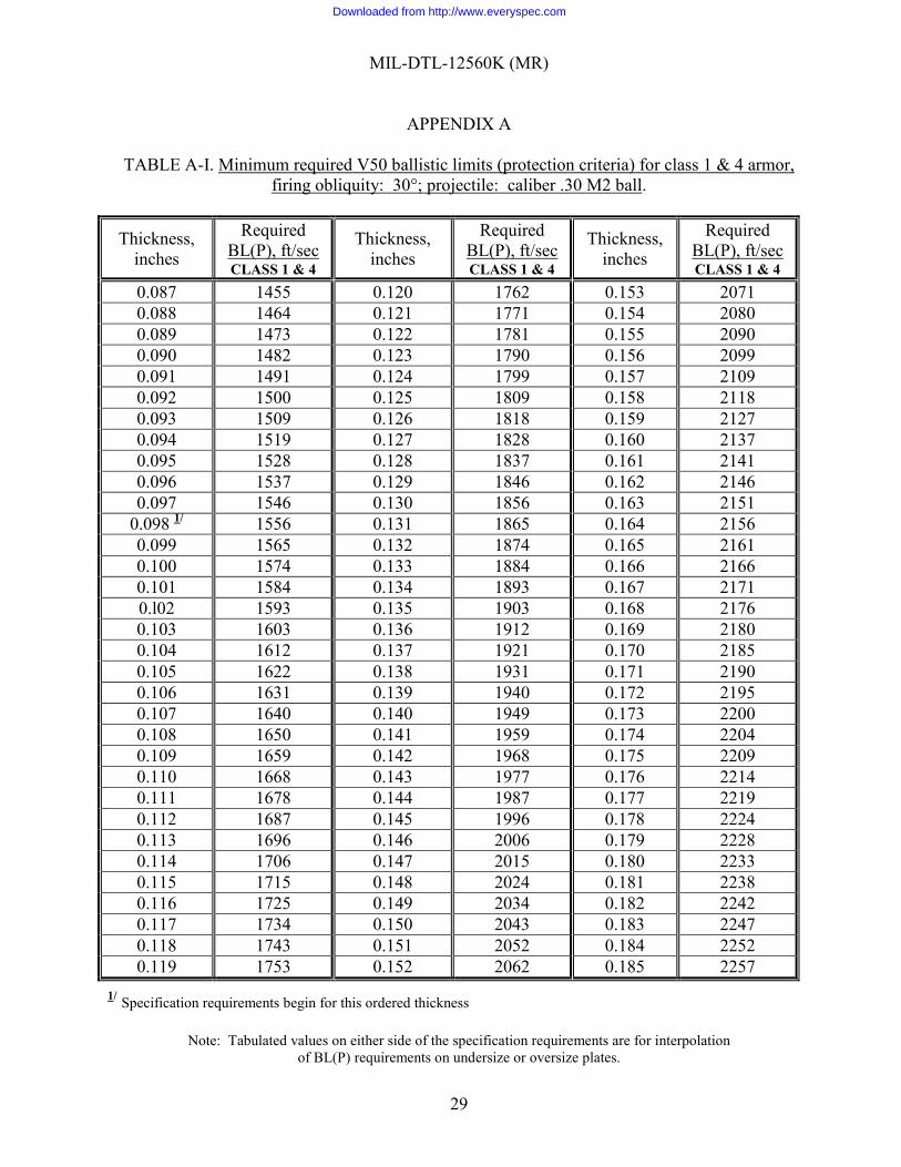
A.4.1 Ballistic tests. V50 ballistic tests shall be performed in accordance with USATECOM TOP 2-2-710, Ballistic Tests of Armor Materials to determine compliance with the requirements of Tables A-I through A-VIII.
A.4.1.1 Plate thickness. Plate thickness as measured by the ballistic test agency shall be used to determine the required ballistic limit of the plate. The required ballistic limit shall be determined by interpolation of the tables in the appendix, if necessary.
A.4.1.2 Lift hole requirement for test plates. A.4.1.2.1 Ballistic acceptance testing plates.
a. Ballistic acceptance test plates for either class 1 or 3 armor which are less that 2.751 inches ordered thicknesses are to be supplied without a lifting hole.
b. Ballistic acceptance test plates for either class 1 or 3 armor which are 2.751 inches through 6.25 inches thick shall be provided with 3-inch diameter lifting holes, one in each of two adjacent sides as shown in Figure A-1.
A.4.1.3 Rejection and retest of ballistic plates.
Downloaded from http://www.everyspec.com
MIL-DTL-12560K (MR)
APPENDIX A
28
A.4.1.3.1 First article tests (rejection). Unless noted otherwise in the contract or order, failure of any one or more of the three first article test plates to meet the minimum ballistic requirements as specified in the appendix to the specification indicates failure of the products and process.
A.4.1.3.2 First article (retests). Resubmission of ballistic retest plates shall not be made until the manufacturer has made the necessary corrections in the processing of the material to the satisfaction of the procuring activity. Three retest plates shall be submitted for first article testing and all three shall pass. A.4.1.3.3 Acceptance tests (rejection). Unless otherwise noted in the contract or order, failure of a test plate to meet the ballistic requirement indicates failure of the lot; however, the final decision shall depend on the outcome of retests, if submitted.
A.4.1.3.4 Acceptance tests (retests). If a test plate representing a lot fails to meet the ballistic requirement, the manufacturer has the following options: Immediately upon notification of the failure:
(1) At manufacturer’s expense submit two additional test plates from the same lot for ballistic retest, or
(2) First re-heat treat (quenching and tempering) the lot and then submit a test plate from the re-treated lot, or
(3) Scrap the lot and submit a plate representing a new lot for acceptance. If the manufacturer chooses any one of these options and the ballistic retest plate (or plates) meet the requirements then the lot represented is acceptable. If he chooses option (1) and one or both the retest plates fail, the manufacturer shall re-heat treat the lot and submit a test plate from the re-treated lot. If this plate fails the lot is rejected. If the manufacturer chooses option (3) and the test plate fails, the manufacturer shall again resort to any one of the three options. A.4.1.4 Disposition of ballistic test plates.
A.4.1.4.1 First article test plates. Upon request of the applicant within 15 days after ballistic testing, first article plates shall be returned “as is” to the applicant, at the applicant’s expense, unless the plates were destroyed in testing.
A.4.1.4.2 Acceptance test plates. Acceptance test plates that comply with the requirements of this specification are considered as part of the lot of steel they represent and ownership of them passes to the Government with the acceptance of that lot. Acceptance test plates that fail to comply with the requirements of this specification are considered as part of the lot they represent and remain the property of the producer just as the rejectable lot does. The failed plates shall be returned, upon request, as in A.4.1.4.1
Downloaded from http://www.everyspec.com
MIL-DTL-12560K (MR)
APPENDIX A
29
TABLE A-I. Minimum required V50 ballistic limits (protection criteria) for class 1 & 4 armor, firing obliquity: 30°; projectile: caliber .30 M2 ball.
Thickness, inches
Required BL(P), ft/sec CLASS 1 & 4
Thickness, inches
Required BL(P), ft/sec CLASS 1 & 4
Thickness, inches
Required BL(P), ft/sec CLASS 1 & 4
0.087 1455 0.120 1762 0.153 2071 0.088 1464 0.121 1771 0.154 2080 0.089 1473 0.122 1781 0.155 2090 0.090 1482 0.123 1790 0.156 2099 0.091 1491 0.124 1799 0.157 2109 0.092 1500 0.125 1809 0.158 2118 0.093 1509 0.126 1818 0.159 2127 0.094 1519 0.127 1828 0.160 2137 0.095 1528 0.128 1837 0.161 2141 0.096 1537 0.129 1846 0.162 2146 0.097 1546 0.130 1856 0.163 2151
0.098 1/ 1556 0.131 1865 0.164 2156 0.099 1565 0.132 1874 0.165 2161 0.100 1574 0.133 1884 0.166 2166 0.101 1584 0.134 1893 0.167 2171 0.l02 1593 0.135 1903 0.168 2176 0.103 1603 0.136 1912 0.169 2180 0.104 1612 0.137 1921 0.170 2185 0.105 1622 0.138 1931 0.171 2190 0.106 1631 0.139 1940 0.172 2195 0.107 1640 0.140 1949 0.173 2200 0.108 1650 0.141 1959 0.174 2204 0.109 1659 0.142 1968 0.175 2209 0.110 1668 0.143 1977 0.176 2214 0.111 1678 0.144 1987 0.177 2219 0.112 1687 0.145 1996 0.178 2224 0.113 1696 0.146 2006 0.179 2228 0.114 1706 0.147 2015 0.180 2233 0.115 1715 0.148 2024 0.181 2238 0.116 1725 0.149 2034 0.182 2242 0.117 1734 0.150 2043 0.183 2247 0.118 1743 0.151 2052 0.184 2252 0.119 1753 0.152 2062 0.185 2257
1/ Specification requirements begin for this ordered thickness
Note: Tabulated values on either side of the specification requirements are for interpolation of BL(P) requirements on undersize or oversize plates.
Downloaded from http://www.everyspec.com
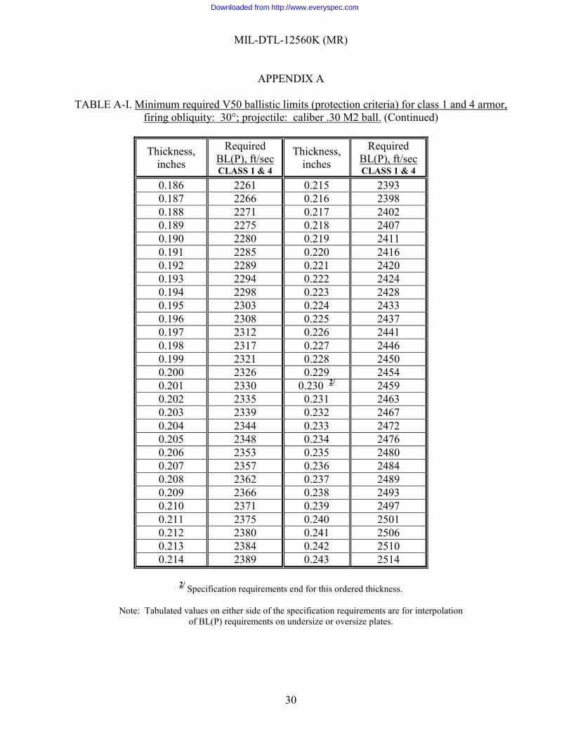
MIL-DTL-12560K (MR)
APPENDIX A
30
TABLE A-I. Minimum required V50 ballistic limits (protection criteria) for class 1 and 4 armor, firing obliquity: 30°; projectile: caliber .30 M2 ball. (Continued)
Thickness, inches
Required BL(P), ft/sec CLASS 1 & 4
Thickness, inches
Required BL(P), ft/sec CLASS 1 & 4
0.186 2261 0.215 2393 0.187 2266 0.216 2398 0.188 2271 0.217 2402 0.189 2275 0.218 2407 0.190 2280 0.219 2411 0.191 2285 0.220 2416 0.192 2289 0.221 2420 0.193 2294 0.222 2424 0.194 2298 0.223 2428 0.195 2303 0.224 2433 0.196 2308 0.225 2437 0.197 2312 0.226 2441 0.198 2317 0.227 2446 0.199 2321 0.228 2450 0.200 2326 0.229 2454 0.201 2330 0.230 2/ 2459 0.202 2335 0.231 2463 0.203 2339 0.232 2467 0.204 2344 0.233 2472 0.205 2348 0.234 2476 0.206 2353 0.235 2480 0.207 2357 0.236 2484 0.208 2362 0.237 2489 0.209 2366 0.238 2493 0.210 2371 0.239 2497 0.211 2375 0.240 2501 0.212 2380 0.241 2506 0.213 2384 0.242 2510 0.214 2389 0.243 2514
2/ Specification requirements end for this ordered thickness.
Note: Tabulated values on either side of the specification requirements are for interpolation
of BL(P) requirements on undersize or oversize plates.
Downloaded from http://www.everyspec.com
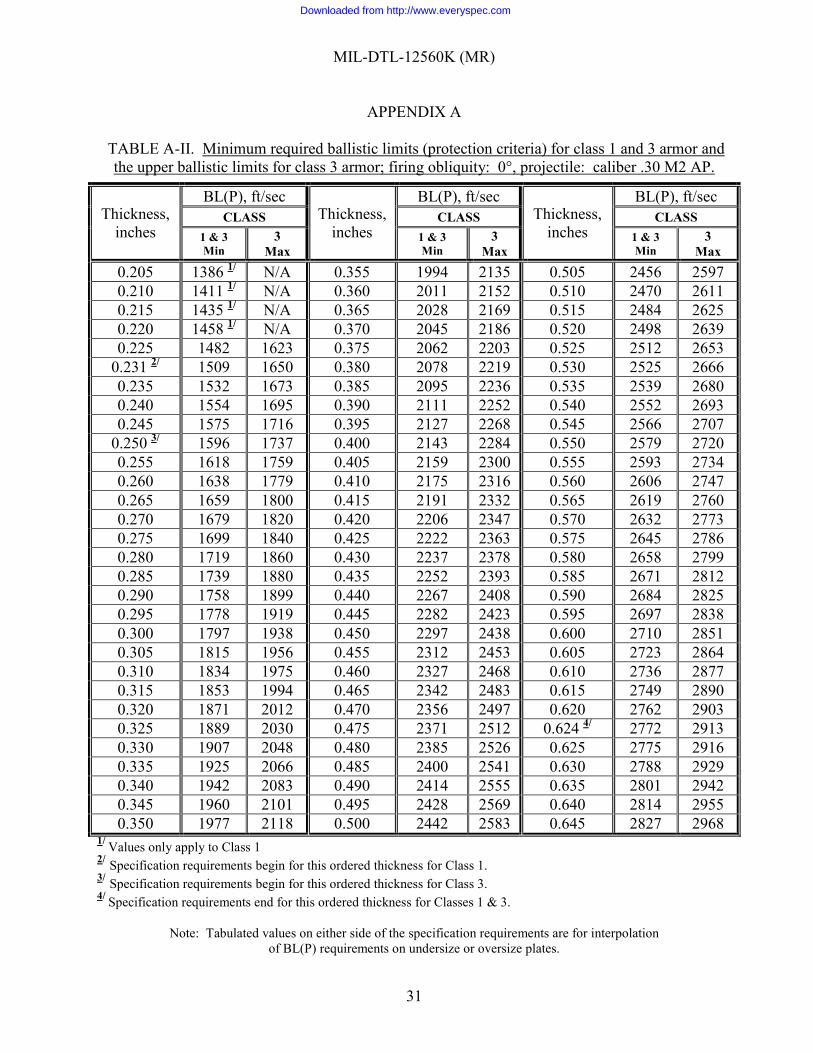
MIL-DTL-12560K (MR)
APPENDIX A
31
TABLE A-II. Minimum required ballistic limits (protection criteria) for class 1 and 3 armor and the upper ballistic limits for class 3 armor; firing obliquity: 0°, projectile: caliber .30 M2 AP.
Thickness, inches
BL(P), ft/sec Thickness,
inches
BL(P), ft/sec Thickness,
inches
BL(P), ft/sec CLASS CLASS CLASS
1 & 3 Min
3 Max
1 & 3 Min
3 Max
1 & 3 Min
3 Max
0.205 1386 1/ N/A 0.355 1994 2135 0.505 2456 2597 0.210 1411 1/ N/A 0.360 2011 2152 0.510 2470 2611 0.215 1435 1/ N/A 0.365 2028 2169 0.515 2484 2625 0.220 1458 1/ N/A 0.370 2045 2186 0.520 2498 2639 0.225 1482 1623 0.375 2062 2203 0.525 2512 2653
0.231 2/ 1509 1650 0.380 2078 2219 0.530 2525 2666 0.235 1532 1673 0.385 2095 2236 0.535 2539 2680 0.240 1554 1695 0.390 2111 2252 0.540 2552 2693 0.245 1575 1716 0.395 2127 2268 0.545 2566 2707
0.250 3/ 1596 1737 0.400 2143 2284 0.550 2579 2720 0.255 1618 1759 0.405 2159 2300 0.555 2593 2734 0.260 1638 1779 0.410 2175 2316 0.560 2606 2747 0.265 1659 1800 0.415 2191 2332 0.565 2619 2760 0.270 1679 1820 0.420 2206 2347 0.570 2632 2773 0.275 1699 1840 0.425 2222 2363 0.575 2645 2786 0.280 1719 1860 0.430 2237 2378 0.580 2658 2799 0.285 1739 1880 0.435 2252 2393 0.585 2671 2812 0.290 1758 1899 0.440 2267 2408 0.590 2684 2825 0.295 1778 1919 0.445 2282 2423 0.595 2697 2838 0.300 1797 1938 0.450 2297 2438 0.600 2710 2851 0.305 1815 1956 0.455 2312 2453 0.605 2723 2864 0.310 1834 1975 0.460 2327 2468 0.610 2736 2877 0.315 1853 1994 0.465 2342 2483 0.615 2749 2890 0.320 1871 2012 0.470 2356 2497 0.620 2762 2903 0.325 1889 2030 0.475 2371 2512 0.624 4/ 2772 2913 0.330 1907 2048 0.480 2385 2526 0.625 2775 2916 0.335 1925 2066 0.485 2400 2541 0.630 2788 2929 0.340 1942 2083 0.490 2414 2555 0.635 2801 2942 0.345 1960 2101 0.495 2428 2569 0.640 2814 2955 0.350 1977 2118 0.500 2442 2583 0.645 2827 2968
1/ Values only apply to Class 1 2/ Specification requirements begin for this ordered thickness for Class 1. 3/ Specification requirements begin for this ordered thickness for Class 3. 4/ Specification requirements end for this ordered thickness for Classes 1 & 3.
Note: Tabulated values on either side of the specification requirements are for interpolation of BL(P) requirements on undersize or oversize plates.
Downloaded from http://www.everyspec.com
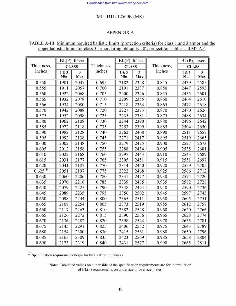
MIL-DTL-12560K (MR)
APPENDIX A
32
TABLE A-III. Minimum required ballistic limits (protection criteria) for class 1 and 3 armor and the upper ballistic limits for class 3 armor; firing obliquity: 0°, projectile: caliber .50 M2 AP.
Thickness, inches
BL(P), ft/sec Thickness,
inches
BL(P), ft/sec Thickness,
inches
BL(P), ft/sec CLASS CLASS CLASS
1 & 3 Min
3 Max
1 & 3 Min
3 Max
1 & 3 Min
3 Max
0.550 1901 2047 0.695 2182 2328 0.845 2439 2585 0.555 1911 2057 0.700 2191 2337 0.850 2447 2593 0.560 1922 2068 0.705 2200 2346 0.855 2455 2601 0.565 1932 2078 0.710 2209 2355 0.860 2464 2610 0.566 1934 2080 0.715 2218 2364 0.865 2472 2618 0.570 1942 2088 0.720 2227 2373 0.870 2480 2626 0.575 1952 2098 0.725 2235 2381 0.875 2488 2634 0.580 1962 2108 0.730 2244 2390 0.880 2496 2642 0.585 1972 2118 0.735 2253 2399 0.885 2504 2650 0.590 1982 2128 0.740 2262 2408 0.890 2511 2657 0.595 1992 2138 0.745 2271 2417 0.895 2519 2665 0.600 2002 2148 0.750 2279 2425 0.900 2527 2673 0.605 2012 2158 0.755 2288 2434 0.905 2535 2681 0.610 2022 2168 0.760 2297 2443 0.910 2543 2689 0.615 2031 2177 0.765 2305 2451 0.915 2551 2697 0.620 2041 2187 0.770 2314 2460 0.920 2559 2705
0.625 1/ 2051 2197 0.775 2322 2468 0.925 2566 2712 0.630 2060 2206 0.780 2331 2477 0.930 2574 2720 0.635 2070 2216 0.785 2339 2485 0.935 2582 2728 0.640 2079 2225 0.790 2348 2494 0.940 2590 2736 0.645 2089 2235 0.795 2356 2502 0.945 2597 2743 0.650 2098 2244 0.800 2365 2511 0.950 2605 2751 0.655 2108 2254 0.805 2373 2519 0.955 2612 2758 0.660 2117 2263 0.810 2382 2528 0.960 2620 2766 0.665 2126 2272 0.815 2390 2536 0.965 2628 2774 0.670 2136 2282 0.820 2398 2544 0.970 2635 2781 0.675 2145 2291 0.825 2406 2552 0.975 2643 2789 0.680 2154 2300 0.830 2415 2561 0.980 2650 2796 0.685 2163 2309 0.835 2423 2569 0.985 2658 2804 0.690 2173 2319 0.840 2431 2577 0.990 2665 2811
1/ Specification requirements begin for this ordered thickness
Note: Tabulated values on either side of the specification requirements are for interpolation of BL(P) requirements on undersize or oversize plates.
Downloaded from http://www.everyspec.com
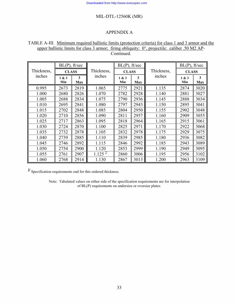
MIL-DTL-12560K (MR)
APPENDIX A
33
TABLE A-III. Minimum required ballistic limits (protection criteria) for class 1 and 3 armor and the upper ballistic limits for class 3 armor; firing obliquity: 0°, projectile: caliber .50 M2 AP-
Continued.
Thickness, inches
BL(P), ft/sec Thickness,
inches
BL(P), ft/sec Thickness,
inches
BL(P), ft/sec CLASS CLASS CLASS
1 & 3 Min
3 Max
1 & 3 Min
3 Max
1 & 3 Min
3 Max
0.995 2673 2819 1.065 2775 2921 1.135 2874 3020 1.000 2680 2826 1.070 2782 2928 1.140 2881 3027 1.005 2688 2834 1.075 2790 2936 1.145 2888 3034 1.010 2695 2841 1.080 2797 2943 1.150 2895 3041 1.015 2702 2848 1.085 2804 2950 1.155 2902 3048 1.020 2710 2856 1.090 2811 2957 1.160 2909 3055 1.025 2717 2863 1.095 2818 2964 1.165 2915 3061 1.030 2724 2870 1.100 2825 2971 1.170 2922 3068 1.035 2732 2878 1.105 2832 2978 1.175 2929 3075 1.040 2739 2885 1.110 2839 2985 1.180 2936 3082 1.045 2746 2892 1.115 2846 2992 1.185 2943 3089 1.050 2754 2900 1.120 2853 2999 1.190 2949 3095 1.055 2761 2907 1.125 2/ 2860 3006 1.195 2956 3102 1.060 2768 2914 1.130 2867 3013 1.200 2963 3109
2/ Specification requirements end for this ordered thickness.
Note: Tabulated values on either side of the specification requirements are for interpolation
of BL(P) requirements on undersize or oversize plates.
Downloaded from http://www.everyspec.com
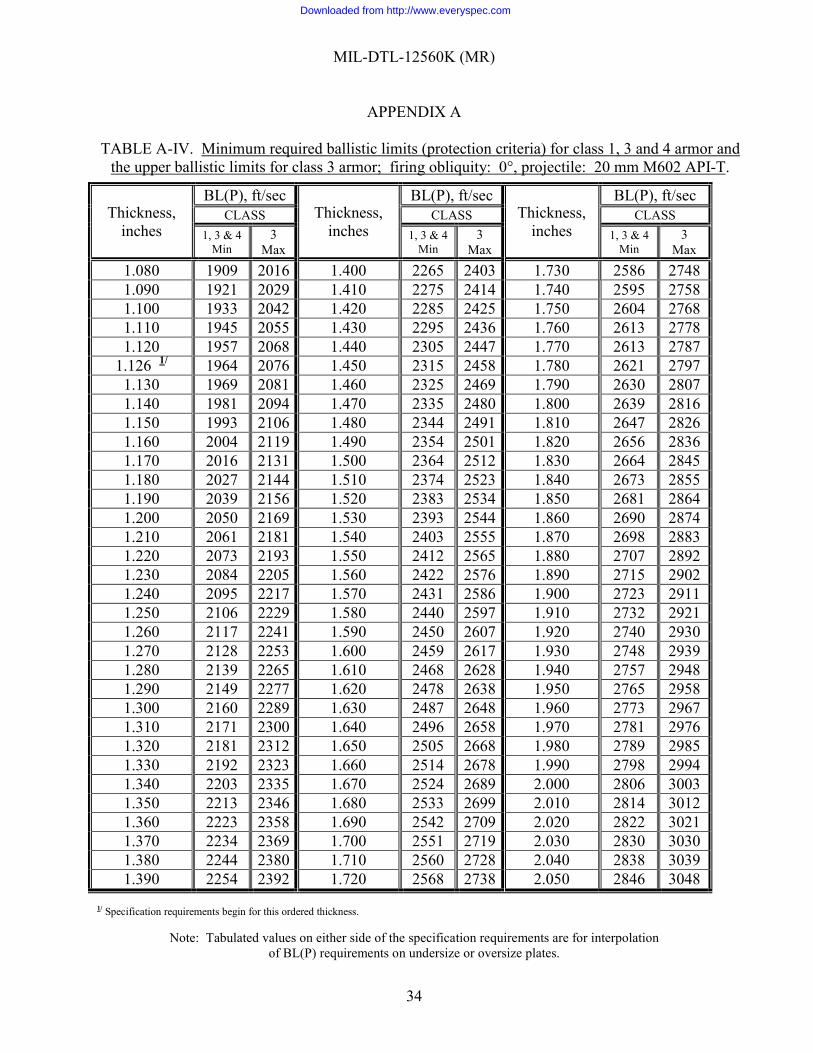
MIL-DTL-12560K (MR)
APPENDIX A
34
TABLE A-IV. Minimum required ballistic limits (protection criteria) for class 1, 3 and 4 armor and the upper ballistic limits for class 3 armor; firing obliquity: 0°, projectile: 20 mm M602 API-T.
Thickness, inches
BL(P), ft/sec Thickness,
inches
BL(P), ft/sec Thickness,
inches
BL(P), ft/sec CLASS CLASS CLASS
1, 3 & 4 Min
3 Max
1, 3 & 4 Min
3 Max
1, 3 & 4 Min
3 Max
1.080 1909 2016 1.400 2265 2403 1.730 2586 2748 1.090 1921 2029 1.410 2275 2414 1.740 2595 2758 1.100 1933 2042 1.420 2285 2425 1.750 2604 2768 1.110 1945 2055 1.430 2295 2436 1.760 2613 2778 1.120 1957 2068 1.440 2305 2447 1.770 2613 2787
1.126 1/ 1964 2076 1.450 2315 2458 1.780 2621 2797 1.130 1969 2081 1.460 2325 2469 1.790 2630 2807 1.140 1981 2094 1.470 2335 2480 1.800 2639 2816 1.150 1993 2106 1.480 2344 2491 1.810 2647 2826 1.160 2004 2119 1.490 2354 2501 1.820 2656 2836 1.170 2016 2131 1.500 2364 2512 1.830 2664 2845 1.180 2027 2144 1.510 2374 2523 1.840 2673 2855 1.190 2039 2156 1.520 2383 2534 1.850 2681 2864 1.200 2050 2169 1.530 2393 2544 1.860 2690 2874 1.210 2061 2181 1.540 2403 2555 1.870 2698 2883 1.220 2073 2193 1.550 2412 2565 1.880 2707 2892 1.230 2084 2205 1.560 2422 2576 1.890 2715 2902 1.240 2095 2217 1.570 2431 2586 1.900 2723 2911 1.250 2106 2229 1.580 2440 2597 1.910 2732 2921 1.260 2117 2241 1.590 2450 2607 1.920 2740 2930 1.270 2128 2253 1.600 2459 2617 1.930 2748 2939 1.280 2139 2265 1.610 2468 2628 1.940 2757 2948 1.290 2149 2277 1.620 2478 2638 1.950 2765 2958 1.300 2160 2289 1.630 2487 2648 1.960 2773 2967 1.310 2171 2300 1.640 2496 2658 1.970 2781 2976 1.320 2181 2312 1.650 2505 2668 1.980 2789 2985 1.330 2192 2323 1.660 2514 2678 1.990 2798 2994 1.340 2203 2335 1.670 2524 2689 2.000 2806 3003 1.350 2213 2346 1.680 2533 2699 2.010 2814 3012 1.360 2223 2358 1.690 2542 2709 2.020 2822 3021 1.370 2234 2369 1.700 2551 2719 2.030 2830 3030 1.380 2244 2380 1.710 2560 2728 2.040 2838 3039 1.390 2254 2392 1.720 2568 2738 2.050 2846 3048
1/ Specification requirements begin for this ordered thickness.
Note: Tabulated values on either side of the specification requirements are for interpolation of BL(P) requirements on undersize or oversize plates.
Downloaded from http://www.everyspec.com
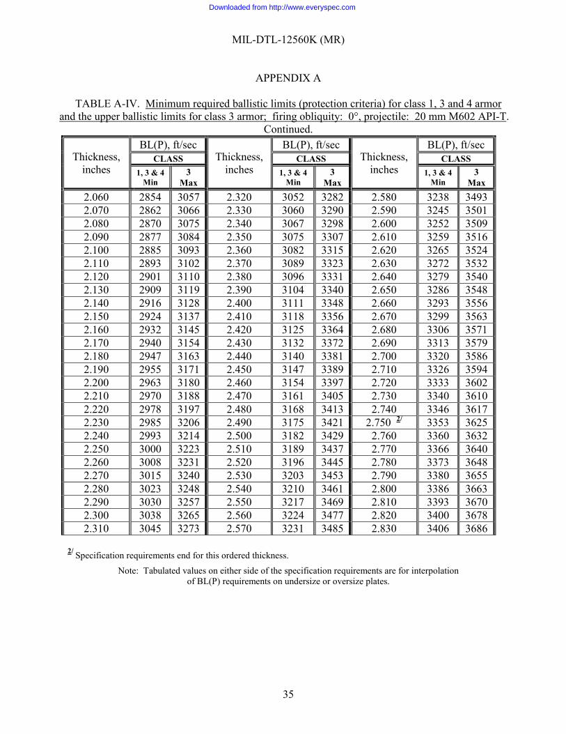
MIL-DTL-12560K (MR)
APPENDIX A
35
TABLE A-IV. Minimum required ballistic limits (protection criteria) for class 1, 3 and 4 armor and the upper ballistic limits for class 3 armor; firing obliquity: 0°, projectile: 20 mm M602 API-T.
Continued.
Thickness, inches
BL(P), ft/sec Thickness,
inches
BL(P), ft/sec Thickness,
inches
BL(P), ft/sec CLASS CLASS CLASS
1, 3 & 4 Min
3 Max
1, 3 & 4 Min
3 Max
1, 3 & 4 Min
3 Max
2.060 2854 3057 2.320 3052 3282 2.580 3238 3493 2.070 2862 3066 2.330 3060 3290 2.590 3245 3501 2.080 2870 3075 2.340 3067 3298 2.600 3252 3509 2.090 2877 3084 2.350 3075 3307 2.610 3259 3516 2.100 2885 3093 2.360 3082 3315 2.620 3265 3524 2.110 2893 3102 2.370 3089 3323 2.630 3272 3532 2.120 2901 3110 2.380 3096 3331 2.640 3279 3540 2.130 2909 3119 2.390 3104 3340 2.650 3286 3548 2.140 2916 3128 2.400 3111 3348 2.660 3293 3556 2.150 2924 3137 2.410 3118 3356 2.670 3299 3563 2.160 2932 3145 2.420 3125 3364 2.680 3306 3571 2.170 2940 3154 2.430 3132 3372 2.690 3313 3579 2.180 2947 3163 2.440 3140 3381 2.700 3320 3586 2.190 2955 3171 2.450 3147 3389 2.710 3326 3594 2.200 2963 3180 2.460 3154 3397 2.720 3333 3602 2.210 2970 3188 2.470 3161 3405 2.730 3340 3610 2.220 2978 3197 2.480 3168 3413 2.740 3346 3617 2.230 2985 3206 2.490 3175 3421 2.750 2/ 3353 3625 2.240 2993 3214 2.500 3182 3429 2.760 3360 3632 2.250 3000 3223 2.510 3189 3437 2.770 3366 3640 2.260 3008 3231 2.520 3196 3445 2.780 3373 3648 2.270 3015 3240 2.530 3203 3453 2.790 3380 3655 2.280 3023 3248 2.540 3210 3461 2.800 3386 3663 2.290 3030 3257 2.550 3217 3469 2.810 3393 3670 2.300 3038 3265 2.560 3224 3477 2.820 3400 3678 2.310 3045 3273 2.570 3231 3485 2.830 3406 3686
2/ Specification requirements end for this ordered thickness.
Note: Tabulated values on either side of the specification requirements are for interpolation of BL(P) requirements on undersize or oversize plates.
Downloaded from http://www.everyspec.com
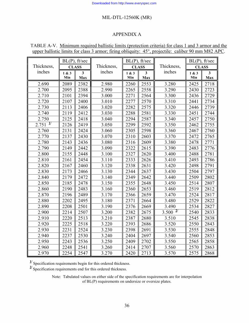
MIL-DTL-12560K (MR)
APPENDIX A
36
TABLE A-V. Minimum required ballistic limits (protection criteria) for class 1 and 3 armor and the upper ballistic limits for class 3 armor; firing obliquity: 45°, projectile: caliber 90 mm M82 APC.
Thickness, inches
BL(P), ft/sec Thickness,
inches
BL(P), ft/sec Thickness,
inches
BL(P), ft/sec CLASS CLASS CLASS
1 & 3 Min
3 Max
1 & 3 Min
3 Max
1 & 3 Min
3 Max
2.690 2089 2382 2.980 2260 2553 3.280 2425 2718 2.700 2095 2388 2.990 2265 2558 3.290 2430 2723 2.710 2101 2394 3.000 2271 2564 3.300 2436 2729 2.720 2107 2400 3.010 2277 2570 3.310 2441 2734 2.730 2113 2406 3.020 2282 2575 3.320 2446 2739 2.740 2119 2412 3.030 2288 2581 3.330 2451 2744 2.750 2125 2418 3.040 2294 2587 3.340 2457 2750
2.751 1/ 2126 2419 3.050 2299 2592 3.350 2462 2755 2.760 2131 2424 3.060 2305 2598 3.360 2467 2760 2.770 2137 2430 3.070 2310 2603 3.370 2472 2765 2.780 2143 2436 3.080 2316 2609 3.380 2478 2771 2.790 2149 2442 3.090 2322 2615 3.390 2483 2776 2.800 2155 2448 3.100 2327 2620 3.400 2488 2781 2.810 2161 2454 3.110 2333 2626 3.410 2493 2786 2.820 2167 2460 3.120 2338 2631 3.420 2498 2791 2.830 2173 2466 3.130 2344 2637 3.430 2504 2797 2.840 2179 2472 3.140 2349 2642 3.440 2509 2802 2.850 2185 2478 3.150 2355 2648 3.450 2514 2807 2.860 2190 2483 3.160 2360 2653 3.460 2519 2812 2.870 2196 2489 3.170 2366 2659 3.470 2524 2817 2.880 2202 2495 3.180 2371 2664 3.480 2529 2822 2.890 2208 2501 3.190 2376 2669 3.490 2534 2827 2.900 2214 2507 3.200 2382 2675 3.500 2/ 2540 2833 2.910 2220 2513 3.210 2387 2680 3.510 2545 2838 2.920 2225 2518 3.220 2393 2686 3.520 2550 2843 2.930 2231 2524 3.230 2398 2691 3.530 2555 2848 2.940 2237 2530 3.240 2404 2697 3.540 2560 2853 2.950 2243 2536 3.250 2409 2702 3.550 2565 2858 2.960 2248 2541 3.260 2414 2707 3.560 2570 2863 2.970 2254 2547 3.270 2420 2713 3.570 2575 2868
1/ Specification requirements begin for this ordered thickness. 2/ Specification requirements end for this ordered thickness.
Note: Tabulated values on either side of the specification requirements are for interpolation of BL(P) requirements on undersize or oversize plates.
Downloaded from http://www.everyspec.com
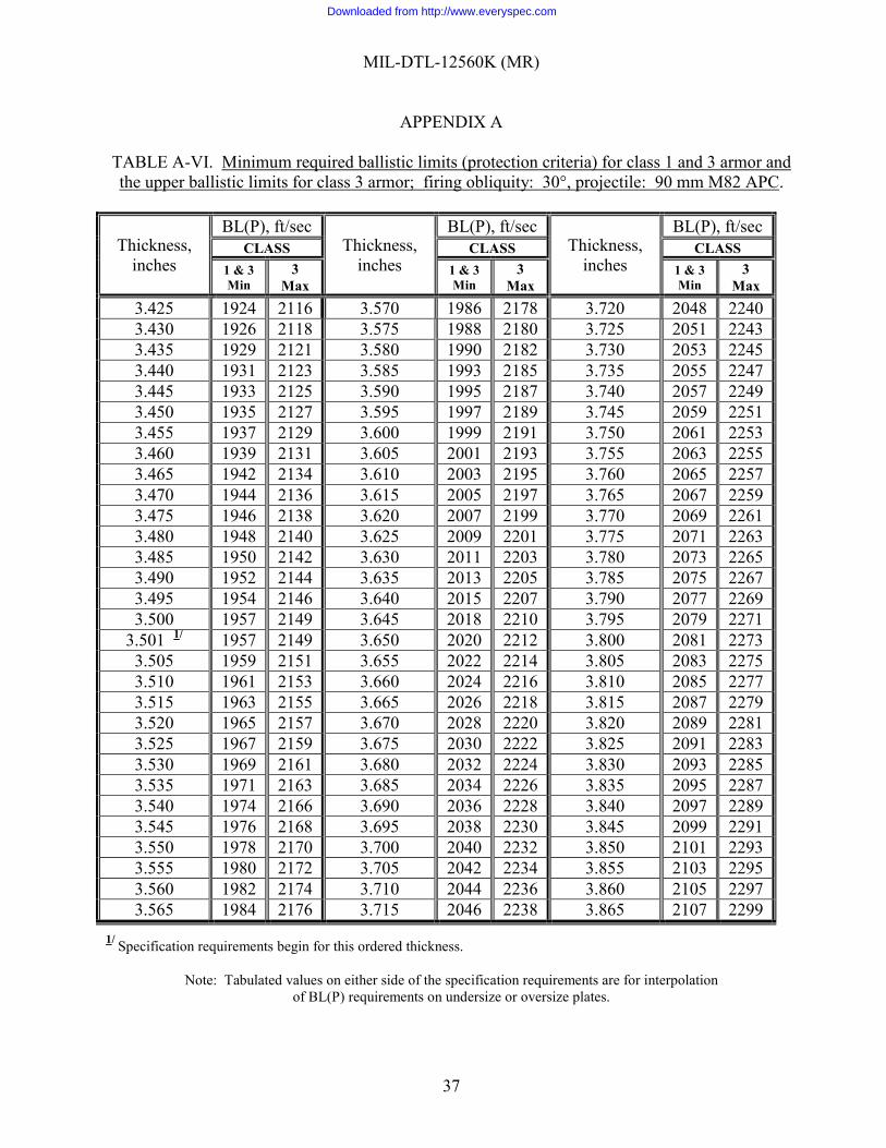
MIL-DTL-12560K (MR)
APPENDIX A
37
TABLE A-VI. Minimum required ballistic limits (protection criteria) for class 1 and 3 armor and the upper ballistic limits for class 3 armor; firing obliquity: 30°, projectile: 90 mm M82 APC.
Thickness, inches
BL(P), ft/sec Thickness,
inches
BL(P), ft/sec Thickness,
inches
BL(P), ft/sec CLASS CLASS CLASS
1 & 3 Min
3 Max
1 & 3 Min
3 Max
1 & 3 Min
3 Max
3.425 1924 2116 3.570 1986 2178 3.720 2048 2240 3.430 1926 2118 3.575 1988 2180 3.725 2051 2243 3.435 1929 2121 3.580 1990 2182 3.730 2053 2245 3.440 1931 2123 3.585 1993 2185 3.735 2055 2247 3.445 1933 2125 3.590 1995 2187 3.740 2057 2249 3.450 1935 2127 3.595 1997 2189 3.745 2059 2251 3.455 1937 2129 3.600 1999 2191 3.750 2061 2253 3.460 1939 2131 3.605 2001 2193 3.755 2063 2255 3.465 1942 2134 3.610 2003 2195 3.760 2065 2257 3.470 1944 2136 3.615 2005 2197 3.765 2067 2259 3.475 1946 2138 3.620 2007 2199 3.770 2069 2261 3.480 1948 2140 3.625 2009 2201 3.775 2071 2263 3.485 1950 2142 3.630 2011 2203 3.780 2073 2265 3.490 1952 2144 3.635 2013 2205 3.785 2075 2267 3.495 1954 2146 3.640 2015 2207 3.790 2077 2269 3.500 1957 2149 3.645 2018 2210 3.795 2079 2271
3.501 1/ 1957 2149 3.650 2020 2212 3.800 2081 2273 3.505 1959 2151 3.655 2022 2214 3.805 2083 2275 3.510 1961 2153 3.660 2024 2216 3.810 2085 2277 3.515 1963 2155 3.665 2026 2218 3.815 2087 2279 3.520 1965 2157 3.670 2028 2220 3.820 2089 2281 3.525 1967 2159 3.675 2030 2222 3.825 2091 2283 3.530 1969 2161 3.680 2032 2224 3.830 2093 2285 3.535 1971 2163 3.685 2034 2226 3.835 2095 2287 3.540 1974 2166 3.690 2036 2228 3.840 2097 2289 3.545 1976 2168 3.695 2038 2230 3.845 2099 2291 3.550 1978 2170 3.700 2040 2232 3.850 2101 2293 3.555 1980 2172 3.705 2042 2234 3.855 2103 2295 3.560 1982 2174 3.710 2044 2236 3.860 2105 2297 3.565 1984 2176 3.715 2046 2238 3.865 2107 2299
1/ Specification requirements begin for this ordered thickness.
Note: Tabulated values on either side of the specification requirements are for interpolation of BL(P) requirements on undersize or oversize plates.
Downloaded from http://www.everyspec.com
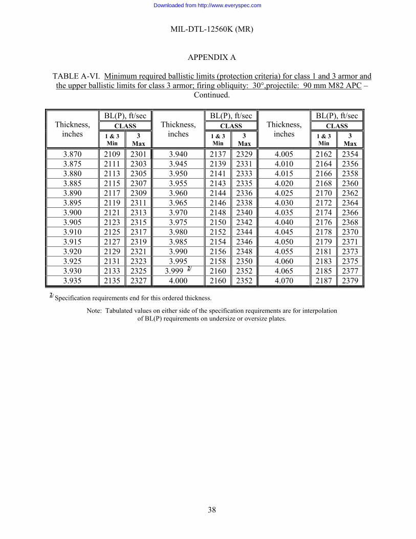
MIL-DTL-12560K (MR)
APPENDIX A
38
TABLE A-VI. Minimum required ballistic limits (protection criteria) for class 1 and 3 armor and the upper ballistic limits for class 3 armor; firing obliquity: 30°,projectile: 90 mm M82 APC –
Continued.
Thickness, inches
BL(P), ft/sec Thickness,
inches
BL(P), ft/sec Thickness,
inches
BL(P), ft/sec CLASS CLASS CLASS
1 & 3 Min
3 Max
1 & 3 Min
3 Max
1 & 3 Min
3 Max
3.870 2109 2301 3.940 2137 2329 4.005 2162 2354 3.875 2111 2303 3.945 2139 2331 4.010 2164 2356 3.880 2113 2305 3.950 2141 2333 4.015 2166 2358 3.885 2115 2307 3.955 2143 2335 4.020 2168 2360 3.890 2117 2309 3.960 2144 2336 4.025 2170 2362 3.895 2119 2311 3.965 2146 2338 4.030 2172 2364 3.900 2121 2313 3.970 2148 2340 4.035 2174 2366 3.905 2123 2315 3.975 2150 2342 4.040 2176 2368 3.910 2125 2317 3.980 2152 2344 4.045 2178 2370 3.915 2127 2319 3.985 2154 2346 4.050 2179 2371 3.920 2129 2321 3.990 2156 2348 4.055 2181 2373 3.925 2131 2323 3.995 2158 2350 4.060 2183 2375 3.930 2133 2325 3.999 2/ 2160 2352 4.065 2185 2377 3.935 2135 2327 4.000 2160 2352 4.070 2187 2379
2/ Specification requirements end for this ordered thickness.
Note: Tabulated values on either side of the specification requirements are for interpolation of BL(P) requirements on undersize or oversize plates.
Downloaded from http://www.everyspec.com
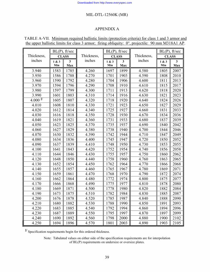
MIL-DTL-12560K (MR)
APPENDIX A
39
TABLE A-VII. Minimum required ballistic limits (protection criteria) for class 1 and 3 armor and the upper ballistic limits for class 3 armor; firing obliquity: 0°, projectile: 90 mm M318A1 AP.
Thickness, inches
BL(P), ft/sec Thickness,
inches
BL(P), ft/sec Thickness,
inches
BL(P), ft/sec CLASS CLASS CLASS
1 & 3 Min
3 Max
1 & 3 Min
3 Max
1 & 3 Min
3 Max
3.940 1583 1785 4.260 1697 1899 4.580 1805 2007 3.950 1586 1788 4.270 1701 1903 4.590 1808 2010 3.960 1590 1792 4.280 1704 1906 4.600 1811 2013 3.970 1594 1796 4.290 1708 1910 4.610 1815 2017 3.980 1597 1799 4.300 1711 1913 4.620 1818 2020 3.990 1601 1803 4.310 1714 1916 4.630 1821 2023
4.000 1/ 1605 1807 4.320 1718 1920 4.640 1824 2026 4.010 1608 1810 4.330 1721 1923 4.650 1827 2029 4.020 1612 1814 4.340 1725 1927 4.660 1831 2033 4.030 1616 1818 4.350 1728 1930 4.670 1834 2036 4.040 1619 1821 4.360 1731 1933 4.680 1837 2039 4.050 1623 1825 4.370 1735 1937 4.690 1840 2042 4.060 1627 1829 4.380 1738 1940 4.700 1844 2046 4.070 1630 1832 4.390 1742 1944 4.710 1847 2049 4.080 1634 1836 4.400 1745 1947 4.720 1850 2052 4.090 1637 1839 4.410 1748 1950 4.730 1853 2055 4.100 1641 1843 4.420 1752 1954 4.740 1856 2058 4.110 1644 1846 4.430 1755 1957 4.750 1860 2062 4.120 1648 1850 4.440 1758 1960 4.760 1863 2065 4.130 1652 1854 4.450 1762 1964 4.770 1866 2068 4.140 1655 1857 4.460 1765 1967 4.780 1869 2071 4.150 1659 1861 4.470 1768 1970 4.790 1872 2074 4.160 1662 1864 4.480 1772 1974 4.800 1875 2077 4.170 1666 1868 4.490 1775 1977 4.810 1878 2080 4.180 1669 1871 4.500 1778 1980 4.820 1882 2084 4.190 1673 1875 4.510 1782 1984 4.830 1885 2087 4.200 1676 1878 4.520 1785 1987 4.840 1888 2090 4.210 1680 1882 4.530 1788 1990 4.850 1891 2093 4.220 1683 1885 4.540 1792 1994 4.860 1894 2096 4.230 1687 1889 4.550 1795 1997 4.870 1897 2099 4.240 1690 1892 4.560 1798 2000 4.880 1900 2102 4.250 1694 1896 4.570 1801 2003 4.890 1903 2105
1/ Specification requirements begin for this ordered thickness.
Note: Tabulated values on either side of the specification requirements are for interpolation of BL(P) requirements on undersize or oversize plates.
Downloaded from http://www.everyspec.com
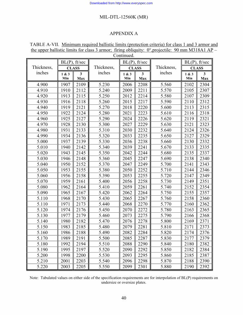
MIL-DTL-12560K (MR)
APPENDIX A
40
TABLE A-VII. Minimum required ballistic limits (protection criteria) for class 1 and 3 armor and the upper ballistic limits for class 3 armor; firing obliquity: 0°,projectile: 90 mm M318A1 AP –
Continued.
Thickness, inches
BL(P), ft/sec Thickness,
inches
BL(P), ft/sec Thickness,
inches
BL(P), ft/sec CLASS CLASS CLASS
1 & 3 Min
3 Max
1 & 3 Min
3 Max
1 & 3 Min
3 Max
4.900 1907 2109 5.230 2006 2208 5.560 2102 2304 4.910 1910 2112 5.240 2009 2211 5.570 2105 2307 4.920 1913 2115 5.250 2012 2214 5.580 2107 2309 4.930 1916 2118 5.260 2015 2217 5.590 2110 2312 4.940 1919 2121 5.270 2018 2220 5.600 2113 2315 4.950 1922 2124 5.280 2021 2223 5.610 2116 2318 4.960 1925 2127 5.290 2024 2226 5.620 2119 2321 4.970 1928 2130 5.300 2027 2229 5.630 2121 2323 4.980 1931 2133 5.310 2030 2232 5.640 2124 2326 4.990 1934 2136 5.320 2033 2235 5.650 2127 2329 5.000 1937 2139 5.330 2036 2238 5.660 2130 2332 5.010 1940 2142 5.340 2039 2241 5.670 2133 2335 5.020 1943 2145 5.350 2042 2244 5.680 2135 2337 5.030 1946 2148 5.360 2045 2247 5.690 2138 2340 5.040 1950 2152 5.370 2047 2249 5.700 2141 2343 5.050 1953 2155 5.380 2050 2252 5.710 2144 2346 5.060 1956 2158 5.390 2053 2255 5.720 2147 2349 5.070 1959 2161 5.400 2056 2258 5.730 2149 2351 5.080 1962 2164 5.410 2059 2261 5.740 2152 2354 5.090 1965 2167 5.420 2062 2264 5.750 2155 2357 5.110 1968 2170 5.430 2065 2267 5.760 2158 2360 5.110 1971 2173 5.440 2068 2270 5.770 2160 2362 5.120 1974 2176 5.450 2070 2272 5.780 2163 2365 5.130 1977 2179 5.460 2073 2275 5.790 2166 2368 5.140 1980 2182 5.470 2076 2278 5.800 2169 2371 5.150 1983 2185 5.480 2079 2281 5.810 2171 2373 5.160 1986 2188 5.490 2082 2284 5.820 2174 2376 5.170 1989 2191 5.500 2085 2287 5.830 2177 2379 5.180 1992 2194 5.510 2088 2290 5.840 2180 2382 5.190 1995 2197 5.520 2090 2292 5.850 2182 2384 5.200 1998 2200 5.530 2093 2295 5.860 2185 2387 5.210 2001 2203 5.540 2096 2298 5.870 2188 2390 5.220 2003 2205 5.550 2099 2301 5.880 2190 2392
Note: Tabulated values on either side of the specification requirements are for interpolation of BL(P) requirements on
undersize or oversize plates.
Downloaded from http://www.everyspec.com
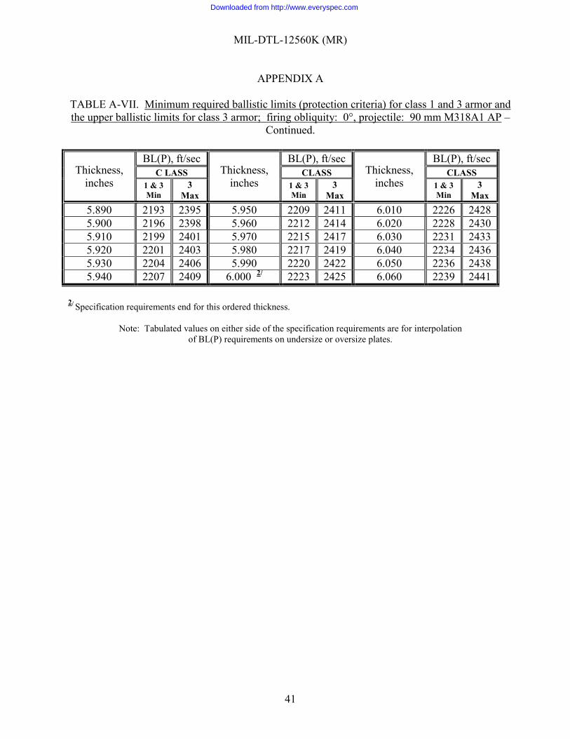
MIL-DTL-12560K (MR)
APPENDIX A
41
TABLE A-VII. Minimum required ballistic limits (protection criteria) for class 1 and 3 armor and the upper ballistic limits for class 3 armor; firing obliquity: 0°, projectile: 90 mm M318A1 AP –
Continued.
Thickness, inches
BL(P), ft/sec Thickness,
inches
BL(P), ft/sec Thickness,
inches
BL(P), ft/sec C LASS CLASS CLASS
1 & 3 Min
3 Max
1 & 3 Min
3 Max
1 & 3 Min
3 Max
5.890 2193 2395 5.950 2209 2411 6.010 2226 2428 5.900 2196 2398 5.960 2212 2414 6.020 2228 2430 5.910 2199 2401 5.970 2215 2417 6.030 2231 2433 5.920 2201 2403 5.980 2217 2419 6.040 2234 2436 5.930 2204 2406 5.990 2220 2422 6.050 2236 2438 5.940 2207 2409 6.000 2/ 2223 2425 6.060 2239 2441
2/ Specification requirements end for this ordered thickness.
Note: Tabulated values on either side of the specification requirements are for interpolation of BL(P) requirements on undersize or oversize plates.
Downloaded from http://www.everyspec.com

MIL-DTL-12560K (MR)
APPENDIX A
42
TABLE A-VIII. Minimum required ballistic limits (protection criteria) for class 2 armor, firing obliquity: 0°, projectile: caliber .30 FSP.
Thickness,
inches Required
BL(P), ft/sec Thickness,
inches Required
BL(P), ft/sec Thickness,
inches Required
BL(P), ft/sec
0.087 1102 0.120 1489 0.153 1875 0.088 1114 0.121 1500 0.154 1887 0.089 1125 0.122 1512 0.155 1899 0.090 1137 0.123 1524 0.156 1911 0.091 1149 0.124 1536 0.157 1922 0.092 1160 0.125 1547 0.158 1934 0.093 1172 0.126 1559 0.159 1946 0.094 1184 0.127 1571 0.160 1958 0.095 1196 0.128 1582 0.161 1969 0.096 1207 0.129 1594 0.162 1981 0.097 1219 0.130 1606 0.163 1993
0.098 1/ 1231 0.131 1618 0.164 2004 0.099 1242 0.132 1629 0.165 2016 0.100 1254 0.133 1641 0.166 2028 0.101 1266 0.134 1653 0.167 2040 0.l02 1278 0.135 1664 0.168 2051 0.103 1289 0.136 1676 0.169 2063 0.104 1301 0.137 1688 0.170 2075 0.105 1313 0.138 1700 0.171 2086 0.106 1325 0.139 1711 0.172 2098 0.107 1336 0.140 1723 0.173 2110 0.108 1348 0.141 1735 0.174 2122 0.109 1360 0.142 1747 0.175 2133 0.110 1371 0.143 1758 0.176 2145 0.111 1383 0.144 1770 0.177 2157 0.112 1395 0.145 1782 0.178 2169 0.113 1407 0.146 1793 0.179 2180 0.114 1418 0.147 1805 0.180 2192 0.115 1430 0.148 1817 0.181 2204 0.116 1442 0.149 1829 0.182 2215 0.117 1453 0.150 1840 0.183 2227 0.118 1465 0.151 1852 0.184 2239 0.119 1477 0.152 1864 0.185 2251
1/ Specification requirements begin for this ordered thickness
Note: Tabulated values on either side of the specification requirements are for interpolation of BL(P) requirements on undersize or oversize plates.
Downloaded from http://www.everyspec.com
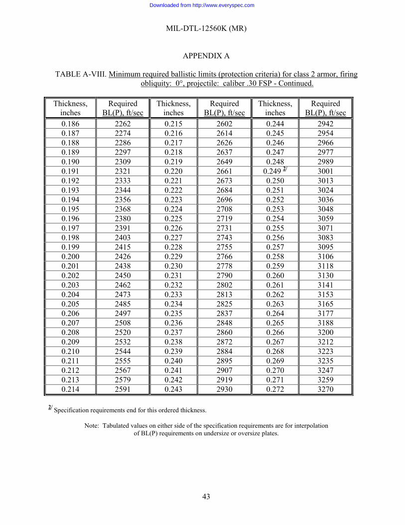
MIL-DTL-12560K (MR)
APPENDIX A
43
TABLE A-VIII. Minimum required ballistic limits (protection criteria) for class 2 armor, firing obliquity: 0°, projectile: caliber .30 FSP - Continued.
Thickness,
inches Required
BL(P), ft/sec Thickness,
inches Required
BL(P), ft/sec Thickness,
inches Required
BL(P), ft/sec
0.186 2262 0.215 2602 0.244 2942 0.187 2274 0.216 2614 0.245 2954 0.188 2286 0.217 2626 0.246 2966 0.189 2297 0.218 2637 0.247 2977 0.190 2309 0.219 2649 0.248 2989 0.191 2321 0.220 2661 0.249 2/ 3001 0.192 2333 0.221 2673 0.250 3013 0.193 2344 0.222 2684 0.251 3024 0.194 2356 0.223 2696 0.252 3036 0.195 2368 0.224 2708 0.253 3048 0.196 2380 0.225 2719 0.254 3059 0.197 2391 0.226 2731 0.255 3071 0.198 2403 0.227 2743 0.256 3083 0.199 2415 0.228 2755 0.257 3095 0.200 2426 0.229 2766 0.258 3106 0.201 2438 0.230 2778 0.259 3118 0.202 2450 0.231 2790 0.260 3130 0.203 2462 0.232 2802 0.261 3141 0.204 2473 0.233 2813 0.262 3153 0.205 2485 0.234 2825 0.263 3165 0.206 2497 0.235 2837 0.264 3177 0.207 2508 0.236 2848 0.265 3188 0.208 2520 0.237 2860 0.266 3200 0.209 2532 0.238 2872 0.267 3212 0.210 2544 0.239 2884 0.268 3223 0.211 2555 0.240 2895 0.269 3235 0.212 2567 0.241 2907 0.270 3247 0.213 2579 0.242 2919 0.271 3259 0.214 2591 0.243 2930 0.272 3270
2/ Specification requirements end for this ordered thickness.
Note: Tabulated values on either side of the specification requirements are for interpolation
of BL(P) requirements on undersize or oversize plates.
Downloaded from http://www.everyspec.com
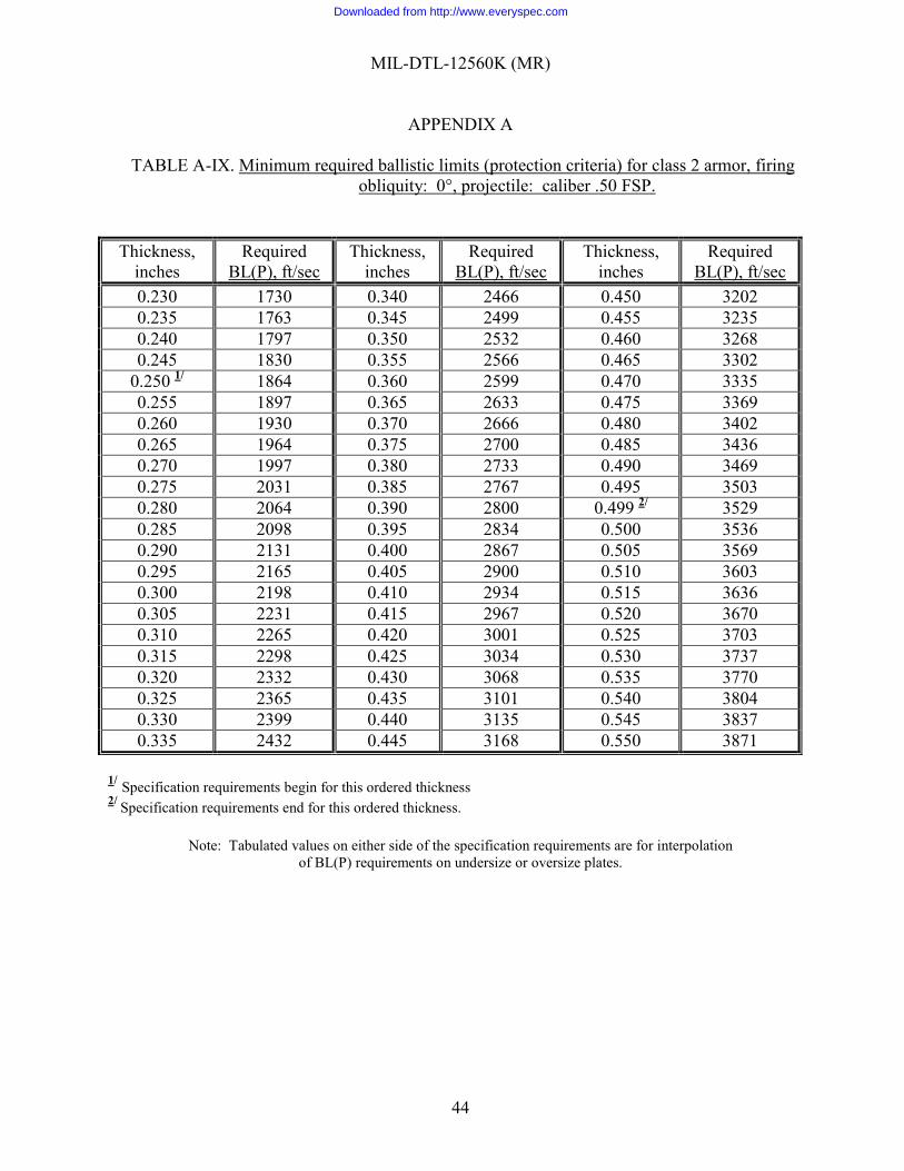
MIL-DTL-12560K (MR)
APPENDIX A
44
TABLE A-IX. Minimum required ballistic limits (protection criteria) for class 2 armor, firing obliquity: 0°, projectile: caliber .50 FSP.
Thickness, inches
Required BL(P), ft/sec
Thickness, inches
Required BL(P), ft/sec
Thickness, inches
Required BL(P), ft/sec
0.230 1730 0.340 2466 0.450 3202 0.235 1763 0.345 2499 0.455 3235 0.240 1797 0.350 2532 0.460 3268 0.245 1830 0.355 2566 0.465 3302
0.250 1/ 1864 0.360 2599 0.470 3335 0.255 1897 0.365 2633 0.475 3369 0.260 1930 0.370 2666 0.480 3402 0.265 1964 0.375 2700 0.485 3436 0.270 1997 0.380 2733 0.490 3469 0.275 2031 0.385 2767 0.495 3503 0.280 2064 0.390 2800 0.499 2/ 3529 0.285 2098 0.395 2834 0.500 3536 0.290 2131 0.400 2867 0.505 3569 0.295 2165 0.405 2900 0.510 3603 0.300 2198 0.410 2934 0.515 3636 0.305 2231 0.415 2967 0.520 3670 0.310 2265 0.420 3001 0.525 3703 0.315 2298 0.425 3034 0.530 3737 0.320 2332 0.430 3068 0.535 3770 0.325 2365 0.435 3101 0.540 3804 0.330 2399 0.440 3135 0.545 3837 0.335 2432 0.445 3168 0.550 3871
1/ Specification requirements begin for this ordered thickness 2/ Specification requirements end for this ordered thickness.
Note: Tabulated values on either side of the specification requirements are for interpolation
of BL(P) requirements on undersize or oversize plates.
Downloaded from http://www.everyspec.com
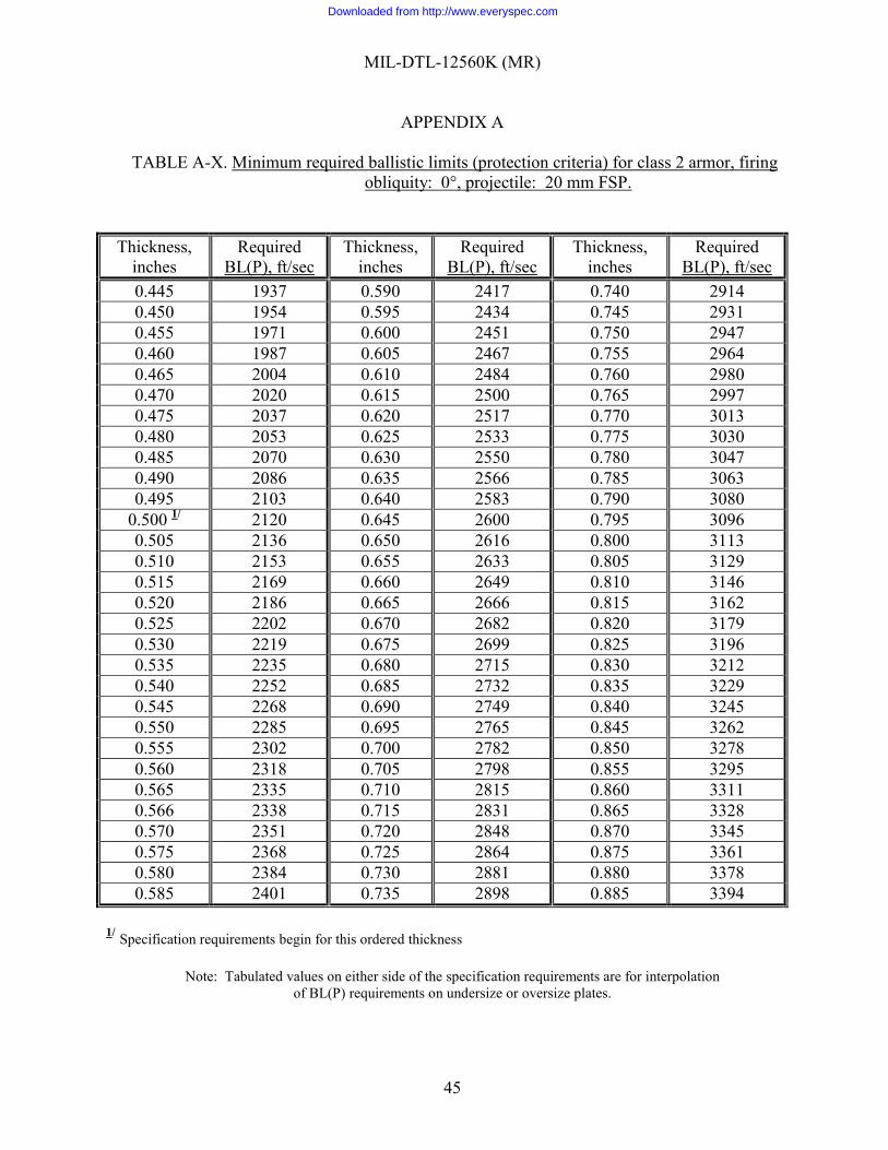
MIL-DTL-12560K (MR)
APPENDIX A
45
TABLE A-X. Minimum required ballistic limits (protection criteria) for class 2 armor, firing obliquity: 0°, projectile: 20 mm FSP.
Thickness, inches
Required BL(P), ft/sec
Thickness, inches
Required BL(P), ft/sec
Thickness, inches
Required BL(P), ft/sec
0.445 1937 0.590 2417 0.740 2914 0.450 1954 0.595 2434 0.745 2931 0.455 1971 0.600 2451 0.750 2947 0.460 1987 0.605 2467 0.755 2964 0.465 2004 0.610 2484 0.760 2980 0.470 2020 0.615 2500 0.765 2997 0.475 2037 0.620 2517 0.770 3013 0.480 2053 0.625 2533 0.775 3030 0.485 2070 0.630 2550 0.780 3047 0.490 2086 0.635 2566 0.785 3063 0.495 2103 0.640 2583 0.790 3080
0.500 1/ 2120 0.645 2600 0.795 3096 0.505 2136 0.650 2616 0.800 3113 0.510 2153 0.655 2633 0.805 3129 0.515 2169 0.660 2649 0.810 3146 0.520 2186 0.665 2666 0.815 3162 0.525 2202 0.670 2682 0.820 3179 0.530 2219 0.675 2699 0.825 3196 0.535 2235 0.680 2715 0.830 3212 0.540 2252 0.685 2732 0.835 3229 0.545 2268 0.690 2749 0.840 3245 0.550 2285 0.695 2765 0.845 3262 0.555 2302 0.700 2782 0.850 3278 0.560 2318 0.705 2798 0.855 3295 0.565 2335 0.710 2815 0.860 3311 0.566 2338 0.715 2831 0.865 3328 0.570 2351 0.720 2848 0.870 3345 0.575 2368 0.725 2864 0.875 3361 0.580 2384 0.730 2881 0.880 3378 0.585 2401 0.735 2898 0.885 3394
1/ Specification requirements begin for this ordered thickness
Note: Tabulated values on either side of the specification requirements are for interpolation of BL(P) requirements on undersize or oversize plates.
Downloaded from http://www.everyspec.com
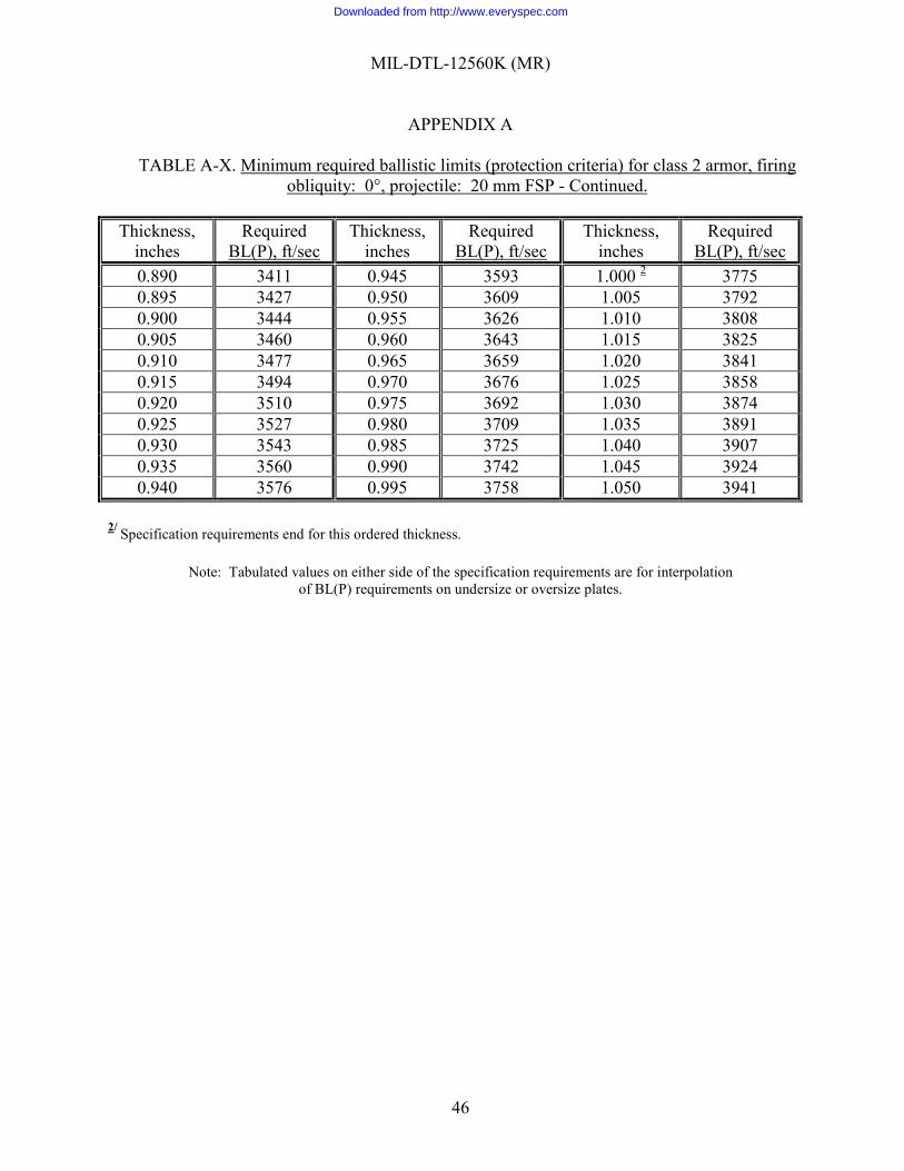
MIL-DTL-12560K (MR)
APPENDIX A
46
TABLE A-X. Minimum required ballistic limits (protection criteria) for class 2 armor, firing obliquity: 0°, projectile: 20 mm FSP - Continued.
Thickness,
inches Required
BL(P), ft/sec Thickness,
inches Required
BL(P), ft/sec Thickness,
inches Required
BL(P), ft/sec
0.890 3411 0.945 3593 1.000 2 3775 0.895 3427 0.950 3609 1.005 3792 0.900 3444 0.955 3626 1.010 3808 0.905 3460 0.960 3643 1.015 3825 0.910 3477 0.965 3659 1.020 3841 0.915 3494 0.970 3676 1.025 3858 0.920 3510 0.975 3692 1.030 3874 0.925 3527 0.980 3709 1.035 3891 0.930 3543 0.985 3725 1.040 3907 0.935 3560 0.990 3742 1.045 3924 0.940 3576 0.995 3758 1.050 3941
2/ Specification requirements end for this ordered thickness.
Note: Tabulated values on either side of the specification requirements are for interpolation of BL(P) requirements on undersize or oversize plates.
Downloaded from http://www.everyspec.com
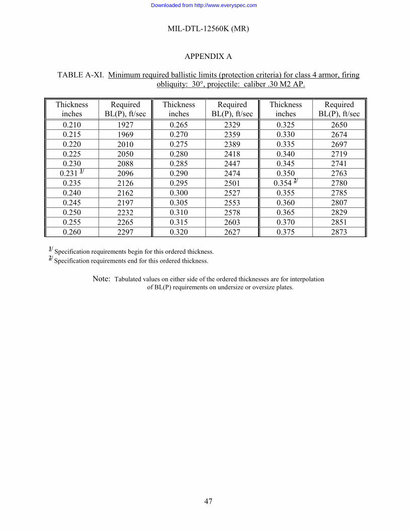
MIL-DTL-12560K (MR)
APPENDIX A
47
TABLE A-XI. Minimum required ballistic limits (protection criteria) for class 4 armor, firing obliquity: 30°, projectile: caliber .30 M2 AP.
Thickness
inches Required
BL(P), ft/sec Thickness
inches Required
BL(P), ft/sec Thickness
inches Required
BL(P), ft/sec
0.210 1927 0.265 2329 0.325 2650 0.215 1969 0.270 2359 0.330 2674 0.220 2010 0.275 2389 0.335 2697 0.225 2050 0.280 2418 0.340 2719 0.230 2088 0.285 2447 0.345 2741
0.231 1/ 2096 0.290 2474 0.350 2763 0.235 2126 0.295 2501 0.354 2/ 2780 0.240 2162 0.300 2527 0.355 2785 0.245 2197 0.305 2553 0.360 2807 0.250 2232 0.310 2578 0.365 2829 0.255 2265 0.315 2603 0.370 2851 0.260 2297 0.320 2627 0.375 2873
1/ Specification requirements begin for this ordered thickness. 2/ Specification requirements end for this ordered thickness.
Note: Tabulated values on either side of the ordered thicknesses are for interpolation
of BL(P) requirements on undersize or oversize plates.
Downloaded from http://www.everyspec.com
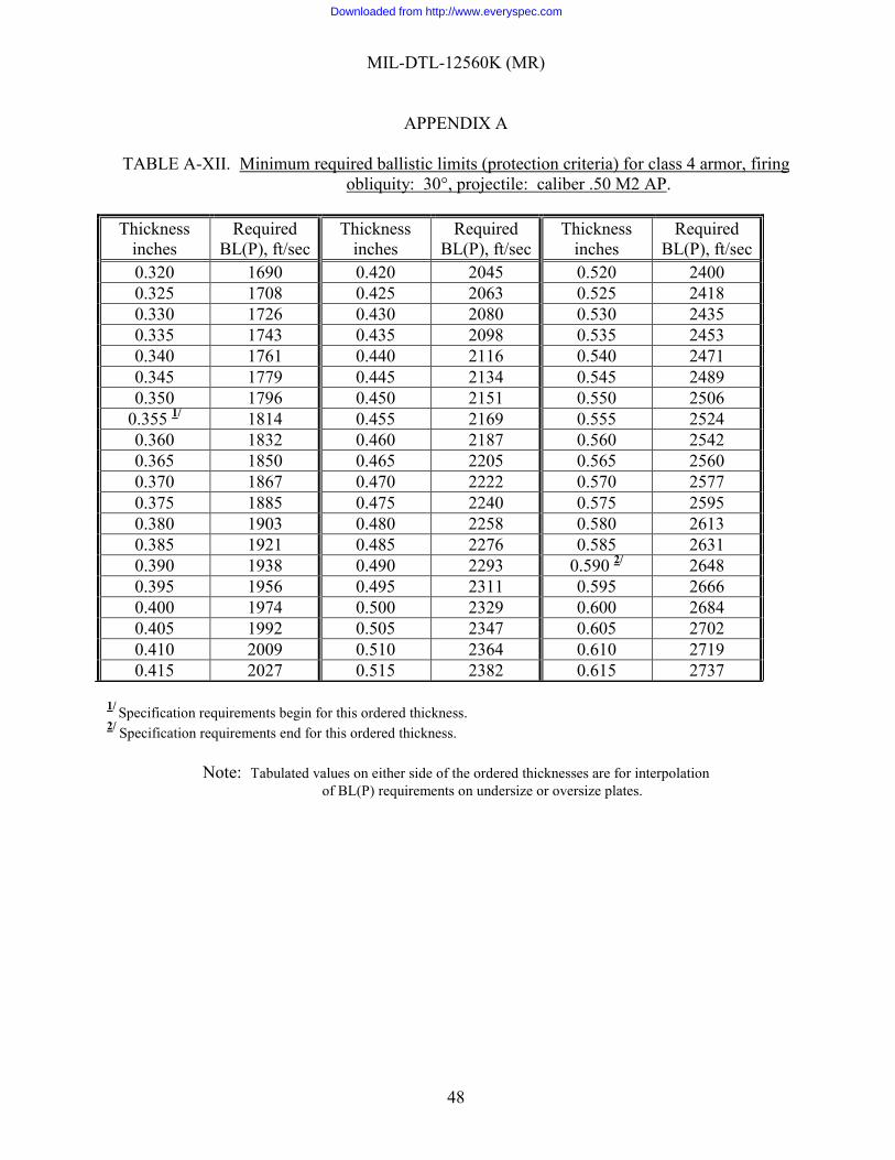
MIL-DTL-12560K (MR)
APPENDIX A
48
TABLE A-XII. Minimum required ballistic limits (protection criteria) for class 4 armor, firing obliquity: 30°, projectile: caliber .50 M2 AP.
Thickness
inches Required
BL(P), ft/sec Thickness
inches Required
BL(P), ft/sec Thickness
inches Required
BL(P), ft/sec
0.320 1690 0.420 2045 0.520 2400 0.325 1708 0.425 2063 0.525 2418 0.330 1726 0.430 2080 0.530 2435 0.335 1743 0.435 2098 0.535 2453 0.340 1761 0.440 2116 0.540 2471 0.345 1779 0.445 2134 0.545 2489 0.350 1796 0.450 2151 0.550 2506
0.355 1/ 1814 0.455 2169 0.555 2524 0.360 1832 0.460 2187 0.560 2542 0.365 1850 0.465 2205 0.565 2560 0.370 1867 0.470 2222 0.570 2577 0.375 1885 0.475 2240 0.575 2595 0.380 1903 0.480 2258 0.580 2613 0.385 1921 0.485 2276 0.585 2631 0.390 1938 0.490 2293 0.590 2/ 2648 0.395 1956 0.495 2311 0.595 2666 0.400 1974 0.500 2329 0.600 2684 0.405 1992 0.505 2347 0.605 2702 0.410 2009 0.510 2364 0.610 2719 0.415 2027 0.515 2382 0.615 2737
1/ Specification requirements begin for this ordered thickness. 2/ Specification requirements end for this ordered thickness.
Note: Tabulated values on either side of the ordered thicknesses are for interpolation of BL(P) requirements on undersize or oversize plates.
Downloaded from http://www.everyspec.com
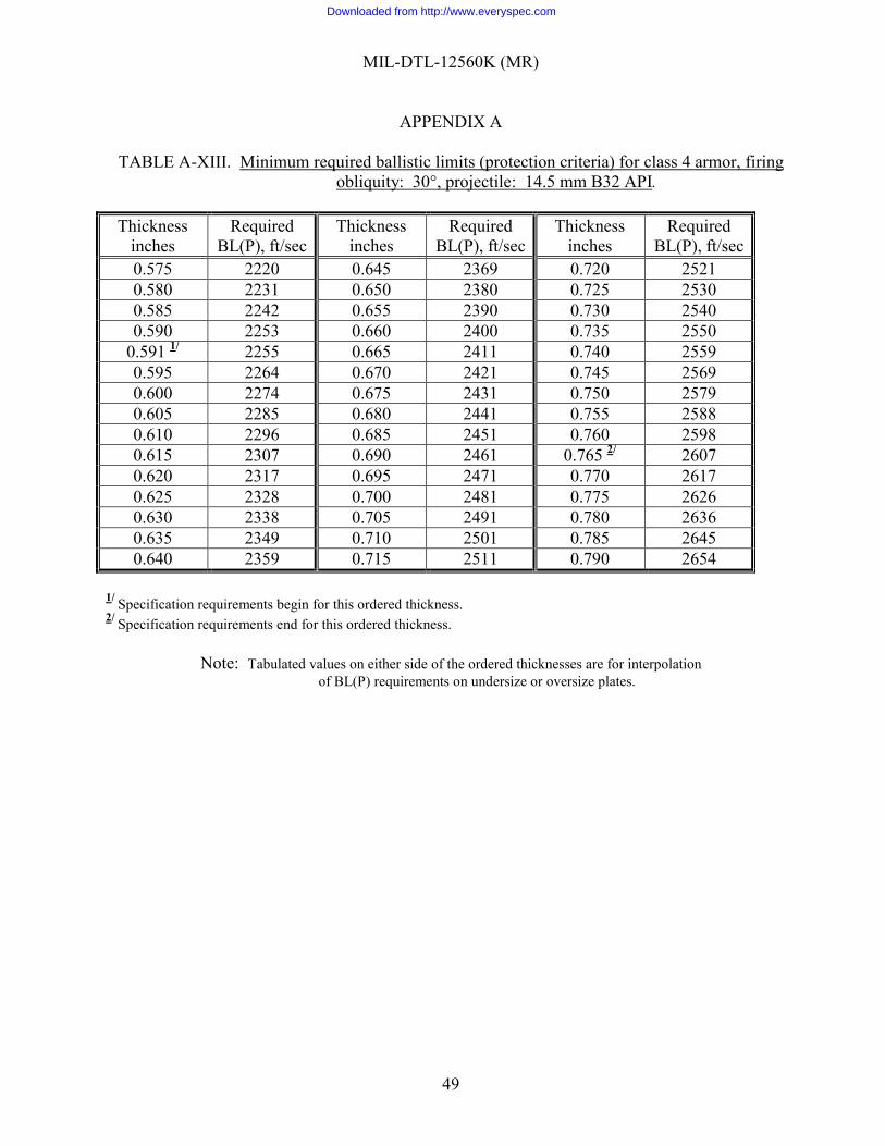
MIL-DTL-12560K (MR)
APPENDIX A
49
TABLE A-XIII. Minimum required ballistic limits (protection criteria) for class 4 armor, firing obliquity: 30°, projectile: 14.5 mm B32 API.
Thickness
inches Required
BL(P), ft/sec Thickness
inches Required
BL(P), ft/sec Thickness
inches Required
BL(P), ft/sec
0.575 2220 0.645 2369 0.720 2521 0.580 2231 0.650 2380 0.725 2530 0.585 2242 0.655 2390 0.730 2540 0.590 2253 0.660 2400 0.735 2550
0.591 1/ 2255 0.665 2411 0.740 2559 0.595 2264 0.670 2421 0.745 2569 0.600 2274 0.675 2431 0.750 2579 0.605 2285 0.680 2441 0.755 2588 0.610 2296 0.685 2451 0.760 2598 0.615 2307 0.690 2461 0.765 2/ 2607 0.620 2317 0.695 2471 0.770 2617 0.625 2328 0.700 2481 0.775 2626 0.630 2338 0.705 2491 0.780 2636 0.635 2349 0.710 2501 0.785 2645 0.640 2359 0.715 2511 0.790 2654
1/ Specification requirements begin for this ordered thickness. 2/ Specification requirements end for this ordered thickness.
Note: Tabulated values on either side of the ordered thicknesses are for interpolation of BL(P) requirements on undersize or oversize plates.
Downloaded from http://www.everyspec.com
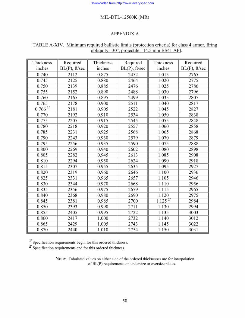
MIL-DTL-12560K (MR)
APPENDIX A
50
TABLE A-XIV. Minimum required ballistic limits (protection criteria) for class 4 armor, firing obliquity: 30°, projectile: 14.5 mm BS41 API.
Thickness
inches Required
BL(P), ft/sec Thickness
inches Required
BL(P), ft/sec Thickness
inches Required
BL(P), ft/sec
0.740 2112 0.875 2452 1.015 2765 0.745 2125 0.880 2464 1.020 2775 0.750 2139 0.885 2476 1.025 2786 0.755 2152 0.890 2488 1.030 2796 0.760 2165 0.895 2499 1.035 2807 0.765 2178 0.900 2511 1.040 2817
0.766 1/ 2181 0.905 2522 1.045 2827 0.770 2192 0.910 2534 1.050 2838 0.775 2205 0.915 2545 1.055 2848 0.780 2218 0.920 2557 1.060 2858 0.785 2231 0.925 2568 1.065 2868 0.790 2243 0.930 2579 1.070 2879 0.795 2256 0.935 2590 1.075 2888 0.800 2269 0.940 2602 1.080 2898 0.805 2282 0.945 2613 1.085 2908 0.810 2294 0.950 2624 1.090 2918 0.815 2307 0.955 2635 1.095 2927 0.820 2319 0.960 2646 1.100 2936 0.825 2331 0.965 2657 1.105 2946 0.830 2344 0.970 2668 1.110 2956 0.835 2356 0.975 2679 1.115 2965 0.840 2368 0.980 2690 1.120 2975 0.845 2381 0.985 2700 1.125 2/ 2984 0.850 2393 0.990 2711 1.130 2994 0.855 2405 0.995 2722 1.135 3003 0.860 2417 1.000 2732 1.140 3012 0.865 2429 1.005 2743 1.145 3022 0.870 2440 1.010 2754 1.150 3031
1/ Specification requirements begin for this ordered thickness. 2/ Specification requirements end for this ordered thickness.
Note: Tabulated values on either side of the ordered thicknesses are for interpolation of BL(P) requirements on undersize or oversize plates.
Downloaded from http://www.everyspec.com
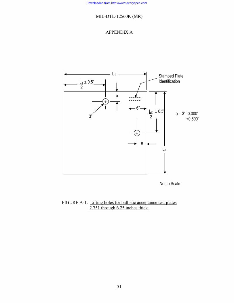
MIL-DTL-12560K (MR)
APPENDIX A
51
FIGURE A-1. Lifting holes for ballistic acceptance test plates 2.751 through 6.25 inches thick.
+
+
Stamped Plate Identification
a = 3” -0.000” +0.500”
L1
L1 ± 0.5” 2
6”
a
L2 ± 0.5” 2
L2
3”
a
Not to Scale
Downloaded from http://www.everyspec.com
MIL-DTL-12560K (MR)
52
CONCLUDING MATERIAL
Custodian: Preparing activity: Army - MR Army - MR Review activities: Project 9515-2012-001 Army - AR, AT, AV, TE DLA - IS
NOTE: The activities listed above were interested in this document as of the date of this document. Since organizations and responsibilities can change, you should verify the currency
of the information above using the ASSIST Online database at https://assist.dla.mil/.
Downloaded from http://www.everyspec.com


![[NOT MEASUREMENT SENSITIVE] SUPERSEDING MIL-P-197Heveryspec.com/MIL-SPECS/MIL-SPECS-MIL-DTL/download.php?spec=… · [not measurement sensitive] mil-dtl-197j 9 july 2000 superseding](https://static.fdocuments.us/doc/165x107/5b80c51f7f8b9af7088e17c6/not-measurement-sensitive-superseding-mil-p-not-measurement-sensitive-mil-dtl-197j.jpg)