AMERICAN SOCIETY FOR TESTING AND MATERIALS...
22
Downloaded from http://www.everyspec.com
Transcript of AMERICAN SOCIETY FOR TESTING AND MATERIALS...

Downloaded from http://www.everyspec.com
MIL-DTL-83528F
2
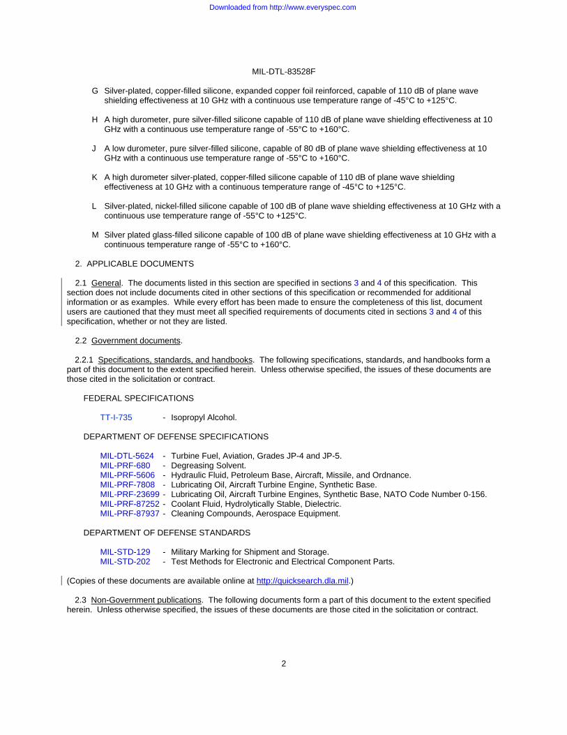
G Silver-plated, copper-filled silicone, expanded copper foil reinforced, capable of 110 dB of plane wave shielding effectiveness at 10 GHz with a continuous use temperature range of -45°C to +125°C.
H A high durometer, pure silver-filled silicone capable of 110 dB of plane wave shielding effectiveness at 10
GHz with a continuous use temperature range of -55°C to +160°C. J A low durometer, pure silver-filled silicone, capable of 80 dB of plane wave shielding effectiveness at 10
GHz with a continuous use temperature range of -55°C to +160°C. K A high durometer silver-plated, copper-filled silicone capable of 110 dB of plane wave shielding
effectiveness at 10 GHz with a continuous temperature range of -45°C to +125°C. L Silver-plated, nickel-filled silicone capable of 100 dB of plane wave shielding effectiveness at 10 GHz with a
continuous use temperature range of -55°C to +125°C. M Silver plated glass-filled silicone capable of 100 dB of plane wave shielding effectiveness at 10 GHz with a
continuous temperature range of -55°C to +160°C.
2. APPLICABLE DOCUMENTS 2.1 General. The documents listed in this section are specified in sections 3 and 4 of this specification. This section does not include documents cited in other sections of this specification or recommended for additional information or as examples. While every effort has been made to ensure the completeness of this list, document users are cautioned that they must meet all specified requirements of documents cited in sections 3 and 4 of this specification, whether or not they are listed.
2.2 Government documents. 2.2.1 Specifications, standards, and handbooks. The following specifications, standards, and handbooks form a part of this document to the extent specified herein. Unless otherwise specified, the issues of these documents are those cited in the solicitation or contract.
FEDERAL SPECIFICATIONS
TT-I-735 - Isopropyl Alcohol.
DEPARTMENT OF DEFENSE SPECIFICATIONS
MIL-DTL-5624 - Turbine Fuel, Aviation, Grades JP-4 and JP-5. MIL-PRF-680 - Degreasing Solvent. MIL-PRF-5606 - Hydraulic Fluid, Petroleum Base, Aircraft, Missile, and Ordnance. MIL-PRF-7808 - Lubricating Oil, Aircraft Turbine Engine, Synthetic Base. MIL-PRF-23699 - Lubricating Oil, Aircraft Turbine Engines, Synthetic Base, NATO Code Number 0-156. MIL-PRF-87252 - Coolant Fluid, Hydrolytically Stable, Dielectric. MIL-PRF-87937 - Cleaning Compounds, Aerospace Equipment.
DEPARTMENT OF DEFENSE STANDARDS
MIL-STD-129 - Military Marking for Shipment and Storage. MIL-STD-202 - Test Methods for Electronic and Electrical Component Parts.
(Copies of these documents are available online at http://quicksearch.dla.mil.) 2.3 Non-Government publications. The following documents form a part of this document to the extent specified herein. Unless otherwise specified, the issues of these documents are those cited in the solicitation or contract.
Downloaded from http://www.everyspec.com

MIL-DTL-83528F
3
AMERICAN SOCIETY FOR TESTING AND MATERIALS (ASTM) ASTM D395 - Standard Test Methods for Rubber Property - Compression Set. ASTM D412 - Standard Test Methods for Rubber Vulcanized and Thermoplastic Elastomers - Tension. ASTM D471 - Standard Test Method for Rubber Property-Effect of Liquids. ASTM D575 - Standard Test Methods for Rubber Properties in Compression. ASTM D624 - Standard Test Method for Tear Strength of Conventional Vulcanized Rubber and
Thermoplastic Elastomers. ASTM D792 - Standard Test Method for Density and Specific Gravity (Relative Density) of Plastics by
Displacement. ASTM D991 - Test Methods for Rubber Property - Volume Resistivity of Electrically Conductive and
Antistatic Products. ASTM D1329 - Standard Test Method for Evaluating Rubber Property – Retraction at Lower
Temperatures (TR Test). ASTM D2240 - Standard Test Method for Rubber Property – Durometer Hardness. ASTM D4814 - Standard Specification for Automotive Spark-Ignition Engine Fuel.
(Copies of these documents are available online at http://www.astm.org/.) INSTITUTE OF ELECTRICAL AND ELECTRONIC ENGINEERS (IEEE) IEEE299 - Measuring the Effectiveness of Enclosures, Electromagnetic Shielding. (Copies of this documents are available online at http://www.ieee.org/.) SOCIETY OF AUTOMOTIVE ENGINEERS INC. (SAE) SAE-AMS-1424 - Deicing/Anti-Icing Fluid, Aircraft, SAE Type I. (Copies of this document are available online at http://www.sae.org/.)
2.4 Order of precedence. Unless otherwise noted herein or in the contract, in the event of a conflict between the text of this document and the references cited herein (except for related specification sheets), the text of this document takes precedence. Nothing in this document, however, supersedes applicable laws and regulations unless a specific exemption has been obtained.
3. REQUIREMENTS
3.1 Specification sheets. The individual item requirements shall be as specified herein and in accordance with the applicable specification sheet. In the event of any conflict between the requirements of this specification and the specification sheet, the latter shall govern.
3.2 Qualification. The gaskets furnished under this specification shall be a product which has been tested, and has passed the qualification inspection specified herein, and has been listed on or approved for listing on the applicable Qualified Products List (QPL).
3.3 Visual inspection. Visual inspection shall be made in accordance with 4.5.2.
3.3.1 Dimensions. The dimensions and tolerances for qualification samples are controlled by the applicable test procedure specification (see 4.5). Product dimensions and tolerances shall meet the requirements of the applicable product specification (see 3.1) controlled by this specification.
3.3.2 Characteristics. Unless otherwise specified (see 3.1), standard test specimens shall meet the characteristics indicated in table I. These properties shall be as specified on the applicable specification sheet for actual product-form.
Downloaded from http://www.everyspec.com

MIL-DTL-83528F
4
3.4 Marking. Gaskets shall not be marked, except that embossing of .0005 inch maximum is allowed. Unit packs shall be marked in accordance with MIL-STD-129 with the following:
a. Military PIN (see 1.2.1 and 3.1). b. Manufacturer's source code. c. Material type (see 1.2.1.1). d. Manufacturing cure date code. e. Manufacturing batch number. f. Fabricator plant code symbol, when applicable.
3.5 Cleaning and drying. Gaskets shall be cleaned and dried by any suitable process or processes that are not
injurious to the item. 3.6 Preservative application. Preservatives, if used, shall be a noncorrosive, sulfur free stiffener within each unit
pack to protect the gasket.
3.7 Recycled, recovered, environmentally preferable, or biobased materials. Recycled, recovered, environmentally preferable, or biobased materials should be used to the maximum extent possible, provided that the material meets or exceeds the operational and maintenance requirements, and promotes economically advantageous life cycle costs.
3.8 Pure tin. The use of pure tin, as an underplate or final finish, is prohibited both internally and externally. Tin
content of gasket and solder shall not exceed 97 percent, by mass. Tin shall be alloyed with a minimum of 3 percent lead, by mass (see 6.4).
3.9 Workmanship. Gaskets shall be processed in such a manner as to be representative of controlled industrial
techniques. All surfaces shall be free from burrs, die marks, chatter marks, scratches, dirt, grease, scale, splinters, and other defects that could affect life, serviceability, performance, or appearance of the gasket.
4. VERIFICATION 4.1 Classification of inspections. The inspection requirements specified herein are classified as follows:
a. Qualification inspection (see 4.2). b. In-process inspection (see 4.3). c. Conformance inspection (see 4.4).
Downloaded from http://www.everyspec.com

MIL-DTL-83528F
5
TABLE I. Characteristics.
Item No.
Inspection Units Toler-ance
Material type
A B C D E F G H J K L M
1. Operating temperature range
°C N/A -55 -55 -55 -55 -55 -65 -45 -55 -55 -45 -55 -55
+125 +160 +125 +160 +160 +160 +125 +160 +160 +125 +125 +160
2. Specific gravity Sp gr
23/23°C
±13% 3.5 2.0 4.0 2.0 3.5 4.0 4.75
1/
4.0 1.7 3.5 4.0 1.9
3. Hardness Shore A
units
±7 65 65 75 70 65 75 80 80 45 85 75 65
4. Compression/ deflection
Percent Min 3.5 3.5 3.5 3.5 2.5 3.5 2.5 2.5 8.0 2.5 3.5 3.5
5. Tensile strength Pounds per
square inch
Min 200 200 180 180 300 250 600 400 150 400 200 200
6. Elongation Percent Min 100 100 100 60 200 100 20 90 50 100 100 100
Max 300 300 300 260 500 300 N/A 290 250 300 300 300
7. Compression set Percent Max 32.0 32.0 35.0 30.0 45.0 60.0 N/A 60.0 35.0 35.0 32.0 30.0
8. Tear strength Pounds per
inch
Min 25 30 35 35 50 40 70 60 20 40 30 30
9. Volume resistivity (as received)
Ohm-cm Max .004 .008 .010 .012 .002 .002 .007 .005 .010 .005 .005 .006
10. Shielding effectiveness 20 MHz-10 GHz (E-Field)
dB Min 110 100 110 90 110 110 110 110 80 110 100 100
11. Electrical stability during vibration
During Ohm-cm Max .006 .012 .015 .015 .010 .010 .010 .006 .015 .010 .010 .009
After .004 .008 .010 .012 .002 .002 .007 .005 .010 .005 .005 .006
12. Electrical stability after break
Ohm-cm Max .008 .015 .015 .015 .010 .010 N/A .006 .020 .010 .010 .009
13. Low temperature flex
TR10 °C Max -55 -55 -55 -55 -55 -65 N/A -55 -55 -45 -55 -55
TR70 -55 -55 -40 -40 -40 -40 N/A -40 -55 -35 -55 -55
14. Volume resistivity (after life testing)
Ohm-cm Max .010 .010 .015 .015 .010 .010 .010 .008 .015 .010 .010 .015
15. Volume resistivity after electromagnetic pulse (EMP) exposure 2/
Ohm-cm Max .010 .010 .015 .015 .010 .010 .010 .008 .015 .010 .010 .015
16. Fluid immersion 3/ 4/
--- --- N/S N/S SUR SUR N/S SUR N/S N/S N/S N/S N/S N/S
1/ Tolerance on material G only is ±0.75 sp gr 23/23°C. 2/ 0.9 kA per linear inch of perimeter. 3/ N/S = Not survivable; SUR = Survivable. 4/ Maximum volume swell of 25 percent and maximum change in hardness of 15 shore A units.
Downloaded from http://www.everyspec.com

MIL-DTL-83528F
6
4.2 Qualification inspection. The qualification inspection shall be performed at a laboratory acceptable to the Government (see 6.3) on sample units produced with equipment and procedures normally used in production. Qualification inspection shall consist of the tests and inspections specified in table II.
4.2.1 Sample size. Samples shall be selected from normal production from one batch for each material type
(see 1.2.1.1) for which qualification is sought. Actual sample size shall be sufficient to perform all the inspections in table II. Size and shape of the test specimens shall be in accordance with the applicable test method. A single 360 square inch by .055 in (1.40 mm) to .120 in (3.05 mm) thick .027 in (0.69 mm) ±.005 in (± 0.13 mm)thick for type G) sample should be sufficient for qualification testing.
4.2.2 Inspection routine. The sample shall be subjected to the inspections specified. When the specimen is to
be used for more than one test, the order of testing shall be accomplished in a sequence that will not effect the results of subsequent testing.
4.2.3 Failures. One or more failures shall be cause for refusal to grant qualification approval. Failure criteria for
specimens shall be as specified in the applicable method paragraph or requirement paragraph. 4.2.4 Retention of qualification. To retain qualification, the contractor shall forward a report at 12-month
intervals to the qualifying activity. The qualifying activity shall establish the initial reporting date. The report shall consist of a summary of the results of the in-process inspection and the tests performed for inspection of product for delivery (group A), indicating, as a minimum: The number of lots that have passed, the number that have failed, and actual test data for periodic inspection (group B) if performed in that reporting period.
Failure to submit the report within 30 days after the end of each 12-month period may result in loss of qualification for the product. In addition to the periodic submission of inspection data, the contractor shall immediately notify the qualifying activity at any time during the 12-month period that the inspection data indicates failure of the qualified product to meet the requirements of this specification.
In the event that no production occurred during the reporting period, a report shall be submitted certifying that the company still has the capabilities and facilities necessary to produce the item.
Actual in-process and group A test data shall be submitted to the qualifying activity upon their request.
4.2.5 Modification of qualified products. Except for changes in color which do not affect the performance of the
gaskets, no modification of the composition of any qualified product shall be made without requalification. The qualified product manufacturer remains responsible for continuing to meet all the requirements of this specification.
4.2.6 Extent of qualification. Qualification of a material type (see 1.2.1.1) shall be extended to all gaskets made
from that material type. Qualification shall not be extended from one material type to another. 4.3 In-process inspection. 4.3.1 In-process inspection. The in-process inspection shall consist of the inspections specified in table III in the
order shown.
Downloaded from http://www.everyspec.com
MIL-DTL-83528F
7
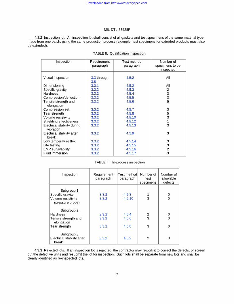
4.3.2 Inspection lot. An inspection lot shall consist of all gaskets and test specimens of the same material type made from one batch, using the same production process (example, test specimens for extruded products must also be extruded).
TABLE II. Qualification inspection.
Inspection Requirement
paragraph Test method paragraph
Number of specimens to be
inspected Visual inspection Dimensioning Specific gravity Hardness Compression/deflection Tensile strength and elongation Compression set Tear strength Volume resistivity Shielding effectiveness Electrical stability during vibration Electrical stability after break Low temperature flex Life testing EMP survivability Fluid immersion
3.3 through 3.8 3.3.1 3.3.2 3.3.2 3.3.2 3.3.2 3.3.2 3.3.2 3.3.2 3.3.2 3.3.2 3.3.2 3.3.2 3.3.2 3.3.2 3.3.2
4.5.2 4.5.2 4.5.3 4.5.4 4.5.5 4.5.6 4.5.7 4.5.8 4.5.10 4.5.12 4.5.13 4.5.9 4.5.14 4.5.15 4.5.16 4.5.17
All
All 2 3 3 5 3 5 3 1 3 3 3 3 2 3
TABLE III. In-process inspection
Inspection
Requirement paragraph
Test method paragraph
Number of
test specimens
Number of allowable defects
Subgroup 1
Specific gravity Volume resistivity (pressure probe)
Subgroup 2 Hardness Tensile strength and elongation Tear strength
Subgroup 3 Electrical stability after break
3.3.2 3.3.2
3.3.2 3.3.2
3.3.2
3.3.2
4.5.3 4.5.10
4.5.4 4.5.6
4.5.8
4.5.9
1 3
2 3
3
2
0 0
0 0
0
0
4.3.3 Rejected lots. If an inspection lot is rejected, the contractor may rework it to correct the defects, or screen
out the defective units and resubmit the lot for inspection. Such lots shall be separate from new lots and shall be clearly identified as re-inspected lots.
Downloaded from http://www.everyspec.com
MIL-DTL-83528F
8
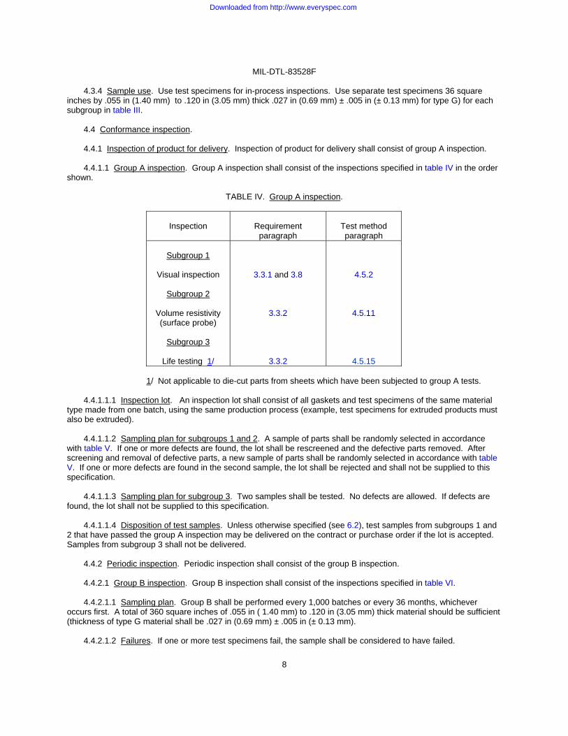
4.3.4 Sample use. Use test specimens for in-process inspections. Use separate test specimens 36 square inches by .055 in (1.40 mm) to .120 in (3.05 mm) thick .027 in (0.69 mm) ± .005 in (± 0.13 mm) for type G) for each subgroup in table III.
4.4 Conformance inspection. 4.4.1 Inspection of product for delivery. Inspection of product for delivery shall consist of group A inspection. 4.4.1.1 Group A inspection. Group A inspection shall consist of the inspections specified in table IV in the order
shown.
TABLE IV. Group A inspection.
Inspection
Requirement
paragraph
Test method paragraph
Subgroup 1
Visual inspection
Subgroup 2
Volume resistivity (surface probe)
Subgroup 3
Life testing 1/
3.3.1 and 3.8
3.3.2
3.3.2
4.5.2
4.5.11
4.5.15
1/ Not applicable to die-cut parts from sheets which have been subjected to group A tests.
4.4.1.1.1 Inspection lot. An inspection lot shall consist of all gaskets and test specimens of the same material type made from one batch, using the same production process (example, test specimens for extruded products must also be extruded).
4.4.1.1.2 Sampling plan for subqroups 1 and 2. A sample of parts shall be randomly selected in accordance with table V. If one or more defects are found, the lot shall be rescreened and the defective parts removed. After screening and removal of defective parts, a new sample of parts shall be randomly selected in accordance with table V. If one or more defects are found in the second sample, the lot shall be rejected and shall not be supplied to this specification.
4.4.1.1.3 Sampling plan for subgroup 3. Two samples shall be tested. No defects are allowed. If defects are found, the lot shall not be supplied to this specification.
4.4.1.1.4 Disposition of test samples. Unless otherwise specified (see 6.2), test samples from subgroups 1 and 2 that have passed the group A inspection may be delivered on the contract or purchase order if the lot is accepted. Samples from subgroup 3 shall not be delivered.
4.4.2 Periodic inspection. Periodic inspection shall consist of the group B inspection.
4.4.2.1 Group B inspection. Group B inspection shall consist of the inspections specified in table VI.
4.4.2.1.1 Sampling plan. Group B shall be performed every 1,000 batches or every 36 months, whichever occurs first. A total of 360 square inches of .055 in ( 1.40 mm) to .120 in (3.05 mm) thick material should be sufficient (thickness of type G material shall be .027 in (0.69 mm) ± .005 in (± 0.13 mm).
4.4.2.1.2 Failures. If one or more test specimens fail, the sample shall be considered to have failed.
Downloaded from http://www.everyspec.com

MIL-DTL-83528F
9
TABLE V. Sampling plan. 1/
Lot size Subgroup 1 Subgroup 2
2 to 25 26 to 50 51 to 90 91 to 150 151 to 280 281 to 500 501 to 1,200 1,201 to 3,200 3,201 to 10,000 10,001 to 35,000 35,001 and over
3 5 6 7 10 11 15 18 22 29 29
5 5 7 11 13 16 19 23 29 35 40
1/ The acceptance number in all cases is zero.
TABLE VI. Group B inspection.
Inspection
Requirement paragraph
Method
paragraph
Number of specimens
Shielding effectiveness Compression/deflection Compression set Electrical stability during vibration Low temperature flex EMP survivability Fluid immersion
3.3.2 3.3.2 3.3.2 3.3.2
3.3.2 3.3.2 3.3.2
4.5.12 4.5.5 4.5.7
4.5.13
4.5.14 4.5.16 4.5.17
1 3 3 3 3 2 3
4.4.2.1.3 Disposition of test specimens. Unless otherwise specified, test specimens that have passed group B
inspection shall not be delivered on the contract or purchase order.
4.4.2.1.4 Noncompliance. If a test specimen fails to pass group B inspection, the manufacturer shall notify the qualifying activity, affected customers, and the cognizant inspection activity of such failure and take corrective action on the materials or processes, or both, as warranted. Acceptance and shipment of the product shall be discontinued until corrective action that is acceptable to the qualifying activity has been taken. After the corrective action has been taken, group B inspection shall be repeated on additional sample units (all inspections, or the inspection that the original sample failed, at the option of the qualifying activity). Group A inspection maybe reinstituted; however, final acceptance and shipment shall be withheld until the group B inspections have shown that the corrective action was successful. In the event of failure after re-inspection, information concerning the failure shall he furnished to the cognizant inspection activity and the qualifying activity.
4.4.3 Inspection of packaging. The sampling and inspection of the packing shall be in accordance with the quality assurance provisions of the applicable container specification. The inspection marking for shipment and storage shall be in accordance with the marking requirements of MIL-STD-129.
4.4.4 Reporting of results. A copy of test reports shall be furnished for all conformance tests required by this specification, and shall be signed by an authorized representative of the manufacturer or the laboratory performing the tests.
Downloaded from http://www.everyspec.com
MIL-DTL-83528F
10
4.5 Methods of inspections and tests. 4.5.1 Test conditions. Unless otherwise specified, the inspections and tests shall be performed at a temperature
of 23°C ±5°C, a relative humidity of 45 to 75 percent in accordance with MIL-STD-202, and atmospheric pressure of 650 to 800 millimeters of mercury.
4.5.2 Visual inspection. Visual inspections shall be made to verify conformance to the requirements for
materials, dimensions, marking, cleanliness, preservation, and workmanship (see 3.3). 4.5.3 Specific gravity. The specific gravity of the material shall be determined on test specimens in accordance
with ASTM D792, method A. Tolerance on specific gravity shall be ±13 percent of specified amount (see 3.3.2). After material has been qualified, recorded in-process inspection values must be maintained within a tolerance of ±0.25 of the manufacturer's own nominal value, which must be established such that the actual qualification sample value is also within this allowable production range.
4.5.4 Hardness. The hardness of the material shall be determined using a type A durometer in accordance with
ASTM D2240.
4.5.5 Compression/deflection. The compression/deflection of the material (an indication of compressive modulus) shall be determined on test specimens in accordance with ASTM D575, method B, except test sample shall be .062 ±.007 inch thick, using a compressive load of 100 pound-force per square inch.
4.5.6 Tensile strength and elongation. The tensile strength and elongation of the material shall be determined on test specimens in accordance with ASTM D412, method A, die C.
4.5.7 Compression set. The compression set of the material shall be determined in accordance with ASTM D395, method B, after 70 hours at +100°C (212°F).
4.5.8 Tear strength. The tear strength of the material shall be determined on test specimens in accordance with ASTM D624, using die C.
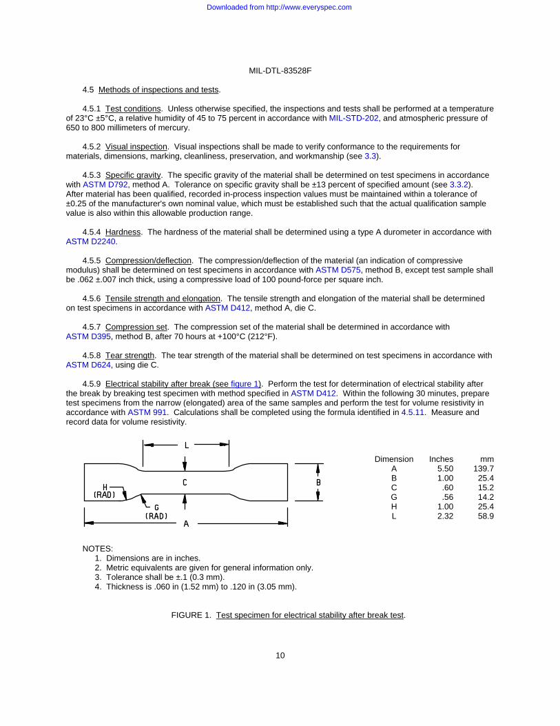
4.5.9 Electrical stability after break (see figure 1). Perform the test for determination of electrical stability after the break by breaking test specimen with method specified in ASTM D412. Within the following 30 minutes, prepare test specimens from the narrow (elongated) area of the same samples and perform the test for volume resistivity in accordance with ASTM 991. Calculations shall be completed using the formula identified in 4.5.11. Measure and record data for volume resistivity.
NOTES:
1. Dimensions are in inches. 2. Metric equivalents are given for general information only. 3. Tolerance shall be ±.1 (0.3 mm). 4. Thickness is .060 in (1.52 mm) to .120 in (3.05 mm).
FIGURE 1. Test specimen for electrical stability after break test.
Dimension Inches mmA 5.50 139.7B 1.00 25.4C .60 15.2G .56 14.2H 1.00 25.4L 2.32 58.9
Downloaded from http://www.everyspec.com

MIL-DTL-83528F
11
4.5.10 Volume resistivity (pressure probe). 4.5.10.1 Equipment.
a. Ohmmeter: Equipment having a range of 104 to –5 ohms with accuracy of ±.02 percent of reading. b. Thickness gauge: Equipped with .750 in (19.05 mm) diameter foot anvil and measuring in increments of
.001 inch under 4 ounces load. c. Silver- or gold-plated electrodes: Having a contacting surface area equal to .25 square inch (.564 in
(14.33 mm) diameter) with suitable provisions for attaching ohmmeter leads (see figure 2).
NOTES:
1. Dimensions are in inches. 2. Metric equivalents (in parentheses) are given for general information only.
FIGURE 2. Volume resistivity (pressure probe). d. Appropriate fixture or apparatus having capabilities of supporting silver electrodes, test specimen, and
suitable means of applying 100 psi pressure across contacting surface area of specimen between electrodes (or 25 pounds force).
4.5.10.2 Preparation of materials for testing. The material to be tested shall consist of:
a. Test specimens with a thickness of .055 in (1.40 mm) to .120 in (3.05mm) (.027 in (0.69 mm) ± .005 in (0.13 mm) in for type G). Use disc of .564 in (14.33 mm) ±.010 in (0.25 mm) diameter.
b. The surfaces of the material shall be clean and free of dirt, foreign matter, and indentations. c. The specimens shall be conditioned for at least three hours at standard temperature of 23°C ±5°C and at
45 to 75 percent RH in accordance with MIL-STD-202. 4.5.10.3 Preparation of testing electrodes.
a. For minimal contact resistance, electrodes shall be cleaned by wiping with alcohol prior to using. b. Electrodes must be properly aligned and contact faces must be flat and parallel to each other.
Downloaded from http://www.everyspec.com
MIL-DTL-83528F
12
4.5.10.4 Test procedure.
a. Measure and record thickness of material at contact areas to be tested using thickness gauge.
b. Material being tested must have sufficient area to contact entire electrode area.
c. Position material between electrodes and apply pressure of 100 ±5 psi across contact surface area (25 pounds load or force).
d. Maintain constant pressure until electrical requirement is met with a maximum time of two minutes.
4.5.10.5 Calculation. Calculate volume resistivity in ohms-cm using the following formula:
=
Where: = Volume resistivity (ohm-cm) R = Observed resistance (ohms) A = Area of specimen (cm2) L = Thickness of specimen (cm)
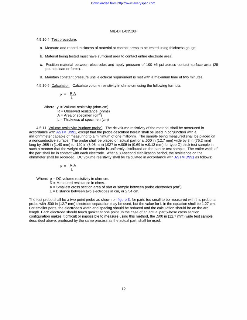
4.5.11 Volume resistivity (surface probe). The dc volume resistivity of the material shall be measured in
accordance with ASTM D991, except that the probe described herein shall be used in conjunction with a milliohmmeter capable of measuring to a minimum of one milliohm. The sample being measured shall be placed on a nonconductive surface. The probe shall be placed on actual part or a .500 in (12.7 mm) wide by 3 in (76.2 mm) long by .055 in (1.40 mm) to .120 in (3.05 mm) (.027 in ±.005 in (0.69 in ±.0.13 mm) for type G) thick test sample in such a manner that the weight of the test probe is uniformly distributed on the part or test sample. The entire width of the part shall be in contact with each electrode. After a 30-second stabilization period, the resistance on the ohmmeter shall be recorded. DC volume resistivity shall be calculated in accordance with ASTM D991 as follows:
=
Where: = DC volume resistivity in ohm-cm. R = Measured resistance in ohms. A = Smallest cross section area of part or sample between probe electrodes (cm2). L = Distance between two electrodes in cm, or 2.54 cm.
The test probe shall be a two-point probe as shown on figure 3, for parts too small to be measured with this probe, a probe with .500 in (12.7 mm) electrode separation may be used, but the value for L in the equation shall be 1.27 cm. For smaller parts, the electrode's width and spacing should be reduced and the calculation should be on the arc length. Each electrode should touch gasket at one point. In the case of an actual part whose cross section configuration makes it difficult or impossible to measure using this method, the .500 in (12.7 mm) wide test sample described above, produced by the same process as the actual part, shall be used.
R A L
R A L
Downloaded from http://www.everyspec.com

MIL-DTL-83528F
13
Inches mm .005 .01 .187 .500 1.000
0.13 0.2 4.75 12.70 25.40
NOTES:
1. Dimensions are in inches. 2. Metric equivalents are given for general information only. 3. Where applicable the probe will be placed on the flat surface of the item. 4. Unless otherwise indicated, tolerance is ±.010 (0.25 mm).
FIGURE 3. Volume resistivity (surface probe).
4.5.12 Shielding effectiveness.
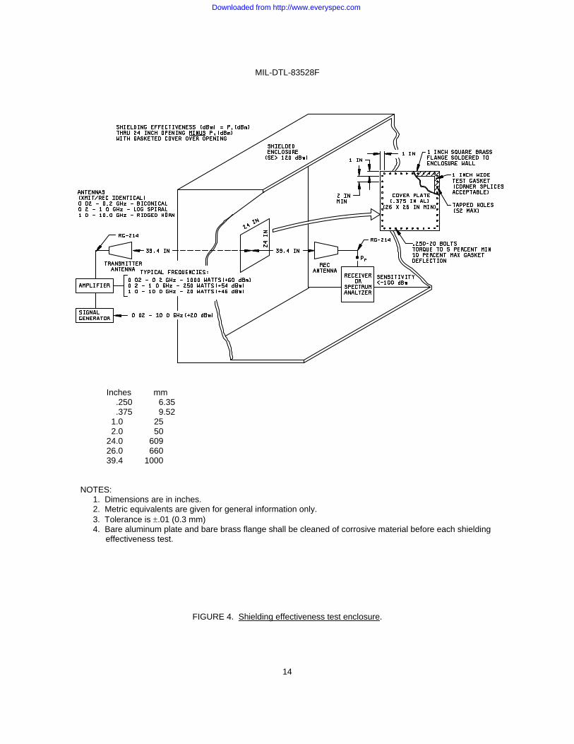
a. A relative measurement of the shielding effectiveness of the material shall be made in accordance with a documented method acceptable to the qualifying activity (see 6.1.4). Shielding effectiveness shall be defined as the ability of a gasket material to electrically bond a test cover panel to an enclosure flange such that radiated RF through a 24-by-24-in (61-by-61 cm) opening is attenuated by the factors specified. The test configuration of figure 4 will provide more than 120 dB of dynamic range (E-field) through the 24-by-24-in (61-by-61 cm) opening for frequencies above 20 MHz. Swept frequency techniques are encouraged, but as a minimum, data shall be recorded at the 1, 2, 4, 6, and 8 times frequencies of each decade in the 20 MHz through 10 GHz range. The position of antennas, equipment, or other metal-containing objects in the shielded room should not be moved between open-aperture and closed-aperture measurements. An optional shielding effectiveness test can be conducted with the transmitting antenna inside the enclosure and the receiving antenna outside the enclosure and sufficient dynamic range can be achieved at all frequencies. NOTE: The enclosure must be large enough that no part of the transmitting antenna is within one meter of any enclosure surface.
Downloaded from http://www.everyspec.com
MIL-DTL-83528F
14
Inches mm .250 6.35 .375 9.52 1.0 25 2.0 50 24.0 609 26.0 660 39.4 1000
NOTES: 1. Dimensions are in inches. 2. Metric equivalents are given for general information only. 3. Tolerance is .01 (0.3 mm) 4. Bare aluminum plate and bare brass flange shall be cleaned of corrosive material before each shielding
effectiveness test.
FIGURE 4. Shielding effectiveness test enclosure.
Downloaded from http://www.everyspec.com
MIL-DTL-83528F
15
b. It may not be inferred that the same level of shielding effectiveness provided by a gasket material tested in the enclosure of figure 4 would be provided in an actual equipment flange, since many mechanical factors of the flange design (tolerances, stiffness, fastener location, and size) will affect shielding effectiveness. This procedure provides data applicable only to the test enclosure and cover panel design of figure 4, but which is useful for making comparisons between different gasket materials.
NOTE: Metal surfaces which will contact the gasket surface must be cleaned of corrosion deposits and other insulating material before each test.
4.5.13 Electrical stability during vibration. The vibration resistance of the material shall be determined using the electrical resistance apparatus and the following procedures:
a. Prepare a rectangular, flat gasket sample with external dimensions of 2.75 ±.030 in (69.9 ± 0.76 mm) by
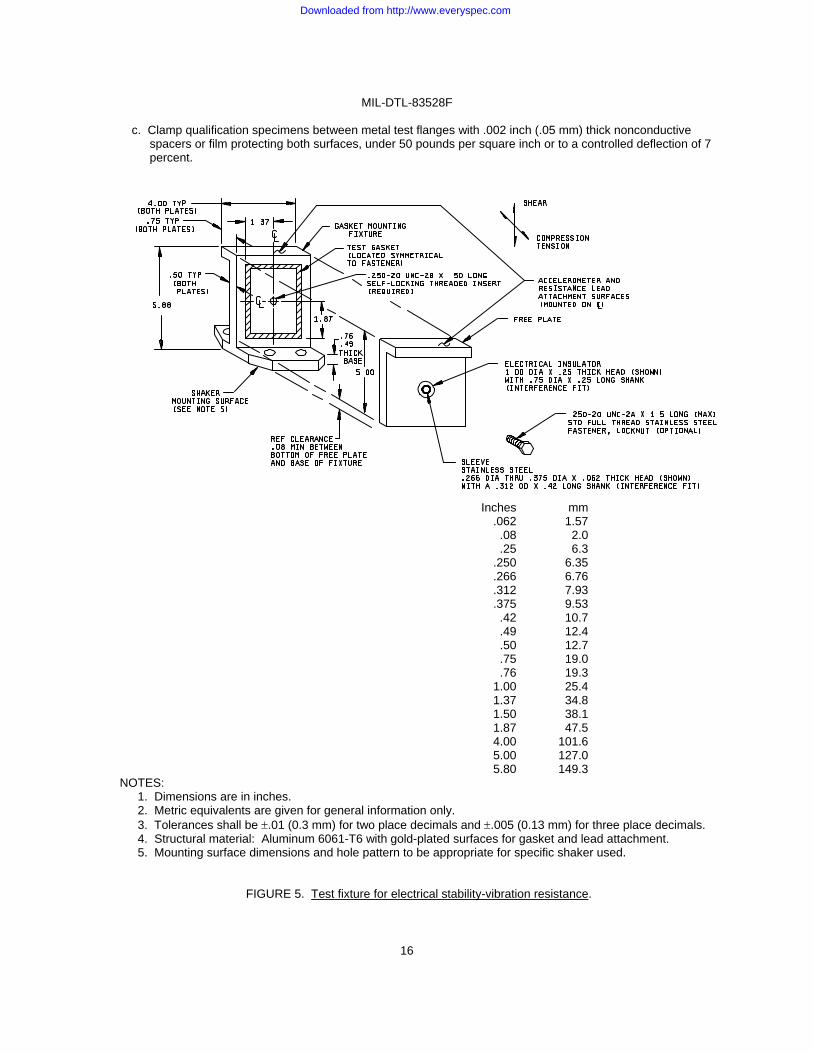
3.75 ±.030 in (95.3 ±.0.76 mm), a .15 ±.020 in (3.81 ± 0.51mm) width on all four sides, and a thickness of .062 ±.007 in (1.57 ± 0.18 mm). Mount the sample on the flange of an aluminum test enclosure (see figure 5) instrumented with input/output accelerometers. Flange and cover surfaces shall have a 32- to 63-microinch surface finish and shall be gold-plated over nickel. Apply a closure force on the gasket sample sufficient to deflect the gasket 5 to 10 percent. This deflection must be maintained throughout the test procedure. Apply this force by mounting the free plate to the fixture with a centrally located fastener, electrically insulated from the contact surfaces. A locknut may be used with the fastener to prevent loosening. Compression stops shall not be used be used.
b. Mount the test enclosure on a vibration shaker such that the plane of the gasket sample is parallel to the
axis of excitation (shear dynamic force on sample). The axis of excitation shall be in a vertical direction. c. Using a milliohmmeter with a sensitivity to 0.01 milliohm, measure the dc resistance in ohms from the cover
to the enclosure flange, through the gasket sample, and calculate the sample's initial volume resistivity (see 4.5.10.5). Net resistance of the sample gasket must be used for calculating volume resistivity. Net resistance is obtained by subtracting a blank reading from the test resistance reading, where the blank reading is taken through the assembled fixture at rest with no sample or compression stops in place. The contacting surfaces of the fixture must be thoroughly cleaned before taking the blank reading.
d. Search for resonant frequencies with a 10 g peak-to-peak acceleration input, sweeping from 200 to 1,000
Hz at a rate of 2 octaves per minute. Select the lowest frequency resonance. Let dwell for one minute at an input acceleration of 10 g peak-to-peak and then measure and record output acceleration (for reference only) in g's (peak-to-peak), and electrical resistance. The acceleration measurement shall be made parallel to the axis of excitation. After this, stop vibration and allow 30 seconds to elapse. Measure and record electrical resistance at rest. Calculate volume resistivity (see 4.5.10) from the highest resistance measured while under each condition.
NOTE: Resonance is defined as acceleration amplification between fixed and free plates of at least two to one (i.e., output acceleration > 2x input acceleration).
4.5.14 Low temperature flex. The low temperature flex of the material shall be determined using procedures and test specimens in accordance with ASTM D1329. Only temperature recovery levels TR10 and TR70 need be determined (see table I).
4.5.15 Life testing (heat aging). A heat aging test shall be accomplished for both qualification and quality
conformance acceptance in the following manner:
a. Specimens for testing shall be .5 in (12.7 mm) by 3 in (76.19 mm) by .055 in (1.40 mm) to .120 in (3.05 mm) (.027in (0.69 mm) to .005 in (0.13 mm) for type G) thick for qualification. Actual parts shall be used for quality conformance.
b. Check and record volume resistivity (see 4.5.10 for qualification and 4.5.11 for group A).
Downloaded from http://www.everyspec.com
MIL-DTL-83528F
16
c. Clamp qualification specimens between metal test flanges with .002 inch (.05 mm) thick nonconductive spacers or film protecting both surfaces, under 50 pounds per square inch or to a controlled deflection of 7 percent.
NOTES: 1. Dimensions are in inches. 2. Metric equivalents are given for general information only. 3. Tolerances shall be .01 (0.3 mm) for two place decimals and .005 (0.13 mm) for three place decimals. 4. Structural material: Aluminum 6061-T6 with gold-plated surfaces for gasket and lead attachment. 5. Mounting surface dimensions and hole pattern to be appropriate for specific shaker used.
FIGURE 5. Test fixture for electrical stability-vibration resistance.
Inches mm .062 1.57 .08 2.0 .25 6.3
.250 6.35
.266 6.76
.312 7.93
.375 9.53 .42 10.7 .49 12.4 .50 12.7 .75 19.0 .76 19.3
1.00 25.4 1.37 34.8 1.50 38.1 1.87 47.5 4.00 101.6 5.00 127.0 5.80 149.3
Downloaded from http://www.everyspec.com
MIL-DTL-83528F
17
d. Temperature.
(1) Heat for 1,000 hours at maximum operating temperature (see table I) ±5°C (flanged condition) for qualification.
(2) Heat for 48 hours at 1.25 times maximum operating temperature ±5°C (unflanged condition) for quality
conformance. e. Remove samples from oven and unclamp (qualification samples). Allow one hour for cooling. f. Rinse in isopropyl alcohol and dry for one hour minimum. g. Recheck volume resistivity as in step b.
4.5.16 EMP survivability. The EMP survivability of the material shall be determined using the following
equipment, specimens, and procedures. 4.5.16.1 Equipment.
a. Hybrid electromagnetic pulse (HEMP) current injection simulator, modified pulsed electron beam accelerator or capacitive discharge pulser, or equivalent, capable of driving a 9-kiloampere peak-to-peak dampened sinusoidal current pulse with a frequency of 1 to 1.5 megahertz and a decay time of 500 to 1,300 nanoseconds respectively, through the test gasket.
b. Current monitor (64-milliohm current-viewing resistor) to measure the current driven through the test
gasket. c. High speed data acquisition system oscilloscope with a camera (or equivalent), to record current pulse
driven through the test gasket. d. Four-probe resistance measuring system milliohm meter suitable for measuring pre-test and past-test
resistance of test gaskets, capable of measuring resistances of 1 milliohm.
4.5.16.2 Specimens and preparation. The test gaskets shall be .062 inch (1.57 mm ) thick, .070 inch (1.78 mm) wide rectangular cross section washers with a 3.00 (76.20 mm) ±.02 inch (0.51 mm) mean diameter die cut from sheet stock. The test gasket will be clamped between two clean tin-plated aluminum plates, using insulating fasteners, with sufficient force to deflect the gasket 10 percent. The test gasket will not be disturbed (clamping force wilt not be increased) until the post-test resistance has been measured. Prior to testing, inspect the electrodes for spots where the tin plating maybe burned through and corrosion started. Clean or replate as needed.
4.5.16.3 Test procedures.
a. After the test gasket is installed in the HEMP current injection simulator, the simulated HEMP current, 9-kiloampere peak-to-peak with a frequency of 1 to 1.5 megahertz and a decay time of 500 to 1,300 nanoseconds, will be driven through a test gasket. This current pulse will be recorded with a fast oscilloscope.
b. Following the simulated HEMP current pulse, and without disturbing the test gasket, measure and record
the post-test resistance of the test gasket. Calculate the post-test volume resistivity from the measured resistance:
Downloaded from http://www.everyspec.com

MIL-DTL-83528F
18
=
Where:
- is the DC volume resistivity in ohm-cm. R - is the measured resistance in ohms. A - is the contact surface area of probe (cm2). L - is the thickness of specimen (cm).
c. If the post-test volume resistivity has not increased above the limit (table I) for volume resistivity after EMP exposure, the sample shall be considered to have survived 0.9 kA/in EMP exposure.
4.5.17 Fluid immersion. The purpose of this test is to determine the ability of gaskets to resist degradation when
exposed to specific fluids with which the gaskets may come into contact during their service life. Degradation from this test and the performance limits are:
a. Swelling: Maximum volume swell of 25 percent. b. Softening: Maximum change in hardness of 15 shore A units.
4.5.17.1 Test equipment.
a. Pyrex beakers (one for each test fluid) or similar stainless vessels to contain the various fluids in a sufficient quantity to completely immerse gaskets.
b. An air circulating oven capable of maintaining temperature within ±3°C of required setting. The maximum test temperature is +175°C (347°F). c. Immersion temperature measuring device covering the range of 0°C to +200°C (32°F to 392°F).
d. Table stoves or hot plates.
e. Unless otherwise specified, test fluids shall be in accordance with table VII. The fluids listed represent
those in wide general use. When other special fluids are required, the test temperature shall be at least +10°C below the fluids' flash point.
R A L
Downloaded from http://www.everyspec.com
MIL-DTL-83528F
19
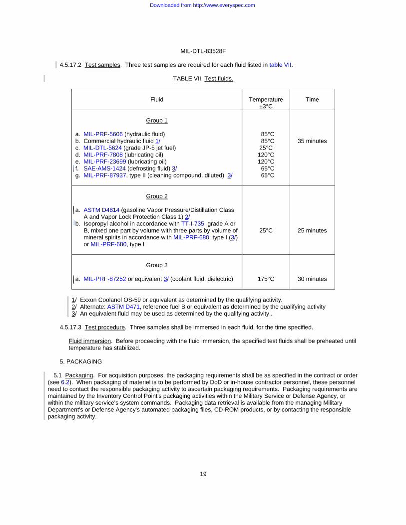
4.5.17.2 Test samples. Three test samples are required for each fluid listed in table VII.
TABLE VII. Test fluids.
Fluid
Temperature
±3°C
Time
Group 1
a. MIL-PRF-5606 (hydraulic fluid) b. Commercial hydraulic fluid 1/ c. MIL-DTL-5624 (grade JP-5 jet fuel) d. MIL-PRF-7808 (lubricating oil) e. MIL-PRF-23699 (lubricating oil) f. SAE-AMS-1424 (defrosting fluid) 3/ g. MIL-PRF-87937, type II (cleaning compound, diluted) 3/
85°C 85°C 25°C
120°C 120°C 65°C 65°C
35 minutes
Group 2
a. ASTM D4814 (gasoline Vapor Pressure/Distillation Class
A and Vapor Lock Protection Class 1) 2/ b. Isopropyl alcohol in accordance with TT-I-735, grade A or
B, mixed one part by volume with three parts by volume of mineral spirits in accordance with MIL-PRF-680, type I (3/) or MIL-PRF-680, type I
25°C
25 minutes
Group 3
a. MIL-PRF-87252 or equivalent 3/ (coolant fluid, dielectric)
175°C
30 minutes
1/ Exxon Coolanol OS-59 or equivalent as determined by the qualifying activity. 2/ Alternate: ASTM D471, reference fuel B or equivalent as determined by the qualifying activity 3/ An equivalent fluid may be used as determined by the qualifying activity..
4.5.17.3 Test procedure. Three samples shall be immersed in each fluid, for the time specified.
Fluid immersion. Before proceeding with the fluid immersion, the specified test fluids shall be preheated until temperature has stabilized.
5. PACKAGING
5.1 Packaging. For acquisition purposes, the packaging requirements shall be as specified in the contract or order (see 6.2). When packaging of materiel is to be performed by DoD or in-house contractor personnel, these personnel need to contact the responsible packaging activity to ascertain packaging requirements. Packaging requirements are maintained by the Inventory Control Point's packaging activities within the Military Service or Defense Agency, or within the military service's system commands. Packaging data retrieval is available from the managing Military Department's or Defense Agency's automated packaging files, CD-ROM products, or by contacting the responsible packaging activity.
Downloaded from http://www.everyspec.com

MIL-DTL-83528F
20
6. NOTES
(This section contains information of a general or explanatory nature that may be helpful, but is not mandatory.)
6.1 Intended use.
6.1.1 General. Gaskets covered by this specification are designed to provide EMI/RFI shielding, EMP survivability, and environmental protection for electronic enclosures, connectors, and waveguides. Their principal areas of application are aircraft, missiles, spacecraft, and ground support equipment. This does not preclude the use of these gaskets in other military applications.
6.1.2 Salt spray environments. All EMI gasket materials (metal and elastomer) to varying degrees are incompatible with certain flange surfaces. Design of the joint, therefore, plays a central role in determining the electrical stability and corrosion resistance of the joint. Design variables include: Flange material and finish, gasket filler and form (sheet, O-ring in a groove), use of parallel nonconductive environmental gaskets, mechanical design, and use of insulating coatings. Choice of the design options should depend on: Environment of the application, levels of shielding effectiveness required versus frequency, and expected life of the equipment. When designing for salt spray environments, all of the preceding factors must be considered.
6.1.3 Vibration environments. Type M material may be suitable for high-frequency vibration applications.
6.1.4 Shielding effectiveness. IEEE-STD-299 has been considered an acceptable method for determining shielding effectiveness as modified and supplemented by figure 4. 6.2 Acquisition requirements. Acquisition documents should specify the following: Title, number, and date of the specification.
6.2.1 Items covered by specification sheets. Acquisition documents for gaskets covered by MIL-DTL-83528 specification sheets should specify the following:
a. Title, number, and date of this specification.
b. Title, number, and date of the applicable specification sheet and the complete PIN (see 1.2.1 and 3.1). c. Levels of preservation and packing required (see 5.1). d. Special or additional marking (if required) (see 5.1). e. Length (if required) (see 3.1).
Downloaded from http://www.everyspec.com
MIL-DTL-83528F
21
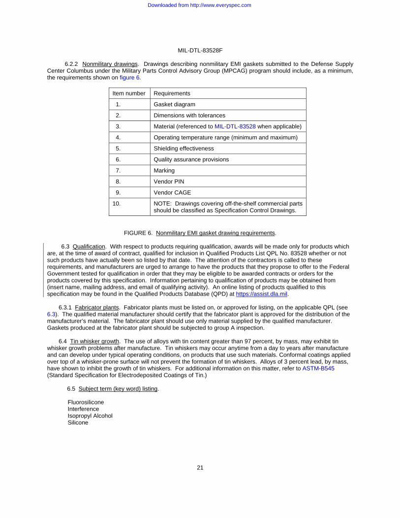
6.2.2 Nonmilitary drawings. Drawings describing nonmilitary EMI gaskets submitted to the Defense Supply Center Columbus under the Military Parts Control Advisory Group (MPCAG) program should include, as a minimum, the requirements shown on figure 6.
Item number Requirements
1. Gasket diagram
2. Dimensions with tolerances
3. Material (referenced to MIL-DTL-83528 when applicable)
4. Operating temperature range (minimum and maximum)
5. Shielding effectiveness
6. Quality assurance provisions
7. Marking
8. Vendor PIN
9. Vendor CAGE
10. NOTE: Drawings covering off-the-shelf commercial parts should be classified as Specification Control Drawings.
FIGURE 6. Nonmilitary EMI gasket drawing requirements. 6.3 Qualification. With respect to products requiring qualification, awards will be made only for products which are, at the time of award of contract, qualified for inclusion in Qualified Products List QPL No. 83528 whether or not such products have actually been so listed by that date. The attention of the contractors is called to these requirements, and manufacturers are urged to arrange to have the products that they propose to offer to the Federal Government tested for qualification in order that they may be eligible to be awarded contracts or orders for the products covered by this specification. Information pertaining to qualification of products may be obtained from (insert name, mailing address, and email of qualifying activity). An online listing of products qualified to this specification may be found in the Qualified Products Database (QPD) at https://assist.dla.mil. 6.3.1 Fabricator plants. Fabricator plants must be listed on, or approved for listing, on the applicable QPL (see 6.3). The qualified material manufacturer should certify that the fabricator plant is approved for the distribution of the manufacturer’s material. The fabricator plant should use only material supplied by the qualified manufacturer. Gaskets produced at the fabricator plant should be subjected to group A inspection.
6.4 Tin whisker growth. The use of alloys with tin content greater than 97 percent, by mass, may exhibit tin whisker growth problems after manufacture. Tin whiskers may occur anytime from a day to years after manufacture and can develop under typical operating conditions, on products that use such materials. Conformal coatings applied over top of a whisker-prone surface will not prevent the formation of tin whiskers. Alloys of 3 percent lead, by mass, have shown to inhibit the growth of tin whiskers. For additional information on this matter, refer to ASTM-B545 (Standard Specification for Electrodeposited Coatings of Tin.)
6.5 Subject term (key word) listing.
Fluorosilicone Interference Isopropyl Alcohol Silicone
Downloaded from http://www.everyspec.com
MIL-DTL-83528F
22
6.6 Storage. Material should be stored in sealed polyethylene when possible; otherwise, it should be stored in such a way that it is not exposed to sulfur. Sulfur-cured materials or materials containing sulfur based plasticizers (such as most neoprenes) should not be stored in close proximity to materials covered by this specification. When stored between 50°F to 90°F, in cabinets, bins or any other storage container which prevents excessive exposure to light, and in the absence of sulfur, the shelf life should exceed 15 years.
6.7 Definitions.
6.7.1 Conductive elastomer EMI gaskets. Conductive elastomer gaskets are highly electrically conductive,
mechanically resilient and conformable vulcanized gaskets which provide low interface resistance between mating electronic enclosure flanges or covers while simultaneously providing moisture, pressure, or environmental sealing. They are available in the following types:
a. Flat gaskets (die cut from sheets). b. Molded seals (such as O-rings or other profiles). c. Extruded or molded strips (which may be spliced into rings or other fabricated shapes). d. Waveguide gaskets.
6.8 Environmentally preferable material. Environmentally preferable or biobased materials should be used to the maximum extent possible to meet the requirements of this specification. As of the dating of this document, the U.S. Environmental Protection Agency (EPA) is focusing efforts on reducing 31 priority chemicals. The list of chemicals and additional information is available on their website at http://www.epa.gov/osw/hazard/wastemin/priority.htm. Included in the list of 31 priority chemicals are cadmium, lead, and mercury. Use of these materials should be minimized or eliminated unless needed to meet the requirements specified herein (see Section 3).
6.9 Changes from previous issue. The margins of this specification are marked with vertical lines to indicate where changes from the previous issue were made. This was done as a convenience only and the Government assumes no liability whatsoever for any inaccuracies in these notations. Bidders and contractors are cautioned to evaluate the requirements of this document based on the entire content irrespective of the marginal notations and relationship to the previous issue.
Custodians: Preparing activity: Army - CR DLA - CC Navy - EC Air Force - 85 (Project 5999-2015-012) DLA - CC Review activities: Air Force - 19, 99 NOTE: The activities listed above were interested in this document as of the date of this document. Since organizations and responsibilities can change, you should verify the currency of the information above using the ASSIST Online database at https://assist.dla.mil/.
Downloaded from http://www.everyspec.com