In this issueihpva.org/HParchive/PDF/40-v12n1-1995.pdfSteering The steering geometry is conventional...
24
Transcript of In this issueihpva.org/HParchive/PDF/40-v12n1-1995.pdfSteering The steering geometry is conventional...

Human PowerThe technical journal of the
International Human-Powered VehicleAssociation
David Gordon Wilson, editor21 Winthrop Street
Winchester, MA 01890-2851, USAPhones: 617-729-2203 (home)
617-253-5121 (MIT); 617-258-6149 (FAX)dgwilson(mit.edu (email)
Associate editorsToshio Kataoka, Japan
1-7-2-818 Hiranomiya-MachiHirano-ku, Osaka-shi, Japan 547
Theodor Schmidt, EuropeOrtbiihlweg 44
CH-3612 Steffisburg, SwitzerlandPhilip Thiel, watercraft
4720 7th Avenue, NESeattle, WA 98105, USA
IHPVAP.O. Box 51255
Indianapolis, IN 46251, USAPhone: 317-876-9478; FAX: 317-876-9470
OfficersMarti Daily, president, exec. director
Adam Englund, secretaryTess Machlin, treasurer
Paul MacCready, int'l presidentNancy Sanford, VP waterAndrew Letton, VP land
Chris Roper, VP airMatteo Martignoni, VP ATV
Theodor Schmidt, VP hybrid powerBoard members
Leonard BrunkallaMarti Daily
Murray DowlingBill GainesAl KrauseChet Kyle
Andrew LettonGardner MartinDennis Taves
Human Power is published approx.quarterly by the International Human-Powered Vehicle Assoc., Inc., a non-profitorganization devoted to the study and ap-plication of human muscular potential topropel craft through the air, in and on thewater and on land. Membership informa-tion is available by sending a self-addressed stamped business-sized enve-lope to the IHPVA address above.
Additional copies of Human Power maybe purchased by members for $3.50 each,and by non-members for $5.00 each.
Material in Human Power is copyrightedby the IHPVA. Unless copyrighted alsoby the author(s), complete articles or rep-resentative excerpts may be publishedelsewhere if full credit to the author(s) andthe IHPVA is prominently given.
We welcome contributions, preferablyon a PC diskette, for Human Power. Sendthem to the editor at his address above.He would be happy to send guidelines onpreparing contributions. They should beof technical or longer-term interest: newsand notices etc. should go to HPV Newseditor Leonard Brunkalla at 260 S. Chan-ning, apt. 1, Elgin, IL 60120-6619.
We are indebted to the authors and toMarti Daily and her volunteers, whosededicated help made this issue possible.Dave Wilson
In this issue
Rowing-action bicycles:success and uncertainty
Two contrasting reports leadoff this issue: an apparently highlysuccessful rowing-action bicyclewith which Derk Thijs won theParis-Amsterdam race; and the re-cently introduced commercial Row-bike of Scott Olson (p. 3).
Recumbent tricycle design
Allen Armstrong, a highlyskilled electro-mechanical engineer,applies classical design methods toa recumbent tricycle. The drawingsand photographs are beautiful(p. 5).
Systems design of theDragonfly: a human-powered helicopter
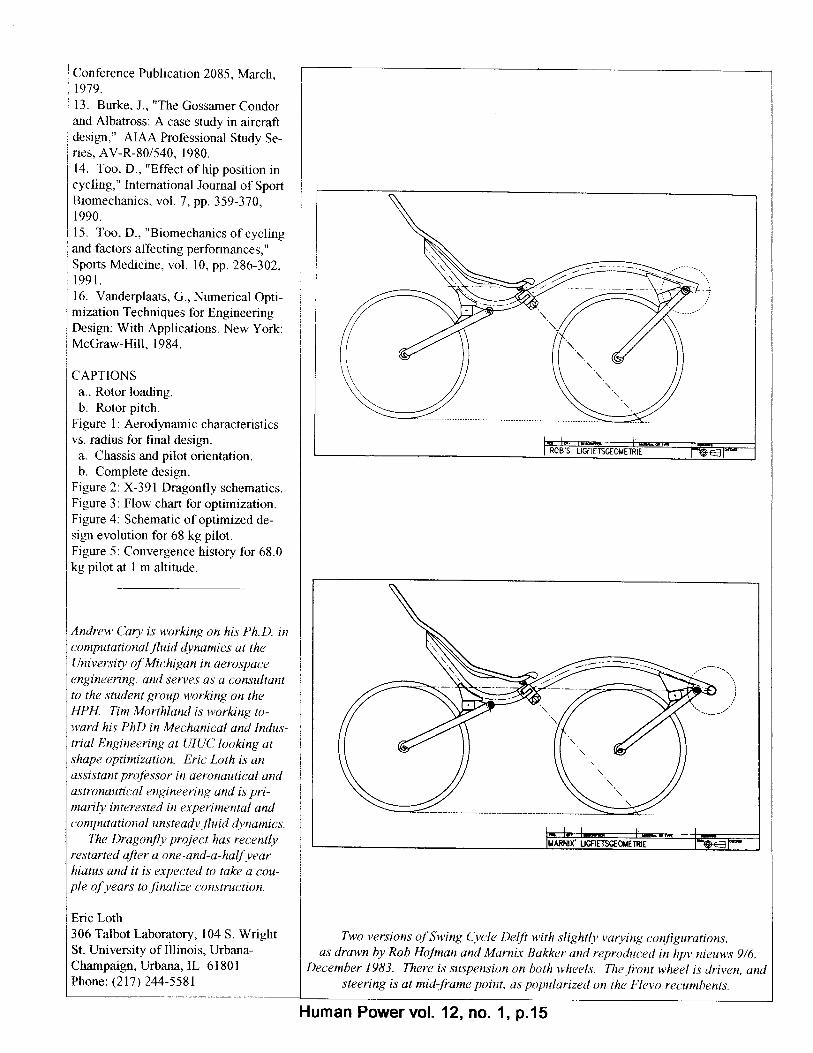
The most difficult-to-reachprize in the human-power field isthat set by the American HelicopterSociety to honor Igor Sikorsky. Ateam from the University of Illinoisled by Eric Loth describes the ap-plication of precise systems engi-neering to the optimization study.This predicts that the goal is attain-able, and the two-rotor HPH is cur-rently being constructed. (p. 9).
Octogenarian bicyclist
Ron Beams begins his story - ofsomeone who came late to bicy-cling, and who designed his ownrecumbent tricycles. He rides themin the company of others who findthat bicycling keeps them enjoyinglife long after many couch potatoeshave given up (p. 16).
Shaft drive in theDaedalus aircraft: why
there and not in HP landvehicles?
Jean-Joseph Cote, who put in agreat many hours on the HP aircraftthat flew 119 km, responds to youreditor's question: if here, why noton all HPVs? (p. 21).
Letters - on AHPVs
Assisted HPVs continue to at-tract a lot of comment. John Tetzre-iterates his principles of AHPVs.and believes that a recent paper inHuman Power could have been de-scribing electrically powered vehi-cles. Theo Schmidt issues a pleafor agreement on AHPVs so thatthey may be included in our races,and so lead to improvements. PeterErnst would like to see Stirling en-gines developed for AHPVs (p. 17).
Reviews
A labor of love is onedescription of Tony Hadland's newbook on the "space-frame Moul-tons". Also reviewed by your editoiis a book on a remarkable tour ofthe U.S. by a Dutch couple, on tworecumbent bicycles. These weredesigned and built by the husband,while the story, "Pedalling un-known paths", is told by his spouse,Michele Velthuizen de Vries. Thelatest buyers' guide from Recum-bent Cyclist News and a Britishmagazine "Cycling today" are alsoreviewed. (pp. 15 & 20)
Correction
Your editor unwittingly cut offa large, valuable part of a table oncoast-down tests giving compara-tive aerodynamic-drag data for dif-ferent vehicles reported by MartinStaubach in his paper "The unfairadvantage". The whole table isgiven here (p. 22).
Editorials
There are similarities betweenthe IHPVA and surfing associa-tions, and we could learn fromthem. A Toyota house magazine isdevoted entirely to a favorable dis-cussion of HPVs. The somewhatuncertain frequency of publicationof Human Power is partly blamedon the extraordinary uncertainty of"promising" contributors. Theseare the two topics in the editorialson p. 23.
Dave Wilsoi
Human Power, vol. 12, no. 1, spring 1995, p.2
-
I


idlers, machined from nylon #40 indus-trial sprockets (Stock Drive Products,New Hyde Park, NY) divert the chainunder the seat-adjusting clamp. Clear-ance is so limited there that the chainsmust run side-by-side. It should havebeen no surprise that chains under ten-sion want to be as straight as possible:they don't like being diverted, and thus(particularly when going over bumps)find ingenious ways to get free of theiridlers. Keeping them in their place hasrequired large teeth on the idler sprock-ets, and auxiliary idlers (non-load-bearing) made from derailleur jockeypulleys.
Clipless pedals are an invaluable aidin keeping the feet on recumbent pedals.In the TRYK, there's no need to detach atstops, and so they become veryconvenient.
SteeringThe steering geometry is conventional
Ackerman (wherein the steering-armjoints lie on a line between the kingpinand the center of the rear axle). Thisprovides for the inside wheel following atighter radius in turns than the outer.Camber is 0°, and kingpin inclination 12°
giving a scrub radius of 18.6mm (0.73inch). Caster is 10°, giving a caster trailof 38.6 mm (1.52 in.). The 12.7-mmkingpins (an inverted LeMoine design,see fig. 4) are machined in unit with theaxle mount from 1020 steel, and thesteering arms TIG-welded on, taking carenot to overheat the steel in the highlystressed junction area. A centrally piv-oted bell crank relays the motion of thelongitudinal drag link (which is adjustedfor length when the seat is moved) to thelateral tie rods through aircraft ball-rodends. At the handlebar end, the attach-ment is movable to adjust the steeringratio. A ratio close to unity seems aboutright.
PerformanceMy expectation that reduced frontal
area would lead to an improvement inall-around performance (compared to anupright bicycle) has not been met. TheTRYK is better aerodynamically, but itsweight of 17.3kg and the recumbentposition slow it on hills. On a free-rolling test down a local hill, the TRYKwould reach 16.3 m/s (58.7 km/h,
36.5mph), where a road-racing uprightbicycle reached 14.3 m/s. However, go-ing uphill, the TRYK fell behind, 3.1 m/sto 4.9 m/s. On a 30-km (18.5-mile) com-mute, the hill effect, and, probably, therolling-resistance penalty of the extrawheel mentioned by Whitt and Wilson3
combine to increase its trip time from 1 heven to I h 10 m. Since traffic and windconditions vary from day to day, thecommute-time comparison may have afive-minute error, but these numbers rep-resent the best of perhaps eight trips oneach vehicle. For my particular com-mute, the TRYK's increased comfort justabout balances the upright's increasedspeed, and I've found I enjoy alternatingbetween one and the other to keep thetrip enjoyable.
Visibility on the road is an issue withlow recumbent vehicles of this type. Toincrease it, I use a flag, inserted in theleft seatback tube. I commute in heavysuburban traffic. In 1500 km of riding, Ihave had no close calls, and thus no visi-bility problem that I can report, althoughthere are drivers who think I shouldn't besharing their road space, and let meknow in a limited variety of unprintableways! Fortunately, for each one of them,there are a fair number of others giving adelighted thumbs up.
As mentioned previously, tip-over sta-bility is less than absolute. I have tippedover on two occasions, each time withoutinjury, as the distance to the ground isshort. Leaning into corners is good in-surance in negotiating fast, sharp comers,but might not be done in an emergencymaneuver, so there is some reason to becareful.
A fairing has not been planned, be-cause its effect of improving speeddownhill at the expense of extra weightgoing up does not seem an advantage inmy usage pattern. Suspension was notincluded for much the same reason: themesh seat and resilient frame boom takesome of the shock out of bumps, and rideimprovement at the cost of extra weightwould be undesirable.
ConclusionThe project's general goals of com-
fort, stability, utility and durability havebeen met. I believe, all things consid-ered, the TRYK is safer than a bicycle,but this is a very subjective judgment. It
is certainly much more comfortable. Thecost of construction, about $1400 not in-cluding some machining I had done pro-fessionally to save time, has been worthit, just for the feeling of speeding downthe bike trail in a miniature formula car!
References1. Raine, J.K. and Amor, M.R., (1991)MODELING ENERGY CONSUMP-TION ON THE TRICANTER HPV, Hu-man Power vol. 9/3 & 9/4 pp.26-33.2. Ballantine, R. and Grant, R. (1992)RICHARDS' ULTIMATE BICYCLEBOOK. New York: Dorling Kindersley.pp 128-131, an excellent photo of MikeBurrows' Windcheetah.3. Whitt, F.R. and Wilson, D.G. (1982)BICYCLING SCIENCE. Cambridge:MIT Press. p. 171.4. (1993) THE TRICE RECUMBENTTRIKE, Recumbent Cyclist News #16.p.3.5. (1992) THE THEBIS 201 TOURINGTRIKE, Recumbent Cyclist News #10,p.1.
Allen Armstrong, 34 Robinson Road,Lexington, MA 02173, USAPhone: (617-861-0029)e-mail: alarmstroaaol.com.
Allen Armstrong is a mechanical engi-neer who designs focused-ion-beamsemiconductor-manufacturing equip-ment. He invented the Positech indexingderailleur and, with David Gordon Wil-son, the Positech wet-weather caliperbrake.
Human Power vol.12 no.1, p.81
--

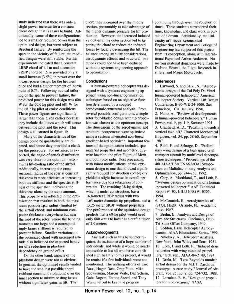
AbstractA human-powered helicopter was
designed using non-linear-optimizationtechniques based on an objective func-tion determined by a coupledaerodynamic-structural discretizedanalysis. The structural analysis pre-dicted local stresses and rotor deflec-tion, which were iteratively used todetermine the radial ground-effect dis-tribution and the total aerodynamicforces. This systems-engineering de-sign procedure allowed a cohesivemethodology that permitted detailedand automated tradeoff decisions. Thebest overall configuration was deter-mined to be a combination of two dif-ferent blade pairs on a single shaft withtip propellers on one of the blade pairsin order to achieve a stable and power-efficient design. All essential structuraland aerodynamic design parameters ofthe configuration were simultaneouslyintroduced as either variables orbounded constraints for the non-lineargradient-based optimizer which mini-mized the power required for a 68-kgpilot to hover at a craft altitude of twometers. The performance calculation ofthe optimized design predicts that only680-watts are required to hover at thiscondition.
IntroductionThe motivation for the present study
is the Igor Sikorsky prize, established in1980 by the American Helicopter Soci-ety, which will be awarded to the firsthuman-powered helicopter (HPH) thatreaches a height of 3 meters during aone-minute hover flight. Human-powered-helicopter designs have bor-rowed extensively from their fixed-wingcounterparts, and while approximately17 HPHs have been constructed interna-tionally, only two have achieved docu-mented flight: the CaliforniaPolytechnic State University--San LuisObispo's (Cal Poly) Da Vinci III in 1989and, more recently, Naito's Yuri I in1993. Each of these craft, after nearly a
decade of development, hovered at analtitude of about 0.2 meters for a fewseconds. The Da Vinci III employed aunique rotor-tip propeller propulsion sys-tem which eliminated the need for acounter-torque device (ref. 1). A station-ary chassis was suspended by bearingsfrom the two rotor blades, which rotateddue to the aerodynamic force created bypropellers at the rotor tips. While asmall degree of chassis rotation, on theorder of one RPM, is inevitable due tobearing friction, the result is an efficientand lioht-weiohtdrive system. Theflight video indi-cated several insta-bilities, with themost notable beingan uncontrolledrolling motion.This was the reasonfor the flight termi-nation (after eightseconds), as op-posed to the expira-tion of pilot poweror to structural fail-ure. Therefore,stability and controlare also importantaspects of a suc-cessful HPH design.The Yuri I was aradically differentconcept developedby Akiro Naito ofJapan that employsfour separate rotors,-- - - - -_ -1 _~ _;V4;,U I.lt4LVU ti 4
10-meter radius from the pilot andsis at 90-degree intervals. The sucflight attempt in the fall of 1993 le5.5-second hover.
Previous HPH research includeNaito's Papillon designs (ref. 2) anCranfield's Vertigo design (ref. 3).Vertigo project in England emplo)counter-rotating blades and was piily unsuccessful due to the dynamithe rotor-blade combination. The Iover the lower rotor blade separat{
during rotor crossover, leading to bladefatigue and craft instability.
The design of the UIUC project, theX-391 Dragonfly, was started in 1990and employed the following basic meth-odology: 1) determine the best overallconcept, 2) develop subsystem analysismethods, 3) optimize the entire designusing systems engineering with non-linear gradient-based methods, and 4)perform small design changes to mini-mize construction complications. Eachof these phases is summarized in this pa-per, with reference to construction tech-niques only as they affect the designprocess.
Systems engineering combines sev-eral engineering disciplines in the designprocess to create a product that satisfies
(a) Chassis and pilot orientation
(b) Complete designFigure I X-391 Dragonfly schematics
all of the requirements while optimizinga set of parameters. In the aerospaceindustry, these disciplines can includestructures, aerodynamics, dynamics, pro-pulsion, and manufacturing and represena wide variety of constraints and analy-ses. By combining these into a singleanalytic description of the craft perform-ance, as was done in this study, a moreeffective optimization of the design maybe achieved. This technology is oftenreferred to as Multi-Disciplinary Optimi-zation. Rohl and Schrage (ref. 4)
Human Power vol. 12, no. 1, p.9
Systems design of the Dragonfly:a human-powered helicopter
byAndrew Cary, Tim Morthland and Eric Loth
.
l
- s-to H v-~Y1
"" ' 1 ' A A

categorize multilevel decompositiontechniques as sequential (evaluatethrough further refinements), parallel(evaluate subsystems simultaneously),and hybrid. The latter approach is usedherein, with a preliminary design analy-sis being used to establish the best over-all configuration and initial parameterestimates, followed by a level of paral-lel inter-related subsystem analyses tofinalize the theoretical optimization.For the parallel optimization of the pre-sent study, the aerodynamics and struc-tures were integrated for a simultaneoussubsystem optimization, while the dy-namics, propulsion, and fabrication is-sues were incorporated throughempirical models and systemconstraints.
Configuration identificationIn order to optimize the craft design,
the general configuration must first beselected. This selection itself involveda crude optimization of several candi-date designs by estimating likely craftweights and propulsive efficiencies.Since estimates of the rotor diameteryielded values as large as 30 meters fora single pilot, it was assumed that theincreased size dictated by employingmultiple pilots, as well as the complex-ity of assuring a uniform distribution ofpower production, made a two-personcrew impractical. To preserve staticstability, it was also assumed that thepilot, who will constitute the majorityof the mass, would be under the rotordisk plane.
Several ideas for basic configura-tions that resolved the anti-torque re-quirements imposed by the use of arotor system were considered, of whichonly five concepts seemed likely: a con-ventional tail-rotor design; a tip-propeller driven rotor design, e.g. DaVinci III; two concentric counter-rotating rotors, e.g. Vertigo; two ormore counter-rotating rotors displacedfrom each other, e.g. Yuri I; and a duct-based ground-effect machine using ei-ther counter-rotating propellers or amultiple duct system. Each of thesecandidate concepts was then designedbased on an average flight altitude of1.5 meters to allow a direct comparisonof the power required to hover. Thisincluded estimation of such items as
component weights, ground effect, pro-peller efficiency, and properties of ad-vanced materials, as well as the use ofrotor-disk theory and a cantilever-beammodel (ref. 5).
The weight of the long rigid spar(s)necessary for the tail-rotor design or thedisplaced counter-rotating design wasfound to render these designs inferior dueto the insufficient compensation in pro-pulsive efficiency. For the conventionalrotor, an additional disadvantage is thediversion of more than 5% of thehuman power for the non-lifting tail ro-tor. These additional spars are not neces-sary on the tip-driven design. Theconcentric-shaft counter-rotating ideawas eliminated due to power losses asso-ciated with rotor overlap and due to con-cerns of dynamic interference similar tothose experienced by the Vertigoproject. The most reasonable of theduct-based ground-effect machines interms of stability and efficiency is aquadruple-duct peripheral-jet design (ref.6). While theoretical thrust augmenta-tions for ground-effect machines can besignificant at low altitudes, power lossesof the fan and ducting yield an overallpoor efficiency. Therefore, based onquantitative evaluation of the above con-figurations, the tip-driven design wasfound to be superior to the extent thatfurther optimization was limited to thisone design. This superiority was due tothe minimal increasein mass associatedwith resolution ofthe counter-torqueproblem, potentiallyhigh efficiency ofthe rotor, overallsimplicity, andproven success. Ef-ficiency compari-sons by Naito (ref.2) support this con-clusion. A craftwith a 15-m rotorradius was estimatedto weigh 117 kgwith pilot and to re-quire only 470 wattsto hover at 1.5 m.
It is believed thatthe dynamic insta-bility of the DaVinci III stemmed
from the small moment of inertia aboutthe spar axis that allowed an unbalancedoverturning moment to produce a signifi-cant angular acceleration. Additionally,due to the angular momentum of thelarge rotors, precession can lead to dy-namic stability difficulties if there is anunbalanced moment on the craft. Tocounter these stability problems, a sec-ond set of rotor blades was added withthe size of this pair determined by a bal-ance between power and dynamic con-cerns. This compromise resulted in alarge-radius blade pair (LRBP) and ashort-radius blade pair (SRBP).
Optimization methodologyBecause of the need to design a near-
optimal craft (i.e. maximum altitude fora power of about 600 W), it was believedthat a systems-engineering approachwould result in a craft superior to one inwhich individual subsystems were inde-pendently optimized. For instance, sparmass and deflection have strong influ-ences on the aerodynamic design of arotor blade which is then reflected in thestructural loading. By iterating betweena code which analyzed the rotor structur-ally and one that analyzed it aerodynamically, a prediction could be made of thepower required for a given helicopter de-sign to maintain a specified altitude. Us-ing estimated efficiencies for thetransmission system ( trans ) and the
START
DESIGN b' = New Design ParametersI nF1FTMITIN I
Figure 2 Flow chart for optimization
Human Power vol. 12, no. 1, p.10
- -

propellers (lprop ), the power requiredfrom the pilot could then be determined,
Protor. r-req.Ppilot = propl rons
This pilot power provided the designwith an objective function to comparedifferent variations of the design. Analternative approach would be to con-sider a fixed pilot output and seek themaximum altitude that a given designcould achieve, but such a search is morecostly. A brief description of the mod-els simultaneously used for the optimi-zation is given below, where importantdetails are given in Ref. 5.
Spar structural modelCarbon-fiber tubular spars with
Mylar-covered airfoil-shaped foam ribsare used for the rotor blades. Varyingthicknesses and orientations of unidirec-tional carbon-fiber pre-preg are laidover an aluminum mandrel of constantouter diameter. These carbon tubes arecured, removed from the mandrel, andjoined together to form the spars. Thestructural model was based on this con-struction and assumed that the foam andMylar would not influence rotor deflec-tion. Guy wires were used to add fur-ther stiffness to the LRBP with aminimal weight penalty. Using Euler-Bernoulli beam theory and the momentdistribution along the rotor span ob-tained from the aerodynamic analysis,the rotor deflection was determined.The Young's modulus and moment ofinertia about the z axis are functions ofthe rotor radius due to variations incarbon-fiber orientation, spar thickness,and spar-segment radius.
Modes of failure for bending stress,shear stress, and buckling were consid-ered in the structural analysis. Thebending stress, o r, was based on asymmetric beam. The shear-stress dis-tribution was obtained by dividing theshear flow of a homogeneous beam bythe local thickness of the cylindricalbeam. The onset of buckling was coIn-puted from a relation given by Bruhn(ref. 7). The required stresses were re-quired to satisfy the critical relation
(, ra) + _( ax J< 1.0 (1.0)
for combined shear and bending, where(rmax is the maximum allowable bending
stress, (Tb is the buckling stress, and
C b is the maximum allowable buck-ling stress.
In addition to providing a viable spardesign, this analysis yields rotor deflec-tion and spar weights that are required bythe aerodynamic analysis.
Rotor aerodynamic modelThe primary aerodynamic model de-
termined the thrust required for the craftby summing the component weights andapplying an acceleration factor reflectingthe craft's vertical acceleration. Usingthe thrust and an analytically determinedblade lift coefficient, the rotor angularvelocity could be determined. Since theblade lift coefficient involved terms con-taining the rotor angular velocity, itwas necessary to solve the system itera-tively. The resulting solution containedinformation used to determine the localloading of the spar and the power re-quired to maintain the specified flightcondition, which were required by theother subsystem models.
The blade lift coefficient was deter-mined from the planform and the angle-of-attack distribution. This resulted infewer iterations than specifying the pitchdistribution and provided more directcontrol in shaping the aerodynamic char-acteristics of the rotor. The pitch couldlater be determined from the induced-velocity distribution. The induced veloc-ity was represented as the superpositionof three factors: local loading, propellerwash, and ground effect. The local load-ing contribution was determined from themodified blade-element theory by equat-ing the thrust at a local element to thatpredicted by the actuator-disk theory(refs. 8,9). The propeller wash was mod-eled as having solid-body rotation at thesame angular velocity as the propellerinside the propeller's radius and amatched irrotational flow exterior to it(ref. 10). The ground-effect model cho-sen consisted of a series of vortex rings:it was validated with data for ultra-lowrotor altitude (ref. 5).
The spar deflection obtained from thestructural model also plays a key role inthe ground-effect calculation since theupwash is a function of the lifting
element's local altitude. Additionally, itcauses the local blade element to rotateout of the rotor plane, changing the di-rection of the lift vector slightly, whichwas accounted for in the analysis.
This analysis could then be performedfor a given mass and planform distribu-tion. Finally, the power required tomaintain the specified flight conditionwas determined by integrating the para-sitic and induced-drag moment over allof the blades and adding the power re-quired to climb. The climb-power termindicates that the best flight profile maynot be to hover in high ground effect foras long as possible and to then "pop" uptoward the 3-meter goal, as this wouldresult in not only a large climb power,but also a reduction in the effective angleof attack due to the increased downwash.
Because the X-391 Dragonfly's rotoroperates in the low-Reynolds-numberregime, it was desired to find a rotor air-foil that was designed for a high lift-to-drag ratio in this range and that was alsotolerant to minor construction errors.These requirements led to the selectionof the DAE class of airfoils designed forthe Daedalus project by Mark Drela (ref.11). The performance of these airfoilswas included in the rotor analysisthrough the use of a Reynolds-number-dependent model.
Propeller analysisThe propeller analysis was largely
decoupled from the rotor analysis; how-ever, strong links were maintained in de-termining the free-stream velocity seenby the propeller and in the strength of thepropwash, as well as the propeller effi-ciency. In order to obtain a propellerwith the greatest efficiency, a minimum-induced-velocity design (ref. 12) waschosen. Surveying several candidatepropeller airfoils led to the surprisingchoice of a NACA 0012 airfoil operatingat an angle of attack corresponding to themaximum L/D ratio. This airfoil provedsuperior due to the construction con-straint of a 20-mm root chord and a de-sire for maximum efficiency. Thesesmall chords are a result of distributinghuman power to two propellers, insteadof only the one used in most HPAs. Thefinal design had a radius of 0.82 metersand a design efficiency of 0.87 at 400RPM and a shaft power of 300 W.
Human Power vol. 12, no. 1, p.11

Power-plant modelAn empirical model of the power
that could be provided to the propellersand an accurate estimate of the massassociated with such a power sourcewere required for input to the optimizer.For a one-minute period, cycling wasfound to yield more power than rowingor combined cycling and hand cranking(ref. 13). To evaluate prospective pi-lots, a pilot cost function, K, was for-mulated based on initial estimates ofcraft weight, pilot mass, and the idealpower-thrust relationship:
K (_ (mpilot + mcraft)3/2PpiIot
(Z.)
Based on several athlete's K values, amember of the U.S. National CyclingTeam was selected as a pilot model forthe optimizer with a projected mass of68.2 kg and an output of 680 watts.
The power-plant model also includesthe chassis and transmission in terms ofboth mass and efficiency of deliveringpower to the tip propellers. A stringpull-down transmission system as usedin the Da Vinci III design was selectedsince it was deemed to be the lightestand most efficient drive system. Thissystem was based on KevlarTM stringwhich was wrapped around propellerspools, funneled through Teflon O-ringsin the spar to the chassis, and finallytaken up by the pedal crankshaft andhad a total mass of 1.2 kg and an esti-mated 94% efficiency. The geometriesof the pull-down and take-up spoolswere selected such that a constant pedalrotational speed would result in mini-mum off-design performance degrada-tion of the propeller efficiency causedby variations in rotor speed and effec-tive spool diameter.
To optimize pilot performance whilekeeping the rotor plane as low as possi-ble, a recumbent position with a meanhip angle of 75 degrees (refs. 14,15)was adopted for the chassis depicted infigure la. The chassis was designed forminimum overall mass while supportingthe pilot's gravitational and dynamicforces based on a multi-member finite-element model. This results in a totalchassis, pilot and transmission mass(everything except the rotor itself) of
'Construction Corrected' Final Design -2 m altitude Optimized Design ----
Zero altitude 4 blade design -----Zero altitude 2 blade design ----- ----
E
Ea0
E
.2
0
E
E
eaOE.
1.5
1.0
0.5
10.0
8.0
2.0
1.5
1.0
1.5
1.0
0.5
10.0
8.0
2.0
1.5
1.0
. ... .. .........
0 2 4 6 8 10 12 14 16 11Main rotor radius (m)
- - -- -...... -
X3 0 2 4 6 8 10
Auxiliary rotor radius (m)12 14 16 18
Figure 3 Schematic of optimized design evolution for 68-kg pilot
73.2 kg with a net power delivered to thepropellers of 640 watts.
Optimizer programThe optimal design was determined
through the use of a program that mini-mizes an objective function, G, subject toa constraint vector, F, through modifica-tion of the vector of design variables, b.This program uses derivative informationrelating the design variables to the con-straints and objective function to modifythe design variables strategically until anoptimal solution is obtained and all con-straints are satisfied. The design
optimization process is depicted in figure2.
Since both the objective and the con-straints are nonlinear functions of the de-sign, the method of sequential quadraticprogramming (Vanderplaats, ref. 16) wasselected because it is well suited for thisclass of problems. The optimization canbe generally expressed as a nonlinearconstrained minimization problem,
minimize G(b)
subject to L <
Human Power vol. 12, no. 1, p.12
8
)

where L and U correspond to the lowerand upper bound on either the constraintvector F(b) or the design vector b. Theoptimizer modifies the design variablesby finding a search direction in the de-sign space which does not violate theconstraints and rapidly minimizes theobjective function. Subsequent searchdirections are chosen based on gradientinformation and the objective is sam-pled along each of these search direc-tions until an optimal solution is found.
Optimized solutionDesign variables and constraintdefinition
With the aerodynamic and structuralprograms developed to analyze a par-ticular configuration, the optimi zationcould be performed once a design spaceof variables and constraints was de-fined. Because the computational timerequired for the optimization increasedrapidly with the number of variablesand constraints, only key parameterswere considered (ref. 5). Limitationsimposed by construction techniques dic-tated some of these constraints. For ex-ample, the carbon-fiber-epoxy sparsdictated a constant inner diameter, aminimum thickness of 1 mm, and amaximum length of 7.2 m for any sparsegment.
The spars were divided into severalconstruction-size sections, each ofwhich had several structural parameters.The diameter of the mandrel, sparlength, and coefficients representing aquadratic composite thickness were in-troduced as variables for each segment.Further, each spar segment's planformand angle of attack distribution wereassumed to have a linear variation.While a greater degree of freedom forthese parameters would be desirable, itwould both require additional designvariables and be more difficult to build.This discretization resulted in 41 vari-ables which were normalized to be oforder unity.
Although construction limits foreach of the variables were introduced,additional constraints had to be imposedbased on the discretization of the designspace and the particular design evalua-tion. In the first category, the outer spardiameter was required to be less thanthe thickness of the airfoil section with
3JU
520
: 510
500
*I 490
0 480
O 4700o
t- 460
0 450
440
Aln
0 2 4 6 8 10 12Optimization Steps
Figure 4 Convergence historyfor 68. 0at one-meter altitude
sufficient clearance for construction.The second category included limitationson deflection corresponding to a steady-state coning angle of 10 degrees to main-tain the Euler-Bernoulli assumption andthe small-angle assumptions used in themodels. The bending and shear stresseswere sampled at six locations per bladeto prevent designs that were structurallyunsound. Finally, in an effort to incorpo-rate as much inherent stability into thedesign as possible, the ratio of the flap-ping moments of inertia of the SRBP tothe LRBP was required to be greater than0.5. These limitations resulted in ten lin-ear constraints and 47 nonlinear con-straints. Details of these constraints andthe following results are given in ref. 5.
Results: discussion of optimizationSince preliminary results indicated
that an optimized design should not haveextreme difficulty hovering in highground effect, the design point was set ata craft "cruise" altitude of 2.0 m. Thisdesign was individually optimized forpilots weighing 60.0 kg, 61.3 kg, and68.2 kg and the results compared for theimpact of weight variation on the design.Each of these optimizer runs requiredapproximately 700 CPU minutes on aCONVEX C240. The resulting varia-tions in the design were, for the mostpart, small with the only significant
difference among thethree ontimized deionq
being the radius of theSRBP, which increasedmonotonically with pilotmass from 13.5 m (60.0kg pilot) to 14.2 m (61.3kg pilot) to 14.8 m (68.2kg pilot). Among thethree designs, the LRBPmaintained a nearly con-stant radius of 16.8 m andhad a chord distributionthat was essentially con-stant on the inboard sec-tion, increased over themiddle section, and had afairly strong taper on thefinal segment to end up
14 16 18 with an average tip-to-root ratio of 0.6. As theradial station is increased
)-kg pilot the angle of attack profilequickly approached themaximum-lift-to-drag-
ratio angle. The composite-thicknessprofiles showed a tendency toward the1-mm constraint, but the spar cross-section was larger at this altitude than ata zero craft altitude, making the rotormore stiff. Note that the maximum pre-dicted coning angle was less than 10 de-grees and hence the imposed constraintdid not limit the design. Four designs,ranging from the initial two-bladed de-sign to the final "construction corrected"design are compared in figure 3. A con-vergence history for the optimizationprocess of the power required to hoverfor a 60 kg pilot at a craft altitude of 1 mis given in figure 4. The craft weightvaried from 40.14 kg to 44.14 kg whilethe "cruise" power varied from 503 W to570 W as the pilot mass increased.
While these three designs may be op-timal with the given constraints, they arenot optimal with respect to constructionsimplicity. Based on the above results,the rotors were subdivided into five seg-ments each and assigned inner diametersthat were commercially available andapproximately the size determined by theoptimization process. The aerodynamicswere then compared for 24 planforms forthe lightest and the heaviest pilots at altitudes of 1.0 m, 2.0 m, and 3.0 m to sur-vey the power variations stemming fromnon-optimal chord distributions. This
Human Power vol. 12, no. 1, p.13
.---
-
an,\
study indicated that there was only aslight power increase for a constant-chord design that is easier to build. Ad-ditionally, some of these configurationsled to a smaller required power than theoptimized design, but were subject tostructural failure. By reinforcing thespars in the vicinity of failure, the modi-fied designs were still viable. Furtherexperiments indicated that a constantLRBP chord of 1.1 m and a constantSRBP chord of 1.5 m provided only asmall increase (3.5%) in power over thelowest-power design for the heaviestpilot and had a higher moment of inertiaratio of 0.73. Following manual tailor-ing of the spar to prevent failure, thepredicted power for this design was 606W for the 60.0 kg pilot and 681 W forthe 68.2 kg pilot at cruise conditions.These power figures are significantlylarger than those given earlier becausethey include the losses which will occurbetween the pilot and the rotor. Thisdesign is illustrated in figure lb.
Many of the characteristics of thedesign could be qualitatively antici-pated, and hence they provided a checkfor the procedure. For instance, as ex-pected, the angle-of-attack distributionwas very close to the optimum (maxi-mum) lift-to-drag ratio of the airfoil.Additionally, increasing the cross-sectional radius of the spar at constantthickness is more effective at increasingboth the stiffness and the specific stiff-ness of the spar than increasing thethickness alone by the same amount.This property was reflected in the opti-mization that resulted in both the maxi-mum possible spar radius (limited bythe airfoil chord) and minimum com-posite thickness everywhere but nearthe root of the rotor, where the bendingmoments are large and a correspond-ingly larger stiffness is required toprevent failure. Smaller variations inthe optimized chord with increased alti-tude also indicated the expected behav-ior of a reduction in planformdependency on ground effect.
On the other hand, aspects of theplanform design were not as obvious.In general, the optimized results tendedto have the smallest possible chord(without constraint violations) over theinner section to minimize drag losseswithout significant gains in lift. The
chord then increased over the middlesection, presumably to take advantage ofthe higher dynamic pressure for lift pro-duction. However, the increased inducedvelocities at the outer section led to ta-pering the chord to reduce the inducedlosses by locally decreasing the lift. Thebalance among stability considerations,aerodynamic effects, and structural limi-tations could not have been deducedwithout a systems-engineering approachto optimization.
ConclusionsA human-powered helicopter was de-
signed with a systems-engineering ap-proach using non-linear optimizationtechniques based on an objective func-tion determined by a coupledaerodynamic-structural analysis. Fromseveral possible configurations, a single-rotor four-bladed design with tip propel-lers was chosen as the optimum concept.The dimensions of the aerodynamic andstructural components were optimizedusing a systems integrated non-lineargradient-based optimizer. Important fea-tures of the optimization included sparmaterial properties and geometry, guy-wire location, the pilot Figure of Merit,and both rotor radii. Post processing,with minor modifications, of this opti-mum design to one that allowed signifi-cantly reduced construction complexityyielded a slight increase in overall per-formance due to a relaxation of con-straints. The resulting 38-kg design,which is under construction, has a16.8-meter LRBP radius with two1.63-meter-diameter tip propellers, and a13.25 meter SRBP without propellers.The performance of the optimized designpredicts that a 68-kg pilot would needonly 680 watts to hover at a craft altitudeof 2.0 meters.
AcknowledgmentsAny task such as this helicopter re-
quires the assistance of a large number ofindividuals, and while it would be nearlyimpossible to list all who have contrib-uted significantly to this project, it wouldbe remiss if a few individuals were notmentioned. The untiring efforts of EricBuus, Hagen Dost, Greg Pluta, MikeShowerman, Marcus Veile, Dan Schein,Gabe Rogers, Farooq Saeed, and TonyWang helped to keep the program
continuing through even the roughest oftimes. These students surrendered theirtime, knowledge, and class work in pur-suit of a dream. Additionally, the Uni-versity of Illinois AeronauticalEngineering Department and College ofEngineering has supported this projectfrom its conception, along with Interna-tional Paper and Arthur Andersen. Nu-merous material donations were made byDuPont, Hexcel, the Flight Research In-stitute, and Magic Motorcycle.
References1. Larwood, S. and Saiki, N., "Aerody-namic design of the Cal Poly Da Vincihuman-powered helicopter," AmericanHelicopter Society Vertical Lift DesignConference, B-90-WE-24-1000, SanFrancisco, CA, January, 1990.2. Naito, A., "Review of developmentsin human-powered helicopters," HumanPower, vol. 9, pp. 1-9, Summer 1991.3. Cranfield, A. D., "Pedalling towards avertical take-off," Chartered MechanicalEngineer, vol. 34, pp. 58-60, September1987.4. Rohl, P. and Schrage, D., "Prelimi-nary wing design of a high speed civiltransport aircraft by multilevel decompo-sition techniques.," Proceedings of the4th AIAA/USAF/NASA/OAI Sympo-sium on Multidisciplinary Analysis andOptimization, pp. 244-250, 1992.5. Cary, A., Morthland, T., and Loth, E.,"Systems design optimization of a humat-powered helicopter,"' AAE TechnicalReport 94-05, UILU ENG 94-0505,1994.6. McCormick, B., Aerodynamics of/STOL Flight. Orlando, FL: AcademicPress, 1967.7. Bruhn, E., Analysis and Design ofAirplane Structures. Cincinnati, Ohio:Tri-State Offset Company, 1949.8. Seddon, Basic Helicopter Aerody-namics. AIAA Educational Series, 1990.9. Nikolsky, A., Helicopter Analysis.New York: John Wiley and Sons, 1951.10. Loth, J. and Loth, F., "Induced dragreduction with wing mounted propel-lers," tech. rep., AIAA-84-2149, 1984.11. Drela, M., "Low-Reynolds-numberairfoil design for the M.I.T. Daedalusprototype: A case study," Journal of Air-craft, vol. 25, no. 8, pp. 724-732, 1988.12. Larrabee, E. E., "Design of propel-lers for motorsoarers," NASA
Human Power vol. 12, no. 1, p.14


LettersIs it an EAHPV or an EPV?
After reading the Electric Assist Tri-canter article by J.K. Raine and N.G.Maxey in the fall/winter 1994-5 HumanPower (11/4/94/4), I would like to maketwo comments. I see an article contain-ing detailed engineering data on a elec-tric system but I question the use of theterm AHPV in describing this system.
I see a vehicle system with a quitelarge, heavy motor/battery combinationused in continuous operation. It's a sys-tem that hardly applies any AHPV prin-ciples. An AHPV uses predominatelyhuman power for the trip, has a very lightassist power source, proper gearing, andintermittent use of the assist. The electricTricanter has the characteristic of a mo-torized vehicle - almost where the humanassists the power source. It seems to becloser to a moped, and too far from theelegance of an HPV. It's more apt to becalled an EPV.
An often heard complaint of 8motors on bikes have been they 7
are designed towards replacing lhuman effort, and indeed this [ 6has been the philosophy of the 0past. People do not want to en- 's
L.
dure a more continuously oper- 0
ated gasoline engine or theexcess weight from an electricsystem. Another complaintcenters around the concept,Bigger is Better. Even thoughthe original idea starts with asmall power source the ten-dency is to install a larger sys- otem to get more "performance"- a more powerful boost motorto climb hills - or to go faster.The design of the system should rein-force a more miserly consumption of en-ergy. 21 st-century thinking requires amore sensitive approach.
The second issue is, if we are design-ing a system to get people out of theircars, I then have to question the humanpower capability used (270 watts/.36 HPfor 20 minutes). I too originally used the"healthy-human" power curves only tofind out later that this represents mostlycollege and military people (males) andcyclists who are in training - a younger,stronger, and a more in-shape group thatdoes not need nor want assistance. Thehealthy-human curve also represents a
smaller percentage of the population that,by my observation, is less interested inusing HPVs as alternative transportation.
For the paper I gave at the Fourth Sci-entific Symposium in Yreka I producedan additional curve from a guesstimationI made from observing myself and across section of more average people.These are people who are active but notcontinually working at getting intoshape. They also represent a larger per-centage of the public, and with a practi-cal vehicle could be potential users ofHPVs for alternative transportation. Thecurve is labeled "Reasonable Humans"(as contrasted from "Animals", which gota good laugh at the symposium). Thiscurve happened to be omitted in error inthe printing of the proceeding: it is in-cluded here.
You will see that producing270watts/.36 hp for 20 minutes is waybeyond the capabilities of "reasonable
humans". The rider would arrive close toexhaustion (the recovery rates from ex-
haustion can be 20 hours or more).There is also the return trip to accountfor. So if we divide the 270 watts/.36 hpby two and further reduce the power de-mand so that the rider won't get homeexhausted, we find we are heading to-wards the 0.1-hp 75-W capability.
The steepness of the power-capabilitycurves shows that a small increase inpower demand can quickly bring therider towards exhaustion. Laboratorycurves show continuous power demandand do not address on-road intermittentdemands, but they do indicate the limita-tion of human power.
The- f f't forlevel commuting seems to be almostmore difficult to solve than up-hill assist.I have received several letters discussingthese issues from IHPVA members wholive in the flatter parts of the land. I havesome ideas, but from where I live andfrom the trips I have taken, level-groundassist is not on my immediate agenda.
But here is one approach. I have aLightning F-40 that is set-up for alterna-tive transportation ie; - touring tires (lowincidence of flats) heavy-duty spokes,no wheel disks, sealed bearings, fenders,luggage rack and panniers, and a light-ing system for night riding. It weighs inat 40 to 45 lbm/20.3kg (plus an addi-tional 6 lbm/2.7kg for the up-hill assist).It allows me consistently to do18mph/28.8km/h on flat ground for inthe range of 0.1 hp of effort. With a lit-tle extra push it will pop up to 20mph/32 km/h and on slight down grades
I it will approach30mph/48km/h. Coasting is acommon occurrence. A won-derful feeling is getting it up tcspeed and stopping pedalling -it continues to coast and veryslowly drifts down in speed. Itfeels as if one is getting some-thing for nothing. Coastinggives the rider a chance torest. The advantage of thiswork-rest strategy is men-tioned in the Fourth ScientificSymposium by Rick Powell(Armnn-Power Performance:
/.ihonpi lA iIJ Phinlrdail,0.. lvIm..tW ttl11,o cl I ll3 ll ,.J.
:R~) To be able to do20mph/32km/h within therange of 0.1 hp dramatically
shows the value of good aerodynamicsand little need for assist on flat ground.But more, it is within the range of rea-sonable human-power demands. Tryingto obtain higher speeds not only demandconsiderably more power (and a muchheavier assist system) but also bettersafety systems, lights, tires, suspension,road conditions etc. Given present conditions and technology, 20mph/32km/h isa good starting point.
Most terrain is seldom dead flat so Icould envision a F-40-type vehicle withtiny power source geared to assist therider only up slight grades. Because ofthe repeated instant on/off requirements,
Human Power vol. 12, no. 1, p.17
u.1 O.2 0.3 0.4SUSTAINED LEVEL OF POWER (HOSEPow
Long-term human-power capability
-
-
an electric system would be better forthe shorter up-grades and distances.Used intermittently, the weight andpower requirements (also demands onthe human when assist is not in use)would be in line with the efficiency andelegance that is an HPV and a reflectionof the concept of an AHPV.
Another concept is this: set up as atransportation vehicle the F-40 does notdo as well in short stop-and-go city rid-ing. It is more of a suburban vehicle -excellent between neighboring towns(and terrific on long trips). To help get itback up to speed from city stop-and-go, alight- weight energy accumulator wouldbe a 2 1st-century solution.
John G. Tetz7 B Mark Lane, Succasulnna, N. J. 07876Phone: 201-584 6481
AHPVs: a plea for agreement
It is gratifying to see after a dormantperiod of over six years that a livelydiscussion on the pros and cons of as-sisted vehicles has started up in thepages of Human Power and HPV News,and that also a number of new vehicleshave and are being been built. The WorldSolar-Car Rally 1994 in Akita, Japan,had a field of 64 "solar bicycles"amongst 70 "solar cars". The first of 200TWIKEs are rolling off the assemblyline (the TWIKE is an assisted two-person three-wheeler, brain-child of Fu-ture Bike president Ralph Schnyder,originally presented at EXPO 86 in Van-couver); Michael Kutter has finished hisfirst production run of 20 VELOCITYelectric bicycles (one of which is beingenthusiasticly used by me!'); and everyyear several new manufacturers of elec-tric bicycles appear. Swiss motor- vehi-cle regulations are in the process of beingfavorably adapted toward electric bicy-cles and a new class of low-power motorvehicles.
However: there have been no majortechnical or marketing breakthroughs, noprogress whatsoever in "accumulator"type vehicles (a term coined I believe byPeter Sharp for devices meant to store
and release on demand the smallamounts of energy available from regen-erative braking or short downhill runs),and no progress in the development of
practical "ambient energy", i.e. solar orwind vehicles. Also, the lively discus-sion mentioned consists mainly of peoplediscussing their own fixed ideas on howassisted vehicles should be and findingfault with the ideas of others. I am noexception, but will try to keep an openmind at least for the duration of this let-ter. It lies in the nature of assisted vehi-cles that there are endless variations andeach one is especially good for some spe-cial purpose and none are good for allpurposes. Speed records using a mixtureof human and stored power are quite un-interesting and even straightforward rac-ing either contains restrictive or peculiarrules or highly subjective scoring sys-tems, all pleasing almost nobody. As-sisted vehicles are therefore built to beused, not to be raced.
Fine, many will say, let's forget thesebastardized devices and ban them fromparticipating in OUR events. With nota-ble exceptions, so say the electric-carpeople, the traditional cyclist people, andthe purist human-powered people. Un-fortunately for the developers of assistedvehicles, not being able to present themat races and events greatly delays theirpublic exposure and acceptance, theirfurther development, sales, and ulti-mately the clean air amongst otherthings that we are trying to achieve bydeveloping alternatives to presentmotor-cars.
The purpose of this letter is thereforea plea to find a mutually satisfying wayof presenting assisted vehicles at IHPVAevents. It should be satisfying to thelong-distance/ low-power, to the short-distance/ high-power, to the electric, tothe solar-hydrogen, the gasoline and eventhe wood-chip Stirling-motor fraterni-ties! And also acceptable to those inter-ested in pure human power for racingand unadulterated exhaust fumes fortransportation! So let's try: first thereseems to be a consensus that assisted orhybrid records are meaningless and thereis no question of introducing umteen newrecord categories.
The following is to apply only to rac-ing and practical-vehicle-type competi-tions. Another consensus is that a50/50% power split seems a good idea.The 50/50% power rule was originallyproposed by me as an attempt to define asuitable hybrid power standard. In the
discussion and correspondence these pastyears this proved to mean something dif-ferent for every person. My own prefer-ence was to allow quite high peakpowers for acceleration and hill climbingjust as humans also have high peak pow-ers for acceleration (up to 2 kW!). Thisdiscussion is rather academic, as momen-tary motor power levels are just as diffi-cult to define as human power levels. Anelectric motor rated 200 W can usuallyrelease 400 W peak power, for example.
For these reasons, based on a pro-posal by Peter Sharp, I am for a simpler,unambiguous definition of the power-assisted class and for dropping the diffi-cult power-level definition altogether:there should be a separate IHPVA classfor hybrid or power-assisted HPVs.There would be no restrictions withinthis class except the following four.
I )Every course for this class must betraversed twice, once using the addi-tional power source and once carryingbut not using the same additional powersource, including batteries or fuel. Thevehicles are scored using the average ofthese two times.
2)The class is subdivided into the fol-lowing subclasses with priority assignedin the following order: ambient-energyvehicles with power storage (e.g. solar orwind). Zero-emission or electric vehi-cles. Renewable-energy vehicles (e.g.biomass or home-produced hydrogen).Fossil-fueled vehicles.
3)Vehicles with emissions (i.e. thelatter two subclasses) must be used insuch a way that other competitors are notsubjected to the emissions. Vehicleswith excessive emissions may be bannedby the organiser.
4)Vehicles must incorporate an appro-priate standard of safety and be scruti-nised by the organiser before any event.Vehicles deemed unsafe may be bannedby the organiser.
Apart from these requirements theevent organiser is free to incorporate thisclass within an IHPVA competition.Note that the requirement of pedallingthe vehicles for 50% of the distancewithout energy storage works againstthose with powerful motors and heavybatteries. Those which could benefitmost from the 50/50 distance procedureare those with lightweight but powerfulmotors. With present technology, these
Human Power vol. 12, no. 1, p.18-
-

Book reviewThe spaceframe Moultons
by Tony HadlandThis is another labor of love by Tony
Hadland. He wrote and published "TheMoulton bicycle" in 1981, on the originalMoultons, and "The Sturmey-Archerstory" in 1987. Both contained fascinat-ing and invaluable historical and engi-neering data that were otherwise out ofreach of normal people. Tony Hadlandloves his subjects. There are noble biog-raphers who write on topics they loathe,on Hitler and Stalin and the Boston stran-gler, with creepy fascination and an airof warning "lest we forget". Tony Had-land also wants us not to forget. Hewants lessons hard-learned to be remem-bered, and pioneers who have benefitedus all to be acknowledged and given duecredit. He succeeds gloriously.
The book starts with a little history onAlex Moulton's family, beginning with agreat-grandfather who spent time in theU.S. and made friends with CharlesGoodyear. Thus was the connection withthe use of rubber as an engineering mate-rial established (Alex Moulton was bestknown for his development of highlysuccessful elastomeric motor-vehiclesuspensions when he started to re-inventthe bicycle). Then there is a short reviewof the history of the original Moulton bi-cycles before Hadland plunges into thestory of the development of the latest"spaceframe" Moultons. He does so witha wealth of sketches, drawings and pho-tographs, sometimes omitting no detail,however slight (as my headmaster usedto demand when faced with a pupil whohad broken the rules). If these detailswere given for every decision and everycomponent they would become boring.There are just enough examples to illus-trate how painstaking and thorough engi-neering development is. For instance,there is a photo of nine leading-link sus-pension forks designed and built in the1976-79 period. Most books about suc-cessful inventors bypass such vital infor-mation. Biographers make it appear thatsuccessful inventions spring fully formedlike Zeus from the womb. This bookmakes ordinary mortals like you and mefeel comfortable. Even great designersaren't right first time, and maybe not theninth time.
The HPVA appears prominently inmany pages, represented especially byDoug Milliken and occasionally ChetKyle and many other stars. There arechapters on other races, including theRAAM, and on notable tours and trials.There is also an appendix of usefulinformation.
Tony Hadland publishes his ownbooks. I read somewhere that he gave upthe effort of finding a willing publisher.I can believe that, having had about adozen publishers turn down "Bicyclingscience". Self-publishing means alsothat he had no editors, no dictators of thesemi-colon. Although I have greatly re-sented many book editors for their med-dling ways, I confess that most peopleneed editors. Most people can write nei-ther the president's nor the king's Eng-lish. Tony Hadland's writing is,however, simple, direct and enjoyable toread. The layout is totally free of "artsi-ness": he doesn't waste paper with hugemargins and complex fonts. He givesone the impression that he's dying to getacross information about which he isvery enthusiastic, and he's not going toleave stretches of blank paper when thesecould take another sketch or anotherparagraph. I like this book, and recom-mend it heartily.
Dave WilsonThe spaceframe Moultons, by Tony Had-land; fl 7.95 (about $29.00) plus £6postage, airmail for Europe and surfacemail elsewhere, or £14 for airmail else-where, from 39 Malvern Road, BalsallCommon, Coventry CV7 7DU, UK
Book review
Pedalling unknown pathsby Michele Velthuizen-de VriesThis is the story of a bicycle tour by a
couple from the Netherlands, told by thefemale partner. Only after I had agreedto review the book and received it did Ifind that the tour was made on two LWBUSS (long-wheelbase underseat-steering)recumbent bicycles. That made it muchmore interesting. However, it turned outthat there was not a great deal about thebikes. After they had decided to tour theUSA after her graduation, Mich6le's hus-band Nop took the wind out of her sailsfirst by suggesting that they travel by bi-cycle, and then that they use what to herwas a totally new form of bicycle. Nop
had seen a Roulandt recumbent and hadbecome excited, but felt that he could dobetter. He designed and built the twobikes by an effort that is, alas, onlyhinted at by his wife. But it was a tributeto recumbency and to Nop's abilities thatthey traveled 16,000 miles in comfortand without major problems more-or-lessstraight "off the drawing board", and thatthey were accepted as bicyclists fromoverseas, and not "weirdoes". They be-came very tired on occasion, but therewere no tales of pain and numbness andstiffness as there almost inevitably is in adescription of a long tour on a "head-firster" bicycle.
The Velthuizen-de Vries took afreighter that dropped them off at PointComfort, near Victoria, Texas. Theywent to visit friends in Austin, back-tracked to Victoria and then on toBrownsville and along the Mexican bor-der through Las Cruces, Tucson andYuma and eventually to LA. There theybegan an enormous loop with many widezig-zags through Utah and Wyoming,and then more directly to Maine and amore southerly route back to LA.
Mich6le writes very well. She paintsword pictures and notices details andbroad sweeps. At times her account ofan inevitably grueling ride is almost likea novel. One is anxious to know howthey were treated in the next town. Shetells of their reception in the US, wartsand all. They received a great deal ofgenerous hospitality, and a share of near-murderous red-necks telling them to "getthe f*** off the road". There is moredetail on the early stages of the trip. Bythe time they reached New England on p208 they must have been getting weary,for many states receive just a cursorymention, and on the southern return loopto California some states are not men-tioned at all. But that's OK: the bookwould be overly long if the same detailwere covered everywhere. They finishtriumphantly, visiting Marc Duisen-berg's "Just Recumbents" store in PaloAlto, going to a talk by Steve Roberts,and hosting them all at supper where thetalk was about recumbents and long-distance riding. It's a good read.
Dave WilsolPublished 1995 by The Book Guild Ltd.,25 High Street. Lewes Sussex, UK, pricenot known.
Human Power vol. 12, no. 1, p.20.

Technical noteThe Daedalus HPA- why shaft
drive?Jean-Joseph Cote
Bicycles have successfully been usingchain-drive for about a century withgreatsuccess. The modem roller chain pro-vides impressively high power effi-ciency, and derailleurs allow a fairlysimple and straightforward manner ofgear shifting. Yet the three Daedalushuman-powered aircraft, which currentlyhold all of the world records for distanceand endurance, used a shaft-drive design.In light of the presumed lower efficiency,what were the considerations involved inthis design decision?
The drive train for Daedalus was de-signed by Bob Parks. Bob had workedon the Chrysalis HPA several years ear-lier, and had closely followed other HPAprojects, and was well aware of the is-sues involved. One of the major differ-ences between a bicycle and an airplaneis the axis of rotation of the propulsiondevice. On a bicycle, the driven object isa wheel that has an axis parallel to thepedal cranks. A chain-drive works verywell for this. On an airplane, however,the propeller must rotate on an axis per-pendicular to the cranks. Because it isnot practical to change the orientation ofthe pilot-motor, the drive train mustchange the orientation of the power.There are a number of solutions to thisproblem, including electric or hydraulicdrive trains, that I have never heard ofanyone using in an HPA. The most com-mon solution among reasonably success-ful HPAs has been the use of a flexiblechain.
These chains (from Winfred Berg)consist of two steel cables with moldedplastic "buttons" between them, and theyfit standard bicycle chainrings. The clas-sic solution is to have the flex-chain looparound the bottom of the chainring andtwist 90 degrees on its way up to the up-per boom of the aircraft, where it loopsaround another chainring that is con-nected to the propeller shaft. There areusually several idler pulleys and/or ten-sioners between these chainrings. Themain problem with flex-chain is that ithas a propensity to jump off of the chain-rings from time to time. For a "recrea-tional" HPA that is going to fly onlyaround the runways at an airport, this is-n't a major problem; if the chain jumps,that's the end of the flight. After gliding
to a landing, the chain can be put backon the rings and the pilot is ready to go.The situation is quite different for an air-plane that is trying to fly for four or morehours over water. Reliability is the pri-mary concern, and that was the main rea-son for deciding on shaft-drive. Thedesign chosen had one pair of bevelgears at the cranks, to turn a verticalcarbon-fiber drive shaft, and a secondpair at the upper boom to turn the propshaft. The first pair of gears had a 3:2ratio, and the second pair was 1:1. so thepropeller turned at 1.5 times the rate ofthe pedals (nominally 120 rpm for an as-sumed 80 rpm cadence).
Efficiency, weight, and gear shiftingare also concerns when designing a trans-mission, and a shaft-drive was adequatefor the requirements of Daedalus.Though bevel gears have some frictionallosses, these were minimized by choos-ing the components carefully. The basisof comparison is not the marvelous bicy-cle roller chain, but rather the flex-chain,which is probably not nearly as good,since the buttons slide on the gear teeth,and there is energy lost to the bendingand unbending of the cables. The shaft-drive weight was reduced by custom ma-chining. Hardened-steel bevel gearswere chosen, and a substantial amount ofmaterial was removed from each. Thesegears were designed to be mounted onsteel shafts with keys, but to save weightDaedalus used aluminum shafts, with a10 mil (if I remember correctly) interfer-ence fit. Pressing a gear onto a shaft re-quired cooling the shaft in liquidnitrogen and heating the gear in oil tojust below the point where the hardnesswould be affected. Evenso, assemblywas only barely possible using the big-gest arbor press in the MIT Aero-Astroshop.
A human-powered aircraft differsfrom a bicycle in a few other ways,among them the fact that the power andcadence of the pilot are limited to a nar-row range: there can be no sprinting theairplane! This has some impact on thedesign of a shaft-drive transmission. Theshafts can be made very light because thepeak loads will not be very high (and ifthey are made from carbon fiber, theycan be custom designed to take torsionalloads well, but not waste weight onbending or tension strength, etc.). It isnot necessary to have wide-range gearingsuch as would be required to climb hillson a bicycle. Most HPAs have a fixed
gear ratio, but the Daedalus planes hadvariable-pitch propellers that provided afunction exactly analagous to gear shift-ing. The range was limited and was con-tinuous instead of having discrete ratios.A bicycle shift lever mounted on a fuse-lage tube in front of the pilot controlled acable that moved a ring at the base of theprop blades that adjusted the angle withwhich they "bit into" the air. Typicallythe propeller would be set "flat" for take-off, and as the speed of the plane in-creased, the pilot could increase thepitch. Once at cruise speed. the pitchwould remain the same until landing.
Though the shaft-drive transmissionfor Daedalus worked very well, it wouldbe hard to justify the effort of buildingsuch a transmission for other purposes.Bob Parks, who designed and built thesix gearboxes for the project (as well asnumerous other parts of the planes), is anextremely talented engineer and a verygood machinist. There was some verydelicate shimming work required to per-fectly align the gears in the gearboxhousings in order to maximize efficiencyand minimize wear, and more delicatealignment work when the gearboxes werinitially installed. As with everything onthese airplanes, some of the gearboxcomponents were designed to be mar-ginal, and on the prototype airplane, theLight Eagle, there were problems withbroken gearbox shafts (I had to removeand install one of the gearboxes severaltimes to repair them). Part of the prob-lem arose from the fact that the bevelgears and the transmission were designedto transmit power in only one direction,and some of the parts could not take re-verse loads (the helical teeth on the bevegears were a factor here). If the pilotstopped pedalling uwith the airplane inmotion. the wind on the propeller wouldload up the shafts the wrong way, and thethe next time the pedals turned, a telltalegrinding sound would indicate that an-other gearbox overhaul was in order. Soalthough a light and efficient transimis-sion could be built for this special-purpose vehicle, it would be difficult todo nearly as well for a more general-purpose vehicle such as a bicycle.Jean-Joseph Cote<71163.3347Ccompuserxve.com>
Human Power vol. 12, no.1, p.21

Correction to table in "The unfair advantage?" by Martin Staubach (HP11/194/116)
(Through an error of mine, some entries in this table were omitted. My apologies to Martin and to ourreaders. Here is the complete table, which I hope is self-explanatory. Dave Wilson)
VEHICLE DRAGxAREA (Cd.A)(measured by coasting downhill)
No. Vehicle descriptionCd.A(m2)
Improvement vs.St'd SWBbike recumbent
1 Standard bike, TV2 Racing bike, RV, hands on brake levers3 Racing bike, RV, downhill racing position4 Racing bike, RV, RS, triathlon handle bars
S LWB recumbent, TV, LHB, BBS -2006 LWB recumbent, TV, LHB, BBS -150, Front - Zzipper
7 SWB recumbent, TV, LHB, BBS +608 SWB recumbent, TV, LHB, BBS +60, one hand on body
9 SWB recumbent, TV, LHB, BBS +60, aerobag10 SWB recumbent TV, HHB, BBS +6011 SWB recumbent, TV, HHB, BBS +60, aerobag12 SWB recumbent, RV, RS, BBS +6013 SWB recumbent, CANARD full fairing
0.600.49 180.42 300.27 55
0-40-2023
0.49 18 -400.36 40 -3
0.35 42 00.32 47 9
0.290.280.290.250.13
14 Tricycle KWADRAD II, TV, 2 fr. wheels, I r. wheel, BBS 0 0.4315 LEITRA tricycle 0.24
52 1753 2052 1758 2978 63
28 -2360 31
Comparison with wind-tunnel tests (Tour magazine 3/90), Kukuk, Miller:
16 Racing bike, RV, RS; hands on brake levers, Tour 3/9017 Racing bike, RV, RS, downhill racing position, Tour 3/9018 Racing bike, RV, RS, triathlon handle bars, Tour 3/90
19 Racing bike, downhill racing position, Kukuk 1982
0.49 190.40 330.37 38
-39-15-6
0.42 30 -20
20 Racing bike, RV, clothing?, downhill racing pos'n, Miller '82 0.39 34 -13
ExplanationsAll measurements were made in street clothing (jeans, sweater, no jacket), except those with
the comment "RS" (racing suit). The test rider was 1.80m, 5'11". Other notations have these meanings.TV Touring version (mudguards, carrier, light)RV Racing version (bike "naked')BBS Bottom bracket height above seat in mm, neg. figures = BB under seatLHB Low handlebars under the seat ("USS')HHB High handlebars ("ASS')RS Racing suit Martin Staubach 1993
Human Power vol.12, no.1, p.22
-71%
Editorials
Following the surfAvid readers of these editorials (I'm us-ing "readers" in the plural, althoughthere may be only one) will have noticedthat I read The Economist. Perhaps"scan" would be a better word: there'stoo much to do more than run one's eyesover the headlines and the photographsand the wonderful cartoons. Someoneon the staff seems to have an interest insports in which normal staid readers ofthis upper-crust magazine would not in-dulge. A recent issue had a full-pagearticle on the plight of professional bicy-cle racers. The writer painted a sympa-thetic picture of superb athletes in themost grueling sport in the world goingfrom one cheap hotel to another, chasingafter tiny purses, frequently injured,without much physical or emotional sup-port, and usually retiring in their twen-ties without prospects of a succeedingcareer.
The issue of April 15 had a less-harrowing story about the world cham-pion Olympic surfer, Kelly Slater, whoseprize money in 1994 was $78,425. Thetenth-ranked pro won $23,000. Even thesurfing life can be dreary, it was claimedby lower-ranked professionals. Andwhereas bicycle racing is a spectatorsport in a few countries, surfing is notexcept for a few aficionados.
There are some similarities to theworld of HPV racing, which is also not aspectator sport. Maybe the surfers' pro-posed solution could work for HPVs.
The Association of Surfing Profes-sionals has persuaded a soft-drink com-pany to become "the sport's umbrellasponsor, providing the .. money neededto create a worthwhile program. Com-pared with the golf and tennis profes-sional tours, $1.68m spread over threeyears is small change, but to the ASP itis a windfall that it can use to bring thesport into the mainstream... The ASP'svisionaries dream about each event be-ing filmed and shown later to a globaltelevision audience in programs packedwith commercials".
I think this concept is worth a try.
The wheel extendedAnother journal that I scan fairly
regularly is "the wheel extended" (sic'),"A Toyota quarterly review". Is it a signof the times or an outlook of a
responsible automobile company thatthis magazine has always been refresh-ingly free of glossy photographs of carson golden beaches and fields of flowers?It is often devoted to town planning inwhich car-free areas are espoused.
The latest issue, no. 90, is entirelydevoted to NMT (non-motorized trans-port). Here are some quotations."NMT covers quite a wide concept thatincludes travel on foot. There is a simi-lar term, non-motorized vehicles(NMVs) which is restricted to horse-drawn vehicles, rickshaws, pedal cycles,and pedal cycles adapted to carry addi-tional people and luggage..."
"We concluded and reported to theWorld Bank that government policy wasthe most influential factor in determin-ing the ownership and use of NMVs".
"For instance, some regions offerpeople who cycle to work a cash incen-tive equal to the price of a bus pass.Others have increased taxes onmotorcycles."
"Central governments could contrib-ute in areas of pricing and provide subsi-dies for local governments to constructbicycle facilities."
"NMT should substitute for motor-ized transport wherever possible."
"Rickshaws account for 70--80% ofall traffic in old Dacca, Bangladesh, sothere is a lot of pressure to reduce theirnumber.... I found it was very difficultto change their attitude on this point."
"In Japan, bicycles have been largelyignored as a form of urban transport.There are, however, close to 70-millionbicycles in Japan; in other words, wehave more bicycles than cars....... .I believe .. that the use of carsshould be restricted to a certain extent."
"Due to our excessive dependence oncars, we have created an urban environ-ment where the advantages of pedal cy-cles cannot be utilized, Japan being atypical example."
"An analysis of productive passengercapacities of different types of NMVsand MVs, however, indicates that bicy-cles and other types of NMVs are moreefficient and occupy less road space thansingle- or multiple-occupant automo-biles and single-occupant motorcycles.In fact, all NMV types outperformsingle-occupant automobiles, whichhave the lowest productive passengercapacities among all modes. Bicycles,the most efficient of all NMVs, also per-form better than taxis and multiple-
occupant automobiles (up to fourpeople )."
Wouldn't you agree that these areremarkably responsible and welcomestatements from one of the world's larg-est automrnakers?
Publication frequencyMost members of the I PVA do not
go to race meetings or symposia: theyjoin principally to receive the publica-tions. When these don't arrive as regu-larly as scheduled they feelshort-changed. The IHPVA publishedthree types of publications, two ofwhich, HPV News and Human Power,are included with the subscriptions, andoccasional special works such as sympo-sium proceedings. HPV News recentlywent on an almost-monthly schedule, aHerculean effort that I hope LenBrunkalla and his volunteers can keepup. Human Power is apparently on amore-leisurely schedule of one issue perquarter. This issue is late.
Along with my apologies I'd like toexplain the reasons for the lateness.You've heard most of them before.First, this is a volunteer operation. Amembership of around two thousand ishardly enough to pay for the printingand postage on the publications. I do allthe editing and layout myself and sendthe almost-camera-ready material toMarti Daily who, besides having far toomuch to do as IHPVA president, man-ages other volunteers to get the publica-tions out. Second, a month ago I boughtmyself a super new computer partly tobe able to put out Human Power morespeedily. Unfortunately none of thehuge supply of fonts that I purchasedmatched exactly those with which I'dlaid out the six-or-so pieces already re-ceived. It takes a surprisingly long timeto get a multipage article to fit well inthe space, and I found pages spillingover into orphaned lonely lines on un-available sheets - a near-disaster. Third,and most important, many promisedpieces haven't arrived. As I wrote to onedisgruntled member, I don't feel that Ican write any more of your technicaljournal than I already do without gettingmore complaints. I am very grateful forthe high-quality papers, reports and let-ters that come in: please send more!
D)av'e 'ilson
rnu11i11ll Iuwtl! vul. 14, 1U. I, p.4O.I . __ _r

International HumanPowered Vehicle
AssociationP.O. Box 51255
Indianapolis, Indiana 46251-0255U.S.A.
(31 7) 876-9478