In-Situ Investigation of Microstructural Evolution During ... · PDF fileIn-Situ Investigation...
29
1 In-Situ Investigation of Microstructural Evolution During Solidification and Heat Treatment in a Die-Cast Magnesium Alloy P.I.: Aashish Rohatgi,(509) 372-6047, [email protected] Co-PI: Nigel Browning, (509) 375-7569, [email protected] Pacific Northwest National Laboratory 11 th June 2015 2015 DOE Vehicle Technologies Office Annual Merit Review Project ID: LM092 This presentation does not contain any proprietary, confidential, or otherwise restricted information
Transcript of In-Situ Investigation of Microstructural Evolution During ... · PDF fileIn-Situ Investigation...

1
In-Situ Investigation of Microstructural Evolution During Solidification and Heat Treatment
in a Die-Cast Magnesium Alloy
P.I.: Aashish Rohatgi,(509) 372-6047, [email protected]: Nigel Browning, (509) 375-7569, [email protected]
Pacific Northwest National Laboratory11th June 2015
2015 DOE Vehicle Technologies Office Annual Merit Review
Project ID: LM092This presentation does not contain any proprietary, confidential, or otherwise restricted information

Project OverviewTimeline
Start – Oct. 2013 Finish – Sept. 201560% Complete
BudgetTotal project funding:
PNNL: $500k
BarriersPredictive Modeling Tools: Adequate predictive tools that will enable the low cost manufacturing of lightweight structures would reduce the risk of developing new materials for vehicular applications
Microstructural evolution during solidification at high cooling rates is not available to validate existing models
TargetsThe DOE-VT (2011-2015 multi-year plan) target for weight reduction of the vehicle and its subsystems is 50%
Understand solidification and heat-treatment kinetics far from equilibrium (AZ91D)
PartnersIndustry participants:
ESI
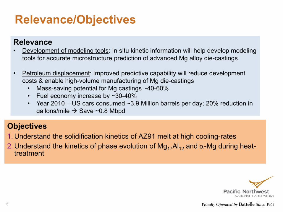
Relevance/Objectives
Objectives1. Understand the solidification kinetics of AZ91 melt at high cooling-rates2. Understand the kinetics of phase evolution of Mg17Al12 and α-Mg during heat-
treatment
3
Relevance• Development of modeling tools: In situ kinetic information will help develop modeling
tools for accurate microstructure prediction of advanced Mg alloy die-castings
• Petroleum displacement: Improved predictive capability will reduce development costs & enable high-volume manufacturing of Mg die-castings • Mass-saving potential for Mg castings ~40-60%• Fuel economy increase by ~30-40%• Year 2010 – US cars consumed ~3.9 Million barrels per day; 20% reduction in
gallons/mile Save ~0.8 Mbpd
4
Technical Barriers
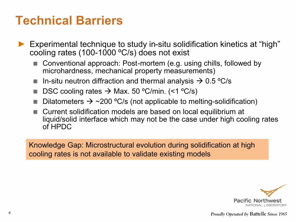
Experimental technique to study in-situ solidification kinetics at “high” cooling rates (100-1000 ºC/s) does not exist
Conventional approach: Post-mortem (e.g. using chills, followed by microhardness, mechanical property measurements)In-situ neutron diffraction and thermal analysis 0.5 ºC/sDSC cooling rates Max. 50 ºC/min. (<1 ºC/s)Dilatometers ~200 ºC/s (not applicable to melting-solidification)Current solidification models are based on local equilibrium at liquid/solid interface which may not be the case under high cooling rates of HPDC
Knowledge Gap: Microstructural evolution during solidification at high cooling rates is not available to validate existing models
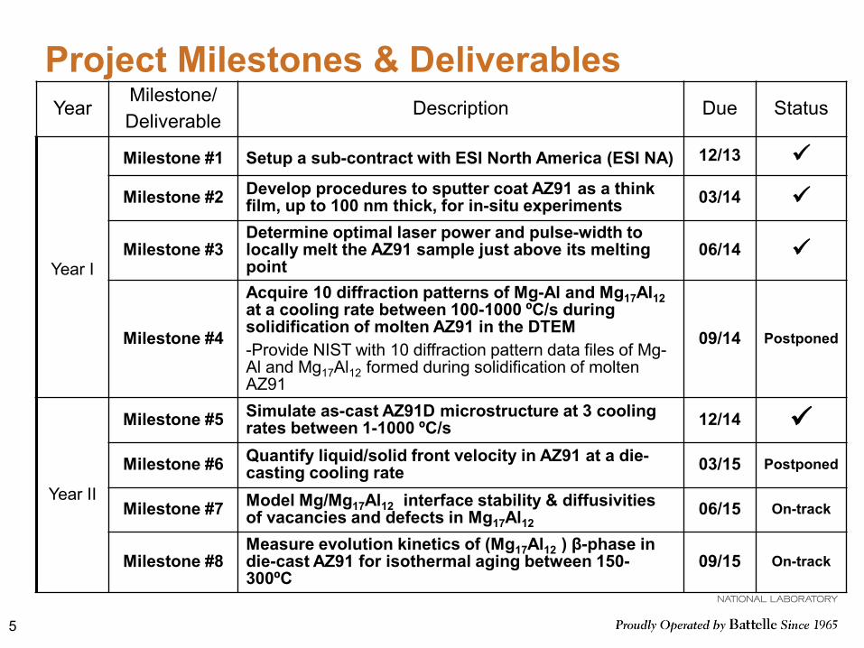
Project Milestones & DeliverablesYear
Milestone/Deliverable
Description Due Status
Year I
Milestone #1 Setup a sub-contract with ESI North America (ESI NA) 12/13
Milestone #2 Develop procedures to sputter coat AZ91 as a think film, up to 100 nm thick, for in-situ experiments 03/14
Milestone #3Determine optimal laser power and pulse-width to locally melt the AZ91 sample just above its melting point
06/14
Milestone #4
Acquire 10 diffraction patterns of Mg-Al and Mg17Al12at a cooling rate between 100-1000 ºC/s during solidification of molten AZ91 in the DTEM-Provide NIST with 10 diffraction pattern data files of Mg-Al and Mg17Al12 formed during solidification of molten AZ91
09/14 Postponed
Year II
Milestone #5 Simulate as-cast AZ91D microstructure at 3 cooling rates between 1-1000 ºC/s 12/14
Milestone #6 Quantify liquid/solid front velocity in AZ91 at a die-casting cooling rate 03/15 Postponed
Milestone #7 Model Mg/Mg17Al12 interface stability & diffusivities of vacancies and defects in Mg17Al12
06/15 On-track
Milestone #8Measure evolution kinetics of (Mg17Al12 ) β-phase in die-cast AZ91 for isothermal aging between 150-300ºC
09/15 On-track
5

Technical Approach
Develop in-situ melting/solidification technique
inside an electron microscope for imaging the solidification of Mg
alloys
Correlate experimental data with predictions from commercial
solidification software (ProCAST) and to determine validity of the
code for HPDC Mg alloys
Develop in-situ heat-treatment approach to study kinetics of
phase evolution in as-cast microstructure
Perform atomistic simulations to understand microstructural evolution in non-equilibrium
microstructure
AZ91(Applicable to other Mg alloys as well)
Experimental Modeling
6

Project Tasks
Task 1: Project Management
• DTEM sample fabrication• DTEM in-situ solidification characterization
Task 2: Determination of in-situ solidification kinetics
• Specimen fabrication for STEM• In-situ heat-treatment & characterization
Task 3: Determination of in-situ kinetics during heat-treatment
• Back-diffusion thermodynamics calculations• Microstructure prediction calculations
Task 4: Solidification Modeling
• Structural property calculation of α-Mg and Mg17Al12 phases• Effect of defects and vacancies
Task 5: First-principles Atomistic Modeling
7

Background:In-situ Solidification Kinetics Concept
Nucleation/growth kineticsPhase volume fractionsVelocity of solid/liquid interface
AZ91 Sample (~100 nm)(Sputter Coated or
FIB Milled from Bulk)
Melt PoolTemp. = T1
Time, t Time, t+∆t∆t = ns10s
SolidificationRegions
Time delayed (∆t)electron beam
Melt PoolTemp. < T1
Image orDiffraction PatternOn CCD Camera
8
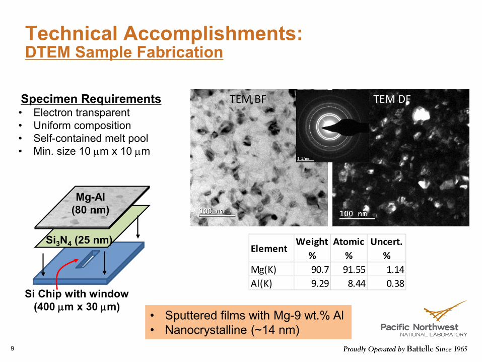
Technical Accomplishments:DTEM Sample Fabrication
TEM BF TEM DF
ElementWeight
%Atomic
%Uncert.
%Mg(K) 90.7 91.55 1.14Al(K) 9.29 8.44 0.38
• Sputtered films with Mg-9 wt.% Al• Nanocrystalline (~14 nm)
Specimen Requirements• Electron transparent• Uniform composition• Self-contained melt pool• Min. size 10 µm x 10 µm
Si Chip with window(400 µm x 30 µm)
Si3N4 (25 nm)
Mg-Al(80 nm)
9

Copyright © ESI Group, 2009. All rights reserved.Copyright © ESI Group, 2009. All rights reserved.
Technical Accomplishments:Thermal Modeling (in-situ melting)
• Predicted cooling rate >> 1000 K/s• Pre-heat TEM specimen during In-situ melting
Si Wafer (T0= 25C)
Mg-Al Film (T0= 25C)
Melt Pool (T0= 610C)

Technical Accomplishments:Ex-situ Laser Melting Results
Si-window edge
Large elongated grains after solidification
• Melting: 532 nm Nd:YAG pulsed laser, 0.35 mJ, 1µs pulse-length
• Work on DTEM on-going• Incorporated Zn in the sputtered film
AZ91 filmElectron-transparentsputtered Mg-Al film
Electron-opaqueSi chip
11
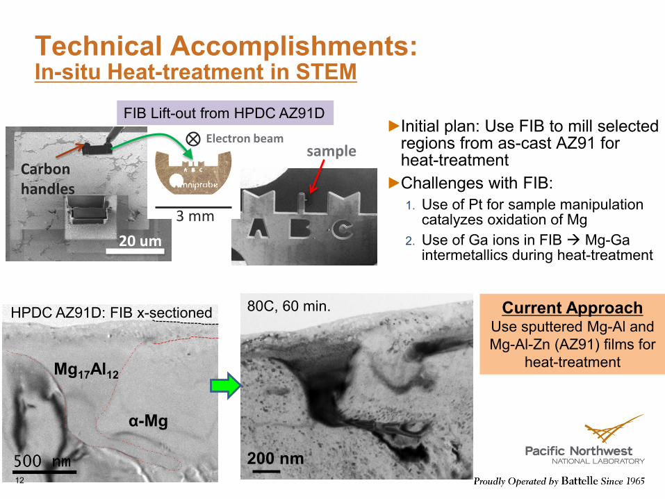
Technical Accomplishments:In-situ Heat-treatment in STEM
Initial plan: Use FIB to mill selected regions from as-cast AZ91 for heat-treatmentChallenges with FIB:1. Use of Pt for sample manipulation
catalyzes oxidation of Mg2. Use of Ga ions in FIB Mg-Ga
intermetallics during heat-treatment20 um
Carbon handles
3 mm
sampleElectron beam
FIB Lift-out from HPDC AZ91D
200 nm
80C, 60 min. Current ApproachUse sputtered Mg-Al and Mg-Al-Zn (AZ91) films for
heat-treatment
α-Mg
Mg17Al12
HPDC AZ91D: FIB x-sectioned
12

Technical Accomplishments:Microstructure Evolution (STEM)
As-sputtered 200 C, 15 min 200 C, 30 min200 C, 5 min
Grain size evolution in Mg-9 wt.% Al films (TEM Bright Field)
Dn - Don = Kt
K = Ko exp (-Q/RT)
D: Size of α or Mg17Al12Do: Initial sizen: Growth exponentK: Growth constantt: TimeT: Temperature
Resultsn: Growth exponent vs. temperatureQ: Activation energy for growth
13
Copyright © ESI Group, 2009. All rights reserved.Copyright © ESI Group, 2009. All rights reserved.
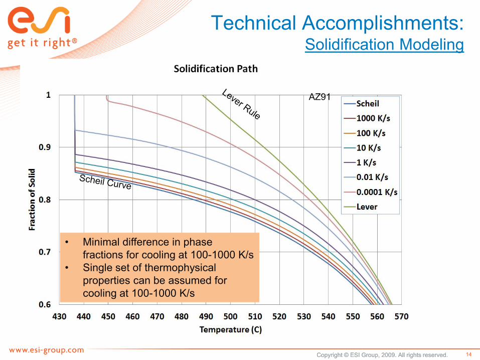
Technical Accomplishments: Solidification Modeling
• Minimal difference in phase fractions for cooling at 100-1000 K/s
• Single set of thermophysicalproperties can be assumed for cooling at 100-1000 K/s
AZ91
14
Copyright © ESI Group, 2009. All rights reserved.Copyright © ESI Group, 2009. All rights reserved.
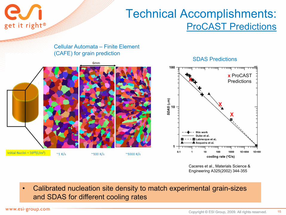
Technical Accomplishments:ProCAST Predictions
• Calibrated nucleation site density to match experimental grain-sizes and SDAS for different cooling rates
x ProCASTPredictions
Cellular Automata – Finite Element (CAFE) for grain prediction
SDAS Predictions
Caceres et al., Materials Science & Engineering A325(2002) 344-355
15

Technical Accomplishments:Atomistic Modeling
Tested two modified Embedded Atom Method (MEAM) potentials
Potential 1: Al/Si/Mg/Cu/Fe (Binary) MEAM Potential (available from NIST)B. Jelinek, S. Groh, M. F. Horstemeyer, J. Houze, S. G. Kim, G. J. Wagner, A. Moitra and M. I. Baskes, Phys Rev B 85, 245102 (2012)
Potential 2: Al-Mg PotentialY.-M. Kim N. J. Kim, B.-J. Lee, CALPHAD: Computer Coupling of Phase Diagrams and Thermochemistry 33 (2009) 650–657
-Potential 1 gave properties (for Mg17Al12) that didn’t match literature data
• negative elastic constants c44, c55, c66
• +ve heat of formation
• -ve formation energy (substitutional atom)
-We modified various parameters of Potential 2 to get physical properties of Mg, Al, Mg-Al and Mg17Al12 close to DFT/experimental values
16

Technical Accomplishments:Atomistic Modeling (Mg17Al12 Properties)
Good correlation with DFT and reported experimental values
[2] POSTEC CMSE LAB. https://cmse.postech.ac.kr/lammps/3707. Accessed June 10, 2014.
[3] Jelinek, B.; et al “Modified Embedded Atom Method Potential for Al, Si, Mg, Cu, and Fe Alloys.” Phys Rev B (85), 2012; pp. 245102.
[6] Kim, Y.-M.; et al. “Atomistic Modeling of Pure Mg and Mg–Al Systems. ” CALPHAD: Computer Coupling of Phase Diagrams and Thermochemistry (33), 2009; pp. 650–657.
17
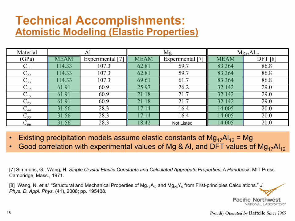
Technical Accomplishments:Atomistic Modeling (Elastic Properties)
[7] Simmons, G.; Wang, H. Single Crystal Elastic Constants and Calculated Aggregate Properties. A Handbook. MIT Press Cambridge, Mass., 1971.
[8] Wang, N. et al. “Structural and Mechanical Properties of Mg17Al2 and Mg24Y5 from First-principles Calculations.” J. Phys. D. Appl. Phys. (41), 2008; pp. 195408.
• Existing precipitation models assume elastic constants of Mg17Al12 = Mg• Good correlation with experimental values of Mg & Al, and DFT values of Mg17Al12
Not Listed
18

Response to Reviewers’ Comments
1st year for review
19

Collaboration
ESI North America (sub-contract)Solidification modelingThermal modeling of in-situ melting and solidification
20

Remaining Challenges & Barriers
ChallengeDTEM up and running
Optimize imaging conditions (signal-to-noise)Reduce the in-situ cooling rate (100-1000 ºC/s)
BarrierInability to measure temperature inside the DTEM
21

Proposed Future Work:Upcoming Project Work
Perform DTEM experimentsSolidification modeling
Use in-situ DTEM data for modelingHeat-treatment
Determine grain growth kinetics and study effects of Zn (binary vs. ternary films)
Atomistic modelingDetermine diffusion coefficients and effective migration barriers as a function of Al concentration and temperature
22

Summary
The goal is to understand the kinetics & diffusion in Mg alloys under non-equilibrium conditions AZ91 as a model systemEx-situ laser melting/solidification experiments and their thermal modeling has been completed Work on in-situ melting/solidification in a dynamic TEM is in progressFIB-based technique for specimen extraction from bulk AZ91 alloy poses unique challenges for in-situ heat-treatment in TEM Sputtered films are being used to study microstructural evolution during heat-treatmentProCAST calibration parameters for SDAS and grain-size in AZ91 have been determined. Goal is to compare in-situ solidification results with ProCASTpredictionsAtomistic modeling has improved upon existing Mg-Al potential to predict Mg17Al12 properties Kinetic Monte Carlo method is being used to simulate microstructural evolution of heat-treated sputtered films
23

Technical Back-Up Slides
24
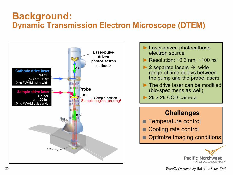
Background:Dynamic Transmission Electron Microscope (DTEM)
Laser-driven photocathode electron sourceResolution: ~0.3 nm, ~100 ns2 separate lasers wide range of time delays between the pump and the probe lasersThe drive laser can be modified (bio-specimens as well)2k x 2k CCD camera
ChallengesTemperature controlCooling rate controlOptimize imaging conditions
25

Technical Accomplishments:Ex-situ Laser Melting Calibration
5 mJ2.5 mJ
1 mJ0.5 mJ
500 µm
10 µm
0.2 mJ
SEM
SEMLaser-Melting Parameters
0.35 mJ energy1µs pulse-length
• Pulsed Nd:YAGlaser (532 nm)
• Pulse length: 1 µs• Single-shot mode• Melt in ambient
26

Technical Issues:In-situ Heat-treatment in STEM
Initial planUse FIB to mill selected regions from as-cast AZ91 for heat-treatment
Challenges with FIB1. Use of Pt for sample manipulation
catalyzes oxidation of Mg2. Use of Ga ions in FIB Mg-Ga
intermetallics during heat-treatmentMg-Ga Intermetallics
27
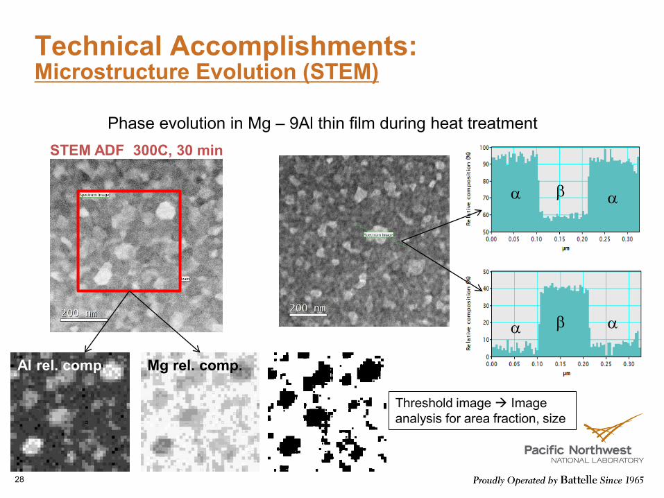
Technical Accomplishments:Microstructure Evolution (STEM)
Phase evolution in Mg – 9Al thin film during heat treatment
Threshold image Image analysis for area fraction, size
Al rel. comp. Mg rel. comp.
STEM ADF 300C, 30 min
α αβ
α αβ
28
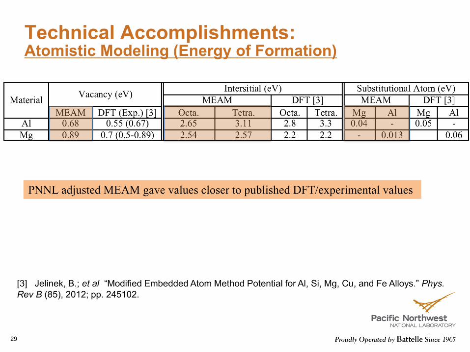
Technical Accomplishments:Atomistic Modeling (Energy of Formation)
PNNL adjusted MEAM gave values closer to published DFT/experimental values
[3] Jelinek, B.; et al “Modified Embedded Atom Method Potential for Al, Si, Mg, Cu, and Fe Alloys.” Phys. Rev B (85), 2012; pp. 245102.
29