Mean square deviation Root mean square deviation Variance Standard deviation.

-
MarForm. Form Measur ing Ins t ruments
IN OUR VIEW, FORM DEVIATION IS NOT A QUESTION
OF PERCEPTION. THAT IS WHY WE HAVE MARFORM
To ensure problem-free functioning and durability of a workpiece, the key factors are its dimensions and, above all , its form.
Requirements in terms of roundness, flatness, straightness, coaxiality or run-out - particularly when it comes to axis-symmetri-
cal workpieces - are becoming increasingly strict . These requirements can only be reliably tested and met using high-precision
formtesters optimized for this purpose. Whether you are dealing with fuel injection technology, microelectronics, precision
mechanics or medical technology, the key functional components are becoming ever smaller and ever more precise. To enable
the production department to take advantage of the specified tolerances, measuring uncertainty must be kept as low as possi-
ble. MarForm helps you to reduce process costs without increasing testing costs thanks to stable, innovative instruments with
the highest possible level of automation, flexibility and precision. MarForm offers the ideal combination for all requirements.

+
MarForm. Form Measur ing Ins t ruments
Formtester Reference Machine
MarForm MFU 100 17-11MarForm MFU 800 17-12MarForm MFK 600 17-13
MarForm. Form Measuring Instruments
Formtester
MarForm MMQ 10 17- 3MarForm MMQ 100, MMQ 6100 extended 17- 4MarForm MMQ 34 17- 5EasyForm. Sof tware 17- 5MarForm MMQ 44 17- 6FORM-PC. Sof tware 17- 7
MarWin. Sof tware 17-14
Accessor ies 17-20
Universa l Measur ing Machine
Pr imar 17-22
MarForm. Overv iew 17-16

-
MarForm. Form Measur ing Ins t ruments17-2
The demands placed on a form measuring instrument are as varied as those for workpieces and measuring tasks. There are
several things that have to be taken into consideration when selecting the right instrument: Which measuring axes are required
and in what length and precision? Are there particular requirements in terms of positioning accuracy, e.g. for particularly small
workpieces, or in terms of the workpiece mount and probe arm geometry? Does the measuring instrument need to minimize
the influence of the operator through a high level of automation? Ultimately, the key criterion is that all measurements can be
performed and documented simply, cost-effectively and reproducibly. The ideal MMQ is available for every task!
MarForm. Formtesters for a Wide Range of ApplicationsFORM MEASURING INSTRUMENTS FOR THE WORKBENCH OR INSPECTION ROOM

+
MarForm. Form Measur ing Ins t ruments 17-3
MarForm MMQ 10
Description
In order to be able to identify production errors immediately andeliminate them as quickly as possible, metrology is more importantthan ever for testing form and positional deviations. It helps you tominimize time-consuming and costly reworking and rejection rates.The compact, user-friendly and versatile MarForm MMQ 10Formtester is truly an essential piece of kit for anyone involved intesting form and positional deviations.Its robust and functional design makes the MarForm MMQ 10not only suitable for use in the laboratory, but also for the rigors ofthe workshop.
Features
Versions
MMQ 10 with integrated form computer to evaluate form and positional tolerances (DIN ISO 1101) for roundness, radial run-out, concentricity and coaxiality.MMQ 10 with FORM-PC as a powerful, PC-based evaluationsystem running on Windows® 2000 offers informative color records with easy-to-use software for evaluation of form and positional tolerances (DIN ISO 1101) for roundness, roundness sector, radial run-out, axial run-out, concentricity, coaxiality, flatness(1),straightness(1), parallelism(1) and perpendicularity(1).In the USA, the MMQ 6100 with touchscreen operation is also available.(1) = from a polar trace
Options (for MMQ and FORM-PC)
Fourier analysis to expand the evaluation capabilities for the rollerbearing sector. Mahr Data Transfer Tools for simple transfer of measurement results into statistical evaluations such as QS-STATor MS Excel.
(1) (1) (1) (1)
The compact roundness measuring station for production and laboratory
• Precise and fast measurement results• Compact, mobile, reliable• Suitable for use in workshop• Large measuring volume• Mobile due to its low weight and convenient size• Fast workpiece alignment thanks to computer support• Centering and tilting screws for rough and fine adjustment• Universal and reliable• Suitable for use in workshop since no compressed air connection
is required• Can optionally be supplied with integrated evaluation computer
or powerful FORM-PC.
-
MarForm. Form Measur ing Ins t ruments17-4
MarForm MMQ 6100 extended
Features
• Medium to large parts
• Equally at home on the shop-floor or lab
• Compact, bench-top design
• Touch screen control
• Mahr Federal Windows®-based software
MarForm™ MMQ 6100 extended Circular Form Systemincludes...
• Precision, 220 mm/8.6 in mechanical bearing spindle• Integral tilt and centering table• Shock-absorbing heavy duty base for stability• Lever type gage head• Windows Operating System and Mahr Federal’s proven
Metrology Software Package• Color monitor with touch screen control• 100 mm/4 in built-in thermal printer• Available as 120 or 220 Volts 50/60 Hz
Also available with a motorized gage headstand (X and Z):MarForm MMQ 6200
Extended Circular Form System
(1) (1) (1) (1)
Features
The MMQ 100 offers superior accuracy in a rugged, shop floor hardened package. In combination with the EasyForm Software itrepresents the perfect solution for simple yet powerful measuringtasks.MMQ 10 + MMQ 6100 + EasyForm = MMQ 100The MMQ 100 combines the advantages of the MMQ 10 and the MMQ 6100 with the power of EasyForm:
• Precise and fast measurement results• Compact, mobile, reliable• Suitable for use in workshop• Large measuring volume• Mobile due to its low weight and convenient size• Fast workpiece alignment thanks to computer support• Centering and tilting screws for rough and fine adjustment• Universal and reliable• Suitable for use in workshop since no compressed air connection
is required• No keyboard or mouse required• Encoders in X and Z feed position directly to the sw (optional)
Satisfies most form analysis situations• Roundness (also in a sector)• Flatness(1) (out of one circle)• Concentricity• Coaxiality• Radial run-out• Axial run-out• Circular parallelism of top and bottom faces• Harmonic Analysis
(1) = from a polar trace
The MMQ 100 can be operated with EasyForm or Form-PC
MarForm MMQ 100
(1) (1) (1) (1)

+
MarForm. Form measur ing ins t ruments 17-5
Touch Screen Software EasyForm
If you are using your Form measuring instrument close to theproduction line you may not want to fiddle around with a keyboardor a mouse. Our Touch-Screen user interface turns taking measu-rements into child's play. All necessary functions are literally at yourfinger tips.Your operator - and subsequently your operating cost - will benefitfrom the fact that the number of steps (or touches) it takes to get a result are kept to a minimum.You can perform a roundness measurement in as little as two sim-ple steps. And the software will guide you through any optionaladjustment you would like to make.The EasyForm Software remembers every step of your measure-ment. It doesn't matter if you need to repeat the most recent mea-surement or if you decide to combine several measurements andevaluations on one part to a comprehensive program: The EasyForm Teach-In feature will learn what you want!
You can store any measurement task with one of the pro-grammable function keys
EasyForm is based on highly optimized MarWin measurementand evaluation routines and can also be combined with otherMarWin modules. It runs on Windows® operating systems andincludes functions for user administration, network support, electronic storage of results and is extendable for future options.
The easy way to operate a Formtester
Features
• Intuitive user interface for immediate measurements• Interactive, automatic program generation• 3D representation of cylindricity, flatness and total run-out - color
or also with auxiliary lines and interactive, internal graphic preview• Immediate measuring results (values and graphics) on screen• Concise measuring records as a screen preview, on file (also
network) or paper (on all Windows printers)• Operating system: Windows®2000 or Windows® XP
Features
The MMQ 34 is equipped with a high accuracy motorized Z-column and therefore opens a whole other dimension compared to basic roundness gages.
In addition to• Roundness (also in a sector)• Flatness(1) (out of one circle)• Concentricity• Coaxiality• Radial run-out• Axial run-out
It allows you to determine:• Cylindricity• Straightness (using Z and/or C)• Total Radial Run-Out• Parallelism (using Z and/or C)• Perpendicularity (using Z and/or C)• Angularity (vertical)• Taper • Cone Form
It offers an unusual large measuring and load capacity withoutoccupying much space.
(1) = from a polar trace
The MMQ 34 can be operated with EasyForm or Form-PC
MarForm MMQ 34
(1)

-
MarForm. Form Measur ing Ins t ruments17-6
MarForm MMQ 44
MMQ 44 can be used in all circumstances for comprehensiveworkpiece evaluation to DIN ISO 1101. High-precision Z and X measuring axes make it possible to perform any form measuringtask.
There are versions of MarForm MMQ 44 for• High-precision workpieces• Unusually long workpieces• Large and heavy workpieces• Use in production environments or the precision inspection room
You can select between a variety of modules which can be used tocustomize the MarForm MMQ 44 to your precise requirements:• Motor-driven or manual centering and tilting table• Vertical axis (Z) with measuring length of 500 mm/19.7 ” or
350 mm/13.8 “
• Horizontal axis (X) with length of 180 mm/ 7.1 “ or 280 mm/11.0 “• Horizontal axis as positioning axis (manual or motor-driven) or as
measuring axis• With digital rotary encoders or linear scales in X and Z axes
This means that your MarForm MMQ 44 is available as a "semi-automatic measuring station" with a manual centering and tiltingtable or as a "fully automatic measuring station" which is conveniently fitted with a motor-driven centering and tilting tableand the T7W probe and makes it possible to test parts with high precision without operator intervention.The Marform MMQ 44 Formtester can be used in all applicationsfor comprehensive workpiece evaluation to DIN ISO 1101. OptionalFourier analysis and synthesis expand the evaluation possibilities tosatisfy the demands of the roller bearing sector.
The Piston option takes into account measuring tasks performedby piston manufacturers.
The Mahr Data Transfer Tools make it easy to transfer measurement results into statistical evaluations such as QS-STATor MS Excel.
In the USA, this unit is also available as a roundness measuringinstrument with a manual tilting and centering table. MMQ 6100extended with a manually adjustable measuring stand (X-/Z-axes)or MMQ 6200 with motor-driven positioning axes.
Features
Description
The modular design equipped with all the required componentsenables you to configure the optimum solution for a wide range of tasks. The fact that all of the available modules were developedand manufactured in Germany with hallmark Mahr quality guarantees the legendary precision and stability of the MarFormmeasuring instruments. This ensures the reliability of each and everymeasurement for years to come.
Due to its workshop-compatible design, the MarForm MMQ 44Formtester can be used both in production and in the precisioninspection room. The high-precision rotary stroke bearings and sliding bearings used as guide elements combine low outlay interms of installation, maintenance and operating costs with reliable measurement results even when used in production environments.
Modular and flexible - this instrument can be used in all applications for comprehensive workpiece evaluation to DIN ISO 1101
+
MarForm. Form Measur ing Ins t ruments 17-7
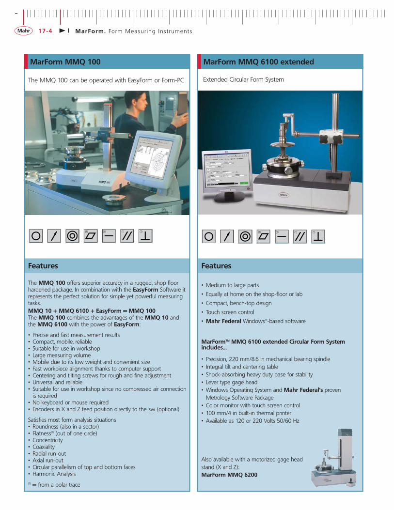
MarForm. FORM-PC Evaluation Software
The FORM-PC gives you total control of your form measuring station. It responds to a click of the mouse. The graphical user interface gives you a constant overview whether you are performing positioning, alignment, measurement or documentationtasks.
This means that that you can not only measure the quality of yourproducts in compliance with standards, but also depict it in a clearand illustrative manner. Naturally, the measuring records can be stored electronically, documented in paperless form and sent electronically, e.g. by e-mail. The versatile Windows® PC peripheralunit with its high-resolution printers also enables perfect documentation of your measurement results in color or black andwhite.
The measurement, control and evaluation system for MMQ
Description
Features
• The familiar Windows® user interface means that users get to grips with the new system very quickly
• Clear windows structure• Ease of operation using mouse• Many of the functions can be selected directly via informative
icons • Profile display during measurement, i.e. direct visual evaluation of
profile during the measurement process• Evaluation compliant with DIN ISO 1101• For individual and series measurements• Rapid results with Quick&Easy• Teach-in programming for measurement and evaluation
processes (no programming knowledge required)• User-friendly measuring program administration
-
MarForm. Form Measur ing Ins t ruments17-8
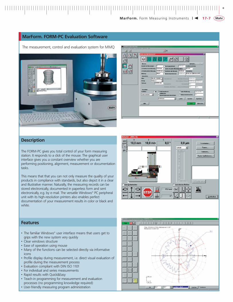
MarForm. FORM-PC Evaluation Software
• Measuring program process with high level of automation• 3D representation of cylindricity, flatness and total run-out -
color or also with auxiliary lines and interactive, internal graphic preview
• Concise measuring records as a screen preview, black and white or color - on all Windows® printers
• Configuration of measuring station via menus• Operating system and user interface: Windows® 2000 SP4
The following form features can be evaluated:• Roundness• Cylindricity• Straightness• Flatness• Concentricity• Coaxiality• Radial run-out, total radial run-out• Axial run-out, total axial run-out• Parallelism, perpendicularity and angularity to DIN ISO 1101• In addition: Conicity and roundness evaluation in the angular
sector and taper
Additional functions complement the scope of supply.The Piston measurement option for FORM-PC makes it possible tocarry out a wide range of measurement and evaluation tasks onengine pistons simply and efficiently.
Export of measurement results from the measurement recordsin a Windows® format for further processing, e.g. using statisticalsoftware packages or applications such as Excel.
Evaluation of waviness using a Fast Fourier Transformation(FFT). The Fourier analysis enables you to assess the quality of afinished workpiece.
+
MarForm. Form Measur ing Ins t ruments 17-9
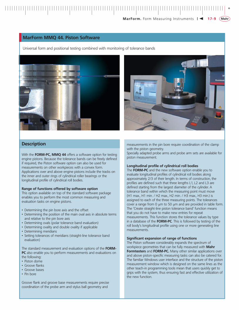
MarForm MMQ 44. Piston Software
Universal form and positional testing combined with monitoring of tolerance bands
With the FORM-PC, MMQ 44 offers a software option for testingengine pistons. Because the tolerance bands can be freely definedif required, the Piston software option can also be used for measurements on other workpieces with a convex form.Applications over and above engine pistons include the tracks onthe inner and outer rings of cylindrical roller bearings or the longitudinal profile of cylindrical roll bodies.
Range of functions offered by software optionThis option available on top of the standard software package enables you to perform the most common measuring and evaluation tasks on engine pistons.
• Determining the pin bore axis and the offset• Determining the position of the main oval axis in absolute terms
and relative to the pin bore axis• Determining ovals (polar tolerance band evaluation)• Determining ovality and double ovality if applicable• Determining meridians• Setting tolerances of meridians (straight-line tolerance band
evaluation)
The standard measurement and evaluation options of the FORM-PC also enable you to perform measurements and evaluations onthe following:• Piston dome• Groove flanks• Groove bases• Pin bore
Groove flank and groove base measurements require precise coordination of the probe arm and stylus ball geometry and
measurements in the pin bore require coordination of the clampwith the piston geometry.Specially adapted probe arms and probe arm sets are available forpiston measurement.
Longitudinal profile of cylindrical roll bodiesThe FORM-PC and the new software option enable you to evaluate longitudinal profiles of cylindrical roll bodies along approximately 2/3 of their length. In terms of construction, the profiles are defined such that three lengths L1, L2 and L3 are defined starting from the largest diameter of the cylinder. A tolerance band within which the measuring point must move (H1 max., H1 min. / H2 max., H2 min. / H3 max., H3 min.) is assigned to each of the three measuring points. The tolerancescover a range from 0 µm to 50 µm and are provided in table form.The 'Create straight-line piston tolerance band' function means that you do not have to make new entries for repeat measurements. This function stores the tolerance values by type in a database of the FORM-PC. This is followed by testing of theroll body's longitudinal profile using one or more generating linemeasurements.
Significant expansion of range of functionsThe Piston software considerably expands the spectrum of workpiece geometries that can be fully measured with MahrFormtesters and FORM-PC. Many other similar applications overand above piston-specific measuring tasks can also be catered for.The familiar Windows user interface and the structure of the pistonmeasurement window which is designed on the same lines as theother teach-in programming tools mean that users quickly get togrips with the system, thus ensuring fast and effective utilization ofthe new function.
Description
-
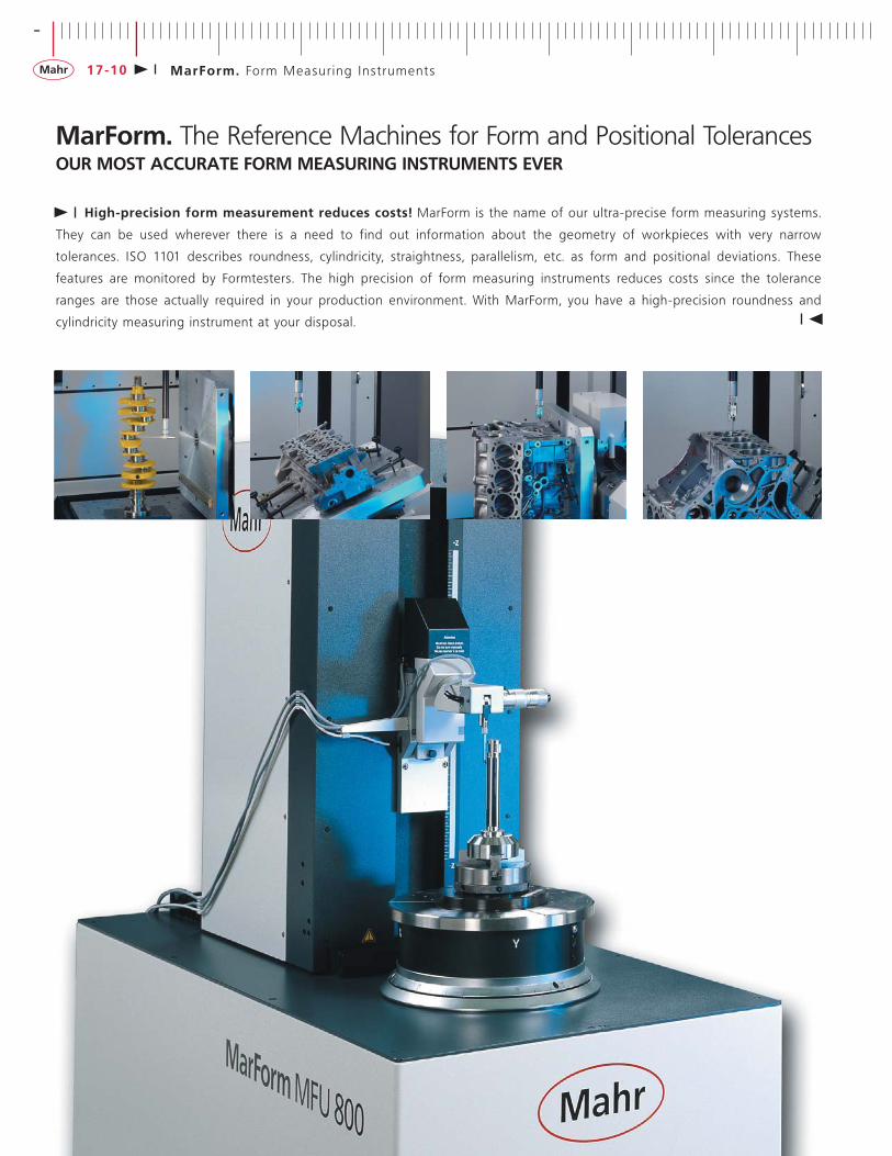
MarForm. Form Measur ing Ins t ruments17-10
MarForm. The Reference Machines for Form and Positional TolerancesOUR MOST ACCURATE FORM MEASURING INSTRUMENTS EVER
High-precision form measurement reduces costs! MarForm is the name of our ultra-precise form measuring systems.
They can be used wherever there is a need to find out information about the geometry of workpieces with very narrow
tolerances. ISO 1101 describes roundness, cylindricity, straightness, parallelism, etc. as form and positional deviations. These
features are monitored by Formtesters. The high precision of form measuring instruments reduces costs since the tolerance
ranges are those actually required in your production environment. With MarForm, you have a high-precision roundness and
cylindricity measuring instrument at your disposal .

+
MarForm. Form Measur ing Ins t ruments 17-11
MarForm MFU 100
Description
The MarForm MFU 100 has a full range of functions:
• Roundness measuring instrument circular (C)• Motor-driven centering and leveling table (X, Y, A, B)• Straightness measuring axis vertical (Z)• Straightness measuring axis horizontal (X)• Tangential multi-function axis (Y)• Motor-driven length measuring probe T7W• MarWin evaluation software for form and positional features
All the axes are coordinated to ensure maximum measuring certainty.The horizontal X-axis is located above the center of the workpiece,therefore making it possible to test the "true parallelism" free fromother measuring influences.The tangential Y-axis is a new and innovative feature. This additional new axis for conventional formtesters helps to locate the zenith of very small workpiece geometries in motor-driven applications and does so free from user influence. Thismeans that the actual precision measurement can be started atexactly the right location, thus significantly increasing the processaccuracy.
The Y-axis is also the instrument that enables you to determine theworkpiece diameter in combination with the vertical Z-axis and thehorizontal X-axis. As a result, tolerances in the sub-µm range can
for the first time be tested standard-compliant using the maximum-material principle, while stile offering a unique price/performanceratio.
When used in combination with the machine electronics, high-resolution digital scales ensure a level of positioning quality whichmakes it possible to test even the smallest component geometries.The MarForm MFU 100 is also ideally suited to scanning surfaces.
The MarWin software package offers the complete range of functions you would expect from a modern measuring and evaluation software package, including attractive records and electronic documentation in your corporate network.
Due to the deliberate separation of control and evaluation, theMarForm MFU 100 is future-proof and expandable. Newlanguage versions, special evaluations and new standards can all be incorporated with ease. The MFU 100 is also designed to beable to use sensors developed in the future.
In short, the MarForm MFU 100 represents a new generation ofreference form measuring instrument for precision inspection rooms and production environments.
Taking the reference form measuring center to a new level
The road from high-precision measurement axes to reliable measurements is often a long one - and no instrument is better suited for this purpose than the MFU 100. Only the MFU 100 has integrated reference elements for real-time spatial compensation ofgeometrical deviations and therefore records all profiles as high-precision 3D coordinates.
For decades, MarForm measuring instruments have been renownedfor their precision and stability. The new MarForm MFU 100 wasdeveloped with the objective of testing the form and positional features of parts with measuring volumes of a liter cost-effectively ina production environment. Our many years of experience have takenthe new MFU 100 to a new level.
With the MarForm MFU 100, you have a high-precision measuringinstrument at your disposal whose extremely low measuring uncertainty increases the tolerance range in production environmentsand thus reduces production costs.
-
MarForm. Form Measur ing Ins t ruments17-12
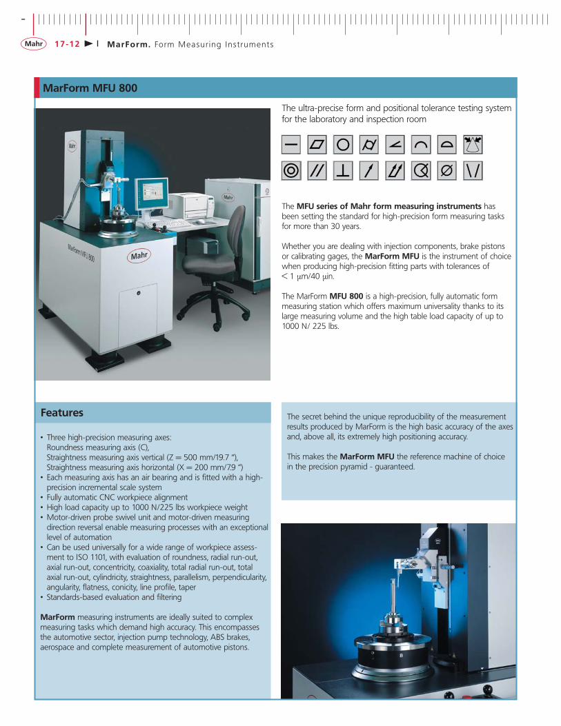
MarForm MFU 800
Features
• Three high-precision measuring axes:Roundness measuring axis (C),Straightness measuring axis vertical (Z = 500 mm/19.7 “),Straightness measuring axis horizontal (X = 200 mm/7.9 “)
• Each measuring axis has an air bearing and is fitted with a high-precision incremental scale system
• Fully automatic CNC workpiece alignment• High load capacity up to 1000 N/225 lbs workpiece weight• Motor-driven probe swivel unit and motor-driven measuring
direction reversal enable measuring processes with an exceptionallevel of automation
• Can be used universally for a wide range of workpiece assess-ment to ISO 1101, with evaluation of roundness, radial run-out, axial run-out, concentricity, coaxiality, total radial run-out, total axial run-out, cylindricity, straightness, parallelism, perpendicularity, angularity, flatness, conicity, line profile, taper
• Standards-based evaluation and filtering
MarForm measuring instruments are ideally suited to complexmeasuring tasks which demand high accuracy. This encompassesthe automotive sector, injection pump technology, ABS brakes,aerospace and complete measurement of automotive pistons.
The secret behind the unique reproducibility of the measurementresults produced by MarForm is the high basic accuracy of the axesand, above all, its extremely high positioning accuracy.
This makes the MarForm MFU the reference machine of choice in the precision pyramid - guaranteed.
The ultra-precise form and positional tolerance testing systemfor the laboratory and inspection room
The MFU series of Mahr form measuring instruments has been setting the standard for high-precision form measuring tasks for more than 30 years.
Whether you are dealing with injection components, brake pistons or calibrating gages, the MarForm MFU is the instrument of choicewhen producing high-precision fitting parts with tolerances of < 1 µm/40 µin.
The MarForm MFU 800 is a high-precision, fully automatic formmeasuring station which offers maximum universality thanks to itslarge measuring volume and the high table load capacity of up to1000 N/ 225 lbs.

+
MarForm. Form Measur ing Ins t ruments 17-13
MarForm MFK 600
Features
Generous, optimized construction ensures high measuring accuracyover the entire machine volume, 7 motor-driven axes, 5 of whichare measuring axes.
• Universal form measuring station with large measuring volume for heavy workpieces
• 5 measuring axes and 2 calibration axes for measuring form elements and determining positions
• Easy to use and can be set up quickly using rotating probe and automatically positioned workpiece
• Low maintenance and able to deal with continuous loads thanks to air bearings
• Collision-protected tracing systems for a wide range of measuring tasks
• Large workpiece mounting area for large individual workpieces or clamps holding several workpieces
• Roundness measuring unit with automatic adjustment to the diameter of the workpiece even if position is eccentric
• Straightness measurements in 3 main coordinate directions• Workpiece evaluation to ISO 1101
The MFK 600 Formtester is particularly suited to testing engineblocks, cylinder heads, gearboxes, hydraulic components, crank-shafts and camshafts. Large measuring and travel paths enable easy and safe changing of workpieces. Testing is performed using machine and workpiece coordinates, making it suitable for
production environments.The MFK 600 takes care of all evaluation tasks for form and positional features, diameters and positional values.
A wide range of accessories and probes offer an optimum solutionfor all measuring tasks.
The MFK 600 can optionally be expanded with additional axes ofmovement. These are used to rotate workpieces while the program is running. This means that complex measuring tasks such as those required for V engine blocks can be performedwithout user intervention.
The reference form measuring center for the laboratory andinspection room
Measuring Accuracypath
C-axis 360° 0.1 µm (3.9 µin)Z-axis 1000 mm (39.4 “) 0.5 µm/100 mm (19.7 µin/3.9 “)X-axis 120 mm (4.7 “) 2 µm (80 µin)Tx-axis 1100 mm (43.3 “) 1 µm/100 mm (40µin/3.9 “)Ty-axis 550 mm (21.6 “) 1 µm/100 mm (40µin/3.9 “)
Workpiece weight: Up to 800 kg (1763 lbs)
Further information is available on request
Overview of technical data
With its coordinated components, the MFK 600 form measuringstation offers impressive flexibility and can be adapted for a widerange of metrology applications.
The base of this Formtester is made of distortion-free, oscillation-isolated granite. Its high-precision horizontal surface forms the reference plane for the test setup, while the workpiece mountingtable carries and guides heavy workpieces over the granite surfaceusing air bearings.
The MFK 600 continues to deliver results where even high-precision coordinate measuring instruments are beginning to reach their limits.
MFK 600 is the reference Formtester.

-
MarForm. Form Measur ing Ins t ruments17-14
MarWin. MarWin for MarForm
This innovative software platform for dimensional measuring tasks is the only one in the world to fully integrate form, surface, contour and 3D measurements.
Measuring programs can be generated in a variety of ways depending on the capabilities of your measuringinstrument and what your task demands.
MarWin grows with your requirements. You will not needany other metrology software package.
Flexible MarWin
The unique benefit of MarWin is the ability to combine differentoperating modes:
Programs or individual program steps generated in Quick&Easycan also be used easily in teach-in programming or MarEdit.A program once learnt can be augmented at any time in the editorby complex statements. MarWin thus adjusts to the complexity ofyour measuring task - from interactive measurement in teach-inprogramming and the "Quick&Easy" wizards to highly optimizedprocesses on even the most demanding workpieces.
Global and universal MarWin
Both the software itself and the programs that you have createdcan be translated into any language and used simultaneously inmultiple languages - and that also applies to user requests andrecord outputs. You only have to manage a single version of yourmeasuring programs - MarWin takes care of the rest. MarWin automatically identifies the capabilities of the interfaced measuringinstrument and enables all evaluations that are supported in theory: Consequently, you can evaluate form, contour, roughnessand 3D parameters from any recorded profile (provided it is suitable for this purpose in principle) - regardless of whether themeasured values have been recorded using a form, surface or coordinate measuring instrument.
The new software platform for form and more ..

+
MarForm. Form Measur ing Ins t ruments 17-15
MarForm. MarWin for MarForm
Creative MarWin
The record module of MarWin - the Record Pager - is both easyto use and versatile, ensuring that you have nothing to worry about. The integrated record mechanisms will do your work for you and provide you with informative and detailed records. You also have the option of customizing the standard records to yourrequirements. No matter how specific your requirements may be,the Record Pager provides you with a whole host of possibilitiesyou could previously only dream of.
MarWin offers the appropriate mode whatever the circumstances:
• MarWin. Favorites - Transparent start for measuring programs
• MarWin. Quick&Easy mode - The Wizards guide you quickly to the result
• MarWin. Teach-In mode - Guides you from the Wizards to the measuring program
• MarWin. MarEdit mode - The mode for the specialist. Provides the ideal solution to every task
Forward-looking MarWin
MarWin uses state-of-the-art software architecture. The strict use of object-oriented technology and one of the very best develop-ment environments coupled with cutting-edge programming expertise make MarWin compatible with all current and futureWindows environments (WIN 2000 onwards). The modules thatmake up MarWin ("Martomes") can be developed and testedindependently. This makes the software extremely flexible and ableto adapt to future needs. Updates are used for extensions andimprovements, but in principle do not affect the existing functionality. New "Martomes" function as individual, additionalDLLs which augment the existing software and can be added atany time.
MarWin is used for creating and implementing measuring processes, evaluating the measuring results and subsequently out-putting these results as a measuring record.
MarWin is suitable for the following areas of metrology:
• Form metrology• Coordinate metrology• Surface metrology• Length metrology

-
MarForm. Form Measur ing Ins t ruments17-16
MarForm. Overview of Standard Form Measuring Instruments - metric
Formtester MMQ 10 MMQ 6100 ext. MMQ 44 R MMQ 44 RMMQ 100 MMQ 6200MMQ 6100 Z = 350 mm Z = 500 mm
Roundness measuring device, C-axis
Roundness deviation (µm+µm/mm meas. height)** 0.05 + 0.0006 0.02 + 0.0005 0.02 + 0.0005 0.02 + 0.0005Roundness deviation (µm+µm/mm meas. height)* 0.025 + 0.0003 0.01 + 0.00025 0.01 + 0.00025 0.01 + 0.00025Axial run-out deviation (µm+µm/mm meas. radius)** 0.04 + 0.0006 0.04 + 0.0002 0.04 + 0.0002 0.04 + 0.0002Axial run-out deviation (µm+µm/mm meas. radius)* 0.020 + 0.0003 0.02 + 0.0001 0.02 + 0.0001 0.02 + 0.0001
Centering and tilting table manual manual manual / autom. manual / autom.Table diameter (mm) 160 220 220 / 285 220 / 285Table load capacity, centric (N) 200 600 600 600Speed (rpm) 50 Hz / 60 Hz 5 / 6 5 / 6 1.66 - 5 - 10 1.66 - 5 - 10
Vertical unit, Z-axisPositioning path (mm) 300 manual 320 man. / mot.Manual or motor-driven positioning manual man. / mot.Motor-driven measuring path (mm) - - 350 500Straightness deviation / 100 mm meas. path (µm)** - - 0.15 0.15Straightness deviation / total meas. path (µm)** - - 0.3 0.4Parallelism deviation Z/C-axisin tracing direction (µm) - - 0.5 0.8Measuring speed (mm/s) - - 0.5 - 1 - 5 0.5 - 1 - 5Positioning speed (mm/s) - - 5 - 10 - 30 5 - 10 - 30
Horizontal unit, X-axisPositioning path (mm) 180 225 180 180 / 280Manual or motor-driven positioning manual manual / mot. manual or mot. mot.Motor-driven measuring path (mm) - - 180 180 / 280Straightness deviation / 100 mm meas. path (µm)** - - 0.4 0.4 / 0.5Straightness deviation / total meas. path (µm)** - - 0.8 0.8 / 1.5Perpendicularity X/C-axis (µm) - - 1 1 / 2Measuring speed (mm/s) - - 0.5 - 1 - 5 0.5 - 1 - 5Positioning speed (mm/s) - - 5 - 10 - 30 5 - 10 - 30
* Values as maximum deviation from reference circle LSC, filter 15 upr.** All values to DIN ISO 1101 at 20 °C ± 1 °C in oscillation-neutral environment, filter 15 upr LSC or 2.5 mm LSS, 5 rpm or 5 mm/sec. andstandard probe arm with ball dia. 3 mm.Tested on standard, taking into account compensation algorithms.Due the large number of possibilities, only a few examples of machines are given here. Technical data about "your" MMQ can be obtainedfrom Mahr on request. Information on US models MMQ 6xxx is also available on request.
+
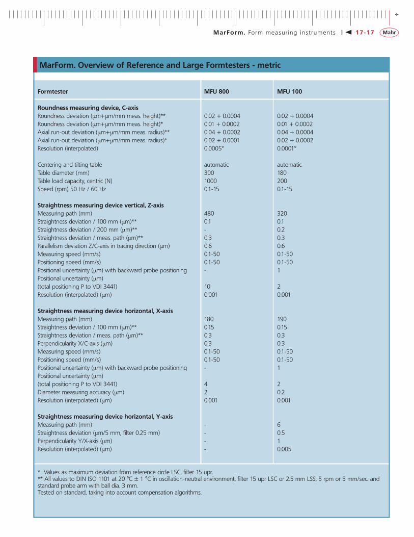
MarForm. Form measur ing ins t ruments 17-17
Formtester MFU 800 MFU 100
Roundness measuring device, C-axisRoundness deviation (µm+µm/mm meas. height)** 0.02 + 0.0004 0.02 + 0.0004Roundness deviation (µm+µm/mm meas. height)* 0.01 + 0.0002 0.01 + 0.0002Axial run-out deviation (µm+µm/mm meas. radius)** 0.04 + 0.0002 0.04 + 0.0004Axial run-out deviation (µm+µm/mm meas. radius)* 0.02 + 0.0001 0.02 + 0.0002Resolution (interpolated) 0.0005° 0.0001°
Centering and tilting table automatic automaticTable diameter (mm) 300 180Table load capacity, centric (N) 1000 200Speed (rpm) 50 Hz / 60 Hz 0.1-15 0.1-15
Straightness measuring device vertical, Z-axisMeasuring path (mm) 480 320Straightness deviation / 100 mm (µm)** 0.1 0.1Straightness deviation / 200 mm (µm)** - 0.2Straightness deviation / meas. path (µm)** 0.3 0.3Parallelism deviation Z/C-axis in tracing direction (µm) 0.6 0.6Measuring speed (mm/s) 0.1-50 0.1-50Positioning speed (mm/s) 0.1-50 0.1-50Positional uncertainty (µm) with backward probe positioning - 1Positional uncertainty (µm) (total positioning P to VDI 3441) 10 2Resolution (interpolated) (µm) 0.001 0.001
Straightness measuring device horizontal, X-axisMeasuring path (mm) 180 190Straightness deviation / 100 mm (µm)** 0.15 0.15Straightness deviation / meas. path (µm)** 0.3 0.3Perpendicularity X/C-axis (µm) 0.3 0.3Measuring speed (mm/s) 0.1-50 0.1-50Positioning speed (mm/s) 0.1-50 0.1-50Positional uncertainty (µm) with backward probe positioning - 1Positional uncertainty (µm)(total positioning P to VDI 3441) 4 2Diameter measuring accuracy (µm) 2 0.2Resolution (interpolated) (µm) 0.001 0.001
Straightness measuring device horizontal, Y-axis Measuring path (mm) - 6Straightness deviation (µm/5 mm, filter 0.25 mm) - 0.5Perpendicularity Y/X-axis (µm) - 1Resolution (interpolated) (µm) - 0.005
* Values as maximum deviation from reference circle LSC, filter 15 upr.** All values to DIN ISO 1101 at 20 °C ± 1 °C in oscillation-neutral environment, filter 15 upr LSC or 2.5 mm LSS, 5 rpm or 5 mm/sec. andstandard probe arm with ball dia. 3 mm.Tested on standard, taking into account compensation algorithms.
MarForm. Overview of Reference and Large Formtesters - metric
-
MarForm. Form Measur ing Ins t ruments17-18
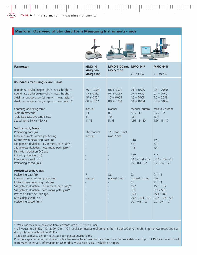
MarForm. Overview of Standard Form Measuring Instruments - inch
Formtester MMQ 10 MMQ 6100 ext. MMQ 44 R MMQ 44 RMMQ 100 MMQ 6200MMQ 6100 Z = 13.8 in Z = 19.7 in
Roundness measuring device, C-axis
Roundness deviation (µin+µin/in meas. height)** 2.0 + 0.024 0.8 + 0.020 0.8 + 0.020 0.8 + 0.020Roundness deviation (µin+µin/in meas. height)* 1.0 + 0.012 0.4 + 0.010 0.4 + 0.010 0.4 + 0.010Axial run-out deviation (µin+µin/in meas. radius)** 1.6 + 0.024 1.6 + 0.008 1.6 + 0.008 1.6 + 0.008Axial run-out deviation (µin+µin/in meas. radius)* 0.8 + 0.012 0.8 + 0.004 0.8 + 0.004 0.8 + 0.004
Centering and tilting table manual manual manual / autom. manual / autom.Table diameter (in) 6.3 8.7 8.7 / 11.2 8.7 / 11.2Table load capacity, centric (lbs) 44 134 134 134Speed (rpm) 50 Hz / 60 Hz 5 / 6 5 / 6 1.66 - 5 - 10 1.66 - 5 - 10
Vertical unit, Z-axisPositioning path (in) 11.8 manual 12.5 man. / mot.Manual or motor-driven positioning manual man. / mot.Motor-driven measuring path (in) - - 13.8 19.7Straightness deviation / 3.9 in meas. path (µin)** - - 5.9 5.9Straightness deviation / total meas. path (µin)** - - 11.8 15.7Parallelism deviation Z/C-axisin tracing direction (µin) - - 19.7 31.5Measuring speed (in/s) - - 0.02 - 0.04 - 0.2 0.02 - 0.04 - 0.2Positioning speed (in/s) - - 0.2 - 0.4 - 1.2 0.2 - 0.4 - 1.2
Horizontal unit, X-axisPositioning path (in) 7 8.8 7.1 7.1 / 11Manual or motor-driven positioning manual manual / mot. manual or mot. mot.Motor-driven measuring path (in) - - 7.1 7.1 / 11Straightness deviation / 3.9 in meas. path (µin)** - - 15.7 15.7 / 19.7Straightness deviation / total meas. path (µin)** - - 31.5 31.5 / 59.0Perpendicularity X/C-axis (µin) - - 39.4 39.4 / 78.7Measuring speed (in/s) - - 0.02 - 0.04 - 0.2 0.02 - 0.04 - 0.2Positioning speed (in/s) - - 0.2 - 0.4 - 1.2 0.2 - 0.4 - 1.2
* Values as maximum deviation from reference circle LSC, filter 15 upr.** All values to DIN ISO 1101 at 20 °C ± 1 °C in oscillation-neutral environment, filter 15 upr LSC or 0.1 in LSS, 5 rpm or 0.2 in/sec. and stan-dard probe arm with ball dia. 0.118 in.Tested on standard, taking into account compensation algorithms.Due the large number of possibilities, only a few examples of machines are given here. Technical data about "your" MMQ can be obtainedfrom Mahr on request. Information on US models MMQ 6xxx is also available on request.
+
MarForm. Form Measur ing Ins t ruments 17-19
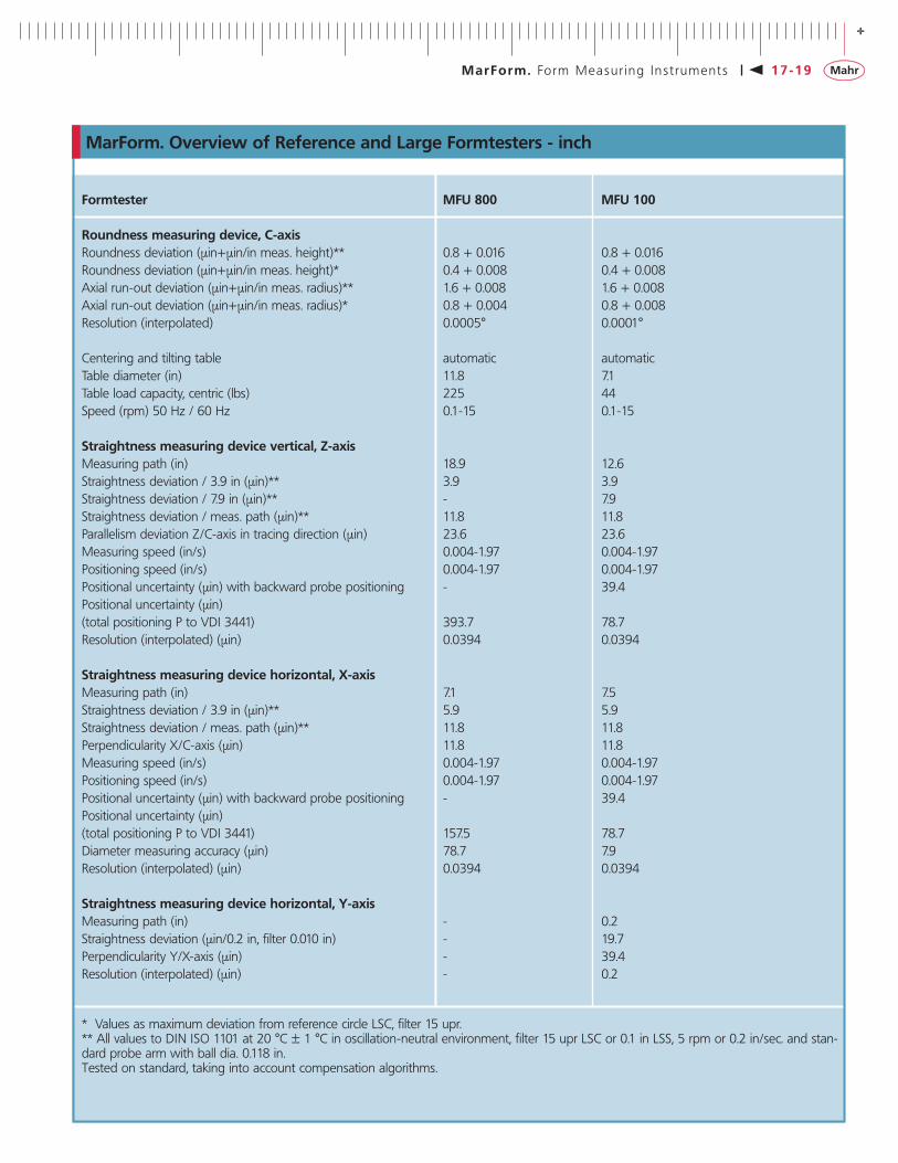
Formtester MFU 800 MFU 100
Roundness measuring device, C-axisRoundness deviation (µin+µin/in meas. height)** 0.8 + 0.016 0.8 + 0.016Roundness deviation (µin+µin/in meas. height)* 0.4 + 0.008 0.4 + 0.008Axial run-out deviation (µin+µin/in meas. radius)** 1.6 + 0.008 1.6 + 0.008Axial run-out deviation (µin+µin/in meas. radius)* 0.8 + 0.004 0.8 + 0.008Resolution (interpolated) 0.0005° 0.0001°
Centering and tilting table automatic automaticTable diameter (in) 11.8 7.1Table load capacity, centric (lbs) 225 44Speed (rpm) 50 Hz / 60 Hz 0.1-15 0.1-15
Straightness measuring device vertical, Z-axisMeasuring path (in) 18.9 12.6Straightness deviation / 3.9 in (µin)** 3.9 3.9Straightness deviation / 7.9 in (µin)** - 7.9Straightness deviation / meas. path (µin)** 11.8 11.8Parallelism deviation Z/C-axis in tracing direction (µin) 23.6 23.6Measuring speed (in/s) 0.004-1.97 0.004-1.97Positioning speed (in/s) 0.004-1.97 0.004-1.97Positional uncertainty (µin) with backward probe positioning - 39.4Positional uncertainty (µin) (total positioning P to VDI 3441) 393.7 78.7Resolution (interpolated) (µin) 0.0394 0.0394
Straightness measuring device horizontal, X-axisMeasuring path (in) 7.1 7.5Straightness deviation / 3.9 in (µin)** 5.9 5.9Straightness deviation / meas. path (µin)** 11.8 11.8Perpendicularity X/C-axis (µin) 11.8 11.8Measuring speed (in/s) 0.004-1.97 0.004-1.97Positioning speed (in/s) 0.004-1.97 0.004-1.97Positional uncertainty (µin) with backward probe positioning - 39.4Positional uncertainty (µin)(total positioning P to VDI 3441) 157.5 78.7Diameter measuring accuracy (µin) 78.7 7.9Resolution (interpolated) (µin) 0.0394 0.0394
Straightness measuring device horizontal, Y-axis Measuring path (in) - 0.2Straightness deviation (µin/0.2 in, filter 0.010 in) - 19.7Perpendicularity Y/X-axis (µin) - 39.4Resolution (interpolated) (µin) - 0.2
* Values as maximum deviation from reference circle LSC, filter 15 upr.** All values to DIN ISO 1101 at 20 °C ± 1 °C in oscillation-neutral environment, filter 15 upr LSC or 0.1 in LSS, 5 rpm or 0.2 in/sec. and stan-dard probe arm with ball dia. 0.118 in.Tested on standard, taking into account compensation algorithms.
MarForm. Overview of Reference and Large Formtesters - inch

-
MarForm. Form Measur ing Ins t ruments17-20
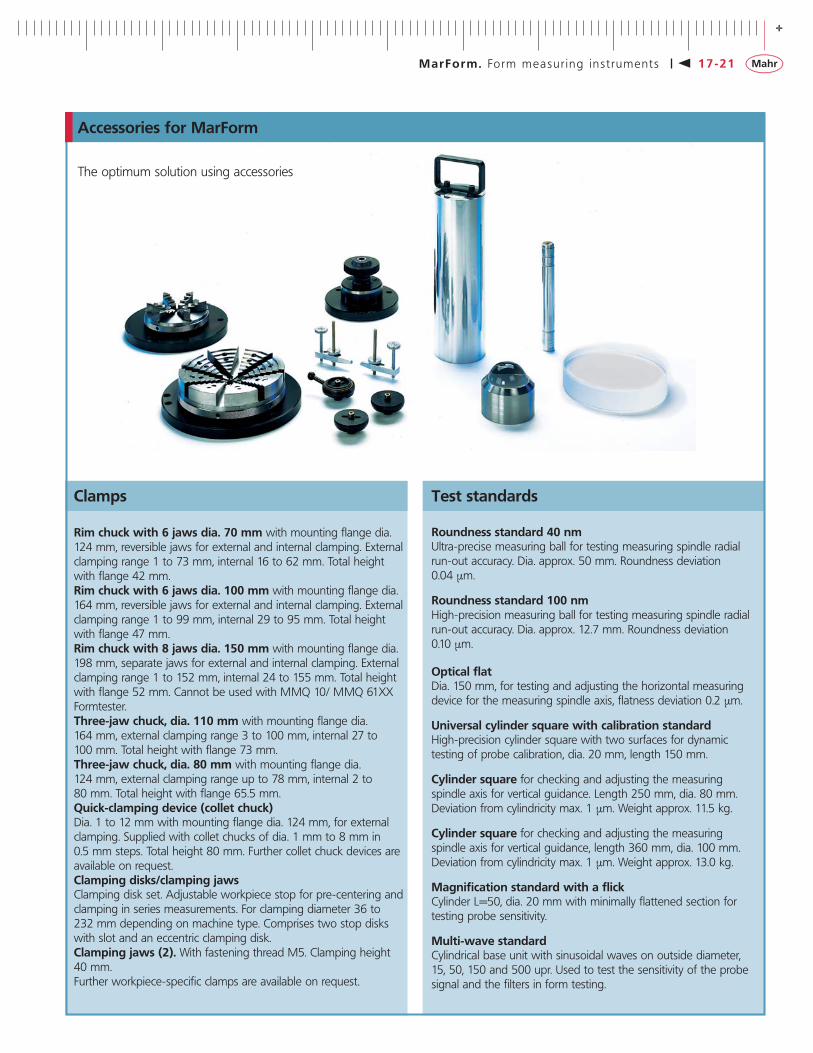
Accessories for MarForm
Probe T2W
The optimum solution using accessories
The inductive T2W probe is a universal device. The fact that theprobe arm can be moved in a range of 180° and that there are avariety of clamping possibilities for the probe means that measure-ments can also be performed on difficult to access areas. You cancombine easily exchangeable probe arms with a variety of styli inorder to adapt the probe to the relevant measuring tasks or work-pieces.
T2W probe with probe arm moveable around 180°• Measuring range ± 1000 µm/± 0.0394 “• Measuring force adjustable from 0.05 to 0.5 N• Measuring direction switchable• Exchangeable probe arm• Mechanical overload protection• Free travel limitation adjustable in contacting direction• Clamping shaft dia. 8 mm/0.351 “
Motor-driven T7W probe
The T7W probe is fitted with a motor-driven rotational axis. Itmakes it possible to move the probe arm gradually to the desiredcontacting position. This means that measurements can be per-formed on cylindrical surfaces and end faces. As a zero position probe, the T7W is also able to automatically switch between internal and external measurements or between end face measurements from top to bottom without operator intervention.Fully automatic measurement processes on complex workpiecescan be carried out without operator intervention. The probe arms of the T7W are exchangeable. Its motor-driven rotational axis enables the construction of "multi-point probe arms" - i.e. probearms with a variety of contacting elements - making it possible toswitch between different stylus ball geometries within a singlemeasurement run.
Motor-driven T7W probe with probe arm moveable around 360° for MMQ 44, MMQ 44 CNC and MFU 100
• Total range of 2000 µm/0.0788 “• Zero probe working range ± 500 µm/± 0.0197 “• Measuring force adjustable from 0.01 to 0.2 N• Two-way measuring direction• Contacting angle freely selectable in 1° steps• 360° adjustable (motor-driven)• Probe arms easily exchangeable (magnetic mount)• Flexible multi-point probe possible• Probe arm module with adjustment device available• Mechanical and electrical overload protection
+
MarForm. Form measur ing ins t ruments 17-21
Roundness standard 40 nmUltra-precise measuring ball for testing measuring spindle radial run-out accuracy. Dia. approx. 50 mm. Roundness deviation 0.04 µm.
Roundness standard 100 nmHigh-precision measuring ball for testing measuring spindle radialrun-out accuracy. Dia. approx. 12.7 mm. Roundness deviation 0.10 µm.
Optical flatDia. 150 mm, for testing and adjusting the horizontal measuringdevice for the measuring spindle axis, flatness deviation 0.2 µm.
Universal cylinder square with calibration standardHigh-precision cylinder square with two surfaces for dynamictesting of probe calibration, dia. 20 mm, length 150 mm.
Cylinder square for checking and adjusting the measuring spindle axis for vertical guidance. Length 250 mm, dia. 80 mm.Deviation from cylindricity max. 1 µm. Weight approx. 11.5 kg.
Cylinder square for checking and adjusting the measuring spindle axis for vertical guidance, length 360 mm, dia. 100 mm.Deviation from cylindricity max. 1 µm. Weight approx. 13.0 kg.
Magnification standard with a flickCylinder L=50, dia. 20 mm with minimally flattened section fortesting probe sensitivity.
Multi-wave standardCylindrical base unit with sinusoidal waves on outside diameter, 15, 50, 150 and 500 upr. Used to test the sensitivity of the probe signal and the filters in form testing.
Accessories for MarForm
The optimum solution using accessories
Clamps
Rim chuck with 6 jaws dia. 70 mm with mounting flange dia.124 mm, reversible jaws for external and internal clamping. Externalclamping range 1 to 73 mm, internal 16 to 62 mm. Total heightwith flange 42 mm.Rim chuck with 6 jaws dia. 100 mm with mounting flange dia.164 mm, reversible jaws for external and internal clamping. Externalclamping range 1 to 99 mm, internal 29 to 95 mm. Total heightwith flange 47 mm.Rim chuck with 8 jaws dia. 150 mm with mounting flange dia.198 mm, separate jaws for external and internal clamping. Externalclamping range 1 to 152 mm, internal 24 to 155 mm. Total heightwith flange 52 mm. Cannot be used with MMQ 10/ MMQ 61XXFormtester.Three-jaw chuck, dia. 110 mm with mounting flange dia. 164 mm, external clamping range 3 to 100 mm, internal 27 to 100 mm. Total height with flange 73 mm.Three-jaw chuck, dia. 80 mm with mounting flange dia. 124 mm, external clamping range up to 78 mm, internal 2 to 80 mm. Total height with flange 65.5 mm.Quick-clamping device (collet chuck)Dia. 1 to 12 mm with mounting flange dia. 124 mm, for externalclamping. Supplied with collet chucks of dia. 1 mm to 8 mm in 0.5 mm steps. Total height 80 mm. Further collet chuck devices areavailable on request.Clamping disks/clamping jawsClamping disk set. Adjustable workpiece stop for pre-centering andclamping in series measurements. For clamping diameter 36 to 232 mm depending on machine type. Comprises two stop diskswith slot and an eccentric clamping disk.Clamping jaws (2). With fastening thread M5. Clamping height 40 mm.Further workpiece-specific clamps are available on request.
Test standards
-
MarForm. Form Measur ing Ins t ruments17-22
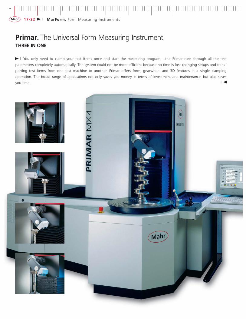
You only need to clamp your test items once and start the measuring program - the Primar runs through all the test
parameters completely automatically. The system could not be more efficient because no time is lost changing setups and trans-
porting test items from one test machine to another. Primar offers form, gearwheel and 3D features in a single clamping
operation. The broad range of applications not only saves you money in terms of investment and maintenance, but also saves
you time.
Primar. The Universal Form Measuring InstrumentTHREE IN ONE

+
MarForm. Form Measur ing Ins t ruments 17-23
Primar MX 4
Features
The Primar dynamically scans axis-symmetrical workpieces for form and positional deviations. It provides µm-accurate measuringdata quickly for your production needs.
When used with the CNC tilting and centering table, the Primar isable to perform true form measurements. With this type ofmeasurement, only one axis (the high-precision C spindle) is movedto record the data, thus minimizing the measuring uncertainty.Thousands of 3D measurement values are recorded. As a result ofprior CNC-controlled tilting and leveling to align the workpiece, themeasurement is completely without error in accordance with theAbbe principle.
The four measuring axes of the Primar are designed such thateven large and heavy workpieces can be measured.
• X-axis 300 mm/11.8 “• Y-axis 600 mm/23.6 “• Z-axis 700 mm/27.6 “
The easily accessible turntable is generously proportioned andmakes it easy to load test items.
The Primar enables you to perform a wide range of measuringtasks more cost-efficiently than ever before. It is the first unit capable of checking eccentric parts with formtester accuracy. This is thanks to easy-to-use family programs for gears, geared tools, bevel gears, camshafts, crankshafts, pistons and connecting rods or customized measuring programs developed specifically for yourworkpiece.
The Primar can be used in the following applications:• Mechanical and electrical engineering: Gearwheels, rotors,
spindles, ball bearing cages, spur gear shafts, involute gear teeth, hollow shafts with internal toothing, pinion shafts, planetary gears, ring gears, control valves, tappets, camshafts, connecting rods
• Automotive construction: Pistons, steering components, axle and shaft journals, propeller shafts, gearwheels, worms, bevel gears, etc.
• Customized axis-symmetrical workpieces
Primar measuring station componentsThe Primar is customized to your specific requirements and work-pieces. The machine concept allows you to add on extra options.These, like the software, are modular.• MarForm Primar MX 4 XXL• MarForm Primar MX 4 CNC• Center support for fixing between centers
A successful combination of Formtester and Polar Coordinate Measuring Instrument
-
MarForm. Form Measur ing Ins t ruments17-24
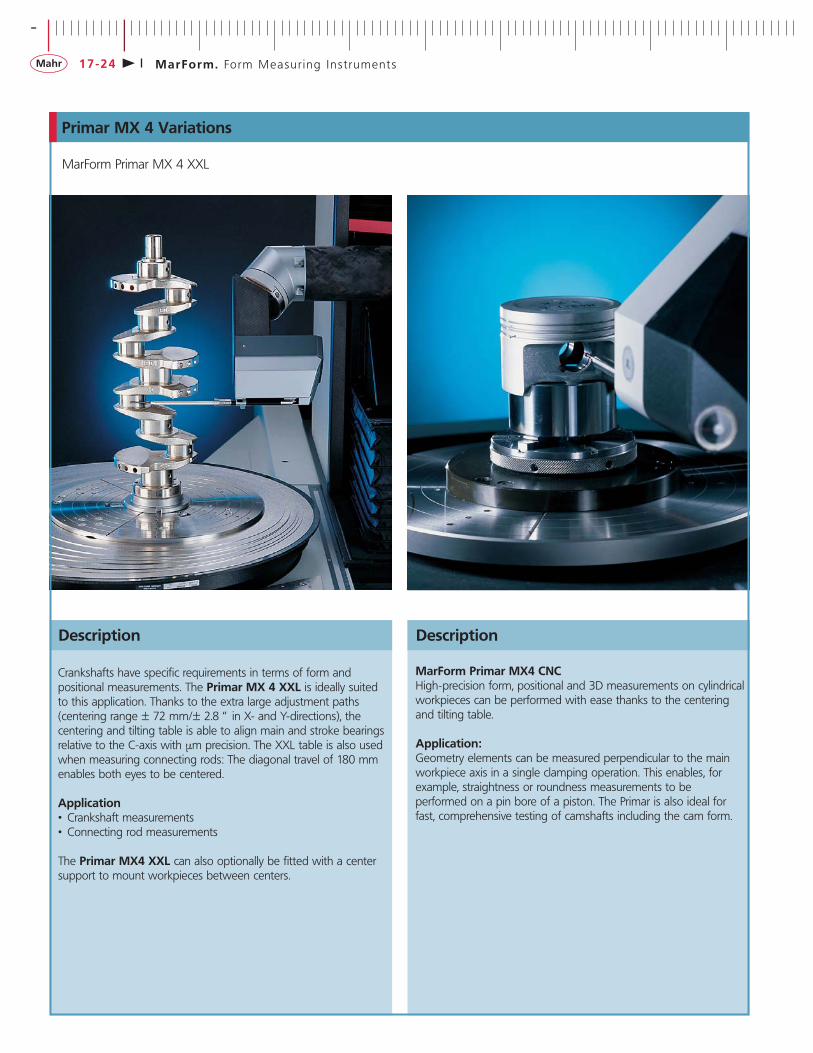
Primar MX 4 Variations
Description
Crankshafts have specific requirements in terms of form and positional measurements. The Primar MX 4 XXL is ideally suitedto this application. Thanks to the extra large adjustment paths (centering range ± 72 mm/± 2.8 “ in X- and Y-directions), the centering and tilting table is able to align main and stroke bearingsrelative to the C-axis with µm precision. The XXL table is also usedwhen measuring connecting rods: The diagonal travel of 180 mmenables both eyes to be centered.
Application• Crankshaft measurements• Connecting rod measurements
The Primar MX4 XXL can also optionally be fitted with a centersupport to mount workpieces between centers.
MarForm Primar MX4 CNCHigh-precision form, positional and 3D measurements on cylindricalworkpieces can be performed with ease thanks to the centeringand tilting table.
Application:Geometry elements can be measured perpendicular to the mainworkpiece axis in a single clamping operation. This enables, forexample, straightness or roundness measurements to be performed on a pin bore of a piston. The Primar is also ideal forfast, comprehensive testing of camshafts including the cam form.
MarForm Primar MX 4 XXL
Description

+
MarForm. Form Measur ing Ins t ruments 17-25
Primar software solutionsThe process of creating a measuring program and measuring workpieces must be fast and not involve a lot of programming. This is no problem with the Primar family program. It defines eachnew measuring program using masks. The operator only has toenter the geometry of the workpieces and select the required features. The part is then measured automatically. It also respondsquickly and flexibly in the case of measurement of part families orrapid changes. It is available for the following:
• Crankshafts• Camshafts• Pistons• Shaving gears• Hobs• Bevel gears• Spur gears• Worms
Primar Software Solutions
Description
Family program for crankshafts
When used in combination with an XXL centering and tilting table on the C-axis, Primar isa high-performance measuring station for crank-shafts. Form, position and 3D features can be measured in a single clamping operation. The family program offers a large number of features at main and stroke bearings and at theflange and journal of the crankshaft. The formfeatures on the workpiece are always measuredin formtester mode. This ensures maximum accuracy for the results. To perform the measurements, the main and stroke bearings areautomatically aligned with the C-axis of the measuring instrument. The large number of measuring points provides the basis for the highquality of the measurement results. This results inhigh-precision workpiece axes.
Crankshafts
Camshafts
measuring station for camshafts and the familyprogram offers everything you will need for fast,efficient and comprehensive camshaft measure-ment. The nominal cam form can be imported as a file. The probe moves along this nominalcam contour. The distance between the measuring points is kept constant. This meansthat you get a detailed view of your cam profileswith your desired tolerance bands.
Pistons
Connecting rods
There are also application programs for the following:• Connecting rods• Engine blocks• Cylinder heads• Other workpieces
Family program for camshaftsTo use the family program for camshafts, youneed both a Formtester that records the featuresat the bearing points and, in order to measure the cam form, a continuous-path control systemin combination with low contacting forces andrecording of as many measuring points as possible. The Primar offers a simple solution toboth these tasks. The combination of the
Family program for pistonsThe family program makes the Primar the idealmeasuring station for pistons. The workpiece isaligned with the piston bore. Ovality, meridianform, diameter, the pin bore of the piston and the grooves are measured in the workpiece coordinate system. The measurements are output in piston-specific records as a graphic and as results tables.
Family program for connecting rodsWhen used in combination with the XXL cente-ring and tilting table, the Primar can be utilized to its full benefit with this workpiece. The work-piece is measured in its entirety. The large andsmall eyes are positioned automatically into the C machine axis and all the form features are measured in form mode with maximum precision. Further features such as diameter,distance, thickness and the set of teeth are measured according to the drawing requirements in the same clamping operation.Primar is thus able to perform an evaluation ofthe entire workpiece in a single clamping operation and offers unique determination ofdatum elements. The evaluation results are available in tabular and graphic form. The universal clamp enables you to quickly change to other conrod types by a simple adjustment of the workpiece supports.


![CITA: Classical, a trope is a deviation, a ... - Mara SerranoCITA: Classical, a trope is a deviation, a turning, some alteration of the ...denominated. CITA desde Even [...] form se](https://static.fdocuments.us/doc/165x107/5e301875c2088b3163173474/cita-classical-a-trope-is-a-deviation-a-mara-cita-classical-a-trope-is.jpg)