
IMPROVEMENT OF: SCWQP – TUNNEL STORAGE
406
CITY OF SEATTLE Seattle Public Utilities IMPROVEMENT OF: SCWQP – TUNNEL STORAGE Project Manual – Volume 5 of 5 (Division 40 through Division 44) FUNDED BY: DWF/ Washington State Department of Ecology/WIFIA PW#: 2018-018 ORDINANCE #: 125475 Advertise: March 6, 2019 Bids Open: May 1, 2019 SEATTLE, WASHINGTON
Transcript of IMPROVEMENT OF: SCWQP – TUNNEL STORAGE

CITY OF SEATTLE
Seattle Public Utilities
IMPROVEMENT OF: SCWQP – TUNNEL STORAGE
Project Manual – Volume 5 of 5
(Division 40 through Division 44)
FUNDED BY: DWF/ Washington State Department of Ecology/WIFIA PW#: 2018-018 ORDINANCE #: 125475
Advertise: March 6, 2019
Bids Open: May 1, 2019
SEATTLE, WASHINGTON

TABLE OF CONTENTS SECTION 00 01 10 SCWQP – TUNNEL STORAGE Page I
VOLUME 5 – DIVISION 40 THROUGH DIVISION 44
DIVISION 40 – PROCESS INTEGRATION
Section 40 05 01 – Piping Systems
Section 40 05 06.16 – Piping Connections
Section 40 05 06.23 – Expansion Joints and Flexible Metal Hose
Section 40 05 06.33 – Piping Appurtenances
Section 40 05 07 – Hangers and Supports for Process Piping
Section 40 05 07.13 – Seismic Restraints for Piping
Section 40 05 07.16 – Expansion Control for Piping
Section 40 05 17 – Copper Process Pipe and Tubing
Section 40 05 19 – Ductile Iron Process Pipe
Section 40 05 22 – Hydraulic Service Stainless Steel Pipe
Section 40 05 23 – Stainless Steel Process Pipe and Tubing
Section 40 05 24 – Steel Process Pipe
Section 40 05 31 – Thermoplastic Process Pipe
Section 40 05 33.13 – HDPE Pipe for Air Service
Section 40 05 49.16 – FRP Encapsulated Steel Bulkhead Gates
Section 40 05 57 – Electric Gate Actuators and Appurtenances
Section 40 05 58 – Electro-Hydraulic Actuators
Section 40 05 59.23 – Stainless Steel Slide Gates
Section 40 05 61.16 – Gate Valves
Section 40 05 61.43 – Knife Gate Valves
Section 40 05 62.16 – Eccentric Plug Valves for Liquid Service
Section 40 05 65.23 – Swing Check Valves
Section 40 05 71.33 – Flap Gates
Section 40 42 00 – Insulation for Exposed Piping and Equipment
Section 40 61 13 – Process Control System General Provisions
Section 40 61 13A – Loop Check Out Sheet

TABLE OF CONTENTS SECTION 00 01 10 SCWQP – TUNNEL STORAGE Page J
Section 40 61 13B – Instrument Certification Sheet
Section 40 61 13C – Final Control Element Certification Sheet
Section 40 61 96 – Process Control Descriptions
Section 40 61 96A – Input Output List
Section 40 63 00 – Control System Equipment
Section 40 67 00 – Control System Equipment Panels and Racks
Section 40 70 00 – Instrumentation for Process Systems
Section 40 78 00 – Panel Mounted Instruments
Section 40 78 56 – Isolators, Intrinsically-Safe Barriers, and Surge Suppressors
DIVISION 41 – MATERIAL PROCESSING AND HANDLING EQUIPMENT
Section 41 22 00 – Cranes and Hoists
DIVISION 43 – PROCESS GAS AND LIQUID HANDLING, PURIFICATION, AND STORAGE EQUIPMENT
Section 43 05 11 – General Requirements for Equipment
Section 43 05 13 – Rigid Equipment Mounts
Section 43 05 18 – Vibration Isolation Systems
Section 43 05 21 – Common Motor Requirements for Equipment
Section 43 23 80.11 – Drypit Submersible Wastewater Pumps - Constant Speed
Section 43 41 45.16 – Fiberglass Reinforced Plastic Tanks for Activated Carbon
DIVISION 44 - POLLUTION AND WASTE CONTROL EQUIPMENT
Section 44 31 14 – Grease Filter / Mist Eliminator
Section 44 31 16 – Activated Carbon Adsorption Odor Control Media
END OF SECTION 00 01 10

PIPING SYSTEMS SECTION 40 05 01
SCWQP – TUNNEL STORAGE Page 1
PART 1 - GENERAL
1.01 SECTION INCLUDES
A. Scope:
1. General: This Section specifies process piping and general requirements for piping systems. Detailed specifications for the components listed on the Piping Specification Sheets (PIPESPEC) as described in paragraph 3.08 are referenced from this Section. Use this Section in conjunction with the referenced sections. Except where alternate provisions are indicated in referenced specifications, the requirements of this Section shall apply to all piping systems listed herein.
2. Contractor Design of Piping Systems: In addition to materials and labor required to construct piping systems, Contractor shall provide professional engineering services for a piping system design engineer (hereinafter and in all referenced sections the "Design Professional") for the design and inspection of piping systems work. The Design Professional shall provide the final design, inspection, and certification for the piping supports and seismic restraints as defined in paragraph 40 05 01-1.04.B, in the Drawings, and the following sections:
a. Pipe hangers and supports and inspection requirements are specified in Section 40 05 07 – Hangers and Supports for Process Piping.
b. Seismic restraints are specified in Section 40 05 07.13 – Seismic Restraints for Piping.
c. Pipe expansion control systems are specified in Section 40 05 07.16 – Expansion Control for Piping.
1.02 REFERENCE STANDARDS
A. References: This section contains references to the following documents. They are a part of this section as specified and modified. Where a referenced document contains references to other standards, those documents are included as references under this section as if referenced directly. In the event of conflict between the requirements of this section and those of the listed documents, the requirements of this section shall prevail. Unless otherwise specified, references to documents shall mean the documents in effect at the time of Advertisement for Bids or Invitation to Bid (or on the effective date of the Agreement if there were no Bids). If referenced documents have been discontinued by the issuing organization, references to those documents shall mean the replacement documents issued or otherwise identified by that organization or, if there are no replacement documents, the last version of the document before it was discontinued.
Reference Title
ANSI A13.1 Scheme for the Identification of Piping Systems
ANSI B1.20.1 Pipe Threads, General Purpose (Inch)
ANSI B16.1 Cast Iron Pipe Flanges and Flanged Fittings Class 25, 125, 250, and 800
ANSI B16.3 Malleable Iron Threaded Fittings Class 150 and 300
ANSI B16.5 Pipe Flanges and Flanged Fittings

PIPING SYSTEMS SECTION 40 05 01
SCWQP – TUNNEL STORAGE Page 2
Reference Title
ANSI B16.9 Factory-Made Wrought Steel Buttwelding Fittings
ANSI B16.11 Forged Steel Fittings, Socket Welding and Threaded
ANSI B16.12 Cast Iron Threaded Drainage Fittings
ANSI B16.22 Wrought Copper and Copper Alloy Solder Joint Pressure Fittings
ANSI B31.3 Chemical Plant and Petroleum Refinery Piping
ASME Section IX Boiler and Pressure Vessel Code; Welding and Brazing Qualifications
ASTM A53 Pipe, Steel, Black and Hot Dipped, Zinc-Coated Welded and Seamless
ASTM A74 Cast Iron Soil Pipe and Fittings
ASTM A105/A105M Forgings, Carbon Steel, for Piping Components
ASTM A106 Seamless Carbon Steel Pipe for High-Temperature Service
ASTM A126 Standard Specification for Gray Iron Castings for Valves, Flanges, and Pipe Fittings
ASTM A234/A234M Pipe Fittings of Wrought Carbon Steel and Alloy Steel for Moderate and Elevated Temperatures
ASTM A312/A312M Seamless and Welded Austenitic Stainless Steel Pipe
ASTM A403/A403M Wrought Austenitic Stainless Steel Piping Fittings
ASTM A536 Ductile Iron Castings
ASTM B88 Seamless Copper Water Tube
ASTM C564 Rubber Gaskets for Cast Iron Soil Pipe and Fittings
ASTM D1784 Rigid Poly (Vinyl Chloride) (PVC) Compounds and Chlorinated Poly(Vinyl Chloride) (CPVC) Compounds
ASTM D1785 Poly (Vinyl Chloride) (PVC) Plastic Pipe, Schedules 40, 80, and 120
ASTM D2241 Poly (Vinyl Chloride) (PVC) Plastic Pipe (SDR-PR)
ASTM D2665 Poly (Vinyl Chloride) (PVC) Plastic Drain, Waste, and Vent Pipe and Fittings
ASTM D3034 Standard Specification for Type PSM Poly (Vinyl Chloride) (PVC) Sewer Pipe and Fittings
ASTM D4174 Cleaning, Flushing, and Purification of Petroleum Fluid Hydraulic Systems
ASTM D4101 Propylene Plastic Injection and Extrusion Materials
AWWA C105 Polyethylene Encasement for Ductile-Iron Piping for Water and Other Liquids
AWWA C110 Ductile-Iron and Gray-Iron Fittings, 3 Inch Through 48 Inch, for Water and Other Liquids
AWWA C111 Rubber-Gasket Joints for Ductile-Iron and Gray-Iron Pressure Pipe and Fittings
AWWA C115 Flanged Ductile-Iron and Gray-Iron Pipe with Threaded Flanges
AWWA C151 Ductile-Iron Pipe, Centrifugally Cast in Metal Molds or Sand-Lined Molds, for Water or Other Liquids
AWWA C200 Steel Water Pipe 6 Inches and Larger
AWWA C206 Field Welding of Steel Water Pipe
AWWA C207 Steel Pipe Flanges for Waterworks Services--Sizes 4 In. through 144 In.
AWWA C208 Dimensions for Fabricated Steel Water Pipe Fittings

PIPING SYSTEMS SECTION 40 05 01
SCWQP – TUNNEL STORAGE Page 3
Reference Title
AWWA C209 Cold-Applied Tape Coating for Special Sections, Connections, and Fittings for Steel Water Pipelines
AWWA C214 Tape Coating Systems for the Exterior of Steel Water Pipelines
AWWA C600 Installation of Ductile-Iron Water Mains and Their Appurtenances
AWWA C651 Disinfecting Water Mains
AWWA C900 Polyvinyl Chloride (PVC) Pressure Pipe, 4 Inches Through 12 Inches, for Water
AWWA M11 Steel Pipe--A Guide for Design and Installation
CISPI 301 Specification Data for Hubless Cast Iron Sanitary System with No-Hub Pipe and Fittings
MIL-H-13528B Hydrochloric Acid, Inhibited, Rust Removing
MIL-STD-810C Environmental Test Methods
SAE J1227 Assessing Cleanliness of Hydraulic Fluid Power Components and Systems
UPC Uniform Plumbing Code
1.03 DEFINITIONS
A. Definitions:
1. Pressure terms used in this Section and elsewhere in Division 40 are defined as follows:
a. Maximum: The greatest continuous pressure at which the piping system operates.
b. Test: The hydrostatic pressure used to determine system acceptance.
1.04 SUBMITTALS
A. Procedures: Section 01 33 10 – Submittals.
B. A copy of this specification section, with addendum updates included, and all referenced and applicable sections, with each paragraph check-marked to indicate compliance or marked to indicate requested deviations.
C. Submittal Items:
1. A copy of this Section, addendum updates included, with each paragraph check-marked to indicate compliance or marked to indicate requested deviations from Section requirements.
2. Qualifications of the Design Professional charged with design, inspection and certification of pipe hangers and supports and seismic restraint; provide educational background, proof of registration, proof of insurance and previous experience in performing this type of work. No further submittals under this or any related section will be considered until the Design Professional’s qualifications have been reviewed and accepted by the Engineer.

PIPING SYSTEMS SECTION 40 05 01
SCWQP – TUNNEL STORAGE Page 4
3. Drawings for structural attachments, pipe supports and seismic restraints as specified in this Section, Section 40 05 07 – Hangers and Supports for Process Piping, Section 40 05 07.13 – Seismic Restraints for Piping, and Section 40 05 07.16 – Expansion Control for Piping. Drawings shall be arranged by piping system and area and sealed by the Design Professional.
4. Manufacturer’s product literature on each bend, coupling, fitting, bolt, gasket, restraint or other item provided pursuant to this Section.
5. Piping layout drawings, for both exposed and buried piping systems, depicting supports, locations of support, fittings and restraints, expansion joints, seismic restraint provisions, thrust restraint provisions and other pertinent information, including wall and floor penetrations, where applicable. Piping layout drawings shall include details of connections to new and existing equipment, piping and structures. Drawings shall be original layouts by the Contractor; photocopies of Contract Drawings are not acceptable. Identify the invert elevation of buried pipe at changes in slope, pipe crossings, and connections to structures on piping layout drawings in addition to providing coordinates for locating changes in horizontal alignment of buried pipe. Piping layout drawings shall be transmitted to the Construction Manager a minimum of 2 weeks prior to construction.
6. Calculations for structural attachments, pipe supports and seismic restraints as specified in this Section, Section 40 05 07 – Hangers and Supports for Process Piping, Section 40 05 07.13 – Seismic Restraints for Piping, and Section 40 05 07.16 – Expansion Control for Piping. Calculations shall be arranged by piping system and area and sealed by the Design Professional. The Design Professional shall affirm that loads on structures are within the load limits noted in Section 40 05 07.16 – Expansion Control for Piping.
7. Product data on piping materials.
1.05 PIPING SYSTEM DESIGN
A. Design Professional: Contractor shall provide professional engineering services (“Design Professional”) for the design and inspection of piping systems work. The design of these systems shall be the product of a professional engineer retained by the Contractor and currently licensed to practice in the State of Washington. This requirement shall not be construed as relieving the Contractor of overall responsibility for this portion of the work.
B. Piping System Design and Inspection:
1. The work of the Design Professional shall be complementary to the design elements specified in the Construction Documents, to provide complete piping system designs. The Design Professional’s inspection responsibilities also complement inspections by SPU. The division of responsibility for the final design, inspection, and certification of piping supports, seismic restraints, and expansion control as specified in the Contract Documents is as follows:
a. SPU:
1) Pipe material and thickness, test properties, and other properties.

PIPING SYSTEMS SECTION 40 05 01
SCWQP – TUNNEL STORAGE Page 5
2) Specialty pipe supports, bracing, or expansion control only where specifically shown on the Drawings.
3) Special inspections.
b. Design Professional:
1) Contractor fabrication/layout drawings for all piping (Section 40 05 01 – Piping Systems).
2) Pipe supports for all piping (Section 40 05 07 – Hangers and Supports for Process Piping).
3) Seismic bracing for all piping (Section 40 05 07.13 – Seismic Restraints for Piping).
4) Expansion and contraction design for all piping (Section 40 05 07.16 – Expansion Control for Piping).
5) General inspection for design and specification conformance
2. Where specific pipe supports, seismic restraints, and expansion control mechanisms are shown on the Drawings, they shall be used, coordinated with, and incorporated into the overall piping system design by the Design Professional.
3. The design standards for use by the Design Professional shall be selected from the following list. Others may be used upon written request by Design Professional and justification, through the Contractor, to the Engineer.
a. Process Piping and piping not otherwise specified - ANSI/ASME B31.3.
b. Building Services Piping - ANSI/ASME B31.9.
c. Fuel gas piping –NFPA 54 (ANSI Z223.1) National Fuel Gas Code and ANSI/ASME B31.1.
d. Steel water pipe - ANSI/ASME B31.3 (piping within the scope of AWWA M11, may be designed in accordance with AWWA M11).
4. Design of piping systems and appurtenances shall include, but not be limited to, consideration of and provisions for:
a. Piping support and restraint independent of equipment and no equipment supported loads exceeding equipment manufacturer’s requirements. Design Professional shall obtain maximum nozzle loads from the Contractor.
b. Piping shall be routed to provide access aisles free of obstruction and worker hazards. Unless otherwise noted or approved by the Engineer, the minimum clear space between equipment shall be 3 feet horizontally. Minimum vertical clearance shall be 7-feet above the floor or local grade at access aisles and egress paths.
c. Electrical bonding for all gas, fuel and pneumatic conveyance systems.
d. Dielectric separation, as specified.

PIPING SYSTEMS SECTION 40 05 01
SCWQP – TUNNEL STORAGE Page 6
5. Piping submittals by the Contractor shall include all elements of piping systems required for fabrication and construction, including those portions specified on the Drawings. Submittals shall depict couplings, restraint, anchorage, expansion control measures and other elements of the piping system. The Contractor’s Design Professional shall, as part of the submittal process, notify the Engineer if he/she believes any restraint or expansion element is incompatible with the overall piping system and its function.
6. Where a specific support, hanger guide, structural attachment, joint or seismic restraint detail for pipe or duct is shown, it indicates a required configuration or general arrangement to be developed by the Design Professional.
7. Fitting angles and vertical and horizontal pipe locations shall be determined by Contractor and depicted on piping layout Drawings.
8. Where the use of particular piping elements are required for expansion control or pipe flexibility they are specified on the Drawings. The Contractor’s pipe support and seismic restraint design shall not interfere with the function of anchorage, flexibility, and expansion control provisions.
PART 2 - PRODUCTS
2.01 PIPING MATERIALS
A. Materials:
1. Unless otherwise specified, piping materials, including pipe, gaskets, fittings, connection and joint assemblies, linings and coatings, shall be selected from those listed on the piping system specification sheets. Piping materials shall conform to detailed specifications for each type of pipe and piping appurtenance specified in other sections of Division 40.
2. New and existing piping is designated by service rather than pipe material. Existing pipe material types may not be the same as material types specified for new piping. Contractor shall investigate and provide suitable connections, including electrical isolation, as necessary.
B. Fittings and Coupling Compatibility: To assure uniformity and compatibility of piping components, fittings and couplings for grooved-end or shouldered-end piping systems shall be furnished by the same manufacturer.
C. Buried Piping:
1. All buried piping shall be fully-restrained systems. Where required, Design Professional shall size temporary and/or permanent thrust restraints. Restraint systems shall be designated to allow complete piping system disassembly without destructive measures.
2. Buried piping shall be provided as specified. Unless otherwise noted, materials specified in the piping specification sheets shall be used. Thicknesses specified in the piping specification sheets or referenced specifications shall be considered minimums. Excavation, installation and backfill shall be as specified.

PIPING SYSTEMS SECTION 40 05 01
SCWQP – TUNNEL STORAGE Page 7
2.02 PIPING IDENTIFICATION
A. Plastic Coding Markers:
1. Plastic markers for coding pipe shall conform to ANSI A13.1 and shall be as manufactured by W. H. Brady Company, Seton Name Plate Corporation, Marking Services Inc., or approved equal. Markers shall be the mechanically attached type that are easily removable; they shall not be the adhesive applied type. Markers shall consist of pressure sensitive legends applied to plastic backing which is strapped or otherwise mechanically attached to the pipe. Legend and backing shall be resistant to petroleum based oils and grease and shall meet criteria for humidity, solar radiation, rain, salt, fog and leakage fungus, as specified by MIL-STD-810C. Markers shall withstand a continuous operating temperature range of -40 degrees F to 180 degrees F. Plastic coding markers shall not be the individual letter type but shall be manufactured and applied in one continuous length of plastic.
2. Markers bearing the legends on the background colors specified in the PIPESPEC shall be provided in the following letter heights:
Outside Pipe Diameter,1 Inches
Letter Height, Inches
Less than 1-1/2 1/2
1-1/2 through 3 1-1/8
Greater than 3 2-1/4
1 Outside pipe diameter shall include insulation and jacketing.
3. In addition, pipe markers shall include uni- and bi-directional arrows in the same sizes as the legend. Legends and arrows shall be white on blue or red backgrounds and black on other specified backgrounds.
B. Plastic Tracer Tape:
1. Tracer tape shall be 6 inches wide, colored the same as the background colors as specified in this Section, and made of inert plastic material suitable for direct burial. Tape shall be capable of stretching to twice its original length and shall be as manufactured by Allen Systems, W. H. Brady Co., Seton Name Plate Corporation, Marking Services Inc., or approved equal.
2. Two messages shall be printed on the tape. The first message shall read "CAUTION ___ PIPE BURIED BELOW" with bold letters approximately 2 inches high. The blank shall be filled with the name of the piping system. The second message shall read "CALL____" with letters approximately 3/4 inch high. Both messages shall be printed at maximum intervals of 2 feet.
C. Magnetic Tracer Tape:
1. Polyethylene magnetic tracer tape shall be acid and alkali-resistant, 6 inches wide, 0.005 inch thick, and have 1500 psi strength and 140 percent elongation value. Tape shall be colored the same as the background colors as specified in this Section. Tape shall be as manufactured by Allen Systems, W. H. Brady Co., Seton Name Plate Corporation, Marking Services Inc., or approved equal.

PIPING SYSTEMS SECTION 40 05 01
SCWQP – TUNNEL STORAGE Page 8
2. Two messages shall be printed on the tape. The first message shall read "CAUTION ___ PIPE BURIED BELOW" with bold letters approximately 2 inches high. The blank shall be filled with the name of the piping system. The second message shall read "CALL____" with letters approximately 3/4 inches high. Both messages shall be printed at maximum intervals of 2 feet.
2.03 VALVES
A. Valves of the same size and service shall be provided by a single valve manufacturer. Packing shall be non-asbestos material. Actual length of valves shall be within 1/16 inch (plus or minus) of the manufacturer's specified length. Flanges shall meet the requirement of ANSI B16.5. Push-on and mechanical joints shall meet the requirements of AWWA C111.
2.04 PIPE AND VALVE COMPATIBILITY
A. Selected pipe and pipe end connections for valves, or other equipment, shall be fully compatible within each piping system. Coordinate the selection of pipe materials, linings and end connections so that valves operate properly over their entire range (e.g., sufficient disk clearance for butterfly valves). Selected end connections shall also be suitable for specified valve or equipment (e.g., wafer style valves or spectacle flanges shall be properly supported between flanges of equal inside diameter).
2.05 BONDING JUMPERS
A. Jumpers shall be plated, flexible copper braid with unplated copper ferrules for attachment to pipe flanges. Jumpers shall be rated for a 100-amp minimum. Provide Burndy Electrical, Type B series, or approved equal, and sufficient conductive, anti-oxidant compound (Burndy Electrical Penetrox series or approved substitute) to protect ferrules.
PART 3 - EXECUTION
3.01 INSTALLATION
A. Location:
1. The Drawings are, in part, diagrammatic. Piping shall be provided as specified except for adjustments to avoid architectural and structural features and shall be coordinated with electrical construction. Adjustments to piping shall be made to avoid interference and shown on the piping layout drawings.
B. Piping Sizes: Where the size of piping is not specified, the Contractor shall provide piping of the sizes required by UPC. Unless specified otherwise, small piping (less than 1 inch in diameter) required for services not described by UPC shall be 1/2 inch.
C. Pipe Support, Anchorage and Seismic Bracing:
1. General:
a. Piping shall be supported by anchor brackets, guides, saddles or hangers.

PIPING SYSTEMS SECTION 40 05 01
SCWQP – TUNNEL STORAGE Page 9
b. Acceptable types of supports, guides, saddles, expansion joints, flexible couplings, hangers and structure attachments for general pipe support, expansion/ contraction and for seismic bracing, as well as anchorage details, are referenced in Sections 40 05 07 – Hangers and Supports for Process Piping, 40 05 07.13 – Seismic Restraints for Piping, 40 05 07.16 – Expansion Control for Piping, and 40 05 06.16 – Piping Connections, or specified on the Drawings. Where a specific type of support or anchorage is indicated on the drawings, then only that type shall be used at that location.
c. Piping shall be vertically supported by anchor brackets, guides, saddles or hangers and shall be seismically braced where indicated to resist lateral load. Supports shall be provided on each run at each change of direction. Pipe supports shall be hot-dip or mechanically galvanized.
d. Unless otherwise specified, existing pipes and supports shall not be used to support new piping.
2. Piping Connections to Machines: Piping at machine connections shall be aligned in all planes to permit insertion of bolts at bolted connections or coupling screwed connections without using jacks, come-a-longs or other mechanical means to align field piping with the connections at the machines. Bolts shall not be forced into mating flange bolt holes and shall be capable being withdrawn using finger pressure alone. The use of ‘dutchmen’ mitered sections or similar specials to achieve the required alignment with machine connections is strictly prohibited.
D. Anchorage for Buried Piping: All plugs, caps, tees and bends in buried pressure piping systems shall be anchored by means of reaction backing or restrained joints as specified.
E. Bedding and Backfill: Bedding and backfill for buried piping shall be as specified in Section 31 20 00 – Earth Moving and as specified on the Drawings.
F. Equipment Connection Fittings: Where specified on the Drawings, equipment connection fittings as specified in Section 40 05 06.16 – Piping Connections shall be provided between field piping systems and equipment inlet and outlet connections.
G. Flexibility: Unless otherwise specified, piping passing from concrete to earth shall be provided with two pipe couplings or flexible joints as specified in Section 40 05 06.16 – Piping Connections. Provide restraints across each joint.
H. Joint and Fitting Options: Pipe connection (joint and fitting) options for a particular piping system shall be as specified on the PIPESPEC sheet. If the PIPESPEC sheet lists several connection options, then any of the listed options may be consistently used. For example, if flanged or grooved are acceptable and grooved are represented on the Drawings, then flanged may be substituted. Takedown couplings shall be provided for all piping systems in accordance with Section 40 05 06.16 – Piping Connections. Takedown couplings shall be provided at connections to equipment, at valves, and as specified on the Drawings. Continuous welding for straight runs of pipe is acceptable only where the individual PIPESPEC sheet allows welding as a connection option. Where connections other than those indicated on the PIPESPEC sheets are specified on the Drawings, the connections shall be specifically located where indicated. Integrity of rigid, non-rotating connections must be maintained at all valves and other equipment.

PIPING SYSTEMS SECTION 40 05 01
SCWQP – TUNNEL STORAGE Page 10
I. Bonding: For flammable liquid, pneumatic conveyance, and other services where static electricity and/or a spark may be a potential hazard, piping systems shall be constructed as electrically continuous and connected directly or indirectly to earth ground. Where sections of pipe are interrupted with non-conducting sections, fully lined valves that are not through bolted, or other interruption in continuity, Contractor shall provide jumpers. Remove any coatings, dirt, grease or other contaminants from flanges where jumpers are to be installed. Apply sufficient conductive anti-oxidant compound to protect the entire ferrule from galvanic action and hydrogen sulfide attack.
3.02 PIPE INSTALLATION
A. Protection of Work:
1. Cover openings in piping, and temporarily seal to protect from contamination.
2. Protect materials and equipment from damage due to environmental conditions. Use protective cover and protect from surface water by elevating above floor or surrounding grade.
3. Protect unfinished work at end of each workday from damage, contamination and moisture by use of plugs, caps or covers.
4. Protect piping and valves from damage pending performance of system tests.
B. Installation
1. Install piping parallel to walls. Clear obstructions, preserve headroom, and keep openings and passageways clear.
2. Should interference with structural elements or other work prevent installation of pipes or setting of equipment at locations specified, necessary minor deviations will be allowed, as approved by the Engineer.
3. Expanding or swaging of tubing to fit IPS (Iron Pipe Size) fitting sockets will not be permitted.
4. Use reducing fittings where change in pipe size occurs.
5. Install pipe in standard lengths whenever possible. Use couplings only where pipe runs are longer than standard supplied pipe lengths.
6. Make exposed polished or enameled connections to fixtures or equipment with special care to avoid damage to finished surfaces.
7. Make changes in direction only with fittings.
8. Provide expansion loops or bends where specified to allow for proper pipe expansion. Construct bends with long radius welded fittings.

PIPING SYSTEMS SECTION 40 05 01
SCWQP – TUNNEL STORAGE Page 11
9. Use proper length bolts for each size flange on flanged connections. Bolts with excessive length of exposed threads will not be permitted. Minimum of 3 full threads shall be exposed beyond nut after tightening assembly. All-thread rod is not acceptable for bolting flanges.
10. Prevent entry of foreign matter during handling, assembling and installation. Use compressed air, wire brush, solvent and other acceptable means to remove residual scale, dirt and other foreign matter from interior of piping before final connections are made. Protect open ends of pipe by capping, plugging or other acceptable means.
11. Install piping with sufficient pitch to ensure adequate drainage and venting.
12. Provide unions or flanges in piping connections to equipment.
13. Electrically isolate connections between dissimilar metal piping with dielectric couplings or fittings.
14. Install class of piping as specified.
15. Do not run water piping over electric switchboards, transformers, cable tray or electric motor starters.
16. Protect against external corrosion where pipes pass through, under or are otherwise in contact with soil, cinders, concrete or other corrosive material.
17. Flange bolt holes shall be “Two-Holed” to maintain consistent flange bolt hole positions along the entire length or run of the pipe. (Flange bolt holes shall straddle the vertical and horizontal centerline of the flange with flange bolt holes equidistant from the flange centerline.) For pipe installed with a horizontal axis, flange bolt holes shall be positioned so that the vertical centerline of the flange face bisects the arc between flange bolt holes. For pipe installed with a vertical axis, flange bolt holes shall be positioned so that the horizontal centerline of the flange face bisects the arc between flange bolt holes and is perpendicular to the closest structural wall.
C. Sewer and Drain Piping:
1. Run horizontal drainage piping as straight as practicable and at uniform pitch.
2. Install pipe 3 inches or less in diameter with pitch of not less than 1/4 inch per foot unless otherwise specified on the Drawings.
3. Install pipe larger than 3 inch diameter with pitch of not less than 1/8 inch per foot unless otherwise specified on the Drawings or required by the Uniform Plumbing Code.
D. Cast Iron Soil Piping:
1. For bell and spigot pipe, make joints with neoprene push on gasket.
2. For neoprene gasketed plain spigot end pipe, insert gaskets, lubricate inside of gaskets and outside of pipe, and join together with suitable tool as recommended by manufacturer. Reference spec Section 40 05 06.16 – Piping Connections.

PIPING SYSTEMS SECTION 40 05 01
SCWQP – TUNNEL STORAGE Page 12
3. For hubless pipe, install in accordance with CISPI and the Uniform Plumbing Code.
E. Copper Piping:
1. Make joints with 95-5 tin-antimony solder.
2. Clean outside of tube and inside of fitting at point of contact before joining. Take care to prevent overheating of tube and fitting before joining.
F. Pipe Joints and Connections:
1. Field cuts for glass-lined pipe are not permitted.
2. Cut pipe with appropriate tool and deburr. Make joints tight. Test and remake leaky joints with new materials. Do not use thread cement or caulking to remake joints. Do not use sharp toothed wrench in making up brass pipe, or chrome plated items.
3. Provide thread forms and length in accordance with ASME standards. Use lubricant or sealant on male threads suitable for proposed pipe service.
4. Clean joint before soldering. Use appropriate flux and alloy for operating temperature level as specified.
5. Welding procedures, qualifications of welders, and testing shall be in accordance with ASME Section IX.
6. Provide gasket coated with recommended lubricant between contact faces of flanges. Reference spec Section 40 05 06.16 – Piping Connections.
G. Unions, Flanges, and Gaskets:
1. Provide unions where specified and at each threaded or soldered connection to equipment, tanks and valves with the following exceptions:
a. Only one union is required at each manually operated threaded valve.
b. None required at compression stops.
2. Locate unions so piping can be easily disconnected for removal of equipment or valve.
3. Provide flanges at each flanged connection to equipment and valves. Provide matching flange faces at each connection. Tighten fastener system to indicated torque.
3.03 PIPING IDENTIFICATION
A. Pipe Coding:
1. After application of the specified coating systems, exposed piping, interior and exterior, and piping in ceiling spaces, pipe trenches, pipe chases and valve boxes shall be identified with plastic markers as specified in Section 40 05 01 – Piping Systems. Legend markers and directional arrows shall be located at

PIPING SYSTEMS SECTION 40 05 01
SCWQP – TUNNEL STORAGE Page 13
each side of walls, floors and ceilings, at one side of each piece of equipment, at piping intersections, and at approximately 50-foot centers.
B. Plastic Tracer Tape:
1. A single line of tape as specified in paragraph 2.02 Plastic Tracer Tape shall be provided 2.5 feet above the centerline of buried ferrous pipe. For ferrous pipelines buried 8 feet or greater below finished grade, contractor shall provide a second line of tape 12 inches below finished grade, above and parallel to each buried pipe. Tape shall be spread flat with message side up before backfilling.
C. Magnetic Tracer Tape:
1. Polyethylene magnetic tracer tape shall be buried 12 to 18 inches below ground and shall be above and parallel to buried nonferrous, plastic, and reinforced thermosetting resin (RTR) pipe lines. For pipelines buried 8 feet or greater below final grade, the Contractor shall provide a second line of tape 2.5 feet above and parallel to the buried pipe.
3.04 VALVE IDENTIFICATION
A. Stainless steel tags bearing the specified valve number stamped in 1/4-inch high letters shall be installed on valve flanges in a position visible from floor level for numbered valves listed in Section 40 05 61.43 – Knife Gate Valves. Flangeless valves 8 inches in diameter and larger shall have tags attached to the valve body by self-tapping corrosion resistant metal screws. Flangeless valves 6 inches in diameter and smaller shall have tags attached to the valve stem by stainless steel wire. Wire shall be 0.063 inch minimum.
3.05 INSPECTIONS
A. Inspection shall be conducted as specified in Section 40 05 07 – Hangers and Supports for Process Piping. Monthly inspection reports, authored, sealed and signed by the Design Professional.
B. The Design Professional's final report shall be submitted to the Engineer before beneficial occupancy by SPU.
3.06 TESTING
A. General:
1. Upon completion of piping, the Contractor shall test the piping systems. Test pressures, medium and duration shall be as specified in the PIPESPEC. Equipment which may be damaged by the specified test conditions shall be isolated. Testing shall be performed using calibrated test gages and calibrated volumetric measuring equipment to determine leakage rates. Each test gage shall be selected so that the specified test pressure falls within the upper half of the gage's range. Unless otherwise specified, the Contractor shall notify the Engineer 24 hours prior to each test.

PIPING SYSTEMS SECTION 40 05 01
SCWQP – TUNNEL STORAGE Page 14
2. Unless otherwise specified, testing, as specified herein, shall include existing piping systems which connect with new pipe systems. Existing pipe shall be tested to the nearest existing valve. Any piping which fails the test shall be repaired. Repair of existing piping will be considered and paid for as extra work.
B. Air Systems:
1. Unless otherwise specified, the testing medium for air systems shall be as follows:
Pipeline Size Specified Test Pressure Testing Medium
2 inch and smaller 75 psi or less Air or water
2 inch and smaller Greater than 75 psi Water
Greater than 2 inch 3 psi or less Air or water
Greater than 2 inch Greater than 3 psi Water
2. The allowable leakage rate for systems tested with water shall be zero at the specified test pressure throughout the specified test period.
3. The allowable leakage rate for other systems tested with air shall be based on a maximum pressure drop of 5 percent of the specified test pressure for the duration of the period. Prior to starting a test interval using air, the air shall be at ambient temperature and specified test pressure.
C. Liquid Systems:
1. Leakage shall be zero at the specified test pressure throughout the specified duration for exposed piping. Unless otherwise specified, leakage from other buried liquid piping systems shall be less than 0.02 gallon per hour per inch diameter per 100 feet of buried piping.
D. Hydraulic Oil Systems
1. Upon completion of cleaning, all field connections shall be completed and the system tested at the specified pressure. Pressure loss shall be zero for the specified test period. For fluid power systems, the manufacturer shall supervise the installation and testing of all system components including field piping.
E. Drains:
1. Drain systems, other than pumped drain systems, shall be tested in accordance with UPC.
3.07 CLEANING AND FLUSHING
A. General:
1. Piping systems shall be cleaned following completion of testing and prior to connection to operating, control, regulating or instrumentation equipment. Unless specified otherwise, piping 24 inches in diameter and smaller shall first be cleaned by pulling a tightly fitting cleaning ball or swab through the system. Piping larger than 24 inches in diameter may be cleaned manually or with a cleaning ball or swab.

PIPING SYSTEMS SECTION 40 05 01
SCWQP – TUNNEL STORAGE Page 15
B. Temporary Screens:
1. Upon completion of the cleaning, the Contractor shall connect the piping systems to related process equipment. Temporary screens, provided with locator tabs which remain visible from the outside when the screens are in place, shall be inserted in pipelines at the suction of pumps and compressors in accordance with the following table:
Equipment Suction or Piping Size, Inches
Maximum Screen Opening, Inches
0 –1 1/16
1-1/4 – 3 1/4
3-1/2 – 6 1/2
Over 6 1
2. The Contractor shall maintain the screens during testing, initial start-up, and initial operating phases of the commissioning process. In special cases, screens may be removed as required for performance tests. The Contractor shall remove the temporary screens and make the final piping connections after the screens have remained clean for at least 24 consecutive hours of operation. Liquid systems handling solids shall have screens in place for clear water testing and operation. Initial operation on solids following clear water testing may be without screens.
C. Air Systems:
1. Unless otherwise specified, air system piping shall be blown out, using air or the testing medium specified. After connection to the equipment, it shall then be blown out using the equipment. Upon completion of cleaning, the piping shall be drained and dried with an airstream.
D. Liquid Systems:
1. After completion of cleaning, liquid systems, unless otherwise specified, shall be flushed with clean water. With temporary screens in place, the liquid shall be circulated through the piping system using connected equipment for a minimum period of 15 minutes and until no debris is collected on the screens.
E. Hydraulic Oil Systems:
1. Upon completion of all field piping, but before connection to any control components, hydraulic oil systems shall be flushed and cleaned by circulating special flushing oil through the system. Flushing oil and procedures shall comply with ASTM D4174. System shall be cleaned such that internal contamination of systems, when tested using procedures specified in SAE J1227, Section 2.3, shall not exceed the Allowable Cleanliness Level (ACL). Unless otherwise specified, the ACL value shall be established by the manufacturer of the major hydraulic system components in accordance with SAE J1227, Section 9.1. System supplier shall provide Certificate of Compliance as product data that the ACL has been met.

PIPING SYSTEMS SECTION 40 05 01
SCWQP – TUNNEL STORAGE Page 16
F. Potable Water Systems:
1. Potable water piping systems shall be flushed and disinfected in accordance with AWWA C651.
3.08 PIPING SPECIFICATION SHEETS (PIPESPEC)
A. Piping, valves, and appurtenances for groupings of similar plant processes or types of service lines are specified on individual piping specification sheets (PIPESPECS). Piping services are grouped according to the chemical and physical properties of the fluid conveyed and/or by the temperature or pressure requirements. Each grouping of services (PIPESPEC) is identified by a piping system number. Piping services specified in the PIPESPECS and on the drawings are alphabetically arranged by designated service symbols as shown in Table A. Table A also indicates the system number, fluid category, and pipe marker background color of each service.
Table A. Piping Services
Symbol Service System Fluid Category Pipe Marker Background
Color
IA Instrument Air 2 Air Orange
WS Potable Water
(Service) 7 Water Blue
PD Pumped Drainage
12 Wastewater Green
PS Pipe Sewer Combined
12 Wastewater Green
DSF Diesel Fuel 18 Petroleum White
FA Foul Air 22 Foul Air Yellow
HEA HVAC Exhaust
Air 22 Air Orange
HSA HVAC Supply
Air 22 Air Orange
D Drain 24 Drain/Vent Green
HOH High Pressure Hydraulic Oil
30 Hydraulic Oil White

PIPING SYSTEMS SECTION 40 05 01
SCWQP – TUNNEL STORAGE Page 17
3.08 PIPING SPECIFICATION SHEETS--PIPESPEC Piping Symbol/Service: IA--Instrument Air System--2 Test Requirements: Medium: Ref. spec paragraph 3.06 Air Systems. Pressure: 20 psig Duration: 120 minutes Gasket Requirements: Flange: Compressed gasketing consisting of organic fibers (Kevlar)
and neoprene binder Push-on/Mech Cpl: N/A Exposed Pipe and Valves: (See drawings for pipe size and valve type) (2" and smaller) Pipe: Stainless steel; ASTM A312, Schedule 40S. Ref. spec
Section 40 05 23 – Stainless Steel Process Pipe and Tubing.
Conn; threaded, ANSI B1.20.1. Ftgs; ASTM A403, material, ends and wall thickness to
match pipe. Valves: Ball; Jamesbury Fig. 351, Nibco T-580, or approved equal.
Globe; Crane 7TF or 17TF, Lunkenheimer 123 or 214, or approved equal.
Lift check; Lunkenheimer 1616, Crane 366E, or approved equal.

PIPING SYSTEMS SECTION 40 05 01
SCWQP – TUNNEL STORAGE Page 18
3.08 PIPING SPECIFICATION SHEETS—PIPESPEC
Piping Symbol/Service WS--Potable Water (Service) System--7
Test Requirements: Medium: Water; ref. spec paragraph 3.04 Liquid Systems. Pressure: 150 psig Duration: 60 minutes
Gasket Requirements: Flange: Compressed gasketing consisting of organic fibers
(Kevlar) and neoprene binder Push-on/Mech Cpl: EPDM
Exposed Pipe and Valves: (See drawings for pipe size and valve type.)
(2" and smaller) Pipe: Copper tube; ASTM B88, Type L, drawn. Ref. Section
40 05 17 – Copper Process Pipe and Tubing. Conn; solder type with threaded or flanged adapters for
valves. Ftgs; wrought copper or bronze, ANSI B16.22.
Valves: Ball; Jamesbury Fig. 351, Nibco T-580, or approved equal. Globe; Crane 7TF or 17TF, Lunkenheimer 123 or 214, or
approved equal. Swing check; Crane 137, Lunkenheimer 230, or approved
equal.
Buried and Encased Pipe and Valves: (See drawings for pipe size and valve type. Omit coating on encased pipe.)
(2" and smaller) Pipe: Copper tube; ASTM B88, Type K, annealed or drawn.
Provide plastic tracer tape. Conn; solder type, with threaded or flanged adapters for
valves. Ftgs; wrought copper or bronze, ANSI B16.22.
Valves: Gate; ref. Section 40 05 61.16 – Gate Valves, with extension stem and valve box. Coating M-1 per spec Section 09 90 00 – Coatings.
Remarks:
1. Manual air vents shall be provided at the high points and drains provided at the low points of each reach of pipeline as specified in Section 40 05 06.33 – Piping Appurtenances.
2. Water lines shown on the drawings with the “W” piping symbol/service designation shall conform to City of Seattle standards and are not subject to the requirements of this Section.

PIPING SYSTEMS SECTION 40 05 01
SCWQP – TUNNEL STORAGE Page 19
3.08 PIPING SPECIFICATION SHEETS—PIPESPEC
Piping Symbol/Service: PD--Pumped Drainage System--12 PS--Pipe Sewer Combined
Test Requirements: Medium: Water; ref. spec paragraph 3.04 Liquid Systems. Pressure: 125 psig Duration: 120 minutes
Gasket Requirements: Flange: Compressed gasketing consisting of organic fibers (Kevlar)
and neoprene binder Push-on/Mech Cpl: Nitrile or Neoprene
Exposed and Encased Pipe and Valves: (See drawings for pipe size and valve type)
(12” and smaller) Pipe: Steel; ASTM A53 ERW, Grade B, black, no lining. Ref.
Section 40 05 24 – Steel Process Pipe. Conn; butt weld, grooved mech pipe coupling or flanged. Ftgs; malleable iron, ductile iron, or steel per Section
40 05 24 – Steel Process Pipe; ends to match pipe.
Valves: Eccentric plug; per Section 40 05 62.16 – Eccentric Plug Valves for Liquid Services. Install valve with seat upstream.
Swing check; spring loaded per Section 40 05 65.23 – Swing Check Valves.
(14" and larger) Pipe: FRP; Ref. Section 33 05 23.23 – Fiberglass Reinforced
Polymer Pipe.
Valves: Knife Gate; Ref. Section 40 05 61.43 – Knife Gate Valves.
Buried Pipe and Valves: (See drawings for pipe size and valve type. Omit coating on encased pipe.)
(12” and smaller) Pipe: Ductile iron; AWWA C151. Ref. Section 40 05 19 –
Ductile Iron Pipe. Provide plastic tracer tape. Conn; grooved end or restrained push-on rubber gasket
joint. Flanged adapters for valves. Ftgs; ductile iron, per Section 40 05 19 – Ductile Iron
Process Pipe; coating, lining and ends to match pipe.
Valves: Eccentric plug; same as exposed with extension stem and valve box. Coating M-1 per Section 09 90 00 - Coatings.

PIPING SYSTEMS SECTION 40 05 01
SCWQP – TUNNEL STORAGE Page 20
(14" and larger) Pipe: FRP; Ref. Section 33 05 23.23 – Fiberglass Reinforced
Polymer Pipe. Provide magnetic tracer tape.
Valves: None
Remarks:
1. Manual air vents shall be provided at the high points and drains provided at the low points of each reach of pipeline as specified in Section 40 05 06.33 – Piping Appurtenances.

PIPING SYSTEMS SECTION 40 05 01
SCWQP – TUNNEL STORAGE Page 21
3.08 PIPING SPECIFICATION SHEETS--PIPESPEC
Piping Symbol/Service: DSF--Diesel Fuel System--18
Test Requirements: Medium: Fuel oil; ref. spec paragraph 3.06 Hydraulic and Oil
Systems. Pressure: 150 psig (pressure piping) 5 psig (nonpressure piping) Duration: 60 minutes
Gasket Requirements: Flange: Compressed gasketing consisting of organic fibers (Kevlar)
and neoprene binder Push-On/Mech Cpl: N/A
Exposed Pipe and Valves: (See drawings for pipe size and valve type)
(2" and smaller) Pipe: Steel; ASTM A106, seamless, Grade B, black, pickled. Ref.
Section 40 05 24 – Steel Process Pipe. Conn; threaded or socket weld with threaded adapters for
valves. Ftgs; forged steel, ASTM A105, ANSI B16.11, pressure
Class 3000, pickled.
Valves: Lubricated plug; cast iron, PTFE coated plug, Nordstrom Fig. 142, Walworth Fig. 1796, or approved equal.
Lift check; Crane 27TF, Lunkenheimer 231, or approved equal.
(2 1/2" thru 12") Pipe: Steel; ASTM A53, seamless, Grade B, black, pickled. Ref.
Section 40 05 24 – Steel Process Pipe. Conn; butt weld, flanged for valves. Ftgs; steel, ASTM A234, seamless, ANSI B16.9, pickled;
ends shall match pipe.
Valves: Lubricated plug; cast iron with PTFE or molydisulfide coated plug, Nordstrom Fig. 143, Walworth Fig. 1797F, or approved equal, thru 5 inch; worm gear operator Rockwell Fig. 149, Walworth Fig. 1727F, or approved equal, 6 to 12 inches.
Swing check; cast iron, flanged, Jenkins 1025-B2, Walworth 5344F, or approved equal.

PIPING SYSTEMS SECTION 40 05 01
SCWQP – TUNNEL STORAGE Page 22
Buried and Encased Pipe and Valves: (See drawings for pipe size and valve type.)
Pipe: Reinforced thermosetting resin (RTR); Type 1, ref. Section 33 05 40 – Reinforced Thermosetting Resin Pipe. Double containment unless otherwise specified. Provide magnetic tracer tape.
Conn; bonded bell and spigot or flanged. Ftgs; RTR to match pipe, ref. Section
33 05 40 – Reinforced Thermosetting Resin Pipe.
Valves: Lubricated plug; same as exposed with extension stem and valve box.
Remarks:
1. The cleaning (pickling) solution used shall comply with Mil-H-13528B. Immediately following pickling and rinsing procedures, steel pipe and fittings shall be coated inside and outside with a rust and corrosion preventative system, and the ends sealed to prevent the entry of dirt.

PIPING SYSTEMS SECTION 40 05 01
SCWQP – TUNNEL STORAGE Page 23
3.08 PIPING SPECIFICATION SHEETS—PIPESPEC
Piping Symbol/Service: FA--Foul Air System--22 HEA--HVAC Exhaust Air HSA--HVAC Supply Air
Test Requirements: Medium: Air; ref. spec paragraph 3.04 Air Systems. Pressure: 30 inches w.c. Duration: 60 minutes
Exposed and Encased Pipe and Valves: (See drawings for pipe size and valve type)
Pipe/Valves: FRP Ductwork; ref. Section 23 31 16.16 – Fiberglass-Reinforced Plastic Ductwork. Provide magnetic tracer tape.
Buried Pipe and Valves: (See drawings for pipe size and valve type)
Pipe: HDPE; ref. Section 40 05 33.13 – High Density Polyethylene Pipe for Air Service. Provide magnetic tracer tape.
Ftgs/Joints; Ref. Section 40 05 33.13 – High Density Polyethylene Pipe for Air Service. Provide flanges at
valves and at equipment. FRP Ductwork; Same as exposed. Provide in buried applications only where specifically called out on the drawings.
Valves: None
Remarks:
1. When pipe is used for air conveyance, Contractor shall install drain connections at all low points in the ductwork and at all locations shown on the Drawings. Drain shall be run to the nearest convenient drain.
2. Reference Section 23 31 13 – Metal Ducts for all non-buried/encased HVAC ductwork.

PIPING SYSTEMS SECTION 40 05 01
SCWQP – TUNNEL STORAGE Page 24
3.08 PIPING SPECIFICATION SHEETS—PIPESPEC
Piping Symbol/Service: D--Drain System--24 Test Requirements: Medium: In accordance with Section 712, Uniform Plumbing Code. Pressure: In accordance with Section 712, Uniform Plumbing Code. Duration: In accordance with Section 712, Uniform Plumbing Code.
Gasket Requirements: Flange: Compressed gasketing consisting of organic fibers (Kevlar)
and neoprene binder
Push-on/Mech Cpl: Nitrile or neoprene
Exposed Pipe and Valves (except for Equipment Drains): (See drawings for pipe size.)
(8" and smaller, except for equipment drains) Pipe: Steel; ASTM A53, galvanized. Ref. Section 40 05 24 - Steel Process Pipe.
Conn; taper threaded, ANSI B1.20.1; flanged only where shown.
Ftgs; cast iron, threaded drainage fittings, ASTM A126, ANSI B16.12, galvanized.
Valves: None
(8" and smaller, equipment drains only) Pipe: Clear PVC; ASTM D1784, Class 12454-B, ASTM D2665,
Sch. 40. Ref. Section 40 05 31 – Thermoplastic Process Pipe.
Conn; plain end, solvent weld. Ftgs; PVC, socket type, DWV, ASTM D2665.
Valves: As indicated on drawings.
Buried and Encased Pipe and Valves Under and 5 Feet Outside Building (See drawings for pipe size.)
(8" and smaller) Pipe: Same as exposed
Valves: None
Buried and Encased Pipe and Valves Beyond 5 Feet Outside Building (See drawings for pipe size.)
(8" and smaller) Pipe: PVC; ASTM D1784, Class 12454-B, ASTM D2665, Sch. 40.
Ref. Section 40 05 31 – Thermoplastic Process Pipe. Provide magnetic tracer tape. Conn; plain end, solvent weld.

PIPING SYSTEMS SECTION 40 05 01
SCWQP – TUNNEL STORAGE Page 25
Ftgs; PVC, socket type, DWV, ASTM D2665.
Valves: None.
PIPING SYSTEMS SECTION 40 05 01
SCWQP – TUNNEL STORAGE Page 26
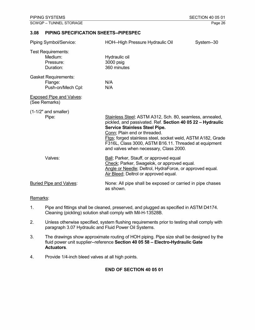
3.08 PIPING SPECIFICATION SHEETS--PIPESPEC
Piping Symbol/Service: HOH--High Pressure Hydraulic Oil System--30
Test Requirements: Medium: Hydraulic oil Pressure: 3000 psig Duration: 360 minutes
Gasket Requirements: Flange: N/A Push-on/Mech Cpl: N/A
Exposed Pipe and Valves: (See Remarks)
(1-1/2" and smaller) Pipe: Stainless Steel; ASTM A312, Sch. 80, seamless, annealed,
pickled, and passivated. Ref. Section 40 05 22 – Hydraulic Service Stainless Steel Pipe.
Conn; Plain end or threaded. Ftgs; forged stainless steel, socket weld, ASTM A182, Grade
F316L, Class 3000, ASTM B16.11. Threaded at equipment and valves when necessary, Class 2000.
Valves: Ball; Parker, Stauff, or approved equal Check; Parker, Swagelok, or approved equal. Angle or Needle; Deltrol, HydraForce, or approved equal. Air Bleed; Deltrol or approved equal.
Buried Pipe and Valves: None: All pipe shall be exposed or carried in pipe chases as shown.
Remarks:
1. Pipe and fittings shall be cleaned, preserved, and plugged as specified in ASTM D4174. Cleaning (pickling) solution shall comply with Mil-H-13528B.
2. Unless otherwise specified, system flushing requirements prior to testing shall comply with paragraph 3.07 Hydraulic and Fluid Power Oil Systems.
3. The drawings show approximate routing of HOH piping. Pipe size shall be designed by the fluid power unit supplier--reference Section 40 05 58 – Electro-Hydraulic Gate Actuators.
4. Provide 1/4-inch bleed valves at all high points.
END OF SECTION 40 05 01

PIPING CONNECTIONS SECTION 40 05 06.16
SCWQP – TUNNEL STORAGE Page 1
PART 1 - GENERAL
1.01 SECTION INCLUDES
A. This section specifies the following methods of connecting metallic piping: flanges, threading, mechanical couplings, equipment connection fittings, dielectric unions, and welding.
1.02 REFERENCE STANDARDS
A. REFERENCE STANDARDS: This Section incorporates by reference the latest revisions of the following documents. They are part of this Section insofar as specified and modified herein. In the event of conflict between the requirements of this section and those of the listed documents, the requirements of this Section shall prevail. Unless otherwise specified, references to documents shall mean the documents in effect on the effective date of the Agreement. If referenced documents have been discontinued by the issuing organization, references to those documents shall mean the replacement documents issued or otherwise identified by that organization or, if there are no replacement documents, the last version of the document before it was discontinued.
Reference Title
ANSI Bl.1 Unified Inch Screw Threads (UN and UNR Thread Form)
ANSI Bl.20.1 Pipe Threads, General Purpose (Inch)
ANSI B16.1 Cast Iron Pipe Flanges and Flanged Fittings
ANSI B16.5 Pipe Flanges and Flanged Fittings
ANSI B18.2.1 Square and Hex Bolts and Screws Inch Series
ANSI B18.2.2 Square and Hex Nuts (Inch Series)
ANSI B31.1 Power Piping
ANSI B31.3 Chemical Plant and Petroleum Refinery Piping
ASME Section IX Boiler and Pressure Vessel Code; Welding and Brazing Procedures, Welders, Brazers, and Welding and Brazing Operators Qualifications
ASTM B98 Copper-Silicon Alloy Rod, Bar and Shapes
ASTM F37 Standard Test Methods for Sealability of Gasket Materials
ASTM F104 Standard Classification System for Nonmetallic Gasket Materials
ASTM F152 Standard Test Methods for Tension Testing of Nonmetallic Gasket Materials
ASTM F593 Stainless Steel Bolts, Hex Cap Screws, and Studs
AWWA C111 Rubber-Gasket Joints for Ductile-Iron Pressure Pipe and Fittings
AWWA C206 Field Welding of Steel Water Pipe
AWWA C207 Steel Pipe Flanges for Waterworks Service-Size 4 in. through 144 in.
AWWA C219 Bolted, Sleeve-Type Couplings for Plain-End Pipe
AWWA C550 Protective Epoxy Coatings for Valves and Hydrants
AWWA C606 Grooved and Shouldered Joints
AWWA M11 Steel Pipe-A Guide for Design and Installation
NSF 61 Drinking Water System Components - Health Effects

PIPING CONNECTIONS SECTION 40 05 06.16
SCWQP – TUNNEL STORAGE Page 2
1.03 SUBMITTALS
A. PROCEDURES: Section 01 33 10 – Submittals.
B. SUBMITTAL ITEMS:
1. A copy of this specification section, with addendum updates included, and all referenced and applicable sections, with each paragraph check-marked to indicate compliance or marked to indicate requested deviations.
2. Manufacturer’s catalog data showing piping connection details for each piping system.
3. Details for installation for each type of piping connection.
4. A welder qualification certificate for each welder indicating the welder is certified for pipe welding in accordance with ASME Boiler and Pressure Vessel, Section IX.
5. For Equipment Connection Fittings used in pumping applications submit thrust rod stretch calculations in accordance with this Section and dimensional layout data.
PART 2 - PRODUCTS
2.01 GENERAL
A. Pipe connections (joint and fitting) options for a particular piping system shall be as specified on the particular system PIPESPEC sheet in Section 40 05 01 – Piping Systems.
B. TAKEDOWN COUPLINGS: To be provided for all piping systems in accordance with this Section. To be provided around equipment, at valves, and where otherwise specified.
C. Continuous welding for straight runs of pipe is acceptable only where the individual PIPESPEC sheet allows welding as a connection option.
D. Where connections are shown, the connections shall be specifically where shown. However, if several connection options are allowed for a particular piping system on the PIPESPEC sheet, then any option may be consistently used (i.e. if flanged or grooved connections are acceptable and grooved are shown, then flanged may be substituted). Integrity of rigid, non-rotating connections must be maintained at all valves and other equipment.
2.02 FLANGE ASSEMBLIES
A. Flanges:
1. General: Flanges shall either be flat flanges or convoluted ring flanges. Flange rating shall always exceed the test pressure requirement for the piping system as listed on the PIPESPEC sheet in Section 40 05 01 – Piping Systems.
2. Flat Flanges:

PIPING CONNECTIONS SECTION 40 05 06.16
SCWQP – TUNNEL STORAGE Page 3
a. Cast iron flanges shall be faced in accordance with ANSI B16.1. Where companion flanges are used, the flanges on pipe shall be refaced to be flush with the companion flange face.
b. Class 150 and Class 300 forged steel flanges shall be raised face conforming to ANSI B16.5.
c. Lightweight slip-on flanges shall be plain face conforming to AWWA C207, Class B and ANSI B16.5.
d. Unless otherwise specified, steel flanges shall be ANSI B16.5, Class 150 or AWWA C207, Class D. Class E AWWA flanges shall be provided where test pressure exceeds 175 psi. Plain faced flanges shall not be bolted to raised face flanges.
3. Convoluted Ring Flanges:
a. Convoluted ring flanges shall be ductile iron, forged steel or cast stainless steel, designed to bear on hubs welded to the pipe and shall be as manufactured by Improved Piping Products. The Engineer knows of no equal.
b. Flange joints shall be rated for not less than 150 percent of the test pressures listed in Section 40 05 01 – Piping Systems and shall conform to the requirements of ANSI B 16.5 and AWWA C207.
c. The flange manufacturer shall be prepared to demonstrate, by certified pressure test that the flanges will meet these requirements.
d. Acceptable manufacturers:
1) Improved Piping Products
2) Approved substitute
B. Gaskets:
1. Gasket material shall be as specified in this Section and Section 40 05 01 – Piping Systems.
2. Gaskets for plain faced flanges shall be the full face type. Thickness shall be 1/16 inch for pipe 10 inches and less in diameter and 1/8 inch for pipe 12 inches and larger in diameter.
3. Unless otherwise specified, gaskets for raised face flanges shall match the raised face and shall be 1/16 inch thick for pipe 3-1/2 inches and less in diameter and 1/8 inch thick for pipe 4 inches and larger.
C. Bolts:
1. Bolts and nuts shall be Type 316 stainless steel in accordance with ASTM F593 for bolts and ASTM F594 for nuts. Bolts shall be threaded to conform to ANSI B 18.2.1, page C-1 for finished hex bolts. Nuts shall conform to ANSI B 18.2.2, page D-1. Bolts and nuts shall be fully passivated. Nuts shall be finished with

PIPING CONNECTIONS SECTION 40 05 06.16
SCWQP – TUNNEL STORAGE Page 4
Tripac 2000 coating system, or approved substitute. All bolt heads and nuts shall be hexagonal. Identification of the head of the bolt shall be T-316, 316, F593G, or F593H.
2. Where washers are required, they shall be of the same material as the associated bolts.
2.03 MECHANICAL COUPLINGS
A. Sleeve-Type Couplings:
1. Acceptable manufacturers:
a. Sleeve-type mechanical pipe couplings:
1) Dresser Style 38
2) Smith-Blair Type 411
3) Approved substitute, with the stop removed from the middle ring
b. Reducing couplings:
1) Dresser Style 62
2) Smith-Blair Type 415
3) Approved substitute
c. Sleeve-type flanged coupling adapters:
1) Dresser Style 128.
2) Smith-Blair Type 913
3) Approved substitute
d. Insulating couplings:
1) Dresser Style 39
2) Smith-Blair Type 416
3) Approved substitute
2. Bolts and Nuts:
a. Bolts and nuts shall be Type 316 stainless steel in cormance with ASTM F593 for bolts and ASTM F594 for nuts. Bolts shall be threaded to conform to ANSI B 18.2.1, page C-1 for finished hex bolts. Nuts shall conform to ANSI B 18.2.2, page D-1. Bolts and nuts shall be fully passivated. Nuts shall be finished with Tripac 2000 coating system, or approved substitute. All bolt heads and nuts shall be hexagonal. Identification of the head of the bolt shall be T-316, 316, F593G, or F593H. Substitute Tripac 2000 Blue coated steel bolts and nuts where

PIPING CONNECTIONS SECTION 40 05 06.16
SCWQP – TUNNEL STORAGE Page 5
316 stainless components are not available as the manufacturer’s standard option.
b. Where washers are required, they shall be of the same material as the associated bolts.
3. Gaskets shall be as specified in this Section and AWWA C111.
B. Plain End Couplings:
1. Acceptable manufacturers:
a. Pipe sizes 6 inches and smaller (Schedule 80):
1) Anvil Gruvlock Figure 7005
2) Victaulic Style 99
3) Approved substitute
b. Pipe sizes 6 inches and smaller (lighter weight):
1) Anvil Gruvlock Figure 7005
2) Victaulic Style 90
3) Approved substitute
c. Pipe sizes 8 inches and larger:
1) Anvil Gruvlock Figure 7005
2) Victaulic Style 99
3) Approved substitute
2. Bolts and nuts:
a. Unless otherwise specified, bolts and nuts shall comply with AWWA C606.
b. Provide Type 316 stainless steel bolts and nuts. Bolts and nuts shall be fully passivated. Nuts shall be finished with Tripac 2000 coating system, or approved substitute. Substitute Tripac 2000 Blue coated standard steel bolts and nuts where 316 stainless components are not available as manufacturer’s standard option.
3. Gaskets shall be as specified in this Section and AWWA C606.
C. Grooved End Couplings:
1. Acceptable manufacturers:
a. Grooved end flexible-type couplings:
1) Anvil Gruvlok Figure 7001

PIPING CONNECTIONS SECTION 40 05 06.16
SCWQP – TUNNEL STORAGE Page 6
2) Victaulic Style 77/770
3) Approved substitute
b. Grooved end rigid-type couplings:
1) Anvil Gruvlok Figure 7401 Rigidlok (thru 24-inch)
2) Victaulic Style 07 Zero-Flex (thru 24-inch).
3) Approved substitute.
c. Grooved end flanged coupling adapters:
1) Anvil Gruvlok Figure 7012
2) Victaulic Style 741
3) Approved substitute
d. Snap-joint grooved end couplings:
1) Anvil Gruvlok Figure 7003
2) Victaulic Style 78
3) Approved substitute.
2. Unless specified otherwise, flexible-type couplings shall be used for all piping greater than 12 inches in diameter and for grooved joints adjacent to pump or blower suction and discharge where grooved couplings are used for noise and vibration control. All other applications for piping 12 inches in diameter and less shall utilize rigid-type couplings.
3. Cut grooves are not permitted on fabricated or light wall pipe with non-standard outside diameters or surface imperfections that may affect joint integrity. Minimum thickness shall be Schedule 40 through 6-inch and Schedule 30 for larger sizes.
4. Minimum thickness for roll grooved pipe shall be Schedule 5 or coupling manufacturer’s standard, whichever is greater.
5. Bolts and nuts:
a. Unless otherwise specified, bolts and nuts shall comply with AWWA C606.
b. Provide Type 316 stainless steel bolts and nuts. Bolts and nuts shall be fully passivated. Nuts shall be finished with Tripac 2000 coating system, or approved substitute. Substitute Tripac 2000 Blue coated standard steel bolts and nuts where 316 stainless components are not available as manufacturer’s standard option.
c. Where washer are required, they shall be of the same material as the associated bolts.

PIPING CONNECTIONS SECTION 40 05 06.16
SCWQP – TUNNEL STORAGE Page 7
6. Gaskets shall be as specified in this Section and AWWA C 606.
7. To assure uniformity and compatibility of piping components in grooved end piping systems, all grooved products utilized shall be supplied by the same manufacturer. Grooving tools shall be supplied by the same manufacturer as the grooved components. A factory trained representative (direct employee of grooved coupling manufacturer) shall provide on-site training and periodically visit the job site to review installation, as specified in Part 3.
D. Equipment Connection Fittings
1. Equipment connection fittings shall provide both lateral and angular misalignment adjustment between equipment connection flanges and the connection to field piping systems by providing individually adjustable flexible joints at each connection. In addition, equipment connection fittings shall provide full pressure thrust restraint between the field piping connection and equipment connection flanges.
a. Equipment connection fittings shall consist of two flanged coupling adapters, a plain end section of pipe and thrust restraint rods and associated fittings designed to transmit thrust without transmitting shear to the thrust restraint rods and without compromising provisions for accommodating angular and parallel misalignment.
b. Materials and features shall conform to the requirements established in this Section. Standard “dismantling joints” incorporate only one flanged coupling adapter and are not acceptable substitutes.
c. Acceptable manufacturers:
1) Baker Coupling Company, Los Angeles
2) Romac ECF Series
3) Approved equal, modified as specified to provide the required features
2. Equipment connection fittings shall each consist of a single sleeve of plain end piping conforming to the requirements of the specified piping system of sufficient length to span the gap between the connection at the equipment and the connection at the field piping with gasketed flange adapters at each end.
3. Thrust restraint shall be provided by means of all threaded rod spanning between flanges and male rod nuts and female washers that are rounded to provide a ball-joint type self-aligning feature. All threaded restraint rod shall project through flange and mating flange coupling adapter bolt holes or through holes in restraint lug plates that extend above the flanges and are secured to the flanges with a minimum of two flange bolts.
4. Where the all threaded rods project through flange bolt holes, ball joint type nut and washer combinations and lock washers shall be provided at each face, each end. Where restraint lug plates are employed, ball joint type nuts and washers shall be provided only on the outside faces of the plates and the nuts shall have

PIPING CONNECTIONS SECTION 40 05 06.16
SCWQP – TUNNEL STORAGE Page 8
a self-locking feature that prevents nut movement due to vibration or other operational or environmental causes.
5. Double nutting with non-locking nuts shall not be an acceptable method of providing the self-locking feature.
6. Thrust rod diameter and material shall be selected to provide sufficient freedom of movement through all bolt holes to allow unrestricted maximum adjustment of equipment connection fittings to accommodate piping misalignment without transmitting any shear to the thrust rods and also to permit full development of thrust restraint at all thrust rod tension take-ups.
7. Design of equipment connection fittings shall conform to AWWA C219.
8. Thrust rods, restraint lug plates, nuts, washers and lock washers shall be Type 316 stainless steel, all selected to develop full rated piping system pressure thrust forces. Bolts and nuts shall be fully passivated. Nuts shall be finished with Tripac 2000 coating system, or approved substitute. Equipment connection fittings for pump applications shall have thrust rod number and diameter selected such that thrust rod stretch under piping system operating pressure does not exceed 2 mils.
9. Dry film molybdenum di-sulfide anti-galling compound shall be factory applied to ends of thrust rods, covering all threads subject to nut travel and tightening.
10. Gaskets shall be as specified in this Section. Flange gaskets shall be full face type. Follower gaskets shall be compression wedge type.
11. Sleeves shall be carbon steel or as specified for the specific piping system. Pressure rating of flange adapters shall equal or exceed the pressure rating of mating flanges. All metal portions of equipment connection fittings, with the exception of 316 stainless steel components, shall be coated and lined with fusion bonded epoxy conforming to AWWA C550 and NSF 61.
E. Dismantling Joints:
1. Dismantling joints may be used as takedown couplings in accordance with this Section.
2. Dismantling joints shall fully restrained double flange fittings consisting of a flange coupling adapter and flanged spool piece that allows for longitudinal adjustment.
3. Thrust restraint shall be provided by means of all threaded rod spanning between flanges and secured to the flanges with a minimum of two flange bolts.
4. Design of equipment connection fittings shall conform to AWWA C219.
5. Sleeves shall be carbon steel or as specified for the specific piping system. Pressure rating of flange adapters shall equal or exceed the pressure rating of mating flanges.
PIPING CONNECTIONS SECTION 40 05 06.16
SCWQP – TUNNEL STORAGE Page 9
6. All metal portions of equipment connection fittings, with the exception of 316 stainless steel components, shall be coated and lined with fusion bonded epoxy conforming to AWWA C550 and NSF 61.
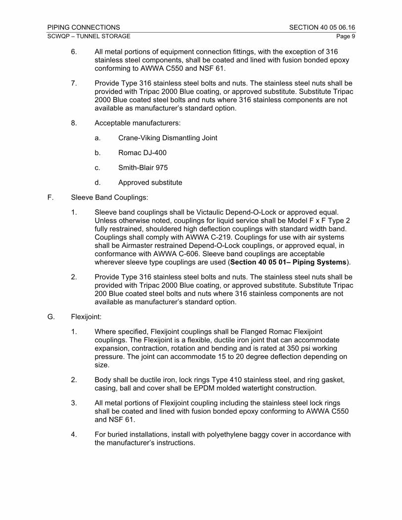
7. Provide Type 316 stainless steel bolts and nuts. The stainless steel nuts shall be provided with Tripac 2000 Blue coating, or approved substitute. Substitute Tripac 2000 Blue coated steel bolts and nuts where 316 stainless components are not available as manufacturer’s standard option.
8. Acceptable manufacturers:
a. Crane-Viking Dismantling Joint
b. Romac DJ-400
c. Smith-Blair 975
d. Approved substitute
F. Sleeve Band Couplings:
1. Sleeve band couplings shall be Victaulic Depend-O-Lock or approved equal. Unless otherwise noted, couplings for liquid service shall be Model F x F Type 2 fully restrained, shouldered high deflection couplings with standard width band. Couplings shall comply with AWWA C-219. Couplings for use with air systems shall be Airmaster restrained Depend-O-Lock couplings, or approved equal, in conformance with AWWA C-606. Sleeve band couplings are acceptable wherever sleeve type couplings are used (Section 40 05 01– Piping Systems).
2. Provide Type 316 stainless steel bolts and nuts. The stainless steel nuts shall be provided with Tripac 2000 Blue coating, or approved substitute. Substitute Tripac 200 Blue coated steel bolts and nuts where 316 stainless components are not available as manufacturer’s standard option.
G. Flexijoint:
1. Where specified, Flexijoint couplings shall be Flanged Romac Flexijoint couplings. The Flexijoint is a flexible, ductile iron joint that can accommodate expansion, contraction, rotation and bending and is rated at 350 psi working pressure. The joint can accommodate 15 to 20 degree deflection depending on size.
2. Body shall be ductile iron, lock rings Type 410 stainless steel, and ring gasket, casing, ball and cover shall be EPDM molded watertight construction.
3. All metal portions of Flexijoint coupling including the stainless steel lock rings shall be coated and lined with fusion bonded epoxy conforming to AWWA C550 and NSF 61.
4. For buried installations, install with polyethylene baggy cover in accordance with the manufacturer’s instructions.

PIPING CONNECTIONS SECTION 40 05 06.16
SCWQP – TUNNEL STORAGE Page 10
2.04 GASKETS
A. Gaskets designated in Section 40 05 01 – Piping Systems shall be as follows:
1. EPDM: ethylene-propylene-diene-terpolymer
2. Neoprene: neoprene
3. Nitrile: nitrile (Buna N)
4. Viton
5. Compressed gasketing consisting of organic fibers (Kevlar) and neoprene binder:
a. Classification: ASTM F104 (F712400)
b. Tensile Strength: 2500 psi (ASTM F152)
c. Leakage: 0.2 ML/HR LEAKAGE FUEL A (ASTM F37)
6. Compressed gasketing consisting of organic fibers (Kevlar) and nitrile binder:
a. Classification: ASTM F104 (F712400)
b. Tensile Strength: 2500 PSI (ASTM F152)
c. Leakage: 0.1 ml/hr leakage Fuel A (ASTM F37).
7. Gylon gasketing, Garlock Style 3500:
a. Tensile Strength: 2000 psi (ASTM F152)
b. Leakage: 0.22 ml/hr Fuel A (ASTM F37)
8. Gylon gasketing, Garlock Style 3504:
a. Tensile Strength: 2000 psi (ASTM F152)
b. Leakage: 0.12 ml/hr Fuel A (ASTM F37)
9. Gylon gasketing, Garlock Style 3510:
a. Tensile Strength: 2000 psi (ASTM F152)
b. Leakage: 0.04 ml/hr Fuel A (ASTM F37)
10. TFE: noncreeping tetrafluoroethylene (TFE) with insert filler.
11. PTFE bonded EPDM: PTFE bonded to EPDM in full-face gasket having concentric-convex molded rings.
2.05 THREAD
A. Pipe thread dimensions and size limits shall conform to ANSI Bl.20.1.

PIPING CONNECTIONS SECTION 40 05 06.16
SCWQP – TUNNEL STORAGE Page 11
2.06 UNIONS
A. Unions 2 inches and smaller shall be ground joint screwed pattern unions. Unions 2-1/2 inches and larger shall be ground joint flange unions.
B. DIELECTRIC UNIONS: Match the pipe material expect bronze may be used with copper piping. Dielectric unions shall be EPCO, Capitol Manufacturing, or approved substitute.
C. Hydraulic power and petroleum conveying piping shall use flat-faced O-ring systel unions for both regular and dielectric unions. O-ring material shall be suitable for piped fluid.
2.07 COATINGS
A. Unless otherwise specified, flange assemblies and mechanical type couplings for buried installation shall be field coated with System M-1 as specified in Section 09 90 00 - Coatings.
PART 3 - EXECUTION
3.01 PIPE CUTTING, THREADING AND JOINTING
A. Pipe cutting, threading and jointing shall conform to the requirements of ANSI B31.1.
3.02 PIPE WELDING
A. Pipe shall be welded by ASME-certified welders using shielded metal arc, gas shielded arc or submerged arc welding methods. Provide welding certification for each welder working on pipe fabrication.
B. Welds shall be made in accordance with the requirements of ANSI B31.1 for piping Systems 8, 26, and 28 specified in Section 40 05 01 – Piping Systems. Welds shall be made in accordance with the requirements of ANSI B31.3 for piping System 20 specified in Section 40 05 01 – Piping Systems.
C. Welds for piping systems not specified above shall be made in accordance with AWWA C206.
3.03 GROOVED END COUPLINGS
A. A factory trained representative (direct employee of a grooved coupling manufacturer) shall provide on-site training for Contractor’s field personnel in the use of grooving tools, application of groove, and product installation. A factory-trained representative shall periodically visit the job site and review installation. Contractor shall promptly remove and replace any improperly installed products or piping distorted or damaged by incorrect preparation.
3.04 TAKEDOWN COUPLINGS
A. Takedown couplings shall be screw unions, flanged or grooved end mechanical coupling type joints and shall be provided as specified.

PIPING CONNECTIONS SECTION 40 05 06.16
SCWQP – TUNNEL STORAGE Page 12
B. Flanged or grooved end joints shall be employed on pipelines 2-1/2 inches in diameter and larger.
C. Where piping passes through walls, takedown couplings shall be provided within 3 feet of the wall, unless specified otherwise.
D. A union or flanged connection shall be provided within 2 feet of each threaded end valve.
3.05 FLEXIBILITY
A. Unless otherwise specified, piping passing from concrete to earth shall be provided with two pipe couplings or flexible joints (or a single Flexijoint) as specified on the buried pipe within 2 feet of the structure for 2-inch through 6-inch diameter pipe; within 3 feet of the structure for 8-inch through 24-inch diameter pipe; and within one and one-half pipe diameters of the structure for larger pipe. Where required for resistance to pressure, mechanical couplings shall be restrained in accordance with Chapter 13 of AWWA M11, including Tables 13-4, 13-5 and 13-5A, and Figure 13-20.
B. Restrain all flexible joints for pressurized ductile iron joints. Lugs for restraint on ductile iron pipe shall be factory installed.
3.06 DIELECTRIC CONNECTIONS
A. Provide an insulating section of rubber or plastic pipe where a copper pipe is connected to steel or cast iron pipe. The insulating section shall have a minimum length of 12 pipe diameters.
B. Dielectric unions as specified in this Section may be used instead of the specified insulating sections. Where copper pipe is supported from hangers, it shall be insulated from the hangers, or copper-plated hangers shall be used.
3.07 EQUIPMENT CONNECTION FITTINGS
A. Where shown, equipment connection fittings shall be provided between field piping systems and equipment inlet and outlet connections.
END OF SECTION 40 05 06.16
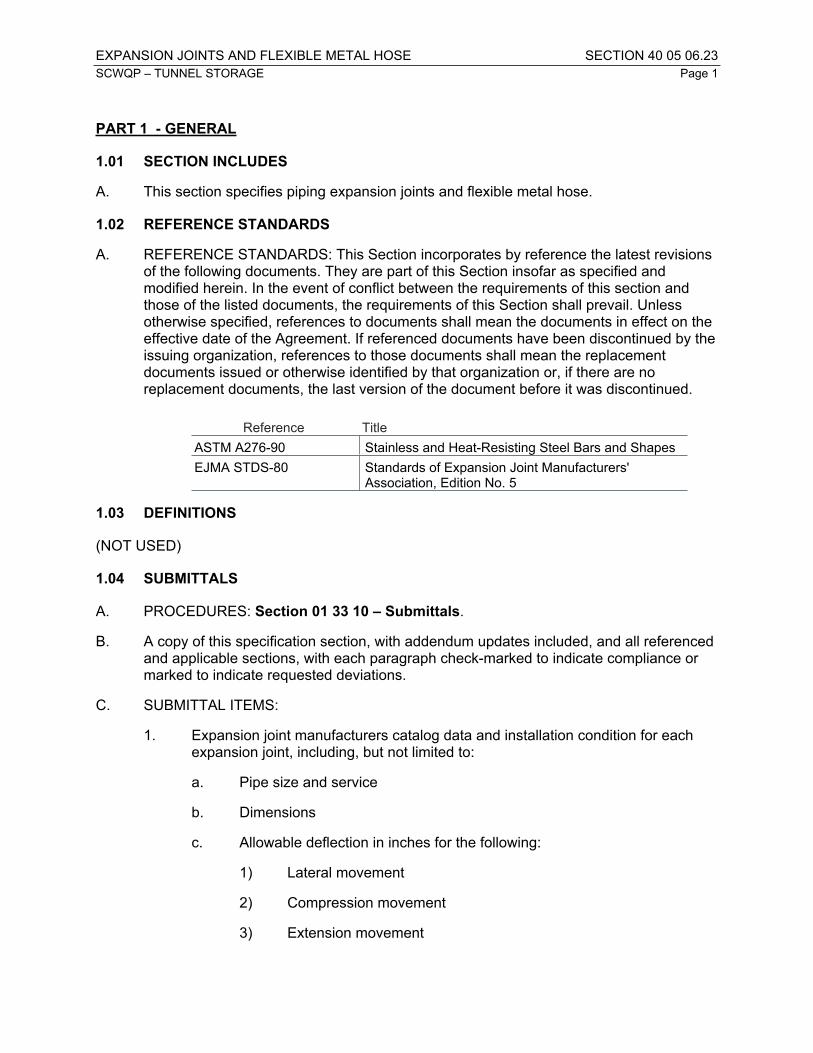
EXPANSION JOINTS AND FLEXIBLE METAL HOSE SECTION 40 05 06.23SCWQP – TUNNEL STORAGE Page 1
PART 1 - GENERAL
1.01 SECTION INCLUDES
A. This section specifies piping expansion joints and flexible metal hose.
1.02 REFERENCE STANDARDS
A. REFERENCE STANDARDS: This Section incorporates by reference the latest revisions of the following documents. They are part of this Section insofar as specified and modified herein. In the event of conflict between the requirements of this section and those of the listed documents, the requirements of this Section shall prevail. Unless otherwise specified, references to documents shall mean the documents in effect on the effective date of the Agreement. If referenced documents have been discontinued by the issuing organization, references to those documents shall mean the replacement documents issued or otherwise identified by that organization or, if there are no replacement documents, the last version of the document before it was discontinued.
Reference TitleASTM A276-90 Stainless and Heat-Resisting Steel Bars and ShapesEJMA STDS-80 Standards of Expansion Joint Manufacturers'
Association, Edition No. 5
1.03 DEFINITIONS
(NOT USED)
1.04 SUBMITTALS
A. PROCEDURES: Section 01 33 10 – Submittals.
B. A copy of this specification section, with addendum updates included, and all referenced and applicable sections, with each paragraph check-marked to indicate compliance or marked to indicate requested deviations.
C. SUBMITTAL ITEMS:
1. Expansion joint manufacturers catalog data and installation condition for each expansion joint, including, but not limited to:
a. Pipe size and service
b. Dimensions
c. Allowable deflection in inches for the following:
1) Lateral movement
2) Compression movement
3) Extension movement

EXPANSION JOINTS AND FLEXIBLE METAL HOSE SECTION 40 05 06.23SCWQP – TUNNEL STORAGE Page 2
4) Angular movement
d. Test pressure, psig
e. Pressure force, pounds
f. Pressure area and total forces
g. Expansion joint description
h. Materials
i. Special features
2. Details for installation of all expansion joints
1.05 PERFORMANCE REQUIREMENTS
A. Performance and Service Conditions:
1. Expansion joints shall be designed in accordance with EJMA Standards for pressure, temperature and service as specified.
2. Flexible metal hose shall be suitable for a line pressure equal to the test pressure listed in the PIPESPEC sheets in Section 40 05 01 – Piping Systems.
B. Design Requirements:
1. Flexible Metal Hose: Live lengths for flexible metal hose shall be based upon the service conditions listed in this Section and a design life of 1,000,000 full displacement cycles.
2. Expansion Joints: Corrugated type expansion joints shall be suitable for a minimum of 10,000 pressure, temperature and deflection cycles (non-concurrent).
PART 2 - PRODUCTS
2.01 EXPANSION JOINTS
A. Metal Construction:
1. General:a. All welding shall be in accordance with ASME Section IX.b. Expansion joints weighing more than 500 pounds shall be provided with
lifting lugs.c. Expansion joints shall be provided with stainless steel nameplates
indicating date of manufacture, design pressure and temperature rating of the expansion joint, design movements, and required life cycle.
2. Universal Tied Expansion Joint:

EXPANSION JOINTS AND FLEXIBLE METAL HOSE SECTION 40 05 06.23SCWQP – TUNNEL STORAGE Page 3
a. Universal tied expansion joints shall have 300 series stainless steel mutli-ply bellows rated for the specified design temperature and pressure.
b. Test pressure shall be as specified in Section 40 05 01 – Piping Systems.
c. Design shall be determined by the amount and kind of movement specified.
d. Acceptable manufacturers:1) Flexonics2) Hyspan Series 15003) U.S. Bellows4) Approved equal
3. Steel Expansion Compensator Type:a. Compensators shall have 2-ply stainless steel bellows and carbon steel
shroud and end fittings.b. Compensators shall be rated for 175 psi maximum working pressure and
750 degrees F.c. Acceptable manufacturers:
1) Flexonics Model H Expansion Compensator2) Hyspan Series 85003) Keflex 7Q4) Approved equal
4. Bronze Expansion Compensator Type:a. Compensators shall be multi-ply phosphor bronze or stainless steel
bellows and copper tube end fittings.b. Compensators shall be rated for 150 psi maximum work pressure and
400 degrees F.c. Acceptable manufacturers:
1) American BOA2) Flexonics Model HB Expansion Compensator3) Hyspan Series 85004) Keflex 7Q5) Approved equal
B. Elastomer and Fabric Construction:
1. General:a. Elastomer and fabric expansion joints shall be the standard spool arch
type or the precision molded spherical design type as specified.

EXPANSION JOINTS AND FLEXIBLE METAL HOSE SECTION 40 05 06.23SCWQP – TUNNEL STORAGE Page 4
b. Expansion joint connectors shall have control units (restraints) to prevent excessive axial elongation and to accept the static pressure thrust in the piping system. Number and sizes of control rods or restraints shall be as determined by the manufacturer.
c. Unless otherwise specified, single arch and sphere type expansion joints shall have 6-inch face-to-face dimension for pipe up to 8 inches and 8-inch face-to-face dimension for pipe 10 and 12 inches. For use with larger diameters, Contractor shall obtain approval from SPU.
d. The cover elastomer shall be neoprene or Buna N.
2. Spool Typea. Spool type expansion joints shall be of the resilient arch type and shall be
standard or tapered as specified. Unless otherwise specified, all tapered connectors shall be eccentric.
b. Spool type expansion joints shall be constructed of multiple plies of woven fabric impregnated with elastomer and reinforced with steel rings or wire embedded in the body.
c. Standard arch type expansion joints suitable for the specified temperature and pressure shall be provided with retaining rings or backup rings. Retaining rings shall be 3/8-inch thick steel, split, either galvanized or zinc shield coated.
d. Filled arch type shall be used on all piping systems carrying fluids containing solids.
e. Acceptable manufacturers:1) Single, multiple, or filled arch:
a) Garlock Style 204b) General Style 1025c) Goodall Style E-1462d) Mason Style EJBNe) Mercer Style 500f) Approved equal.
3. Spherical Molded Type:a. Spherical molded type expansion joints shall be precision molded of
multiple plys of nylon tire cord fabric and elastomer suitable for specified temperature and pressure.
b. Spherical molded type expansion joints shall have steel or ductile iron floating flanges, and no metal parts shall come in contact with the fluid.
c. Acceptable manufacturers (single sphere molded connectors):1) Garlock Style 81002) General Type 10103) Goodall Type E-611

EXPANSION JOINTS AND FLEXIBLE METAL HOSE SECTION 40 05 06.23SCWQP – TUNNEL STORAGE Page 5
4) Mason Type MFNC5) Mercer Type 55006) Approved equal
d. Double sphere or triple sphere connectors shall be provided where required to provide for the specified movement.
C. OTHER CONSTRUCTIONS:
1. Polyvinylchloride:a. Acceptable manufacturers:
1) Celanese “Chemtrol” CPVC slip type having Teflon impregnated seal rings.
2) Certain-teed Fluid Tite PVC3) Johns-Manville PVC double bell expansion joint4) Approved equal
2. Teflon:a. Consist of molded PTFE bellows and 150-pound ductile iron flanges.b. Flanges shall be completed isolated from the chemical by the molded
PTFE bellows.c. Integral steel limit bolts and Monel reinforcing rings shall be provided on
the connectorsd. Gaskets shall be PTFE.e. The connector shall allow for an axial transverse movement of at least
1/2-inch and an offset of at least 3/8-inch.f. Rated for a pressure of 130 psi at a temperature of 70 degrees F.g. Acceptable manufacturers:
1) EGC Style M-1502) Garlock Style 2153) Metraflex T-24) Reistoflex R-69055) Approved equal
2.02 FLEXIBLE METAL HOSE
A. General:
1. Flexible metal hose shall be corrugated type 321 stainless steel with stainless steel fittings and shall be provided with stainless steel single braid, unless otherwise specified.
2. End connections shall be attached by the heliarc welding process using stainless steel welding rod.

EXPANSION JOINTS AND FLEXIBLE METAL HOSE SECTION 40 05 06.23SCWQP – TUNNEL STORAGE Page 6
3. Bronze flexible metal hose shall be provided for copper and brass systems.
B. Braided Type:
1. Type A:a. Acceptable manufacturers:
1) American BOA Series B2) Flexonics Series 401M/402M3) Flexweld USFWSS-31/324) Approved equal.
2. Type B:a. Acceptable manufacturers:
1) American BOA Series B2) Flexonics Series 3013) Flexweld USFWB-314) Approved equal
2.03 FLEXIBLE TEFLON HOSE
A. General:
1. Provide Teflon tube, supported by double steel wire helix. Provide abrasion and weather-resistant protective rubber cover.
2. End connections shall be Teflon encapsulated 150-pound flange connections.
B. Acceptable manufacturers:
1. Jack-Chem
2. Approved equal
PART 3 - EXECUTION
3.01 INSTALLATION
A. Expansion joints and anchors shall be located as specified in Section 40 05 01 – Piping Systems and Section 40 05 07.16 – Expansion Control for Piping.
B. Do not install expansion joints during times of extreme temperature or in a fully compressed or fully expanded condition.
C. Expansion joints shall be properly anchored and guided. Whenever possible, install the expansion joint at locations specified on the Drawings. Locate the anchor or first pipe alignment guide no more than 4 pipe diameters from the expansion joint. The second guide should be located no more than 14 pipe diameters from the first guide. Additional pipe guides should be installed in accordance with the manufacturer's recommendations.

EXPANSION JOINTS AND FLEXIBLE METAL HOSE SECTION 40 05 06.23SCWQP – TUNNEL STORAGE Page 7
3.02 ALIGNMENT
A. Piping systems shall be aligned prior to installation of expansion joints.
B. Expansion joints shall not be used to correct piping misalignment during installations.
C. Expansion joints normally preset at the factory for rated axial compression and expansion shall be installed in this preset condition.
3.03 EXPANSION JOINT AND CONNECTOR SCHEDULE
A. Expansion joints and/or flexible metal hose connectors shall generally be provided for specific equipment items or piping systems as specified on the following schedule. The specific location and number of piping system expansion joints shall be determined by the Contractor’s Design Professional as specified in Section 40 05 01 – Piping Systems.
B. If a particular joint or connector is shown or specified for a given location, that more detailed selection shall apply.
Expansion Joint and Connector ScheduleType of Expansion Joint/Connection Type of Service/UseSteel expansion compensator (2.01 A.3) High pressure air and steel lines.Bronze expansion compensator (2.01 A.4) Copper piping.Elastomer spool arch, restrained (2.01 B.2) Blower connectors 14 inch diameter and
larger.PVC (2.01 C.1) PVC pipingTeflon (2.01 C.2) RTRPEquipment connection fitting, restrained
(Section 40 05 06.16 – Piping Connections)
Pumps, 3-inch diameter or greater, both suction and discharge, and other equipment where shown.
END OF SECTION 40 05 06.23

PIPING APPURTENANCES SECTION 40 05 06.33
SCWQP – TUNNEL STORAGE Page 1
PART 1 - GENERAL
1.01 SECTION INCLUDES
A. Scope:
1. This section specifies general connection information for pipeline instrumentation, strainers, sight glasses, vents, drains, and other devices specified herein and elsewhere
B. Exclusions:
1. Temperature, pressure and flow measuring devices used for instrumentation are specified in Division 40. Instruments are identified in the instrument index in Section 40 70 00 – Instrumentation for Process Systems.
1.02 REFERENCE STANDRDS
(NOT USED)
1.03 DEFINITIONS
(NOT USED)
1.04 SUBMITTALS
A. PROCEDURES: Section 01 33 10 – Submittals.
B. A copy of this specification section, with addendum updates included, and all referenced and applicable sections, with each paragraph check-marked to indicate compliance or marked to indicate requested deviations.
C. SUBMITTAL ITEMS:
1. Appurtenances shall be located on the piping layout Drawings and submitted in accordance with Section 40 05 01 – Piping Systems.
2. Manufacturer’s product data, measurement ranges, materials of construction, dimensions, typical installation and application information.
PART 2 - PRODUCTS
2.01 GENERAL
A. Unless otherwise specified:
1. Body material of equipment shall match pipeline material.
2. Pressure rating of equipment shall be no less than 150 psi.
B. All units shall have the name of the manufacturer and the size of the unit cast on the body or shown a permanently attached plate in raised letters.

PIPING APPURTENANCES SECTION 40 05 06.33
SCWQP – TUNNEL STORAGE Page 2
C. All equipment provided shall be equipped with flanges, integral unions, or other functional take-aparts.
2.02 PIPELINE CONNECTIONS:
A. GENERAL:
1. Pipeline connections for instrumentation, not otherwise specified, shall be fabricated with a 3-inch FNPT branch outlet on the process pipe, a 3-inch male NPT by 3/4-inch female NPT reducing bushing, a 3/4-inch by 3-inch long threaded nipple, and a threaded ball valve with lock open provisions.
2. Materials and methods of connections, not otherwise specified, shall be the same as the process piping system per Section 40 05 01 – Piping Systems.
B. CONNECTION TYPES:
1. Connection types and details are specified with the instrumentation in Section 40 70 00 – Instrumentation for Process Systems.
2. Connection types shall protect the integrity of the process pipe and the lining and shall be, as a minimum:
a. Glass-lined ductile iron and steel pipe: factory installed threaded half-coupling, installed prior to lining, or tee with tapped blind flange or tap.
b. Unlined steel and stainless steel pipe: reducing tee or threaded half coupling.
c. HDPE pipe: reducing tee or electro-fusion welded saddle by butt end.
d. PVC/CPVC pipe – solvent welded tee with branch socket adapted with solvent welded pipe or Schedule 80 threaded fitting to suit use. Transition to metal pipe or fittings shall be PVC male NPT to threaded metal or flange by flange.
2.03 FLOW AND LEVEL GAGES
A. Sight Gages:
1. Sight gages shall be 3/4-inch Penberthy 205 Series, Lunkenheimer Fig. 589, or approved equal, automatic water gage complete with pyrex gage glass and gage glass protector. Overall length of gages, type of mounting, and orientation of set shall be as specified.
B. Flow Indicators:
1. Flow indicators shall be provided where specified. Each indicator shall consist of a bronze body with threaded ends and a sight glass with rotary wheel. Pressure ratings for flow indicators shall match pipe pressure ratings. Indicators shall be as manufactured by Jacoby-Tarbox, Schutte & Koerting, Eugene Ernst Products, or approved equal.

PIPING APPURTENANCES SECTION 40 05 06.33
SCWQP – TUNNEL STORAGE Page 3
2.04 PRESSURE DEVICES
A. Gage Cocks:
1. Unless otherwise specified, gage cocks shall be Robertshaw 1303, Ashcroft 1095, or approved equal. The exposed threads of each gage cock shall be protected by a brass plug.
B. Pressure Gages:
1. Unless otherwise specified, pressure gage scales shall be selected so that the normal operating pressure falls between 50 and 80 percent of full scale, shall be 4 1/2-inch, 270-degree movement, 1/2-percent accuracy, full-scale, and suitable for bottom stem mounting. Gages shall have a 316-SS bourdon tube. All gages shall have a 300 series stainless steel case, shatterproof glass, and a 1/2-inch NPT bottom connection.
2. Pressure gages for air, gas, and low pressure services (0-10 feet) shall be premium grade, heavy-duty bourdon-tube units (bellow type for vacuum) with Delrin bushings and pinion, and stainless steel sector.
3. Gages on liquid service shall be as noted above, except they shall be provided with an internal pulsation dampening system consisting of either a glycerin fill or a silicone fluid fill. Snubbers or orifices shall not be utilized. Gages shall be Ashcroft Duragauge Fig. 1279, Ametek 1981L, or approved equal.
C. Diaphragm Seals:
1. Unless otherwise specified, seals shall be diaphragm type with 1/4-inch flushing connection, Type 316 stainless steel body and Type 316L diaphragm. Fill fluid shall be Silicone DC200 unless otherwise specified. Seal shall be Mansfield and Green Type SG, Ashcroft Type 101, or approved equal.
D. Pressure Sensors
1. Unless otherwise specified, pressure sensors (tubular chemical seals) shall be the in-line full stream captive sensing liquid type. Wetted parts shall be 316 stainless steel. Flexible cylinder shall be Buna-N unless otherwise specified. Seals shall be rated for 200 psi with 5-inch SC hysteresis. Seals shall be Ronningen-Petter, Red Valve, or approved equal.
2. Fill fluid shall be rated for a temperature range of -20 degrees F to 200 degrees F. Capillary tubing shall be armored stainless steel. Fittings shall be provided for vacuum filling of system. Systems that are not factory filled shall be vacuum filled in the field. Filling connections shall be soldered shut after vacuum evacuation and filling.
2.05 STRAINERS
A. Air and Gas Strainers:
1. Unless otherwise specified, air and gas line strainers shall be Y-pattern, cast iron body, with 40 mesh Monel screens packed with Everdur wool. Bronze bodies

PIPING APPURTENANCES SECTION 40 05 06.33
SCWQP – TUNNEL STORAGE Page 4
shall be provided with copper piping. Air line strainers shall be fitted with a brass blowoff cock. Strainers shall be Mueller, Armstrong, or approved equal.
B. Water Strainers:
1. Steam and water strainers shall be of Y-pattern, unless otherwise specified. Steam strainers shall have carbon steel body; water strainers shall have cast iron body. Bronze bodies shall be provided with copper piping. Strainers shall have 304 stainless steel screens and tapped and plugged blowoff connections. Screen perforations shall be 0.020 inch for steam service and 0.045 inch for water service. Strainers shall be Mueller, Armstrong, or approved equal.
C. Fuel Oil Strainers:
1. Fuel oil strainers shall be of the basket type and shall have cast iron body with 304 stainless steel screens. Screen perforation shall be 3/64 inch. Strainers shall be Bailey No. 1, Mueller, or approved equal.
PART 3 - EXECUTION
3.01 INSTALLATION
A. Install piping appurtenances in accordance with submitted layout drawings, applicable details and manufacturer’s written recommendations.
B. Repair linings damaged during installation. Damaged glass-lined pipe and/or fittings shall be replaced.
C. Appurtenances shall be installed in such a manner as to free of pipe strain in either the installed or operating conditions. Adjust pipe support systems, as required.
3.02 GAGE TAPS
A. Gage taps shall be provided on the suction and discharge of pumps, fans, compressors, vacuum pumps and blowers. Gage taps shall consist of a 1/4-inch gage cock attached by a threaded nipple to the pipeline, duct or equipment.
3.03 VENTS AND DRAINS
A. Manual air vents shall be provided at the high points of each reach of pipeline where specified. Air vents shall consist of bronze cock and copper tubing return. Air vents shall be taken to the nearest floor with cock mounted 4 feet above the floor. Vents in piping systems for fluids containing solids shall be 1-inch nonlubricated eccentric plug valves fitted with quick couplers.
B. Drains shall be piped to a sump, gutter, floor drain or other collection point with a valve mounted 4 feet above the floor. Drain valves shall be threaded end gate valves of the size specified. When drains cannot be run to collection points, they shall be routed to a point of easy access and shall have hose gate valves of the size specified.

PIPING APPURTENANCES SECTION 40 05 06.33
SCWQP – TUNNEL STORAGE Page 5
3.04 COMPONENT TEST PHASE
A. Demonstrate successful performance of devices in conjunction with connected piping system, pump, or other equipment.
END OF SECTION 40 05 06.33

HANGERS AND SUPPORTS FOR PROCESS PIPING SECTION 40 05 07SCWQP – TUNNEL STORAGE Page 1
PART 1 - GENERAL
1.01 SECTION INCLUDES
A. Scope:
1. This Section specifies requirements for design, selection, and installation of hangers and support for piping specified in Section 40 05 01 – Piping Systems.
2. This Section does not specify design and installation requirements for pipe hanger and supports for piping systems that are not specified in Section 40 05 01 – Piping Systems.
3. Requirements for pipe expansion control are specified in Section 40 05 07.16 – Expansion Control for Piping. Requirements for design of seismic restraints for piping and foul air ducts are specified in Section 40 05 07.13 – Seismic Restraints for Piping and Section 01 73 24 – Design Requirements for Non-Structural Components and Non-Building Structures.
4. This Section specified inspection requirements for piping, pipe hangers, FA ducts, supports, restraints, and expansion control construction.
1.02 REFERENCE STANDARDS
A. REFERENCE STANDARDS: This Section incorporates by reference the latest revisions of the following documents. They are part of this Section insofar as specified and modified herein. In the event of conflict between the requirements of this section and those of the listed documents, the requirements of this Section shall prevail. Unless otherwise specified, references to documents shall mean the documents in effect on the effective date of the Agreement. If referenced documents have been discontinued by the issuing organization, references to those documents shall mean the replacement documents issued or otherwise identified by that organization or, if there are no replacement documents, the last version of the document before it was discontinued.
Reference TitleAISC Manual of Steel Construction American Institute of Steel Construction, Manual of
Steel Construction, Allowable Stress Design - 9th Ed.
FEDSPEC WW-H-171e-78 Hangers and Supports, Pipe MFMA-2-91 Metal Framing Standards PublicationMSS SP-69-91 Pipe Hangers and Supports - Selection and
Application MSS SP-58-93 Pipe Hangers and Supports - Materials, Design
and Manufacture
1.03 DEFINTIONS
(NOT USED)

HANGERS AND SUPPORTS FOR PROCESS PIPING SECTION 40 05 07SCWQP – TUNNEL STORAGE Page 2
1.04 SUBMITTALS
A. PROCEDURES: Section 01 33 10 – Submittals.
B. A copy of this specification section, with addendum updates included, and all referenced and applicable sections, with each paragraph check-marked to indicate compliance or marked to indicate requested deviations.
C. SUBMITTAL ITEMS:
1. Hanger and support locations and components shall be shown on the piping layout drawings as required by Section 40 05 01 – Piping Systems and Section 01 73 24 – Design Requirements for Non-Structural Components and Non-Building Structures.
2. Fabrication drawings for fabricated components.
3. Manufacturer’s catalog data on pipe supports and components, including weight limits, permissible moment arms, and other data.
4. Submit stamped drawings and design calculations for all support in Accordance with Section 01 73 24 – Design Requirements for Non-Structural Components and Non-Building Structures.
5. A final inspection report, authored, sealed, and signed by the Design Professional. The Design Professional’s final report shall be submitted to SPU before beneficial occupancy by SPU. Special Inspections will be performed by SPU in accordance with Section 01 73 24 – Design Requirements for Non-Structural Components and Non-Building Structures.
1.05 SERVICE REQUIREMENTS
A. Expansion control provisions are required to accommodate expansion and/or contraction of pipe materials as a result of varying ambient temperature conditions. The Contractor’s pipe hanger design and support selection shall accommodate expansion/contraction without interfering with expansion control functions.
B. All piping services are assumed to have operating temperature conditions within the range of ambient temperature conditions. For the purposes of design and/or installing pipe hangers, supports, seismic, bracing, and expansion control components of piping systems, ambient temperature conditions are defined as 20 to 100 degrees F.
C. Until commissioning is complete, the Contractor is responsible for protecting piping systems against damage resulting from expansion or contraction of pipe materials exposed to temperatures outside the ambient temperature condition range.
1.06 HANGER AND SUPPORT DESIGN AND SELECTION
A. Design:
1. Within the scope defined in Section 40 05 07 – Hangers and Supports for Process Piping, the Contractor’s Design Professional, specified in Section 40 05 01 – Piping Systems, shall be responsible for design of hanger and support

HANGERS AND SUPPORTS FOR PROCESS PIPING SECTION 40 05 07SCWQP – TUNNEL STORAGE Page 3
systems, seismic restraints, and expansion control systems. Applicable design criteria include, but are not limited to, those design standards specified in Section 40 05 01 – Piping Systems and Section 01 73 24 – Design Requirements for Non-Structural Components and Non-Building Structures.
2. Steel support and bracing elements shall be sized and selected using allowable stress design basis.
3. As the elements must work together, the pipe system drawings specified in Section 40 05 01 – Piping Systems shall show the hanger and support locations as well as the details of the seismic restraints and expansion control systems, regardless of design responsibility. The pipe design Drawings and calculations shall be prepared and signed by the Design Professional and shall bear the design professional’s registration seal in the State of Washington.
4. Where a specific support, hanger, guide, structural attachment, anchor, joint, seismic restraint, or expansion control detail is shown on the Drawings, it shall be to indicate the required configuration or general arrangement to be developed by the Contractor’s Design Professional. The Drawings are not a complete pipe support design and do not relieve the Contractor from the requirements of this Section.
5. Design, select, locate, and provide piping supports, pipe guides, and seismic restraint required for final piping layout.
B. The Contractor shall select pipe hangers and supports as specified within this Section. Selections shall be based upon the Design Professional’s design, the Drawings, and piping insulation thickness specified in Section 40 42 00 – Insulation for Exposed Piping and Equipment.
C. The Contractor shall review the piping layout in relation to the surrounding structure and adjacent piping and equipment before selecting the type of support to be used at each hanger point.
D. Hangers and supports shall withstand all static and specified dynamic conditions of loading to which the piping and associated equipment may be subjected. As a minimum, consideration shall be given to the following conditions:
1. Weights of pipe, valves, fittings, insulating materials, suspended hanger components, and normal fluid contents.
2. Weight of hydrostatic test fluid or cleaning fluid if normal operating fluid contents are lighter.
3. Reaction forces due to the operation of safety or relief valves.
4. Supports shall be designed to prevent transfer of pipe support loads to pipe connections on equipment.
E. Hangers and supports shall be sized to fit the outside diameter of pipe, tubing, and the outside diameter of insulation where piping is insulated.

HANGERS AND SUPPORTS FOR PROCESS PIPING SECTION 40 05 07SCWQP – TUNNEL STORAGE Page 4
F. Where negligible movement occurs at hanger locations, rod hangers shall be used for suspended lines, wherever practical. For piping supported from below, bases, brackets or structural cross members shall be used.
G. Hangers for the suspension of size 2-1/2 inches and larger pipe and tubing shall be capable of vertical hanger component adjustment under load.
H. The supporting systems shall provide for the free or intended movement of the piping including its movement in relation to that of connected equipment.
I. Where there is horizontal movement at a suspended type hanger location, hanger components shall be selected to allow for swing. The vertical angle of the hanger rod shall not, at any time, exceed 4 degrees.
J. There shall be no contact between a pipe and hanger or support component of dissimilar metals. Prevent contact between dissimilar metals when supporting copper tubing by use of copper-plated, rubber, plastic or vinyl coated, or stainless steel hanger and support components.
K. Unless otherwise indicated, pipe support components shall not be attached to pressure vessels.
L. Stock hanger and support components shall be used wherever practical.
PART 2 - PRODUCTS
2.01 GENERAL
A. Acceptable Manufacturers:
1. Aickin Corporation
2. Anvil International
3. Carpenter & Patterson
4. Cooper B-Line
5. Cooper Kin-Line
6. Michigan Hanger Co.
7. Pipe Shields Incorporated
8. Thomas & Betts, Superstrut
9. Unistrut
10. Approved equal
2.02 MATERIALS
A. General: Pipe hangers, supports, structural attachments, fittings, and accessories shall be Type 316 stainless steel. Nuts, bolts, washers, and fasteners shall be Type 316

HANGERS AND SUPPORTS FOR PROCESS PIPING SECTION 40 05 07SCWQP – TUNNEL STORAGE Page 5
stainless steel, fully passivated, and shall be provided with Tripac 2000 blue coating, or approved substitute.
B. PIPE HANGERS AND SUPPORTS: Pipe support components shall conform to the requirements of MSS SP 69, FEDSPEC WW H 171e, and governing state and local codes. In case of conflict, governing state or local codes shall be followed. Pipe hanger and support materials, design, and manufacture shall conform to the requirements of MSS SP-89. Metal framing system components shall conform to the Metal Framing Manufacturers’ Association Standard MFMA-2 and MFMA-101.
PART 3 - EXECUTION
3.01 HANGER AND SUPPORT LOCATIONS
A. Install structural attachments for pipe hangers to beams, structural framing, girders, or embedded framing channel. Structural attachments for pipe hangers in roof decking are not acceptable without review and written approval by SPU.
B. Pipe hangers hung below elevated slabs shall be installed at regular intervals not exceeding 6 feet, when structural attachments for pipe hangers are set in the slab between beams (hung between beams, structural framing, girders, or embedded framing channel).
C. Locate hangers and supports as near as possible to concentrated loads such as valves, flanges, etc. Locate hangers, supports and accessories within the maximum span lengths specified in the Drawings to support continuous pipeline runs unaffected by concentrated loads.
D. Locate at least one hanger or support within 2 feet from a pipe change in direction.
E. For any valve 6 inches in size and greater, locate at least one hanger or support within 2 feet in either direction of the valve.
F. Locate hangers and supports to ensure that connections to equipment, tanks, etc., are substantially free from loads transmitted by the piping.
G. Where piping is connected to equipment, a valve, piping assembly, etc., which will require removal for maintenance, the piping shall be supported in such a manner that temporary supports are not necessary for this procedure.
H. Pipe shall not have pockets formed in the span due to sagging of the pipe between supports caused by the weight of the pipe, medium in the pipe, insulation, valves and fittings. Maximum mid-span deflection shall not exceed 0.1-inch.
I. Support spacing shall not exceed 6 feet for HDPE or other plastic pipe. Support spacing shall not exceed 8 feet for copper pipe. Support spacing shall not exceed 12 feet for all other piping unless otherwise authorized by the SPU’s review of the proposed deviation noted in the Contractor’s piping layout drawing submittal.
J. The Contractor’s pipe support system shall not interfere with the function of pipe system flexibility and expansion components or features.

HANGERS AND SUPPORTS FOR PROCESS PIPING SECTION 40 05 07SCWQP – TUNNEL STORAGE Page 6
K. Precast walls cannot be used to support pipe. Pipe may be supported from the floor or roof in these facilities.
L. Pipe and cable tray supports shall not obstruct operation and maintenance access to equipment, valves, and other appurtenances.
M. Except as otherwise directed by SPU, maximum loads imposed on structures from Contractor-designed supports for pipe, ductwork, cable trays and conduits, and associated appurtenances shall conform to the following table and Section 01 73 24 – Design Requirements for Non-Structural Components and Non-Building Structures, whichever is greater. In some instances, greater point loads may be applied to beams and girders. Consult SPU to ascertain the maximum allowable point load in circumstances where the proposed load would exceed the values in the following table.
PROCESS AREA VERTICAL LOAD CRITERIA
Location Foundation, Slab on Grade2
Elevated Floor Beams (Steel or Concrete) and
Concrete Slabs2
Roof Beams (Steel or
Concrete) and Concrete Slabs2
GENERAL PROCESS AREA: Pipe, foul air duct, cable tray, and conduit loads1, maximum, pounds per square foot
100 40 20
Load at structural attachment, maximum, structural attachments at 6-foot centers, pounds
10,000 1,400 700
Load at structural attachment, maximum, structural attachments at 12-foot centers, pounds
10,000 3,000 2,000
1. Uniform loads based on design allowance for pipe and duct, cable tray, and conduit loads.2. Loading criteria are for process areas only.
N. Moments applied to walls and columns from cantilevered pipe supports and cable tray shall not exceed 1,000 foot pounds per lineal foot of wall or column.
O. Maximum allowable pipe and cable tray loads applied to walls and columns shall not exceed 200 pounds per lineal foot of wall or column.
P. All pump suction piping and equipment connections less than 6 feet above the floor or local grade shall be provided with stanchion-type supports.
Q. Pipe supports shall not span across structure expansion joints.
R. Provide pipe supports to support the termination of any pipe that is truncated for future connection not within the Contract.
S. Maximum allowable spans for foul air ductwork:
Inside Diameter, inches Maximum Span, feet20 or less 12
24-36 15

HANGERS AND SUPPORTS FOR PROCESS PIPING SECTION 40 05 07SCWQP – TUNNEL STORAGE Page 7
3.02 INSTALLATION
A. Welded and bolted attachments to the building structural steel shall be in accordance with the requirements of AISC Manual. Unless otherwise indicated, do not drill or burn holes in the structural steel.
B. Do not use hanger components for purposes other than that for which they were designed. Do not use them for rigging and erection purposes.
C. Install items to be embedded before concrete is poured. Fasten embedded items securely to prevent movement when concrete is poured.
D. Use embedded anchor bolts or adhesive anchors instead of concrete inserts for support installations in areas below water surface or areas normally subject to submerging.
E. Install thermal pipe hanger shields on insulated piping at required locations during hanger and support installation. Make butt joint connections to pipe insulation at the time of insulation installation in accordance with the manufacturer's recommendations.
F. Hanger and support components in contact with plastic pipe shall be free of burrs and sharp edges.
G. Rollers shall roll freely without binding.
H. Prior to grouting, roughen finished floor beneath structural attachments and post bases. Grout between base plate and floor shall be free of voids and foreign material.
I. Cut and drill baseplates to specified dimensions prior to welding stanchions or other attachments and prior to setting anchor bolts.
J. Provide plastic or rubber end caps at the exposed ends of all framing channels that are located up to 7 feet above the floor.
K. Structural attachments for pipe and cable tray hangers that extend above roof decks or floors are not acceptable. Provide through bolt structural attachments where specified for reinforced concrete slab construction.
L. If the Design Professional chooses to use expansion control or pipe support methods that involve higher loadings on the structure than are specified in this Section in order to achieve a cost savings, SPU shall be notified in the submittal required under Section 40 05 01 – Piping Systems. The requested loads shall be listed and best estimate of overall project cost savings detailed through the Design Professional’s review of structural design modifications for the expansion control, pipe support and structure to which they are affixed. SPU may elect to redesign the structure if project cost savings can be realized; otherwise Contractor shall limit loadings to the allowable loadings specified.
3.03 ADJUSTMENTS
A. The Contractor shall adjust hangers and supports to obtain required pipe slope and elevation. Shims made of material that is compatible with the piping material may be used. Stanchions shall be adjusted prior to grouting their baseplates.

HANGERS AND SUPPORTS FOR PROCESS PIPING SECTION 40 05 07SCWQP – TUNNEL STORAGE Page 8
3.04 ANCHOR BOLTS
A. Anchor bolt material and installation requirements shall conform to Section 05 05 20 – Anchor Bolts.
3.05 INSPECTION AND CERTIFICATION
A. The Design Professional shall conduct a detailed final inspection and furnish SPU with a written final report and certification that the work was constructed in accordance with this Section, Section 01 73 24 – Design Requirements for Non-Structural Components and Non-Building Structures, Section 40 05 01 – Piping Systems, Section 40 05 07.13 – Seismic Restraints for Piping, and Section 40 50 07.16 – Expansion Control for Piping.
B. Special inspection, as specified in Section 01 73 24 – Design Requirements for Non-Structural Components and Non-Building Structures, shall be provided by SPU. This will be conducted in conjunction with, and will not reduce, the requirement for final inspection by the Design Professional.
END OF SECTION 40 05 07

SEISMIC RESTRAINTS FOR PIPING SECTION 40 05 07.13
SCWQP – TUNNEL STORAGE Page 1
PART 1 - GENERAL
1.01 SECTION INCLUDES
A. Scope:
1. This Section, in conjunction with Section 01 73 24 – Design Requirements for Non-Structural Components and Non-Building Structures, specifies requirements for design and installation of seismic restraints for bracing piping less than 20-inch diameter, specified in Section 40 05 01 – Piping Systems. Seismic restraints for piping 20-inch diameter and larger and outdoor foul air duct are specified on the Drawings.
2. This Section does not specify design and installation requirements for seismic restraints for fire sprinkler systems or other piping systems that are not specified in Section 40 05 01 – Piping Systems.
3. Requirements for design of piping supports are specified in Section 40 05 07 – Hangers and Supports for Process Piping. Requirements for design of expansion control are specified in Section 40 05 07.16 – Expansion Control for Piping.
4. Inspection requirements are specified in Section 40 05 07 – Hangers and Supports for Process Piping and Section 01 73 24 – Design Requirements for Non-Structural Components and Non-Building Structures.
1.02 REFERENCE STANDARDS
A. REFERENCE STANDARDS: This Section incorporates by reference the latest revisions of the following documents. They are part of this Section insofar as specified and modified herein. In the event of conflict between the requirements of this section and those of the listed documents, the requirements of this Section shall prevail. Unless otherwise specified, references to documents shall mean the documents in effect on the effective date of the Agreement. If referenced documents have been discontinued by the issuing organization, references to those documents shall mean the replacement documents issued or otherwise identified by that organization or, if there are no replacement documents, the last version of the document before it was discontinued.
Reference Title
ANSI A58.1-82 Minimum Design Loads for Buildings and Other Structures
AISC Manual of Steel Construction
American Institute of Steel Construction, Manual of Steel Construction, Allowable Stress Design - 9th Edition
FEDSPEC WW-H-171e-78 Hangers and Supports, Pipe
MFMA-2-91 Metal Framing Standards Publication
MSS SP-58-93 Pipe Hangers and Supports - Materials, Design and Manufacture

SEISMIC RESTRAINTS FOR PIPING SECTION 40 05 07.13
SCWQP – TUNNEL STORAGE Page 2
Reference Title
MSS SP-69-91 Pipe Hangers and Supports - Selection and Application
SMACNA, PPIC Guidelines for Seismic Restraints of Mechanical Systems and Plumbing Piping Systems
1.03 DEFINITIONS
(NOT USED)
1.04 SUBMITTALS
A. PROCEDURES: 01 33 10 – Submittals.
B. A copy of this specification section, with addendum updates included, and all referenced and applicable sections, with each paragraph check-marked to indicate compliance or marked to indicate requested deviations.
C. SUBMITTAL ITEMS:
1. Seismic restraint locations and components indicated on the piping layout drawings required by specification Section 40 05 01 – Piping Systems and Section 01 73 24 – Design Requirements for Non-Structural Components and Non-Building Structures.
2. A legend (to the piping layout drawings required by this Section) that gives load information and restraint component selection at each restraint location.
3. Fabrication Drawings for fabricated components.
4. Manufacturer's catalog data on structural and pipe attachments, restraints, braces, fittings, and accessories.
5. For each seismic restraint location, provide calculations substantiating the loads, in all directions, that the seismic restraint system must withstand. Calculations must be stamped, dated, and sealed by a registered engineer licensed in the State of Washington as specified in Section 40 05 01 – Piping Systems and Section 01 73 24 – Design Requirements for Non-Structural Components and Non-Building Structures.
1.05 SERVICE REQUIREMENTS
A. The seismic restraints specified in this Section are provided to resist pipe movements and loads occurring as a result of an earthquake or other seismic event.
B. Unless otherwise specified, all piping shall have bracing to resist seismic loading caused by forces applied at the individual pipe's center of gravity. Seismic loading shall be as specified in Section 01 73 24 – Design Requirements for Non-Structural Components and Non-Building Structures. Seismic loading shall be assumed to be acting in the lateral, longitudinal and vertical directions simultaneously.

SEISMIC RESTRAINTS FOR PIPING SECTION 40 05 07.13
SCWQP – TUNNEL STORAGE Page 3
C. Expansion control provisions are specified in Drawings and Specifications as necessary to accommodate expansion and/or contraction of pipe materials as a result of temperature changes between ambient temperature conditions and operating temperature conditions. The Contractor’s seismic restraint selection shall accommodate expansion/contraction without interfering with expansion control functions. Following commissioning of piping systems, the Contractor shall adjust seismic restraints as necessary for proper installation at operating temperatures.
D. All piping services are assumed to have operating temperature conditions within the range of ambient temperature conditions. For the purposes of installing pipe hangers, supports, seismic, bracing, and expansion control components of piping systems, ambient temperature conditions are defined as 20 to 100 degrees Fahrenheit.
E. Until commissioning is complete, the Contractor is responsible for protecting piping systems against damage resulting from expansion or contraction of pipe materials exposed to temperatures outside the ambient temperature condition range.
1.06 RESTRAINT SELECTION
A. Design:
1. The Contractor’s Design Professional, specified in Section 40 05 01 – Piping Systems, shall be responsible for design of seismic restraints for piping in conjunction with the Design Professional’s design of pipe hangers and supports and the expansion control systems specified on the drawings. Applicable design criteria include, but are not limited to, those design standards specified in Section 01 73 24 – Design Requirements for Non-Structural Components and Non-Building Structures and Section 40 05 01 – Piping Systems.
2. The pipe system drawings specified in Section 40 05 01 – Piping Systems shall show the seismic restraint locations as well as the details of the hangers, supports, and expansion control systems. The pipe system design Drawings and calculations shall be prepared and signed by the design professional and shall bear the design professional’s registration seal in the State of Washington.
3. Supports, seismic bracing, and other piping system mounting elements for piping less than 20-inch diameter are generally not shown on the Drawings. Hangers, supports, seismic restraints, and other piping system mounting elements for pipe and foul air ductwork 20-inch diameter and greater are shown on the Drawings.
4. Where piping that is less than 20-inch diameter is shown on a common support with piping that is 20-inch or greater diameter, the pipe support, seismic restraint, or other piping system mounting element shown on the Drawings may be used for the piping less than 20-inch diameter.
5. Where a specific support, hanger, guide, structural attachment, anchor, joint, or seismic restraint detail for pipe less than 20 inch diameter is shown, it shall be to indicate the required configuration or general arrangement to be developed by the Contractor’s Design Professional.
6. Design, select, locate, and provide piping supports, pipe guides, and seismic restraint required for final piping layout.

SEISMIC RESTRAINTS FOR PIPING SECTION 40 05 07.13
SCWQP – TUNNEL STORAGE Page 4
B. Review the piping layout in relation to the surrounding structure and adjacent piping and equipment before selecting the restraint to be used at each point.
C. Seismic restraints may be omitted from the following installations:
1. Gas piping less than 1 inch inside diameter.
2. Piping in mechanical rooms less than 1 1/4 inch inside diameter.
3. All other piping less than 2 1/2 inch inside diameter.
4. All piping suspended by individual hangers 12 inches or less in length from the top of the pipe to the bottom of the structural attachment for the hanger.
D. Piping systems shall not be braced to dissimilar parts of a building or to dissimilar building systems that may respond in a different mode during an earthquake. Examples: wall and a roof; solid concrete wall and a metal deck with lightweight concrete fill.
E. Restraints shall be sized to fit the outside diameter of the pipe, tubing or, where specified, the outside diameter of insulation.
F. There shall be no contact between a pipe and restraint component of dissimilar metals. Prevent contact between dissimilar metals when restraining copper tubing by the use of copper-plated, rubber, plastic or vinyl-coated, or stainless steel restraint components.
G. Branch lines shall not be used to brace main lines.
H. Seismic bracing shall not limit the expansion and contraction of the piping system.
PART 2 - PRODUCTS
2.01 CANDIDATE MANUFACTURERS/PRODUCTS:
A. Candidate manufacturers and models are listed below. To conform with specified requirements, the manufacturer’s standard product may require modification.
1. Carpenter & Patterson
2. Cooper B-Line
3. Cooper Kin-Line.
4. ITT Grinnell
5. Michigan Hanger, Co.
6. Pipe Shields Incorporated
7. Thomas & Betts Superstrut
8. Unistrut
9. Approved equal
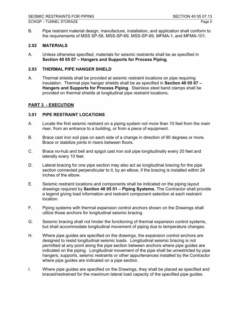
SEISMIC RESTRAINTS FOR PIPING SECTION 40 05 07.13
SCWQP – TUNNEL STORAGE Page 5
B. Pipe restraint material design, manufacture, installation, and application shall conform to the requirements of MSS SP-58, MSS-SP-69, MSS-SP-89, MFMA-1, and MFMA-101.
2.02 MATERIALS
A. Unless otherwise specified, materials for seismic restraints shall be as specified in Section 40 05 07 – Hangers and Supports for Process Piping.
2.03 THERMAL PIPE HANGER SHIELD
A. Thermal shields shall be provided at seismic restraint locations on pipe requiring insulation. Thermal pipe hanger shields shall be as specified in Section 40 05 07 – Hangers and Supports for Process Piping. Stainless steel band clamps shall be provided on thermal shields at longitudinal pipe restraint locations.
PART 3 - EXECUTION
3.01 PIPE RESTRAINT LOCATIONS
A. Locate the first seismic restraint on a piping system not more than 10 feet from the main riser, from an entrance to a building, or from a piece of equipment.
B. Brace cast iron soil pipe on each side of a change in direction of 90 degrees or more. Brace or stabilize joints in risers between floors.
C. Brace no-hub and bell and spigot cast iron soil pipe longitudinally every 20 feet and laterally every 10 feet.
D. Lateral bracing for one pipe section may also act as longitudinal bracing for the pipe section connected perpendicular to it, by an elbow, if the bracing is installed within 24 inches of the elbow.
E. Seismic restraint locations and components shall be indicated on the piping layout drawings required by Section 40 05 01 – Piping Systems. The Contractor shall provide a legend giving load information and restraint component selection at each restraint location.
F. Piping systems with thermal expansion control anchors shown on the Drawings shall utilize those anchors for longitudinal seismic bracing.
G. Seismic bracing shall not hinder the functioning of thermal expansion control systems, but shall accommodate longitudinal movement of piping due to temperature changes.
H. Where pipe guides are specified on the drawings, the expansion control anchors are designed to resist longitudinal seismic loads. Longitudinal seismic bracing is not permitted at any point along the pipe section between anchors where pipe guides are indicated on the piping. Longitudinal movement of the pipe shall be unrestricted by pipe hangers, supports, seismic restraints or other appurtenances installed by the Contractor where pipe guides are indicated on a pipe section.
I. Where pipe guides are specified on the Drawings, they shall be placed as specified and braced/restrained for the maximum lateral load capacity of the specified pipe guides.

SEISMIC RESTRAINTS FOR PIPING SECTION 40 05 07.13
SCWQP – TUNNEL STORAGE Page 6
3.02 INSTALLATION
A. Use rod stiffener assemblies at seismic restraints for hanger rods over 6 inches in length. Use a minimum of two rod stiffener clamps on any rod stiffener assembly.
B. Install lateral and longitudinal bracing between 45 degrees above and 45 degrees below horizontal, inclusive, relative to the horizontal centerline of the pipe.
C. Welded and bolted attachments to the building structural steel shall be in accordance with the requirements of AISC. Do not drill or burn holes in the building structural steel without approval of SPU.
D. Use embedded anchor bolts instead of concrete inserts for seismic brace installations in areas below water surface or normally subject to submerging.
E. Install thermal pipe hanger shields on insulated piping at required locations during restraint installation. Make butt joint connections to pipe insulation at the time of insulation installation in accordance with the manufacturer's recommendations.
F. Restraint components in contact with plastic pipe shall be free of burrs and sharp edges and shall be lined between the pipe and restraint with a layer of rubber sheet.
G. Rollers shall roll freely without binding.
H. Provide plastic or rubber end caps at the exposed ends of all framing channels that are located up to 7 feet above the floor.
3.03 INSPECTION AND CERTIFICATION
A. The Design Professional retained by the Contractor under the provisions of Section 40 05 01 – Piping Systems shall provide inspection and written certification of construction conformance in accordance with Section 40 05 07 – Hangers and Supports for Process Piping requirements.
B. SPU will provide special inspection in accordance with Section 01 73 24 – Design Requirements for Non-Structural Components and Non-Building Structures for piping seismic restraint and bracing systems.
3.04 MEASUREMENT AND PAYMENT
A. Seismic restraints for piping shall not be paid for directly, but shall be considered incidental and included in the lump sum bids for the respective items in the Proposal Schedule.
END OF SECTION 40 05 07.13

EXPANSION CONTROL FOR PIPING SECTION 40 05 07.16SCWQP – TUNNEL STORAGE Page 1
PART 1 - GENERAL
1.01 SECTION INCLUDES
A. Scope:
1. This Section specifies expansion control for the piping systems specified in this Section. This Section addresses pipe anchorage, pipe guides, and expansion control by either expansion joints or pipe deflection.
2. All expansion control components shall be as specified in this Section and Section 40 05 06.23 – Expansion Joints and Flexible Metal Hose.
1.02 REFERENCE STANDARDS
A. REFERENCE STANDARDS: This Section incorporates by reference the latest revisions of the following documents. They are part of this Section insofar as specified and modified herein. In the event of conflict between the requirements of this section and those of the listed documents, the requirements of this Section shall prevail. Unless otherwise specified, references to documents shall mean the documents in effect on the effective date of the Agreement. If referenced documents have been discontinued by the issuing organization, references to those documents shall mean the replacement documents issued or otherwise identified by that organization or, if there are no replacement documents, the last version of the document before it was discontinued.
Reference TitleAISC Manual of Steel Construction
American Institute of Steel Construction, Manual of Steel Construction, Allowable Stress Design - 9th Edition
EJMA-93 Standards of the Expansion Joint Manufacturers Association, Inc., Sixth Edition, 1993
EJMA-85 A Practical Guide to Expansion Joints, Copyright 1985, Expansion Joint Manufacturers Association, Inc.
1.03 DEFINITIONS
A. Definitions:
Term DefinitionExpansion joint Any device containing one or more bellows used to absorb
dimensional changes.Main anchor An attachment between a structure and a pipe which must
withstand the full pipeline thrust due to pressure, pipe bending, pipe compression, flow, spring forces, pipe and contents weight and other pipe forces.
Intermediate anchor An attachment between a structure and a pipe which withstands the same forces as a main anchor except the pressure forces.
Sliding anchor An attachment between a structure and a pipe which absorbs forces in one direction while permitting motion in another.
Pipe guide A device fastened to a structure, which permits the pipeline to move freely in only one direction, along the axis of the pipe.

EXPANSION CONTROL FOR PIPING SECTION 40 05 07.16SCWQP – TUNNEL STORAGE Page 2
Term DefinitionPipe section That portion of pipe between two anchors.Planar pipe guide A device fastened to a structure, which permits transverse
movement or bending of the pipeline in one plane.Lateral direction Direction perpendicular to the pipe axisLongitudinal direction Direction parallel to the pipe axisThrust tie Attachments to expansion joints that allow joint to accommodate
axial thrust due to internal pressure.
1.04 SUBMITTALS
A. Procedures: Section 01 33 10 – Submittals.
B. A copy of this specification section, with addendum updates included, and all referenced and applicable sections, with each paragraph check-marked to indicate compliance or marked to indicate requested deviations.
1.05 SERVICE REQUIREMENTS
A. Operating Conditions:
1. Expansion control as specified in this section shall be provided to control pipe movements and loads occurring as a result of pipeline temperature changes.
2. The Contractor’s Design Professional shall provide expansion control as specified in Section 40 05 01 – Piping Systems. Where expansion control is provided through deflection of the piping and pipe fittings, piping shall be supported and braced such that thermal expansion movement is accommodated without application of excessive loads to piping, supports and bracing.
3. Expansion control provisions are required to accommodate expansion and/or contraction of pipe materials as a result of varying ambient temperature conditions. The Contractor’s pipe hanger and support selection shall accommodate expansion/contraction without interfering with expansion control functions.
4. All piping services are assumed to have operating temperature conditions within the range of ambient temperature conditions. For the purposes of design and/or installing pipe hangers, supports, seismic, bracing, and expansion control components of piping systems, ambient temperature conditions are defined as 20 to 100 degrees Fahrenheit.
5. Until completion of commissioning, the Contractor is responsible for protecting piping systems against damage resulting from expansion or contraction of pipe materials exposed to temperatures outside the ambient temperature condition range.

EXPANSION CONTROL FOR PIPING SECTION 40 05 07.16SCWQP – TUNNEL STORAGE Page 3
PART 2 - PRODUCTS
2.01 MATERIALS
A. Unless otherwise specified, materials for anchors and guides shall be as specified in Section 40 05 07 – Hangers and Supports for Process Piping.
PART 3 - EXECUTION
3.01 INSTALLATION
A. The Contractor shall furnish and install the expansion control system as specified within this Section and in related Sections.
B. Welded and bolted attachments to the building structural steel shall be in accordance with the requirements of the AISC Manual of Steel Construction (allowable stress design). There shall be no drilling or burning of holes in the building structural steel without approval of SPU.
C. Unless otherwise specified, embedded anchor bolts shall be used instead of concrete inserts, wedge anchors, expansion anchors, adhesive, or other non-embedded type of anchor for expansion control installations in areas below water surface or normally subject to submerging. Anchor bolt material and installation shall conform to Section 05 05 20 – Anchor Bolts.
D. The Contractor shall install thermal pipe hanger shields on insulated piping at required locations during guide installation. Butt joint connections to pipe insulation shall be made at the time of insulation installation in accordance with the manufacturer's recommendations.
E. Anchors shall be directly connected to the pipe as designed by the Contractor’s Design Professional.
F. Components in contact with plastic pipe shall be free of burrs and sharp edges.
G. Rollers shall roll freely without binding.
H. Plastic or rubber end caps shall be provided at the exposed ends of all framing channels that are located up to 7 feet above the floor.
3.02 INSPECTION AND CERTIFICATION
A. The Design Professional retained by the Contractor under the provisions of Section 40 05 01 – Piping Systems shall provide inspection and written certification in accordance with Section 40 05 07 – Hangers and Supports for Process Piping requirements.
3.03 MEASUREMENT AND PAYMENT
A. Expansion control for piping shall not be paid for directly, but shall be considered incidental and included in the lump sum bids for the respective items in the Proposal Schedule.
END OF SECTION 40 05 07.16

COPPER PROCESS PIPE AND TUBING SECTION 40 05 17 SCWQP – TUNNEL STORAGE Page 1
PART 1 - GENERAL
1.01 SECTION INCLUDES
A. This section specifies copper piping, tubing, couplings and fittings.
1.02 REFERENCE STANDARDS
A. REFERENCE STANDARDS: This Section incorporates by reference the latest revisions of the following documents. They are part of this Section insofar as specified and modified herein. In the event of conflict between the requirements of this section and those of the listed documents, the requirements of this Section shall prevail. Unless otherwise specified, references to documents shall mean the documents in effect on the effective date of the Agreement. If referenced documents have been discontinued by the issuing organization, references to those documents shall mean the replacement documents issued or otherwise identified by that organization or, if there are no replacement documents, the last version of the document before it was discontinued.
Reference Title
ANSI B16.22 Wrought Copper and Copper Alloy Solder Joint Pressure Fittings
ANSI B16.26 Cast Copper Alloy Fittings for Flared Copper Tubes
ASTM B32 Solder Metal
ASTM B88 Seamless Copper Water Tube
1.03 DEFINITIONS
(NOT USED)
1.04 SUBMITTALS
A. PROCEDURES: Section 01 33 10 – Submittals.
B. A copy of this specification section, with addendum updates included, and all referenced and applicable sections, with each paragraph check-marked to indicate compliance or marked to indicate requested deviations.
C. SUBMITTAL ITEMS:
1. Shop fabrication drawings showing details of materials, piping, fittings, couplings, dielectric connections, joint locations and details, types and locations of supports.
2. Manufacturer’s product data showing conformance of the complete piping system to these specifications.

COPPER PROCESS PIPE AND TUBING SECTION 40 05 17 SCWQP – TUNNEL STORAGE Page 2
PART 2 - PRODUCTS
2.01 COPPER TUBING
A. Copper tubing shall be seamless copper, conforming to ASTM B88. Unless otherwise specified, copper tubing shall be Type L, drawn, where used in exposed service and Type K, annealed or drawn for buried service.
2.02 COUPLINGS AND FITTINGS FOR COPPER TUBING
A. Unless otherwise specified, couplings and fittings for copper tubing 1/2 inch and smaller nominal diameter shall be compression type, brass or bronze, capable of holding the full bursting strength of the tubing; shall meet the requirements of ANSI B16.26; and shall be Swagelok, Gyrolok, or approved equal.
B. Couplings and fittings for copper tubing larger than 1/2-inch nominal diameter shall be wrought copper or bronze, solder joint pressure fittings and shall conform to ANSI B16.22.
2.03 SOLDER
A. Solder to be used in copper piping shall be ASTM B32, Alloy Grade Sn95 or Silvabrite 100.
PART 3 - EXECUTION
3.01 FABRICATION
A. Solder Joints:
1. All pipe and fittings to be jointed with solder shall be free from all burrs and wire brushed or steel wool cleaned. After cleaning, a paste flux shall be evenly and sparingly applied to the surfaces to be joined. Solder shall then be applied and flame passed toward the center of the fitting until the solder disappears. All excess solder shall be removed while it is still plastic. Absolutely no acid flux or acid wipe shall be used in making solder joints.
B. Takedown Couplings:
1. Takedown couplings shall be screw union type and shall be provided in accordance with Section 40 05 06.16 – Piping Connections.
C. Dielectric Protection:
1. Copper tubing or fittings shall not be permitted to come in contact with steel piping, reinforcing steel, or other steel at any location. Electrical checks shall be made to assure no contact is made between copper tubing and steel elements. Wherever electrical contact is demonstrated by such tests, the Contractor shall provide dielectric protection as specified in Section 40 05 06.16 – Piping Connections.

COPPER PROCESS PIPE AND TUBING SECTION 40 05 17 SCWQP – TUNNEL STORAGE Page 3
3.02 INSTALLATION, CLEANING, DISINFECTION, AND TESTING
A. The installation, cleaning, disinfection, and testing of copper piping shall be as specified in Section 40 05 01 – Piping Systems.
END OF SECTION 40 05 17

DUCTILE IRON PROCESS PIPE SECTION 40 05 19SCWQP – TUNNEL STORAGE Page 1
PART 1 - GENERAL
1.01 SECTION INCLUDES
A. Scope: This section specifies ductile iron pipe, fittings and gaskets for ductile piping systems except for water and storm drainage systems. For specifications on ductile iron pipe for water transmission and distribution mains, see Section 33 11 00 – Water Utility Distribution Piping. For specifications on ductile iron pipe for storm drains, see Section 33 40 00 – Storm Drainage Utilities.
1.02 REFERENCE STANDARDS
A. This section contains references to the following documents. They are a part of this section as specified and modified. Where a referenced document contains references to other standards, those documents are included as references under this section as if referenced directly. In the event of conflict between the requirements of this section and those of the listed documents, the requirements of this section shall prevail. Unless otherwise specified, references to documents shall mean the documents in effect at the time of Advertisement for Bids or Invitation to Bid (or on the effective date of the Agreement if there were no Bids). If referenced documents have been discontinued by the issuing organization, references to those documents shall mean the replacement documents issued or otherwise identified by that organization or, if there are no replacement documents, the last version of the document before it was discontinued.
Reference TitleANSI A21.14 Ductile-Iron Fittings 3 In. Through 24 In., for GasANSI A21.52 Ductile-Iron Pipe, Centrifugally Cast, in Metal Molds or Sand Lined Molds for
GasANSI B16.1 Cast Iron Pipe Flanges and Flanged Fittings Class 25, 125, 250, and 800ANSI B16.5 Pipe Flanges and Flanged FittingsASTM A716 Ductile-Iron Culvert PipeASTM C150 Portland CementAWWA C104 (ANSI A21.4)
Cement-Mortar Lining for Ductile- Iron and Gray-Iron Pipe and Fittings for Water
AWWA C110(ANSI A21.10)
Ductile-Iron and Gray-Iron Fittings, 3 In. Through 48 In., for Water and Other Liquids
AWWA C111(ANSI A21.11)
Rubber-Gasket Joints for Ductile- Iron and Gray-Iron Pressure Pipe and Fittings
AWWA C115(ANSI A21.15)
Flanged Ductile-Iron and Gray-Iron Pipe With Threaded Flanges
AWWA C150(ANSI A21.50)
Thickness Design of Ductile-Iron Pipe
AWWA C151(ANSI A21.51)
Ductile-Iron Pipe, Centrifugally Cast, in Metal Molds or Sand-Lined Molds, for Water or Other Liquids
AWWA C153(ANSI A21.53)
Ductile-Iron Compact Fittings, 3 In. Through 12 In. for Water and Other Liquids
AWWA C600 Installation of Ductile-Iron Water Mains and Their AppurtenancesAWWA C606 Grooved and Shouldered Type Joints

DUCTILE IRON PROCESS PIPE SECTION 40 05 19SCWQP – TUNNEL STORAGE Page 2
1.03 SUBMITTALS
A. PROCEDURES: Section 01 33 10 – Submittals.
B. SUBMITTAL ITEMS:
1. A copy of this specification section, with addendum updates included, and all referenced and applicable sections, with each paragraph check-marked to indicate compliance or marked to indicate requested deviations.
2. Manufacturer's product data, catalog cuts, dimensions and materials.
3. Indicate on the submittal each piping system where the product will be used.
4. Certifications indicated in the following documents:
a. ASTM A716, sworn statement of inspection and certification
b. AWWA C110, certification of inspection and testing
c. AWWA C111, record of specified tests
d. AWWA C115, affidavit of compliance
e. AWWA C151, manufacturer’s statement and affidavit of compliance
f. AWWA C153, affidavit of compliance
g. AWWA C606, affidavit of compliance
5. Calculations for alternative anchorage requirements as specified in this Section if alternate anchorage configurations are proposed by the Contractor.
PART 2 - PRODUCTS
2.01 GENERAL
A. Pipe design, materials, and manufacture shall comply with the following documents:
Item DocumentThickness design AWWA C150Manufacturing requirements AWWA C151Gravity service pipe ASTM A716Joints
Rubber gasket AWWA C111Threaded flange AWWA C115Grooved AWWA C606
Fittings AWWA C110/AWWA C153Cement mortar lining AWWA C104Polyethylene encasement AWWA C105

DUCTILE IRON PROCESS PIPE SECTION 40 05 19SCWQP – TUNNEL STORAGE Page 3
2.02 PIPE
A. Unless otherwise specified in the piping system specification sheets (PIPESPEC) in Section 40 05 01 – Piping Systems, ductile iron pipe shall be Pressure Class 350 and have nominal laying lengths of 18 or 20 feet.
B. Pipe wall thickness for grooved-end pipe shall comply with AWWA C606.
C. Pipe wall thickness for glass lined pipe shall not be less than Thickness Class 53 for pipe diameters of 6 inches or greater. 4-inch glass lined pipe shall be Thickness Class 56. Pipe to be bored or machined shall be of a suitable wall thickness to assure boring or machining will not impair minimum wall thickness required for Thickness Class 53.
2.03 FITTINGS
A. Unless otherwise specified on the Drawings, fittings shall conform to AWWA C110 or C153. Fitting ends shall be restrained joints unless otherwise specified in the PIPESPEC. Fitting end joint type shall match pipe end joint type. Long-radius elbows (r approximately 1.5 x D) shall be provided where specified on the Drawings or in the PIPESPEC.
B. Grooved end fittings shall be furnished by the same manufacturer to assure uniformity and compatibility of piping components, fittings and couplings for grooved end piping systems.
2.04 JOINTS
A. UNRESTRAINED JOINTS: No joints shall be unrestrained.
B. RESTRAINED JOINTS:
1. GENERAL: Unless otherwise specified in the PIPESPEC, restrained joints are required for all exposed and buried piping. Unless otherwise specified, restrained joints shall be flanged or grooved end for exposed service and restrained push-on for buried service. Restrained Joints shall be restrained by the interference of metallic rings, bolts, locking segments or other interlocking components with flanges, lugs, beads, grooves or retainer rings that are integrally cast into or welded onto both ends of the joint. Restrained joints with retainer/follower glands and gripping wedges, or gripping gaskets, radial pads, or other devices that penetrate, grip, or embed in the pipe material to resist axial thrust loads are specifically prohibited.
2. RESTRAINED PUSH-ON JOINTS: Restrained push-on joints shall comply with ANSI/AWWA A21.11/C111 and shall be capable of being deflected after full assembly. Joint assembly shall be in strict conformance with AWWA C600 and manufacturer's recommendations. Unless otherwise specified in the PIPESPEC, push-on joints shall have an allowable deflection up to 5 degrees at specified pressures for pipe 12 inch diameter and less. No field cuts of restrained pipe are permitted without prior approval of SPU. Gaskets shall be as specified in ANSI/AWWA A21.11/C111. Candidate manufacturers and products include:
a. American Cast Iron Pipe Company, Flex-Ring or Lok-Ring

DUCTILE IRON PROCESS PIPE SECTION 40 05 19SCWQP – TUNNEL STORAGE Page 4
b. U.S. Pipe, TR Flex or HP LOK
c. Approved substitute
3. FLANGE ASSEMBLIES:
a. Unless otherwise specified on the drawings or in the PIPESPEC, flanges shall be ductile iron and shall be threaded-on flanges conforming to ANSI/AWWA A21.15/C115 or cast-on flanges conforming to ANSI/AWWA A21.10/C110.
b. Flanges shall be adequate for 250 psi working pressure. Bolt circle and bolt holes shall match those of ANSI B16.1, Class 125 flanges and ANSI B16.5, Class 150 flanges.
c. Flange faces shall either be flat flanges or convoluted ring flanges.
1) Flat face flanges: Where companion flanges are used, the flanges on pipe shall be refaced to be flush with the companion flange face. Plain faced flanges shall not be bolted to raised face flanges.
2) Convoluted Ring Flanges: Convoluted ring flanges shall be ductile iron, designed to bear on hubs welded to the pipe and shall be as manufactured by Improved Piping Products. SPU knows of no equal. The flange joints shall be rated for not less than 150 percent of the test pressures listed in Section 40 05 01 – Piping Systems and shall conform to the requirements of ANSI B 16.5 and AWWA C207. The flange manufacturer shall be prepared to demonstrate, by certified pressure test that the flanges will meet these requirements.
d. Gasket material shall be as specified in Section 40 05 01 – Piping Systems.
e. Gaskets for plain faced flanges shall be the full-face gaskets. Thickness shall be 1/16 inch for pipe 10 inches and less in diameter and 1/8 inch for pipe 12 inches and larger in diameter.
f. Unless otherwise specified, gaskets for raised face flanges shall match the raised face and shall be 1/16 inch thick for pipe 3-1/2 inches and less in diameter and 1/8 inch thick for pipe 4 inches and larger.
g. Bolts and nuts shall be Type 316 stainless steel in conformance with ASTM F593 for bolts and ASTM F594 for nuts. Bolts shall be threaded to conform to ANSI B 18.2.1, page C-1 for finished hex bolts. Nuts shall conform to ANSI B18.2.2, page D-1. Bolts and nuts shall be fully passivated. Nuts shall be finished with Tripac 2000 coating system, or approved substitute. All bolt heads and nuts shall be hexagonal. Identification on the head of the bolt shall be T-316, 316, F593G or F593H.

DUCTILE IRON PROCESS PIPE SECTION 40 05 19SCWQP – TUNNEL STORAGE Page 5
h. Where washers are required, they shall be of the same material as the associated bolts.
4. RESTRAINED MECHANICAL JOINTS: Where specified, restrained mechanical joints shall be fully restrained. Fully restrained mechanical joints for above or below ground service shall meet the requirements of ANSI/AWWA A21.10/ C110 and ANSI/AWWA A21.11/C111. Gaskets and bolts and nuts shall be as specified in ANSI/AWWA A21.11/C111. Bolts and nuts shall be Type 316 stainless steel in conformance with ASTM F593 for bolts and ASTM F594 for nuts. Bolts shall be threaded to conform to ANSI B 18.2.1, page C-1 for finished hex bolts. Nuts shall conform to ANSI B18.2.2, page D-1. Bolts and nuts shall be fully passivated. Nuts shall be finished with Tripac 2000 coating system, or approved substitute. All bolt heads and nuts shall be hexagonal. Identification on the head of the bolt shall be T-316, 316, F593G or F593H. Where washers are required, they shall be of the same material as the associated bolts. Note that for metallic pipe the use of add-on restraint devices which employ teeth, set screws, or wedges to grip the pipe similar to Megalug, Stargrip, Romagrip, etc. is expressly forbidden. Candidate manufacturers and products include:
a. American Cast Iron Pipe Company, Mechanical Joint Coupled Joint
b. U.S. Pipe, MJ HARNESS-LOK
c. Approved substitute
5. GROOVED END COUPLINGS: Couplings and wall thickness for grooved end ductile iron pipe shall conform to AWWA C606. Unless otherwise specified in the PIPESPEC, grooved end couplings for ductile iron pipe shall be rigid joint for exposed service and flexible joint for buried service. Grooved End Couplings and gaskets on ductile iron pipe shall conform to AWWA C606. Bolts and nuts shall be Type 316 stainless steel in conformance with ASTM F593 for bolts and ASTM F594 for nuts. Bolts shall be threaded to conform to ANSI B 18.2.1, page C-1 for finished hex bolts. Nuts shall conform to ANSI B18.2.2, page D-1. Bolts and nuts shall be fully passivated. Nuts shall be finished with Tripac 2000 coating system, or approved substitute. All bolt heads and nuts shall be hexagonal. Identification on the head of the bolt shall be T-316, 316, F593G or F593H.
6. GROOVED END FLANGE COUPLING ADAPTERS: Grooved end flanged coupling adapters candidate manufacturers are listed below:
a. Victaulic Style 341
b. Approved substitute
7. GROOVED END TRANSITION COUPLINGS: Grooved end transition couplings to steel pipe candidate manufacturers are listed below:
a. Victaulic Style 307
b. Approved substitute
C. BALL AND SOCKET FLEXIBLE JOINT PIPE: Ball and socket flexible joint pipe shall be the boltless type and shall allow a maximum joint deflection of 15 degrees. Each joint

DUCTILE IRON PROCESS PIPE SECTION 40 05 19SCWQP – TUNNEL STORAGE Page 6
shall be provided with a retainer lock to prevent rotation after assembly. Candidate manufacturers include:
1. American Cast Iron Pipe Company Flex-Lok Joint
2. U.S. Pipe USIflex
3. Approved substitute
2.05 PIPE COATING
A. Unless otherwise specified in the PIPESPEC, exposed pipe and fittings shall be furnished with a factory applied red oxide primer. Coating shall be per Section 09 90 00 - Coatings.
B. Encased pipe and fittings shall be coated with asphaltic material as specified in AWWA C151 and C110 unless otherwise specified in the PIPESPEC.
C. Buried pipe and fittings shall be coated with Type EA-1 coating per Section 09 90 00 - Coatings. Polyethylene encasement per AWWA C105 shall be installed after Type EA-1 coating is applied. No asphaltic coating shall be applied to pipe and fittings requiring Type EA-1 coating.
2.06 PIPE LINING
A. CERAMIC EPOXY LINING: Unless otherwise specified in the PIPESPEC, interior surfaces of pipe and fittings shall be lined with ceramic epoxy. The material shall be amine cured novalac epoxy containing at least 20% by volume of ceramic quartz pigment. Ceramic epoxy shall be Protecto 401 or approved substitute.
B. GLASS LINING:
1. Where specified, pipe and fittings shall be glass lined with a dual layer coating system of vitreous material to a minimum thickness of 10 mils. Glass lining shall provide continuous coverage as tested by a low voltage holiday detector with only isolated voids permitted due to casting anomalies. Voids, other than isolated pinholes, shall be cause for rejection.
2. Glass lined ductile iron pipe shall be bored, machined, or grit blasted to remove any voids, protrusions or surface irregularities to obtain a smooth continuous surface for glass lining. Pipe wall thickness for glass lined pipe shall be as specified in this Section. Fittings shall be ground or grit blasted to remove any voids, protrusions or surface irregularities.
3. Grooves for grooved end fittings shall be installed before glass lining is installed.
4. Field cuts or field installation of grooved ends are not permitted for glass lined pipe.
5. Candidate manufacturers and products for glass lining are listed below:
a. Ferrock MEH-32
b. Vitco SG-14

DUCTILE IRON PROCESS PIPE SECTION 40 05 19SCWQP – TUNNEL STORAGE Page 7
c. Approved substitute.
C. CEMENT MORTAR LINING: Cement mortar lining shall be in accordance with AWWA C104. Cement shall be ASTM C150, Type II or V, low alkali, containing less than 0.60 percent alkalis.
2.07 POLYETHYLENE ENCASEMENT TUBING
A. MATERIALS: Where specified on the Drawings or the PIPESPEC, ductile iron pipe and fittings shall be encased in High Density Polyethylene tubing.
B. CERTIFICATION: Provide certification from an independent laboratory that polyethylene encasement meets the physical properties as listed in AWWA C105.
C. HIGH DENSITY POLYETHYLENE: 4-mil high-density, cross-laminated polyethylene film meeting the requirements of AWWA C105.
PART 3 - EXECUTION
3.01 INSTALLATION
A. GENERAL:
1. Follow piping routes specified on the drawings as closely as possible. Submit proposed deviations in accordance with Section 01 33 10 – Submittals.
2. Install pipe in accordance with AWWA C600.
3. Make connections to existing structures and manholes so that the finished work will conform as nearly as practicable to the requirements specified for the new manholes, including necessary concrete work, cutting and shaping. Shape concrete mortar within any structure and manhole as specified.
B. INSULATING SECTIONS: Where a metallic nonferrous pipe or appurtenance is connected to ferrous pipe or appurtenance, an insulating section shall be provided as specified in Section 40 05 06.16 – Piping Connections.
C. ANCHORAGE: Provide anchorage as specified on the Drawings. Submit calculations and drawings for proposed alternative anchorage in accordance with Section 01 33 10 – Submittals.
3.02 COMPONENT TEST PHASE
A. BURIED PIPING: Conduct hydrostatic pressure tests in accordance with Section 5 of AWWA C600 except that test pressures and allowable leakage shall be as listed in Section 40 05 01 – Piping Systems.
B. EXPOSED AND CONCRETE ENCASED PIPING: Conduct hydrostatic pressure tests in accordance with procedures and allowable leakage as specified in Section 40 05 01 – Piping Systems.
C. NOTICE: The Contractor shall notify SPU 48 hours prior to each test and conduct the tests in the presence of SPU.

DUCTILE IRON PROCESS PIPE SECTION 40 05 19SCWQP – TUNNEL STORAGE Page 8
3.03 POLYETHYLENE ENCASEMENT
A. GENERAL: Where specified, use polyethylene encasement for buried ductile iron pipe. Install polyethylene as specified in AWWA C105 and within this Section.
B. POTABLE WATER PIPE: Single wrap, 4-mil high density polyethylene.
C. WRAPPING:
1. Wrap buried pipe, fittings, valves, and couplings.
2. Prior to the placing of concrete, wrap fittings that require concrete backing.
3. Wrap the polyethylene tube seams and overlaps and hold in place by means of a 2-inch-wide plastic backed adhesive tape.
4. Tape:
a. The tape shall be such that the adhesive shall bond securely to both metal surfaces and polyethylene film.
b. Acceptable manufacturers:
1) Polyken No. 900 (polyethylene).
2) Scotchwrap No. 50 (polyvinyl).
3) Approved substitute.
5. Bedding and initial backfill for polyethylene wrapped pipe shall be a well-graded granular material to avoid cutting or damaging the polyethylene tube during placement and backfilling.
END OF SECTION 40 05 19

HYDRAULIC SERVICE STAINLESS STEEL PIPE SECTION 40 05 22SCWQP – TUNNEL STORAGE Page 1
PART 1 – GENERAL
1.01 SECTION INCLUDES
A. This Section specifies the work necessary to furnish and install stainless steel pipe and fittings for hydraulic pressure service.
1.02 REFERENCE STANDARDS
A. References: This section contains references to the following documents. They are a part of this section as specified and modified. Where a referenced document contains references to other standards, those documents are included as references under this section as if referenced directly. In the event of conflict between the requirements of this section and those of the listed documents, the requirements of this section shall prevail. Unless otherwise specified, references to documents shall mean the documents in effect at the time of Advertisement for Bids or Invitation to Bid (or on the effective date of the Agreement if there were no Bids). If referenced documents have been discontinued by the issuing organization, references to those documents shall mean the replacement documents issued or otherwise identified by that organization or, if there are no replacement documents, the last version of the document before it was discontinued.
Reference TitleASME B1.20.1 Pipe Threads, General PurposeASME B16.11 Forged Steel Fittings, Socket Welding and ThreadedASME B31.3 Process PipingASME Section IX Boiler and Pressure Vessel Code Welding and Brazing
QualificationsASTM A182 Forged or Rolled Alloy-Steel Pipe Flanges, Forged Fittings, and
Valves and Parts for High-Temperature ServiceASTM A312 Seamless and Welded Austenitic Stainless Steel Pipes
B. All tools shall be made of materials formulated for working with stainless steel. The use of carbon steel tools is prohibited.
C. All welds, including tack welds, shall conform to the requirements of ASME Section IX.
D. All welding shall be by ASME certified welders.
E. Welding procedures shall meet the qualification requirements of ASME Section IX.
1.04 SUBMITTALS
A. Procedures: Section 01 33 10 -- Submittals.
B. A copy of this specification section, with addendum updates included, and all referenced and applicable sections, with each paragraph check-marked to indicate compliance or marked to indicate requested deviations.
B. Submittal Items:

HYDRAULIC SERVICE STAINLESS STEEL PIPE SECTION 40 05 22SCWQP – TUNNEL STORAGE Page 2
1. Layout drawings and catalog data demonstrating compliance with this Specification and giving full description of the copper piping.
2. Welding/welding operator qualifications.
3. Welding procedures.
PART 2 – PRODUCTS
2.01 PIPE
A. ASTM A312, Type 316L, Schedule 80, seamless, annealed, pickled and passivated, ends capped in mill.
2.02 CONNECTIONS
A. Socket welded with taper threaded adapters for valves and other appurtenances. Taper threads shall comply with ASME B1.20.1
2.03 COUPLINGS AND FITTINGS
A. Material: ASTM A182, Grade F316L.
B. Welded: Forged socket weld type, ASME B16.11, Class 3000.
C. Threaded: Forged, ASME B16.11, Class 2000.
2.04 UNIONS
A. Flat-faced O-ring type for both regular and dielectric (insulating) unions
2.05 CORROSION PROTECTION
A. Cathodic Protection: In accordance with manufacturer’s recommendations and as shown on the Drawings.
B. Protective Wrap:
1. Buried piping shall be single wrapped with 10 mil polyethylene Scotchwrap by 3M Company. Apply per manufacturer's instructions.
2. Buried connection between steel pipe and stainless steel pipe shall be double wrapped in opposite directions. Double wrap shall extend 12 inches on either side of the connection.
PART 3 – EXECUTION
3.01 GENERAL
A. Install piping in accordance with Section 40 05 01 – Piping Systems.

HYDRAULIC SERVICE STAINLESS STEEL PIPE SECTION 40 05 22SCWQP – TUNNEL STORAGE Page 3
3.02 WELDING
A. General: In accordance with ASME Section IX and ASME B31.3.
B. End Preparation: Prepare pipe edges preferably by machine shaping or cutting with an aluminum oxide blade. Oxygen or arc cutting are acceptable only if the cut is reasonably smooth and true and all slag is removed either by chipping or grinding.
C. Cleaning: Clean surfaces and make free of paint, oil, scale, slag, or other material detrimental to welding. Prior to welding, wire brush joints with stainless steel wire brushes or stainless steel wool.
D. Procedure:
1. Use the shielded metal-arc process for all field welding. Shop fabrication shall be in accordance with the submitted welding procedure qualifications.
2. Perform no welding if there is impingement of any rain, snow, sleet, or high wind on the weld area, or if the ambient temperature is below 32 degrees F. If the ambient is less than 32 degrees F, local preheating to a temperature warm to the hand is required.
3. Tack welds which are not removed shall be made with an electrode that is the same as or equivalent to the electrode to be used for the first weld pass, shall occur within the weld area and shall not exceed the size of the completed weld. Thoroughly clean tack welds to avoid porosity in the cover pass.
4. Remove tack welds if not made by a qualified welder using the same procedure as for the completed weld. Remove cracked tack welds. Grind down to clean metal those areas to be repaired and perform repair by building up with weld metal. Grind the repaired areas smooth to form a plane surface with the base metal.
5. Use a minimum of three weld passes for butt-weld joints using the specified electrode. Thoroughly clean each layer of deposited weld metal prior to the deposition of each additional layer of weld metal, including the final pass, with a power-driven wire brush. Chip or grind out surface defects which will affect the soundness of weld.
6. Remove welds with cracks, slag inclusions, excessive weld reinforcement, porosity, undercutting, incomplete penetration, and other defects in excess of the limits prescribed in Chapter V of ANSI B31.3 or which are otherwise deficient in quality or made contrary to any provisions of these specifications, by chipping or grinding throughout their depth to clean base metal. Perform no calking or peening of welds to correct defects. Enlarge welds that are found deficient in dimension but not in quality by additional welding after thoroughly cleaning the surface of previously deposited metal and the adjoining plate.
7. Remove excessive weld deposits, slag, spatter, and projections by grinding.
8. Remove all residue, oxide, and heat stain from any type of weld and the affected areas adjacent by the use of stainless steel wire brushes, followed by cleaning with an agent such as Eutectic Company's Eucleen or approved equal, followed by complete removal of the agent.

HYDRAULIC SERVICE STAINLESS STEEL PIPE SECTION 40 05 22SCWQP – TUNNEL STORAGE Page 4
3.03 REPAIR
A. Patching inserts, overlays, or pounding out of dents will not be permitted. Remove damaged ends as a cylinder and properly prepare the section end.
3.04 FIELD TESTING
A. Testing of Welds: Engineer will employ the services of a certified welding inspector to visually inspect the welds. All welded joints will be visually inspected after final weld pass and final grinding. In addition, all joints to be field welded shall be visually inspected after alignment (and tack weld where appropriate) and before the first weld pass. Contractor shall give the Engineer 48 hours advance notice of readiness for inspection. Welds repaired as a result of weld inspection or hydrostatic testing shall be reinspected at the Contractor's expense.
B. Test all lines hydrostatically in accordance with Section 40 05 01 – Piping Systems.
3.05 CLEANING
A. Comply with Section 40 05 01 – Piping Systems.
END OF SECTION 40 05 22

STAINLESS STEEL PROCESS PIPE AND TUBING SECTION 40 05 23SCWQP – TUNNEL STORAGE Page 1
PART 1 – GENERAL
1.01 SECTION INCLUDES
A. This Section specifies stainless steel pipe and fittings.
1.02 REFERENCE STANDARDS
A. References: This section contains references to the following documents. They are a part of this section as specified and modified. Where a referenced document contains references to other standards, those documents are included as references under this section as if referenced directly. In the event of conflict between the requirements of this section and those of the listed documents, the requirements of this section shall prevail. Unless otherwise specified, references to documents shall mean the documents in effect at the time of Advertisement for Bids or Invitation to Bid (or on the effective date of the Agreement if there were no Bids). If referenced documents have been discontinued by the issuing organization, references to those documents shall mean the replacement documents issued or otherwise identified by that organization or, if there are no replacement documents, the last version of the document before it was discontinued.
Reference TitleANSI B31.3 Process PipingASME Section IX Boiler and Pressure Vessel Code; Welding and Brazing RequirementsASTM A480 General Requirements for Flat-Rolled Stainless and Heat-Resisting Steel
Plate, Sheet, and StripAWWA M11 Steel Pipe-A Guide for Design and InstallationAWWA C227 Bolted, Split-Sleeve Restrained and Non-Restrained Couplings for Plain-
End PipeAWWA C606 Grooved and Shouldered JointsCSA W48.3 Low Alloy Steel Covered Electrodes for Shielded Metal Arc Welding
1.03 DEFINITIONS
(NOT USED)
1.04 SUBMITTALS
A. PROCEDURES: Section 01 33 10 – Submittals.
B. A copy of this specification section, with addendum updates included, and all referenced and applicable sections, with each paragraph check-marked to indicate compliance or marked to indicate requested deviations.
C. SUBMITTAL ITEMS:
1. A copy of this Section, addendum updates included, with each paragraph check-marked to indicate compliance or marked to indicate requested deviations from Section requirements.

STAINLESS STEEL PROCESS PIPE AND TUBING SECTION 40 05 23SCWQP – TUNNEL STORAGE Page 2
2. Piping layout drawings as specified in Section 40 05 01 – Piping Systems.
3. Manufacturers’ product data, catalog cuts, typical installation details, and dimensions. Indicate on the submittal each piping system where the product will be used.
4. Pipe wall thickness calculations for pipe fabricated per AWWA C220. Demonstrate the maximum permissible internal design pressure in the pipe based on the wall/shell thickness specified in the Piping System Schedule for the associated Process Service and pipe size and the support and/or bedding conditions specified on the Drawings. Steel pipe design calculations conform to AWWA M11.
5. Pipe wall thickness and reinforcement calculations for fittings fabricated per AWWA C226. Demonstrate that the maximum permissible internal design pressure for fabricated fittings matches or exceeds the maximum permissible internal design pressure in the connecting pipe for the support and/or bedding conditions specified on the Drawings. Fabricated steel pipe fitting design calculations conform to AWWA M11. Calculations for any pipe and fittings that are not fabricated per one of the components standards listed in the specified ASME B31 code.
6. Manufacturers’ certificates of compliance with specified industry standards.
1.05 DELIVERY, STORAGE, AND HANDLING
A. Procedures: Section 01 66 00 – Product Storage and Handling Requirements.
B. Deliver pipe and fittings with end protectors in place. Do not remove protectors until materials are about to be installed.
C. Prevent carbon steel contamination of stainless steel pipe and fittings during storage, handling, fabrication, and installation.
PART 2 – PRODUCTS
2.01 MATERIALS
A. All pipe system materials to be new, free from defects and conforming to the requirements and standards specified in Section 40 05 01 – Piping Systems and this Section.
B. Pipe:
1. Use pickled and annealed sheet or plate for manufacture of fabricated stainless steel pipe.
2. Finish.
a. 8-gage through 16-gage material: No. 1 or 2B per ASTM A480.

STAINLESS STEEL PROCESS PIPE AND TUBING SECTION 40 05 23SCWQP – TUNNEL STORAGE Page 3
b. 3/16-inch and heavier plate material: No. 1 mill finish per ASTM A480, “Hot-Rolled or Cold-Rolled, and Annealed or Heat Treated, and Blast Cleaned or Pickled.”
C. Shop-fabricated stainless steel pipe and fittings:
1. Furnished by a single manufacturer who is experienced and qualified in the manufacture and fabrication of the items to be provided.
2. Manufacture using Weld Procedure Specifications (WPS) that have been qualified under ASME Section IX. Document qualifications in Procedure Qualification Reports (PQR). Use only certified welders who have successfully completed performance qualification tests per ASME Section IX for manufacture of stainless steel pipe.
D. Fittings:
1. Double ferrule compression fittings capable of holding the full bursting pressure of connected tubing.
2. Candidate manufacturers for double ferrule compression fittings.
a. Swagelok.
b. Gyrolok.
c. Approved Equal.
3. Provide straight tapered reducers. Flanged & flued reducers and bushing type adapters are not permitted.
4. Pressure rating and thickness of elbows, tees, crosses, and wyes equal to or greater than connecting pipe.
E. Grooved couplings and fittings:
1. Flexible and rigid coupling with pipe grooves compliant with AWWA C606.
2. When pipe wall thickness does not meet the minimum requirements of AWWA C606 for rolled or cut groove joints, provide shoulder ends per the requirements of AWWA C606.
3. Candidate manufacturers.
a. Victaulic
b. Gruvlok
c. Approved equal.
F. Bolted split sleeve couplings.

STAINLESS STEEL PROCESS PIPE AND TUBING SECTION 40 05 23SCWQP – TUNNEL STORAGE Page 4
1. AWWA C227 compliant sleeve with single or double arch cross section of the same material as pipe. Body thickness equal to or greater than that of connecting pipe wall thickness.
2. Candidate manufacturers.
a. Victaulic, Style 231S through 234S.
b. Approved equal.
2.02 SHOP FABRICATION
A. Metal forming processes.
1. Use pinch rolls with a hard chrome finish to form cylinders. Thoroughly clean the rolls using Avesta BlueOneTM 130 Pickling Paste or approved equal, prior to roll forming the pipe. Alternatively, provide a protective barrier between the stainless steel plate/sheet and the plate rolls during the forming process.
2. Provide a protective barrier between pipe welding rollers and the stainless steel pipe cylinder. Alternately, new rollers or rollers that have been turned down on a lathe to provide a new and clean working face may be used.
B. All saws, drills, files, wire brushes, grinding wheels, etc. will be free of carbon contamination and designated for stainless steel use only.
C. Provide nonferrous, stainless steel, or rubber-lined pipe storage and fabrication racks.
D. Use nylon slings or straps for handling stainless steel piping.
E. Preparation of surfaces to be welded.
1. Surfaces of joints to be welded are to be free from mill scale, slag, grease, oil, paint, rust, and other foreign material.
2. Use only stainless wire wheels and grinding wheels that have not come into contact with carbon steel.
3. Flame cutting or any use of oxy-acetylene gas cutting tools is prohibited. Use plasma arc torch with a nitrogen or argon-hydrogen carrier gas, laser or waterjet processes for cutting and plate beveling.
4. Air arc and gas backgouging are prohibited. Use grinding and plasma gouging methods to achieve full penetration welds.
F. Welding:
1. Welding and production processes are to conform to ASME B31.3.
2. Use of Solar Flux is prohibited.
3. Use of FCAW welding is prohibited.

STAINLESS STEEL PROCESS PIPE AND TUBING SECTION 40 05 23SCWQP – TUNNEL STORAGE Page 5
4. Pipe and fittings with wall thickness up to 11-gage (1/8-inch): weld using the GTAW process.
5. Pipe and fittings with wall thicknesses greater than 1/4-inch may be welded using an automated SAW process.
6. Pipe and fittings with wall thickness greater than 11-gage (1/8-inch): Bevel and complete root pass using the GTAW process, followed by subsequent passes with the GTAW, GMAW, or Metallic Arc SMAW process.
7. Filler material:
a. Add only ELC wire grades to provide a cross section at the weld equal to or greater than the parent metal.
b. SMAW electrodes to conform to CSA W48.3.
8. Make weld deposit smooth and evenly distributed and with a crown of no more than 1/16-inch on the I.D. and 3/32-inch on the O.D. of the piping. Concavity, undercut, cracks, or crevices are not permitted.
9. Full penetration butt welds: provide inert gas shielding to the interior and exterior of the joint.
10. Lap joints: provide full thickness seal welds on both joints.
G. Remove excessive weld deposits, slag, spatter, and projections by grinding. Grind welds smooth on gasket surfaces. Tack welds, clips, and other attachments.
1. Repair nicks, gouges, notches, and depressions in the base metal in the area before the joint weld is made.
2. Remove tack welds, clips, and other attachments and repair defects, except where the tack welds occur within the weld area and these tack welds do not exceed the size of the completed weld. Remove cracked tack welds.
3. Grind those areas to be repaired down to clean metal and then repair by building up with weld metal. Grind the repaired areas smooth to form a plane surface with the base metal.
H. Defects and repairs:
1. Remove welds with cracks, slag inclusions, porosity, undercutting, incomplete penetration, or which are otherwise deficient in quality or made contrary to any provisions of these specifications, by chipping or grinding throughout their depth to clean base metal.
2. Do not perform calking or peening of welds to correct defects.
3. Enlarge welds found deficient in dimension but not in quality by additional welding after thoroughly cleaning the surface of previously deposited metal and the adjoining plate.

STAINLESS STEEL PROCESS PIPE AND TUBING SECTION 40 05 23SCWQP – TUNNEL STORAGE Page 6
4. Remove weld deposits, slag, weld spatter, and projections into the interior of the pipe by grinding.
I. Finish:
1. Treat all welded joints with Avesta BlueOneTM 130 Pickling Paste or approved equal and rinse with clean water.
2. If rusting of embedded iron occurs, pickle the affected surface with Avesta BlueOneTM 130 Pickling Paste or approved equal.
3. Rinse clean using Avesta FinishOne Passivator 630 or approved equal.
PART 3 – EXECUTION
3.01 GENERAL
A. Field Installation Weather conditions:
1. Perform welding only when the surfaces are clean and completely free of any moisture or mineral deposits. Protect pipe and fittings from salt water spray or deposition or clean and protect pipe and fitting joints prior to welding.
2. Do not weld the pipe during periods of high winds or rain unless the areas being welded are properly shielded.
B. Field welding:
1. Use couplings and prefabrication of pipe systems at the factory to minimize field welding to the greatest extent possible. Pipe butt welds may be performed at the job site, providing the butt welds are performed only with an inert gas shielded process and that the welding requirements of this Section are rigidly adhered to.
2. On the interior and exterior of the pipe, remove all residue, oxide, and heat stain from any type of field weld and the affected areas adjacent by the use of stainless steel wire brushes, followed by cleaning with an agent such as Avesta BlueOneTM 130 or approved equal, followed by complete removal of the agent.
C. Use wooden scaffolding and/or ladders if possible to gain access to work areas. If metal scaffolding and/or ladders must be used, tape or otherwise shield the contact points between scaffolding/ladders and the stainless steel.
D. After installation, wash and rinse all foreign matter from the piping surface. Adhere to the passivation manufacturer’s recommendations and local regulations for safety and disposal of any waste chemicals.
3.02 REPAIR/RESTORATION
A. Per Section 40 05 01 – Piping Systems and as specified herein.

STAINLESS STEEL PROCESS PIPE AND TUBING SECTION 40 05 23SCWQP – TUNNEL STORAGE Page 7
B. Paint all steel or iron flanges, couplings, and appurtenances in accordance with Section 09 90 00 – Coatings. Painting of the stainless steel pipe is not required.
C. Restore areas damaged or discolored by field welding or handling, iron contamination or soiled to a uniform surface finish and consistently clean surface with methods specified for shop fabrication.
D. Identifying spool piece marks shall be removed with paint thinner or solvents and the entire stainless steel surface shall be washed with detergent and hot water and rinsed clean.
3.03 COMPONENT TEST PHASE
A. Per Section 40 05 01 – Piping Systems.
3.04 MEASUREMENT AND PAYMENT
A. Stainless steel process pipe and tubing shall not be paid for directly, but shall be considered incidental and included in the lump sum bids for the respective items in the Proposal Schedule.
END OF SECTION 40 05 23

STEEL PROCESS PIPE SECTION 40 05 24
SCWQP – TUNNEL STORAGE Page 1
PART 1 – GENERAL
1.01 SECTION INCLUDES
A. This section specifies steel pipe and fittings.
1.02 REFERENCE STANDARDS
A. References: This section contains references to the following documents. They are a part of this section as specified and modified. Where a referenced document contains references to other standards, those documents are included as references under this section as if referenced directly. In the event of conflict between the requirements of this section and those of the listed documents, the requirements of this section shall prevail. Unless otherwise specified, references to documents shall mean the documents in effect at the time of Advertisement for Bids or Invitation to Bid (or on the effective date of the Agreement if there were no Bids). If referenced documents have been discontinued by the issuing organization, references to those documents shall mean the replacement documents issued or otherwise identified by that organization or, if there are no replacement documents, the last version of the document before it was discontinued. Where document dates are given in the following listing, references to those documents shall mean the specific document version associated with that date, regardless of whether the document has been superseded by a version with a later date, discontinued or replaced.
Reference Title
ANSI B16.3 Malleable Iron Threaded Fittings, Class 150 and 300
ANSI B16.9 Factory-Made Wrought Steel Buttwelding Fittings
ANSI B16.11 Forged Steel Fittings, Socket-Welding and Threaded
ASTM A36/A36M Structural Steel
ASTM A47 Ferritic Malleable Iron Castings
ASTM A53 Pipe, Steel, Black and Hot-Dipped, Zinc-Coated Welded and Seamless
ASTM A105/A105M Forgings, Carbon Steel, for Piping Components
ASTM A106 REV A Seamless Carbon Steel Pipe for High-Temperature Service
ASTM A197 Cupola Malleable Iron
ASTM A234/A234M Pipe Fittings of Wrought Carbon Steel and Alloy Steel for Moderate and Elevated Temperatures
ASTM A283/A283M REV A
Low and Intermediate Tensile Strength Carbon Steel Plates, Shapes and Bars
ASTM A536 Ductile Iron Castings

STEEL PROCESS PIPE SECTION 40 05 24
SCWQP – TUNNEL STORAGE Page 2
Reference Title
ASTM A570/A570M Hot-Rolled Carbon Steel Sheet and Strip, Structural Quality
ASTM A572/A572M REV B
High Strength Low Alloy Columbium-Vanadium Steels of Structural Quality
AWWA C200 Steel Water Pipe 6 Inches and Larger
AWWA C205 Cement-Mortar Protective Lining and Coating for Steel Water Pipe--4 In. and Larger-- Shop Applied
AWWA C206 Field Welding of Steel Water Pipe
AWWA C207 Steel Pipe Flanges for Waterworks Services--Sizes 4 In. Through 144 In.
AWWA C208 Dimensions for Fabricated Steel Water Pipe Fittings
AWWA C209 Cold-Applied Tape Coating for Special Sections, Connections, and Fittings for Steel Water Pipelines
AWWA C210 Liquid Epoxy Coating Systems for the Interior and Exterior of Steel Water Pipe
AWWA C214 Tape Coating Systems for the Exterior of Steel Water Pipelines
AWWA C600 Installation of Ductile-Iron Water Mains and Their Appurtenances
AWWA M11 Steel Pipe--A Guide for Design and Installation
SSPC-SP10 Near-White Blast Cleaning
1.03 DEFINITIONS
(NOT USED)
1.04 SUBMITTALS
A. PROCEDURES: Section 01 33 10 – Submittals.
B. A copy of this specification section, with addendum updates included, and all referenced and applicable sections, with each paragraph check-marked to indicate compliance or marked to indicate requested deviations.
C. SUBMITTAL ITEMS:
1. A copy of this Section with each paragraph check-marked to indicate compliance or marked to indicate requested deviations.
2. Affidavits of Compliance with AWWA C200, ASTM A53, or ASTM A106 as applicable.

STEEL PROCESS PIPE SECTION 40 05 24
SCWQP – TUNNEL STORAGE Page 3
3. Contractor's layout drawings as specified in Section 40 05 01 – Piping Systems.
1.05 QUALITY ASSURANCE
A. Testing:
1. Factory testing shall conform to the requirements of ASTM A53, ASTM A106, or AWWA C200 as applicable.
PART 2 – PRODUCTS
2.01 PIPE MATERIALS
A. Steel pipe and fittings shall be provided in accordance with ASTM A53, ASTM A106, or AWWA C200 as specified in Section 40 05 01 – Piping Systems.
B. Steel for pipe fabricated to meet requirements of AWWA C200 shall conform to the requirements of ASTM A36, ASTM A572, Grade 42, ASTM A570, Grades 33 and 36, or ASTM A283, Grade D. Steel for ASTM A53 and ASTM A106 pipe shall be Grade B.
2.01 PIPE MANUFACTURE
A. Unless otherwise specified, ASTM A53 pipe shall be Type E, electric resistance welded or Type S, seamless pipe as specified in Section 40 05 01 – Piping Systems. The minimum wall thickness for ASTM A53 or ASTM A106 pipe shall be Schedule 40 for pipe 10 inch diameter and less and 3/8 inch for pipe 12 inch through 24 inch diameter. Increased shell thickness shall be provided where specified.
B. AWWA C200 pipe shall be straight or spiral seam. The minimum wall thickness shall be 7 gage for pipe 6 inch through 24 inch diameter and 1/4 inch for pipe 26 inch diameter and larger. Increased shell thickness shall be provided where specified.
2.02 CONNECTIONS
A. Connections shall be as specified in Section 40 05 01 – Piping Systems and shall conform to Section 40 05 06.16 – Piping Connections. Coating for buried connections shall be as specified in Section 40 05 06.16 – Piping Connections.
2.03 FITTINGS AND APPURTENANCES
A. Malleable iron threaded fittings and appurtenances shall conform to the requirements of ASTM A47 or ASTM A197, ANSI B16.3.
B. Unless otherwise specified, steel fittings and appurtenances shall conform to the requirements of ASTM A234, ASTM A105, or ANSI B16.11; and fabricated steel fittings and appurtenances shall conform to AWWA C208.
C. Fittings for grooved end piping systems shall be full flow cast fittings, steel fittings, or segmentally welded fittings with grooves or shoulders designed to accept grooved end

STEEL PROCESS PIPE SECTION 40 05 24
SCWQP – TUNNEL STORAGE Page 4
couplings. Cast fittings shall be cast of ductile iron conforming to ASTM A536 or malleable iron conforming to ASTM A47. Standard steel fittings, including large size elbows, shall be forged steel conforming to ASTM A106. Standard segmentally welded fittings shall be fabricated of Schedule 40 carbon steel pipe.
D. Unless otherwise specified, all fittings shall be rated for pressure and loadings equal to the pipe.
2.04 PIPE LINING
A. Epoxy:
1. Unless otherwise specified, pipe and fittings shall be lined with a liquid epoxy as specified in AWWA C210 with the following exceptions:
a. No coal tar products shall be incorporated in the liquid epoxy.
b. The curing agent may be an amidoamine as well as the other curing agents listed in AWWA C210.
2. The lining shall be applied to a minimum thickness of 16 mils in not less than two coats.
B. Cement Mortar:
1. Where specified, pipe and fittings shall be lined with cement mortar as specified in AWWA C205. Fittings and specials larger than 24 inches, not fabricated from centrifugally lined straight sections, shall require 2-inch by 4-inch by 13-gage self-furring wire mesh reinforcement for hand-applied lining.
C. Glass Lining:
1. Where specified, pipe and fittings shall be glass lined with a dual layer coating system of vitreous material to a minimum thickness of 10 mils. Glass lining shall provide continuous coverage as tested by a low voltage holiday detector with only isolated voids permitted due to casting anomalies. Voids, other than isolated pinholes, shall be cause for rejection.
2. Pipe and fittings shall have all internal welds ground smooth and any voids or slag holes ground out, rewelded and ground smooth.
3. Glass lining shall be Ferrock MEH-32, Vitco SG-14, or approved equal.
2.05 PIPE COATING
A. Epoxy:
1. Unless otherwise specified, pipe and fittings shall be coated with a liquid epoxy as specified in AWWA C210 with the following exceptions:
a. No coal tar products shall be incorporated in the liquid epoxy.

STEEL PROCESS PIPE SECTION 40 05 24
SCWQP – TUNNEL STORAGE Page 5
b. The curing agent may be an amidoamine as well as the other curing agents listed in AWWA C210.
2. The coating shall be applied to a minimum thickness of 16 mils in not less than two coats.
B. Polyethylene Tape:
1. Where specified, pipe and fittings shall be coated and wrapped with prefabricated multilayer cold applied polyethylene tape coating in accordance with AWWA C214. The coating application shall be a continuous step operation in conformance with AWWA C214, Section 3. The total coating thickness shall be not less than 50 mils for pipe 24 inches and smaller and not less than 80 mils for pipe 26 inches and larger.
2.06 FUSION EPOXY COATING AND LINING
A. Where specified, steel pipe and fittings shall be fusion epoxy coated and lined. The fusion epoxy coating shall be 3M Scotchkote 203, or approved equal. Surface preparation shall be in accordance with SSPC-SP 10 Near White Blast Cleaning. The application method shall be by the fluidized bed method and shall attain 12 mils minimum dry film thickness.
B. Field welds, connections and otherwise damaged areas shall be coated and patched according to the manufacturer's instructions with 3M Scotchkote 306.
PART 3 – EXECUTION
3.01 INSTALLATION
A. General:
1. Pipe shall be installed in accordance with AWWA M11, Chapter 16. Welded joints shall be in accordance with AWWA C206 and Section 40 05 06.16 – Piping Connections.
2. Sleeve-type mechanical pipe couplings shall be provided in accordance with AWWA M11 and Section 40 05 06.16 – Piping Connections.
3. Pipe lining and coatings at field joints shall be applied as specified in this Section.
4. Unless otherwise specified, buried mechanical couplings and valves shall be field coated as specified in Section 40 05 06.16 – Piping Connections.
B. Anchorage:
1. Anchorage shall be provided as specified. Calculations and drawings for proposed alternative anchorage shall be submitted in accordance with Section 01 33 10 – Submittals.

STEEL PROCESS PIPE SECTION 40 05 24
SCWQP – TUNNEL STORAGE Page 6
3.02 TESTING
A. Hydrostatic testing shall be in accordance with Section 4 of AWWA C600 except that test pressures and allowable leakage shall be as listed in Section 40 05 01 –Piping Systems.
END OF SECTION 40 05 24

THERMOPLASTIC PROCESS PIPE SECTION 40 05 31SCWQP – TUNNEL STORAGE Page 1
PART 1 – GENERAL
1.01 SECTION INCLUDES
A. Scope: This section specifies polyvinylchloride pipe and fittings. High density polyethylene (HDPE) piping for air service is specified in Section 40 05 33.13 – HDPE Pipe for Air Service.
B. Pipe Designations: For use in the Piping System Specification Sheets (PIPESPEC) in Section 40 05 01 – Piping Systems and in this section, the following plastic pipe designations are defined:
Designation DefinitionPVC Polyvinylchloride
1.02 REFERENCE STANDARDS
A. References:
1. This section contains references to the following documents. They are a part of this section as specified and modified. Where a referenced document contains references to other standards, those documents are included as references under this section as if referenced directly. In the event of conflict between the requirements of this section and those of the listed documents, the requirements of this section shall prevail.
2. Unless otherwise specified, references to documents shall mean the documents in effect at the time of Advertisement for Bids or Invitation to Bid (or on the effective date of the Agreement if there were no Bids). If referenced documents have been discontinued by the issuing organization, references to those documents shall mean the replacement documents issued or otherwise identified by that organization or, if there are no replacement documents, the last version of the document before it was discontinued. Where document dates are given in the following listing, references to those documents shall mean the specific document version associated with that date, regardless of whether the document has been superseded by a version with a later date, discontinued or replaced.
Reference TitleASTM D1248 Polyethylene Plastics Molding and Extrusion MaterialsASTM D1784 Rigid Poly (Vinyl Chloride) (PVC) Compounds and
Chlorinated Poly (Vinyl Chloride) (CPVC) CompoundsASTM D1785 Poly (Vinyl Chloride) (PVC) Plastic Pipe, Schedules 40,
80, and 120ASTM D2241 Poly (Vinyl Chloride) (PVC) Plastic Pipe (SDR-PR)ASTM D2464 Threaded Poly (Vinyl Chloride) (PVC) Plastic Pipe Fittings,
Schedule 80ASTM D2466 Poly (Vinyl Chloride) (PVC) Plastic Pipe Fittings, Schedule
40

THERMOPLASTIC PROCESS PIPE SECTION 40 05 31SCWQP – TUNNEL STORAGE Page 2
Reference TitleASTM D2467 Socket-Type Poly (Vinyl Chloride) (PVC) Plastic Pipe
Fittings, Schedule 80ASTM D2564 Solvent Cements for Poly (Vinyl Chloride) (PVC) Plastic
Pipe and FittingsASTM D2665 Poly (Vinyl Chloride) (PVC) Plastic Drain, Waste, and Vent
Pipe and FittingsASTM D4101 Propylene Plastic Injection and Extrusion MaterialsASTM F402 Safe Handling of Solvent Cements and Primers Used for
Joining Thermoplastic Pipe and FittingsASTM F477 Elastomeric Seals (Gaskets) for Joining Plastic Pipe
1.03 DEFINITIONS
(NOT USED)
1.04 SUBMITTALS
A. PROCEDURES: Section 01 33 10 – Submittals.
B. A copy of this specification section, with addendum updates included, and all referenced and applicable sections, with each paragraph check-marked to indicate compliance or marked to indicate requested deviations.
C. SUBMITTAL ITEMS:
1. Manufacturer's certificates of compliance with the specified standards and Contractor's layout drawings.
2. Contractor’s layout drawings as specified in Section 40 05 01 – Piping Systems.
PART 2 – PRODUCTS
2.01 PVC PIPE
A. Pressure Pipe:
1. PVC material for pipe and fittings shall conform to ASTM D1784, Class 12454-B. Pipe and fittings shall either be in accordance with ASTM D1785 or shall conform to ASTM D2241 for standard dimension ratios: 160 psi pipe--SDR 26; 200 psi pipe--SDR 21; 250 psi--SDR 17. Pressure rating for pipe shall be in excess of test pressure specified in Section 40 05 01 – Piping Systems. Neoprene gaskets with push-on joints shall conform to ASTM F477.
2. Schedule 80 PVC socket type fittings shall conform to ASTM D2467. Schedule 40 PVC fittings shall conform to ASTM D2466. PVC solvent weld cement for socket connections shall meet the requirements of ASTM D2564. Schedule 80 PVC threaded fittings shall conform to ASTM D2464. Fittings for gasketed pipe shall be ductile iron or steel push-on IPS-sized pressure fittings rated for use with the specified class of PVC pipe. Unless otherwise specified, fittings shall be lined

THERMOPLASTIC PROCESS PIPE SECTION 40 05 31SCWQP – TUNNEL STORAGE Page 3
and coated in accordance with Section 40 05 24 –Steel Process Pipe as applicable.
B. Nonpressure Pipe:
1. PVC material for Drain (D) pipe and fittings shall conform to Class 12454-B, ASTM D1784. Pipe and fittings shall conform to ASTM D2665. Unless otherwise specified, connections shall be solvent weld. Connections to traps, closet flanges, and nonplastic pipe shall be with approved adapter type fittings designed for intended use. Solvent weld cement for socket connections shall meet requirements of ASTM D2564.
C. Drain Pipe:
1. Drain (D) pipe and fittings shall be made from flame retardant, Schedule 40, polypropylene (PPFR) plastic as defined in ASTM D4101. Pipe and fittings used for buried piping and in concealed locations shall be joined by electrical fusion coils energized by a variable low-voltage power supply to completely fuse the interface between the pipe and socket and form a completely homogenous structure. Unless otherwise specified, mechanical joint fittings may be used under bench or in exposed locations where future disassembly is desired. The mechanical method shall be in conformance with the manufacturer's recommendation.
2. Drain (D) pipe for equipment drains shall be clear PVC to allow for viewing of liquid levels in p-traps.
PART 3 – EXECUTION
3.01 INSTALLATION
A. PVC pipe 3 inches in diameter and smaller shall be joined by means of socket fittings and solvent welding in conformance with ASTM F402. Solvent-cemented joints shall be made in strict compliance with the manufacturer's/supplier's instructions and recommended procedures. Unless otherwise specified, PVC pipe 4 inches in diameter and greater shall be joined by means of gasketed push-on joints and steel or ductile iron push-on or mechanical joint fittings. Fittings shall be lined and coated as specified in Section 40 05 24 – Steel Process Pipe. Unless otherwise specified, PVC piping exposed to sunlight shall be painted with coating system L-2 as specified in Section 09 90 00 – Coatings.
B. Connections to different types of pipe shall be by means of flanges, specified adapters or transition fittings. Where sleeve type couplings are used, both shall be uniformly torqued in accordance with pipe manufacturer's recommendation. Foreign material shall be removed from the pipe interior prior to assembly.
3.02 TESTING
A. Testing of plastic piping shall be as specified in Section 40 05 01 – Piping Systems.

THERMOPLASTIC PROCESS PIPE SECTION 40 05 31SCWQP – TUNNEL STORAGE Page 4
3.03 MEASUREMENT AND PAYMENT
A. Thermoplastic process pipe shall not be paid for directly, but shall be considered incidental and included in the lump sum bids for the respective items in the Proposal Schedule.
END OF SECTION 40 05 31

HDPE PIPE FOR AIR SERVICE SECTION 40 05 33.13SCWQP – TUNNEL STORAGE Page 1
PART 1 – GENERAL
1.01 SECTION INCLUDES
A. SCOPE: This Section specifies continuous, fusible, solid wall high-density polyethylene (HDPE) pipe, fittings, and appurtenances for air service.
1.02 REFERENCE STANDARDS
A. REFERENCES: This section contains references to the following documents. They are a part of this section as specified and modified. Where a referenced document contains references to other standards, those documents are included as references under this section as if referenced directly. In the event of conflict between the requirements of this section and those of the listed documents, the requirements of this section shall prevail. Unless otherwise specified, references to documents shall mean the documents in effect at the time of Advertisement for Bids or Invitation to Bid (or on the effective date of the Agreement if there were no Bids). If referenced documents have been discontinued by the issuing organization, references to those documents shall mean the replacement documents issued or otherwise identified by that organization or, if there are no replacement documents, the last version of the document before it was discontinued.
Reference TitleANSI/AWWA C906 Polyethylene (PE) Pressure Pipe and Fittings, 4-inch through 63-
inch, for Water DistributionASTM D2321 Underground Installation of Thermoplastic Pipe for Sewers and
Other Gravity-Flow ApplicationsASTM D2657 Heat Joining Polyolefin Pipe and FittingsASTM D2774 Underground Installation of Thermoplastic Pressure PipingASTM D3350 Polyethylene Plastics Pipe and Fitting MaterialsASTM F1055 Electrofusion Type Polyethylene Fittings for OD Controlled PE Pipe
and FittingsASTM F1668 Standard Guide for Construction Procedures for Buried Plastic Pipe ASTM F714 REVA Standard Specifications for Polyethylene (PE) Plastic Pipe (SDR-
PR) Based on Outside Diameter.
1.03 DEFINITIONS
(NOT USED)
1.04 SUBMITTALS
A. PROCEDURES: Section 01 33 10 – Submittals.
B. A copy of this specification section, with addendum updates included, and all referenced and applicable sections, with each paragraph check-marked to indicate compliance or marked to indicate requested deviations.

HDPE PIPE FOR AIR SERVICE SECTION 40 05 33.13SCWQP – TUNNEL STORAGE Page 2
C. SUBMITTAL ITEMS:
1. A copy of this Section with each paragraph check-marked to indicate compliance or marked to indicate requested deviations.
2. Detail drawings which show the type and location of all fittings, joints, and connections to structures.
3. Certification with each delivery that pipe meets or exceeds the requirements of this Specification and applicable Standards.
4. Certified copies of test reports with each delivery stating compliance with ASTM F714 and ASTM D3350, as appropriate.
5. Qualifications of the certified fusion technician.
6. Pipe Manufacturers’ joint assembly procedure, and records of each joint butt-fusion, as specified in this specification.
7. The Contractor shall submit all pressure tests records for the post-installation tests to the Engineer within 24 hours of completion of the tests.
1.04 QUALITY ASSURANCE
A. INSPECTION AND TESTING: All HDPE materials, pipe and fittings shall be inspected and tested in accordance with the requirements of AWWA C906.
B. AFFIDAVIT OF COMPLIANCE: The manufacturer shall furnish an affidavit of compliance conforming to the requirements of AWWA C906, affirming the piping components comply with the requirements of AWWA C906 and this section. The affidavit shall be signed under penalty of perjury by an officer of the pipe manufacturer's company.
C. Butt-fusion of pipe sections shall be performed by a certified fusion technician employed by the fusion equipment manufacturer or pipe manufacturer and shall follow the manufacturer’s recommended practices.
D. The Contractor shall provide records of butt-fusion of each joint including data recorded by a McElroy Datalogger, or approved equal. Recorded data shall include the following information: date and time, joint number, operator identification, machine type, pipe size and DR, interfacial pressure during fusion and cooling, gauge pressure during fusion and cooling, and fusion temperature.
1.05 PERFORMANCE REQUIREMENTS
A. DIMENSION RATIO (DR): 32
B. PRESSURE CLASS IN ACCORDANCE WITH AWWA C906: 125 psi.
C. Pipe shall have the nominal dimensions shown with DIPS outside diameter basis and the dimensions and tolerances specified in AWWA C906.
D. Maximum deflection in installed condition (buried pipelines), percent of the average inside diameter of the pipe: 4.0.

HDPE PIPE FOR AIR SERVICE SECTION 40 05 33.13SCWQP – TUNNEL STORAGE Page 3
PART 2 – PRODUCTS
2.01 GENERAL
A. HDPE materials, pipe and fittings shall be manufactured, inspected, sampled and tested in accordance with the requirements of AWWA C906 and this section. In case of conflict between the requirements of this section and AWWA C906, the requirements of this section shall prevail.
2.02 MATERIALS
A. HDPE piping components shall be manufactured from materials that meet or exceed the requirements of the Plastic Piping Institute designation PE 4710 and that conform to the requirements of ASTM D3350 for a cell classification of PE 445474C.
B. The pipe shall contain no recycled compound except that generated in the manufacturer’s own plant from resin of the same specification from the same raw material pipe.
2.03 FITTINGS
A. Fittings shall conform to the applicable requirements of AWWA C906 for the joining methods specified in this section.
B. FLANGE ENDS:
1. Flange End assemblies shall consist of HDPE stub end flange adapter and back up ring.
2. Furnish beveled flange adapters for disk clearance on connections to butterfly valves.
3. Stub end flange adapters shall be furnished with concentric ring convolutions on the flange face and radiuses or chamfered outer diameter transition from pipe wall to stub end.
4. Back up ring shall be ductile iron encapsulated in polypropylene for non-corrosive applications or 316L stainless steel for corrosive applications as called for on the Drawings. Drilled for ANSI B 16.5, Class 150 or AWWA C207. Flange ring bore shall be chamfered or radiuses to match transition on stub end flange adapter. Improved Piping products - PPDI, or approved substitute.
C. BOLTS:
1. Flange assembly bolts shall be ANSI B18.2.1 standard square or hexagon head bolts with ANSI B18.2.2 standard hexagon nuts. Threads shall be ANSI BIB1.1, standard coarse thread series; bolts shall be Class 2A, nuts shall be Class 2B. Bolt length shall conform to ANSI B16.5.
2. Bolts and nuts shall be ASTM A276 Type 316L stainless steel. All bolts, nuts and washers shall be fully passivated. Stainless steel nuts shall be provided with Tripac 2000 Blue coating, or approved substitute.

HDPE PIPE FOR AIR SERVICE SECTION 40 05 33.13SCWQP – TUNNEL STORAGE Page 4
2.04 FLEXIBLE COUPLINGS
A. Where flexible couplings are required, they shall be sleeve-type as specified in Section 40 05 06.16.
2.05 PIPE MARKINGS
A. Pipe marking shall conform to the requirements of AWWA C906.
PART 3 – EXECUTION
3.01 PIPE HANDLING AND STORAGE
A. Handle all pipe material in accordance with pipe manufacturer’s recommendations. Handle all pipe material carefully to avoid any damage. Gouges, cuts, or scratches that are deeper than 10% of the pipe wall thickness shall be cause for rejection of the damaged pipe section. The inside diameter (ID) surface shall be free of cuts, gouges, and/or scratches.
B. Store all pipe materials in accordance with pipe manufacturer’s recommendations until installation.
C. Keep pipe at ambient outdoor temperature.
D. Provide temporary shading and avoid covering practices that will cause a temperature build up.
3.02 INSTALLATION
A. GENERAL: Unless otherwise specified, the piping system shall be installed in accordance with ASTM D2321, AWWA C906 and the manufacturer’s recommendations.
B. JOINING:
1. Pipe and fittings shall be joined into continuous lengths on the job site above ground. Unless otherwise specified, joining shall by the butt-fusion method performed in accordance with the pipe manufacturer’s recommendations and ASTM D2657. Socket fusion, extrusion welding and hot gas welding shall not be used.
2. The pipe vendor shall be consulted to obtain machinery and expertise for the joining by butt-fusion of HDPE pipe and fittings. No pipe or fittings shall be joined by fusion by any of the Contractor’s personnel unless they are adequately trained and qualified in the techniques involved. Butt-fusion joining shall yield a joint strength equal to or greater than the tensile strength of the pipe.
3. Flanged joining shall be used to make connections to differing piping materials, to equipment, valves and other appurtenances, and where specified.
4. Butt-fusion welding equipment shall be as follows: McElroy Hydraulic Fusion Machine, McElroy Manufacturing, Tulsa, Oklahoma; Proweld, Asahi/America, Malden, Massachusetts; or approved equal.

HDPE PIPE FOR AIR SERVICE SECTION 40 05 33.13SCWQP – TUNNEL STORAGE Page 5
5. Thermal-Butt-Fusion: The Contractor shall join sections of HDPE pipe together, using thermal butt-fusion. The Contractor shall follow the manufacturer’s recommendations with regard to the optimum fusion parameters, and shall use proper equipment for the fusion process. The Contractor shall employ only trained, experienced personnel employed by the fusion equipment manufacturer or pipe manufacturer to conduct the fusion process.
6. Butt-fusion welds shall be performed in accordance with manufacturer’s instructions. The butt-fusion welding procedures are summarized below:
a. Clean each pipe end with a clean cotton cloth to remove dirt, oil, grease, and other foreign materials.
b. Square (face) the mating surfaces of each of the pipes to be fused.
c. Bring the two pipe ends together and adjust the pipe locations to ensure proper alignment.
d. Verify that the surface temperature of the heater plate is between 375 to 400 degrees Fahrenheit and then clean the heater surface with a clean cotton cloth.
e. Insert the heater plate between the pipe ends, bring the ends into firm contact with the heater plate without applying pressure, and achieve a proper melt pattern.
f. After achieving the proper melt bead, remove the heater plate and quickly examine the pipe ends for complete melt.
g. Once complete melt has been accomplished, rapidly bring the pipe ends together and apply pressure as recommended by the pipe manufacturer.
h. Hold the pressure constant and at the proper level throughout the cooling period, for at least the minimum time period recommended by the pipe manufacturer or as necessary to achieve proper fusion.
i. Do not pull or cramp joints without permission of the Engineer.
j. Contractor shall remove pipes that cannot be fitted together properly and replace with sound units.
7. Electrofusion welds where required for closures and joining HDPE to fixed existing pipe or new HDPE pipe or where proposed by the Contractor shall be performed in accordance with manufacturer’s instructions or ASTM F1055 Specification for Electrofusion Polyethylene Fittings for OD Controlled PE Pipe and Fittings.
C. TRENCH EXCAVATION: Trenches shall be excavated to ensure that sides will be stable under all working conditions. Trench walls or supports shall comply with all local and national standards for safety.
D. LOCATION AND ALIGNMENT: Pipe and fittings shall be placed in the trench with the invert conforming to the elevations, slopes, and alignments shown.
E. BEDDING AND BACKFILL:

HDPE PIPE FOR AIR SERVICE SECTION 40 05 33.13SCWQP – TUNNEL STORAGE Page 6
1. Materials used for bedding and backfill shall be as specified in Section 31 20 00 – Earth Moving and as specified on the Drawings.
2. Place materials by methods that will not disturb or damage the pipe. All HDPE pipe shall be at the temperature of the surrounding soil at the time it is backfilled and compacted. Work in and tamp the bedding material in the area under the pipe and up to the spring line before placing and compacting the remainder of the embedment. Blocking under the pipe shall not be permitted.
3. Use compaction equipment and techniques that are compatible with materials specified and location in the trench. Before using heavy compaction or construction equipment directly over the pipe, place sufficient backfill to prevent damage, excessive deflections, or other disturbances of the pipe.
4. The Contractor shall control floatation of pipe when backfilling with flowable materials by providing sufficient weight on the pipe, filling with water or backfill in lifts. Contractor shall determine actual level of initial flowable backfill pour to prevent floatation. Use of anchor blocks either temporary or permanent may be used.
3.03 TESTING
A. GENERAL:
1. All pressure testing shall be done in the presence of the Engineer and be subject to the Engineer’s acceptance.
2. All pipe supports and reaction anchorage/seismic anchorage shall be installed prior to pressure testing.
3. Where pipes are encased in concrete, testing shall be done before the concrete is placed.
4. Buried pipe may be center-loaded to preclude movement prior to testing.
5. The high point of all pipe installed shall be vented.
6. Testing against valves will not be permitted without specific written authorization from the Engineer. All sections of pipe to be tested shall be blind-flanged.
7. All joints shall be examined during the test and all visible leaks shall be repaired. The Contractor shall furnish all necessary tools, labor, materials, water, bulkheads, and appliances needed for the test.
8. All leaking piping shall be completely retested following repairs of leaks.
9. If changes are made to piping installation after initial testing, such as addition of valves, routing changes, branches, etc., the entire line shall be retested.
B. HYDROSTATIC PRESSURE TESTING:
1. HDPE piping shall be fully pressure tested prior to covering the piping and placing the line into service. Water shall be the test medium for hydrostatically testing the pipe.

HDPE PIPE FOR AIR SERVICE SECTION 40 05 33.13SCWQP – TUNNEL STORAGE Page 7
2. Cover the pipe at intervals and/or at curves if necessary to hold the pipe in place during testing. Connections shall be left exposed for leak inspection.
3. Test pressure shall be as specified in Section 40 05 01 – Piping Systems.
4. The Contractor shall provide testing medium, bulkheads, blind flange assemblies, and all other labor equipment, and materials to perform testing as described herein.
C. DEFLECTION TESTING FOR BURIED PIPE:
1. Deflection testing shall be performed on the entire length of installed pipe no sooner than 30 days after completion of work adjacent to and over the pipeline, including leakage tests, backfilling, placement of fill, grading, paving, concreting, and any other superimposed loads. Deflection of pipe and fittings in the installed pipeline under external loads shall not exceed the maximum deflection specified.
2. Deflection Device: The Contractor shall determine whether the allowable deflection has been exceeded by use of a deflection measuring device.
a. Deflection Measuring Device: This device shall be sensitive to 1.0 percent of the diameter of the pipe being tested and accurate to 1.0 percent of the indicated dimension. The deflection measuring device shall be approved by the Engineer prior to use.
b. Deflection Measuring Device Procedure: Measure deflections through each run of installed pipe. If deflection readings in excess of the maximum allowable value specified in this Section are obtained, retest pipe by a run from the opposite direction. If retest continues to show a deflection in excess of the allowable, remove pipe which has excessive deflection, replace with new pipe, and completely retest in the same manner and under the same conditions.
3.04 MEASUREMENT AND PAYMENT
A. HDPE pipe for air service shall not be paid for directly, but shall be considered incidental and included in the lump sum bids for the respective items in the Proposal Schedule.
END OF SECTION 40 05 33.13

FRP ENCAPSULATED STEEL BULKHEAD GATES SECTION 40 05 49.16SCWQP – TUNNEL STORAGE Page 1
PART 1 – GENERAL
1.01 SECTION INCLUDES
A. SCOPE: This section specifies the minimum requirements for corrosion-resistant fabricated bulkhead gates (gates) for control of wastewater flow as shown on the Drawings and specified herein. The scope of supply shall include the frames, gates and lifting assemblies.
B. EQUIPMENT LIST: Equipment provided under this section is listed in Paragraph 1.06 of this Section, Service Requirements.
1.02 REFERENCE STANDARDS
A. REFERENCED STANDARDS: This Section incorporates by reference the latest revisions of the following documents. In case of conflict between the requirements of this Section and the listed documents, the requirements of the Contract Specifications shall prevail.
Reference TitleASTM A276 Standard Specification for Stainless Steel Bars and Shapes
ASTM D256 Standard Test Methods for Determining the Izod Pendulum Impact Resistance of Plastics
ASTM D570 Standard Test Method for Water Absorption of PlasticsASTM D638 Standard Tests for Tensile Strength of PlasticsASTM D695 Standard Specification for Compressive Properties of Rigid Plastic
ASTM D696 Standard Test Method for Coefficient of Linear Thermal Expansion of Plastics Between −30°C and 30°C with a Vitreous Silica Dilatometer
ASTM D790 Standard Test Methods for Flexural Properties of Unreinforced and Reinforced Plastics and Electrical Insulating Materials
ASTM D2563 Standard Practice for Classifying Visual Defects in Glass-Reinforced Plastic Laminate Parts
ASTM D2583 Standard Test Method for Indentation Hardness of Rigid Plastics by Means of a Barcol Impressor
ASTM D2584 Standard Test Method for Ignition Loss of Cured Reinforced ResinsAWWA C563 Fabricated Composite Slide Gates
1.03 DEFINITIONS
(NOT USED)
1.04 SUBMITTALS
A. PROCEDURES: Section 01 33 10 – Submittals.

FRP ENCAPSULATED STEEL BULKHEAD GATES SECTION 40 05 49.16SCWQP – TUNNEL STORAGE Page 2
B. A copy of this specification section, with addendum updates included, and all referenced and applicable sections, with each paragraph check-marked to indicate compliance or marked to indicate requested deviations.
C. Product information, calculations, charts and graphs demonstrating compliance with the requirements of this Section and the Drawings.
D. Plans, elevations, sections, and details showing dimensions and mounting requirements for each gate specified.
E. Manufacturer’s data including materials of construction, construction details of equipment, and weight of equipment.
F. Manufacturer’s product literature.
G. Results of factory testing.
H. Manufacturer’s operation and maintenance manual defining maintenance requirements.
1.05 QUALITY ASSURANCE
A. UNIT RESPONSIBILITY: Unit responsibility, as specified in Section 43 05 11 - General Requirements of Equipment, is assigned to the gate manufacturer (Manufacturer) for the gates and appurtenances specified in this Section.
B. All bulkhead gates for this project shall be supplied by the same Manufacturer, who shall be fully experienced and qualified in the manufacturing of the equipment furnished and who has been fabricating gates and appurtenances for a minimum period of 10 years.
1.06 SERVICE REQUIREMENTS
A. PERFORMANCE AND DESIGN REQUIREMENTS: Bulkhead gates and frame systems provided under this section shall meet the following minimum operating and design requirements:
1. Gates shall be designed for a head condition equal to 1.5 times the height of the gate.
2. Gate deflection across the stop log width shall be limited to: L/360 or 1/4”, whichever is less, at the maximum operating head.
3. Installation and removal of gates shall be facilitated with the manufacturer provided lifting bar without entering the channel.
4. Gates shall have a safety factor of 5 with regard to ultimate tensile, compressive and shear strength; calculations shall be submitted to show conformance.
5. Gates shall comply with field leakage tests as defined in AWWA C561.
6. Each gate shall be one solid gate.
B. See the Gate Schedule for specific dimensional and design requirements.
Gate Schedule

FRP ENCAPSULATED STEEL BULKHEAD GATES SECTION 40 05 49.16SCWQP – TUNNEL STORAGE Page 3
Equipment Location Equipment Number Quantity Nominal Size (in)11th Ave Site EBAL-100SG01 1 72” W x 36” HEast Shaft Site WALL-140SG01 1 48” W x 120” H
1. Provide one properly sized lifting beam for each size of gate identified in the table above.
2. Actual size of bulkhead gate consists of nominal size plus side and bottom extensions into block-out guides, as determined by the manufacture.
1.07 EXTENDED WARRANTY
A. In addition to the warranty information specified elsewhere, the Manufacturer must provide a special extended warranty for gates and appurtenances with all of the conditions listed below:
1. The Manufacturer shall guarantee the gates, when installed and operated as recommended by the Manufacturer, trouble-free operation for a period of 10 years.
2. If, during the warranty period, the City is not satisfied with the performance of the gate, the Manufacturer shall remedy the problem at no cost or refund the material and installation cost for a replacement gate.
3. Leakage during the warranty period shall be within the limits defined in AWWA C561. The manufacturer shall provide labor cost and materials required for seal replacement to remedy excess leakage.
4. Gate slides shall be free of sticking or binding and move freely via operator input without damaging equipment when exercise of the gate slides is limited to once per year. Exercising is defined as fully opening and closing the gate once.
5. Any gate component with visible evidence of corrosion shall be replaced free of charge during the warranty period.
PART 2 – PRODUCTS
2.01 ACCEPTABLE PRODUCTS
A. Engineered composite fiberglass reinforced plastic (FRP) completely encapsulating an internal steel reinforcing structure steel bulkhead gates shall be Plasti-Fab, or approved equal, and specifically designed for raw sewage.
2.02 MATERIALS
A. Materials of construction shall be as follows:
Component MaterialFRP Resin Polyester

FRP ENCAPSULATED STEEL BULKHEAD GATES SECTION 40 05 49.16SCWQP – TUNNEL STORAGE Page 4
Component MaterialLifting Beam ASTM A240 Type 316L stainless steelGate ASTM A240 Type 316L stainless steelFrame ASTM A276 Type 316L stainless steelRub Strips ASTM D4020 UHMW PolyethyleneSeating Face or Seals EPDMFasteners, adjusting hardware, and anchors ASTM A276 Type 316 stainless steel
2.03 FEATURES
A. GENERAL:
1. Mounting requirements as shown on the Drawings and specified in this section.
2. Gate dimensions shall accommodate the gate storage slots shown on the Drawings.
3. The gates shall have resilient lip-type seals that are attached along the sides and bottom of the gate.
4. The lifting assembly shall be equipped will all 316L SS accessories and be designed to lift the gate at one pick point.
2.04 CONSTRUCTION
A. STOP LOG PANELS:
1. The stop log shall be fabricated by means of vacuum infusion to encapsulate the internal structural matrix totally and protect it against corrosion from moisture or chemical deterioration with a minimum thickness of ¼ inch FRP on the front and back facings, and ¾ inch FRP on the remaining perimeter. Stop logs shall be designed so the maximum fiber stress (ultimate or yield, whichever applies) shall exceed 2.5 times the working stress. Stop logs shall be suitably reinforced to withstand the maximum seating head with a deflection less than ℓ/360 of the stop log width or ¼ inch, whichever is less. Stop log covers that are fabricated from pressed or laminated sheet material and/or glued/bonded to a substructure shall not be acceptable. No seams or joints that may allow water intrusion will be acceptable. Each stop log shall be molded individually to the exact dimensions specified.
2. Stop log shall be manufactured of reinforced thermoset plastic in the form of FRP.
3. Stop log shall have UV Stabilizing pigment in the resin to provide long-term protection from UV.
4. The surface shall be resin-rich to a depth of 0.010 inches to 0.020 inches and reinforced with C-glass or polymeric fiber surfacing material.
5. The surface shall be free of exposed reinforcing fibers.
6. The composition of these surface shall be approximately 95% (by weight) resin. The remaining laminate shall be made up of copolymer composite and reinforcing fibers in a form, orientation, and position to meet the mechanical requirements.

FRP ENCAPSULATED STEEL BULKHEAD GATES SECTION 40 05 49.16SCWQP – TUNNEL STORAGE Page 5
7. Structural reinforcing shall be utilized to attain the necessary stiffness to meet deflection requirements and shall be well-encapsulated with a laminate not less than ¼” thick on each side to ensure against any permeation by water to the core areas. Internal steel structure to be welded per AWS standards, sandblasted, and coated with epoxy vinyl ester resin immediately prior to vacuum infusion to ensure complete bonding with external corrosion barrier.
8. T-316 stainless steel lifting pins shall be attached to the Stop Log by passing completely through the log. Stainless steel lifting pin shall be fastened to the log with sufficient reinforcing to withstand the lifting force. Lifting pins attached to the surface of the log are not acceptable. The through holes shall not pass through or be in contact with the internal steel reinforcing.
9. Core material must be 100% resistant to decay and attack by fungus and bacteria and be resistant to hydrocarbons.
10. To assure maximum service life, the copolymer composite shall be ultraviolet stabilized and seamless to protect inner structural members from corrosion.
11. Metal, concrete, or wood stop logs subject to corrosion / bacterial breakdown / rot shall not be acceptable alternatives to composite FRP material.
12. Stop Log panels shall be manufactured using advanced technology vacuum infusion resin transfer processes. The closed mold vacuum process must completely evacuate all air from the mold prior to infusing the mold with premium quality resin as specified. The vacuum infusion process must eliminate the potential of air entrapment and/or voids in the matrix of the stop log panel (which cause defects and performance-detracting irregularities), producing a finished product that is one-piece, seamless, and uniformly impenetrable by fluids, eliminating the chance for interior corrosion. Stop Logs produced by techniques that employ adhesives or mechanical fasteners to attach individual panels to a pre-fabricated framework, resulting in seams along vertical and horizontal axes of the stop log, shall not be allowed, as they create stress-potential areas, portals for fluid infiltration, subsequent de-lamination, and product failure due to corrosion.
B. SEALS
1. The stop logs shall be equipped with elastomeric bottom seals to seal between the logs. Vertical seals shall be mounted on the face at the ends of the stop logs positioned to contact the inside of the guide rails. Seals shall be made of molded EPDM, having a hardness of 55 – 65 Shore A durometer, with a maximum compression set of 25% and low temperature brittleness to meet suffix F-17 (- 40°F/C). See Section 2.05B
C. GUIDE FRAMES
1. Guide frames shall be styled for in-channel mounting as shown on the contract drawings and/or stop log schedule.
2. Guide frames shall be fabricated from T-316 stainless steel and shall have a slot suitable for mating with the stop log panels.

FRP ENCAPSULATED STEEL BULKHEAD GATES SECTION 40 05 49.16SCWQP – TUNNEL STORAGE Page 6
2.05 PHYSICAL PROPERTIES
A. Structural characteristics for FRP glass mat laminates shall meet the following minimum physical properties:
Tensile strength 15,000 psi (1034 ksc)Flexural Modulus 900,000 psi (70307 ksc)Flexural Strength 20,000 psi (1406 ksc)Compressive Strength 20,000 psi (1547 ksc)Impact Strength 9.0 ft-lbs/in. (1.24 kgf.m/25mm)Water absorption 0.12% (in 24 hours)
B. Seals: Extruded EPDM seals shall have the following physical characteristics:
Specific Gravity 1.25Hardness 55 – 65 Shore A DurometerTensile Strength 1500 psi min. (0.07ksc)Elongation 300% min.Low temperature brittleness - 40°
PART 3 – EXECUTION
3.01 INSTALLATION
A. Thoroughly clean and remove all shipping materials prior to setting.
B. Install gates and appurtenances in accordance with manufacturer’s instruction and as shown on the Drawings.
C. For embedded gates, fill blockouts along guide frames and gate sill with grout following installation.
D. Provide all 316 SS anchors; size anchors in accordance with the design requirements specified in this section and in Section 43 05 11 - General Requirements of Equipment.
3.02 FIELD TESTING
A. Operation and Leakage Tests: In accordance with AWWA C563 or AWWA C561 as appropriate.
3.03 TRAINING
A. Provide training as specified in Section 01 79 00 – Demonstration and Training. Training shall be certified on Form 43 05 11-B specified in Section 01 99 90 – Reference Forms.
END OF SECTION 40 05 49.16

ELECTRIC GATE ACTUATORS AND APPURTENANCES SECTION 40 05 57SCWQP – TUNNEL STORAGE Page 1
PART 1 - GENERAL
1.01 SECTION INCLUDES
A. SCOPE: This section specifies:
1. Powered actuators for valves and gates and actuator appurtenances.
2. Electric actuator sound attenuation enclosure.
B. TYPES: For use in this section, powered actuators are defined as follows:
Actuator Type (ACTUSPEC) Service Definition
EMTT Throttling Electric motor multi-turn
1.02 REFERENCE STANDARDS
A. This section contains references to the following documents. They are a part of this section as specified and modified. Where a referenced document contains references to other standards, those documents are included as references under this section as if referenced directly. In the event of conflict between the requirements of this section and those of the listed documents, the requirements of this section shall prevail.
Reference TitleASTM A519 Seamless Carbon and Alloy Steel Mechanical TubingASTM B584 Copper Alloy Sand Castings for General ApplicationsASTM E90 Standard Test Method for Laboratory Measurement of Airborne
Sound Transmission Loss of Building Partitions and ElementsASTM E1014 Standard Guide for Measurement of Outdoor A-Weighted
Sound LevelsASTM E1780 Standard Guide for Measuring Outdoor Sound Received from a
Nearby Fixed SourceNEMA ICS-2 Industrial Control and Systems Controllers, Contactors and
Overload Relays Rated 600 Volts
1.03 DEFINITIONS
(NOT USED)
1.04 SUBMITTALS
A. Procedures: Section 01 33 10 – Submittals.
B. A copy of this specification section, with addendum updates included, and all referenced and applicable sections, with each paragraph check-marked to indicate compliance or marked to indicate requested deviations.

ELECTRIC GATE ACTUATORS AND APPURTENANCES SECTION 40 05 57SCWQP – TUNNEL STORAGE Page 2
C. Manufacturer's catalog information and other data confirming conformance to design and material requirements, including sound attenuation enclosure. Include Modbus data register tables to allow the control system (Section 40 63 00 – Control System Equipment) to serve as master to networked actuators (slaves).
D. Actuators shall be submitted in the same submittal as its associated gate/valve. Application sheets and schedules for each valve/Gate and actuator showing required mounting, operating torque for valve, torque capacity of actuator, and power or air pressure requirements. Valve identification (tag) number shall be clear for each application.
E. List of components being provided for each sound attenuation enclosure, valve, actuator and positioner.
F. Testing procedures and forms specified in pParagraph 3.02 A of this section.
G. Training Certification Form 40 05 01-B specified in Paragraph 3.03 of this section.
H. Operating and maintenance data in conformance with Section 01 77 19 – Closeout Requirements.
1.05 SCHEDULES
A. The following schedule includes powered valves and gates on the project. Control valves or HVAC valves with operators are covered elsewhere. Furnish valves and gates conforming to the requirements specified in the Actuated Valve and Gate Schedule.
Equipment Number Type/Spec Service PID
Linesize(in)
Valve/gatesize(in)
Actuatortype
Actuator Mounting Elevation
(ft)
Diff/ design
pressure(psig)a
Openclosespeed (ft/min)
Enclosure, NEMA Type
FailPosition
EBAL-120ACT01
Slide Gate/ 40 05 59.23 PS 11S-I-001 60 60x60 EMTT 21.5 10 1.5 6 Last
NQAN-120ACT01
Slide Gate/ 40 05 59.23 PS 3RS-I-001 60 60x60 EMTT 27.0 10 1.5 4 Last
FRMT-140ACT01
Slide Gate/ 40 05 59.23 PS FRS-I-001 42 42x42 EMTT 28.0 10 1.5 6 Last
FRMT-300ACT11
Knife Gate/ 40 05 61.43 PS FRS-I-002 42 42 EMTT -35.20 30 - 4 Last
FRMT-300ACT12
Knife Gate/ 40 05 61.43 PS FRS-I-002 18 18 EMTT -35.20 30 - 4 Last
WALL-140ACT01
Slide Gate/ 40 05 59.23 PS ESS-I-001 42 42x42 EMTT 42.0 10 1.5 4 Last
PART 2 - PRODUCTS
2.01 MANUFACTURERS
A. ROTORK
B. No equal
2.02 GENERAL

ELECTRIC GATE ACTUATORS AND APPURTENANCES SECTION 40 05 57SCWQP – TUNNEL STORAGE Page 3
A. Actuators shall be factory-mounted on the valve or gate and provided as a unit. Each valve body or actuator shall have cast thereon the word "OPEN," an arrow indicating the direction to open, and flow direction arrows.
2.03 POWERED ACTUATORS
A. GENERAL: Actuators shall be sized to produce an operating torque equal to twice the maximum required valve or gate operating torque under the specified flow conditions. Specific requirements for each type powered actuator are specified on the actuator specification sheets in Paragraph 3.04 of this section.
B. ELECTRIC ACTUATORS
1. GENERAL: Unless otherwise specified, electric actuators shall be provided in accordance with the actuator specification sheets and the following requirements.a. Suitable for use with 460 volt, 3-phase, 60-Hertz power with +/- 10% voltage
fluctuation.
2. MOTOR: Actuator motors shall be heavy duty, specifically designed for valve or gate actuator service. Motors shall be of totally-enclosed, non-ventilated construction. Motor shall have an internal space heater with nominal rating of 25-watts. Motors shall incorporate:a. AC motors shall be four-pole 1800 RPM or provide pole-speed as required
for the application.b. DC motors shall be permanent magnet dc motors.c. NEMA Class F insulation.d. Thermistor for thermal protection embedded in the motor windings.e. Automatic motor overload relay reset.f. Four conduit openings.
3. ENCLOSURE: All actuator enclosures shall be watertight to IP68 and NEMA 4 (weatherproof) and NEMA 6 (submersible). All actuators shall be Factory Mutual (FM) Certified explosionproof suitable for installation in Class I, Division 1, Groups C and D hazardous locations.4. MOTOR STARTERa. Actuators controlling AC motors shall be provided with a single phase full
voltage reversing starters rated at 30-amperes both mechanically and electrically interlocked with overload protection or elements in each of the three poles.
b. Actuators controlling DC motors be suitable for the power supply feeding the actuator and duty cycles of the application.
c. Control Transformer shall be epoxy encapsulated and impregnated and rated at a minimum of 75VA with 120Vac secondary and other required secondary voltages of 18 Vac and 12 Vac as required, with short-circuit and overload protection.

ELECTRIC GATE ACTUATORS AND APPURTENANCES SECTION 40 05 57SCWQP – TUNNEL STORAGE Page 4
d. Provide an isolated “failure” contact for remote indication of any valve malfunction, including loss of power. Contact shall be rated 5 amps at 120 volts.
5. GEARING:a. Gearing shall be double-reduction, with a helical gear and pinion forming the
first reduction and a worm and worm gear forming the second. The helical gear and pinion shall be fabricated from heat-treated alloy steel with hobbed and finished shaved teeth. The worm shall be fabricated from heat-treated alloy steel, ground, carburized and hardened. The worm gear shall be fabri-cated from high tensile strength bronze with hobbed teeth.
b. The stem nut shall be fabricated from high tensile strength bronze and shall be the two-piece type, when possible. It shall be possible to remove the stem nut from rising stem actuators from the top without removing the actuator from the valve or gate, disconnecting any electrical wiring, or disassembling any of the gearing. All gearing shall be designed to withstand a 100 percent overload.
6. TORQUE SWITCH:a. Electric actuators shall be provided with a double-torque switch set to
disengage motor power at 75 percent of the shaft's design torque. The torque switch shall operate in both the opening and closing directions and shall operate during the complete cycle without the use of auxiliary relays, linkages, latches, or other devices.
b. Each side of the torque switch shall have a numbered dial for set point adjustment. A calibration tag shall be mounted near each switch for correlating the dial settings with output torque.
7. MANUAL ACTUATOR: Electric actuators shall be provided with a handwheel for manual operation. The handwheel shall not rotate during motor operation nor shall a locked motor prevent manual operation. Motor or manual selection shall be accomplished by a positive declutching knob or lever which will disengage the motor and motor gearing mechanically but not electrically. Prohibit manual and motor simultaneously operation. Hand operation shall not require more than 100 pounds of rim effort at maximum torque.
8. HAMMER BLOW DEVICE: Electric actuators shall be provided with a built-in lost-motion device that allows sufficient travel of the worm gear, prior to engaging the stem nut, for the motor to reach full speed. This action shall impart a "hammer blow" to start the valve or gate in motion in either direction. The load shall be shared equally by two lugs cast integrally on the drive sleeve.
9. CONDUIT OPENINGS: Electric actuators shall be provided with the largest available: power conduit opening; control conduit opening; and instrument (or network) conduit opening.
10. SOFTWARE AND HARDWARE: Diagnostic and configuration software, Microsoft Windows operating platform. Wireless communications capabilities at the actuator shall be disabled for security. A stand-alone hand held unit with wireless

ELECTRIC GATE ACTUATORS AND APPURTENANCES SECTION 40 05 57SCWQP – TUNNEL STORAGE Page 5
connection used for configuration of the actuator shall be permitted as long as wireless communications are disabled when the configuration tool is not in use.
11. REMOTE INDICATION AND CONTROL: Provide remote indication and control unit (remote hand station) for each actuator. Remote unit shall be powered from the actuator. Remote unit shall utilize Modbus RS485 communication (2-wire, multidrop) and cabling.
12. INTERFACE TO SUPERVISORY SYSTEM/CONTROL SYSTEM: Provide for permanent Modbus communication and hard wired signals to the control system. Coordinate all register location and actuator programming with the control system programming for proper communication and integration to operate as specified in Section 40 61 96– Process Control Descriptions. Coordinate master/slave setup of all actuators to properly interface with the control system specified in Section 40 63 00 – Control System Equipment. Provide lightning protection on the communication ports.
2.04 ACTUATOR APPURTENANCES
A. IDENTIFICATION TAGS: Each powered actuator shall be provided with a 16-gage stainless steel identification tag that bears the equipment description and tag number of the actuator, as specified. Characters shall be 1/4 inch, die-stamped. Identification tags shall be securely attached to the actuator in a readily visible location using stainless steel screws or wire.
2.05 SOUND ATTENUATION ENCLOSURES
A. Provide sound attenuation enclosures for the electric actuator NQAN-120ACT01 as shown on the contract drawings.
B. The sound enclosures shall have two service access doors with piano style gear hinge, pad lockable latch, and safety rod. One service door shall be located on the actuator control switch side.
C. The maximum weight of the sound enclosure shall not exceed 600 lbs. Removable Lifting logs shall be provided to the sound enclosure.
D. Materials:
1. Sound enclosure shall be fabricated to meet NFPA, Chapter 8 requirements for Class 1, Division 1 classification area.
2. Sound enclosure shall be an insulated double-wall rigid enclosure.
3. Panels shall be a minimum of 4” thick with a 14-gauge solid galvanized steel exterior.
4. Panel shell, framing members and internal reinforcements shall be steel and shall be welded or riveted together to form a metal-sheathed panel of sufficient strength for maximum operating loads specified. See Section 09 90 00 - Coatings for coating requirements.

ELECTRIC GATE ACTUATORS AND APPURTENANCES SECTION 40 05 57SCWQP – TUNNEL STORAGE Page 6
5. All panel connection shall be properly caulked and sealed during assembly using non-hardening acoustic sealant.
6. All bolts, nuts, hinges, latches: galvanized steel.
7. Provide lock devices for all enclosure doors.
E. Acoustical Performance:
1. Sound attenuation enclosures composite transmission loss shall meet the minimum required performance presented in the table below.
TRANSMISSION LOSS BY WHOLE OCTAVE FREQUENCY BAND (HZ)CHARACTERISTIC
63 125 250 500 1000 2000 4000
Required Transmission Loss 5 12 22 27 34 30 20
2. Sound attenuation enclosures shall attenuate noise of the actuator such that the noise level at a distance of 1 meter from the enclosure will not exceed 40 dBA when the actuator is in operation.
F. Structural Performance:
1. Panels shall withstand wind speed up to 110 MPH and velocity pressure (qz) of 27.1 psf when installed on support frame.
G. Tests:
1. Perform laboratory transmission loss test on the Sound attenuation enclosures in accordance with ASTM E90-09.
2. Perform field tests on the sound attenuation enclosures in accordance with ASTM E1014 and E1780.
PART 3 - EXECUTION
3.01 INSTALLATION
A. GENERAL: Installation shall be as specified herein. Valve or gate actuators shall be located so that they are readily accessible for operation and maintenance and mounted for unobstructed access.
1. Valve or gate actuator mounting shall not obstruct walkways.
2. Valve or gate actuator support systems shall not be attached to handrails, process piping, or mechanical equipment.
3. Valve or gate actuators mounting shall not be located where shock or vibration will impair their operation.
B. POWERED ACTUATORS:

ELECTRIC GATE ACTUATORS AND APPURTENANCES SECTION 40 05 57SCWQP – TUNNEL STORAGE Page 7
1. GENERAL: Powered actuators shall have their manual operating accessory, where possible, located between 48 inches and 60 inches above the floor or a permanent work platform
2. IDENTIFICATION TAGS: Tags shall be located in a clearly visible location on the valves. If necessary, reposition and reattachment with stainless steel screws or wire.
3. ELECTRICAL POWER WIRING: Electric power wiring and equipment shall be in compliance with Division 26.
4. SIGNAL AND NETWORK WIRING: Electrical signal wiring and equipment shall be in compliance with Division 26.
3.02 TESTING
A. GENERAL REQUIREMENTS: Testing shall be performed in accordance with Section 01 75 00 – Commissioning, and this section. No required test shall be applied without prior notice to the Engineer to witness any test. At least 14 days before the commencement of any testing activity, a detailed step-by-step test procedure, complete with forms for the recording of test results shall be provided. All equipment necessary to perform the required tests shall be provided.
B. Provide a factory-trained manufacturer’s representative at the site for the following activities. a. Inspect actuator’s electrical power, control, signal, communication and grounding
wiring for proper termination. b. Configure actuator and include:
1) Actuator Settings: Limit switch, torque position, travel speed, emergency function, and relay functions.
2) Network Settings: Address, transmission rate, bus loss action, heartbeat interval, consumed path, and production path.
3) Test actuator control including network in compliance with Section 40 61 13 - Process Control System General Provisions and Section 40 67 00 - Control System Equipment Panels and Racks. Test each electric motor actuator for each modes of operation including but not limited to local - open, close, stop, modulation and network operation as well as the travel rates, limit switches, jam and torque settings.
4) Ensure all blue tooth or other wireless communication with the actuator is turned off after testing.
3.03 TRAINING
A. Operation and maintenance training for the equipment provided under this section shall be provided for SPU's personnel in accordance with Section 01 75 00 – Commissioning. Training shall be certified on Form 40 05 01-B specified in Section 00 60 00 – Sample Forms.

ELECTRIC GATE ACTUATORS AND APPURTENANCES SECTION 40 05 57SCWQP – TUNNEL STORAGE Page 8
B. The services of the manufacturer’s representative shall include training on valve operation and configuration. Training shall incorporate hardware and software used for operation and configuration.
3.04 VALVE ACTUATOR SPECIFICATION SHEET (ACTUSPEC)
Actuator Type: EMTT – 460 Vac, 3-Phase, 60-Hertz
Description: Electric Multi-turn Throttling valve actuator
Construction: Actuators shall be Rotork IQ3 series, or approved equal; modified as necessary to provide the specified features and to meet the specified operating requirements.
Controller: Unfused disconnect type combination starter in compliance with NEMA ICS. The controller shall have local integral controls, a parallel remote display module (with same features as local controls) and a supervisory remote control operation which is both hardwired and networked to the control system (Section 40 63 00 – Control System Equipment) over Modbus RS485. The remote display module may be Modbus RS485 or another type of CAN (Control Area Network) bus. Power for the remote display module shall be from actuator internal power. The controller shall allow the control system to open and close and have position feedback (including full open and full close position status) through hardwiring and over the network with the control system.
Controls: Control power shall be provided by an integral 120 volts AC, three-phase control transformer unless otherwise shown on the electrical drawings. The transformer shall be sized to operate at not more than 80 percent of rating with the connected load shown. The transformer shall have protective secondary fusing.
Actuators shall be provided with an integral local control station and a parallel remote display module with same functions as the local control station that includes an "OPEN", a "CLOSE", a "STOP", (or OPEN-STOP-CLOSE, OSC, selection instead of individual pushbuttons), a “LOCAL-OFF-REMOTE” (LOR) selection, full open and close indication, and current position and torque readout.
When the LOR selector switch is in the "LOCAL" position, the control station’s "OPEN", “CLOSE" and “STOP” pushbuttons or OSC selector switch shall cause the actuator to drive the valve or gate to full open, full close or stop in travel respectively.
When the LOR selector switch is in the "REMOTE" position, the actuator shall move in response to the external 4 TO 20 mA commands via hardwired signals. The control station’s “OPEN", “CLOSE" and “STOP” pushbuttons or OSC selector switch shall have no effect. For open-close service, 4mA shall represent 0% or close command and 20mA shall represent 100% or open command.

ELECTRIC GATE ACTUATORS AND APPURTENANCES SECTION 40 05 57SCWQP – TUNNEL STORAGE Page 9
When a remote indication and control unit (remote hand station) is provided, use the below matrix for operation:
Actuator Remote Hand Station Control LocationLocal Local Actuator – Open/CloseLocal Remote Actuator – Open/Close
Remote Local Remote Control Station – Open/CloseRemote Remote Control System – Modulates via 4-20 mA
Position Switches: Actuators shall be provided with a minimum of 4 contacts. Each contact shall be programmable to represent full open and full close position, as well as other actuator status including fault, local mode, and remote mode indications. Fault contact shall be held closed and shall open on alarm state.
Contacts configurable for normally open or normally closed. Contacts shall be rated at 0.5 amp at 120 volts AC and 1 amp at 24 volts DC.
Position switches and gearing shall be an integral part of the actuator. Position switch gearing shall be of the intermittent type and allow switch set points to be set at any point of travel between fully open and fully closed.
Switches shall not be subject to breakage or slippage due to over-travel.
Position Network: Position shall be provided to the control system via Modbus network for full open, full closed, and actual position, 0-100%
END OF SECTION 40 05 57

ELECTRO-HYDRAULIC ACTUATORS SECTION 40 05 58SCWQP – TUNNEL STORAGE Page 1
PART 1 - GENERAL
1.01 SECTION INCLUDES
A. The work to be performed under this section includes, but is not limited to, furnishing all labor, tools, materials and services necessary to install electro-hydraulic actuators as indicated on the Contract Documents.
1.02 REFERENCE STANDARDS
(NOT USED)
1.03 DEFINITIONS
(NOT USED)
1.04 SUBMITTALS
A. Procedures: Section 01 33 10 – Submittals.
B. A copy of this specification section, with addendum updates included, and all referenced and applicable sections, with each paragraph check-marked to indicate compliance or marked to indicate requested deviations.
C. Submit the following submittals:
1. Submit shop drawings for the slide gates, electro-hydraulic actuators and control panels, which indicate physical dimensions, details, control panel configuration, cut-away views of the slide gates clearly identifying all component parts, and all other pertinent items of information.
2. Submit catalog cuts for the slide gates, electro-hydraulic actuators and control panels, which indicate performance and materials of construction.
3. Submit working drawings, which indicate construction details, base plate and mounting details, including the necessary wall spacers, location and orientation of installation, wiring diagrams (with wire and terminal numbers) for each actuator and related electrical control equipment.
4. The Contractor shall provide calculations used for actuator sizing for each slide gate to demonstrate that the motor and hydraulic unit supplied will meet the operating conditions specified. The Contractor shall also provide sequence of operation including all time delays involved.
5. In addition, supply all information requested by the Engineer whether it is explicitly described in these specifications or not.
6. Manufacturer’s Warranty: Shall be for a period of one (1) year, non-prorated, from the date of shipment. The warranty shall cover slide gates and actuators from defects in materials and workmanship, including all parts and factory or authorized service facility labor.

ELECTRO-HYDRAULIC ACTUATORS SECTION 40 05 58SCWQP – TUNNEL STORAGE Page 2
D. Equipment Warranty and Certification Form
1. In addition to submitting shop drawings, the Contractor shall obtain and submit to the Engineer certification from the slide gate and electro-hydraulic actuator manufacturer(s) that the slide gates and actuators meet the requirements of the intended application and contract specifications. This certification shall be provided by way of the Equipment Warranty and Certification Forms included herewith.
1.05 QUALITY ASSURANCE
A. Actuator manufacturer shall be regularly engaged in the design and manufacture of self-contained electro-hydraulic actuators and associated control systems. Manufacturer shall have furnished units of the same general design, type and comparable size specified herein, which have been used and proved satisfactory under similar test, service and operating conditions for at least five years.
B. Identification of Listed Products: Provide equipment and materials listed for the purpose for which they are to be used, by an independent testing laboratory. Three such organizations are Underwriters Laboratories (UL), Canadian Standards Association (CSA), and Electrical Testing Laboratories (ETL). Provide independent testing laboratory acceptable to the inspection authority having jurisdiction.
1.06 SCHEDULES
A. The following schedule includes electro-hydraulic powered gates on the project. Furnish gates conforming to the requirements specified in the Actuated Valve and Gate Schedule.
Equipment Number1
Type/Spec Service PID Line Size (in)
Valve/gate size (in)
Actuator type
Open close speed
(in/min)
Enclosure, NEMA Type
Fail Position
WALL-300CYL01WALL-300ACC01WALL-300HPU01WALL-300PLN01
Slide Gate/40 05 59.23 PS ESS-
I-002 72x72 72x72 HA 120 7/6P Closed
Notes:1. The hydraulic actuator is comprised of 4 elements: the cylinder (WALL-300CYL01),
accumulator (WALL-300ACC01), hydraulic power unit (WALL-300HPU01), and the electric control panel (WALL-300PLN01).
PART 2 - PRODUCTS
2.01 ELECTRO-HYDRAULIC ACTUATORS
A. The East Shaft tunnel flushing slide gate shall be controlled with a submersible, fail-closed position self-contained, electro-hydraulic actuator mounted the proposed conrete structural members, as shown on the contract drawings. The fail-closed position electro-hydraulic actuators shall be the product of the Trident Actuator Company Model 3500 or approved equal.

ELECTRO-HYDRAULIC ACTUATORS SECTION 40 05 58SCWQP – TUNNEL STORAGE Page 3
B. Actuators shall be provided complete with control panels, supports, base plates, and appurtenances, as required for a complete installation.
C. Equipment furnished and installed under this section shall be fabricated, assembled, and delivered in proper operating condition. Equipment shall be in full conformity with drawings, specifications, engineering data, and instructions. The Contractor shall supply all required dimensions to the valve and actuator manufacturers.
D. Actuator will be used with 72” x 72” slide gate for flushing. Actuators shall be capable of operating under all conditions of the sanitary sewerage environment including total submergence during flooded conditions. The actuators shall be designed for submersible service and installation in a NEC Class 1, Division I, Group C & D environment.
E. The electro-hydraulic fail-closed position actuators shall be designed for pump and tunnel isolation services. Nominal operating time shall be 10 feet per minute with a nominal operating time of 36 seconds. Actuators shall be furnished with a totally sealed hydraulic oil reservoir, hydraulic pump, electric motor, mounting frames, adjustable speed controls, adjustable pressure controls, no leak check valves, manual hand pump system, local and remote controls with control panel. Each actuator shall be designed to perform satisfactorily over an ambient air temperature range from 20oF to 100oF.
F. Pressure switches, solenoid valves, manual and motor driven pilot-operated check valves and flow control valves shall be piped from a single hydraulic manifold. Internal piping shall have a maximum of 12 hydraulic connections.
G. The actuators shall close the gate in case of emergency or power failure at the same closing speed specified for motor operation. The fail-safe hydraulic system shall include an accumulator, three electric solenoid valves, and an electrical pressure switch. The control of the fail-safe system shall be from the actuator controller. The accumulator shall deliver fluid to the actuator to return it to its fail-safe position upon loss of electrical power. The pressure switch shall signal the controller when the accumulator has been fully charged again with fluid, wherein fluid from the reservoir cannot be delivered to the cylinder until the accumulator has been fully charged. The hydraulic system shall be designed to allow for discharge of all hydraulic fluid from the accumulator when the system is shut down for maintenance. Accumulator shall conform to Boiler and Pressure Vessel Code for Unfired Vessels, ASME Code Section 8, Division 1. Accumulators shall be made of non-welded seamless steel. Outlet shall be SAE straight thread; dry nitrogen gas shall be used.
H. Power supply shall be as shown on the drawings.
I. The actuators shall be constructed of materials as follows:Base Plate, Enclosure & Supports: Stainless Steel, Type 316L.
Actuator: Linear cylinder, NFPA Tie rod cylinder.
Cylinder Rod: Stainless Steel, Type 17-4 pH Hard Chrome Plated.
Reservoir: Steel, ASTM A36.
Hydraulic Tubing: Stainless Steel, Type 316.

ELECTRO-HYDRAULIC ACTUATORS SECTION 40 05 58SCWQP – TUNNEL STORAGE Page 4
Fittings: Carbon Steel, Type 316, No leak SAE J1453 O-Ring Face Seal Sil-brazed.
Assembly Fasteners: Stainless Steel, Type 316, ASTM F593 and F594. Bolts to be secure by elastic stop nuts or double nutting.
Manual Hand Pump (Min.Displacement of 1.17 Cu. In.)
And Directional Control Valve: Stainless Steel, Type 316.
J. The hydraulic pump package shall consist of a gear pump, pressure transducer, a reservoir, check valves, relief valves, flow control valves, and additional components as specified, or as required, to provide a complete packaged pump unit. The pump package shall be totally sealed from the atmosphere. Changing position of the cylinder shall not introduce air into the system.
K. Motors provided shall be rated for continuous duty and designed in accordance with NEMA Standards to operate successfully at any voltage within ten (10) percent above or below the rated voltage. Motor bearings shall be permanently lubricated. The motor shall be mounted vertically above the hydraulic reservoir.
L. Hydraulic cylinder shall be tie rod construction rated for a nominal 3,000 psi. Piston rod shall be Type 17-4 stainless steel, hard chrome plated. Rod cartridge retainer and hardware shall be Type 316 stainless steel. The rod cartridge bushing shall be bronze. Cylinder shall be equipped with piston seals, rod seals, a rod wiper, and tube seals. Hydraulic ports shall conform to SAE J1926 specification. Each actuator shall be equipped with a continuous position feedback linear transducer integrally mounted in the actuator cylinder.
M. The Hydraulic Reservoir shall be a sealed reservoir. The reservoir shall be manufactured of welded steel and provided with O-Ring fittings to provide a zero-leak installation and a non-vented fill plug. Provide fluid sensor to detect loss of hydraulic fluid or the intrusion of water.
N. Actuators shall include a manual hand pump and directional control valve to allow for manual operation. Mounting shall be external to actuator base plate.
O. The manufacturer shall certify the electro-hydraulic actuators fully operational and capable of complete submergence in water at pressures equivalent to 20 feet for a 10-day period of time. Actuator manufacturer shall pre-wire the actuators with a sufficient length of continuous submersible power and control cable to allow for power and control termination in the remote-control panels. Cable entrances into the actuator housing and motor shall be completely sealed and capable of submergence to the specified pressures.
P. The following spare parts shall be provided:(1) Directional control valves(1) Each circuit breaker(1) Each color pilot light bulb

ELECTRO-HYDRAULIC ACTUATORS SECTION 40 05 58SCWQP – TUNNEL STORAGE Page 5
2.02 CONTROLS
A. The control panel shall comply to NEMA 4X. The control panels shall house the logic controls for the slide gate actuator. Location of the control panels shall be as shown on the contract drawings, or as directed by the Engineer. All controls shall be supplied by the electro-hydraulic actuator manufacturer. Each actuator shall have its own independent control system, housed in the main control panels. The main control panels shall be completely factory assembled, wired and tested with its associated actuator. All buttons, switches, and indicators shall be labeled as to function and shall carry a NEMA rating equal to the control panel. The main control panels shall include selector switches/push buttons and pilot lights as follows, typical of one per panel:
1. Local-Remote Selector Switch
2. Open-Stop-Close Selector Switch
3. HMI (color) displaying gate position.
4. Pilot lights- for alarms, power, position, fluid sensor.
B. Self-regulating space heater elements shall be continuously energized for prevention of condensation within the controller enclosures.
C. Control panel power supply shall be 480V, 3-phase
D. Dry Contacts rated 1 amp at 120 V ac for remote status and alarms:1. Auto Status (Local-Remote selector switch in the Remote position) for control
system specified in Section 40 61 13- Process Control System General Provisions to be able to open and close gate.
2. Full Open Gate Status.3. Full Close Gate Status4. Gate Fail Alarm to indicate gate has failed to change position when called to
open or close.E. Isolated analog 4-20 mA signal for gate position feedback for remote monitoring.F. Accept remote open and closed commands for the control system to position the gate.
PART 3 - EXECUTION
3.01 INSTALLATION
A. Slide gates and appurtenances shall be handled and installed in accordance with the manufacturer’s recommendations. Slide gates shall be installed and adjusted so that they do not leak or bind. Extension stems shall be installed in perfect alignment with clearance holes located in existing concrete corbels and/or supporting steel.
B. All bolts shall be tightened and all items requiring lubrication shall be lubricated. Each gate assembly shall be left in perfect operating condition.

ELECTRO-HYDRAULIC ACTUATORS SECTION 40 05 58SCWQP – TUNNEL STORAGE Page 6
3.02 TESTING
A. Following completion of the slide gate installations, the gates shall be operated through at least two complete open/close cycles and checked for free non-binding operation and full opening and seating. Make adjustments as necessary and repeat testing until gates are in proper operating condition.
B. Test gates for leakage by filling shaft flushing storage with water to maximum expected water level and check for leakage. Leakage shall not exceed that specified herein. If leakage is excessive, make adjustments as necessary and repeat testing until gate performance meets the specified leakage criteria.
C. Test each actuator for each mode of operation including but not limited to both local and remote- open, close, stop operation, as well as, the travel rates, limit switches, jam, fail safe and power loss. Provide testing collaboration for remote operation with the station control system specified in Section 40 63 00 – Control System Equipment.
3.03 STARTUP/TRAINING
A. Provide one day of training on the slide gates and electro-hydraulic actuators to City personnel. Provide complete, detailed information (ten sets) on the electro-hydraulic actuator control panels four (4) weeks prior to conducting training.
B. A representative of SPU will schedule the day of training. The schedule will be sent to the Contractor and to the Division of Inspection a minimum of two (2) weeks prior to the start of training.
END OF SECTION 40 05 58

STAINLESS STEEL SLIDE GATES SECTION 40 05 59.23SCWQP – TUNNEL STORAGE Page 1
PART 1– GENERAL
1.01 SECTION INCLUDES
A. Scope: This Section specifies fabricated slide gates for control of wastewater flow. Slide gates shall be all stainless steel construction.
1.02 REFERENCE STANDARDS
A. Reference Standards:
1. This Section incorporates by reference the latest revisions of the following documents. They are part of this Section insofar as specified and modified herein. In the event of conflict between the requirements of this Section and those of the listed documents, the requirements of this Section shall prevail.
2. Unless otherwise specified, references to documents shall mean the documents in effect on the effective date of the Agreement. If referenced documents have been discontinued by the issuing organization, references to those documents shall mean the replacement documents issued or otherwise identified by that organization or, if there are no replacement documents, the last version of the document before it was discontinued.
Reference TitleASTM A240 Standard Specification for Chromium and Chromium-Nickel Stainless Steel
Plate, Sheet, and Strip for Pressure Vessels and for General ApplicationsASTM A276 Standard Specification for Stainless Steel Bars and ShapesASTM A312 Standard Specification for Seamless, Welded, and Heavily Cold Worked
Austenitic Stainless Steel PipesASTM A380 Standard Practice for Cleaning, Descaling, and Passivation of Stainless
Steel Parts, Equipment, and SystemsASTM B584 Standard Specification for Copper Alloy Sand Castings for General
ApplicationsAWWA C561 Fabricated Stainless Steel Slide GatesASTM D2000 Standard Classification System for Rubber Products in Automotive
ApplicationsASTM D4020 Standard Specification for Ultra-High-Molecular-Weight Polyethylene
Molding and Extrusion MaterialsASTM F593 Standard Specification for Stainless Steel Bolts, Hex Cap Screws, and StudsASTM F594 Standard Specifications for Stainless Steel Nuts
1.03 DEFINITIONS
(NOT USED)
1.04 SUBMITTALS
A. Procedures: Section 01 33 10 – Submittals.

STAINLESS STEEL SLIDE GATES SECTION 40 05 59.23SCWQP – TUNNEL STORAGE Page 2
B. A copy of this specification section, with addendum updates included, and all referenced and applicable sections, with each paragraph check-marked to indicate compliance or marked to indicate requested deviations.
C. Action Submittal Items:
1. Certificate of Unit Responsibility (Form 43 05 11-C) attesting that unit responsibility has been assigned as specified. No other submittal material will be reviewed until the certificate has been received and found to be in conformance with these requirements.
2. Product information, calculations, charts and graphs demonstrating compliance with the requirements of this Section. Calculations shall include calculations of breakaway lift and thrust forces, clearly showing weight of gate, weight of stem or cylinder rod, coefficient of friction, and design head.
3. Dimensioned drawings showing the assembled gates, thimbles, and operators.
4. Plan, cross section, and details showing proposed mounting for each size and typical application of gate.
5. Manufacturer’s data including materials of construction, construction details of equipment, wiring diagrams, and weight of equipment.
6. Manufacturer’s product literature.
7. Electric motor operator data, where applicable, including manufacturer's catalog information, complete dimensional data, drive unit size, calculations substantiating selection and wiring diagrams.
8. Operations and maintenance information per Section 01 78 23 – Operations and Maintenance Data.
1.05 QUALITY ASSURANCE
A. Unit Responsibility: Assign unit responsibility to the stainless steel slide gate manufacturer for all equipment specified in this Section and the associated Motorized Actuators specified in Section 40 05 57 – Electric Gate Actuators and Appurtenances and Section 40 05 58 – Electro Hydraulic Actuators. Provide a completed and signed Certificate of Unit Responsibility (Section 01 99 90 – Reference Forms).
B. Factory Tests: Shop performance test per AWWA C561 as applicable.
C. Performance Requirements:
1. Leakage shall not exceed 0.1 gpm per linear foot of sealing perimeter, per AWWA C561.
2. Gate slide shall be free of sticking or binding (move freely via operator).
1.06 PERFORMANCE REQUIREMENTS
A. Service Conditions, all gates:

STAINLESS STEEL SLIDE GATES SECTION 40 05 59.23SCWQP – TUNNEL STORAGE Page 3
1. Fluid type: Combined sewer overflow
2. Fluid temperature, degrees, F: 40 to 80
B. Operating Conditions:1. Operating Conditions:
Design Head, feetEquipment Location Equipment Number
SizeW x H (inches)1 Seating Unseating
3rd Ave Tunnel Gate NQAN-120SLG01 60 x 60 20 011th Ave Tunnel Gate EBAL-120SLG01 60 x 60 20 0Fremont Tunnel Gate FRMT-140SLG01 42 X 422 20 0Fremont Sandcatcher FRMT-150SLG11 24 X 24 20 20Fremont Sandcatcher FRMT-150SLG12 24 X 24 20 20Fremont Sandcatcher FRMT-150SLG13 24 X 24 20 20Fremont Sandcatcher FRMT-150SLG14 24 X 24 20 20East Site Flushing Gate WALL-300SLG01 72 x 72 25 25East Site Tunnel Gate WALL-140SLG01 42 x 422 20 0
Notes:1. Width dimension refers to the gate only, and does not account for frame mounting
requirements. Height dimension refers to gate travel length.2. Round bottom2. Design Requirements, all gates are sluice, upward opening, heavy duty, wall
mounted:
Equipment Number Frame Type1
Bottom Seating Sill2
Operator Type3
Operator Mount4
Standard Mechanical Drawing References
NQAN-120SLG01 NSC FB EA SP 3RS-M-120EBAL-120SLG01 NSC FB EA SP 11S-M-120FRMT-140SLG01 NSC FB EA SP FRS-S-530FRMT-150SLG11 NSC S MO VB FRS-S-430FRMT-150SLG12 NSC S MO VB FRS-S-430FRMT-150SLG13 NSC S MO VB FRS-S-430FRMT-150SLG14 NSC S MO VB FRS-S-430WALL-300SLG01 NSC FB HA SP ESS-M-300WALL-140SLG01 NSC FB EA SP ESS-M-301Notes:1. SC = self-contained; NSC = non-self-contained2. FB = flush bottom; S = standard3. EA = electric motor actuator; HA = hydraulic motor actuator; MO = manual operating nut4. Y = yoke mounted (self-contained); SP = structure-mounted pedestal; VB = valve box

STAINLESS STEEL SLIDE GATES SECTION 40 05 59.23SCWQP – TUNNEL STORAGE Page 4
PART 2– PRODUCTS
2.01 CANDIDATE MANUFACTURERS/PRODUCTS
A. Candidate manufacturers and models are listed below. To conform with specified requirements, the manufacturer’s standard product may require modification.
1. Whipps, Inc.
2. Fontaine International Corporation
3. Golden Harvest
4. Waterman
5. Rodney Hunt
6. Approved Equal
2.02 MATERIALS
A. Materials of construction:
Component MaterialSlide (disc) ASTM A240 Type 316L stainless steelFrame ASTM A276 Type 316L stainless steelSlide seats ASTM D4020 UHMW polyethyleneSeating faces or seals ASTM D4020 UHMW polyethyleneStem ASTM A276 Type 316 stainless steelFasteners and adjusting hardware ASTM A276 Type 316 stainless steelYoke ASTM A276 Type 316L stainless steelPedestals and wall brackets ASTM A240 Type 316L stainless steelFlush bottom seal ASTM D2000 NeopreneWall thimbles ASTM A276 Type 316L stainless steelStop Nut/Collar ASTM F593/F594 Type 316 Stainless Steel Operating/Lift Nut ASTM B584 Bronze
2.03 FEATURES
A. General:
1. Design slides and frames with a safety factor of 5 with regard to tensile, compressive and shear strength, and with the requirement that all gates will comply with field leakage tests specified in AWWA C561 as applicable to the gates provided. Calculations shall be submitted to show conformance.
2. Operating forces used for determining the strength of gate components (yokes, frames, slides, stems, slide nut pockets, and other load-bearing members) shall be based on the sum of the guide friction force (computed using an opening breakaway friction factor of 0.4) and the weight of slide and stem.

STAINLESS STEEL SLIDE GATES SECTION 40 05 59.23SCWQP – TUNNEL STORAGE Page 5
3. When the gate is in motion, the operating forces shall be based on the sum of the frictional force (using a guide friction factor of 0.25) and the weight of slide and stem.
4. Leakage shall not exceed 0.1 gpm per linear foot of sealing perimeter, per AWWA C561.
5. All weld burn and slag on stainless steel shall be mechanically removed and passivated in accordance with ASTM A380.
B. Slide:1. In addition to the minimum requirements of AWWA C561 Latest Edition, gate
designs shall comply with the requirements detailed below. The design requirements for Yokes, Seals, Stems, Fasteners, Anchor Bolts, Operating Nut and Actuators are consistent for all gate sizes and design heads.a. Stainless steel plate with structural members and/or formed plate
stiffeners to form rigid, one-piece slide. Note: multi-piece slide will only be considered when shipping restriction does not allow one-piece. If a multi-piece slide is proposed, submit this deviation for approval by the ENGINEER.
b. Slide shall be fabricated from stainless steel shapes and/or plate with a minimum thickness of not less than 1/4 inch. When “gate factor” (gate width times the design head) exceeds 240, the minimum section thickness of all members, except seal retainers, shall be 3/8-inch. Slide shall be reinforced with stainless steel structural shapes.
c. Heavy Duty slide shall include an increased section at insertion into the guides (thick-edge design).
d. When the “gate factor” exceeds 120, the minimum gate edge thickness inserting into the guide groove shall be a 1 ½” plate, or a boxed fabrication, suitably designed, to achieve for each foot of slide height a minimum section modulus of 3.50 inch3 as well as at sections through the horizontal ribs.
e. When the “gate factor” exceeds 240, the minimum gate edge thickness inserting into the guide groove shall be a minimum 2” thick plate, or a boxed fabrication, suitably designed, to achieve for each foot of slide height, a minimum section modulus of 7.00 inch3 as well as at all sections through the horizontal reinforcement ribs.
f. The gate manufacturer shall submit drawings and comprehensive design criteria to substantiate that the maximum deflection for each disc has not exceeded 1/1000 of the span. Comprehensive safety factor calculations shall include bending moments, buckling stress, and bonding stress with thermal expansion factors. Safety factors shall be calculated for the slide under maximum head, and shear at the slide/seal interface.
C. Frame:
1. Standard Frame and Guide Design:

STAINLESS STEEL SLIDE GATES SECTION 40 05 59.23SCWQP – TUNNEL STORAGE Page 6
a. In addition to minimum requirements of AWWA C561, Latest Edition and Guide fabrication with UHMWPE shall support the slide fully in the open position.1) Design for the maximum design head specified, with a minimum
safety factor of 4 with regard to ultimate tensile, compressive and shear strengths published in the referenced ASTM material standards.
2) Where frames extend above the operating floor (either self-contained or non-self-contained), the frame design is to be self-supporting so that no further reinforcing or support is required. For cases where extreme height requires additional bracing, such bracing shall be provided by the gate manufacturer, coordinated with the CONTRACTOR, and shall be submitted for approval by the ENGINEER.
3) Stainless formed plate and/or structural members to form a rigid, one-piece frame and guide. Minimum thickness of all members 1/4-inch. Bolt-together frame and guide designs are not acceptable.
4) Design shall allow for embedded mounting, mounting directly to a wall with stainless steel anchor bolts and grout, or mounting to a wall thimble with stainless steel mounting studs and a mastic gasket material. Mounting style shall be as shown on the Contract Drawings and Gate Schedule.
5) The structural portion of the frame and guide that incorporates the seat/seals shall be formed or welded into a one-piece shape for rigidity. Frame and guide designs that consist of two or more bolted structural members for water loads transferred through the assembly bolts are specifically not acceptable.
6) Gussets shall be provided and shall be “wraparound” gussets to support the guide member. The gussets shall extend over the guide section to ensure the guide surfaces are at 90 degrees. The wraparound gussets shall be welded to guide groove as well as welded to and extend fully to the outside width of the wall base plate. Gussets to be on vertical guide members and bottom invert guide member to stabilize guide groove dimensions, prevent twisting of guide groove and transfer forces to wall mounting plate at each anchor location beside the wall opening.
7) Invert seal shall be mounted in the frame with mechanical fasteners. As an alternate, the invert seal may be mounted to the slide with mechanical fasteners.
8) Allow replacement of the frame’s top, bottom and side seals without dismantling or removing the frame from the concrete or wall thimble.
9) Mounting surface of the frame to be flat and provide leak-tight closure between the frame and the mounting surface.

STAINLESS STEEL SLIDE GATES SECTION 40 05 59.23SCWQP – TUNNEL STORAGE Page 7
10) Face mounted, wall thimble mounted or embedded frame, as shown on the Contract Drawings or in the Gate Schedule.
11) Ultra-high molecular weight polyethylene (UHMWPE) per ASTM D4020 to be inserted into guide for contact with slide.
12) Minimum UHMWPE contact width of 1 inch.13) Guide fabrication and UHMWPE shall support at least one half the
slide height when the slide is in the fully open position (half containment guides).
14) A rigid stainless steel invert member shall be provided across the bottom of the opening. The invert member shall be of the flush bottom type on upward opening gates. The invert member shall have a face continuous with the sides of the frame on downward opening weir gates.
15) A rigid stainless steel top seal member shall be provided across the top of the opening on gates designed to cover submerged openings.
16) Anchor bolts shall not pass through the sealing surface of the frame or guides.
2. Heavy Duty Frame and Guide Design:(In addition to Standard Frame and Guide Design above)a. Stainless steel formed plate and/or structural members to form rigid, one-
piece frame. Note: multi-piece frame will only be considered when shipping restriction does not allow one-piece. If a multi-piece frame is proposed, submit this deviation for approval by the ENGINEER.
b. The structural portion of the frame that incorporates the seat/seals shall be formed or welded into a one-piece shape for rigidity. Frame and guide designs that consist of two or more bolted structural members for water loads transferred through the assembly bolts are specifically not acceptable.
c. Minimum section thickness of all members shall be 1/4-inch. When the “gate factor” exceeds 240. Minimum section thickness of all members shall be 3/8-inch. Increase engagement dimensions to accommodate.
D. Seals:
1. The sealing arrangement for the slide gates shall consist of sealing faces and side guides constructed of ultra high molecular weight polyethylene having an extremely low coefficient of friction.
2. The sealing system shall be as follows:a. The flush bottom seal shall be of compressible neoprene mounted on the
slide or frame invert. With the slide open, the invert of the gate frame shall be flush with the channel or opening bottom, with no pockets or cavities for the accumulation of solids.

STAINLESS STEEL SLIDE GATES SECTION 40 05 59.23SCWQP – TUNNEL STORAGE Page 8
b. Gates shall use a sealing surface of UHMW polyethylene to achieve the leakage rates specified and to provide a durable sealing system as follows:1) Upward opening gates for submerged service: Invert seal shall be
mounted on the slide or frame invert. Side and top seals shall be self-adjusting UHMW polyethylene and shall be frame mounted.
2) Downward opening gates: Side and bottom seals shall be self-adjusting UHMW polyethylene and shall be frame mounted.
3. Guides and seating of the gate shall be self-adjusting4. All moving contact surface materials shall be selected for smooth operation
without any sticking or jamming. There shall be no metal-to-metal contact between the slide and frame.
5. Top and side seals shall be able to be replaced without removing the gate from the concrete or wall thimble.
6. Adjustable wedges and adjustable elastomeric seals such as J-Seals, Crown Seals are not acceptable.
E. Stems:
1. Minimum Diameter: 1-1/4-inch
2. Thread Pattern: 29-degree full depth rolled Acme thread with a 16 microinch finish or better.
3. Provide clear plastic stem covers.
4. Stem couplings, where required, shall be of the stem material. Stem guides shall be of the split, UHMWPE, adjustable type.
5. Stem guides shall be provided at intervals of 6 feet minimum, and at sufficient intervals to prevent the L/R ratio of the unsupported stem length (L) from exceeding 200, where R is the radius of gyration of the stem.
6. Gates 60 inches and less in width shall have a single non-rising stem. Gates having a width greater than 60 inches shall have dual stems mechanically linked to a common actuator. Synchronize gate travel on both stems. Provide removable 316L stainless steel shroud covering interconnecting shaft for all gates with dual stems and interconnected gearboxes.
7. For gates with electric actuators, stems shall be designed to withstand a compressive thrust force equal to at least 1.25 times the rated output of the hoisting mechanism with the motor in the stalled condition.
8. For gates with manual actuators, design stems to withstand a compressive thrust force equal to at least 2.5 times the hoisting mechanism’s rated output with a 40-pound effort applied to the auxiliary hand wheel or crank.
F. Position Switches: (NOT USED)

STAINLESS STEEL SLIDE GATES SECTION 40 05 59.23SCWQP – TUNNEL STORAGE Page 9
2.04 OPERATORS
A. General:
1. Yoke mount on self-contained gate frame for Type Y operator mounts.
2. Operating nut: Internally threaded with 29-degree Acme threads corresponding to stem threading.
3. Tapered roller bearings or ball bearings: Locate above and below the operating nut to support the output thrust of the operator.
4. Pinion shaft: Mount on tapered roller bearings to resist axial and radial thrust.
5. Mechanical seals: Provide around the operating nut and the pinion shaft to prevent lubrication from leaving the unit and prevent moisture from entering the sealed housing.
6. Slide gates operators shall be furnished with stop nuts or stop collars. Install stop nuts/collars at manufacturer’s recommended closed position. Where position switches are specified for gates, stop nuts/collars shall be configured to activate position switches.
B. Type EA, Electric Motor Actuator: as specified in Section 40 05 57 – Electric Gate Actuators and Appurtenances.
C. Type HA, Hydraulic Motor Actuator: as specified in Section 40 05 58 – Electro-Hydraulic Actuators.
PART 3– EXECUTION
3.01 INSTALLATION
A. Install in accordance with manufacturer’s instruction and as shown on the Drawings.
3.02 COATINGS
A. Procedures: Section 09 90 00 – Coatings.
B. Primer Coating: shop apply in accordance with Section 05 50 00 – Metal Fabrications.
3.03 FINISH COATING
A. Field apply in accordance with Section 09 90 00 - Coatings.
3.04 COMPONENT TEST PHASE
A. Procedures: Section 01 75 00 – Commissioning.
B. Test leakage in accordance with AWWA C 561.

STAINLESS STEEL SLIDE GATES SECTION 40 05 59.23SCWQP – TUNNEL STORAGE Page 10
3.05 MANUFACTURER’S SERVICES
A. On-Site Inspections and Training: Provide a factory-trained manufacturer’s representative at the Site for the following activities. Specified durations do not include travel time to or from the Site.
1. Installation Inspections: Assist, supervise, and inspect the Contractor’s activities during installation of the stainless steel slide gates. Provide 8 hours of installation inspection during installation of each stainless steel slide gate location (3).
2. Training Sessions: Procedures Section 01 75 00 – Commissioning. Provide a minimum of 4 hours of classroom training on the stainless steel slide gate installations. Certify completion of training on Form 46 05 13-B, Section 01 99 90 – Reference Forms.
END OF SECTION 40 05 59.23

GATE VALVES SECTION 40 05 61.16SCWQP – TUNNEL STORAGE Page 1
PART 1 – GENERAL
1.01 SECTION INCLUDES
A. This section specifies bronze and iron-body, solid-wedge gate valves. Iron body valves shall be bronze mounted.
1.02 REFERENCE STANDARDS
A. References: This section contains references to the following documents. They are a part of this section as specified and modified. Where a referenced document contains references to other standards, those documents are included as references under this section as if referenced directly. In the event of conflict between the requirements of this section and those of the listed documents, the requirements of this section shall prevail. Unless otherwise specified, references to documents shall mean the documents in effect at the time of Advertisement for Bids or Invitation to Bid (or on the effective date of the Agreement if there were no Bids). If referenced documents have been discontinued by the issuing organization, references to those documents shall mean the replacement documents issued or otherwise identified by that organization or, if there are no replacement documents, the last version of the document before it was discontinued.
Reference TitleANSI B16.1 Cast Iron Pipe Flanges and Flanged Fittings Class 25, 125, 250 and 800ASTM A126 Gray Iron Castings for Valves, Flanges, and Pipe FittingsAWWA C500 Gate Valves for Water and Sewerage Systems
1.03 SUBMITTALS
A. PROCEDURES: Section 01 33 10 – Submittals.
B. SUBMITTAL ITEMS:
1. A copy of this specification section, with addendum updates included, and all referenced and applicable sections, with each paragraph check-marked to indicate compliance or marked to indicate requested deviations.
2. Affidavits of compliance, as required by AWWA C500.
3. Hydrostatic test results.
1.04 QUALITY ASSURANCE
A. Design Criteria:
1. Gate valves shall comply with AWWA C500, including applicable hydrostatic testing. Gate valves shall be subject to hydrostatic tests at the test pressure.

GATE VALVES SECTION 40 05 61.16SCWQP – TUNNEL STORAGE Page 2
PART 2 – PRODUCTS
2.01 MATERIALS
A. Materials of construction shall be as follows:
Component MaterialBody: BronzeWedge: BronzeMounting BronzeStem Bronze, AWWA C500Seat rings Bronze, Grade A, AWWA C500
B. Materials specified are considered the minimum acceptable for the purposes of durability, strength, and resistance to erosion and corrosion. The Contractor may propose alternative materials for the purpose of providing greater strength or to meet required stress limitations. However, alternative materials must provide at least the same qualities as those specified for the purpose.
2.02 MANUFACTURE
A. General:
1. Unless otherwise specified, bronze gate valves shall be provided with integral seats.
2. Iron body valves shall be provided with screwed-on seat rings. Exposed gate valves shall be rising stem type. Buried gate valves shall be of the nonrising stem type. Rising stem valves and brass nonrising stem valves shall be provided with a Teflon braid packing. Iron body nonrising stem valves shall be provided with 0-ring stem seals.
B. End Connections: Gate valve end connections shall be flanged or threaded as specified. End flanges shall be integral with the gate valve body and be faced' and drilled in accordance with ANSI B16.1 for 125-pound flanges.
C. Manual Operators: Unless specified otherwise, valves less than 12 inch size shall be provided with handwheels, and valves 12 inches and larger shall be provided with geared operators. Buried and encased valves shall be provided with an extension stem and valve box.
PART 3 – EXECUTION
3.01 INSTALLATION
A. Gate valves shall be installed in the closed position.
END OF SECTION 40 05 61.16

KNIFE GATE VALVES SECTION 40 05 61.43SCWQP – TUNNEL STORAGE Page 1
PART 1-- GENERAL
1.01 SECTION INCLUDES
A. This section specifies knife gate valves for wastewater services. Where knife gate valves are designated to have powered actuators, the knife gate valve manufacturer shall have unit responsibility for the knife gate valve and operator.
B. Equipment List:
Item Equipment No.Fremont Drop Structure Knife Gate Valve 1 FRMT-300KGV11Fremont Drop Structure Knife Gate Valve 2 FRMT-300KGV12Fremont Drop Structure Knife Gate Actuator 1 FRMT-300ACT11Fremont Drop Structure Knife Gate Actuator 2 FRMT-300ACT12
1.02 REFERENCE STANDARDS
A. REFERENCES: This section references the latest revisions to the following documents. They are a part of this section as specified and modified. In case of conflict between the requirements of this section and those of the listed documents, the requirements of this section shall prevail. Unless otherwise specified, references to documents shall mean the documents in effect at the time of Advertisement for Bids or Invitation to Bid (or on the effective date of the Agreement if there were no Bids). If referenced documents have been discontinued by the issuing organization, references to those documents shall mean the replacement documents issued or otherwise identified by that organization or, if there are no replacement documents, the last version of the document before it was discontinued.
Reference TitleANSI B16.1 Cast Iron Pipe Flanges and Flanged FittingsASTM A182/A182M Forged or Rolled Alloy and Stainless Steel Pipe Flanges, Forged
Fittings, and Valves and Parts for High-Temperature ServiceAWWA C500 Standard for Gate Valves 3 through 48 Inches for Water and Sewage
SystemsASTM A276 REV A Stainless Steel Bars and ShapesASME B46.1 Surface Texture (Surface Roughness, Waviness and Lay)ANSI B16.5 Pipe Flanges and Flanged Fittings NPS ½ Through NPS 24 Metric/Inch
Standard
1.03 DEFINITIONS
(NOT USED)
1.04 SUBMITTALS
A. Procedures: Section 01 33 10 – Submittals.

KNIFE GATE VALVES SECTION 40 05 61.43SCWQP – TUNNEL STORAGE Page 2
B. A copy of this specification section, with addendum updates included, and all referenced and applicable sections, with each paragraph check-marked to indicate compliance or marked to indicate requested deviations.
C. The following submittals shall be provided:
1. A copy of this Section, addendum updates included, with each paragraph check-marked to indicate compliance or marked to indicate requested deviations.
2. Manufacturer’s catalog information including dimensions, cross-sectional views, details of construction, and other data.
3. Powered operator catalog information specified in Section 40 05 57 - Electric Gate Actuators and Appurtenances.
4. Unit Responsibility Certification Form (Form 43 05 11-C, Section 01 99 90 – Reference Forms).
5. Operations and Maintenance (O&M) information.
1.04 QUALITY ASSURANCE
A. DESIGN CRITERIA: The knife gate valves shall have W.O.G. (water, oil, gas) non-shock working pressure ratings of 175 psi. All valves shall be designed for a maximum temperature of 150 degrees F.
B. UNIT RESPONSIBILTY: Assign unit responsibility, as specified in Section 43 05 11 – General Requirements for Equipment, to the manufacturer for the knife gate valve and powered actuator. This manufacturer is the unit responsibility manufacturer and has unit responsibility, as defined in Section 43 05 11 – General Requirements for Equipment. Provide a completed and signed Unit Responsibility Certification Form (Form 43 05 11-C, Section 01 99 90 – Reference Forms)
1.05 ENVIRONMENTAL CONDITIONS
A. Knife gate valves will be installed indoors in a municipal wastewater facility. Temperature is expected to range from 30 to 100 degrees F.
PART 2 - PRODUCTS
2.01 ACCEPTABLE PRODUCTS
A. Candidate manufacturers and models are listed below. To conform with specified requirements, the manufacturer’s standard product may require modification.
1. DeZurik Hilton
2. Lined Valve Company
3. Approve substitute

KNIFE GATE VALVES SECTION 40 05 61.43SCWQP – TUNNEL STORAGE Page 3
2.02 MATERIALS
A. Materials of construction shall be as follows:
Component MaterialBody Stainless steel, ASTM A276, type 316Gate Stainless steel, ASTM A276, type 316Seat Stainless steel, ASTM A276, type 316Packing Teflon synthetic fiber (to 150 degrees F)Stem Stainless steel, ASTM A276, type 416Yoke sleeve Stainless steel, ASTM A276, type 316
2.03 MANUFACTURE
A. GENERAL:
1. The valves shall be bonnetless round port, metal seated knife gate valves, and shall have a customized internal guide for the gate. Valves shall be cast stainless steel body with stainless steel gate, all wetted parts to be stainless steel, and shall have a round port and metal seats with top and bottom wedges. Valves shall be provided with wafer face-to-face flanged connection, flanges drilled to ANSI 125-pound standard.
2. Valve packing shall be multiple layers of square, Teflon synthetic lubricated as recommended by the valve manufacturer and shall be impregnated with marine or petroleum base lubricants. The packing gland shall be Type 304 stainless steel. The gate shall have a knife edge. The stem shall be stainless steel and shall have single or double pitch threads.
3. Valve sizes shall be as indicated on the drawings.
B. END CONNECTIONS: Knife gate valve and connections shall be flanged. End flanges shall be integral with the gate valve body and be faced and drilled in accordance with ANSI B16.1 for 125-pound flanges.
C. POWERED OPERATORS: Valves shall be supplied with electric motor actuators as specified in Section 40 05 57 – Electric Gate Actuators and Appurtenances. Neck extensions shall be provided as recommended by the valve manufacturer to meet the actuator mounting height requirements specified.
PART 3 - EXECUTION
3.01 INSTALLATION
A. GENERAL: Installation shall be as specified herein. Knife gate valves shall be installed per the manufacturer's instructions.
1. Auxiliary supports for valve and/or actuators shall not be attached to handrails, process piping, or mechanical equipment.

KNIFE GATE VALVES SECTION 40 05 61.43SCWQP – TUNNEL STORAGE Page 4
B. POWERED OPERATORS:
1. Refer to Section 40 05 57 – Electric Gate Actuators and Appurtenances, for actuator installation requirements.
2. Start-up services shall be performed by the valve manufacturer.
3. Actuators shall be installed at the mounting heights specified in Section 40 05 57 – Electric Gate Actuators and Appurtenances.
3.02 TESTING
A. GENERAL REQUIREMENTS: Testing shall be performed in accordance with Section 01 75 00 – Commissioning, and this section. No required test shall be applied without prior notice to the Engineer to witness any test. All equipment necessary to perform the required tests shall be provided.
B. PIPING TESTING:
1. LIQUID PIPING SYSTEMS: Liquid piping systems shall be tested for leaks in compliance with Section 40 05 01 – Piping Systems.
3.03 TRAINING
A. Operation and maintenance training for the equipment provided under this section shall be provided for SPU's personnel in accordance with Section 01 75 00 – Commissioning. Training shall be certified on Form 43 05 11-B Manufacturer’s Instruction Certification Form, per Section 01 99 90 – Reference Forms.
3.04 MEASUREMENT AND PAYMENT
A. Knife gate vales shall not be paid for directly but shall be considered incidental and included in the lump sum bid items in the Proposal Schedule.
END OF SECTION 40 05 61.43

ECCENTRIC PLUG VALVES FOR LIQUID SERVICE SECTION 40 05 62.16SCWQP – TUNNEL STORAGE Page 1
PART 1 – GENERAL
1.01 SECTION INCLUDES
A. This section specifies eccentric plug valves for liquid service.
1.02 REFERENCE STANDARDS
A. References: This section contains references to the following documents. They are a part of this section as specified and modified. Where a referenced document contains references to other standards, those documents are included as references under this section as if referenced directly. In the event of conflict between the requirements of this section and those of the listed documents, the requirements of this section shall prevail. Unless otherwise specified, references to documents shall mean the documents in effect at the time of Advertisement for Bids or Invitation to Bid (or on the effective date of the Agreement if there were no Bids). If referenced documents have been discontinued by the issuing organization, references to those documents shall mean the replacement documents issued or otherwise identified by that organization or, if there are no replacement documents, the last version of the document before it was discontinued.
Reference TitleANSI B16.1 Cast Iron Pipe Flanges and Flanged Fittings Class 25, 125, 250, and
800ASTM A126 Gray Iron Castings for Valves, Flanges, and Pipe FittingsASTM A276 Stainless and Heat-Resisting Steel Bars and ShapesASTM A436 Austenitic Gray Iron CastingsASTM A536 Ductile Iron CastingsAWWA C504 Rubber Seated Butterfly Valves
1.03 SUBMITTALS
A. Procedures: Section 01 33 10 – Submittals.
B. Submittal Items:
1. A copy of this Section, addendum updates included, with each paragraph check-marked to indicate compliance or marked to indicate requested deviations.
2. Manufacturer's catalog information including dimensions, cross sectional views, details of construction, and other data.
3. Proof-of-design test reports.
4. Powered operator catalog information specified in Section 40 05 57 - Electric Gate Actuators and Appurtenances.
5. For valves with a powered actuator, provide a Unit Responsibility Certification Form (Form 43 05 11-C, Section 01 99 90 – Reference Forms).

ECCENTRIC PLUG VALVES FOR LIQUID SERVICE SECTION 40 05 62.16SCWQP – TUNNEL STORAGE Page 2
6. Operations and maintenance (O&M) information.
1.04 QUALITY ASSURANCE
A. UNIT RESPONSIBILTY: For valves with a powered actuator, assign unit responsibility, as specified in Section 43 05 11 – General Requirements for Equipment, to the manufacturer for the eccentric plug valve and powered actuator. This manufacturer is the unit responsibility manufacturer and has unit responsibility, as defined in Section 43 05 11 – General Requirements for Equipment. Provide a completed and signed Unit Responsibility Certification Form (Form 43 05 11-C, Section 01 99 90 – Reference Forms).
B. PROOF-OF-DESIGN TESTS: The Contractor shall furnish the Engineer three certified copies of a report from an independent testing laboratory certifying successful completion of proof-of-design testing conducted in accordance with AWWA C504, Section 5.2, except that where the word "disc" appears in the standard, it is understood to mean "plug." In lieu of testing the valves at an independent testing laboratory, proof-of-design testing may be performed at the valve manufacturer's laboratory, but must be witnessed by a representative of a qualified independent testing laboratory, and all test reports must be certified by the laboratory representative. Proof-of-design testing shall have been performed on not less than three 6-inch diameter valves, with all three test units demonstrating full compliance with the test standards. Failure to satisfactorily complete the test shall be deemed sufficient evidence to reject all valves of the proposed make or manufacturer's model number.
PART 2 – PRODUCTS
2.01 MANUFACTURERS
A. Candidate manufacturers and models are listed below. To confirm with specified requirements, the manufacturer’s standard product may require modification.
1. DeZurick
2. Val-Matic
3. Approved equal
2.02 MATERIALS
A. Materials of construction shall be as follows:
Component MaterialBody Cast iron, ASTM A126, Class BPlug Cast iron, ASTM A126, Class B, or cast iron ASTM A436 (Ni-
resist), or ductile iron, ASTM A536Plug facing Neoprene or Buna-NBody seats• Less than 3 inches Cast iron, ASTM A126, Class B

ECCENTRIC PLUG VALVES FOR LIQUID SERVICE SECTION 40 05 62.16SCWQP – TUNNEL STORAGE Page 3
Component Material• 3 inches and larger Stainless steel, ASTM A276, Type 304 or nickelPacking Buna V-flex or TFE
B. Materials specified are considered the minimum acceptable for the purposes of durability, strength, and resistance to erosion and corrosion. The Contractor may propose alternative materials for the purpose of providing greater strength or to meet required stress limitations. However, alternative materials must provide at least the same qualities as those specified for the purpose.
2.02 MANUFACTURE
A. General:
1. Valves shall be straight-flow nonlubricated resilient plug type suitable for driptight, bi-directional shutoff at the specified valve design pressure. Port areas for the valve shall be at least 80 percent of the adjacent full pipe area. Valve body seats consisting of nickel for valves 3 inches and larger shall be constructed of a welded-in overlay of not less than 90 percent pure nickel. Upper and lower journal bearings shall be replaceable, sleeve-type, corrosion resistant, and permanently lubricated. Packing shall be self-adjusting chevron type replaceable without disassembling the valve.
2. Unless otherwise specified, valves shall have a minimum design pressure rating of 175 psig.
B. End Connections:
1. Valves 3 inches and smaller shall have threaded ends. Valve flange drilling for valves larger than 3 inches shall be per ANSI B16.1, Class 125. Grooved-end valves may be provided with grooved-end piping systems.
C. Manual Operators:
1. Unless otherwise specified, valves 4 inches and smaller shall be provided with a lever type manual operator. Valves larger than 4 inches shall be provided with totally enclosed worm gear operators. All operator components shall be sized for the valve design pressure in accordance with AWWA C504, Section 4.5.
PART 3 – EXECUTION
3.01 INSTALLATION
A. Unless otherwise specified, valves shall be provided with the seat upstream away from flow. Valves at tank connections shall be installed with seat away from tank. Valves on pump discharge lines shall be installed with seat adjacent to the pump.
END OF SECTION 40 05 62.16

SWING CHECK VALVES SECTION 40 05 65.23SCWQP – TUNNEL STORAGE Page 1
PART 1 – GENERAL
1.01 SECTION INCLUDES
A. This section specifies spring-loaded swing check valves.
1.02 REFERENCE STANDARDS
A. This section contains references to the following documents. They are a part of this section as specified and modified. Where a referenced document contains references to other standards, those documents are included as references under this section as if referenced directly. In the event of conflict between the requirements of this section and those of the listed documents, the requirements of this section shall prevail.
B. Unless otherwise specified, references to documents shall mean the documents in effect at the time of Advertisement for Bids or Invitation to Bid (or on the effective date of the Agreement if there were no Bids). If referenced documents have been discontinued by the issuing organization, references to those documents shall mean the replacement documents issued or otherwise identified by that organization or, if there are no replacement documents, the last version of the document before it was discontinued. Where document dates are given in the following listing, references to those documents shall mean the specific document version associated with that date, regardless of whether the document has been superseded by a version with a later date, discontinued or replaced.
Reference TitleASTM A126 Gray Iron Castings for Valves, Flanges, and Pipe
FittingsASTM A276 Stainless and Heat-Resisting Steel Bars and
ShapesASTM A536 Ductile Iron CastingsASTM B148 Aluminum-Bronze Sand CastingsAWWA C508 Swing-Check Valves for Waterworks Service, 2 In.
Through 24 In. NPS
1.03 DEFINITIONS
(NOT USED)
1.04 SUBMITTALS
A. PROCEDURES: Section 01 33 10 – Submittals.
B. A copy of this specification section, with addendum updates included, and all referenced and applicable sections, with each paragraph check-marked to indicate compliance or marked to indicate requested deviations.

SWING CHECK VALVES SECTION 40 05 65.23SCWQP – TUNNEL STORAGE Page 2
C. SUBMITTAL ITEMS:
1. A copy of this Section, addendum updates included, with each paragraph check-marked to indicate compliance or marked to indicate requested deviations.
2. Manufacturer's catalog information including dimensions, cross-sectional views, details of construction and materials list.
3. Affidavits of compliance with AWWA C508.
PART 2 – PRODUCTS
2.01 MANUFACTURERS
A. Candidate manufacturers and models are listed below. To conform with specified requirements, the manufacturer’s standard product may require modification.
1. APCO
2. Golden Anderson
3. Approved Equal
2.02 MATERIALS
A. Materials of construction shall be as follows:
Component MaterialBody, cover Cast iron, ASTM A126, Class BDisc Ductile iron, ASTM A536Seat rings Aluminum bronze, ASTM B148 or Stainless steel,
ASTM A276, Type 316Hinge shafts and hinge pins Stainless steel, ASTM A276, Type 301 or 304Shaft bushings Bronze, AWWA C508
B. Materials specified are considered the minimum acceptable for the purposes of durability, strength, and resistance to erosion and corrosion. The Contractor may propose alternative materials for the purpose of providing greater strength or to meet required stress limitations. However, alternative materials must provide at least the same qualities as those specified for the purpose.
2.03 MANUFACTURE
A. Disc, disc arm, shaft, keyways, lever and spring shall be capable of closing within .05 seconds of pump stoppage and fluid moving at velocity of 8 feet per second. Spring tension shall be adjustable. The valve design shall permit mounting levers and springs on either side of the valve. The design of the spring attachment shall permit adjustment of closing force by tensioning the spring or replacement with different active length springs.

SWING CHECK VALVES SECTION 40 05 65.23SCWQP – TUNNEL STORAGE Page 3
B. Valves shall be provided with a clear opening equal to or greater than the connecting piping, with no raised seating surface. Seats shall be threaded onto the body or fitted with an O-ring seal and locked in place with stainless steel screws or pins and shall be replaceable. Shafts shall be provided with stuffing box and packing or O-ring seals at each end. Seals shall be externally replaceable. Minimum shaft diameters shall be as follows:
Valve Inlet Connection Size, inches
Shaft diameter, inches
3 0.754 0.8256 1.0
C. The pivot arm shall be secured to the disc with either twin bolted connections with lockwashers or a pinned nut. In either instance, the connection shall be designed to prevent disc movement relative to the arm. Shaft bearings shall extend the entire length of the shaft other than the section required for the disc arm attachment. Disc and lever arms shall be keyed to the shaft and retained by bushings or pins.
D. Unless otherwise specified, valves shall, as a minimum, be rated for a working pressure of 175 psig and be hydrostatically tested to 350 psig.
E. Check valves wetted parts shall be coated with fusion bonded epoxy.
PART 3 – EXECUTION
3.01 INSTALLATION
A. Spring loaded swing check valves shall be installed in accordance with the manufacturer's recommendations.
3.02 MEASUREMENT AND PAYMENT
A. Spring loaded swing check valves shall not be paid for directly, but shall be considered incidental and included in the lump sum bid items in the Proposal Schedule.
END OF SECTION 40 05 65.23

FLAP GATES SECTION 40 05 71.33SCWQP – TUNNEL STORAGE Page 1
PART 1 - GENERAL
1.01 SECTION INCLUDES
A. SCOPE: This section specifies discharge flap gates for use on raw sewage systems. Flap gates shall be round opening, complete with thimble, and as specified herein. Refer to Section 43 05 11 – General Requirements for Equipment, for other requirements that may apply to this equipment.
B. EQUIPMENT LIST:
Item Equipment No. Diameter Type3rd Avenue Flap Gate NQAN-120FG01 60-inch FRP
C. DESIGN REQUIREMENTS: The flap gate shall be designed for use in municipal wastewater slurries containing solids such as hair, grit, rags, grease, paper products and organic solids. The liquid is expected to contain water, fats and grease, industrial solvents, and petroleum products. Wastewater temperature is expected to range from 40 °F to 90 °F. Flap gates shall be able to withstand a seating head of 10 feet.
1.02 REFERENCE STANDARDS
A. REFERENCE STANDARDS: This section contains references to the following documents. They are a part of this section as specified and modified. In case of a conflict between the requirements of this section and those of the listed documents, the requirements of this section shall prevail.
Reference TitleASTM A193 Standard Specification for Alloy-Steel and Stainless Steel Bolting for High Temperature or
High Pressure Service and Other Special Purpose Applications ASTM A276 Standard Specification for Stainless Steel Bars and Shapes ASTM D256 Standard Test Methods for Determining the Izod Pendulum Impact Resistance of PlasticsASTM D570 Standard Test Method for Water Absorption of Plastics ASTM D638 Standard Test Method for Tensile Properties of Plastics ASTM D695 Standard Test Method for Compressive Properties of Rigid Plastics ASTM D696 Standard Test Method for Coefficient of Linear Thermal Expansion of Plastics Between
−30°C and 30°C with a Vitreous Silica DilatometerASTM D790 Standard Test Methods for Flexural Properties of Unreinforced and Reinforced Plastics
and Electrical Insulating MaterialsASTM D1056 Standard Specification for Flexible Cellular Materials-Sponge or Expanded RubberASTM D2000 Standard Classification System for Rubber Products in Automotive ApplicationsASTM D2563 Standard Practice for Classifying Visual Defects in Glass-Reinforced Plastic Laminate
PartsASTM D2583 Standard Test Method for Indentation Hardness of Rigid Plastics by Means of a Barcol
Impressor
1.03 DEFINITIONS

FLAP GATES SECTION 40 05 71.33SCWQP – TUNNEL STORAGE Page 2
(NOT USED)
1.04 SUBMITTALS
A. PROCEDURES: Section 01 33 10 – Submittals.
B. A copy of this specification section, with addendum updates included, and all referenced and applicable sections, with each paragraph check-marked to indicate compliance or marked to indicate requested deviations.
C. SUBMITTAL ITEMS:
1. Manufacturer’s head loss versus flow performance data.
2. Manufacturer’s material listing.
3. Shop drawings.
4. Manufacturer’s parts diagram.
5. Manufacturer’s recommended lubrication and suggested lubrication frequency.
PART 2 - PRODUCTS
2.01 ACCEPTABLE PRODUCTS
A. FRP flap gates shall be Plasti-Fab, or approved equal, and specifically designed for raw sewage.
2.02 CONSTRUCTION
A. FIBERGLASS (FRP)
1. Each FRP gate shall be molded individually to the exact dimensions specified. Flap gate bodies shall be manufactured of gray fiberglass reinforced polyester (FRP) containing ultraviolet absorbers. The surfaces shall be resin rich to a depth of 0.010-0.020 inches and reinforced with C-glass or polymeric fiber surfacing material. The surface shall be free of exposed reinforcing fibers. The composition of these layers shall be approximately 95% (by weight) resin. The remaining laminate shall be made up of resin and reinforcing fibers in a form, orientation, and position in the laminate to meet the mechanical requirements. Body flange shall be drilled for mounting directly to a flat wall surface using 1/2-inch-diameter T316L stainless steel mounting bolts. Deflection across the gate width shall be limited to: L/360 or 1/4 inch, whichever is less, at the maximum operating head.
2. Elastomeric flap/seal/hinge shall be made of molded EPDM having a hardness range of 55 to 65 shore A durometer and conforming to ASTM Specification D-2000, having a maximum compression set of 25%, and low temperature brittleness to meet suffix F-17 (- 40°). The flap shall have a steel plate vulcanized into it and a raised rounded 1/8-inch wide seating surface. Hinge material shall be one-piece hinge/seal assembly of molded EPDM rubber.

FLAP GATES SECTION 40 05 71.33SCWQP – TUNNEL STORAGE Page 3
3. Structural characteristics for a 1/8 inch (3mm) glass mat laminate shall meet the following minimum physical properties.
Tensile strength 15,000 psiFlexural Modulus 900,000 psiFlexural Strength 20,000 psiCompressive Strength 20,000 psiImpact Strength 9.0 ft-lbs/in.Water absorption 0.12% (in 24 hours)
4. Flap/seal/hinge: Extruded EPDM shall have the following physical characteristics.
Specific Gravity 1.25Hardness 55 - 65 Shore A DurometerTensile Strength 1500 psi min. Elongation 300% min.Low temperature brittleness - 40
PART 3 - EXECUTION
3.01 GENERAL
A. Flap gates shall be installed in accordance with manufacturer’s recommendations. Installation, testing and training for this equipment shall be performed in accordance with Section 01 45 20 – Equipment and System Performance and Operational Testing and Section 01 79 00 – Demonstration and Training. Factor seat clearance and operating tests shall be performed as specified in AWWA C501 for sluice gates.
3.02 MEASUREMENT AND PAYMENT
A. Flap gates shall not be paid for directly but shall be considered incidental and included in the lump sum bids for the respective items in the Proposal Schedule.
END OF SECTION 40 05 71.33

INSULATION FOR EXPOSED PIPING AND EQUIPMENT SECTION 40 42 00SCWQP – TUNNEL STORAGE Page 1
PART 1--GENERAL
1.01 SECTION INCLUDES
A. SCOPE: This Section specifies thermal and sound insulation for exposed piping and appurtenant surfaces.
B. TEMPERATURE CLASS: Insulation for exposed piping and equipment shall be suitable for an operating temperature range of -100 to +100 degrees F.
1.02 REFERENCE STANDARDS
A. REFERENCE STANDARDS: This Section incorporates by reference the latest revisions of the following documents. They are part of this Section insofar as specified and modified herein. In the event of conflict between the requirements of this section and those of the listed documents, the requirements of this section shall prevail. Unless otherwise specified, references to documents shall mean the documents in effect on the effective date of the Agreement. If referenced documents have been discontinued by the issuing organization, references to those documents shall mean the replacement documents issued or otherwise identified by that organization or, if there are no replacement documents, the last version of the document before it was discontinued.
Reference TitleASTM B209 Aluminum and Aluminum-Alloy Sheet and PlateASTM C534 Preformed Flexible Elastomeric Cellular Thermal
Insulation in Sheet and Tubular FormASTM C552 Cellular Glass Thermal InsulationASTM E96 Water Vapor Transmission of MaterialsFEDSPEC HH-I-558B(3) Insulation, Blocks, Boards, Blankets, Felt Sleeving
(Pipe and Tube Covering), and Pipe Fitting Covering, Thermal (Mineral Fiber, Industrial Type)
FEDSPEC L-P-535E Plastic Sheet (Sheeting) “Plastic Strip” Poly (Vinyl Chloride) and Poly (Vinyl Chloride-Vinyl Acetate), Rigid
1.03 SUBMITTALS
A. PROCEDURES: Section 01 33 10 – Submittals.
B. SUBMITTALS:
1. Manufacturer's descriptive literature, including insulation and jacket thickness, heat transfer coefficient, and methods of installation.

INSULATION FOR EXPOSED PIPING AND EQUIPMENT SECTION 40 42 00SCWQP – TUNNEL STORAGE Page 2
2. Samples of each insulation material type and thickness along with typical jackets and covers for fittings, valves and appurtenances. Provide a 6 inch long, full diameter segment for each insulation sample.
3. Certification of jacket ratings for water vapor transmission, puncture and stiffness as specified.
PART 2--PRODUCTS
2.01 GENERAL
A. Piping insulation shall be tubular type or the flexible blanket type.
B. Insulation for valves, strainers, fittings, expansion joints, flanges and other connections shall be segmented sections, molded, or blanket type coverings of the specified type and thickness of pipe insulation, or the flexible blanket type.
C. Equipment insulation shall be flexible blanket type or rigid board type cut to fit the surface.
2.02 INSULATION
A. GENERAL: Insulation shall be of the unicellular elastomeric thermal, cellular glass, or fiberglass type.
B. UNICELLULAR ELASTOMERIC THERMAL TYPE: Unicellular elastomeric thermal type insulation shall conform to the requirements of ASTM C534, Type I.
C. CELLULAR GLASS TYPE: Cellular glass type insulation shall conform to the requirements of ASTM C552, Type II.
D. FIBERGLASS TYPE: Fiberglass type insulation shall conform to the requirements of FEDSPEC HH-I558B.
2.03 PIPE INSULATION JACKETS
A. LAMINATED JACKETS: Laminated jackets shall consist of aluminum and white kraft paper. Jackets shall have a perm rating for water vapor transmission of not more than 0.02 in accordance with procedure A of ASTM E96.
B. ALUMINUM JACKETS:
1. Aluminum jackets shall be constructed of smooth finish aluminum sheet conforming to ASTM B209, alloy 5005, 3003, or 3105. temper H16, with integral vapor barrier. Jackets shall be 0.016 inch thick.
2. Sheet metal screws shall be aluminum or stainless steel.
3. Jackets shall be secured with 0.020 by 3/4-inch Type 304 stainless steel expansion bands.
2.04 INSULATION COVERS

INSULATION FOR EXPOSED PIPING AND EQUIPMENT SECTION 40 42 00SCWQP – TUNNEL STORAGE Page 3
A. POLYVINYLCHLORIDE (PVC) Covers: Polyvinyl chloride covers shall be one piece, premolded polyvinyl chloride conforming to FEDSPEC L-P-535E, Composition A, Type II, Grade E4. Covers shall be 0.020 inch thick minimum.
B. ALUMINUM COVERS: Aluminum covers shall be constructed of smooth finish aluminum sheet conforming to ASTM B209, alloy 5005, temper H16, with integral vapor barrier. Covers shall be 0.016 inch thick.
2.05 SHIELDS
A. Unless otherwise indicated, thermal pipe hanger shields shall be provided at pipe supports. Thermal hanger shields shall be as specified in Section 40 05 07 – Hangers and Supports for Process Piping.
PART 3--EXECUTION
3.01 INSTALLATION
A. GENERAL: Apply insulation over clean, dry surfaces. Double layer insulation, where specified or required to achieve the specified surface temperature, shall be provided with staggered section joints.
B. PIPE SUPPORTS AND SHIELDS: Unless otherwise specified, supply thermal pipe hanger shields and install them during pipe support installation. Where thermal pipe hanger shields are used, apply a wet coat of vapor barrier lap cement on all butt joints and seal the joints with a minimum 3-inch-wide vapor barrier tape or band.
C. PROTECTION: Protect insulation and jackets from crushing, denting, and similar damage during construction. Vapor barriers shall not be penetrated or otherwise damaged. Remove any insulation, jacket, and vapor barriers damaged during construction and install new material.
D. PIPING INSULATION:
1. PIPE:a. Insulate piping continuously along its entire length including all in-line
devices such as valves, fittings, flanges, couplings, strainers and other piping appurtenances. Unless otherwise specified, provide piping insulation with laminated jackets as specified within this Section. Insulation shall be butted firmly together and jacket laps and joint strips provided with lap adhesive. Install jackets with their seams located on the underside of pipe.
b. Seal off ends of insulation with a vapor barrier coating.2. FITTINGS, CONNECTIONS, FLANGES AND VALVES:
a. Provide fitting, connection, flange, and valve insulation with covers as specified within this Section. Secure insulation in place with 20-gage wire and a coat of insulating cement. Covers shall overlap the adjoining pipe insulation and jackets. Install covers with their seams located on the underside of fittings and valves.

INSULATION FOR EXPOSED PIPING AND EQUIPMENT SECTION 40 42 00SCWQP – TUNNEL STORAGE Page 4
b. Except where soft covers are provided, provide insulation for pipe sizes 2 inches and less with rigid PVC covers as specified within this Section. Seal covers at edges with vapor barrier adhesive. Secure the ends of covers with vinyl tape. The tape shall overlap the jacket and the cover at least 1 inch. Do not penetrate vapor barrier.
c. Except where soft covers are provided, provide insulation for pipes 2-1/2 inches and larger with rigid aluminum covers as specified within this Section. Mechanically secure covers using corrosion-resistant tacks pushed into the overlapping throat joint.
3.02 INSULATION THICKNESS SCHEDULE
A. The insulation dimensional tolerances shall comply with the specified standards. Equipment insulation shall match thickness of attached piping. The minimum insulation thicknesses, exclusive of jacket, shall be as shown in the table below.
Insulation Thickness for Nominal Pipe Sizes (inches)
Piping Service(a)
Runouts Up to 2 Inches(b)
1 Inch and Less
1.25 to 2 Inches
WS 1.0 1.0 1.0a See specification Section 40 05 01 – Piping Systems.b Runouts to individual terminal units (not exceeding 12 feet in
length).
END OF SECTION 40 42 00

PROCESS CONTROL SYSTEM GENERAL PROVISIONS SECTION 40 61 13SCWQP – TUNNEL STORAGE Page 1
PART 1 - GENERAL
1.01 SECTION INCLUDES
A. Specification Section Includes:
1. Basic requirements for complete instrumentation system for process control.1.02 REFERENCE STANDARDS
A. Referenced Standards:
1. Canadian Standards Association (CSA).2. FM Global (FM).3. The Instrumentation, Systems, and Automation Society (ISA):
a. S5.1, Instrumentation Symbols and Identification.b. S5.3, Graphic Symbols for Distributed Control/Shared Display
Instrumentation, Logic and Computer Systems.c. S5.4, Standard Instrument Loop Diagrams.d. S20, Standard Specification Forms for Process Measurement and Control
Instruments, Primary Elements and Control Valves.4. National Electrical Manufacturers Association (NEMA):
a. 250, Enclosures for Electrical Equipment (1000 Volts Maximum).5. National Fire Protection Association (NFPA):
a. 70, National Electrical Code (NEC).b. 820, Standard for Fire Protection and Wastewater Treatment and
Collection Facilities.6. National Institute of Standards and Technology (NIST).7. Underwriters Laboratories, Inc. (UL):
a. 913, Standard for Safety, Intrinsically Safe Apparatus and Associated Apparatus for Use in Class I, II, and III, Division 1, Hazardous (Classified) Locations.
b. 508A, Industrial Control Panels.c. 698A, Standard for Industrial Control Panels Relating to Hazardous
(Classified) Locations.8. Seattle Public Utilities:
a. SPU Design Guidelines & Standards, Section 10 – Instrumentation and Control, SCADA.
1.03 DEFINITIONS
A. Hazardous Areas: Class I, II or III areas as defined in NFPA 70.

PROCESS CONTROL SYSTEM GENERAL PROVISIONS SECTION 40 61 13SCWQP – TUNNEL STORAGE Page 2
B. Highly Corrosive and Corrosive Areas: Rooms or areas identified on the Drawings or Specifications where there is a varying degree of spillage or splashing of corrosive materials such as water, wastewater or chemical solutions; or chronic exposure to corrosive, caustic or acidic agents, chemicals, chemical fumes or chemical mixtures.
C. Outdoor Area: Exterior locations where the equipment is normally exposed to the weather and including below grade structures, such as vaults, manholes, handholes and in-ground pump stations.
D. Intrinsically Safe Circuit: A circuit in which any spark or thermal effect is incapable of causing ignition of a mixture of flammable or combustible material in air under test conditions as prescribed in UL 913.
E. Calibrate: To standardize a device so that it provides a specified response to known inputs.
1.04 SUBMITTALS
A. Procedures: Section 01 33 10 – Submittals.
B. A copy of this specification section, with addendum updates included, and all referenced and applicable sections, with each paragraph check-marked to indicate compliance or marked to indicate requested deviations.
C. Shop Drawings:
1. Submittals shall be original printed material or clear unblemished photocopies of original printed material:a. Facsimile information is not acceptable.b. In addition to printed copies, provide an electronic copy of submittals in
PDF format.2. Limit the scope of each submittal to one (1) Specification Section:
a. Each submittal must be submitted under the Specification Section containing requirements of submittal contents.
b. Do not provide any submittals for Specification Section 40 61 13 - Process Control System General Provisions.
3. Documentation of instrumentation subcontractor qualifications and experience as defined in Paragraph 1.05.
4. Product technical data including:a. Equipment catalog cut sheets.b. Instrument data sheets:
1) ISA S20 or approved equal.2) Separate data sheet for each instrument.
c. Materials of construction.d. Minimum and maximum ranges, calibration information (in engineering
units or as otherwise noted).

PROCESS CONTROL SYSTEM GENERAL PROVISIONS SECTION 40 61 13SCWQP – TUNNEL STORAGE Page 3
e. Physical limits of components including temperature and pressure limits.f. Size and weight.g. Electrical power requirements and wiring diagrams.h. NEMA rating of housings.i. Submittals shall be marked with arrows to show exact features to be
provided. Features and options not being provided shall be crossed out.5. Loop diagrams per ISA S5.4 as specified in Specification Section 40 67 00 -
Control System Equipment Panels and Racks.6. Comprehensive set of wiring diagrams as specified in Specification Section 40
67 00 - Control System Equipment Panels and Racks.7. Panel fabrication drawings as specified in Specification Section 40 67 00 -
Control System Equipment Panels and Racks.8. Programmable automation controller (PAC) equipment drawings.9. Programming software for PAC and Operator Interface Unit (OIU) as specified in
Section 40 61 96 – Input Output List.10. Nameplate layout drawings.11. Engraving and escutcheon lettering legends.12. Drawings, systems, and other elements are represented schematically in
accordance with ISA S5.1 and ISA S5.3:a. The nomenclature, tag numbers, equipment numbers, panel numbers,
and related series identification contained in the Contract Documents shall be employed throughout submittals.
13. All Shop Drawings shall be modified with as-built information/corrections.14. All panel and wiring drawings shall be provided in both hardcopy and softcopy:
a. Furnish electronic files on CD-ROM or DVD-ROM media.b. Drawings in AUTO CAD and PDF format.
15. Provide a parameter setting summary sheet for each field configurable device.16. Modbus addresses: Submit a complete list of Modbus slave addresses for all
field equipment. List shall include the cable number that has been assigned for serial communications and the port the cable is assigned to in the PAC. Specification Section 40 63 00 - Control System Equipment for Modbus gateway and serial communications requirements.
17. Certifications:a. Documentation verifying that calibration equipment is certified with NIST
traceability.b. Approvals from independent testing laboratories or approval agencies,
such as UL, FM or CSA:1) Certification documentation is required for all equipment for which
the specifications require independent agency approval.

PROCESS CONTROL SYSTEM GENERAL PROVISIONS SECTION 40 61 13SCWQP – TUNNEL STORAGE Page 4
18. Testing reports: Source quality control reports.19. Completed forms located immediately following the end of this Specification
Section:a. Loop Check-out Sheet.b. Instrument Certification Sheet.c. Final Control Element Certification Sheet.
20. Documentation as required in Specification Section 01 99 90 – Reference Forms.
D. Operation and Maintenance Manuals:
1. See Specification Section 01 78 23 – Operation and Maintenance Data for requirements for the submittal process:a. The mechanics and administration of the submittal process.
2. See Specification Section 01 78 23 – Operation and Maintenance Data for the content of the Project Operation and Maintenance Manual.
1.05 QUALITY ASSURANCE
A. Qualifications:
1. Instrumentation subcontractor:a. Experience:
1) Have satisfactorily provided and installed instrumentation for process control systems for a minimum of five (5) projects of similar magnitude and function.
b. Location: Local representation within a 50-mile radius from Seattle, Washington.
B. Miscellaneous:
1. Comply with electrical classifications and NEMA enclosure types shown on Drawings and defined in the Specification Sections.
2. Equipment and installation in hazardous areas shall be suitable for installation and use in hazardous areas.
3. Gas monitoring equipment shall comply with NFPA 820.1.06 SYSTEM DESCRIPTION
A. Control System Requirements:
1. The instrumentation system consists of all primary elements, transmitters, switches, controllers, indicators, panels, signal converters, power supplies, special or shielded cable, special grounding or isolation, auxiliaries, wiring, and other devices required to provide complete control of the facility as specified in the Contract Documents.
2. Application software for testing programmable automation controllers, Human Machine Interface, and Operator Interface shall be developed by the

PROCESS CONTROL SYSTEM GENERAL PROVISIONS SECTION 40 61 13SCWQP – TUNNEL STORAGE Page 5
Instrumentation Subcontractor. Automation application software shall be installed and tested with the facility installation.
B. All signals shall be directly linearly proportional to measured variable unless specifically noted otherwise.
C. Single Instrumentation Subcontractor:
1. Furnish and coordinate instrumentation system through a single instrumentation subcontractor:a. The instrumentation subcontractor shall be responsible for functional
operations of all field control systems, supervision of installation, final connections, calibrations, preparation of Drawings, testing procedures and Operation and Maintenance Manuals, training, demonstration of substantial completion and all other aspects of the instrumentation system, except for those aspects specifically provided by others.
2. Coordinate instrumentation with other work to ensure that necessary wiring, conduits, contacts, relays, converters, and incidentals are provided in order to transmit, receive, and control necessary signals to other control elements, and SPU’s SCADA system.
3. Instrumentation subcontractor shall provide one year of warranty support after substantial completion for equipment and services provided under this contract.
1.07 SITE CONDITIONS
A. See Specification Section 01 11 80 - Environmental Conditions and Section 26 00 00 - Electrical and drawings for required types and materials.
PART 2 - PRODUCTS
2.01 NEMA TYPE REQUIREMENTS
A. See Specification Section 26 00 00 – Electrical and drawings for required types and materials.
B. Provide enclosures/housing for control system components in accordance with Specification Section 26 00 00 - Electrical and drawings.
1. Areas designated as Class I hazardous, Groups A, B, C, or D as defined in NFPA 70:a. NEMA Type 7 unless all electrical components within enclosure or
component utilizes intrinsically safe circuitry:1) Utilize intrinsically safe circuits to the maximum extent practical
and as depicted in the Contract Documents.2. Inside control cabinet: NEMA Type 12.3. Areas designated to be subject to temporary submersion: NEMA 6P or 7.4. Outdoor locations or corrosive areas: NEMA Type 4X.
2.02 PERFORMANCE AND DESIGN REQUIREMENTS

PROCESS CONTROL SYSTEM GENERAL PROVISIONS SECTION 40 61 13SCWQP – TUNNEL STORAGE Page 6
A. Instrumentation Performance Criteria:
1. Performance: All instruments and control devices shall perform in accordance with manufacturer's specifications.
2.03 ACCESSORIES
A. Provide identification devices for instrumentation system components:
1. IDENTIFICATION TAGS: Provide with a 16-gage stainless steel identification tag that bears the equipment description and tag number of the device, as specified. Characters to be 1/4 inch, die-stamped. Securely attach identification tags to the component in a readily visible location using stainless steel screws or wire.
2. List and label electrical and electronic components per NEC.B. Provide corrosion resistant spacers to maintain 1/4-IN separation between equipment
and mounting surface in wet areas, on below grade walls and on walls of liquid containment.
PART 3 - EXECUTION
3.01 DELIVERY, STORAGE AND HANDLING
A. Do not remove shipping blocks, plugs, caps, and desiccant dryers installed to protect the instrumentation during shipment until the instruments are installed and permanent connections are made.
3.02 INSTALLATION
A. Wherever feasible, use bottom entry for all conduit entry to instruments and junction boxes. Provide weep holes in conduits where necessary to prevent liquid buildup.
B. Install electrical components per Division 26.
C. Panel-Mounted Instruments:
1. Mount and wire so removal or replacement may be accomplished without interruption of service to adjacent devices.
2. Locate all devices mounted inside enclosures so terminals and adjustment devices are readily accessible without use of special tools and with terminal markings clearly visible.
D. See Specification Section 26 05 19 – Low-Voltage Electrical Power Conductors and Cables.
3.03 FIELD QUALITY CONTROL
A. Maintain accurate daily log of all startup activities, calibration functions, and final setpoint adjustments:
1. Documentation requirements include the utilization of the forms located immediately following the end of this Specification Section:a. Loop Check-out Sheet.

PROCESS CONTROL SYSTEM GENERAL PROVISIONS SECTION 40 61 13SCWQP – TUNNEL STORAGE Page 7
b. Instrument Certification Sheet.c. Final Control Element Certification Sheet.
2. Provide additional documentation as required in Specification Section 01 99 90 – Reference Forms.
B. Instrumentation Calibration:
1. Verify that all instruments and control devices are calibrated to provide the performance required by the Contract Documents.
2. Calibrate all field-mounted instruments after the device is mounted in place to assure proper installed operation.
3. Calibrate in accordance with the manufacturer's specifications.4. Check the calibration of each transmitter and gage across its specified range at
0, 25, 50, 75, and 100 percent:a. Check for both increasing and decreasing input signals to detect and
document any hysteresis.5. Replace any instrument which cannot be properly adjusted or calibrated within
factory stated error ranges.6. Stroke control valves to verify control action, feedback, and positioner settings.
Check positioner settings at 0, 25, 50, 75, and 100 percent:a. Check for both increasing and decreasing input signals to detect and
document any hysteresis.7. Calibration equipment shall be certified by an independent agency with
traceability to NIST:a. Certification shall be certified within one (1) year of the date of use.b. Use of equipment with expired certifications shall not be permitted.
8. Calibration equipment shall be at least three (3) times more accurate as the device being calibrated.
C. Loop check-out requirements are as follows:
1. Check control signal generation, transmission, reception and response for all control loops under simulated operating conditions by imposing a signal on the loop at the instrument connections:a. Use actual signals where available.b. Closely observe controllers, indicators, transmitters, displays, alarm and
trip units, and other control components:1) Verify that readings at all loop components are in agreement.2) Make corrections as required:
a) Following any corrections, retest the loop as before.2. Stroke all control valves, from the local control station and from the local operator
interface.3. Check all interlocks to the maximum extent possible.

PROCESS CONTROL SYSTEM GENERAL PROVISIONS SECTION 40 61 13SCWQP – TUNNEL STORAGE Page 8
4. In addition to any other as-recorded documents, record all calibration changes on all affected Contract Documents and turn over to SPU.
D. Provide verification of system assembly, power, ground, and I/O tests.
E. Verify existence and measure adequacy of all grounds required for instrumentation and controls.
F. Perform Start-up and Training as defined in other Sections:
1. See Specification Section 40 67 00 - Control System Equipment Panels and Racks for description of control cabinet testing requirements, which includes many tests for the complete system.
END OF SECTION 40 61 13

40 61 13A
Loop Check-out SheetCity of SeattleSeattle Public Utilities
Project Name: Project Location: Page of
Project Owner: Regulatory Agency Project No. (if applicable):
Project No.: Date:
LEAK AND TERMINATION/CONTINUITY CHECKSFIELD CONTROL CAB
DESCRIPTION LEAK CHECK(1) TERM/CONT CHECK(2) TERM/CONT CHECK(2)
Device Tag No.
Process Conn.
Signal Tube Device Tag No.
Termination Ident.
Device Tag No. Termination Ident.
1. Leak check for pneumatic signal tubing to be per ISA-PR7.1.2. Termination/continuity check includes check at terminated equipment for: (a) correct polarity, (b) appropriate signal generation, transmission and reception, and (c)
correct shield & ground terminations.
OPERATOR INTERFACE CHECK-OUTMONITORING POINTS OBSERVED
PARAMETER TYPE TAG NO. TAG NO. TAG NO. TAG NO. TAG NO. TAG NO.
PROCESS VAR
EQUIP STATUS
ALARM POINT
OPERATOR CONTROL FUNCTIONS CHECKEDFUNCTION TYPE TAG NO. LOCATION TAG NO. LOCATION TAG NO. LOCATION
AS LEFT SETTINGSTAG NO. SWITCH & ALARM SP CONTROLLERS
Gain Reset, rpm Deriv. (rate), min PV Set Point
Describe all interlocks checked, equipment started/stopped, valves/operators stroked. Describe modes of operation checked, and location of operator interface (local/remote).
I certify that the control loop referenced on this page has been completely checked and functions in accordance with applicable drawings and specifications.
Certified by: Date:(Work Performed By)
Witnessed by: _________________________________________________________________ Date: __________________________________

40 61 13A
This Page Intentionally Left Blank

40 61 13B
Instrument Certification SheetCity of SeattleSeattle Public Utilities
Project Name: Project No::
Project Owner: Regulatory Agency Project No. (if applicable):
Project No: Date:
Control Loop No.:
Instrument Tag No. Transmitter/gauge span:
Manufacturer: Switch set-point:
Model No. Switch dead band:
Serial No. Switch range:
TRANSMITTERS AND INDICATORSINCREASING INPUT DECREASING INPUT
% OF SPAN INPUT OUTPUT ERROR(% of span) INPUT OUTPUT ERROR
(% of span)0%
25%
50%
75%
100%
Other (if applicable)
Other (if applicable)
SWITCHESINCREASING INPUT DECREASING INPUT
ACTUATION POINT INPUT OUTPUT ERROR(% of range) INPUT OUTPUT ERROR
(% of range)High (Increasing input)
Low (Decreasing input)
Maximum allowable error (per Contract Documents):
Remarks:
CALIBRATION EQUIPMENT UTILIZEDDEVICE TYPE MFR/MODEL NO. ACCURACY NIST TRACEABILITY?
Certified by: Date Certified:
Witnessed by: ____________________________________________________ Date: ___________________________________

40 61 13B
This Page Intentionally Left Blank

40 61 13C
Final Control ElementCity of Seattle Certification SheetSeattle Public Utilities
Project Name: Project:
Project Owner: Regulatory Agency Project No. (if applicable):
Project No. Date:
Control Loop No.:
Actuator: Pneumatic: Electric:
Tag No. Positioner: Direct: Reverse:
Description: Positioner: Input: Output: _________
Manufacturer: I/P Converter: Input: Output:
Model No. Valve to on air failure
Serial No. Valve to on power failure
I/P CONVERTER
INCREASING INPUT DECREASING INPUT
% OF SPAN INPUT OUTPUT ERROR(% of span) INPUT OUTPUT ERROR
(% of span)0%
25%
50%
75%
100%
Specified I/P converter accuracy: % of span.
FINAL CONTROL ELEMENT
INCREASING INPUT DECREASING INPUT% OF SPAN INPUT TRAVEL ERROR
(% of full travel)INPUT TRAVEL ERROR
(% of full travel)0%
25%
50%
75%
100%
Remarks:
CALIBRATION EQUIPMENT UTILIZED
DEVICE TYPE MFR/MODEL NO. ACCURACY NIST TRACEABILITY?
Certified by: Date Certified:
Witnessed by: _____________________________________________________ Date: ____________________________________

40 61 13C
This Page Intentionally Left Blank

PROCESS CONTROL DESCRIPTIONS SECTION 40 61 96SCWQP – TUNNEL STORAGE Page 1
PART 1 - GENERAL
1.01 SECTION INCLUDES
A. Specification Section Includes:
1. Instrumentation control loops.2. This section describes programming to be developed and implemented for
testing hardwired and networked inputs and outputs at each Process Automation Controller (PAC) and graphic displays at the associated Operator Interface Unit (OIU).
3. Programming shall be temporary and used for testing purposes only. Programming shall provide functionality of the control system in local (hand-only) mode. Final operation of equipment at each site shall be dependent on conditions in the tunnel and the future Tunnel Effluent Pump Station (TEPS). Final programming of the PAC shall be provided by Others.
1.02 REFERENCE STANDARDS
(NOT USED)
1.03 DEFINITIONS
(NOT USED)
1.04 SUBMITTALS
A. Procedures: Section 01 33 10 – Submittals.
B. A copy of this specification section, with addendum updates included, and all referenced and applicable sections, with each paragraph check-marked to indicate compliance or marked to indicate requested deviations.
C. Programming workshop agenda. The Contractor shall hold a minimum of two (2) workshops with SPU’s SCADA staff to coordinate development of software for the PAC and OIU. The Contractor shall submit a workshop agenda two (2) weeks prior each scheduled workshop.
D. Programming workshop documentation and decision log. Submit meeting minutes from each programming workshop and maintain a decision log to document results and discussions from each workshop.
E. Draft and final software programs for the PAC and OIU. Provide program submittals in hard-copy and electronic formats.
F. Implementation plan to program PAC and OIU for FAT demonstration testing and field testing hardwired PAC and field bus networked PAC inputs and outputs.
G. For submittals associated with Start-up and Testing see Section 01 45 20 – Equipment and System Performance and Operational Testing.

PROCESS CONTROL DESCRIPTIONS SECTION 40 61 96SCWQP – TUNNEL STORAGE Page 2
1.05 QUALITY ASSURANCE
A. See Section 40 61 13 - Process Control System General Provisions.
1.06 SYSTEM DESCRIPTION
A. Instrumentation drawings in conjunction with the control strategies described below work together to clarify the control system operational requirements.
B. Provide all application software development required to test the interconnection requirements of the control loops.
C. The control loop descriptions provide the functional requirements of the control loops represented in the Contract Documents. Requirements identified as future in the control loop descriptions are provided for reference on how PAC and OIU may operate in the final programming to be provided by Others. Use the future identification to assist in determining PAC and OIU memory and data storage size.
D. The control loop descriptions are not intended to be an inclusive listing of all elements and appurtenances required to execute loop functions, but are rather intended to supplement and complement the Drawings and other Sections:
1. The control loop descriptions shall not be considered equal to a bill of materials.E. SPU software standards will be followed for communications with this site, including the
following:
1. Programmable Automation Controller (PAC) address assignment.2. Communications configuration.3. Secured operator access to all process setpoints.
F. Process control logic will reside and be executed in the PAC as much as possible.
G. Supervisory process control functionality will follow SPU software standards. In general, SPU staff (with appropriate security access rights) can change applicable process control, process alarm, control modes, etc. from the operator interface unit (OIU) system, the changes are communicated to the PAC, the PAC confirms back to the OIU system when the change has been implemented, and the change appears on the OIU system.
H. Alarm management functionality will follow SPU software standards.
I. Data collection, archiving, reporting, displaying and functionality will follow SPU software standards.
J. OIU display layout, color conventions, navigation, security access rights, and control functionality will follow SPU software standards. Assume five (5) to ten (10) OIU screens for each OIU.
K. SPU software standards will be provided to the Contractor after Bid Award. Programmer will coordinate with SPU’ SCADA staff throughout program development. Contractor shall hold a minimum of two (2) programming workshops with SPU SCADA for program development and coordination.
1.07 OVERVIEW

PROCESS CONTROL DESCRIPTIONS SECTION 40 61 96SCWQP – TUNNEL STORAGE Page 3
A. Combined sewer flow is conveyed through diversion structure gates to tunnel storage.
PART 2 - PRODUCTS
(NOT USED)
PART 3 - EXECUTION
3.01 COMMON FUNCTIONS
A. The following COMMON functions will follow SPU software standards:
1. Common analog I/O functions:a. Conditioning.b. Alarming.c. Scaling.d. Trending.e. Flow totalization. When associated instrument is out of service use last
good value for totalization and mark historical data accordingly.f. Alarm set point dead bands.g. Calculated analog values.h. Instrument or equipment calibration mode (operate mode, maintenance
mode, alarm inhibit, timed monitoring in maintenance mode, data collection management when in maintenance mode, etc.).
2. Common discrete I/O functions:a. Alarming (alarms specified below).b. Nuisance tripping.
3. Common control functions:a. Level control using PAC resident proportional, integral, derivative (PID)
controller.b. Bumpless transfer (between control modes: auto, manual, local, remote,
PID modes, etc.).c. Tracking of set point, process variable, equipment status (opened, closed,
position, mode, etc.).4. Common gate control functions:
a. Local/remote mode monitoring, and OIU auto/manual mode monitoring and control.
b. Position monitoring (open, in transition, closed, position).c. Equipment failure monitoring and alarming:
1) FAULT.

PROCESS CONTROL DESCRIPTIONS SECTION 40 61 96SCWQP – TUNNEL STORAGE Page 4
2) Fail to OPEN (within preset time delay).3) Fail to CLOSE (within preset time delay).4) Gate position from set point deviation alarm.
5. Common monitoring functions:a. Accessing information on the OIU (number of mouse clicks for navigation,
diagnostics information, etc.).b. Communications:
1) Status.2) Failure.3) Power failure and restore.
6. Common instrument functions:a. Redundant instruments provide level measurements.b. Both instruments calibrated for the same range in engineering units (see
Section 40 70 00 - Instrumentation for Process Systems).c. Both instruments configured to fail high (where possible).d. Level transmitter with the highest reading is used for level control function
(where applicable).e. PAC logic generates an alarm when the difference between the two
values exceeds an operator adjustable value (initially set at 0.5 foot).f. When one instrument is in calibrate mode the other will be used for
control.g. Individual instrument high and low out-of-range alarming.h. If the deviation between the two levels is less than or equal to an operator
adjustable deviation set point (initially set at 0.25 feet), then average the two levels and use the average as the level.
i. If the deviation between the two levels is greater than the operator adjustable deviation setpoint, then after a time delay of 60 seconds, generate an alarm message reading “Level signals not matching”.
j. A selector switch shall be available for each level system being monitored to allow the operator to manually select either level transmitter or the automatic mode for level input to the control system.
3.02 TYPICAL LOOPS
A. The following descriptions are typical for multiple shaft sites and are referenced within the shaft site loop descriptions.
B. For process measurements where field measurements are not available, simulate data to demonstrate OIU display, data logging, setpoints, and alarms.
C. Motor Actuators (with Network Communications)
1. Key Elements:

PROCESS CONTROL DESCRIPTIONS SECTION 40 61 96SCWQP – TUNNEL STORAGE Page 5
a. Gate.b. Valve.
2. System Description:a. Motorized non-modulating gate or valve with local operation. Network
digital communication interconnect with PAC for monitoring. 3. Alarms:
a. Digital communication between the actuator and PAC provides alarm diagnostics associated with actuator FAULT.
4. Process Data Logging (future):a. Open/Close cycles.
5. Operationsa. Manual Control Functions:
1) OIU: a) Gate position control.
2) PAC: None3) Local at Actuator or Remote Hand Station
a) Open control.b) Closed control.c) Stop control.
b. Automatic Control Functions:1) Future position control based on conditions in tunnel and TEPS.
c. Process Control Interlocks:1) Actuator configured to fail in last position:
a) On self-diagnostic FAULT condition.b) Power failure.
2) PAC Failure:a) On loss of PAC position control signal communications,
gate shall move to operator adjustable setpoint, initially set at 30% open.
6. OIU Indication, Alarming and Operator Set Points:a. OIU Display:
1) The following status as provided by digital data communications through Modbus:a) LOCAL/STOP/REMOTE.b) Position (0-100%).c) Position in transition.

PROCESS CONTROL DESCRIPTIONS SECTION 40 61 96SCWQP – TUNNEL STORAGE Page 6
d) Torque.e) Full open status.f) Full close status.
2) The actuator power disconnect switch open/close status. The disconnect switch discrete contact is closed when the disconnect switch in the field is closed.
b. Alarms:1) The following alarms as provided by digital data communications
through Modbus:a) Overtorque.b) Motor over temperature trip.
2) Actuator fault status.3) Digital communication loss.
c. Operator Set Points: None.D. Level Measurement
1. Key elements: a. Level transducer/transmitter with analog input to PAC.
2. System Description: a. Monitor level and use level signal for control functions described in site
control loop.3. Alarms:
a. High level warning provided through PAC output based upon signal from level transmitter (future).
b. High level alarm provided through PAC output based upon the signal from level transmitter (future).
c. Where redundant level measures are present, compare the levels and provide a high-level differential alarm (future).
4. Process Data Logging (future):a. The following points are logged to the process data historian:
1) Level.5. Operation:
a. Manual Control Functions:1) OIU: None.2) PAC: None.
b. Automatic Control Functions:1) OIU: None.2) PAC: None.

PROCESS CONTROL DESCRIPTIONS SECTION 40 61 96SCWQP – TUNNEL STORAGE Page 7
c. Process Control Interlocks: None.6. OIU Indication, Alarming and Operator Set Points:
a. OIU Display:1) Level.
b. Alarms:1) High level warning (future).2) High level alarm (future).3) High level differential (future).
c. Operator Set Points (future):1) High level warning.2) High level alarm.3) High level differential alarm.
E. Flow Measurement
1. Key elements: a. Magnetic flow meter with analog input to PAC.
2. System Description: a. Monitor flow as described in system control loop.
3. Alarms: None.4. Process Data Logging (future):
a. The following points are logged to the process data historian:1) Flow.2) Total flow (daily, monthly, annual).
5. Operation:a. Manual Control Functions:
1) OIU: None.2) PAC: None.
b. Automatic Control Functions:1) OIU: None.2) PAC: None.
c. Process Control Interlocks: None.6. OIU Indication, Alarming and Operator Set Points:
a. OIU Display:1) Flow.2) Total Flow (future).

PROCESS CONTROL DESCRIPTIONS SECTION 40 61 96SCWQP – TUNNEL STORAGE Page 8
b. Alarms: None.c. Operator Set Points: None.
F. Odor Control
1. Key elements: a. Odor control fan.
1) Fan2) HAND-OFF-AUTO control station.3) Motor Disconnect.
b. Treated air flow switch.c. Gas monitors
1) LEL and H2S2) Gas detectors with analog inputs to PAC.3) Sampling modules (sample pumps)
2. System Description: a. Operation of the odor control fan is via an HAND/OFF/AUTO control
switch which provides local start control in HAND, local stop control in OFF and OIU/PAC manual and automatic control in AUTO.
b. Monitor treated air low flow alarm.3. Alarms:
a. Odor control fan fail/fault.b. Treated air Low flow alarm.c. High gas alarm.d. Gas detector instrument fail alarm.e. Sample pump loss of flow alarm.
4. Process Data Logging (future):a. The following points are logged to the process data historian:
1) Odor control fan:a) Run time.b) Starts per hour.c) Run cycle count.
2) Storage tunnel LEL concentration.3) Odor control duct H2S concentration.
5. Operation:a. Manual Control Functions:
1) OIU:

PROCESS CONTROL DESCRIPTIONS SECTION 40 61 96SCWQP – TUNNEL STORAGE Page 9
a) Fan start control.b) Fan stop control.
2) PAC: None.3) Local at the fan via the HAND/OFF/AUTO control switch.
a) Start control (HAND).b) Stop control (OFF).
b. Automatic Control Functions:1) OIU: None.2) PAC: None.
c. Process Control Interlocks: 1) Odor control fan shuts down on high LEL alarm from gas detector
(hard-wired through relay contact at PAC). The fan shall remain off until the alarm condition clears.
2) When the fail alarm is active, the fan shuts down. The fail alarm is activated on the following conditions:a) High motor temperature.b) Motor overload trip (when provided with motor starter).c) High vibration.d) High LEL.
6. OIU Indication, Alarming and Operator Set Points:a. OIU Display:
1) LEL concentration.2) H2S concentration.3) Fan HAND/OFF/AUTO.4) Fan running (future- run time, starts per hour, run cycle count).5) The fan power disconnect switch open/close status. The
disconnect switch discrete contact is closed when the disconnect switch in the field is closed.
b. Alarms:1) Low flow alarm.2) High LEL alarm.3) High H2S alarm4) Gas detector instrument failure.5) Sample pump loss of flow alarm.6) Fan fail/fault.
c. Operator Set Points:

PROCESS CONTROL DESCRIPTIONS SECTION 40 61 96SCWQP – TUNNEL STORAGE Page 10
1) Alarm setpoints (set at instruments).G. Gas Detection System
1. Key elements: a. Gas detectors with analog input to PAC.
1) LEL analyzer2) H2S analyzer3) O2 analyzer4) CO analyzer
b. Room entry Go/No-Go Panel c. Entryway Go/No-Go remote control station
2. System Description: a. Monitor gas levels in ventilated spaces.
3. Alarms:a. High gas alarm.
1) High LEL.2) High H2S.3) Low O2.4) High CO.
b. Gas detector instrument fail alarm.4. Process Data Logging (future):
a. The following points are logged to the process data historian:1) Gas level.
5. Operation:a. Manual Control Functions:
1) OIU: None.2) PAC: None.
b. Automatic Control Functions:1) OIU: None.2) PAC: None.
c. Process Control Interlocks: None. 6. OIU Indication, Alarming and Operator Set Points:
a. OIU Display:1) Gas level.
a) LEL concentration.

PROCESS CONTROL DESCRIPTIONS SECTION 40 61 96SCWQP – TUNNEL STORAGE Page 11
b) H2S concentration.c) O2 level.d) CO level.
b. Alarms:1) Gas alarm.
a) High LEL.b) High H2S.c) Low O2.d) HIgh CO.
2) Instrument failure.3) Sample pump loss of flow alarm (where sample pump is
provided).c. Operator Set Points:
1) Gas alarm setpoints for each instrument in each space. (Set at instruments.)
H. Heating, Ventilation, and Air Conditioning
1. Key Elements:a. Supply Fans.b. Exhaust Fans.c. Room smoke detector
2. System description:a. The supply and exhaust fans operate continually via an ON/OFF control
switch to provide fresh air exchange.3. Alarms:
a. Ventilation failure if fan is not running.b. Low flow alarm.c. Duct Smoke alarm (where duct smoke detector is supplied).d. Room smoke alarm.
4. Process Data Logging: None.5. Operation:
a. Manual control functions:1) OIU: None.2) PAC: None.
b. Automatic control functions: 1) OIU: None.

PROCESS CONTROL DESCRIPTIONS SECTION 40 61 96SCWQP – TUNNEL STORAGE Page 12
2) PAC: None.c. Process control interlocks: None.
6. OIU indication, alarming and operator set points:a. OIU Display:
1) Fan running.2) The fan power disconnect switch open/close status.
b. Alarms:1) Ventilation failure (fan not running).2) Fan motor overload trip.3) Exhaust air low flow alarm.4) Supply air low flow alarm.5) Duct smoke alarm.6) Room smoke alarm.
c. Operator Set Points: None.I. Go/No-Go Panel
1. Key Elements:a. Go/No-Go panel.b. Panel-mounted horn.c. Alarm beacon/strobe.d. Entryway Go/No-Go control station.
2. System description:a. The Go/No-Go panel provides local visual indication of safe ventilation
conditions prior to entry in to a ventilated space (ventilated to be declassified).
3. Alarms:a. A No-Go condition is triggered under one of the following conditions:
1) Gas alarm.2) Ventilation fan low flow alarm.
b. A separate alarm beacon/strobe provides visual indication of No-Go conditions inside the space.
c. A panel-mounted horn provides audible indication of No-Go conditions inside the space. The horn is manually silenced via a pushbutton.
4. Process Data Logging: None.5. Operation:
a. Manual Control Functions:1) OIU: None.

PROCESS CONTROL DESCRIPTIONS SECTION 40 61 96SCWQP – TUNNEL STORAGE Page 13
2) PAC: None.b. Automatic Control Functions:
1) OIU: None.2) PAC: None.
c. Process Control Interlocks (hard-wired): 1) When gas alarm is detected, the “No/Go” light energizes within the
Go/No-Go panel. In addition to turning on the “No/Go” light, a horn and strobe will be activated. The horn may be silenced by depressing the Silence pushbutton on the Go/No-Go panel.
2) After an alarm condition no longer exists, the Go/No-Go panel turns off the “No/Go” light, the horn and the strobe; and turns on the “Go” light indicating that the gas alarm has been cleared.
3) For fans used to ventilate a space to a declassified location, a ventilation low flow alarm shall activate a “Loss of Flow” light on a Go/No-Go panel. The light turns off when the alarm has been cleared.
4) In spaces where a remote Go/No-Go control station is located at the entryway, Go, No-Go, and Loss of Flow lights shall be activated and deactivated as described above. The Silence pushbutton on the control station may also be used to silence the horn that is activated for the room.
6. OIU Indication, Alarming and Operator Set Points:a. OIU Display: None.b. Alarms: None.c. Operator Set Points:
1) Gas alarm setpoints for each instrument in each space. (Set at instruments.)
J. Sump Pump System
1. Key Elements:a. Packaged duplex sump pumps including pumps, float level switches, and
local control panel.b. Flood switch (provided separately from sump pump package).
2. System description: a. Monitor for flood conditions.
3. Alarms:a. Flood alarm.b. Sump pump system common fail alarm.
4. Process Data Logging: None.5. Operation:

PROCESS CONTROL DESCRIPTIONS SECTION 40 61 96SCWQP – TUNNEL STORAGE Page 14
a. Manual Control Functions:1) OIU: None.2) PAC: None.
b. Automatic Control Functions: None.c. Process Control Interlocks: None.
6. OIU Indication, Alarming and Operator Set Points:a. OIU Display: None.b. Alarms:
1) Flood alarm.2) Pump system fail alarm.
c. Operator Set Points: None.K. Facility Intrusion
1. Key Elements:a. Hatch and door limit switches.b. Switches wired NO and contacts close when hatch or door is closed.c. If there is more than one switch in any one location, then wire in series for
a single alarm input for that location.2. System description:
a. Monitor for intrusion.3. Alarms:
a. Intrusion.4. Process Data Logging (future): None.5. Operation:
a. Manual Control Functions:1) OIU: None.2) PAC: None.
b. Automatic Control Functions:1) OIU: None.2) PAC: None.
c. Process Control Interlocks: None.6. OIU Indication, Alarming and Operator Set Points:
a. OIU Display: Noneb. Alarms: Intrusion alarms as listed in site loop descriptions.c. Operator Set Points: None.
L. Main Control Cabinet (PAC or RIO Control Panel)

PROCESS CONTROL DESCRIPTIONS SECTION 40 61 96SCWQP – TUNNEL STORAGE Page 15
1. Key Elements: a. 24 VDC Uninterruptible Power Supply.b. Panel intrusion switch.c. Panel temperature monitor.
2. System Description:a. Monitor DC UPS power supply inside main control panel b. Monitor battery system operation.c. Monitor for panel intrusion.d. Monitor internal panel temperature.
3. Process Data Logging (future):a. DC battery voltage from DC UPS.b. Internal panel temperature.
4. Operation:a. Manual Control Functions:
1) OIU: None.2) PAC: None.
b. Automatic Control Functions: None.c. Process Control Interlocks: None.
5. OIU Indication, Alarming and Operator Set Points:a. OIU Display:
1) DC UPS battery charged.2) DC battery voltage.3) Internal panel temperature.
b. Alarms:1) DC UPS replace battery.2) DC UPS buffering.3) Main cabinet power failure4) Panel intrusion.
c. Operator Set Points: None.M. Generator, ATS, and MCC Power
1. Key Elements:a. Generator.b. Auto Transfer Switch.c. Motor Control Center Power Monitor.

PROCESS CONTROL DESCRIPTIONS SECTION 40 61 96SCWQP – TUNNEL STORAGE Page 16
2. System Description:a. Monitor generator operation through a digital communication bus network
with output contacts for generator running and in auto status and generator low fuel and fail alarms.
b. Monitor ATS through a digital communication bus network with discrete output contacts for load connection indication as utility/normal or generator; and discrete input contact for generator exercise.
c. Monitor MCC power monitor through a digital communication bus network with analog output for power and a discrete output for power loss.
3. Process Data Logging (future):a. SPU standard power usage data logging.
4. Operation:a. Manual Control Functions:
1) OIU/PAC: Exercise Generator per SPU standard procedure.b. Automatic Control Functions (future):
1) OIU/PAC: Exercise Generator per SPU standard procedure.c. Process Control Interlocks: None.
5. OIU Indication, Alarming and Operator Set Points:a. OIU Display:
1) Generator:a) Generator running.b) Generator in auto.c) Runtime current.d) Runtime rolling weekly total.e) Data read over digital communication per SPU standard
procedure (e.g. battery voltage, fuel level).2) Automatic Transfer Switch:
a) ATS on Utility/Normal.b) ATS on Generator.c) Data read over digital communication per SPU standard
procedure (e.g. transfer status, line power, output current).3) Station Power Monitor:
a) Power.b) Data read over digital communication per SPU standard
procedure (e.g. average current, phase current).b. Alarms:
1) Utility Power Loss.

PROCESS CONTROL DESCRIPTIONS SECTION 40 61 96SCWQP – TUNNEL STORAGE Page 17
2) Digital communication loss with ATS.3) Generator:
a) Low fuel.b) Generator fail.c) Alarms read over digital communication per SPU standard
procedure (e.g. phase in balance, overvoltage, undervoltage, overcurrent)
d) Digital communication loss with Generator.4) Power Monitor:
a) Alarms read over digital communication per SPU standard procedure (e.g. phase in balance, overvoltage, undervoltage, overcurrent)
b) Digital communication loss with Power Monitor.c. Operator Set Points: None.
N. Dewatering Pumps
1. Key Elements:a. Dewatering Pump.b. HAND-OFF-AUTO control station.c. Motor Disconnect.
2. System description:a. Pump is used to dewater the shaft drop structure wet well. Operation of
the pump is via a HAND/OFF/AUTO control switch which provides local start control in HAND, local stop control in OFF and OIU/PAC manual and automatic control in AUTO.
3. Alarms:a. Fail/fault.
4. Process Data Logging (future): a. Run time.b. Starts per hour.c. Run cycle count.
5. Operation:a. Manual control functions:
1) OIU: a) Start control.b) Stop control.
2) PAC: None.3) Local at the pump via the HAND/OFF/AUTO control switch.

PROCESS CONTROL DESCRIPTIONS SECTION 40 61 96SCWQP – TUNNEL STORAGE Page 18
a) Start control (HAND).b) Stop control (OFF).
b. Automatic control functions:1) Future.
c. Process control interlocks: 1) When the fail alarm is active, the pump shuts down. The fail
alarm is activated on the following conditions:a) High motor temperature.b) Motor overload trip.
6. OIU indication, alarming and operator set points:a. OIU Display:
1) HAND/OFF/AUTO.2) Pump running (future- run time, starts per hour, run cycle count).3) The pump power disconnect switch open/close status. The
disconnect switch discrete contact is closed when the disconnect switch in the field is closed.
b. Alarms:1) Fail/fault.2) Pump motor overload trip.3) Pump motor high temperature.
7. Operator Set Points: None.
3.03 EAST SHAFT
A. SCADA Panel:
1. SCADA Panel Number: WALL-200MCP752. PAC Number: WALL-200PAC75.3. Panel Location: East Shaft Electrical Room.4. Remote I/O: None.
B. Loop 101A – Diversion Structure (Future)
C. Loop 101B – Wallingford Gate Structure Slide Gate
1. P&ID Reference: ESS-I-001.2. Key Elements:
a. Slide Gate, WALL-140SLG011) Gate Actuator, WALL-140ACT012) Remote Hand Station, WALL-140CS013) Disconnect Switch, WALL-140DS01

PROCESS CONTROL DESCRIPTIONS SECTION 40 61 96SCWQP – TUNNEL STORAGE Page 19
3. System Description:a. Gate opens to divert sewer flow to the East Shaft Drop Structure and the
tunnel during wet weather conditions. 4. Loop Functions
a. See Paragraph 3.02.C of this Section.b. Automatic Control Function (future):
1) Gate opens based on level setpoint in the tunnel to divert flow to the East Shaft Drop Structure and the tunnel.
2) Gate closes under one of the following conditions:a) Level in the TEPS reaches a level setpoint (close gate for
surge control)D. Loop 103A – Drop Structure Level Measurement
1. P&ID Reference: ESS-I-002.2. Key Elements:
a. Radar Level Transmitter, WALL-300LT72.b. Submersible Level Transmitter, WALL-300LT73
3. Loop Functions a. See Paragraph 3.02.D of this Section.
E. Loop 103B – Drop Structure Slide Gate
1. P&ID Reference: ESS-I-002.2. Key Elements:
a. Flushing Gate, WALL-300SLG101) Gate Actuator, WALL-300ACT10.2) Remote Hand Station, WALL-300CS103) Disconnect Switch, WALL-300DS10
3. System Description:a. Gate opens to divert sewer flow to the tunnel during wet weather
conditions. 4. Loop Functions
a. See Paragraph 3.02.C of this Section.b. Future automatic control:
1) Gate opens based on level setpoint in the tunnel.2) Gate closes based on level setpoint in Wallingford Diversion
Structure.F. Loop 103C – Drop Structure Ventilation
1. P&ID Reference: ESS-I-002.

PROCESS CONTROL DESCRIPTIONS SECTION 40 61 96SCWQP – TUNNEL STORAGE Page 20
2. Key Elements:a. Drop Structure Supply Fan
1) Supply Fan, WALL-300SF312) Supply Fan Disconnect Switch, WALL-300DS31.
3. Loop Functions a. Fan runs continuously until manually turned off at the via an ON/OFF
control switch. PAC monitors fan running status and disconnect switch status and provides OIU display as described in paragraph 3.02.H.
G. Loop 104 – Odor Control
1. P&ID Reference: ESS-I-003.2. Key Elements:
a. Odor Control Vessel 1) Vessel, WALL-200SCR52.
b. Mechanical Vault Grease Filter1) Filter, WALL-200DF51.
c. Odor Control Fan (future)1) Fan, WALL-200F53.2) HAND-OFF-AUTO control station, WALL-200CS53.3) Motor Disconnect, WALL-200DS53.
d. Treated air flow switch, WALL-200FSL53 (future)e. Foul Air LEL Analyzer
1) Analyzer, WALL-200AE84, WALL-200AIT84.2) Sample Pump, WALL-200P84.
f. Foul Air (Treated Air) H2S Analyzer 1) Analyzer, WALL-200AE85, WALL-200AIT85.2) Sample Pump, WALL-200P85.
3. System Description:a. Odor control at the East shaft is a passive system. Foul air passes
through the odor control system in all tunnel operating modes with monitoring only of the odor control vessel and grease filter.
4. Loop Functions a. See Paragraph 3.02.F of this Section.
H. Loop 105A – Odor Control Room Gas Detection
1. P&ID Reference: ESS-I-005.2. Key Elements:
a. LEL Analyzer, WALL-200AE81A, WALL-200AIT81AB.

PROCESS CONTROL DESCRIPTIONS SECTION 40 61 96SCWQP – TUNNEL STORAGE Page 21
b. H2S Analyzer, WALL-200AE81B, WALL-200AIT81AB.c. Oxygen Analyzer, WALL-200AE81C, WALL-200AIT81CD.d. Carbon Monoxide Analyzer WALL-200AE81D, WALL-200AIT81CD.e. Odor Control Room Go/No-Go Panel, WALL-200PNL81A.f. Odor Control Room Entryway Go/No-Go Control Station, WALL-
200PNL81B.3. Loop Functions
a. See Paragraph 3.02.G of this Section.I. Loop 105B – Heating, Ventilation, and Air Conditioning
1. P&ID References: ESS-I-004, ESS-I-005.2. Key Elements:
a. Odor Control Room Supply Fan1) Supply Fan, WALL-200SF31.2) Supply Fan Low Flow Switch, WALL-200FSL81.3) Supply Fan Disconnect Switch, WALL-200DS31.
b. Odor Control Room Exhaust Fan1) Exhaust Fan, WALL-200EF32.2) Exhaust Fan Low Flow Switch, WALL-200FSL82.3) Exhaust Fan Disconnect Switch, WALL-200DS32.
c. Odor Control Room Smoke Detector, WALL-200SD81.d. Electrical Room Supply Fan
1) Supply Fan, WALL-200SF36.2) Supply Fan Disconnect Switch, WALL-200DS36.
e. Electrical Room Smoke Detector, WALL-200SD82.3. Loop Functions
a. See paragraph 3.02.H.b. Odor Control Room:
1) Low flow alarms on the supply fan (WALL-200SF31) and exhaust fan (WALL-200EF32) shall activate the “Loss of Flow” light in the Go/No-Go panels. (Hard-wired interlocks.)
c. Electrical Room:1) Fan runs continuously and starts and stops based on hard-wired
thermostat.J. Loop 105C – Odor Control Room Go/No-Go Panel
1. P&ID References: ESS-I-005.2. Key Elements:

PROCESS CONTROL DESCRIPTIONS SECTION 40 61 96SCWQP – TUNNEL STORAGE Page 22
a. Go/No-Go Panel, WALL-200PNL81A.b. Go/No-Go Control Station, WALL-200PNL81B.c. Odor Control Room Beacon, WALL-200YL81.d. Odor Control Room Fans
1) Supply Fan, WALL-200SF31.2) Supply Fan Low Flow Switch, WALL-200FSL81.3) Exhaust Fan, WALL-200EF32.4) Exhaust Fan Low Flow Switch, WALL-200FSL32.
e. Gas Detectors1) LEL Analyzer, WALL-200AE81A, WALL-200AIT81A.2) H2S Analyzer, WALL-200AE81B, WALL-200AIT81B.3) Oxygen Analyzer, WALL-200AE81C, WALL-200AIT81C.4) Carbon Monoxide Analyzer, WALL-200AE81D, WALL-
200AIT81D.3. Loop Functions
a. See Paragraph 3.02.I of this Section.K. Loop 106 – Sump Pump System
1. P&ID Reference: ESS-I-0032. Key Elements:
a. Sump Pumps1) Sump Pump 1, WALL-200P41.2) Sump Pump 2, WALL-200P42.
b. Float Switches1) Flood, WALL-200LSHH46.2) High High Level, WALL-200LSHH45.3) High Level, WALL-200LSH44.4) Low Level, WALL-200LSL43.
c. Duplex Sump Pump Control Panel, WALL-200LCP40.3. Loop Functions
a. See Paragraph 3.02.J of this Section.L. Loop 107 – Facility Intrusion
1. P&ID References: ESS-I-002, ESS-I-004, ESS-I-0052. Key Elements:
a. Drop Structure Hatch Intrusion Switch, WALL-300ZS94.b. Odor Control Room Intrusion Switch, WALL-300ZS95.

PROCESS CONTROL DESCRIPTIONS SECTION 40 61 96SCWQP – TUNNEL STORAGE Page 23
c. Network Cabinet Intrusion Switch, WALL-200ZS78.d. Electrical Room Intrusion Switches, WALL-200ZS82A and WALL-
200ZS82B.3. Loop Functions
a. See Paragraph 3.02.K of this Section.M. Loop 108 – Main Control Cabinet
1. P&ID Reference: ESS-I-0042. Key Elements:
a. Main Control Cabinet, WALL-200MCP751) 24 VDC Uninterruptible Power Supply
a) WALL-200UPS75A.b) WALL-200UPS75B.
2) Panel intrusion switch, WALL-200ZS75.3) Panel temperature monitor, WALL-200TIT75.
b. Network Cabinet, WALL-200NTP78.1) Panel intrusion switch, WALL-200ZS78.
3. Loop Functions a. See Paragraph 3.02.L of this Section.
N. Loop 109 - Generator, ATS, and MCC Power
1. P&ID Reference: ESS-I-0042. Key Elements:
a. Generator, WALL-100GEN61.b. Automatic Transfer Switch, WALL-200ATS62.c. Motor Control Center Power Monitor, WALL-200MEE64.
3. Loop Functions a. See Paragraph 3.02.M of this Section.
3.04 FREMONT SHAFT/CONVEYANCE
A. SCADA Panel:
1. SCADA Panel Number: FRMT-200MCP752. PAC Number: FRMT-200PAC753. Panel Location: Fremont Electrical Room.
B. 3rd Ave Shaft Site
1. RIO Panel Number: NQAN-120CP752. RIO Number: NQAN-120RIO75

PROCESS CONTROL DESCRIPTIONS SECTION 40 61 96SCWQP – TUNNEL STORAGE Page 24
3. Location: 3Rd Ave Diversion Structure Roadside Cabinet, NQAN-120CAB77.C. Loop 201A – 3rd Ave Diversion Structure Tunnel Slide Gate
1. P&ID Reference: 3RS-I-001.2. Remote I/O: NQAN-120RIO75.3. Key Elements:
a. Slide Gate, NQAN-120SLG011) Gate Actuator, NQAN-120ACT012) Remote Hand Station, NQAN-120CS013) Disconnect Switch, NQAN-120DS01
4. System Description:a. Gate opens to divert sewer flow to the Fremont Drop Structure and the
tunnel during wet weather conditions. 5. Loop Functions
a. See Paragraph 3.02.C of this Section.b. Automatic Control Function (future):
1) Gate opens based on level setpoint in the tunnel to divert flow to the Fremont Drop Structure and the tunnel.
2) Gate closes under one of the following conditions:a) Flow from the 3rd Ave Basin reaches its control volumeb) Level in the TEPS reaches a level setpoint (close gate for
surge control)D. Loop 201B – 3rd Ave Diversion Structure Level Measurement
1. P&ID Reference: 3RS-I-001.2. Remote I/O: NQAN-120RIO753. Key Elements:
a. Submersible Level Transmitter, NQAN-120LT71.4. Loop Functions
a. See Paragraph 3.02.D of this Section.E. Loop 201C – 3rd Ave Siphon Forebay Level Measurement
1. P&ID Reference: 3RS-I-001.2. Remote I/O: NQAN-120RIO753. Key Elements:
a. Submersible Level Transmitter, NQAN-300LT72.4. Loop Functions
a. See paragraph 3.02.D.

PROCESS CONTROL DESCRIPTIONS SECTION 40 61 96SCWQP – TUNNEL STORAGE Page 25
F. Loop 201D – Drop Structure Flow Measurement
1. P&ID Reference: FRS-I-002.2. Key Elements:
a. Magnetic flowmeter (18”), FRMT-300FE88, FRMT-300FIT88.b. Magnetic flowmeter (42”), FRMT-300FE89, FRMT-300FIT89.
3. System Descriptiona. Monitor flows from 3rd Ave. Flowmeters are located within the Fremont
Drop Structure.4. Loop Functions
a. See Paragraph 3.02.E of this Section.G. Loop 202A – Gate Vault Slide Gate
1. P&ID Reference: FRS-I-001.2. Key Elements:
a. Slide Gate, FRMT-140SLG011) Gate Actuator, FRMT-140ACT012) Remote Hand Station, FRMT-140CS013) Disconnect Switch, FRMT-140DS01
3. System Description:a. Gate located in the Fremont Gate Vault at the outlet to the tunnel opens
to divert sewer flow from the Fremont Ave Diversion Structure to the tunnel during wet weather conditions.
4. Loop Functions a. See Paragraph 3.02.C of this Section.b. Automatic Control Function (future):
1) Gate opens based on level setpoint in the Fremont Ave Diversion structure to divert flow to the tunnel.
2) Gate closes under one of the following conditions:a) Flow from CSO Basin 174 reaches its control volumeb) Level in the TEPS reaches a level setpoint (close gate for
surge control)H. Loop 202B –Diversion Structure Level Measurement
1. P&ID Reference: FRS-I-001.2. Key Elements:
a. Submersible Level Transmitter, FRMT-120LT71b. Ultrasonic Level Transmitter, FRMT-120LE72/FRMT120LT72c. Overflow Ultrasonic Level Transmitter, FRMT-120LT73

PROCESS CONTROL DESCRIPTIONS SECTION 40 61 96SCWQP – TUNNEL STORAGE Page 26
3. System description:a. Overflow level measurement is used for automatic control of the tunnel
slide gate in the Fremont Gate Vault.4. Loop Functions
a. See Paragraph 3.02.D of this Section.I. Loop 203A – Drop Structure Siphon Knife Gate Valves
1. P&ID Reference: FRS-I-002.2. Key Elements:
a. 18” Siphon Knife Gate, FRMT-300KGV111) Gate Actuator, FRMT-300ACT112) Remote Hand Station, FRMT-300CS113) Disconnect Switch, FRMT-300DS11
b. 42” Siphon Knife Gate, FRMT-300KGV121) Gate Actuator, FRMT-300ACT122) Remote Hand Station, FRMT-300CS123) Disconnect Switch, FRMT-300DS12
3. System Description:a. Knife gates open when dewatering sequence is initialized to send flow to
the dewatering pump station wet well.4. Loop Functions
a. See Paragraph 3.02.C of this Section.b. Automatic Control Function (future):
1) Dewatering sequence is initialized at the SPU SCADA system.2) Knife gate opens when the upstream flowmeter is recording no
flow and the level at the TEPS is below half the tunnel depth.3) Knife gate stays open on a timer and closes after a time setpoint
to allow wet well to fill and water levels to equalize before starting primary dewatering pump.
J. Loop 203B – Drop Structure Level Measurement
1. P&ID Reference: FRS-I-002.2. Key Elements:
a. Submersible Level Transmitter, FRMT-300LT72b. Submersible Level Transmitter, FRMT-300LT73
3. Loop Functions a. See Paragraph 3.02.D of this Section.
K. Loop 203C – Dewatering Pumps

PROCESS CONTROL DESCRIPTIONS SECTION 40 61 96SCWQP – TUNNEL STORAGE Page 27
1. P&ID Reference: FRS-I-0022. Key Elements:
a. Dewatering Pump 11) Pump, FRMT-300P012) Disconnect Switch, FRMT-300DS01
b. Dewatering Pump 21) Pump, FRMT-300P022) Disconnect Switch, FRMT-300DS02
c. Wet Well Level Transmitters, FRMT-300LIT70 and FRMT-300LIT713. System Description:
a. Dewatering pump starts when dewatering sequence is initialized. Dewatering sequence starts when the siphons between 3rd Ave and Fremont are not in use.
4. Loop Functions a. See Paragraph 3.02.N of this Section.b. Automatic Control Function (future):
1) Dewatering sequence is initialized at the SPU SCADA system.2) Knife gate opens and closes as described in Loop 203A.3) Pumps operate on lead/standby configuration. Lead pump starts
to draw down the level in the wet well. The pump stops when the level reaches a low level setpoint (level is suction bell elevation).
4) The standby pump starts if the lead pump fails or fails to start.5) Lead and standby pump assignments alternate after each run
cycle.L. Loop 203D – Drop Structure Dry Well Gas Detection
1. P&ID Reference: FRS-I-009.2. Key Elements:
a. Dry well gas monitors @ EL -5.001) LEL Analyzer
a) Analyzer, FRMT-300AE86A, FRMT-300AIT86A.b) Sample Pump, FRMT-300P86A.
2) Oxygen Analyzer, FRMT-300AE86C, FRMT-300AIT86CD.3) Carbon Monoxide Analyzer FRMT-300AE86D, FRMT-
300AIT86CD.4) Go/No-Go Panel, FRMT-300PNL86A.
b. Dry well gas monitors @ EL-48.00

PROCESS CONTROL DESCRIPTIONS SECTION 40 61 96SCWQP – TUNNEL STORAGE Page 28
1) H2S Analyzer, FRMT-300AE86B, FRMT-300AIT86B.2) Oxygen Analyzer, FRMT-300AE86E, FRMT-300AIT86EF.3) Carbon Monoxide Analyzer FRMT-300AE86F, FRMT-
300AIT86EF.4) Go/No-Go Panel, FRMT-300PNL86B.
c. Dry Well Go/No-Go Panels1) Dry well @ EL 14.00, FRMT-300PNL86A.2) Dry well @ EL -25.00, FRMT-300PNL86B.3) Entryway Go/No-Go Control Station, FRMT-300PNL86C.
3. Loop Functions a. See Paragraph 3.02.G of this Section.
M. Loop 203E – Drop Structure Dry Well Ventilation
1. P&ID References: FRS-I-003.2. Key Elements:
a. Dry Well Supply Fan1) Supply Fan, FRMT-300SF31.2) Supply Fan Low Flow Switch, FRMT-300FSL81.3) Supply Fan Duct Smoke Detector, FRMT-300SD31.4) Supply Fan Disconnect Switch, FRMT-300DS31.
b. Dry Well Exhaust Fan1) Exhaust Fan, FRMT-300SF32.2) Exhaust Fan Low Flow Switch, FRMT-300FSL82.3) Exhaust Fan Duct Smoke Detector, FRMT-300SD32.4) Exhaust Fan Disconnect Switch, FRMT-300DS32.
3. Loop Functions a. See paragraph 3.02.H.b. Low flow alarms on the supply fan (FRMT-300SF31) and exhaust fan
(FRMT-300EF32) shall activate the “Loss of Flow” light in the Go/No-Go panels. (Hard-wired interlocks.)
N. Loop 203F – Drop Structure Dry Well Go/No-Go Panel
1. P&ID References: FRS-I-009.2. Key Elements:
a. Go/No-Go Panels1) Dry Well @ EL 14.00, FRMT-300PNL86A.2) Dry Well @ EL -25.00, FRMT-300PNL86B.

PROCESS CONTROL DESCRIPTIONS SECTION 40 61 96SCWQP – TUNNEL STORAGE Page 29
b. Go/No-Go Control Station, FRMT-300PNL86C.c. Beacons
1) Dry Well @ EL 14.00, FRMT-300YL86A.2) Dry Well @ EL -25.00, FRMT-300YL86B.3) Dry Well @ EL -48.00, FRMT-300YL86C.
d. Dry Well Fans1) Supply Fan, WALL-300SF31.2) Supply Fan Low Flow Switch, FRMT-300FSL81.3) Exhaust Fan, FRMT-300EF32.4) Exhaust Fan Low Flow Switch, FRMT-300FSL32.
e. Dry well gas monitors @ EL 14.001) LEL Analyzer
a) Analyzer, FRMT-300AE86A, FRMT-300AIT86A.b) Sample pump, FRMT-300P86A.
2) Oxygen Analyzer, FRMT-300AE86C, FRMT-300AIT86CD.3) Carbon Monoxide Analyzer FRMT-300AE86D, FRMT-
300AIT86CD.f. Dry well gas monitors @ EL-48.00
1) H2S Analyzer, FRMT-300AE86B, FRMT-300AIT86B.2) Oxygen Analyzer, FRMT-300AE86E, FRMT-300AIT86EF.3) Carbon Monoxide Analyzer FRMT-300AE86F, FRMT-
300AIT86EF.3. Loop Functions
a. See Paragraph 3.02.I of this Section.O. Loop 204 – Odor Control
1. P&ID Reference: FRS-I-004.2. Key Elements:
a. Odor Control Vessel 1) Vessel, FRMT-200SCR52.
b. Mechanical Room Grease Filter1) Filter, FRMT-200DF51.
c. Odor Control Fan1) Fan, FRMT-200F53.2) HAND-OFF-AUTO control station, FRMT-200CS53.3) Motor Disconnect, FRMT-200DS53.

PROCESS CONTROL DESCRIPTIONS SECTION 40 61 96SCWQP – TUNNEL STORAGE Page 30
d. Treated air flow switch, FRMT-200FSL53e. Foul Air LEL Analyzer
1) Analyzer, FRMT-200AE84, FRMT-200AIT84.2) Sample Pump, FRMT-200P84.
f. Foul Air (Treated Air) H2S Analyzer 1) Analyzer, FRMT-200AE85, FRMT-200AIT85.
g. Sample Pump, FRMT-200P85.3. System Description:
a. Odor control at the Fremont Drop Structure is an active system. The odor control system is active (fan on) when the tunnel is filling and passive (fan off) when the tunnel is draining.
4. Loop Functions a. See Paragraphs 3.02.F of this Section.b. Automatic Control Function (future):
1) The odor control fan starts based on a level setpoint in the tunnel (odor control active when the tunnel begins to fill). The odor control fan continues to run when the tunnel is full at TEPS. The fan stops when the tunnel is draining.
P. Loop 205A – Mechanical/Electrical Vault Gas Detection
1. P&ID Reference: FRS-I-006, FRS-I-007, FRS-I-008.2. Key Elements:
a. Mechanical Room gas monitors1) LEL Analyzer, FRMT-200AE81A, FRMT-200AIT81AB.2) H2S Analyzer, FRMT-200AE81B, FRMT-200AIT81AB.3) Oxygen Analyzer, FRMT-200AE81C, FRMT-200AIT81CD.4) Carbon Monoxide Analyzer FRMT-200AE81D, FRMT-
200AIT81CD.5) Go/No-Go Panel, FRMT-200PNL81.
b. Electrical Room gas monitors1) LEL Analyzer, FRMT-200AE82A, FRMT-200AIT82AB.2) H2S Analyzer, FRMT-200AE82B, FRMT-200AIT82AB.3) Oxygen Analyzer, FRMT-200AE82C, FRMT-200AIT82CD.4) Carbon Monoxide Analyzer FRMT-200AE82D, FRMT-
200AIT82CD.5) Go/No-Go Panel, FRMT-200PNL82.
c. Entryway gas monitors1) LEL Analyzer, FRMT-200AE83A, FRMT-200AIT83AB.

PROCESS CONTROL DESCRIPTIONS SECTION 40 61 96SCWQP – TUNNEL STORAGE Page 31
2) H2S Analyzer, FRMT-200AE83B, FRMT-200AIT83AB.3) Oxygen Analyzer, FRMT-200AE83C, FRMT-200AIT83CD.4) Carbon Monoxide Analyzer FRMT-200AE83D, FRMT-
200AIT83CD.5) Go/No-Go Panel, FRMT-200PNL83A.6) Go/No-Go Control Station, FRMT-200PNL83B.
3. Loop Functions a. See Paragraph 3.02.G of this Section.
Q. Loop 205B – Mechanical/Electrical Vault Heating, Ventilation, and Air Conditioning
1. P&ID References: FRS-I-006, FRS-I-007.2. Key Elements:
a. Mechanical/Electrical Vault Supply Fan1) Supply Fan, FRMT-200SF31.2) Supply Fan Low Flow Switch, FRMT-200FSL81.3) Supply Fan Duct Smoke Detector, FRMT-200SD31.4) Supply Fan Disconnect Switch, FRMT-200DS31.
b. Mechanical/Electrical Vault Exhaust Fan1) Exhaust Fan, FRMT-200SF32.2) Exhaust Fan Low Flow Switch, FRMT-200FSL82.3) Exhaust Fan Duct Smoke Detector, FRMT-200SD32.4) Exhaust Fan Disconnect Switch, FRMT-200DS32.
c. Smoke detectors1) Mechanical Room smoke detector, FRMT-200SD81.2) Electrical Room smoke detector, FRMT-200SD82.
3. Loop Functions a. See Paragraph 3.02.H of this Section.b. Low flow alarms on the supply fan (FRMT-200SF31) and exhaust fan
(FRMT-200EF32) shall activate the “Loss of Flow” light in the Go/No-Go panels. (Hard-wired interlocks.)
R. Loop 205C – Mechanical/Electrical Vault Go/No-Go Panels
1. P&ID References: FRS-I-006, FRS-I-007, FRS-I-008.2. Key Elements:
a. Go/No-Go Panels1) Mechanical Room Go/No-Go Panel, FRMT-200PNL81.2) Electrical Room Go/No-Go Panel, FRMT-200PNL82.

PROCESS CONTROL DESCRIPTIONS SECTION 40 61 96SCWQP – TUNNEL STORAGE Page 32
3) Entryway Go/No-Go Panel, FRMT-200PNL83A.b. Entryway Go/No-Go Control Station, FRMT-200PNL83B.c. Beacons
1) Mechanical Room, FRMT-200YL81.2) Electrical Room, FRMT-200YL82.3) Entryway, FRMT-200YL83.
d. Fans1) Supply Fan, FRMT-200SF31.2) Supply Fan Low Flow Switch, FRMT-200FSL81.3) Exhaust Fan, FRMT-200EF32.4) Exhaust Fan Low Flow Switch, FRMT-200FSL82.
e. Mechanical Room gas monitors1) LEL Analyzer, FRMT-200AE81A, FRMT-200AIT81AB.2) H2S Analyzer, FRMT-200AE81B, FRMT-200AIT81AB.3) Oxygen Analyzer, FRMT-200AE81C, FRMT-200AIT81CD.4) Carbon Monoxide Analyzer FRMT-200AE81D, FRMT-
200AIT81CD.5) Go/No-Go Panel, FRMT-200PNL81.
f. Electrical Room gas monitors1) LEL Analyzer, FRMT-200AE82A, FRMT-200AIT82AB.2) H2S Analyzer, FRMT-200AE82B, FRMT-200AIT82AB.3) Oxygen Analyzer, FRMT-200AE82C, FRMT-200AIT82CD.4) Carbon Monoxide Analyzer FRMT-200AE82D, FRMT-
200AIT82CD.5) Go/No-Go Panel, FRMT-200PNL82.
g. Entryway gas monitors1) LEL Analyzer, FRMT-200AE83A, FRMT-200AIT83AB.2) H2S Analyzer, FRMT-200AE83B, FRMT-200AIT83AB.3) Oxygen Analyzer, FRMT-200AE83C, FRMT-200AIT83CD.4) Carbon Monoxide Analyzer FRMT-200AE83D, FRMT-
200AIT83CD.3. Loop Functions
a. See Paragraph 3.02.I of this Section.S. Loop 206 – Sump Pump System
1. P&ID Reference: FRS-I-003

PROCESS CONTROL DESCRIPTIONS SECTION 40 61 96SCWQP – TUNNEL STORAGE Page 33
2. Key Elements:a. Sump Pumps
1) Sump Pump 1, FRMT-300P41.2) Sump Pump 2, FRMT-300P42.
b. Float Switches1) Flood, FRMT-300LSHH46.2) High High Level, FRMT-300LSHH45.3) High Level, FRMT-300LSH44.4) Low Level, FRMT-300LSL43.5) Duplex Sump Pump Control Panel, FRMT-300LCP40.
3. Loop Functions a. See Paragraph 3.02.J of this Section.
T. Loop 207 – Facility Intrusion
1. P&ID References: 3RS-I-001, FRS-I-001, FRS-I-002, FRS-I-005, FRS-I-0082. Key Elements:
a. Fremont:1) Conveyance Roadside Cabinet Intrusion Switch, FRMT-120ZS77.2) Drop Structure Hatch Intrusion Switch, FRMT-300ZS94.3) Mechanical/Electrical Vault Intrusion Switch, FRMT-200ZS95.4) Network Cabinet Intrusion Switch, FRMT-200ZS78.
b. 3rd Ave Diversion Structure (Remote I/O at NQAN-120RIO75)1) Roadside Cabinet Intrusion Switch, NQAN-120ZS772) Gate Actuator Enclosure Intrusion Switches, NQAN-120ZS79A
and NQAN-120ZS79B3. Loop Functions
a. See Paragraph 3.02.K of this Section.U. Loop 208 – Main Control Cabinet and Roadside Cabinets
1. P&ID Reference: 3RS-I-001, FRS-I-001, FRS-I-0052. Key Elements:
a. Fremont Shaft Site:1) Main Control Cabinet, FRMT-200MCP75.
a) 24 VDC Uninterruptible Power Supply(1) FRMT-200UPS75A.(2) FRMT-200UPS75B.
b) Panel intrusion switch, FRMT-200ZS75.

PROCESS CONTROL DESCRIPTIONS SECTION 40 61 96SCWQP – TUNNEL STORAGE Page 34
c) Panel temperature monitor, FRMT-200TIT75.2) Network Cabinet, FRMT-200NTP78
a) Panel intrusion switch, FRMT-200ZS78.b. Fremont Conveyance
1) Roadside Cabinet, FRMT-120CAB772) 24 VDC Uninterruptible Power Supply, FRMT-120UPS77.3) Panel intrusion switch, FRMT-120ZS77.4) Panel temperature monitor, FRMT-120TIT75
c. 3rd Ave Diversion Structure (Remote I/O at NQAN-120RIO75)1) Roadside Cabinet, NQAN-120CAB75.2) 24 VDC Uninterruptible Power Supply, NQAN-120UPS75.3) Panel intrusion switch, NQAN-120ZS75.4) Panel temperature monitor, NQAN-120TIT75
3. Loop Functions a. See Paragraph 3.02.L of this Section.
V. Loop 209 - Generator, ATS, and MCC Power
1. P&ID Reference: FRS-I-0032. Key Elements:
a. Generator, FRMT-100GEN61.b. Automatic Transfer Switch, FRMT-200ATS62.c. Motor Control Center Power Monitor, FRMT-200MEE64.
3. Loop Functions a. See Paragraph 3.02.M of this Section.
3.05 11TH AVE SHAFT/CONVEYANCE
A. SCADA Panel:
1. SCADA Panel Number: EBAL-200MCP752. PAC Number: EBAL-200PAC753. Panel Location: 11th Ave Electrical Room.4. Remote I/O: None.
B. Loop 301A – Diversion Structure Tunnel Slide Gate
1. P&ID Reference: 11S-I-001.2. Key Elements:
a. Slide Gate, EBAL-120SLG011) Gate Actuator, EBAL-120ACT01

PROCESS CONTROL DESCRIPTIONS SECTION 40 61 96SCWQP – TUNNEL STORAGE Page 35
2) Remote Hand Station, EBAL-120CS013) Disconnect Switch, EBAL-120DS01
3. System Description:a. Gate opens to divert sewer flow to the tunnel during wet weather
conditions. 4. Loop Functions
a. See Paragraph 3.02.C of this Section.b. Automatic Control Function (future):
1) Gate opens based on level setpoint in the tunnel to divert flow to the tunnel.
2) Gate closes under one of the following conditions:a) Flow from the 11th Ave Basin reaches its control volumeb) Level in the TEPS reaches a level setpoint (close gate for
surge control)C. Loop 301C - Diversion Structure Level Measurement (future)
1. P&ID Reference: 11S-I-001.2. Key Elements:
a. Submersible Level Transmitter, EBAL-120LT713. System description:
a. Level measurement is used for automatic control of the high flow slide gate.
4. Loop Functions a. See Paragraph 3.02.D of this Section.
D. Loop 304 – Odor Control
1. P&ID Reference: 11S-I-003.2. Key Elements:
a. Odor Control Vessel 1) Vessel, EBAL-200SCR52.
b. Mechanical Room Grease Filter1) Filter, EBAL-200DF51.
c. Odor Control Fan (future)1) Fan, EBAL-200F53.2) HAND-OFF-AUTO control station, EBAL-200CS53.3) Motor Disconnect, EBAL-200DS53.
d. Treated air flow switch, EBAL-200FSL53 (future)e. Foul Air LEL Analyzer

PROCESS CONTROL DESCRIPTIONS SECTION 40 61 96SCWQP – TUNNEL STORAGE Page 36
1) Analyzer, EBAL-200AE84, EBAL-200AIT84.2) Sample Pump, EBAL-200P84.
f. Foul Air (Treated Air) H2S Analyzer 1) Analyzer, EBAL-200AE85, EBAL-200AIT85.2) Sample Pump, EBAL-200P85.
3. System Description:a. Odor control at the 11th Ave shaft is a passive system. Foul air passes
through the odor control system in all tunnel operating modes with monitoring only of the odor control vessel and grease filter.
4. Loop Functions a. See Paragraph 3.02.F of this Section.
E. Loop 305A – Mechanical/Electrical Vault Gas Detection
1. P&ID Reference: 11S-I-005, 11S-I-006, 11S-I-007.2. Key Elements:
a. Mechanical Room gas monitors1) LEL Analyzer, EBAL-200AE81A, EBAL-200AIT81AB.2) H2S Analyzer, EBAL-200AE81B, EBAL-200AIT81AB.3) Oxygen Analyzer, EBAL-200AE81C, EBAL-200AIT81CD.4) Carbon Monoxide Analyzer EBAL-200AE81D, EBAL-
200AIT81CD.5) Go/No-Go Panel, EBAL-200PNL81.
b. Electrical Room gas monitors1) LEL Analyzer, EBAL-200AE82A, EBAL-200AIT82AB.2) H2S Analyzer, EBAL-200AE82B, EBAL-200AIT82AB.3) Oxygen Analyzer, EBAL-200AE82C, EBAL-200AIT82CD.4) Carbon Monoxide Analyzer EBAL-200AE82D, EBAL-
200AIT82CD.5) Go/No-Go Panel, EBAL-200PNL82.
c. Entryway gas monitors1) LEL Analyzer, EBAL-200AE83A, EBAL-200AIT83AB.2) H2S Analyzer, EBAL-200AE83B, EBAL-200AIT83AB.3) Oxygen Analyzer, EBAL-200AE83C, EBAL-200AIT83CD.4) Carbon Monoxide Analyzer EBAL-200AE83D, EBAL-
200AIT83CD.5) Go/No-Go Panel, EBAL-200PNL83A.6) Go/No-Go Control Station, EBAL-200PNL83B.

PROCESS CONTROL DESCRIPTIONS SECTION 40 61 96SCWQP – TUNNEL STORAGE Page 37
3. Loop Functions a. See Paragraph 3.02.G of this Section.
F. Loop 305B – Mechanical/Electrical Vault Heating, Ventilation, and Air Conditioning
1. P&ID References: 11S-I-003.2. Key Elements:
a. Mechanical/Electrical Vault Supply Fan1) Supply Fan, EBAL-200SF31.2) Supply Fan Low Flow Switch, EBAL-200FSL81.3) Supply Fan Duct Smoke Detector, EBAL-200SD31.4) Supply Fan Disconnect Switch, EBAL-200DS31.
b. Mechanical/Electrical Vault Exhaust Fan1) Exhaust Fan, EBAL-200SF32.2) Exhaust Fan Low Flow Switch, EBAL-200FSL82.3) Exhaust Fan Duct Smoke Detector, EBAL-200SD32.4) Exhaust Fan Disconnect Switch, EBAL-200DS32.
c. Smoke detectors1) Mechanical Room smoke detector, EBAL-200SD81.2) Electrical Room smoke detector, EBAL-200SD82.
3. Loop Functions a. See Paragraph 3.02.H of this Section.b. Low flow alarms on the supply fan (EBAL-200SF31) and exhaust fan
(EBAL-200EF32) shall activate the “Loss of Flow” light in the Go/No-Go panels. (Hard-wired interlocks.)
G. Loop 305C – Mechanical/Electrical Vault Go/No-Go Panels
1. P&ID References: 11S-I-005, 11S-I-006, 11S-I-007.2. Key Elements:
a. Go/No-Go Panels1) Mechanical Room Go/No-Go Panel, EBAL-200PNL81.2) Electrical Room Go/No-Go Panel, EBAL-200PNL82.3) Entryway Go/No-Go Panel, EBAL-200PNL83A.
b. Entryway Go/No-Go Control Station, EBAL-200PNL83B.c. Beacons
1) Mechanical Room, EBAL-200YL81.2) Electrical Room, EBAL-200YL82.3) Entryway, EBAL-200YL83.

PROCESS CONTROL DESCRIPTIONS SECTION 40 61 96SCWQP – TUNNEL STORAGE Page 38
d. Fans1) Supply Fan, EBAL-200SF31.2) Supply Fan Low Flow Switch, EBAL-200FSL81.3) Exhaust Fan, EBAL-200EF32.4) Exhaust Fan Low Flow Switch, EBAL-200FSL82.
e. Mechanical Room gas monitors1) LEL Analyzer, EBAL-200AE81A, EBAL-200AIT81AB.2) H2S Analyzer, EBAL-200AE81B, EBAL-200AIT81AB.3) Oxygen Analyzer, EBAL-200AE81C, EBAL-200AIT81CD.4) Carbon Monoxide Analyzer EBAL-200AE81D, EBAL-
200AIT81CD.5) Go/No-Go Panel, EBAL-200PNL81.
f. Electrical Room gas monitors1) LEL Analyzer, EBAL-200AE82A, EBAL-200AIT82AB.2) H2S Analyzer, EBAL-200AE82B, EBAL-200AIT82AB.3) Oxygen Analyzer, EBAL-200AE82C, EBAL-200AIT82CD.4) Carbon Monoxide Analyzer EBAL-200AE82D, EBAL-
200AIT82CD.5) Go/No-Go Panel, EBAL-200PNL82.
g. Entryway gas monitors1) LEL Analyzer, EBAL-200AE83A, EBAL-200AIT83AB.2) H2S Analyzer, EBAL-200AE83B, EBAL-200AIT83AB.3) Oxygen Analyzer, EBAL-200AE83C, EBAL-200AIT83CD.4) Carbon Monoxide Analyzer EBAL-200AE83D, EBAL-
200AIT83CD.3. Loop Functions
a. See Paragraph 3.02.I of this Section.H. Loop 306 – Sump Pump System
1. P&ID Reference: 11S-I-0032. Key Elements:
a. Sump Pumps1) Sump Pump 1, EBAL-200P41.2) Sump Pump 2, EBAL-200P42.
b. Float Switches1) Flood, EBAL-200LSHH46.

PROCESS CONTROL DESCRIPTIONS SECTION 40 61 96SCWQP – TUNNEL STORAGE Page 39
2) High High Level, EBAL-200LSHH45.3) High Level, EBAL-200LSH44.4) Low Level, EBAL-200LSL43.5) Duplex Sump Pump Control Panel, EBAL-200LCP40.
3. Loop Functions a. See Paragraph 3.02.J of this Section.
I. Loop 307 – Facility Intrusion
1. P&ID References: 11S-I-001, 11S-I-002, 11S-I-004, 11S-I-007.2. Key Elements:
a. Roadside Cabinet Intrusion Switch, EBAL-120ZS77.b. Drop Structure Hatch Intrusion Switch, EBAL-300ZS94.c. Mechanical/Electrical Vault Intrusion Switch, EBAL-200ZS95.d. Network Cabinet Intrusion Switch, EBAL-200ZS78.
3. Loop Functions a. See Paragraph 3.02.K of this Section.
J. Loop 308 – Main Control Cabinet
1. P&ID Reference: 11S-I-0042. Key Elements:
a. Main Control Cabinet, EBAL-200MCP75.1) 24 VDC Uninterruptible Power Supply
a) EBAL-200UPS75A.b) EBAL-200UPS75B.
2) Panel intrusion switch, EBAL-200ZS75.3) Panel temperature monitor, EBAL-200TIT75.
b. Network Cabinet, EBAL-200NTP78.1) Panel intrusion switch, EBAL-200ZS78.
3. Loop Functions a. See Paragraph 3.02.L of this Section.
K. Loop 309 - Generator, ATS, and MCC Power
1. P&ID Reference: 11S-I-0042. Key Elements:
a. Generator, EBAL-100G61.b. Automatic Transfer Switch, EBAL-200ATS62.c. Motor Control Center Power Monitor, EBAL-200MEE64.

PROCESS CONTROL DESCRIPTIONS SECTION 40 61 96SCWQP – TUNNEL STORAGE Page 40
3. Loop Functions a. See Paragraph 3.02.M of this Section.
3.06 FIELD QUALITY CONTROL
A. Terminate input/output (IO) points in accordance with the I/O Schedules in Section 40 61 96A – Process Control Descriptions Input/Output List. IO Schedule may not be complete, use spare IO points as required.
END OF SECTION 40 61 96

PROCESS CONTROL DESCRIPTIONS INPUT/OUTPUT LIST SECTION 40 61 96ASCWQP – TUNNEL STORAGE Page 1
East Shaft Input/Output List
TAG NUMBER DESCRIPTION PAC / RIO
NUMBER
I/O T
YPE
SLOT
CHAN
NEL
P&ID DRAWING
WALL-140YC01 Wallingford Slide Gate Actuator Disconnect Status
WALL-200PAC75 DI 0 A0 ESS-I-001
WALL-140YA01 Wallingford Slide Gate Actuator Fault
WALL-200PAC75 DI 0 A1 ESS-I-001
WALL-300YA93 East Shaft Intrusion Alarm
WALL-200PAC75 DI 0 A2 ESS-I-002
WALL-200YA95 East Shaft Odor Control Room Intrusion Alarm
WALL-200PAC75 DI 0 A3 ESS-I-005
WALL-200YA64 East Shaft MCC Loss of Power
WALL-200PAC75 DI 0 A4 ESS-I-004
WALL-200YI62A East Shaft Automatic Transfer Switch Normal Power
WALL-200PAC75 DI 0 A5 ESS-I-004
WALL-200YI62B East Shaft Automatic Transfer Switch Generator Power
WALL-200PAC75 DI 0 A6 ESS-I-004
WALL-200YA75 East Shaft SCADA Panel Intrusion
WALL-200PAC75 DI 0 A7 ESS-I-004
WALL-200YI75 East Shaft SCADA Panel AC Power Available
WALL-200PAC75 DI 0 B0 ESS-I-004
WALL-200YI75A East Shaft SCADA Panel UPS-1 Battery Charged
WALL-200PAC75 DI 0 B1 ESS-I-004
WALL-200YA75B East Shaft SCADA Panel UPS-1 Buffering
WALL-200PAC75 DI 0 B2 ESS-I-004
WALL-200YA75C East Shaft SCADA Panel UPS-1 Replace Battery
WALL-200PAC75 DI 0 B3 ESS-I-004
WALL-200YI75D East Shaft SCADA Panel UPS-2 Battery Charged
WALL-200PAC75 DI 0 B4 ESS-I-004
WALL-200YA75E East Shaft SCADA Panel UPS-2 Buffering
WALL-200PAC75 DI 0 B5 ESS-I-004
WALL-200YA75F East Shaft SCADA Panel UPS-2 Replace Battery
WALL-200PAC75 DI 0 B6 ESS-I-004
WALL-200YA40 East Shaft Odor Control Room Sump Pumps Common Alarm
WALL-200PAC75 DI 0 B7 ESS-I-003
WALL-200LAHH46 East Shaft Odor Control Room Flood Alarm
WALL-200PAC75 DI 0 C0 ESS-I-003

PROCESS CONTROL DESCRIPTIONS INPUT/OUTPUT LIST SECTION 40 61 96A SCWQP – TUNNEL STORAGE Page 2
TAG NUMBER DESCRIPTION PAC / RIO
NUMBER
I/O T
YPE
SLOT
CHAN
NEL
P&ID DRAWING
WALL-100YI61 East Shaft Generator In Auto
WALL-200PAC75 DI 0 C1 ESS-I-004
WALL-100YA61A East Shaft Generator Low Fuel
WALL-200PAC75 DI 0 C2 ESS-I-004
WALL-100YA61B East Shaft Generator Fail
WALL-200PAC75 DI 0 C3 ESS-I-004
WALL-100YR61 East Shaft Generator Running
WALL-200PAC75 DI 0 C4 ESS-I-004
WALL-200YA82AB East Shaft Electrical Room Intrusion Alarm
WALL-200PAC75 DI 0 C5 ESS-I-004
WALL-200YA82 East Shaft Electrical Room Smoke Alarm
WALL-200PAC75 DI 0 C6 ESS-I-004
WALL-200AAH81A East Shaft Odor Control Room High LEL
WALL-200PAC75 DI 0 C7 ESS-I-005
WALL-200AAH81B East Shaft Odor Control Room High H2S
WALL-200PAC75 DI 0 D0 ESS-I-005
WALL-200YA81AB East Shaft Odor Control Room LEL/H2S Instrument Fault
WALL-200PAC75 DI 0 D1 ESS-I-005
WALL-200AAH81C East Shaft Odor Control Room Low O2
WALL-200PAC75 DI 0 D2 ESS-I-005
WALL-200AAH81D East Shaft Odor Control Room High CO
WALL-200PAC75 DI 0 D3 ESS-I-005
WALL-200YA81CD East Shaft Odor Control Room O2/CO Instrument Fault
WALL-200PAC75 DI 0 D4 ESS-I-005
WALL-200YA81 East Shaft Odor Control Room Smoke Alarm
WALL-200PAC75 DI 0 D5 ESS-I-005
WALL-300YI01 East Shaft Tunnel Flushing Gate Auto
WALL-200PAC75 DI 0 D6 ESS-I-002
WALL-300YA01 East Shaft Tunnel Flushing Gate Fail
WALL-200PAC75 DI 0 D7 ESS-I-002
WALL-300ZC01 East Shaft Tunnel Flushing Gate Closed
WALL-200PAC75 DI 1 A0 ESS-I-002
WALL-300ZO01 East Shaft Tunnel Flushing Gate Opened
WALL-200PAC75 DI 1 A1 ESS-I-002
WALL-300YR31 East Shaft Supply Fan Running
WALL-200PAC75 DI 1 A2 ESS-I-002
WALL-300YC31 East Shaft Supply Fan Motor Disconnect Status
WALL-200PAC75 DI 1 A3 ESS-I-002
WALL-300YA31 East Shaft Supply Fan Motor Overload
WALL-200PAC75 DI 1 A4 ESS-I-002

PROCESS CONTROL DESCRIPTIONS INPUT/OUTPUT LIST SECTION 40 61 96ASCWQP – TUNNEL STORAGE Page 3
TAG NUMBER DESCRIPTION PAC / RIO
NUMBER
I/O T
YPE
SLOT
CHAN
NEL
P&ID DRAWING
WALL-200YR36 East Shaft Electrical Building Supply Fan Running
WALL-200PAC75 DI 1 A5 ESS-I-004
WALL-200YC36 East Shaft Electrical Building Supply Fan Motor Disconnect Status
WALL-200PAC75 DI 1 A6 ESS-I-004
WALL-200YA36 East Shaft Electrical Building Supply Fan Motor Overload
WALL-200PAC75 DI 1 A7 ESS-I-004
WALL-200YR31 East Shaft Odor Control Room Supply Fan Running
WALL-200PAC75 DI 1 B0 ESS-I-005
WALL-200YC31 East Shaft Odor Control Room Supply Fan Motor Disconnect Status
WALL-200PAC75 DI 1 B1 ESS-I-005
WALL-200YA31 East Shaft Odor Control Room Supply Fan Motor Overload
WALL-200PAC75 DI 1 B2 ESS-I-005
WALL-200FAL81 East Shaft Odor Control Room Supply Duct Low Flow
WALL-200PAC75 DI 1 B3 ESS-I-005
WALL-200YR32 East Shaft Odor Control Room Exhaust Fan Running
WALL-200PAC75 DI 1 B5 ESS-I-005
WALL-200YC32 East Shaft Odor Control Room Exhaust Fan Motor Disconnect Status
WALL-200PAC75 DI 1 B6 ESS-I-005
WALL-200YA32 East Shaft Odor Control Room Exhaust Fan Motor Overload
WALL-200PAC75 DI 1 B7 ESS-I-005
WALL-200FAL82 East Shaft Odor Control Room Exhaust Duct Low Flow
WALL-200PAC75 DI 1 C0 ESS-I-005
WALL-200AAH84 East Shaft Odor Control LEL Instrument Fault
WALL-200PAC75 DI 1 C2 ESS-I-003
WALL-200YA84 East Shaft Odor Control High LEL
WALL-200PAC75 DI 1 C3 ESS-I-003
WALL-200FAL84 East Shaft Odor Control LEL Sample Pump Loss of Flow Alarm
WALL-200PAC75 DI 1 C4 ESS-I-003
WALL-200AAH85 East Shaft Odor Control High H2S
WALL-200PAC75 DI 1 C5 ESS-I-003

PROCESS CONTROL DESCRIPTIONS INPUT/OUTPUT LIST SECTION 40 61 96A SCWQP – TUNNEL STORAGE Page 4
TAG NUMBER DESCRIPTION PAC / RIO
NUMBER
I/O T
YPE
SLOT
CHAN
NEL
P&ID DRAWING
WALL-200YA85 East Shaft Odor Control H2S Instrument Fault
WALL-200PAC75 DI 1 C6 ESS-I-003
WALL-200FAL85 East Shaft Odor Control H2S Sample Pump Loss of Flow Alarm
WALL-200PAC75 DI 1 C7 ESS-I-003
WALL-200YR53 (Future East Shaft Odor Control Fan Running)
WALL-200PAC75 DI 1 D0 ESS-I-003
WALL-200FAL53 (Future East Shaft Odor Control Low Flow)
WALL-200PAC75 DI 1 D1 ESS-I-003
WALL-200YA53 (Future East Shaft Odor Control Fan Motor Overload)
WALL-200PAC75 DI 1 D2 ESS-I-003
WALL-200YA01 East Shaft Tunnel Flushing Gate Disconnect Status
WALL-200PAC75 DI 1 D3 ESS-I-002
WALL-200YA78 East Shaft Communications Cabinet Intrusion Alarm
WALL-200PAC75 DI 1 D4 ESS-I-004
Spare WALL-200PAC75 DI 1 D5
Spare WALL-200PAC75 DI 1 D6
Spare WALL-200PAC75 DI 1 D7
Spare WALL-200PAC75 DI 2 A0
Spare WALL-200PAC75 DI 2 A1
Spare WALL-200PAC75 DI 2 A2
Spare WALL-200PAC75 DI 2 A3
Spare WALL-200PAC75 DI 2 A4
Spare WALL-200PAC75 DI 2 A5
Spare WALL-200PAC75 DI 2 A6
Spare WALL-200PAC75 DI 2 A7
Spare WALL-200PAC75 DI 2 B0
Spare WALL-200PAC75 DI 2 B1

PROCESS CONTROL DESCRIPTIONS INPUT/OUTPUT LIST SECTION 40 61 96ASCWQP – TUNNEL STORAGE Page 5
TAG NUMBER DESCRIPTION PAC / RIO
NUMBER
I/O T
YPE
SLOT
CHAN
NEL
P&ID DRAWING
Spare WALL-200PAC75 DI 2 B2
Spare WALL-200PAC75 DI 2 B3
Spare WALL-200PAC75 DI 2 B4
Spare WALL-200PAC75 DI 2 B5
Spare WALL-200PAC75 DI 2 B6
Spare WALL-200PAC75 DI 2 B7
Spare WALL-200PAC75 DI 2 C0
Spare WALL-200PAC75 DI 2 C1
Spare WALL-200PAC75 DI 2 C2
Spare WALL-200PAC75 DI 2 C3
Spare WALL-200PAC75 DI 2 C4
Spare WALL-200PAC75 DI 2 C5
Spare WALL-200PAC75 DI 2 C6
Spare WALL-200PAC75 DI 2 C7
Spare WALL-200PAC75 DI 2 D0
Spare WALL-200PAC75 DI 2 D1
Spare WALL-200PAC75 DI 2 D2
Spare WALL-200PAC75 DI 2 D3
Spare WALL-200PAC75 DI 2 D4
Spare WALL-200PAC75 DI 2 D5
Spare WALL-200PAC75 DI 2 D6
Spare WALL-200PAC75 DI 2 D7
WALL-200HC62 East Shaft Automatic Transfer Switch Exercise Generator
WALL-200PAC75 DO 3 0 ESS-I-004
(WALL-200HC53) (Future East Shaft Odor Control Fan Call)
WALL-200PAC75 DO 3 1 ESS-I-003

PROCESS CONTROL DESCRIPTIONS INPUT/OUTPUT LIST SECTION 40 61 96A SCWQP – TUNNEL STORAGE Page 6
TAG NUMBER DESCRIPTION PAC / RIO
NUMBER
I/O T
YPE
SLOT
CHAN
NEL
P&ID DRAWING
Spare WALL-200PAC75 DO 3 2
Spare WALL-200PAC75 DO 3 3
WALL-300HCC10 East Shaft Tunnel Flushing Gate Close
WALL-200PAC75 DO 4 0 ESS-I-002
WALL-300HCO10 East Shaft Tunnel Flushing Gate Open
WALL-200PAC75 DO 4 1 ESS-I-002
Spare WALL-200PAC75 DO 4 2
Spare WALL-200PAC75 DO 4 3
WALL-300LI72 East Shaft Tunnel Access Chamber Level (Radar)
WALL-200PAC75 AI 5 0 ESS-I-002
WALL-200TI75A East Shaft SCADA Panel Temperature
WALL-200PAC75 AI 5 1 ESS-I-004
WALL-200TI75B East Shaft SCADA Panel Humidity
WALL-200PAC75 AI 5 2 ESS-I-004
Spare WALL-200PAC75 AI 5 3
Spare WALL-200PAC75 AI 5 4
Spare WALL-200PAC75 AI 5 5
Spare WALL-200PAC75 AI 5 6
Spare WALL-200PAC75 AI 5 7
Spare WALL-200PAC75 AI 6 0
Spare WALL-200PAC75 AI 6 1
Spare WALL-200PAC75 AI 6 2
Spare WALL-200PAC75 AI 6 3
Spare WALL-200PAC75 AI 6 4
Spare WALL-200PAC75 AI 6 5
Spare WALL-200PAC75 AI 6 6
Spare WALL-200PAC75 AI 6 7
WALL-300LI73 East Shaft Flushing Chamber Level (Submersible Pressure Transducer)
WALL-200PAC75 AI 7 A0 ESS-I-002

PROCESS CONTROL DESCRIPTIONS INPUT/OUTPUT LIST SECTION 40 61 96ASCWQP – TUNNEL STORAGE Page 7
TAG NUMBER DESCRIPTION PAC / RIO
NUMBER
I/O T
YPE
SLOT
CHAN
NEL
P&ID DRAWING
WALL-200JI64 East Shaft MCC KW Power
WALL-200PAC75 AI 7 A1 ESS-I-004
WALL-300ZI01 East Shaft Tunnel Flushing Gate Position
WALL-200PAC75 AI 7 A2 ESS-I-002
WALL-200AI81A East Shaft Odor Control Room LEL Level
WALL-200PAC75 AI 7 A3 ESS-I-005
WALL-200AI81B East Shaft Odor Control Room H2S Level
WALL-200PAC75 AI 7 A4 ESS-I-005
WALL-200AI81C East Shaft Odor Control Room O2 Level
WALL-200PAC75 AI 7 A5 ESS-I-005
WALL-200AI81D East Shaft Odor Control Room CO Level
WALL-200PAC75 AI 7 A6 ESS-I-005
WALL-200AI84 East Shaft Odor Control LEL Level
WALL-200PAC75 AI 7 A7 ESS-I-003
WALL-200AI85 East Shaft Odor Control H2S Level
WALL-200PAC75 AI 7 B0 ESS-I-003
Spare WALL-200PAC75 AI 7 B1
Spare WALL-200PAC75 AI 7 B2
Spare WALL-200PAC75 AI 7 B3
Spare WALL-200PAC75 AI 7 B4
Spare WALL-200PAC75 AI 7 B5
Spare WALL-200PAC75 AI 7 B6
Spare WALL-200PAC75 AI 7 B7
Spare WALL-200PAC75 AI 7 C0
Spare WALL-200PAC75 AI 7 C1
Spare WALL-200PAC75 AI 7 C2
Spare WALL-200PAC75 AI 7 C3
Spare WALL-200PAC75 AI 7 C4
Spare WALL-200PAC75 AI 7 C5
Spare WALL-200PAC75 AI 7 C6

PROCESS CONTROL DESCRIPTIONS INPUT/OUTPUT LIST SECTION 40 61 96A SCWQP – TUNNEL STORAGE Page 8
TAG NUMBER DESCRIPTION PAC / RIO
NUMBER
I/O T
YPE
SLOT
CHAN
NEL
P&ID DRAWING
Spare WALL-200PAC75 AI 7 C7
Spare WALL-200PAC75 AI 7 D0
Spare WALL-200PAC75 AI 7 D1
Spare WALL-200PAC75 AI 7 D2
Spare WALL-200PAC75 AI 7 D3
Spare WALL-200PAC75 AI 7 D4
Spare WALL-200PAC75 AI 7 D5
Spare WALL-200PAC75 AI 7 D6
Spare WALL-200PAC75 AI 7 D7
WALL-200EI75A East Shaft SCADA UPS-1 Battery Voltage
WALL-200PAC75 AI 11 0 ESS-I-004
Spare WALL-200PAC75 AI 11 1
WALL-200EI75B East Shaft SCADA UPS-2 Battery Voltage
WALL-200PAC75 AI 12 0 ESS-I-004
Spare WALL-200PAC75 AI 12 1
WALL-140ZY01 Wallingford Slide Gate Position Control
WALL-200PAC75 AO 13 0 ESS-I-001
Spare WALL-200PAC75 AO 13 1
Spare WALL-200PAC75 AO 14 0
Spare WALL-200PAC75 AO 14 1

PROCESS CONTROL DESCRIPTIONS INPUT/OUTPUT LIST SECTION 40 61 96ASCWQP – TUNNEL STORAGE Page 9
Fremont Input/Output List
TAG NUMBER DESCRIPTION PAC / RIO
NUMBER
I/O T
YPE
SLOT
CHAN
NEL
P&ID DRAWING
FRMT-140YC01 Fremont Tunnel Slide Gate Actuator Disconnect Status
FRMT-200PAC75 DI 0 A0 FRS-I-001
FRMT-140YA01 Fremont Tunnel Slide Gate Actuator Fault
FRMT-200PAC75 DI 0 A1 FRS-I-001
FRMT-120YA77 Fremont Roadside Cabinet Intrusion
FRMT-200PAC75 DI 0 A2 FRS-I-001
FRMT-120YI77A Fremont Roadside Cabinet UPS Battery Charged
FRMT-200PAC75 DI 0 A3 FRS-I-001
FRMT-120YA77B Fremont Roadside Cabinet UPS Buffering
FRMT-200PAC75 DI 0 A4 FRS-I-001
FRMT-120YA77C Fremont Roadside Cabinet UPS Replace Battery
FRMT-200PAC75 DI 0 A5 FRS-I-001
FRMT-120YA77D Fremont Roadside Cabinet Air Conditioner Alarm
FRMT-200PAC75 DI 0 A6 FRS-I-001
FRMT-300YA94 Fremont Dry Well Intrusion Alarm
FRMT-200PAC75 DI 0 A7 FRS-I-002
FRMT-200YA95 Fremont Mechanical/Electrical Vault Intrusion Alarm
FRMT-200PAC75 DI 0 B0 FRS-I-008
FRMT-200YA64 Fremont MCC Loss of Power
FRMT-200PAC75 DI 0 B1 FRS-I-005
FRMT-200YI62A Fremont Automatic Transfer Switch Normal Power
FRMT-200PAC75 DI 0 B2 FRS-I-005
FRMT-200YI62B Fremont Automatic Transfer Switch Generator Power
FRMT-200PAC75 DI 0 B3 FRS-I-005
FRMT-200YA75 Fremont SCADA Panel Intrusion
FRMT-200PAC75 DI 0 B4 FRS-I-005
FRMT-200YI75D Fremont SCADA Panel AC Power Available
FRMT-200PAC75 DI 0 B5 FRS-I-005
FRMT-200YI75A Fremont SCADA Panel UPS-1 Battery Charged
FRMT-200PAC75 DI 0 B6 FRS-I-005
FRMT-200YA75B Fremont SCADA Panel UPS-1 Buffering
FRMT-200PAC75 DI 0 B7 FRS-I-005
FRMT-200YA75C Fremont SCADA Panel UPS-1 Replace Battery
FRMT-200PAC75 DI 0 C0 FRS-I-005
FRMT-200YI75D Fremont SCADA Panel UPS-2 Battery Charged
FRMT-200PAC75 DI 0 C1 FRS-I-005

PROCESS CONTROL DESCRIPTIONS INPUT/OUTPUT LIST SECTION 40 61 96A SCWQP – TUNNEL STORAGE Page 10
TAG NUMBER DESCRIPTION PAC / RIO
NUMBER
I/O T
YPE
SLOT
CHAN
NEL
P&ID DRAWING
FRMT-200YA75E Fremont SCADA Panel UPS-2 Buffering
FRMT-200PAC75 DI 0 C2 FRS-I-005
FRMT-200YA75F Fremont SCADA Panel UPS-2 Replace Battery
FRMT-200PAC75 DI 0 C3 FRS-I-005
FRMT-300YA40 Fremont Dry Well Sump Pumps Common Alarm
FRMT-200PAC75 DI 0 C4 FRS-I-003
FRMT-300LAHH46 Fremont Dry Well Flood Alarm
FRMT-200PAC75 DI 0 C5 FRS-I-003
FRMT-200LAHH46 Fremont Odor Control Room Flood Alarm
FRMT-200PAC75 DI 0 C6 FRS-I-004
FRMT-200LAHH47 Fremont Electrical Room Flood Alarm
FRMT-200PAC75 DI 0 C7 FRS-I-005
FRMT-100YI61 Fremont Generator In Auto
FRMT-200PAC75 DI 0 D0 FRS-I-005
FRMT-100YA61A Fremont Generator Low Fuel
FRMT-200PAC75 DI 0 D1 FRS-I-005
FRMT-100YA61B Fremont Generator Fail
FRMT-200PAC75 DI 0 D2 FRS-I-005
FRMT-100YR61 Fremont Generator Running
FRMT-200PAC75 DI 0 D3 FRS-I-005
FRMT-200AAH81A Fremont Odor Control Room High LEL
FRMT-200PAC75 DI 0 D4 FRS-I-006
FRMT-200AAH81B Fremont Odor Control Room High H2S
FRMT-200PAC75 DI 0 D5 FRS-I-006
FRMT-200YA81AB Fremont Odor Control Room LEL/H2S Instrument Fault
FRMT-200PAC75 DI 0 D6 FRS-I-006
FRMT-200AAH81C Fremont Odor Control Room Low O2
FRMT-200PAC75 DI 0 D7 FRS-I-006
FRMT-200AAH81D Fremont Odor Control Room High CO
FRMT-200PAC75 DI 1 A0 FRS-I-006
FRMT-200YA81CD Fremont Odor Control Room O2/CO Instrument Fault
FRMT-200PAC75 DI 1 A1 FRS-I-006
FRMT-200YA81 Fremont Odor Control Room Smoke Alarm
FRMT-200PAC75 DI 1 A2 FRS-I-006
FRMT-200AAH82A Fremont Electrical Room High LEL
FRMT-200PAC75 DI 1 A3 FRS-I-007
FRMT-200AAH82B Fremont Electrical Room High H2S
FRMT-200PAC75 DI 1 A4 FRS-I-007
FRMT-200YA82AB Fremont Electrical Room LEL/H2S Instrument Fault
FRMT-200PAC75 DI 1 A5 FRS-I-007
FRMT-200AAH82C Fremont Electrical Room Low O2
FRMT-200PAC75 DI 1 A6 FRS-I-007
FRMT-200AAH82D Fremont Electrical Room High CO
FRMT-200PAC75 DI 1 A7 FRS-I-007

PROCESS CONTROL DESCRIPTIONS INPUT/OUTPUT LIST SECTION 40 61 96ASCWQP – TUNNEL STORAGE Page 11
TAG NUMBER DESCRIPTION PAC / RIO
NUMBER
I/O T
YPE
SLOT
CHAN
NEL
P&ID DRAWING
FRMT-200YA82CD Fremont Electrical Room O2/CO Instrument Fault
FRMT-200PAC75 DI 1 B0 FRS-I-007
FRMT-200YA82 Fremont Electrical Room Smoke Alarm
FRMT-200PAC75 DI 1 B1 FRS-I-007
FRMT-200AAH83A Fremont Mechanical/Electrical Vault Entryway High LEL
FRMT-200PAC75 DI 1 B2 FRS-I-008
FRMT-200AAH83B Fremont Mechanical/Electrical Vault Entryway High H2S
FRMT-200PAC75 DI 1 B3 FRS-I-008
FRMT-200YA83AB Fremont Mechanical/Electrical Vault Entryway LEL/H2S Instrument Fault
FRMT-200PAC75 DI 1 B4 FRS-I-008
FRMT-200AAH83C Fremont Mechanical/Electrical Vault Entryway Low O2
FRMT-200PAC75 DI 1 B5 FRS-I-008
FRMT-200AAH83D Fremont Mechanical/Electrical Vault Entryway High CO
FRMT-200PAC75 DI 1 B6 FRS-I-008
FRMT-200YA83CD Fremont Mechanical/Electrical Vault Entryway O2/CO Instrument Fault
FRMT-200PAC75 DI 1 B7 FRS-I-008
FRMT-300AA86A Fremont Dry Well @ EL 14.00 High LEL
FRMT-200PAC75 DI 1 C0 FRS-I-009
FRMT-300YA86A Fremont Dry Well @ EL 14.00 LEL Instrument Fault
FRMT-200PAC75 DI 1 C1 FRS-I-009
FRMT-300FAL86A Fremont Dry Well LEL Sample Pump Loss of Flow Alarm
FRMT-200PAC75 DI 1 C2 FRS-I-009
FRMT-300AAH86B Fremont Dry Well @ EL-48.00 High H2S
FRMT-200PAC75 DI 1 C3 FRS-I-009
FRMT-300YA86B Fremont Dry Well @ EL-48.00 H2S Instrument Fault
FRMT-200PAC75 DI 1 C4 FRS-I-009
FRMT-300AAH86C Fremont Dry Well @ EL 14.00 Low O2
FRMT-200PAC75 DI 1 C5 FRS-I-009
FRMT-300AAH86D Fremont Dry Well @ EL 14.00 High CO
FRMT-200PAC75 DI 1 C6 FRS-I-009

PROCESS CONTROL DESCRIPTIONS INPUT/OUTPUT LIST SECTION 40 61 96A SCWQP – TUNNEL STORAGE Page 12
TAG NUMBER DESCRIPTION PAC / RIO
NUMBER
I/O T
YPE
SLOT
CHAN
NEL
P&ID DRAWING
FRMT-300YA86CD Fremont Dry Well @ EL 14.00 O2/CO Instrument Fault
FRMT-200PAC75 DI 1 C7 FRS-I-009
FRMT-300AAH86E Fremont Dry Well @ EL-48.00 Low O2
FRMT-200PAC75 DI 1 D0 FRS-I-009
FRMT-300AAH86F Fremont Dry Well @ EL-48.00 High CO
FRMT-200PAC75 DI 1 D1 FRS-I-009
FRMT-300YA86EF Fremont Dry Well @ EL-48.00 LEL/H2S Instrument Fault
FRMT-200PAC75 DI 1 D2 FRS-I-009
FRMT-200YR31 Fremont Mechanical/Electrical Vault Supply Fan Running
FRMT-200PAC75 DI 1 D3 FRS-I-006
FRMT-200YC31 Fremont Mechanical/ElectricalVault Supply Fan Motor Disconnect Status
FRMT-200PAC75 DI 1 D4 FRS-I-006
FRMT-200YA31 Fremont Mechanical/Electrical Vault Supply Fan Motor Overload
FRMT-200PAC75 DI 1 D5 FRS-I-006
FRMT-200FAL81 Fremont Mechanical/Electrical Vault Supply Duct Low Flow
FRMT-200PAC75 DI 1 D6 FRS-I-006
FRMT-200YA31 Fremont Mechanical/ElectricalVault Supply Duct Smoke Alarm
FRMT-200PAC75 DI 1 D7 FRS-I-006
FRMT-200YR32 Fremont Mechanical/ElectricalVault Exhaust Fan Running
FRMT-200PAC75 DI 2 A0 FRS-I-007
FRMT-200YC32 Fremont Mechanical/Electrical Vault Exhaust Fan Motor Disconnect Status
FRMT-200PAC75 DI 2 A1 FRS-I-007
FRMT-200YA32 Fremont Mechanical/Electrical Vault Exhaust Fan Motor Overload Alarm
FRMT-200PAC75 DI 2 A2 FRS-I-007
FRMT-200FAL82 Fremont Mechanical/Electrical Vault Exhaust Duct Low Flow
FRMT-200PAC75 DI 2 A3 FRS-I-007

PROCESS CONTROL DESCRIPTIONS INPUT/OUTPUT LIST SECTION 40 61 96ASCWQP – TUNNEL STORAGE Page 13
TAG NUMBER DESCRIPTION PAC / RIO
NUMBER
I/O T
YPE
SLOT
CHAN
NEL
P&ID DRAWING
FRMT-200YA32 Fremont Mechanical/Electrical Vault Exhaust Duct Smoke Alarm
FRMT-200PAC75 DI 2 A4 FRS-I-007
FRMT-200YA84 Fremont Odor Control High LEL
FRMT-200PAC75 DI 2 A5 FRS-I-004
FRMT-200FAL84 Fremont Odor Control LEL Sample Pump Loss of Flow Alarm
FRMT-200PAC75 DI 2 A6 FRS-I-004
FRMT-200AAH84 Fremont Odor Control LEL Instrument Fault
FRMT-200PAC75 DI 2 A7 FRS-I-004
FRMT-200AAH85 Fremont Odor Control High H2S
FRMT-200PAC75 DI 2 B0 FRS-I-004
FRMT-200YA85 Fremont Odor Control H2S Instrument Fault
FRMT-200PAC75 DI 2 B1 FRS-I-004
FRMT-200FAL85 Fremont Odor Control H2S Sample Pump Loss of Flow Alarm
FRMT-200PAC75 DI 2 B2 FRS-I-004
FRMT-200YR53 Fremont Odor Control Fan Running
FRMT-200PAC75 DI 2 B3 FRS-I-004
FRMT-200FAL53 Fremont Odor Control Low Flow
FRMT-200PAC75 DI 2 B4 FRS-I-004
FRMT-200YC53 Fremont Odor Control Fan Motor Disconnect Status
FRMT-200PAC75 DI 2 B5 FRS-I-004
FRMT-200YI53A Fremont Odor Control Fan In Hand
FRMT-200PAC75 DI 2 B6 FRS-I-004
FRMT-200YI53B Fremont Odor Control Fan In Auto
FRMT-200PAC75 DI 2 B7 FRS-I-004
FRMT-200YA53 Fremont Odor Control Fan Fault
FRMT-200PAC75 DI 2 C0 FRS-I-004
FRMT-200YA53A Fremont Odor Control Fan Motor High Temperature
FRMT-200PAC75 DI 2 C1 FRS-I-004
FRMT-200YA53B Fremont Odor Control Fan Vibration Alarm
FRMT-200PAC75 DI 2 C2 FRS-I-004
Spare FRMT-200PAC75 DI 2 C3
FRMT-300YR01 Siphon Dewatering Pump 1 Running
FRMT-200PAC75 DI 2 C4 FRS-I-002
FRMT-300YI01A Siphon Dewatering Pump 1 Hand
FRMT-200PAC75 DI 2 C5 FRS-I-002
FRMT-300YI01B Siphon Dewatering Pump 1 Auto
FRMT-200PAC75 DI 2 C6 FRS-I-002
FRMT-300YA01A Siphon Dewatering Pump 1 Fault
FRMT-200PAC75 DI 2 C7 FRS-I-002
FRMT-300TAH01 Siphon Dewatering Pump 1 Motor High Temperature
FRMT-200PAC75 DI 2 D0 FRS-I-002

PROCESS CONTROL DESCRIPTIONS INPUT/OUTPUT LIST SECTION 40 61 96A SCWQP – TUNNEL STORAGE Page 14
TAG NUMBER DESCRIPTION PAC / RIO
NUMBER
I/O T
YPE
SLOT
CHAN
NEL
P&ID DRAWING
FRMT-300YC01 Siphon Dewatering Pump 1 Motor Disconnect Status
FRMT-200PAC75 DI 2 D1 FRS-I-002
FRMT-300YA01B Siphon Dewatering Pump 1 Motor Overload
FRMT-200PAC75 DI 2 D2 FRS-I-002
FRMT-300YR02 Siphon Dewatering Pump 2 Running
FRMT-200PAC75 DI 2 D3 FRS-I-002
FRMT-300YI02A Siphon Dewatering Pump 2 Hand
FRMT-200PAC75 DI 2 D4 FRS-I-002
FRMT-300YI02B Siphon Dewatering Pump 2 Auto
FRMT-200PAC75 DI 2 D5 FRS-I-002
FRMT-300YA02A Siphon Dewatering Pump 2 Fault
FRMT-200PAC75 DI 2 D6 FRS-I-002
FRMT-300TAH02 Siphon Dewatering Pump 2 Motor High Temperature
FRMT-200PAC75 DI 2 D7 FRS-I-002
FRMT-300YC02 Siphon Dewatering Pump 2 Motor Disconnect Status
FRMT-200PAC75 DI 3 A0 FRS-I-002
FRMT-300YA02B Siphon Dewatering Pump 2 Motor Overload
FRMT-200PAC75 DI 3 A1 FRS-I-002
FRMT-300YC11 Fremont Siphon Knife Gate Valve 1 (18”) Actuator Disconnect Status
FRMT-200PAC75 DI 3 A2 FRS-I-002
FRMT-300YA11 Fremont Siphon Knife Gate Valve 1 (18”) Actuator Fault
FRMT-200PAC75 DI 3 A3 FRS-I-002
FRMT-300YC12 Fremont Siphon Knife Gate Valve 2 (42”) Actuator Disconnect Status
FRMT-200PAC75 DI 3 A4 FRS-I-002
FRMT-300YA12 Fremont Siphon Knife Gate Valve 2 (42”) Actuator Fault
FRMT-200PAC75 DI 3 A5 FRS-I-002
FRMT-300YR31 Fremont Dry Well Supply Fan Running
FRMT-200PAC75 DI 3 A6 FRS-I-003
FRMT-300YC31 Fremont Dry Well Supply Fan Motor Disconnect
FRMT-200PAC75 DI 3 A7 FRS-I-003
FRMT-300YA31A Fremont Dry Well Supply Fan Motor Overload
FRMT-200PAC75 DI 3 B0 FRS-I-003
FRMT-300FAL81 Fremont Dry Well Supply Fan Low Flow
FRMT-200PAC75 DI 3 B1 FRS-I-009
FRMT-300YA31B Fremont Dry Well Supply Fan Smoke Alarm
FRMT-200PAC75 DI 3 B2 FRS-I-003

PROCESS CONTROL DESCRIPTIONS INPUT/OUTPUT LIST SECTION 40 61 96ASCWQP – TUNNEL STORAGE Page 15
TAG NUMBER DESCRIPTION PAC / RIO
NUMBER
I/O T
YPE
SLOT
CHAN
NEL
P&ID DRAWING
FRMT-300YR32 Fremont Dry Well Exhaust Fan Running
FRMT-200PAC75 DI 3 B3 FRS-I-003
FRMT-300YC32 Fremont Dry Well Exhaust Fan Motor Disconnect
FRMT-200PAC75 DI 3 B4 FRS-I-003
FRMT-300YA32A Fremont Dry Well Exhaust Fan Motor Overload
FRMT-200PAC75 DI 3 B5 FRS-I-003
FRMT-300FAL82 Fremont Dry Well Exhaust Fan Low Flow
FRMT-200PAC75 DI 3 B6 FRS-I-009
FRMT-300YA32B Fremont Dry Well Exhaust Fan Smoke Alarm
FRMT-200PAC75 DI 3 B7 FRS-I-003
FRMT-300YI79D Fremont Relay Panel AC Power Available
FRMT-200PAC75 DI 3 C0 FRS-I-009
FRMT-300YI79A Fremont Relay Panel UPS Battery Charged
FRMT-200PAC75 DI 3 C1 FRS-I-009
FRMT-300YA79B Fremont Relay Panel UPS Buffering
FRMT-200PAC75 DI 3 C2 FRS-I-009
FRMT-300YA79C Fremont Relay Panel UPS Replace Battery
FRMT-200PAC75 DI 3 C3 FRS-I-009
FRMT-200YA78 Fremont Communications Cabinet Intrusion Alarm
FRMT-200PAC75 DI 3 C4 FRS-I-005
Spare FRMT-200PAC75 DI 3 C5
Spare FRMT-200PAC75 DI 3 C6
Spare FRMT-200PAC75 DI 3 C7
Spare FRMT-200PAC75 DI 3 D0
Spare FRMT-200PAC75 DI 3 D1
Spare FRMT-200PAC75 DI 3 D2
Spare FRMT-200PAC75 DI 3 D3
Spare FRMT-200PAC75 DI 3 D4
Spare FRMT-200PAC75 DI 3 D5
Spare FRMT-200PAC75 DI 3 D6
Spare FRMT-200PAC75 DI 3 D7
Spare FRMT-200PAC75 DI 4 A0

PROCESS CONTROL DESCRIPTIONS INPUT/OUTPUT LIST SECTION 40 61 96A SCWQP – TUNNEL STORAGE Page 16
TAG NUMBER DESCRIPTION PAC / RIO
NUMBER
I/O T
YPE
SLOT
CHAN
NEL
P&ID DRAWING
Spare FRMT-200PAC75 DI 4 A1
Spare FRMT-200PAC75 DI 4 A2
Spare FRMT-200PAC75 DI 4 A3
Spare FRMT-200PAC75 DI 4 A4
Spare FRMT-200PAC75 DI 4 A5
Spare FRMT-200PAC75 DI 4 A6
Spare FRMT-200PAC75 DI 4 A7
Spare FRMT-200PAC75 DI 4 B0
Spare FRMT-200PAC75 DI 4 B1
Spare FRMT-200PAC75 DI 4 B2
Spare FRMT-200PAC75 DI 4 B3
Spare FRMT-200PAC75 DI 4 B4
Spare FRMT-200PAC75 DI 4 B5
Spare FRMT-200PAC75 DI 4 B6
Spare FRMT-200PAC75 DI 4 B7
Spare FRMT-200PAC75 DI 4 C0
Spare FRMT-200PAC75 DI 4 C1
Spare FRMT-200PAC75 DI 4 C2
Spare FRMT-200PAC75 DI 4 C3
Spare FRMT-200PAC75 DI 4 C4
Spare FRMT-200PAC75 DI 4 C5
Spare FRMT-200PAC75 DI 4 C6
Spare FRMT-200PAC75 DI 4 C7
Spare FRMT-200PAC75 DI 4 D0
Spare FRMT-200PAC75 DI 4 D1

PROCESS CONTROL DESCRIPTIONS INPUT/OUTPUT LIST SECTION 40 61 96ASCWQP – TUNNEL STORAGE Page 17
TAG NUMBER DESCRIPTION PAC / RIO
NUMBER
I/O T
YPE
SLOT
CHAN
NEL
P&ID DRAWING
Spare FRMT-200PAC75 DI 4 D2
Spare FRMT-200PAC75 DI 4 D3
Spare FRMT-200PAC75 DI 4 D4
Spare FRMT-200PAC75 DI 4 D5
Spare FRMT-200PAC75 DI 4 D6
Spare FRMT-200PAC75 DI 4 D7
FRMT-200HC61 Fremont Automatic Transfer Switch Exercise Generator
FRMT-200PAC75 DO 5 0 FRS-I-005
FRMT-200HC53 Fremont Odor Control Fan Call
FRMT-200PAC75 DO 5 1 FRS-I-004
Spare FRMT-200PAC75 DO 5 2
Spare FRMT-200PAC75 DO 5 3
FRMT-300HC01 Siphon Dewatering Pump 1 Call
FRMT-200PAC75 DO 6 0 FRS-I-002
FRMT-300HC02 Siphon Dewatering Pump 2 Call
FRMT-200PAC75 DO 6 1 FRS-I-002
Spare FRMT-200PAC75 DO 6 2
Spare FRMT-200PAC75 DO 6 3
FRMT-120LI72 Fremont Diversion Structure Level
FRMT-200PAC75 AI 7 A0 FRS-I-001
FRMT-120LI73 Fremont Diversion Structure Level (to Tunnel)
FRMT-200PAC75 AI 7 A1 FRS-I-001
FRMT-120TI77A Fremont Roadside Cabinet Temperature
FRMT-200PAC75 AI 7 A2 FRS-I-001
FRMT-200TI75A Fremont SCADA Panel Temperature
FRMT-200PAC75 AI 7 A3 FRS-I-005
FRMT-120TI77B Fremont Roadside Cabinet Humidity
FRMT-200PAC75 AI 7 A4 FRS-I-001
FRMT-200TI75B Fremont SCADA Panel Humidity
FRMT-200PAC75 AI 7 A5 FRS-I-005
FRMT-300LI70 Fremont Wet Well Level
FRMT-200PAC75 AI 7 A6 FRS-I-002
FRMT-300LI71 Fremont Wet Well Level
FRMT-200PAC75 AI 7 A7 FRS-I-002
Spare FRMT-200PAC75 AI 7 B0
Spare FRMT-200PAC75 AI 7 B1

PROCESS CONTROL DESCRIPTIONS INPUT/OUTPUT LIST SECTION 40 61 96A SCWQP – TUNNEL STORAGE Page 18
TAG NUMBER DESCRIPTION PAC / RIO
NUMBER
I/O T
YPE
SLOT
CHAN
NEL
P&ID DRAWING
Spare FRMT-200PAC75 AI 7 B2
Spare FRMT-200PAC75 AI 7 B3
Spare FRMT-200PAC75 AI 7 B4
Spare FRMT-200PAC75 AI 7 B5
Spare FRMT-200PAC75 AI 7 B6
Spare FRMT-200PAC75 AI 7 B7
Spare FRMT-200PAC75 AI 7 C0
Spare FRMT-200PAC75 AI 7 C1
Spare FRMT-200PAC75 AI 7 C2
Spare FRMT-200PAC75 AI 7 C3
Spare FRMT-200PAC75 AI 7 C4
Spare FRMT-200PAC75 AI 7 C5
Spare FRMT-200PAC75 AI 7 C6
Spare FRMT-200PAC75 AI 7 C7
Spare FRMT-200PAC75 AI 7 D0
Spare FRMT-200PAC75 AI 7 D1
Spare FRMT-200PAC75 AI 7 D2
Spare FRMT-200PAC75 AI 7 D3
Spare FRMT-200PAC75 AI 7 D4
Spare FRMT-200PAC75 AI 7 D5
Spare FRMT-200PAC75 AI 7 D6
Spare FRMT-200PAC75 AI 7 D7
FRMT-120LI71 Fremont Diversion Structure Level
FRMT-200PAC75 AI 8 A0 FRS-I-001
FRMT-300LI72 Fremont Tunnel Access Chamber Level
FRMT-200PAC75 AI 8 A1 FRS-I-002

PROCESS CONTROL DESCRIPTIONS INPUT/OUTPUT LIST SECTION 40 61 96ASCWQP – TUNNEL STORAGE Page 19
TAG NUMBER DESCRIPTION PAC / RIO
NUMBER
I/O T
YPE
SLOT
CHAN
NEL
P&ID DRAWING
FRMT-300LI73 Fremont Tunnel Access Chamber Level (Backup Transducer)
FRMT-200PAC75 AI 8 A2 FRS-I-002
FRMT-200JI64 Fremont MCC Power FRMT-200PAC75 AI 8 A3 FRS-I-005
FRMT-140FI88 Fremont 3rd Ave Siphon Flow (18")
FRMT-200PAC75 AI 8 A4 FRS-I-002
FRMT-140FI89 Fremont 3rd Ave Siphon Flow (42")
FRMT-200PAC75 AI 8 A5 FRS-I-002
FRMT-200AI81A Fremont Odor Control Room LEL Level
FRMT-200PAC75 AI 8 A6 FRS-I-006
FRMT-200AI81B Fremont Odor Control Room H2S Level
FRMT-200PAC75 AI 8 A7 FRS-I-006
FRMT-200AI81C Fremont Odor Control Room O2 Level
FRMT-200PAC75 AI 8 B0 FRS-I-006
FRMT-200AI81D Fremont Odor Control Room CO Level
FRMT-200PAC75 AI 8 B1 FRS-I-006
FRMT-200AI82A Fremont Electrical Room LEL Level
FRMT-200PAC75 AI 8 B2 FRS-I-007
FRMT-200AI82B Fremont Electrical Room H2S Level
FRMT-200PAC75 AI 8 B3 FRS-I-007
FRMT-200AI82C Fremont Electrical Room O2 Level
FRMT-200PAC75 AI 8 B4 FRS-I-007
FRMT-200AI82D Fremont Electrical Room CO Level
FRMT-200PAC75 AI 8 B5 FRS-I-007
FRMT-200AI83A Fremont Mechanical/Electrical Vault Entryway LEL Level
FRMT-200PAC75 AI 8 B6 FRS-I-008
FRMT-200AI83B Fremont Mechanical/Electrical Vault Entryway H2S Level
FRMT-200PAC75 AI 8 B7 FRS-I-008
FRMT-200AI83C Fremont Mechanical/Electrical Vault Entryway O2 Level
FRMT-200PAC75 AI 8 C0 FRS-I-008
FRMT-200AI83D Fremont Mechanical/Electrical Vault Entryway CO Level
FRMT-200PAC75 AI 8 C1 FRS-I-008
FRMT-300AI86B Fremont Dry Well H2S Level @ EL -48.00
FRMT-200PAC75 AI 8 C2 FRS-I-009
FRMT-300AI86C Fremont Dry Well O2 Level @ EL 14.00
FRMT-200PAC75 AI 8 C3 FRS-I-009
FRMT-300AI86D Fremont Dry Well CO Level @ EL 14.00
FRMT-200PAC75 AI 8 C4 FRS-I-009

PROCESS CONTROL DESCRIPTIONS INPUT/OUTPUT LIST SECTION 40 61 96A SCWQP – TUNNEL STORAGE Page 20
TAG NUMBER DESCRIPTION PAC / RIO
NUMBER
I/O T
YPE
SLOT
CHAN
NEL
P&ID DRAWING
FRMT-300AI86E Fremont Dry Well O2 Level @ EL -48.00
FRMT-200PAC75 AI 8 C5 FRS-I-009
FRMT-300AI86F Fremont Dry Well CO Level @ EL -48.00
FRMT-200PAC75 AI 8 C6 FRS-I-009
FRMT-200AI84 Fremont Odor Control LEL Level
FRMT-200PAC75 AI 8 C7 FRS-I-004
FRMT-200AI85 Fremont Odor Control H2S Level
FRMT-200PAC75 AI 8 D0 FRS-I-004
FRMT-300AI86A Fremont Dry Well LEL Level @ EL 14.00
FRMT-200PAC75 AI 8 D1 FRS-I-009
Spare FRMT-200PAC75 AI 8 D2
Spare FRMT-200PAC75 AI 8 D3
Spare FRMT-200PAC75 AI 8 D4
Spare FRMT-200PAC75 AI 8 D5
Spare FRMT-200PAC75 AI 8 D6
Spare FRMT-200PAC75 AI 8 D7
FRMT-120EI77 Fremont Roadside Cabinet UPS Battery Voltage
FRMT-200PAC75 AI 11 0 FRS-I-001
FRMT-200EI75A Fremont SCADA Panel UPS-1 Battery Voltage
FRMT-200PAC75 AI 11 1 FRS-I-005
FRMT-200EI75B Fremont SCADA Panel UPS-2 Battery Voltage
FRMT-200PAC75 AI 12 0 FRS-I-005
FRMT-300EI79 Fremont Relay Panel UPS Battery Voltage
FRMT-200PAC75 AI 12 1 FRS-I-009
FRMT-140ZY01 Fremont Tunnel Slide Gate Position Control
FRMT-200PAC75 AO 13 0 FRS-I-001
FRMT-300ZY11 Fremont Siphon Knife Gate Valve 1 (18”) Position Control
FRMT-200PAC75 AO 13 1 FRS-I-002
FRMT-300ZY12 Fremont Siphon Knife Gate Valve 2 (42”) Position Control
FRMT-200PAC75 AO 14 0 FRS-I-002
Spare FRMT-200PAC75 AO 14 1

PROCESS CONTROL DESCRIPTIONS INPUT/OUTPUT LIST SECTION 40 61 96ASCWQP – TUNNEL STORAGE Page 21
3rd Ave Diversion Structure Remote I/O
TAG NUMBER DESCRIPTION PAC / RIO
NUMBER
I/O T
YPE
SLOT
CHAN
NEL
P&ID DRAWING
NQAN-120YC01 3rd Ave Diversion Structure Tunnel Slide Gate Actuator Disconnect Status
NQAN-120RIO75 DI 0 A0 3RS-I-001
NQAN-120YA01 3rd Ave Diversion Structure Tunnel Slide Gate Actuator Fault
NQAN-120RIO75 DI 0 A1 3RS-I-001
NQAN-120YA77 3rd Ave Roadside Cabinet A and B Intrusion
NQAN-120RIO75 DI 0 A2 3RS-I-001
NQAN-120YA77A 3rd Ave SCADA Roadside Cabinet A Air Conditioner Alarm
NQAN-120RIO75 DI 0 A3 3RS-I-001
NQAN-120YA75 3rd Ave Remote I/O Panel Intrusion
NQAN-120RIO75 DI 0 A4 3RS-I-001
NQAN-120YI75 3rd Ave Remote I/O Panel AC Power Available
NQAN-120RIO75 DI 0 A5 3RS-I-001
NQAN-120YI75A 3rd Ave Remote I/O Panel UPS Battery Charged
NQAN-120RIO75 DI 0 A6 3RS-I-001
NQAN-120YA75B 3rd Ave Remote I/O Panel UPS Buffering
NQAN-120RIO75 DI 0 A7 3RS-I-001
NQAN-120YA75C 3rd Ave Remote I/O Panel UPS Replace Battery
NQAN-120RIO75 DI 0 B0 3RS-I-001
NQAN-120YA79 3rd Ave Slide Gate Actuator Enclosure Intrusion
NQAN-120RIO75 DI 0 B1 3RS-I-001
NQAN-120YA77B 3rd Ave Utility Roadside Cabinet B Air Conditioner Alarm
NQAN-120RIO75 DI 0 B2 3RS-I-001
Spare NQAN-120RIO75 DI 0 B3
Spare NQAN-120RIO75 DI 0 B4
Spare NQAN-120RIO75 DI 0 B5
Spare NQAN-120RIO75 DI 0 B6
Spare NQAN-120RIO75 DI 0 B7
Spare NQAN-120RIO75 DI 0 C0
Spare NQAN-120RIO75 DI 0 C1

PROCESS CONTROL DESCRIPTIONS INPUT/OUTPUT LIST SECTION 40 61 96A SCWQP – TUNNEL STORAGE Page 22
TAG NUMBER DESCRIPTION PAC / RIO
NUMBER
I/O T
YPE
SLOT
CHAN
NEL
P&ID DRAWING
Spare NQAN-120RIO75 DI 0 C2
Spare NQAN-120RIO75 DI 0 C3
Spare NQAN-120RIO75 DI 0 C4
Spare NQAN-120RIO75 DI 0 C5
Spare NQAN-120RIO75 DI 0 C6
Spare NQAN-120RIO75 DI 0 C7
Spare NQAN-120RIO75 DI 0 D0
Spare NQAN-120RIO75 DI 0 D1
Spare NQAN-120RIO75 DI 0 D2
Spare NQAN-120RIO75 DI 0 D3
Spare NQAN-120RIO75 DI 0 D4
Spare NQAN-120RIO75 DI 0 D5
Spare NQAN-120RIO75 DI 0 D6
Spare NQAN-120RIO75 DI 0 D7
NQAN-120LI71 3rd Ave Diversion Structure Level
NQAN-120RIO75 AI 1 0 3RS-I-001
NQAN-300LI72 3rd Ave Siphon Forebay Level
NQAN-120RIO75 AI 1 1 3RS-I-001
Spare NQAN-120RIO75 AI 1 2
Spare NQAN-120RIO75 AI 1 3
Spare NQAN-120RIO75 AI 1 4
Spare NQAN-120RIO75 AI 1 5
Spare NQAN-120RIO75 AI 1 6
Spare NQAN-120RIO75 AI 1 7
NQAN-120TI75A 3rd Ave Remote I/O Panel Temperature
NQAN-120RIO75 AI 2 0 3RS-I-001
NQAN-120TI77A 3rd Ave SCADA Roadside A Cabinet Temperature
NQAN-120RIO75 AI 2 1 3RS-I-001

PROCESS CONTROL DESCRIPTIONS INPUT/OUTPUT LIST SECTION 40 61 96ASCWQP – TUNNEL STORAGE Page 23
TAG NUMBER DESCRIPTION PAC / RIO
NUMBER
I/O T
YPE
SLOT
CHAN
NEL
P&ID DRAWING
NQAN-120TI77B 3rd Ave Utility Roadside Cabinet B Temperature
NQAN-120RIO75 AI 2 2 3RS-I-001
NQAN-120TI75B 3rd Ave Remote I/O Panel Humidity
NQAN-120RIO75 AI 2 3 3RS-I-001
NQAN-120TI77C 3rd Ave SCADA Roadside Cabinet A Humidity
NQAN-120RIO75 AI 2 4 3RS-I-001
NQAN-120TI77D 3rd Ave Utility Roadside Cabinet B Humidity
NQAN-120RIO75 AI 2 5 3RS-I-001
Spare NQAN-120RIO75 AI 2 6
Spare NQAN-120RIO75 AI 2 7
NQAN-120EI75 3rd Ave Remote I/O UPS Battery Voltage
NQAN-120RIO75 AI 3 0 3RS-I-001
Spare NQAN-120RIO75 AI 3 1
NQAN-120ZY01 3rd Ave Diversion Structure Tunnel Slide Gate Position Control
NQAN-120RIO75 AO 5 0 3RS-I-001
Spare NQAN-120RIO75 AO 5 1

PROCESS CONTROL DESCRIPTIONS INPUT/OUTPUT LIST SECTION 40 61 96A SCWQP – TUNNEL STORAGE Page 24
11th Avenue PAC Input/Output List
TAG NUMBER DESCRIPTION PAC / RIO
NUMBER
I/O T
YPE
SLOT
CHAN
NEL
P&ID DRAWING
EBAL-120YC01 11th Ave Diversion Structure Tunnel Slide Gate Actuator Disconnect Status
EBAL-200PAC75 DI 0 A0 11S-I-001
EBAL-120YA01 11th Ave Diversion Structure Tunnel Slide Gate Actuator Fault
EBAL-200PAC75 DI 0 A1 11S-I-001
EBAL-120YA77 11th Ave Roadside Cabinet Intrusion
EBAL-200PAC75 DI 0 A2 11S-I-001
EBAL-120YI77A 11th Ave Roadside Cabinet UPS Battery Charged
EBAL-200PAC75 DI 0 A3 11S-I-001
EBAL-120YA77B 11th Ave Roadside Cabinet UPS Buffering
EBAL-200PAC75 DI 0 A4 11S-I-001
EBAL-120YA77C 11th Ave Roadside Cabinet UPS Replace Battery
EBAL-200PAC75 DI 0 A5 11S-I-001
EBAL-120YA77D 11th Ave Roadside Cabinet Air Conditioner Alarm
EBAL-200PAC75 DI 0 A6 11S-I-001
EBAL-200YA95 11th Ave Mechanical/Electrical Vault Intrusion Alarm
EBAL-200PAC75 DI 0 A7 11S-I-007
EBAL-200YA64 11th Ave MCC Loss of Power
EBAL-200PAC75 DI 0 B0 11S-I-004
EBAL-200YI62A 11th Ave Automatic Transfer Switch Normal Power
EBAL-200PAC75 DI 0 B1 11S-I-004
EBAL-200YI62B 11th Ave Automatic Transfer Switch Generator Power
EBAL-200PAC75 DI 0 B2 11S-I-004
EBAL-200YA75 11th Ave SCADA Panel Intrusion
EBAL-200PAC75 DI 0 B3 11S-I-004
EBAL-200YI75 11th Ave SCADA Panel AC Power Available
EBAL-200PAC75 DI 0 B4 11S-I-004
EBAL-200YI75A 11th Ave SCADA Panel UPS-1 Battery Charged
EBAL-200PAC75 DI 0 B5 11S-I-004
EBAL-200YA75B 11th Ave SCADA Panel UPS-1 Buffering
EBAL-200PAC75 DI 0 B6 11S-I-004
EBAL-200YA75C 11th Ave SCADA Panel UPS-1 Replace Battery
EBAL-200PAC75 DI 0 B7 11S-I-004

PROCESS CONTROL DESCRIPTIONS INPUT/OUTPUT LIST SECTION 40 61 96ASCWQP – TUNNEL STORAGE Page 25
TAG NUMBER DESCRIPTION PAC / RIO
NUMBER
I/O T
YPE
SLOT
CHAN
NEL
P&ID DRAWING
EBAL-200YI75D 11th Ave SCADA Panel UPS-2 Battery Charged
EBAL-200PAC75 DI 0 C0 11S-I-004
EBAL-200YA75E 11th Ave SCADA Panel UPS-2 Buffering
EBAL-200PAC75 DI 0 C1 11S-I-004
EBAL-200YA75F 11th Ave SCADA Panel UPS-2 Replace Battery
EBAL-200PAC75 DI 0 C2 11S-I-004
EBAL-200YA40 11th Ave Mechanical/Electrical Vault Sump Pumps Common Alarm
EBAL-200PAC75 DI 0 C3 11S-I-003
EBAL-200LAHH46 11th Ave Odor Control Room Flood Alarm
EBAL-200PAC75 DI 0 C4 11S-I-003
EBAL-200LAHH47 11th Ave Electrical Room Flood Alarm
EBAL-200PAC75 DI 0 C5 11S-I-004
EBAL-100YI61 11th Ave Generator In Auto
EBAL-200PAC75 DI 0 C6 11S-I-004
EBAL-100YA61A 11th Ave Generator Low Fuel
EBAL-200PAC75 DI 0 C7 11S-I-004
EBAL-100YA61B 11th Ave Generator Fail
EBAL-200PAC75 DI 0 D0 11S-I-004
EBAL-100YR61 11th Ave Generator Running
EBAL-200PAC75 DI 0 D1 11S-I-004
EBAL-200AAH81A 11th Ave Odor Control Room High LEL
EBAL-200PAC75 DI 0 D2 11S-I-005
EBAL-200AAH81B 11th Ave Odor Control Room High H2S
EBAL-200PAC75 DI 0 D3 11S-I-005
EBAL-200YA81AB 11th Ave Odor Control Room LEL/H2S Instrument Fault
EBAL-200PAC75 DI 0 D4 11S-I-005
EBAL-200AAH81C 11th Ave Odor Control Room Low O2
EBAL-200PAC75 DI 0 D5 11S-I-005
EBAL-200AAH81D 11th Ave Odor Control Room High CO
EBAL-200PAC75 DI 0 D6 11S-I-005
EBAL-200YA81CD 11th Ave Odor Control Room O2/CO Instrument Fault
EBAL-200PAC75 DI 0 D7 11S-I-005
EBAL-200YA81 11th Ave Odor Control Room Smoke Alarm
EBAL-200PAC75 DI 1 A0 11S-I-005
EBAL-200AAH82A 11th Ave Electrical Room High LEL
EBAL-200PAC75 DI 1 A1 11S-I-006

PROCESS CONTROL DESCRIPTIONS INPUT/OUTPUT LIST SECTION 40 61 96A SCWQP – TUNNEL STORAGE Page 26
TAG NUMBER DESCRIPTION PAC / RIO
NUMBER
I/O T
YPE
SLOT
CHAN
NEL
P&ID DRAWING
EBAL-200AAH82B 11th Ave Electrical Room High H2S
EBAL-200PAC75 DI 1 A2 11S-I-006
EBAL-200YA82AB 11th Ave Electrical Room LEL/H2S Instrument Fault
EBAL-200PAC75 DI 1 A3 11S-I-006
EBAL-200AAH82C 11th Ave Electrical Room Low O2
EBAL-200PAC75 DI 1 A4 11S-I-006
EBAL-200AAH82D 11th Ave Electrical Room High CO
EBAL-200PAC75 DI 1 A5 11S-I-006
EBAL-200YA82CD 11th Ave Electrical Room O2/CO Instrument Fault
EBAL-200PAC75 DI 1 A6 11S-I-006
EBAL-200YA82 11th Ave Electrical Room Smoke Alarm
EBAL-200PAC75 DI 1 A7 11S-I-006
EBAL-200AAH83A 11th Ave Mechanical/Electrical Vault Entryway High LEL
EBAL-200PAC75 DI 1 B0 11S-I-007
EBAL-200AAH83B 11th Ave Mechanical/Electrical Vault Entryway High H2S
EBAL-200PAC75 DI 1 B1 11S-I-007
EBAL-200YA83AB 11th Ave Mechanical/Electrical Vault Entryway LEL/H2S Instrument Fault
EBAL-200PAC75 DI 1 B2 11S-I-007
EBAL-200AAH83C 11th Ave Mechanical/Electrical Vault Entryway Low O2
EBAL-200PAC75 DI 1 B3 11S-I-007
EBAL-200AAH83D 11th Ave Mechanical/Electrical Vault Entryway High CO
EBAL-200PAC75 DI 1 B4 11S-I-007
EBAL-200YA83CD 11th Ave Mechanical/Electrical Vault Entryway O2/CO Instrument Fault
EBAL-200PAC75 DI 1 B5 11S-I-007
EBAL-200YR31 11th Ave Mechanical/Electrical Vault Supply Fan Running
EBAL-200PAC75 DI 1 B6 11S-I-005
EBAL-200YC31 11th Ave Mechanical/Electrical Vault Supply Fan Motor Disconnect Status
EBAL-200PAC75 DI 1 B7 11S-I-005

PROCESS CONTROL DESCRIPTIONS INPUT/OUTPUT LIST SECTION 40 61 96ASCWQP – TUNNEL STORAGE Page 27
TAG NUMBER DESCRIPTION PAC / RIO
NUMBER
I/O T
YPE
SLOT
CHAN
NEL
P&ID DRAWING
EBAL-200YA31A 11th Ave Mechanical/Electrical Vault Supply Fan Motor Overload
EBAL-200PAC75 DI 1 C0 11S-I-005
EBAL-200FAL81 11th Ave Mechanical/Electrical Vault Supply Duct Low Flow
EBAL-200PAC75 DI 1 C1 11S-I-005
EBAL-200YA31B 11th Ave Mechanical/Electrical Vault Supply Duct Smoke Alarm
EBAL-200PAC75 DI 1 C2 11S-I-005
EBAL-200YR32 11th Ave Mechanical/Electrical Vault Exhaust Fan Running
EBAL-200PAC75 DI 1 C3 11S-I-006
EBAL-200YC32 11th Ave Mechanical/Electrical Vault Exhaust Fan Motor Disconnect Status
EBAL-200PAC75 DI 1 C4 11S-I-006
EBAL-200YA32A 11th Ave Mechanical/Electrical Vault Exhaust Fan Motor Overload
EBAL-200PAC75 DI 1 C5 11S-I-006
EBAL-200FAL82 11th Ave Mechanical/Electrical Vault Exhaust Duct Low Flow
EBAL-200PAC75 DI 1 C6 11S-I-006
EBAL-200YA32B 11th Ave Mechanical/Electrical Vault Exhaust Duct Smoke Alarm
EBAL-200PAC75 DI 1 C7 11S-I-006
EBAL-200AAH84 11th Ave Odor Control LEL Instrument Fault
EBAL-200PAC75 DI 1 D0 11S-I-003
EBAL-200YA84 11th Ave Odor Control High LEL
EBAL-200PAC75 DI 1 D1 11S-I-003
EBAL-200FAL84 11th Ave Odor Control LEL Sample Pump Loss of Flow Alarm
EBAL-200PAC75 DI 1 D2 11S-I-003
EBAL-200AAH85 11th Ave Odor Control High H2S
EBAL-200PAC75 DI 1 D3 11S-I-003
EBAL-200YA85 11th Ave Odor Control H2S Instrument Fault
EBAL-200PAC75 DI 1 D4 11S-I-003

PROCESS CONTROL DESCRIPTIONS INPUT/OUTPUT LIST SECTION 40 61 96A SCWQP – TUNNEL STORAGE Page 28
TAG NUMBER DESCRIPTION PAC / RIO
NUMBER
I/O T
YPE
SLOT
CHAN
NEL
P&ID DRAWING
EBAL-200FAL85 11th Ave Odor Control H2S Sample Pump Loss of Flow Alarm
EBAL-200PAC75 DI 1 D5 11S-I-003
(EBAL-200F53) (Future 11th Ave Odor Control Fan Running)
EBAL-200PAC75 DI 1 D6 11S-I-003
(EBAL-200FSL53) (Future 11th Ave Odor Control Low Flow)
EBAL-200PAC75 DI 1 D7 11S-I-003
(EBAL-200YA53) (Future 11th Ave Odor Control Fan Motor Overload)
EBAL-200PAC75 DI 2 A0 11S-I-003
EBAL-200YA78 11th Ave Communications Cabinet Intrusion Alarm
EBAL-200PAC75 DI 2 A1 11S-I-004
Spare EBAL-200PAC75 DI 2 A2
Spare EBAL-200PAC75 DI 2 A3
Spare EBAL-200PAC75 DI 2 A4
Spare EBAL-200PAC75 DI 2 A5
Spare EBAL-200PAC75 DI 2 A6
Spare EBAL-200PAC75 DI 2 A7
Spare EBAL-200PAC75 DI 2 B0
Spare EBAL-200PAC75 DI 2 B1
Spare EBAL-200PAC75 DI 2 B2
Spare EBAL-200PAC75 DI 2 B3
Spare EBAL-200PAC75 DI 2 B4
Spare EBAL-200PAC75 DI 2 B5
Spare EBAL-200PAC75 DI 2 B6
Spare EBAL-200PAC75 DI 2 B7
Spare EBAL-200PAC75 DI 2 C0
Spare EBAL-200PAC75 DI 2 C1

PROCESS CONTROL DESCRIPTIONS INPUT/OUTPUT LIST SECTION 40 61 96ASCWQP – TUNNEL STORAGE Page 29
TAG NUMBER DESCRIPTION PAC / RIO
NUMBER
I/O T
YPE
SLOT
CHAN
NEL
P&ID DRAWING
Spare EBAL-200PAC75 DI 2 C2
Spare EBAL-200PAC75 DI 2 C3
Spare EBAL-200PAC75 DI 2 C4
Spare EBAL-200PAC75 DI 2 C5
Spare EBAL-200PAC75 DI 2 C6
Spare EBAL-200PAC75 DI 2 C7
Spare EBAL-200PAC75 DI 2 D0
Spare EBAL-200PAC75 DI 2 D1
Spare EBAL-200PAC75 DI 2 D2
Spare EBAL-200PAC75 DI 2 D3
Spare EBAL-200PAC75 DI 2 D4
Spare EBAL-200PAC75 DI 2 D5
Spare EBAL-200PAC75 DI 2 D6
Spare EBAL-200PAC75 DI 2 D7
EBAL-200HC62 11th Ave Automatic Transfer Switch Exercise Generator
EBAL-200PAC75 DO 3 0 11S-I-004
(EBAL-200HC53) (Future 11th Ave Odor Control Fan Call)
EBAL-200PAC75 DO 3 1 11S-I-003
Spare EBAL-200PAC75 DO 3 2
Spare EBAL-200PAC75 DO 3 3
EBAL-200TI77A 11th Ave Roadside Cabinet Temperature
EBAL-200PAC75 AI 4 0 11S-I-001
EBAL-200TI75A 11th Ave SCADA Panel Temperature
EBAL-200PAC75 AI 4 1 11S-I-004
EBAL-200TI77B 11th Ave Roadside Cabinet Humidity
EBAL-200PAC75 AI 4 2 11S-I-001
EBAL-200TI75B 11th Ave SCADA Panel Humidity
EBAL-200PAC75 AI 4 3 11S-I-004
Spare EBAL-200PAC75 AI 4 4
Spare EBAL-200PAC75 AI 4 5

PROCESS CONTROL DESCRIPTIONS INPUT/OUTPUT LIST SECTION 40 61 96A SCWQP – TUNNEL STORAGE Page 30
TAG NUMBER DESCRIPTION PAC / RIO
NUMBER
I/O T
YPE
SLOT
CHAN
NEL
P&ID DRAWING
Spare EBAL-200PAC75 AI 4 6
Spare EBAL-200PAC75 AI 4 7
Spare EBAL-200PAC75 AI 5 0
Spare EBAL-200PAC75 AI 5 1
Spare EBAL-200PAC75 AI 5 2
Spare EBAL-200PAC75 AI 5 3
Spare EBAL-200PAC75 AI 5 4
Spare EBAL-200PAC75 AI 5 5
Spare EBAL-200PAC75 AI 5 6
Spare EBAL-200PAC75 AI 5 7
EBAL-120LI71 11th Ave Diversion Structure Level
EBAL-200PAC75 AI 6 A0 11S-I-001
EBAL-200JI64 11th Ave MCC KW Power
EBAL-200PAC75 AI 6 A1 11S-I-004
EBAL-200AI81A 11th Ave Odor Control Room LEL Level
EBAL-200PAC75 AI 6 A2 11S-I-005
EBAL-200AI81B 11th Ave Odor Control Room H2S Level
EBAL-200PAC75 AI 6 A3 11S-I-005
EBAL-200AI81C 11th Ave Odor Control Room O2 Level
EBAL-200PAC75 AI 6 A4 11S-I-005
EBAL-200AI81D 11th Ave Odor Control Room CO Level
EBAL-200PAC75 AI 6 A5 11S-I-005
EBAL-200AI82A 11th Ave Electrical Room LEL Level
EBAL-200PAC75 AI 6 A6 11S-I-006
EBAL-200AI82B 11th Ave Electrical Room H2S Level
EBAL-200PAC75 AI 6 A7 11S-I-006
EBAL-200AI82C 11th Ave Electrical Room O2 Level
EBAL-200PAC75 AI 6 B0 11S-I-006
EBAL-200AI82D 11th Ave Electrical Room CO Level
EBAL-200PAC75 AI 6 B1 11S-I-006
EBAL-200AI83A 11th Ave Mechanical/Electrical Vault Entryway LEL Level
EBAL-200PAC75 AI 6 B2 11S-I-007

PROCESS CONTROL DESCRIPTIONS INPUT/OUTPUT LIST SECTION 40 61 96ASCWQP – TUNNEL STORAGE Page 31
TAG NUMBER DESCRIPTION PAC / RIO
NUMBER
I/O T
YPE
SLOT
CHAN
NEL
P&ID DRAWING
EBAL-200AI83B 11th Ave Mechanical/Electrical Vault Entryway H2S Level
EBAL-200PAC75 AI 6 B3 11S-I-007
EBAL-200AI83C 11th Ave Mechanical/Electrical Vault Entryway O2 Level
EBAL-200PAC75 AI 6 B4 11S-I-007
EBAL-200AI83D 11th Ave Mechanical/Electrical Vault Entryway CO Level
EBAL-200PAC75 AI 6 B5 11S-I-007
EBAL-200AI84 11th Ave Odor Control LEL Level
EBAL-200PAC75 AI 6 B6 11S-I-003
EBAL-200AI85 11th Ave Odor Control H2S Level
EBAL-200PAC75 AI 6 B7 11S-I-003
Spare EBAL-200PAC75 AI 6 C0
Spare EBAL-200PAC75 AI 6 C1
Spare EBAL-200PAC75 AI 6 C2
Spare EBAL-200PAC75 AI 6 C3
Spare EBAL-200PAC75 AI 6 C4
Spare EBAL-200PAC75 AI 6 C5
Spare EBAL-200PAC75 AI 6 C6
Spare EBAL-200PAC75 AI 6 C7
Spare EBAL-200PAC75 AI 6 D0
Spare EBAL-200PAC75 AI 6 D1
Spare EBAL-200PAC75 AI 6 D2
Spare EBAL-200PAC75 AI 6 D3
Spare EBAL-200PAC75 AI 6 D4
Spare EBAL-200PAC75 AI 6 D5
Spare EBAL-200PAC75 AI 6 D6
Spare EBAL-200PAC75 AI 6 D7

PROCESS CONTROL DESCRIPTIONS INPUT/OUTPUT LIST SECTION 40 61 96A SCWQP – TUNNEL STORAGE Page 32
TAG NUMBER DESCRIPTION PAC / RIO
NUMBER
I/O T
YPE
SLOT
CHAN
NEL
P&ID DRAWING
EBAL-200EI75A 11th Ave SCADA Panel UPS-1 Battery Voltage
EBAL-200PAC75 AI 12 0 11S-I-004
EBAL-200EI77 11th Ave Roadside Cabinet UPS Battery Voltage
EBAL-200PAC75 AI 12 1 11S-I-001
EBAL-200EI75B 11th Ave SCADA Panel UPS-2 Battery Voltage
EBAL-200PAC75 AI 13 0 11S-I-004
Spare EBAL-200PAC75 AI 13 1
EBAL-120ZY01 11th Ave Diversion Structure Tunnel Slide Gate Position Control
EBAL-200PAC75 AO 14 0 11S-I-001
Spare EBAL-200PAC75 AO 14 1

CONTROL SYSTEM EQUIPMENT SECTION 40 63 00 SCWQP – TUNNEL STORAGE Page 1
PART 1 - GENERAL
1.01 SECTION INCLUDES
A. Specification Section Includes:
1. Programmable automation controller (PAC) control system(s), excluding software, programming, and training.
1.02 REFERENCE STANDARDS
A. Referenced Standards:
1. Institute of Electrical and Electronics Engineers, Inc. (IEEE): a. C37.90.2, Trial-Use Standard Withstand Capability of Relay Systems to
Radiated Electromagnetic Interference from Transceivers. b. C62.41, Recommended Practice on Surge Voltages in Low-Voltage AC
Power Circuits. 2. National Electrical Manufacturers Association (NEMA):
a. ICS 1, General Standards for Industrial Control and Systems. 3. International Society of Automation (ISA):
a. ISA 82, Safety Standard for Electrical and Electronic Test, Measuring, Controlling, and Related Equipment
1.03 DEFINITIONS
(NOT USED)
1.04 SUBMITTALS
A. Procedures: Section 01 33 10 – Submittals.
B. A copy of this specification section, with addendum updates included, and all referenced and applicable sections, with each paragraph check-marked to indicate compliance or marked to indicate requested deviations.
C. Shop Drawings:
1. See Section 40 61 13 - Process Control System General Provisions. 2. Product technical data including:
a. Results of factory testing procedures. b. Drawings containing the following information to be submitted as part of
Section 40 67 00 - Control System Equipment Panels and Racks submittals: 1) Arrangement drawings for PAC system components. 2) Panel and enclosure plans, sections and details.

CONTROL SYSTEM EQUIPMENT SECTION 40 63 00 SCWQP – TUNNEL STORAGE Page 2
3) Access opening locations and required clearances for each panel and enclosure.
4) Enclosure internal wiring and terminal blocks. c. Catalog cut sheets containing information on PAC components to be
submitted as part of this Specification Section submittal(s). 3. Certifications:
a. Qualifications of installation supervisor. D. Operation and Maintenance Manuals:
1. See Section 01 78 23 – Operation and Maintenance Data for requirements for the submittal process.
2. Submit maintenance procedures available to SPU: a. Include the location and phone numbers of service centers (including 24-
hour "hot lines"). b. Provide specific information including operation and maintenance
requirements, troubleshooting guide, parts ordering, field service personnel requests, and service contracts.
1.05 QUALITY ASSURANCE
A. Qualifications:
1. Installation supervisor shall have had experience in overseeing installation and startup of at least three (3) similar installations.
1.06 SYSTEM DESCRIPTION
A. The contractor is responsible for providing PAC control system hardware (devices, components, accessories, all physical entities, etc.) and providing software, testing programming, and training for the PAC control system.
PART 2 - PRODUCTS
2.01 ACCEPTABLE MANUFACTURERS
A. Subject to compliance with the Contract Documents, the following manufacturers are acceptable:
1. Opto 22 Programmable Automation Controller (PAC), SNAP-PAC-S1 with SNAP-PSDIN din rail mount, and rack-mounted Ethernet communications I/O processor, SNAP-PAC-EB1 Ethernet Brain.
2. Or equal approved alternative.
2.02 PERFORMANCE AND DESIGN REQUIREMENTS
A. See Section 40 61 13 - Process Control System General Provisions.

CONTROL SYSTEM EQUIPMENT SECTION 40 63 00 SCWQP – TUNNEL STORAGE Page 3
B. The PAC system shall accomplish the control requirements of the loop descriptions, Drawings, and Specifications.
C. The PAC system shall operate in ambient conditions of -20 to 60 DegC temperature and 5 to 95 percent relative humidity without the need for purging or air conditioning.
D. All PAC control system components shall be capable of meeting or exceeding electromagnetic interference tests per IEEE C37.90.2.
E. The PAC system shall be capable of the following minimum safety measures:
1. Watchdog function to monitor: a. Internal processor clock failure. b. Processor memory failure. c. Loss of communication between processor and I/O modules. d. Processor ceases to execute logic program.
2. Safety function wiring: Emergency shutdown switches shall not be wired into the controller.
3. Safe wiring: a. Unless otherwise specified, activation of alarms and stopping of
equipment shall result from the de-energization of control circuits, rather than the energization of control circuits.
b. Low voltage control signal wires: 1) Place in conduit/Panduit segregated for that purpose only. 2) Twisted shielded wire pair. 3) Not located in the same conduit or bundle with power wiring.
4. Initial safety conditions: a. Utilize program module to dictate output states in a known and safe
manner prior to running of control program. b. Utilize program each time PAC is re-initiated, and the control program
activated. 5. Monitoring of internal faults and display:
a. Internal PAC system status and faults shall be monitored and displayed: 1) Monitored items shall include:
a) Memory ok/loss of memory. b) Processor ok/processor fault. c) Scan time overrun.
6. Control of programs: Protect access to PAC program loading with password protection or with locked, key operated selector switches.

CONTROL SYSTEM EQUIPMENT SECTION 40 63 00 SCWQP – TUNNEL STORAGE Page 4
7. Design PAC system with high noise immunity to prevent occurrence of false logic signals resulting from switching transients, relay and circuit breaker noise or conducted and radiated radio frequency interference.
8. Operator intervention: a. Logic system failure shall not preclude proper operator intervention. b. Safety shutdown of equipment or a system shall require manual operator
intervention before the equipment or system operation may be reestablished.
2.03 COMPONENTS
A. PAC System Central Processor Unit (CPU):
1. CPU shall provide communications with other control systems and human-machine interfaces via EtherNet/IP and Modbus/TCP communications protocol.
2. The controller shall support the following common industrial serial protocols: Modbus (RTU & ASCII), Profibus DP, DF1, & DNP 3.0
3. The controller shall support the following Internet protocols: TCP/IP, UDP, SNMP, SMTP, PPP, & FTP simultaneously to multiple hosts if required.
4. Memory: a. Battery-backed RAM. b. Non-volatile memory program back-up:
1) Automatically download to RAM in the event RAM is corrupted. 5. Memory battery backup shall be capable of 60 days memory retention with fresh
battery: a. Provide visual indication of battery status and alarm low battery voltage. b. Memory battery backup shall be capable of 14 days memory retention
after the "Battery Low" indicating LED is on. 6. Plug-in card design to allow quick field replacement of faulty devices:
a. Provide unit designed for field replacement and expansion of memory without requiring rewiring or use of special tools.
b. Controller to have 1 MicroSD memory expansion slot and card of up to 32 gigabytes capacity
7. 20 percent minimum spare useable memory capacity after all required programming is in place and operating.
8. Capable of executing all control functions required by the Specifications and Drawings.
9. Realtime multitasking operating system shall be used to allow execution of multiple tasks
10. Firmware upgradeable via Ethernet network 11. Built-in three-mode (proportional-integral-derivative) control capabilities:

CONTROL SYSTEM EQUIPMENT SECTION 40 63 00 SCWQP – TUNNEL STORAGE Page 5
a. As directly selectable algorithms requiring no user knowledge of programming languages.
12. On-line reconfigurable. 13. Includes open, published API accessible from Microsoft spreadsheet and
database applications 14. Lighted status indicators for "RUN" and "FAILURE." 15. Capable of manual or automatic control mode transfer from the operating
console stations or from within the control strategy: a. Transfer shall be bumpless and balanceless.
B. Input/output (I/O) Modules:
1. Provide plug-in modular-type I/O with cables to connect to all other required PAC system components.
2. Provide I/O system with: a. Ethernet-based analog, digital, and serial I/O and communications
processor b. I/O solid state boards with status lights indicating I/O status. c. Electric isolation between logic and field device. d. Capability of withstanding low energy common mode transient to 1000 V
without failure. e. Incorporate noise suppression design. f. Capable of meeting or exceeding electrical noise tests, NEMA ICS 1-
109.60-109.66. g. Install sufficient modules to provide the PAC with 20 percent spare I/O
points. 3. Input/output connection requirements:
a. Make connections to I/O subsystem by terminating all field wiring on interface modules within the I/O enclosure.
b. Provide each I/O module with a color-coded multi-conductor cable of appropriate length with a pre-terminated connector. Terminate these wires to the interface modules.
c. Provide terminal blocks and interface modules with continuous marking strip.
d. Size terminals to accommodate all active data base points and spares. e. Provide terminals for individual termination of each signal shield. f. Field wiring shall not be disturbed when removing or replacing an I/O
module. 4. I/O Processor:
a. Rack-mounted processor with two switched Ethernet network interfaces. b. Memory: 16 MB RAM

CONTROL SYSTEM EQUIPMENT SECTION 40 63 00 SCWQP – TUNNEL STORAGE Page 6
c. Rechargeable battery backup for real-time clock. d. LED indicators for Ethernet link established, activity on Ethernet network,
brain status, Ethernet module status, and network status. e. SNAP-PAC-EB1, PAC Ethernet Brain
5. Discrete I/O modules: a. Interface to ON/OFF devices. b. I/O status indicator on module front. c. Voltage rating to match circuit voltage. d. Output module current rating:
1) Match maximum circuit current draw. 2) Minimum 1.0 continuous A per point for 120 Vac applications.
e. Isolated modules for applications where one (1) module interfaces with devices utilizing different sources of power.
6. Discrete inputs: a. SNAP-IDC-32 b. See Schedule for minimum quantities.
7. Discrete outputs: a. SNAP-ODC5SRC b. See Schedule for minimum quantities. c. Provide one (1) fuse per common or per isolated output. d. Provide blown fuse indication.
8. Analog I/O modules: a. Analog Input:
1) SNAP-AIMA-32 (Differential Inputs and Single-Ended Inputs, where noted in schedule)
2) SNAP-AIMA-8 (Single-Ended Inputs) 3) SNAP-AIV2-i for battery voltage monitoring. 4) See Schedule for minimum quantities.
b. Analog Output: 1) SNAP-AOA-23-iSRC 2) See Schedule for minimum quantities.
c. Input modules to accept signals indicated on Drawings or Specifications. d. Minimum 12-bit resolution. e. I/O chassis supplied power for powering connected field devices.

CONTROL SYSTEM EQUIPMENT SECTION 40 63 00 SCWQP – TUNNEL STORAGE Page 7
f. Provide isolated analog inputs, either per input or per group of four inputs. May use separate I/I isolators for applications with small PAC’s having less than four analog inputs.
g. User configurable for desired fault-response state. h. Provide output signals as indicated on Drawings and Specifications. i. Individual D/A converter for each output module. j. Individual A/D converter for each input module.
C. Communication Modules:
1. Provide communications modules as specified herein and as indicated on the Drawings for communications to networked components including, but not limited to, electric actuators and electrical power distribution equipment.
2. Modbus Network Communication Gateway: a. Prosoft PLX31-MBTCP-MBS4 b. Configurable for Modbus Master or Modbus Slave connectivity. c. One Ethernet port for configuration and four serial application ports. d. Mounting: DIN rail kit. e. See Schedule for minimum quantities.
D. PAC power supply:
1. SNAP-PS5-24DC 2. See Schedule for minimum quantities.
E. SNAP Breakout Boards:
1. Provide interface modules as specified herein for terminating field wiring to the I/O subsystem. Provide modules with system cables and front adapters.
2. Discrete Inputs: a. SNAP-IDC-HDB with 6-ft header cable, SNAP-HD-BF6.
3. Analog Inputs: a. SNAP-AIMA-HDB with 6-ft header cable, SNAP-HD-BF6, for 32-input
analog input cards only. 4. See schedule for minimum quantities.
F. PAC System Enclosure:
1. In accordance with Section 40 67 00 - Control System Equipment Panels and Racks.
2. Component placement: a. Mount all controller components within the enclosure to allow maximum
convection cooling. b. Either install power supplies above all other equipment with at least 10
inches of clearance between the power supply and the enclosure top, or

CONTROL SYSTEM EQUIPMENT SECTION 40 63 00 SCWQP – TUNNEL STORAGE Page 8
adjacent to other components, but with sufficient spacing for circulation of cooling air.
c. Do not place I/O racks directly above the CPU or power supply. d. Locate incoming line devices (isolation or constant voltage transformers,
local power disconnects, surge suppressors, etc.) so as to keep power wire runs within an enclosure as short as possible.
e. Place circulating fans close to major heat generating devices. f. Segregate input/output modules into groups of identical type.
3. Wiring and grounding to be in accordance with Section 40 67 00 - Control System Equipment Panels and Racks.
4. Termination requirements: a. In accordance with Section 40 67 00 - Control System Equipment
Panels and Racks. b. Make connections to I/O subsystem by terminating all field wiring on
terminal blocks within the enclosure. c. Provide each I/O module with a color-coded multi-conductor cable of
appropriate length with a pre-terminated connector. Terminate these wires to the terminal blocks.
d. Size terminals to accommodate all active database points and spares. e. Provide terminals for individual termination of each signal shield. f. Field wiring shall not be disturbed when removing or replacing an I/O
module. G. PAC System Software and Programming:
1. Provide programming software and application programming. Programming software shall be Opto 22 PAC Control Basic.
2. Provide all application programming to accomplish all control and monitoring requirements as specified in Section 40 61 96 – Process Control Descriptions.
2.04 SCHEDULES
A. Provide PAC Installed Parts and Quantities as listed herein for each of the new control panels.
B. East Shaft PAC
1. Panel Number: WALL-200MCP75 2. PAC Number: WALL-200PAC75 3. Schedule: All model numbers are Opto 22 unless otherwise noted.
DESCRIPTION PAC MODEL NO. QUANTITY
Backplane (16-Slot) SNAP-PAC-RCK16 1
I/O processor/Ethernet Brain SNAP-PAC-EB1 1

CONTROL SYSTEM EQUIPMENT SECTION 40 63 00 SCWQP – TUNNEL STORAGE Page 9
DESCRIPTION PAC MODEL NO. QUANTITY
Power Supply Module SNAP-PS5-24DC 1
CPU Module SNAP-PAC-S1 1
32-Pt Discrete Input SNAP-IDC-32 3
4-Pt Discrete Output SNAP-ODC5SRC 2 8-Pt Analog Input (Single Ended Inputs) SNAP-AIMA-8 2
32-Pt Analog Input (Differential) SNAP-AIMA-32 1
2-Pt Analog Input (Voltage) SNAP-AIV2-i 2
2-Pt Analog Output SNAP-AOA-23-iSRC 2
4. Modbus Gateway and Interface Modules:
DESCRIPTION MODEL NO. QUANTITY
Modbus Gateway Prosoft PLX31-MBTCP-MBS4 1 Breakout Board 32 Channel Digital Input SNAP-IDC-HDB 3
Breakout Board 32 Channel Analog Input SNAP-AIMA-HDB 1
Breakout Board Cable SNAP-HD-BF6 4
C. Fremont Shaft PAC
1. Panel Number: FRMT-200MCP75 2. PAC Number: FRMT-200PAC75 3. Schedule: All model numbers are Opto 22 unless otherwise noted.
DESCRIPTION PAC MODEL NO. QUANTITY
Backplane (16-Slot) SNAP-PAC-RCK16 1
I/O Processor/Ethernet Brain SNAP-PAC-EB1 1
Power Supply Module SNAP-PS5-24DC 1
CPU Module SNAP-PAC-S1 1
32-Pt Discrete Input SNAP-IDC-32 5
4-Pt Discrete Output SNAP-ODC5SRC 2 32-Pt Analog Input (Single-Ended) SNAP-AIMA-32 1
32-Pt Analog Input (Differential) SNAP-AIMA-32 1
2-Pt Analog Input (Voltage) SNAP-AIV2-i 2
2-Pt Analog Output SNAP-AOA-23-iSRC 2

CONTROL SYSTEM EQUIPMENT SECTION 40 63 00 SCWQP – TUNNEL STORAGE Page 10
4. Modbus Gateway and Interface Modules
DESCRIPTION MODEL NO. QUANTITY
Modbus Gateway Prosoft PLX31-MBTCP-MBS4 2 Breakout Board 32 Channel Digital Input SNAP-IDC-HDB 5
Breakout Board 32 Channel Analog Input SNAP-AIMA-HDB 2
Breakout Board Cable SNAP-HD-BF6 7
D. 3rd Avenue Remote I/O
1. Panel Number: NQAN-120CP75 2. RIO Number: NQAN-120RIO75 3. PAC Number: FRMT-200PAC75 4. Schedule: All model numbers are Opto 22 unless otherwise noted.
DESCRIPTION PAC MODEL NO. QUANTITY
Backplane (8-Slot) SNAP-PAC-RCK8 1 Remote I/O Processor/Ethernet Brain SNAP-PAC-EB1 1
Power Supply Module SNAP-PS5-24DC 1 8-Pt Analog Input (Single-Ended) SNAP-AIMA-8 1
8-Pt Analog Input (Differential) SNAP-AIMA-8 1
2-Pt Analog Input (Voltage) SNAP-AIV2-i 1
2-Pt Analog Output SNAP-AOA23 2
5. Modbus Gateway and Interface Modules
DESCRIPTION MODEL NO. QUANTITY
Modbus Gateway Prosoft PLX31-MBTCP-MBS4 1 Breakout Board 32 Channel Digital Input SNAP-IDC-HDB 1
Breakout Board Cable SNAP-HD-BF6 1
E. 11th Avenue Shaft PAC
1. Panel Number: EBAL-200MCP75 2. PAC Number: EBAL-200PAC75 3. Schedule: All model numbers are Opto 22 unless otherwise noted.
DESCRIPTION PAC MODEL NO. QUANTITY

CONTROL SYSTEM EQUIPMENT SECTION 40 63 00 SCWQP – TUNNEL STORAGE Page 11
DESCRIPTION PAC MODEL NO. QUANTITY
Backplane (16-Slot) SNAP-PAC-RCK16 1
I/O Processor/Ethernet Brain SNAP-PAC-EB1 1
Power Supply Module SNAP-PS5-24DC 1
PAC Automation Controller SNAP-PAC-S1 1
32-Pt Discrete Input SNAP-IDC-32 3
4-Pt Discrete Output SNAP-ODC5SRC 1 8-Pt Analog Input (Single-Ended) SNAP-AIMA-8 2
32-Pt Analog Input (Differential) SNAP-AIMA-32 1
2-Pt Analog Input (Voltage) SNAP-AIV2-i 2
2-Pt Analog Output SNAP-AOA23 2
4. Modbus Gateway and Interface Modules:
DESCRIPTION MODEL NO. QUANTITY
Modbus Gateway Prosoft PLX31-MBTCP-MBS4 1 Breakout Board 32 Channel Digital Input SNAP-IDC-HDB 3
Breakout Board 32 Channel Analog Input SNAP-AIMA-HDB 1
Breakout Board Cable SNAP-HD-BF6 4
2.05 ACCESSORIES
A. Provide all accessories required to furnish a complete PAC control system to accomplish the requirements of the Drawings and Specifications Sections.
2.06 SOURCE QUALITY CONTROL
A. Provide a performance test after factory completion and prior to shipment as specified herein and in Section 40 67 00 – Control System Equipment Panels and Racks, Paragraph 3.02.
1. Conduct a test where the system is operated continuously and checked for correct operation including loop controls, displays, printing, keyboard functions, alarm responses, and on/off sequencing control.
2. Conduct testing with dummy I/Os to verify each control loop operation. 3. Allow for SPU and Engineer to witness test application software program testing.
a. Provide minimum of fifteen (15) days’ notice prior to testing. 4. Do not ship prior to successful completion of this testing program.

CONTROL SYSTEM EQUIPMENT SECTION 40 63 00 SCWQP – TUNNEL STORAGE Page 12
2.07 MAINTENANCE MATERIALS
A. Furnish SPU with the following extra materials:
1. One spare of each type of I/O card provided under this Contract. 2. One spare I/O processor/Ethernet Brain SNAP-PAC-EB1.
PART 3 - EXECUTION
3.01 INSTALLATION
A. Install PAC control system in accordance with manufacturer's written instructions.
3.02 DEMONSTRATION
A. Demonstrate system in accordance with Section 40 67 00 - Control System Equipment Panels and Racks.
B. On-Site Training:
1. Provide employee of the manufacturer or certified representative to provide four (4) hours of operating and maintenance training at the Project site after the system has successfully undergone all field testing and acceptance procedures: a. As a minimum, training shall cover:
1) Hardware overview. 2) Maintenance. 3) Troubleshooting.
END OF SECTION 40 63 00

CONTROL SYSTEM EQUIPMENT PANELS AND RACKS SECTION 40 67 00 SCWQP – TUNNEL STORAGE Page 1
PART 1 - GENERAL
1.01 SECTION INCLUDES
A. Specification Section Includes:
1. Contractual requirements for control panels and enclosures utilized as follows:
a. Unless noted otherwise, all control panels and enclosures housing control components that are specified in:
1) Section 40 70 00 – Instrumentation for Process Systems.
2) Section 40 63 00 – Control System Equipment.
3) Section 40 78 00 – Panel Mounted Instruments.
4) Section 40 78 56 – Isolators, Intrinsically-Safe Barriers, and Surge Suppressors.
5) Section 26 05 19 – Low-Voltage Electrical Power Conductors and Cables
1.02 REFERENCE STANDARDS
A. Referenced Standards:
1. American National Standards Institute (ANSI).
2. ASTM International (ASTM):
a. B75, Standard Specification for Seamless Copper Tube.
3. National Electrical Manufacturers Association (NEMA):
a. 250, Enclosures for Electrical Equipment (1000 Volts Maximum).
b. ICS 4, Industrial Control and Systems: Terminal Blocks.
4. National Fire Protection Association (NFPA):
a. 70, National Electrical Code (NEC).
5. Underwriters Laboratories, Inc. (UL):
a. 508A, Standard for Safety Industrial Control Panels.
b. 913, Standard for Safety, Intrinsically Safe Apparatus and Associated Apparatus for Use in Class I, II, and III, Division 1, Hazardous (Classified) Locations.
c. 698A, Industrial Control Panels Relating to Hazardous (Classified) Locations.
1.03 DEFINITIONS
A. The term "panel" refers to control panels or enclosures listed in the schedule included in this Section.

CONTROL SYSTEM EQUIPMENT PANELS AND RACKS SECTION 40 67 00 SCWQP – TUNNEL STORAGE Page 2
B. Foreign Voltages: Voltages that may be present in circuits when the panel main power is disconnected.
1. Intrinsically Safe Circuit: A circuit in which any spark or thermal effect is incapable of causing ignition of a mixture of flammable or combustible material in air under test conditions as prescribed in UL 913.
C. Cable: Multi-conductor, insulated, with outer sheath containing either building wire or instrumentation wire.
D. Instrumentation Cable:
1. Multiple conductor, insulated, twisted or untwisted, with outer sheath.
2. Instrumentation cable is typically either TSP (twisted-shielded pair) or TST (twisted-shielded triad) and is used for the transmission of low current or low voltage signals.
E. Ground Fault Circuit Interrupter (GFCI): A type of device (e.g., circuit breaker or receptacle) which detects an abnormal current flow to ground and opens the circuit preventing a hazardous situation.
F. Programmable Automation Controller (PAC): A specialized industrial computer using programmed, custom instructions to provide automated monitoring and control functions by interfacing software control strategies to input/output devices.
G. Remote Terminal Unit (RTU): An industrial data collection device designed for location at a remote site, that communicates data to a host system by using telemetry such as radio, dial-up telephone, or leased lines.
H. Input/Output (I/O): Hardware for the moving of control signals into and/or out of a PAC or RTU.
I. Supervisory Control and Data Acquisition (SCADA): Used in process control applications, where programmable logic controllers (PACs) perform control functions but are monitored and supervised by computer workstations.
J. Digital Signal Cable: Used for the transmission of digital communication signals between computers, PACs, RTUs, etc.
K. Uninterruptible Power Supply (DC UPS):
1. A backup power unit that provides continuous power when the normal power supply is interrupted.
2. Provided in each cabinet and panel as indicated by an asterisk (*) in the Panel Schedule in Paragraph 3.05.
3. Sized to provide a minimum of 8 hours of continuous operation of all connected components.
4. Provide monitoring and alarm points as shown on the Drawings and specified in Section 40 61 96 – Process Control Descriptions.
L. Loop Calibrator: Portable testing and measurement tool capable of accurately generating and measuring 4-20ma DC analog signals.

CONTROL SYSTEM EQUIPMENT PANELS AND RACKS SECTION 40 67 00 SCWQP – TUNNEL STORAGE Page 3
1.04 SUBMITTALS
A. Procedures: Section 01 33 10 – Submittals.
B. A copy of this specification section, with addendum updates included, and all referenced and applicable sections, with each paragraph check-marked to indicate compliance or marked to indicate requested deviations.
C. Shop Drawings:
1. See Section 40 61 13 - Process Control System General Provisions.
2. Prepared with computer aided design (CAD) software.
3. Printed on 11 inch by 17 inch sheets.
4. Provide the specified number of drawing sets, on 11-by 17-IN sheets, and CDROM’s, containing AutoCAD and PDF format drawings, for the submittal reviews.
5. Drawings shall include a title block containing the following:
a. Location where panel(s) are to be installed.
b. Drawing title.
c. Drawing number.
d. Revision list with revision number and date.
e. Drawing date.
f. Drawing scale.
g. Manufacturer name, address, and telephone number.
6. Cover sheet for each drawing set shall indicate the following:
a. Location.
b. Project name.
c. Submittal description.
d. Revision number.
e. Issue date.
7. Table of contents sheet(s) shall indicate the following for each drawing in the set:
a. Drawing number.
b. Drawing title.
c. Sheet number.
8. Legend and abbreviation sheet shall indicate the following:
a. Description of symbols and abbreviations used.
b. Panel construction notes including enclosure NEMA rating, finish type and color, wire type, wire color strategy, conductor sizes, and wire labeling strategy.

CONTROL SYSTEM EQUIPMENT PANELS AND RACKS SECTION 40 67 00 SCWQP – TUNNEL STORAGE Page 4
c. Confirmation that the panel(s) are to be affixed with a UL 508A label prior to shipment from the factory.
9. Bill of Material (material, equipment, and component list) for each panel shall include the following component information:
a. Instrument tag number.
b. Quantity.
c. Functional name or description.
d. Manufacturer.
e. Complete model number.
f. Size or rating.
10. Panel exterior layout drawings to scale and shall indicate the following:
a. Panel materials of construction, dimensions, and total assembled weight.
b. Panel access openings.
c. Conduit access locations.
d. Front panel device layout.
e. Nameplate schedule:
1) Nameplate location, layout, and engraving details.
2) Legend which indicates text, letter height and color, and background color.
11. Panel interior layout drawings shall be drawn to scale and shall indicate the following:
a. Sub-panel or mounting pan dimensions.
b. Interior device layouts.
c. PAC general arrangement layouts.
d. Wire-way locations, purpose, and dimensions.
e. Terminal strip designations.
f. Location of external wiring and/or piping connections.
g. Location of lighting fixtures, switches and receptacles.
12. Wiring diagrams shall consist of the following:
a. Panel power distribution diagrams.
b. Control and instrumentation wiring diagrams.
c. PAC I/O information:
1) Model number of I/O module.
2) Description of I/O module type and function.
3) Rack and slot number.
4) Terminal number on module.

CONTROL SYSTEM EQUIPMENT PANELS AND RACKS SECTION 40 67 00 SCWQP – TUNNEL STORAGE Page 5
5) Point or channel number.
6) Programmed point addresses.
7) Signal function and type.
d. Wiring diagrams shall identify each wire as it is to be labeled.
13. PAC I/O List:
a. Table indicating PAC I/O assignments for each PAC control panel.
b. PAC I/O Information:
1) PAC I/O point type.
2) PAC Rack number.
3) PAC Slot number.
4) Channel or point number.
5) Equipment tag number.
6) Description/Function.
7) Calibration:
a) Signal Scale Range.
b) N.O. or N.C. contact.
8) Power:
a) Signal type: 2-wire, 3-wire, or 4-wire.
b) Control Voltage level.
c) Foreign Voltage.
9) Project P&ID Number.
10) Panel Control Wiring Diagram Number.
D. Manufacturer catalog cut sheets for enclosure, finish, panel devices, control auxiliaries, and accessories.
E. Electrical load calculations for each panel:
1. Total connected load.
2. Peak electrical demand for each panel.
3. Panel shall have an affixed voltage, amperage, and short circuit label.
F. Climate control calculations for each panel:
1. Demonstrate that sufficient ventilation, dissipation and/or generation of heat is provided to maintain interior panel temperatures within the rated operating temperatures of panel components.
G. Miscellaneous:
1. Record Drawings:

CONTROL SYSTEM EQUIPMENT PANELS AND RACKS SECTION 40 67 00 SCWQP – TUNNEL STORAGE Page 6
a. Updated panel drawings delivered with the panel(s) from the Contractor’s factory.
b. Drawings shall be enclosed in transparent plastic and firmly secured within each panel.
c. Final As built drawings shall be provided and replace contractors Contractor’s factory drawings at completion of commissioning.
H. Operation and Maintenance Manuals:
1. See Section 01 78 23 – Operation and Maintenance Data for requirements for the submittal process .
2. See Section 01 78 23 – Operation and Maintenance Data for the content of the Project Operation and Maintenance Manual .
3. See Section 40 61 13 - Process Control System General Provisions.
1.05 QUALITY ASSURANCE
A. Miscellaneous:
1. Approved supplier of Industrial Control Panels under provisions of UL 508A and 698A:
a. Entire assembly shall be affixed with a UL 508A or 698A label "Listed Enclosed Industrial Control Panel" prior to shipment to the jobsite.
b. Control panel(s) without an affixed UL 508A or 698A label will be rejected and sent back to the Contractor’s factory for UL labeling by the Contractor, at no additional cost to SPU.
2. Each panel shall have an affixed fuse identification list.
3. Each panel shall have an affixed power and short circuit rating label.
1.06 SYSTEM DESCRIPTION
A. The contractor shall provide custom enclosures (referred to as “Roadside Cabinet”, “Control Panel”, “Local Control Panel”, or “Main Control Panel” in the contract documents), the intent of which is given in the contract drawings.
B. The contractor shall provide programming for the PAC in the Main Control Panel for operation in local mode for testing purposes as specified in Section 40 61 96 – Process Control Descriptions.
C. Testing:
1. The contractor shall provide equipment acceptance testing, part of site acceptance testing and operational acceptance testing as described in Part 3 of this specification.
2. Testing of the operation of the PAC in the Main Control Panel shall be in local mode. Testing of remote operation and communications to PAC in the main control panel shall be provided by others after satisfactory completion of local testing.
D. Room entrance Go/No Go alarm panels:

CONTROL SYSTEM EQUIPMENT PANELS AND RACKS SECTION 40 67 00 SCWQP – TUNNEL STORAGE Page 7
1. Provide visual and audible indication at room entrances. Provide visual indication and Silence pushbutton on inside and at head of stairs on vault entry hatch.
2. Provide pilot devices and instruments as shown on the P&IDs and other Drawings.
3. Meeting requirements of NFPA 820.
4. Go/No Go functions and interlocks as follows:
a. Go condition:
1) No gas monitoring system alarm condition exists (for the respective room).
2) Red No Go indicating light de-energized.
3) Green Go indicating light energized.
4) No Go buzzer de-energized.
b. No Go condition:
1) Any gas monitoring system alarm condition exists (for the respective room).
2) Red No Go indicating light energized.
3) Green Go indicating light de-energized.
4) No Go buzzer energized.
c. Provide ability to silence buzzer.
d. Loss of flow alarm: Provide amber indicating light to indicate low air flow alarm conditions on the ventilation system. Loss of flow alarms will not be tied to Go/No Go indicating lights and buzzer.
PART 2 - PRODUCTS
2.01 ACCEPTABLE MANUFACTURERS
A. Subject to compliance with the Contract Documents, the following manufacturers are acceptable:
1. Enclosures:
a. Pentair/Hoffman Enclosures, Inc.
b. Skyline.
c. Vulcan.
d. Rittal.
e. Hammond Manufacturing.
f. Milbank Mfg. Co.
2. Panel heaters:
a. Pentair/Hoffman Enclosures, Inc.

CONTROL SYSTEM EQUIPMENT PANELS AND RACKS SECTION 40 67 00 SCWQP – TUNNEL STORAGE Page 8
b. Rittal.
c. Hammond Manufacturing.
3. Heat exchangers, fans, and air conditioners:
a. Ice Qube, Inc.
b. Hoffman Enclosures, Inc.
c. Rittal.
d. Hammond Manufacturing.
4. Internal corrosion inhibitors:
a. Hoffman Enclosures, Inc.: Model A-HCI.
b. Northern Technologies International Corporation (NTIC):
c. Model Zerust VC.
d. Cortec Corporation: Model VpCl Emitting Systems.
5. Thermostat:
a. Pfannenberg or approved equal.
6. Intrusion (Door) Switch:
a. Hoffman Enclosures, Inc. or approved equal.
B. Submit request for substitution in accordance with Section 01 33 10 – Submittals.
2.02 ACCESSORIES
A. Panel Nameplates and Identification:
1. No screws shall be used to attach nameplates. Use double backed adhesive for nameplates.
2. All fasteners listed as “screws” shall be corrosion-resistant machine screws with self-locking nuts and meet all UL requirements.
3. Nameplates of embossed tape shall not be permitted for any application, not even for temporary use. No exceptions will be granted.
2.03 FABRICATION
A. General:
1. Fabricate panels with instrument arrangements and dimensions identified in the Contract Documents.
2. Provide panel(s) with the required enclosure rating per NEMA 250 to meet classifications identified in the Contract Documents. Only NEMA Type 4X will be accepted for installation in the field. NEMA 12 will be acceptable in air-conditioned electrical rooms.
3. Devices installed in panel openings shall have a NEMA enclosure rating at least equal to the panel enclosure rating.
4. Short circuit current rating of panel:

CONTROL SYSTEM EQUIPMENT PANELS AND RACKS SECTION 40 67 00 SCWQP – TUNNEL STORAGE Page 9
a. 10,000A, minimum.
5. Panels and pedestals to be located outdoors shall be fabricated from 316 stainless steel and shall utilize appropriate hinge and locking components. Panel(s) shall be completely assembled at the Contractor’s factory:
a. No fabrication other than correction of minor defects or minor transit damage shall be performed on panels at the jobsite.
6. Painting:
a. Panels fabricated from steel shall have their internal and external surfaces prepared, cleaned, primed, and painted:
1) Mechanically abrade all surfaces to remove rust, scale, and surface imperfections.
2) Provide final surface treatment with 120 grit abrasives or finer, followed by spot putty to fill all voids.
3) Utilize solvent or chemical methods to clean panel surfaces.
4) Apply surface conversion of zinc phosphate prior to painting to improve paint adhesion and to increase corrosion resistance.
5) Electrostatically apply polyester urethane powder coating to all inside and outside surfaces.
6) Bake powder coating at high temperatures to bond coating to enclosure surface:
a) Panel interior shall be white with semi-gloss finish.
b) Panel exterior shall be ANSI #61 gray with flat finish.
7) Application of alkyd liquid enamel coating shall be allowed in lieu of polyester urethane powder for wall mounted NEMA 12 rated panels.
b. Panels fabricated from stainless steel, aluminum, or fiberglass shall not be painted.
7. Finish opening edges of panel cutouts to smooth and true surface conditions:
a. Panels fabricated from steel shall have the opening edges finished with the panel exterior paint.
8. Panel shall meet all requirements of UL 508A
a. If more than one (1) disconnect switch is required to disconnect all power within a panel or enclosure, unless otherwise required by UL 508A, provide a cautionary marking with the words "CAUTION" and the following or equivalent, "Risk of Electric Shock-More than one (1) disconnect switch required to de-energize the equipment before servicing."
9. Provide control panel in accordance with NEC Article 409 - Industrial Control Panels:

CONTROL SYSTEM EQUIPMENT PANELS AND RACKS SECTION 40 67 00 SCWQP – TUNNEL STORAGE Page 10
a. In the event of any conflict between NEC Article 409 and UL 508A, the more stringent requirement shall apply.
10. Panel shall meet all requirements of UL 698A
a. Provide intrinsically safe circuit extensions from panels in unclassified locations into hazardous classified locations in accordance with the NEC as required by UL 698A.
11. Panel door handles shall be lockable with a paddle lock. Verify acceptable shank diameter and lock sizes with SPU.
B. Free-Standing or Pedestal-Mounted Panels:
1. Welded construction.
2. Completely enclosed, self-supporting and gasketed dust-tight.
3. Rolled lip around all sides of enclosure door opening.
4. Seams and corners welded and ground smooth to touch and smooth in visual appearance.
5. Full height, fully gasketed flush pan doors.
6. Full length piano hinges rated for 1.5 times door plus instrument weight.
7. Doors with 3-point latch and L-shaped, quarter-turn padlockable handles.
8. Appropriate conduit, wiring, and instrument openings shall be provided.
9. Lifting eyebolts:
a. To allow simple, safe rigging and lifting of panel during installation.
b. Removed, holes plugged, and eyebolts stored inside respective enclosure.
10. Enclosures shall be constructed of a minimum of 12-gauge stainless steel.
11. Where double doors are provided, provide removable center post.
C. Internal Panel Wiring:
1. Panel wire duct shall be installed between each row of components, and adjacent to each terminal strip:
a. Route wiring within the panel in wire-duct as possible.
b. Follow wire-duct manufacturers recommended fill limits. In addition, raceways must meet fill requirements per UL 508A and NEC.
c. Wire-duct shall have removable snap-on covers and perforated walls for easy wire entrance.
d. Wire-duct shall be Panduit Type E or NE, constructed of nonmetallic materials, and rated in excess of the maximum voltage carried therein.
e. Wire-duct shall be supported by appropriately sized plastic rivets or screws which have been tapped into the subpanel.

CONTROL SYSTEM EQUIPMENT PANELS AND RACKS SECTION 40 67 00 SCWQP – TUNNEL STORAGE Page 11
2. Wire bundles shall be secured using plastic tie wraps except within wiring ducts. The bundles shall be securely fastened to the steel structure at intervals not exceeding 12-IN using appropriately sized stainless-steel machine screws.
3. Wires shall be supported by means other than the connectors or terminal strips. Wires shall be contiguous from connector to connector without wire splices between them.
4. Wiring shall be installed such that if wires, including neutral/common wires, are removed from one (1) device, source of power will not be disrupted to other devices.
5. Splicing and tapping of wires permitted only at terminal blocks.
6. Wire bunches to doors shall be secured at each end so that bending or twisting will be around longitudinal axis of wire:
a. Protect bend area with sleeve.
7. Arrange wiring neatly, cut to proper length, with surplus wire removed:
a. Arrange wiring with sufficient clearance.
b. Provide abrasion protection for wire bundles that pass-through openings or across edges of sheet metal.
8. AC circuits:
a. Routed separate from analog signal cables and digital signal cables.
b. Separate by at least 6-IN, except at unavoidable crossover points and at device terminations.
9. Analog signal cables carrying low level signals of 100 millivolts or less shall not be run in the same bundle, duct, or wire duct as digital input or control output wiring.
10. Provide at least 6-IN of separation between intrinsically safe devices and circuits and non-intrinsically safe devices and circuits.
11. Wiring to pilot devices or rotary switches shall be individually bundled and installed with a "flexible loop" of sufficient length to permit the component to be removed from panel for maintenance without removing terminations.
12. Conductors for AC and DC circuits shall be type MTW stranded copper listed for operation with 600 V at 90 DegC:
a. Conductor size shall be as required for load and 16 AWG minimum. Conductors for power wiring shall be sized for load and 14 AWG minimum.
b. Internal panel wiring color code:
1) 120 VAC circuits:
a) Power wiring: Black.
b) Control interconnections: Yellow.
c) Neutral: White.
d) Ground: Green.

CONTROL SYSTEM EQUIPMENT PANELS AND RACKS SECTION 40 67 00 SCWQP – TUNNEL STORAGE Page 12
e) Control circuits: Red.
2) Low voltage DC/AC circuits (typically 24 V):
a) DC Power supply wiring: Blue.
b) AC Power supply wiring: Red.
c) DC Ground: Blue/White.
d) AC Ground: White/Grey.
e) Control interconnections: Violet.
3) Foreign voltage circuits: Pink.
4) Intrinsically safe circuits: Orange.
5) Unless otherwise required by UL.
13. Provide each I/O module with a pre-terminated connector with a color-coded multi-conductor cable of appropriate length prewired to the terminal blocks.
14. Equipment requiring AC power shall be provided with an NFPA 70 Type SJ cord with a molded-on grounding type plug for the AC power connection.
15. Analog signal cables shall be of 600 V, 90 degC rated insulation, with stranded copper wire in twisted-shielded pairs:
a. The cable’s outer diameter shall be 0.25 IN maximum with 100 percent coverage aluminum foil mylar-lined shield and 22 AWG minimum stranded tinned copper drain. The cable shall be UL listed.
b. Conductor size: 18 AWG minimum.
c. Terminate shield drain conductors to ground only at one (1) end of the cable. The drain wire shall not be used as a control signal conductor. It shall be terminated at a terminal strip or trimmed back to the jacket of the shielded cable, as required by its application.
d. Shields that are connected to ground shall either be tinned by solder or have heat shrink insulation installed over the wires to prevent stray strands from reaching ground or shorting to other terminals.
16. High precision resistors shall be used where 4-20 mA DC analog signals are converted to 1-5 Vdc signals.
a. Current resistor accuracy shall match the accuracy of the analog to digital converter.
b. Resistors located at terminal strips.
c. Resistors terminated using individual terminal blocks and with no other conductors.
d. Resistor leads shall be un-insulated and of sufficient length to allow test or calibration equipment (e.g., HART communicator, loop calibrator) to be properly attached to the circuit with clamped test leads.
e. Resistor shall be a minimum ½ watt to ensure there is no thermal drift when the circuit is close to 20mA.
17. Provide surge protection for analog inputs from field (remote) devices.

CONTROL SYSTEM EQUIPMENT PANELS AND RACKS SECTION 40 67 00 SCWQP – TUNNEL STORAGE Page 13
18. Analog signals for devices in separate enclosures shall not be wired in series:
a. Loop isolators shall be used where analog signals are transmitted between control enclosures.
19. Provide interposing relays for discrete circuits.
20. Wire and cable identification:
a. Wire and cables numbered and tagged at each termination.
b. Wire tags:
1) Slip-on shrink fitted plastic wire sleeves with legible, machine-printed markings.
2) Adhesive, snap-on, or adhesive type labels are not acceptable.
3) Provide at both ends, except for pre-terminated cables with connectors.
4) Markings as identified in the shop drawings.
c. Tag 120 Vac power and control wires with a circuit type identification code followed by a hyphen and the wire number (i.e.L-01). Assign wire numbers using sequential numbers. Match wire numbers with interconnection wire numbers when they are electrically identical:
1) The identification letter shall be as follows:
a) For power wires, use code: L.
b) For 120 Vac control wires, use code: C.
c) For neutral wires, use code: N.
d) For ground wires, use code: PG.
d. Tag 24 Vdc and control signal wires with a three-part wire number for identification, with each part separated by a hyphen (i.e. PS24-VDC-2):
1) The first part of the wire number shall be the instrument loop number. If an instrument loop number is not available, use the lowest mechanical equipment number of all final drives associated with the circuit.
2) For the second part, use one of the following codes to indicate the wire type:
a) For 24Vdc power supply circuit, use code: 24Vdc.
b) For analog signal wiring, use code: S.
c) For signal common wires, use code: COM.
d) For equipment ground, use code: PG.
e) For discrete events and low voltage control circuits, use code: C.
3) The third part of the wire number shall identify wires in a circuit that are electrically identical. Assign wire numbers using sequential numbers.

CONTROL SYSTEM EQUIPMENT PANELS AND RACKS SECTION 40 67 00 SCWQP – TUNNEL STORAGE Page 14
4) For example, wire number PS24-VDC-2, indicates:
a) PS24 = equipment number.
b) VDC = VDC power supply with blue wire.
c) 2 = electrical identity wire number (sequential numbers).
D. Grounding Requirements:
1. Each panel shall be provided with two copper ground bars:
a. One bar (standard panel system ground bus) shall be bonded to the panel frame or sheet metal and to the station ground system.
b. The second bar (signal ground bus) shall be mounted on insulated stand-offs and shall be bonded to the frame ground bar at one point only.
2. Equipment grounding conductors shall be separated from incoming power conductors at the point of entry.
3. Minimize grounding conductor length within the enclosure by locating the ground reference point as close as practical to the incoming power point of entry.
4. Provide shrink tubing for shield wires to ensure the shield does not short to the panel ground.
5. Bond the PAC I/O module chassis and machine elements to the system ground bus, per manufacturer’s grounding instructions:
a. Nonconductive materials, such as paint, shall be removed from the area where the equipment contacts the enclosure.
6. Bond the enclosure to the ground bus:
a. It is imperative that good electrical connections are made at the point of contact between the ground bus and enclosure.
7. Panel-mounted devices shall be bonded to the system ground bus by means of locknuts or pressure mounting methods.
8. Sub-panels and doors shall be bonded to ground.
9. Provide a signal ground bar (bus), 1-inch wide by 0.25-inch-thick, isolated from the central ground bus, to be run across the bottom of the sub-panel. The bus shall be insulated from the panel and have tapped holes to accommodate ground connections from instruments and low-level signal devices in the chassis plus 100 percent spare tapped holes. Size the signal ground bus to allow proper termination of all shield drain wires and instrument grounds.
10. Connect the signal ground bus to the system ground bus in only one point, using a stranded, insulated copper wire of #8 AWG or larger.
11. Small PAC systems may use a grounding system consisting of a terminal strip with a common connection bar substituted for the copper bus bar. The common connection bar must be tinned and provide ample material for the compression style terminal strip to make low resistance connections.
12. Surge protectors and separately derived AC power supplies shall be bonded to the system ground bus.
E. Termination Requirements:

CONTROL SYSTEM EQUIPMENT PANELS AND RACKS SECTION 40 67 00 SCWQP – TUNNEL STORAGE Page 15
1. Wiring to circuits external to the panel connected to interposing terminal blocks.
2. Terminal blocks rigidly mounted on DIN rail mounting channels.
3. Terminal strips located to provide adequate space for entrance and termination of the field conductors.
4. Locating the terminal blocks where line-of-site is impaired or making insertion or removal of wires difficult shall not be accepted.
5. Terminal blocks shall be compression type with captive screws.
6. One (1) side of each strip of terminal blocks reserved exclusively for the termination of field conductors. Only one wire per terminal block is allowed.
7. Terminal block markings:
a. Mark one end of each terminal strip with a unique (for the panel) identifying alphanumeric code at one end.
b. Provide a plastic marking strip running the entire length of the strip with a unique (for the terminal strip) number for each terminal.
c. Legible, machine-printed markings with 1/8-IN high numbers.
d. Markings as identified in the shop drawings.
8. Terminal block mechanical and electrical characteristics shall be in accordance with NEMA ICS 4.
9. Terminal blocks carrying power circuits shall include a transparent, hinged cover for personnel protection and access:
a. Each terminal block shall be identified with machine printed labels.
10. Terminals shall facilitate wire sizes as follows:
a. 120 Vac applications: Conductor size 14 AWG minimum.
b. Other: Conductor size 16 AWG minimum.
11. Analog signal cable shield drain conductors shall be individually terminated on isolated ground bus.
12. RS485 communication cables shall be individually terminated on the Modbus serial gateway. See Section 26 05 19 – Low-Voltage Electrical Power Conductors and Cables for cable specifications.
13. Install minimum of 20 percent spare terminals.
14. Bladed, knife switch, isolating type terminal blocks where control voltages enter or leave the panel.
15. Fused terminal blocks shall be used in the following circuits:
a. Control voltage is used to energize a solenoid valve.
b. Control voltage is used to wet a contact.
c. DC power is connected to 2-wire, loop-powered instruments. Use fast acting glass tube type fuses rated 1/8 or 1/10 amp.
d. AC or DC power is used to supply an instrument. For 120 Vac circuits, use ceramic tube type fuses with 25,000 amp interrupting capacity at 125

CONTROL SYSTEM EQUIPMENT PANELS AND RACKS SECTION 40 67 00 SCWQP – TUNNEL STORAGE Page 16
volts. For supplying 24 Vdc instruments, use fast acting glass tube type fuses rated 3 amps.
16. Fused terminal blocks shall be provided with LED blown fuse indicator lamps.
17. Circuit breakers shall be used in circuits supplying individual instruments or equipment with loads of 10 amps or greater at 120 Vac.
18. When control circuits require more than one (1) field conductor connected to a single wiring point, a sufficient number of terminal points shall be connected internally to allow termination of only one (1) field conductor per terminal block. Do not daisy-chain with wire. Use terminal manufacturers terminal jumpers.
19. DIN rail mounting channels shall be installed along full length of the terminal strip areas to facilitate future expansion.
20. Connections to devices with screw type terminals shall be made using ring type (not spade or fork), insulated, compression terminators.
21. All wire connections shall be complete using terminal strips. Wire splices are not allowed.
F. Component Mounting and Placement:
1. Components shall be installed per manufacturer instructions. Double-faced tape will not be permitted.
2. Control relays and other control auxiliaries shall be mounted on DIN rail mounting channels where practical.
3. Terminal blocks shall be mounted vertically in the enclosure with ample clearance to allow visual guidance for installing wires.
4. Front panel devices shall be mounted within a range of 40 to 70 IN above the finished floor or grade, unless otherwise shown in the Contract Documents.
5. PAC and I/O rack installation:
a. Located such that the LED indicators and switches are readily visible with the panel door open.
b. Located such that calibration, repair and/or replacement of component can be accomplished without the need to remove wire terminations or other installed components.
6. Locate power supplies with sufficient spacing for circulation of air.
7. Where components such as relays, and other electromagnetic devices are installed within the same enclosure as the PAC system components, provide a barrier of at least 6-inch of separation between the “power area containing the electromagnetic devices” and the “control area”.
8. Components mounted in the panel interior shall be fastened to an interior sub-panel using machine screws:
a. Fastening devices shall not project through the outer surface of the panel enclosure.
b. Follow UL recommendations.

CONTROL SYSTEM EQUIPMENT PANELS AND RACKS SECTION 40 67 00 SCWQP – TUNNEL STORAGE Page 17
9. Excess mounting space of at least 20 percent for component types listed below to facilitate future expansion:
a. Fuse holders.
b. Circuit breakers.
c. Control relays.
d. Time delay relays.
e. Intrinsically safe barriers and relays.
10. Components installed on sub-panels shall be provided with a minimum spacing between component and wire duct of 1-IN:
a. Minimum of 2-inch separation between terminal strips and wire ducts.
G. Power Distribution:
1. Main incoming power circuits shall be protected with a thermal magnetic circuit breaker:
a. Limit load to maximum of 80 percent of circuit breaker rating.
2. Component types listed below shall be individually fused so that they may be individually de-energized for maintenance:
a. PAC power supply modules.
3. Each control cabinet and panel with PAC components shall be furnished with power protection in the form of a double conversion UPS.
4. Equip each panel with necessary power supplies with ratings required for installed equipment and with minimum 25 percent spare capacity.
5. Constant voltage transformers, balancing potentiometers, and rectifiers as necessary for specific instrument requirements.
H. Internal Panel Lighting and Service Receptacles:
1. One (1) electrical GFCI duplex receptacle for each 3-FT of panel face.
2. One (1) 12-inch 12 VDC or 30 VDC LED strip light fixture with door-activated switch (es) per FT of panel face. Model: Banner WLB32C570PB with mounting accessories and connectors; or approved equal.
I. Environmental Controls:
1. Panels:
a. Outdoor temperature range of 0 DegF through 110 DegF.
b. Thermostat controlled heaters to maintain temperature approximately 10 DegF above ambient for condensation prevention inside the panels. Humidity inside the panel shall be maintained between 10 and 95 percent.
c. Panel internal temperature range of 20 DegF through 90 DegF shall be maintained.
d. Thermostat controlled closed-loop heat exchangers or closed-loop air conditioners if required to maintain temperature inside each enclosure

CONTROL SYSTEM EQUIPMENT PANELS AND RACKS SECTION 40 67 00 SCWQP – TUNNEL STORAGE Page 18
below the maximum operating temperature rating of the components inside the panel and within the required panel internal temperature range per Item c. above.
e. Internal corrosion inhibitors.
2. Environmental control components:
a. Panel heaters:
1) Thermostat controlled.
2) Fan driven.
3) Components mounted in an anodized aluminum housing.
4) Designed for sub-panel mounting.
5) Powered from 120 Vac and protected with a dedicated circuit breaker.
6) Appropriately sized Hoffman type D-AH heater, or approved equal, for panels 36-IN high or larger.
b. Heat exchangers and air conditioners:
1) Dual-loop design to isolate panel interior air from exterior air.
2) Designed and listed to maintain NEMA 4X enclosure rating.
3) Thermostat controlled.
4) Designed for use in areas of contamination and capable of running for 12-month periods without cleaning.
5) Operate from 120 Vac and protected with a dedicated circuit breaker.
6) Remote control kit with alarm output.
7) Replacement filters.
8) Ice Qube: Blade Series, appropriately sized. Or approved equal.
9) Side-mounted.
c. Internal corrosion inhibitors:
1) Contains chemical which vaporizes and condenses on surfaces in the enclosure.
2) Inhibitor shall be applied in accordance with manufacturer instructions for the enclosure volume.
3) Inhibitor shall be applied in the panel(s) prior to shipment from the Contractor’s factory.
J. Thermostat:
1. Pfannenberg: Model FLZ 541.
2. Or approved equal.
K. Intrusion (Door) Switch:

CONTROL SYSTEM EQUIPMENT PANELS AND RACKS SECTION 40 67 00 SCWQP – TUNNEL STORAGE Page 19
1. Provide one switch for each door. If there are multiple doors, wire together to provide single intrusion input. Wired Normally Closed with door closed.
2. Door-activated switch. Mounted at door opening side.
3. Hoffman Enclosures Inc., Model ALFSWD or PLFSWD (as required by the application); Honeywell DPDT Plunger Limit Switch, 2DM1; or approved equal.
2.04 MAINTENANCE MATERIALS
A. Extra Materials:
1. Quantity of 25 percent replacement lamps for each type installed (minimum of twelve (12) of each type).
2. Minimum ten (10) replacement fuses of each type and size installed.
3. Minimum twelve (12) replacement filters for each type installed.
4. One (1) quart of exterior finish touch-up paint.
5. One (1) complete set of replacement corrosion inhibitors in sealed packages for each panel.
B. Replace any spare parts used during commissioning.
PART 3 - EXECUTION
3.01 TEST PLANS AND REPORTS
A. Testing requirements shall be part of every PAC installation. The Contractor shall demonstrate the system was fully tested during development and installation. The control system must be demonstrated to be a functioning, integrated, and reliable control system before final payments are released. The basic testing requirements shall require a comprehensive series of Contractor conducted tests which will be witnessed by design team representatives and certified by the Contractor.
B. The basic requirements shall include testing of all equipment and software. If specific tests were not defined in the contract documents for a piece of equipment or software, then the Contractor shall be required to develop the testing procedures. All software and all equipment related to the PAC system shall be tested.
C. The Contractor shall be required to prepare and submit for review and approval the following:
1. Factory Acceptance Test Plan and procedures.
2. Site Acceptance Test Plan and procedures.
3. Test Schedules.
4. Test Reports.
5. Instrument and (applicable) component calibration sheets.
D. Test Plans:

CONTROL SYSTEM EQUIPMENT PANELS AND RACKS SECTION 40 67 00 SCWQP – TUNNEL STORAGE Page 20
1. The Contractor shall be required to prepare and document a separate test plan for each Factory Acceptance Test and Site Acceptance Test. The actual test procedures shall be a formal submittal for review and approval sixty (60) days before the start of the tests.
2. The test procedures shall be structured in a step-by-step, building block, and efficient manner with checkpoints at critical functions. The procedures shall facilitate the reporting of test results and the re-creation of error conditions.
3. Test data sheets shall be used to record applicable drawing numbers, test equipment, discrepancies, corrective action(s) required, and test data. Data entries shall be referenced to the applicable procedures and allowable limits for each entry shall be indicated on the data sheets.
E. Test Reports:
1. The Contractor shall be required to develop, maintain, and update Test Reports of all test results and conditions that were recorded during the course of the testing. The test results shall include:
a. Identification of test being conducted.
b. Date and time of test.
c. Prerequisite tests and demonstrations.
d. Brief statement of test objective(s) and scope.
e. Brief test description.
f. List of calibrated (within the past calendar year) test and monitoring equipment required to perform test.
g. Test results.
h. List of test deficiencies and their resolutions.
i. Retesting requirements (if required).
j. Failure events.
k. Contractor’s certification (as applicable).
3.02 FACTORY TESTING
A. A Factory Acceptance Test (FAT) and verification for all deliverable equipment, programs, and associated documentation shall be performed prior to shipment of the system. The tests shall verify that the equipment is manufactured and assembled correctly, is operating as designed, and is in compliance with the contractual requirements. The tests shall verify that the software and hardware meet the functional and performance requirements of the project. The FAT shall be performed at the Contractor’s factory and shall be witnessed by Owner personnel.
B. The FAT shall include the following major test and verification activities:
1. Verification of the system’s configuration. Prior to the beginning of the FAT, the system will be subjected to system deliverable configuration verification. A copy of the configuration and record of quantities of part numbers are to be included with the FAT report. No equipment replacement or substitutions shall be

CONTROL SYSTEM EQUIPMENT PANELS AND RACKS SECTION 40 67 00 SCWQP – TUNNEL STORAGE Page 21
permitted without rigorous quality control accounting and re-testing of affected equipment.
2. The Contractor is responsible for proper functioning of the hardware and software. The FAT shall primarily test the control cabinet hardware and wiring, and the Contractor is responsible for developing and administering the testing procedure which was approved in the submittal process. Prior to the FAT and prior to Owner access to the control panel, use PAC programming software to test all I/O from the field terminals to the PAC.
3. Equipment testing and verification shall be performed:
a. During the FAT, a visual inspection will be performed to verify the equipment was assembled in accordance with the approved drawings. As a minimum, the structural integrity of the enclosure will be verified, as well as the subpanel structure, paint work and finish, and the cabinet dimensions.
b. A visual inspection of the wiring and connections will be performed, including the termination of wires, labeling, wiring installation and wire stripping.
c. The fuses and circuit breaker ratings and locations in the panel will be confirmed.
d. The grounding strips, including layout, cables, connection security and correct size will be confirmed.
e. Additionally, the inspection will include the verification of card wiring support, I/O rack clearances, I/O and equipment labeling, I/O card type verification, I/O card layout, power supply mounting, power cable routing, and data cable routing.
C. The FAT shall include a functional test of the system after a burn-in test has been performed. The panel shall be fully energized for a minimum period of 48 hours prior to the functional test. Any associated remote panels shall be wired to the Main Control Panel for full functional testing. The test shall then exercise every specified system function and shall include, but not be limited to, the following:
1. Exercise all inputs and outputs, both individually and collectively, by measuring or connecting circuits at the field terminal blocks.
2. Demonstrate analog input and analog output accuracy.
3. Test all indicators.
4. Test and verify all interlock functions.
5. Verify all control operations to ensure they result in the correct sequence of operation at the PAC.
6. Simulate PAC communication error conditions and demonstrate error detection and handling.
7. Demonstrate PAC power supply failure and recovery.
8. Demonstrate the ability to remove and insert each I/O module.
9. Demonstrate the correct operation of all digital communication devices.

CONTROL SYSTEM EQUIPMENT PANELS AND RACKS SECTION 40 67 00 SCWQP – TUNNEL STORAGE Page 22
10. Provide certified test results for the deliverable equipment.
11. Test shall be fully documented and signed by the Contractor’s factory supervisor.
12. Make the following documentation available to the Engineer at test site during the tests:
a. Contract Documents.
b. Factory Demonstration Testing procedures.
c. List of equipment to be testing including make, model, and serial number.
d. Shop Drawing submittal data for equipment being tested.
13. Deficiencies shall be corrected prior to shipment from the Contractor’s factory. The system shall be packaged and shipped to the Contractor at the site for installation.
D. Test location: Within 50 miles of downtown Seattle.
3.03 INSTALLATION
A. Install control panels only in non-hazardous areas. Install free-standing panels on 4-inch high concrete housekeeping pads.
B. Anchor panels in a manner to prevent the enclosure from racking, which may cause the access doors to become misaligned.
C. Obtain approved panel layouts prior to installation of conduits.
D. Install products in accordance with manufacturer’s instructions.
E. Provide sunshields where shown on the Drawings.
3.04 SITE ACCEPTANCE TESTING
A. A System Acceptance Test (SAT) and a System Operational Acceptance Test (OAT) shall be performed at the site. The final documentation will then be reviewed for completeness. Site Acceptance Testing shall be witnessed by SPU personnel.
B. The SAT shall include the requirements as follows:
1. The acceptance test shall verify that the equipment and all cables have been properly installed, have not been damaged, and have not failed in shipment or storage.
2. The acceptance test shall demonstrate stable operation of all PAC I/O modules, wiring, and data transmission to the OIU under actual operating or simulated conditions. The test shall also demonstrate proper operation of all digital or sequential control. All start/stop, open/close, raise/lower and similar commands and all discrete status inputs shall be tested for proper operation. In addition, all alarms, both analog and discrete, shall be tested.
3. After one week of operation without notable events or failures, finalize the wiring between the new PAC and the I/O. Organize unused wiring to provide a neat and clean appearance.

CONTROL SYSTEM EQUIPMENT PANELS AND RACKS SECTION 40 67 00 SCWQP – TUNNEL STORAGE Page 23
C. The System OAT shall require the testing of system functions, software, and performance in hand-only mode after completion of all site installation tests. These tests shall verify complete operation of the system or site, including additional tests required to verify field-installed equipment, which was not available at the factory. The Contractor shall be required to perform the following:
1. Verify the facility installation.
2. Verify the SAT.
3. Verify operation of any local operator interface device.
D. Final Documentation Acceptance shall follow the completion of all system testing previously described. Final acceptance of any work shall be linked to the proper operation and documentation of the controls installed by the Contractor. The following actions shall be defined in the contract documents and shall be a prerequisite for final acceptance of the control system:
1. Successful completion of the Site Acceptance Test.
2. Delivery of all “as-built” documentation and drawings.
3. Resolution of all outstanding system deficiencies.
3.05 SCHEDULE
A. Schedule:
TAG NUMBER DESCRIPTION LOCATION TYPE MATERIAL LATCH
WALL-200MCP75* East Shaft SCADA Panel
East Shaft Electrical Room
NEMA 12 Floor Mount
Mild Steel Padlockable handles on
double doors
WALL-200PNL81A East Shaft Odor Control Room Go/No-Go Panel
East Shaft Odor Control Room
NEMA 4X Wall Mount
Stainless Steel
Clamps
WALL-200PNL81B East Shaft Odor Control Room Go/No-Go Control Station
East Shaft Odor Control Room Entryway Hatch
NEMA 4X Wall Mount
Stainless Steel
Screws
WALL-300PNL76 East Shaft Intrinsic Safety Barrier
East Shaft Odor Control Room
NEMA 12 Wall Mount
Mild Steel Clamps
FRMT-120CAB77* Fremont Diversion Structure Roadside Cabinet
Fremont Diversion Structure
NEMA 4X Freestanding
Stainless Steel
Padlockable handles on
double doors
FRMT-120PNL76 Fremont Diversion Structure Intrinsic Safety Barrier
Fremont Diversion Structure Roadside Cabinet
NEMA 12 Wall Mount
Mild Steel Clamps

CONTROL SYSTEM EQUIPMENT PANELS AND RACKS SECTION 40 67 00 SCWQP – TUNNEL STORAGE Page 24
TAG NUMBER DESCRIPTION LOCATION TYPE MATERIAL LATCH
FRMT-200MCP75* Fremont SCADA Panel
Fremont Electrical Room
NEMA 12 Floor Mount
Mild Steel Padlockable handles on
double doors
FRMT-200PNL76 Fremont Tunnel Access Intrinsic Safety Barrier
Fremont Electrical Room
NEMA 12 Wall Mount
Mild Steel Clamps
FRMT-200PNL81 Fremont Odor Control Room Go/No-Go Panel
Fremont Odor Control Room Entrance
NEMA 4X Wall Mount
Stainless Steel
Clamps
FRMT-200PNL82 Fremont Electrical Room Go/No-Go Panel
Fremont Electrical Room Entrance
NEMA 4X Wall Mount
Stainless Steel
Clamps
FRMT-200PNL83A Fremont Mechanical /Electrical Vault Entryway Go/No-Go Panel
Fremont Mechanical/ Electrical Vault Entryway
NEMA 4X Wall Mount
Stainless Steel
Clamps
FRMT-200PNL83B Fremont Mechanical /Electrical Vault Entryway Go/No-Go Control Station
Fremont Mechanical/ Electrical Vault Entryway Hatch
NEMA 4X Wall Mount
Stainless Steel
Screws
FRMT-300PNL79* Fremont Dry Well Relay Panel
Fremont Dry Well
NEMA 4X
Wall Mount
Stainless Steel
Padlockable handles on single door
FRMT-300PNL86A Fremont Dry Well Go/No-Go Panel @ EL14.00
Fremont Dry Well
NEMA 4X Wall Mount
Stainless Steel
Clamps
FRMT-300PNL86B Fremont Dry Well Go/No-Go Panel @ EL-25.00
Fremont Dry Well
NEMA 4X Wall Mount
Stainless Steel
Clamps
NQAN-120CAB77A 3rd Avenue SCADA Roadside Cabinet A
3rd Avenue Diversion Structure
NEMA 4X Freestanding
Stainless Steel
Padlockable handles on
double doors
NQAN-120CAB77B 3rd Avenue Utility Roadside Cabinet B
3rd Avenue Diversion Structure
NEMA 4X Freestanding
Stainless Steel
Padlockable handles on
double doors
NQAN-120CP75* 3rd Avenue Remote I/O Panel
3rd Avenue Roadside Cabinet
NEMA 12 Wall Mount
Stainless Steel
Padlockable handles on single door
NQAN-120PNL76 3rd Avenue Intrinsic Safety Barrier
3rd Avenue Roadside Cabinet
NEMA 12 Wall Mount
Mild Steel Clamps
EBAL-120CAB77* 11th Avenue Roadside Cabinet
11th Avenue Diversion Structure
NEMA 4X Freestanding
Stainless Steel
Padlockable handles on
double doors

CONTROL SYSTEM EQUIPMENT PANELS AND RACKS SECTION 40 67 00 SCWQP – TUNNEL STORAGE Page 25
TAG NUMBER DESCRIPTION LOCATION TYPE MATERIAL LATCH
EBAL-120PNL76A 11th Avenue Intrinsic Safety Barrier
11th Avenue Roadside Cabinet
NEMA 12 Wall Mount
Mild Steel Clamps
EBAL-120PNL76B* 11th Avenue OIU Panel
11th Avenue Roadside Cabinet
NEMA 12 Wall Mount
Mild Steel Clamps
EBAL-200MCP75* 11th Avenue SCADA Panel
11th Avenue Electrical Room
NEMA 12 Floor Mount
Mild Steel Padlockable handles on
double doors
EBAL-200PNL81 11th Avenue Odor Control Room Go/No-Go Panel
11th Avenue Odor Control Room Entrance
NEMA 4X Wall Mount
Stainless Steel
Clamps
EBAL-200PNL82 11th Avenue Electrical Room Go/No-Go Panel
11th Avenue Electrical Room Entrance
NEMA 4X Wall Mount
Stainless Steel
Clamps
EBAL-200PNL83A 11th Avenue Mechanical /Electrical Vault Entryway Go/No-Go Panel
11th Avenue Mechanical /Electrical Vault Entryway
NEMA 4X Wall Mount
Stainless Steel
Clamps
EBAL-200PNL83B 11th Avenue Mechanical /Electrical Vault Entryway Go/No-Go Control Station
11th Avenue Mechanical /Electrical Vault Entryway Hatch
NEMA 4X Wall Mount
Stainless Steel
Screws
* Provide panel with DC UPS.
END OF SECTION 40 67 00

INSTRUMENTATION FOR PROCESS SYSTEM SECTION 40 70 00 SCWQP – TUNNEL STORAGE Page 1
PART 1 - GENERAL
1.01 SECTION INCLUDES
A. Specification Section Includes:
1. Level Components and Accessories.
2. Analytical Components.
3. Pressure Components and Accessories.
4. Flow Components.
5. Accessories.
6. Pipe, tubing, and fittings.
7. Instrument valves.
1.02 REFERENCE STANDARDS
A. Referenced Standards:
1. American Iron and Steel Institute (AISI).
2. American National Standards Institute (ANSI).
3. American Society of Mechanical Engineers (ASME):
a. B16.5, Pipe Flanges and Flanged Fittings.
b. B31.1, Power Piping.
c. PTC 19.3, Instruments and Apparatus, Part 3 Temperature Measurement.
d. PTC 19.5, Application of Fluid Meters, Part 2.
e. Section II, Part A SA-182, Forged or Rolled Alloy Steel Pipe Flanges, Forged Fittings, and Valves and Parts for High-Temperature Service.
f. Section II, Part A SA-479, Stainless Steel Bars and Shapes for Use in Boilers and Other Pressure Vessels.
4. ASTM International (ASTM):
a. A126, Standard Specification for Gray Iron Castings for Valves, Flanges, and Pipe Fittings.
b. A182, Standard Specification for Forged or Rolled Alloy and Stainless-Steel Pipe Flanges, Forged Fittings, and Valves and Parts for High-Temperature Service.
c. A269, Standard Specification for Seamless and Welded Austenitic Stainless-Steel Tubing for General Service.
d. A276, Standard Specification for Stainless Steel Bars and Shapes.
e. A479, Standard Specification for Stainless Steel Bars and Shapes for Use in Boilers and Other Pressure Vessels.

INSTRUMENTATION FOR PROCESS SYSTEM SECTION 40 70 00 SCWQP – TUNNEL STORAGE Page 2
5. Federal Communications Commission (FCC):
a. 47 CFR 15, Radio Frequency Devices.
6. National Electrical Manufacturers Association (NEMA):
a. 250, Enclosures for Electrical Equipment (1000 Volts Maximum).
7. US Department of Interior Bureau of Reclamation (USDIBR):
a. Water Measurement Manual.
1.03 DEFINITIONS
(NOT USED)
1.04 SUBMITTALS
A. Procedures: Section 01 33 10 – Submittals.
B. A copy of this specification section, with addendum updates included, and all referenced and applicable sections, with each paragraph check-marked to indicate compliance or marked to indicate requested deviations.
C. Shop Drawings:
1. See Section 40 61 13 - Process Control System General Provisions.
D. Operation and Maintenance Manuals:
1. See Section 01 78 23 – Operation and Maintenance Data for requirements for the submittal process:
a. The mechanics and administration of the submittal process.
2. See Section 01 78 23 – Operation and Maintenance Data for the content of the Project Operation and Maintenance Manual.
1.05 SYSTEM DESCRIPTION
A. The instruments specified in this Section are the primary element components and accessories shown on the Drawings and as required for a complete installation:
1. These instruments are integrated with other control system components specified under Section 40 61 13 - Process Control System General Provisions series to produce the functional control defined in the Contract Documents.
PART 2 - PRODUCTS
2.01 ACCEPTABLE MANUFACTURERS
A. Subject to compliance with the Contract Documents, the manufacturers listed in the Articles describing the elements are acceptable.
B. Submit request for substitution in accordance with Section 01 33 10 – Submittals.
2.02 LEVEL COMPONENTS AND ACCESSORIES

INSTRUMENTATION FOR PROCESS SYSTEM SECTION 40 70 00 SCWQP – TUNNEL STORAGE Page 3
A. Submersible Pressure Sensor and Transmitter:
1. Acceptable Manufacturers:
a. Pressure Systems, Inc. - KPSI 750 (for Stilling Well mounting).
b. No equal.
2. Materials:
a. Sensor body: Titanium.
b. Sensing diaphragm: elastomeric, Teflon coated.
c. Cable: polyurethane strengthened with kevlar.
3. Design and fabrication:
a. Submersible pressure transmitter with a piezoresistive-micromachined silicon strain gauge type sensor.
b. Flush polytetrafluorethylene-coated elastomeric diaphragm.
c. Pressure port with flush, polytetrafluorethylene-coated elastomeric diaphragm and fluid fill to reduce grease or biosolids buildup.
d. In addition to electrical conductors, the sensor support cable contains a tube which is vented to atmosphere to offset changes in barometric pressure.
e. Provide sensor termination enclosure with micro filter assembly to permit barometric reference, and a replaceable desiccant module to keep vent tube free from moisture.
f. Operating range: sufficient to handle scale shown in schedule below. Four times overpressure protection.
g. Custom calibrations shall not be permitted.
h. Loop-powered (2-wire) device with 4-20 mA DC output and 9-32 VDC excitation.
i. Continuous cable to control cabinet (no splices) including spare length coiled in the field, no exceptions.
j. Accuracy: +/- .25 percent of full scale.
k. Temperature effects: +/- 1.5 percent of full scale.
l. Relative humidity: 0 to 100 percent.
m. Operating temperature range: -5 to 140 DegF.
n. Diameter: 4.1-IN max.
o. UL listed: Intrinsically safe for Class I, Division 1 installation.
p. Coordinate final scale range with Engineer and Owner following sensor installation.
4. Mounting:
a. See Schedule below and Drawings.

INSTRUMENTATION FOR PROCESS SYSTEM SECTION 40 70 00 SCWQP – TUNNEL STORAGE Page 4
b. Minimum of 10-feet of spare cable shall be coiled and secured inside each maintenance hole (or at entry hatch) to facilitate easy removal of instruments for maintenance.
5. Schedule:
TAG NUMBER SERVICE SCALE (PSI) ZERO
ELEVATION MOUNT
EBAL-120LT71 (future)*
11TH AVE DIVERSION STRUCTURE LEVEL
0-5 FIELD
VERIFY STILLING
WELL
NQAN-120LT71 3rd AVE DIVERSION STRUCTURE LEVEL
0-5 FIELD
VERIFY STILLING
WELL
NQAN-300LT72 3rd AVE SIPHON FOREBAY LEVEL
0-10 FIELD
VERIFY STILLING
WELL
FRMT-120LT71 FREMONT DIVERSION STRUCTURE LEVEL
0-5 FIELD
VERIFY STILLING
WELL
FRMT-300LT72 FREMONT TUNNEL ACCESS CHAMBER LEVEL
0-30 FIELD
VERIFY STILLING
WELL
FRMT-300LT73 FREMONT TUNNEL ACCESS CHAMBER LEVEL (BACKUP)
0-30 FIELD
VERIFY STILLING
WELL
WALL-300LT73 EAST SHAFT FLUSHING CHAMBER LEVEL
0-10 FIELD
VERIFY STILLING
WELL
* Provided by TEPS Contractor
B. Ultrasonic Level Transmitter:
1. Acceptable Manufacturers:
a. Pulsar, dBi
b. No equal.
2. Materials:
a. Sensor wetted parts: PVC, polypropylene, KYNAR or polyvinylidene fluoride (PVDF).
3. Design and Fabrication:
a. Instrument with integral sensor and transmitter:
1) Emits ultrasonic sound.
2) Detects return echo reflected from surface and converts it to electrical energy proportional to level.
3) Nominal Beam Angle: 10 degrees or less.
4) Effective Beam Angle: 3 degrees or less.
5) Submergence shield.
6) Rated for hazardous area: Class I, Division 1.
7) Continuous cable to control panel (no splices), including spare length coiled in the field, no exception.
8) Mounting accessories as required for the installation.

INSTRUMENTATION FOR PROCESS SYSTEM SECTION 40 70 00 SCWQP – TUNNEL STORAGE Page 5
9) Integral temperature compensation.
10) Operating temperature: -40 DegF to 176 DegF.
11) Humidity: 95 percent non-condensing.
12) Enclosure rating of NEMA 4X and IP68.
13) Capable of producing output signal proportional to level of 4-20 mA DC into 500 ohm load.
14) Power supply: 24VDC; loop-powered.
15) Accuracy: +/- 0.25 percent of range or 0.24-IN, whichever is greater.
16) Resolution: 0.1 percent of span or 0.08-IN, whichever is greater.
17) Memory: EEPROM (non-volatile).
18) HART enabled.
19) Provide software suite for set-up, echo profile configuration, etc. (Pulsar PC Suite). One license or dongle.
20) HART Modem (Pulsar HART modem).
21) Coordinate final scale range with Engineer and Owner following sensor installation.
4. Level Element Mounting:
a. Maintenance Holes:
1) Minimum of 10-feet of spare cable shall be coiled and secured inside each maintenance hole to facilitate easy removal of instruments for maintenance.
2) Secure the remaining cables to the walls of the maintenance holes approximately at the height of the conduit entry or higher.
5. Schedule:
TAG NUMBER
SERVICE MAXIMUM DEPTH TO
LIQUID SURFACE (FT)
CALIBRATED RANGE
(FT) MOUNT
FRMT-120LT72
FREMONT DIVERSION STRUCTURE LEVEL
12 0-10
(Field Verify) See Above
Per Drawings
FRMT-120LT73
FREMONT DIVERSION STRUCTURE LEVEL
12 0-6
(Field Verify) See Above
Per Drawings
C. Radar Level Transmitter:
1. Acceptable Manufacturers:
a. Rosemount 5400 Series
b. Krohne Optiwave Series
c. Or approved equal.

INSTRUMENTATION FOR PROCESS SYSTEM SECTION 40 70 00 SCWQP – TUNNEL STORAGE Page 6
2. Materials:
a. Sensor wetted parts 316 stainless steel, PTFE, or Viton.
3. Design and Fabrication:
a. Instrument with integral sensor and transmitter:
1) Pulsed radar, 24 to 26 GHz range, maximum output power of 1.0mWatt.
2) Distance to media surface measured by short radar pulses.
3) When radar pulse reaches media, part of energy reflected to instrument. Level calculated based on time difference between transmitted and reflected pulse.
4) Nominal Beam Angle: 10 degrees or less.
5) Effective Beam Angle: 3 degrees or less.
6) Rated for hazardous area: Class I, Division 1.
7) Continuous cable to control panel (no splices), including spare length coiled in the field, no exception.
8) Mounting accessories as required for the installation.
9) Process connection: 6-IN, 150 lb. ANSI flange.
10) Operating temperature: -40 DegF to 176 DegF.
11) Humidity: 95 percent non-condensing.
12) Enclosure rating of NEMA 4X and IP68.
13) Capable of producing output signal proportional to level of 4-20 mA DC into 500 ohm load.
14) Power supply: 24VDC; loop-powered.
15) Accuracy: +/-0.5-IN.
16) Resolution: 0.1 percent of span or 0.08-IN, whichever is greater.
17) HART enabled.
18) HART Modem (Pulsar HART modem).
19) Coordinate final scale range with Engineer and Owner following sensor installation.
4. Level Element Mounting:
a. Maintenance Holes:
1) Minimum of 10-feet of spare cable shall be coiled and secured inside each maintenance hole to facilitate easy removal of instruments for maintenance.
2) Secure the remaining cables to the walls of the maintenance holes approximately at the height of the conduit entry or higher.
5. Schedule:
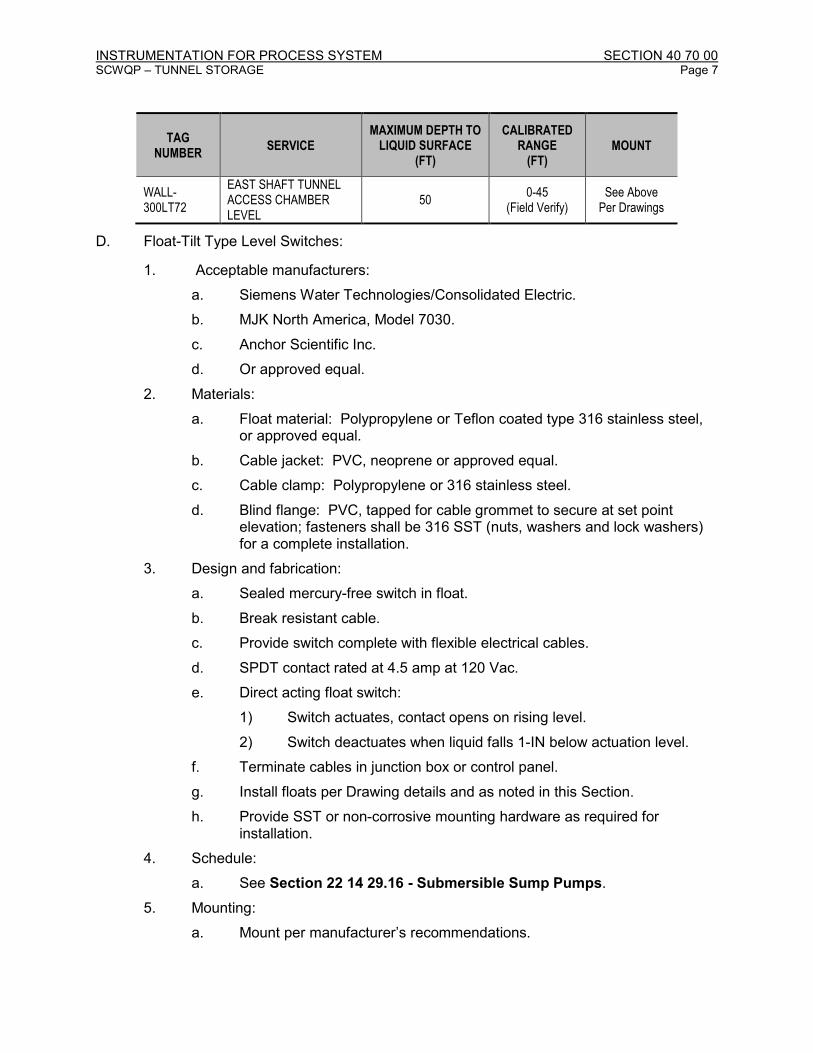
INSTRUMENTATION FOR PROCESS SYSTEM SECTION 40 70 00 SCWQP – TUNNEL STORAGE Page 7
TAG NUMBER
SERVICE MAXIMUM DEPTH TO
LIQUID SURFACE (FT)
CALIBRATED RANGE
(FT) MOUNT
WALL-300LT72
EAST SHAFT TUNNEL ACCESS CHAMBER LEVEL
50 0-45
(Field Verify) See Above
Per Drawings
D. Float-Tilt Type Level Switches:
1. Acceptable manufacturers:
a. Siemens Water Technologies/Consolidated Electric.
b. MJK North America, Model 7030.
c. Anchor Scientific Inc.
d. Or approved equal.
2. Materials:
a. Float material: Polypropylene or Teflon coated type 316 stainless steel, or approved equal.
b. Cable jacket: PVC, neoprene or approved equal.
c. Cable clamp: Polypropylene or 316 stainless steel.
d. Blind flange: PVC, tapped for cable grommet to secure at set point elevation; fasteners shall be 316 SST (nuts, washers and lock washers) for a complete installation.
3. Design and fabrication:
a. Sealed mercury-free switch in float.
b. Break resistant cable.
c. Provide switch complete with flexible electrical cables.
d. SPDT contact rated at 4.5 amp at 120 Vac.
e. Direct acting float switch:
1) Switch actuates, contact opens on rising level.
2) Switch deactuates when liquid falls 1-IN below actuation level.
f. Terminate cables in junction box or control panel.
g. Install floats per Drawing details and as noted in this Section.
h. Provide SST or non-corrosive mounting hardware as required for installation.
4. Schedule:
a. See Section 22 14 29.16 - Submersible Sump Pumps.
5. Mounting:
a. Mount per manufacturer’s recommendations.

INSTRUMENTATION FOR PROCESS SYSTEM SECTION 40 70 00 SCWQP – TUNNEL STORAGE Page 8
E. Building Flood Level Switches:
1. Acceptable Manufacturers:
a. GEMS LS-270 Series.
b. Or approved equal.
2. Design and Fabrication:
a. Action: A liquid rise of 3/8-inch from rest shall operate the float switch.
b. Reset: Automatic reset when liquid level drops 1/16-inch.
c. Designed for sensing flood conditions as an integral and complete system.
d. Provide NEMA 4X junction box and mounting hardware.
e. Operating Range: -40 to 140 DegF
f. Contacts Rating: 0.50A at 24VDC.
3. Mounting:
a. 1 ½” above finished floor.
4. Schedule:
TAG NUMBER SERVICE CONTACT
NO/NC SET POINT ELEVATION
EBAL-200LSHH46 11TH AVENUE ODOR CONTROL ROOM FLOOD
SPDT (Rising)
EBAL-200LSHH47 11TH AVENUE ELECTRICAL ROOM FLOOD
SPDT (Rising)
FRMT-200LSHH46 FREMONT ODOR CONTROL ROOM FLOOD
SPDT (Rising)
FRMT-200LSHH47 FREMONT ELECTRICAL ROOM FLOOD
SPDT (Rising)
FRMT-300LSHH46 FREMONT DRY WELL FLOOD SPDT (Rising)
WALL-200LSHH46 EAST SHAFT ODOR CONTROL ROOM FLOOD
SPDT (Rising)
F. Flange Mounted Diaphragm Level Transmitter:
1. Acceptable manufacturers:
a. Rosemount 3051L.
b. Or approved equal.
2. Materials:
a. Sensor: Type 316L stainless steel.
b. Electronics housing: Cast 316 stainless steel (ASTM CF-8M).
c. Diaphragm: Type 316L stainless steel.
3. Design and Fabrication:
a. Capacitance type pressure transmitter measuring level.

INSTRUMENTATION FOR PROCESS SYSTEM SECTION 40 70 00 SCWQP – TUNNEL STORAGE Page 9
b. Wetted parts: Type 316 stainless steel.
c. HART standard data communications protocol.
d. Indicator: LCD display.
e. Surface mounting.
f. Process connections: Two 1/2-IN female NPT flange adapters.
g. Accuracy: 0.075 percent of calibrated span.
h. Static pressure rating: 2,000 psi
i. Operating range: sufficient to handle scale shown in schedule below.
j. Loop-powered (2-wire) device with 4-20 mA DC output and 9-32 VDC excitation.
4. Schedule:
TAG NUMBER APPLICATION RANGE (FT) DIAPHRAGM SEAL REQ’D
SNUBBER REQ'D
FRMT-200LIT70 FREMONT WET WELL LEVEL
0-70 No No
FRMT-200LIT71 FREMONT WET WELL LEVEL
0-70 No No
2.03 ANALYTICAL COMPONENTS
A. Combustible and Toxic Gas Detectors:
1. Acceptable manufacturers:
a. MSA:
1) Ultima X5000 Series Gas Monitors:
a) Combustible Gas:
(1) Sensor Type: IR Methane.
(2) Range: 0 – 100%.
b) Hydrogen Sulfide (H2S):
(1) Sensor Type: Electrochemical.
(2) Range: 0 – 50 ppm.
c) Oxygen (O2):
(1) Sensor Type: Electrochemical.
(2) Range: 0-25%.
d) Carbon Monoxide (CO):
(1) Sensor Type: Electrochemical.
(2) Range: 0-100 ppm.
2) Or approved equal.

INSTRUMENTATION FOR PROCESS SYSTEM SECTION 40 70 00 SCWQP – TUNNEL STORAGE Page 10
2. Sensor/Transmitter Requirements:
a. Infrared Combustible (IR) Sensor/Transmitters:
1) Capable of calibration without gas. Capable of performing a full calibration by zero adjustment only.
2) Shall detect for an above 100% LEL condition (over-range). This condition must be indicated on the front panel LCD.
3) The IR sensor/transmitter shall not contain a flashback arrestor.
4) Gas check without alternate calibration or gas check fittings or cap.
b. Electrochemical (Toxic) Sensors/Transmitters:
1) Shall not require the periodic addition of reagents.
2) The interconnect wiring from the electrochemical transmitter to the sensor shall be RS-485.
c. Operating Requirements:
1) Temperature range: 32 to 158 DegF.
2) Relative humidity range: 0-95 percent non-condensing.
3) Operating Voltage: 7-30 VDC.
4) Sensor/transmitter wiring configurations: RS-485.
5) Set-up and start-up of the sensor/transmitter shall be so that the enclosure need not be opened during this process.
6) Sensor/transmitter shall contain no pots, jumpers or switches.
7) Transmitter output signal: 4 to 20mA/HART capable of operating into a 600-ohm load.
8) Sensor/transmitter shall allow for full range scaling of the 4-20mA-output signal.
9) Sensor/transmitter shall be capable of storing and displaying average, minimum and maximum gas concentrations over selected periods of time.
10) The sensor/transmitter shall give an indication of when sensor is nearing the end of its useful life by means of the front panel LCD. This indication that the sensor is nearing its useful life shall be based on the sensor output. It shall not be based on the time the sensor was in service.
11) The sensor/transmitter units can be located remote from a monitor/readout unit by up to 100 feet via properly gauge wire.
12) Accuracy:
a) Combustible gas detection:
(1) +3 percent LEL to 50 percent full scale.
(2) +5 percent LEL, 50 to 100 percent full scale.

INSTRUMENTATION FOR PROCESS SYSTEM SECTION 40 70 00 SCWQP – TUNNEL STORAGE Page 11
b) Toxic gas detection:
(1) +10 percent full scale or 2 PPM, whichever is greater.
c) Oxygen detection:
(1) + 2 percent full scale or 2 PPM, whichever is greater.
d) Carbon monoxide detection:
(1) +2 percent full scale or 2 PPM, whichever is greater.
13) Minimum detector response time when exposed to 100 percent LEL gas concentration:
a) 10 seconds to 50 percent LEL.
b) 30 seconds to 90 percent LEL.
14) Store calibration data in nonvolatile memory or back up with battery.
15) HART communication.
d. Sensor/Transmitter Display:
1) Local display to indicate the gas type being monitored and the concentration of gas present. The display shall alternate between the gas type (1 second) and gas concentration (5 seconds). The display shall be an integral part of the sensor/transmitter enclosure. The display shall be visible from a minimum of 5 feet and shall be present always and shall not require being turned on or off. This readout shall be three, one-half-inch (3-1/2") digit Liquid Crystal Displays (LCD).
2) Sensor/transmitter display shall indicate all diagnostic check/fault conditions with a scrolling message detailing the condition. Error codes shall not be used.
3) Sensor/transmitter shall display 3 levels of alarm. Alarm levels shall be adjustable by means of a hand held infrared controller or a HART communicator.
4) Transmitter Display mounting height to be approximately 5 feet above the finished floor.
e. Smart Sensor Technology:
1) Sensors shall be contained in sensor modules mounted external to the main enclosure. All sensor modules shall have the capability of replacement while the unit is under power (hazardous areas) without the need for tools.
2) Sensor modules shall contain all relevant sensor information within the module. This information shall include sensor manufacturer date, gas type, gas range, calibration data, and default relay parameters.

INSTRUMENTATION FOR PROCESS SYSTEM SECTION 40 70 00 SCWQP – TUNNEL STORAGE Page 12
3) Sensor module shall store all calibration data so that the module may be calibrated off site and installed in the field without the necessity of re-calibration. The sensor module shall not require a battery or power source to store this data.
f. Transmitter LED’s and Relays:
1) Sensor/transmitter shall have optional LED’s, viewable from 50 feet, minimum. The LED’s shall operate as follows:
a) Solid green LED – normal operation (measure mode).
b) Solid red LED – fault condition.
c) Blinking red LED – alarm condition.
2) Sensor/transmitter shall have four SPDT relays. Relays shall be rated 5 amps at 30 VDC and consist of three for alarm levels and one for fault. All relay contact activation shall be monitored. If the relay cannot activate for any reason, the trouble relay shall change state. All relays shall be field selectable through a non-intrusive hand-held wireless remote-control unit (Controller) or a HART communicator. Selectable features include:
a) Alarm level.
b) Latching / Non-latching.
c) Upscale / Downscale.
d) Normally-opened / Normally-closed.
e) Energized / De-energized.
3) Relay contacts shall be normally energized (normally closed); contacts shall open in the event of an instrument fault condition.
g. Non-Intrusive Calibration:
1) All sensor/transmitters can be calibrated without opening any enclosures.
2) By means of a non-intrusive hand held wireless remote-control unit or a HART communicator, the sensor/transmitter shall enter the calibration mode. The display of the sensor/transmitter shall instruct the user on when to apply zero and span gas. The sensor/transmitter shall automatically adjust its internal settings to the proper calibration values without further intervention by the user. Upon completion of a successful calibration, the sensor transmitter shall exit the calibration mode. Date stamp of last successful calibration shall be retained in the sensor/transmitter internal memory, with capability to be displayed on LCD. If calibration is unsuccessful for any reason, the display must show an unsuccessful calibration attempt and revert to its previous calibration settings. Use of flashlight type devices, magnets or clamp-on devices to achieve calibration is not acceptable. The acceptable method uses a transmitter, which employs a digitally encoded infrared light beam or a HART communicator.

INSTRUMENTATION FOR PROCESS SYSTEM SECTION 40 70 00 SCWQP – TUNNEL STORAGE Page 13
3) A non-intrusive hand held wireless remote control shall let the user not only do the functions of the small remote control but activate all functions and features of the sensor/transmitter.
4) The sensor/transmitter shall not be affected by low level ambient light either natural or man-made.
h. Sensor replacement:
1) Sensors shall be replaceable without the need to power off sensor/transmitter assembly.
3. Sensor Enclosure and Mounting:
a. Enclosure:
1) The sensor/transmitter shall be in a 316 stainless steel enclosure suitable for location in Class I, Division 1, Groups B, C & D classified areas.
2) The enclosure shall have a minimum of four entries, allowing for flexible mounting options for sensor, power, signal, and optional relay wiring.
3) The enclosure shall offer a means to mount without using an entryway.
b. Mounting:
1) Sensor/transmitter shall be mounted in a single condulet. The back portion of the enclosure shall be separate from the electronics, allowing for mounting and wiring of the unit without the electronics present.
2) A mounting strap shall be used which mounts the sensor/transmitter to a wall or similar structure.
3) The mounting strap shall attach to the sensor/transmitter via two tapped and threaded holes on the rear of the sensor/transmitter. There shall be no brackets or clamps to secure this strap to the sensor/transmitter.
4) Sensor mounting height shall be based on the sensor type:
a) Combustible Gas (LEL) Sensor: 54 inches above finished floor.
b) Hydrogen Sulfide (H2S) Sensor: 18 inches to 24 inches above finished floor.
c) Oxygen (O2) Sensor: 54 inches above finished floor.
d) Carbon monoxide (CO) sensor: 54 inches above finished floor.
c. Remote Sensor Mounting:
1) The sensor portion of the sensor/transmitter unit shall be capable of being able to be remotely mounted from the electronics and display. The separate sensor enclosure shall be able to be mounted up to one hundred (100) feet from the main enclosure.

INSTRUMENTATION FOR PROCESS SYSTEM SECTION 40 70 00 SCWQP – TUNNEL STORAGE Page 14
The sensor housing for the explosion-proof Gas Monitor shall be in an enclosure suitable for location in Class I, Division 1, Groups A, B, C & D classified areas.
2) A two twisted pair cable shall connect the sensor housing and the calibration electronics.
3) The readout portion of the sensor/transmitter shall have a display of the concentration of gas present.
d. Dual Sensor Mounting:
1) For room gas monitors, provide dual sensor transmitters to allow a single transmitter to monitor two gases as shown on the Drawing and in the Instrument Schedule. Install sensors per manufacturer’s recommendations.
2) Dual sensor transmitter shall have two 4-20 mA analog outputs for each gas type monitored, two alarm outputs (one for each type of gas), and one instrument fault alarm output.
4. Approvals: UL Class I, Division 1, Groups A, B, C, and D.
5. Accessories and Ancillary Equipment:
a. Calibration Gas Kit:
1) Calibration kits shall be furnished complete with all tubing, regulators, fittings, communication devices, and accessories required to calibrate sensors.
2) Calibration kit shall utilize non-intrusive means of calibrating sensors/transmitters.
3) Provide two (2) full cylinders of each type of calibration check gas:
a) Cylinder size: 17 liters.
4) Provide the same quantity of zero air cylinders as the total required number of calibration check gas cylinders (of all types).
b. Wireless Controller and HART communicator:
1) A non-intrusive hand held wireless remote control shall let the user not only do the functions of the small remote control but activate all functions and features of the sensor/transmitter.
2) Provide one wireless controller for the project.
c. Ultima X5000 Sampling Module - Sample Pump:
1) SM5000 DC style sampling pump, 12-24 VDC, or approved equal.
2) Draws a gas sample from a monitored area through a sample line to the Ultima X5000 Gas Monitor sensor.
3) Samples from a remote or inaccessible area such as ducts carrying combustible or toxic gas.
4) When using Ultima XCell Gas Monitor, locate the sensor on the exhaust side of the sample module to ensure the most accurate

INSTRUMENTATION FOR PROCESS SYSTEM SECTION 40 70 00 SCWQP – TUNNEL STORAGE Page 15
readings. (The three-way valve from the XIR flow cap must be installed on the inlet side of the pump).
5) Performance Specifications for the Ultima X5000 Sampling Module – Pump Model:
a) Maximum Power Consumption: 8.5 watts at 9 to 30 VDC.
b) Cable Requirements: Four conductor, shielded, 18 AWG (typical).
c) Sample Transport Time: 30 seconds at 0.5 LPM with 50 feet (15.25 meters) of 180 ID sample tubing.
d) Nominal Sample Flow Rate: 2 CFH (1 LPM)
e) Maximum Sample Tubing Length: 100 feet (30 meters).
f) Maximum Exhaust Tubing Length: 20 feet (6 meters)
g) Inlet Fitting: 1/4” (6.35 mm) OD Tubing Fitting.
h) Exhaust Fitting: 1/4” (6.35 mm) OD Tubing Fitting.
i) Calibration Fitting: 1/4” (6.35 mm) OD Barbed Fitting.
j) Overall Dimensions: 9" x 6" x 5" (228.5 cm x 152.4 cm x 127 cm).
k) Weight: 4.5 lbs. (2 kg).
l) Rating: Explosion-proof enclosure, Class I, Groups A, B, C and D, Division 1, Hazardous Locations.
m) Electrical Entry: 3/4-IN-14 NPT.
n) Flow Fail Relay: SPDT at .06 Amps, 125 Volts AC or 110 Volts DC at 2.0 Amps, 30 Volts DC.
o) Temperature Range: -20° to 55°C (-4 to 122°F).
p) Humidity: 15 to 95% RH, Non-condensing.
d. Flow Caps:
1) Designed to force sample gas past sensor head when sample pump is used.
e. Filters:
1) Use with sample pumps.
2) Flow sequence for H2S: high capacity particulate and hydrophobic in-line filter, sensor, sample pump.
3) Flow sequence for LEL: high capacity particulate and hydrophobic in-line filter, sample pump, sensor.

INSTRUMENTATION FOR PROCESS SYSTEM SECTION 40 70 00 SCWQP – TUNNEL STORAGE Page 16
6. Sensing Element Warranty:
a. All sensing elements (sensors) shall have a minimum useful life of one year. The supplier shall provide replacement sensors at no charge for any sensor that does not meet the minimum requirement.
7. Schedule:
TAG NO APPLICATION GAS RANGE SETPOINT
ALARM
EBAL-200AE81A EBAL-200AIT81AB
11TH AVE ODOR CONTROL ROOM
LEL 0-100% 10% LEL
EBAL-200AE81B EBAL-200AIT81AB
11TH AVE ODOR CONTROL ROOM
H2S 0-50 ppm 15 ppm
EBAL-200AE81C EBAL-200AIT81CD
11TH AVE ODOR CONTROL ROOM
OXYGEN 0-25% 19%
EBAL-200AE81D EBAL-200AIT81CD
11TH AVE ODOR CONTROL ROOM
CARBON MONOXIDE
0-100 ppm 10 ppm
EBAL-200AE82A EBAL-200AIT82AB
11TH AVE ELECTRICAL ROOM
LEL 0-100% 10% LEL
EBAL-200AE82B EBAL-200AIT82AB
11TH AVE ELECTRICAL ROOM
H2S 0-50 ppm 15 ppm
EBAL-200AE82C EBAL-200AIT82CD
11TH AVE ELECTRICAL ROOM
OXYGEN 0-25% 19%
EBAL-200AE82D EBAL-200AIT82CD
11TH AVE ELECTRICAL ROOM
CARBON MONOXIDE
0-100 ppm 10 ppm
EBAL-200AE83A EBAL-200AIT83AB
11TH AVE MECHANICAL/ELECTRICAL VAULT ENTRYWAY
LEL 0-100% 10% LEL
EBAL-200AE83B EBAL-200AIT83AB
11TH AVE MECHANICAL/ELECTRICAL VAULT ENTRYWAY
H2S 0-50 ppm 15 ppm
EBAL-200AE83C EBAL-200AIT83CD
11TH AVE MECHANICAL/ELECTRICAL VAULT ENTRYWAY
OXYGEN 0-25% 19%
EBAL-200AE83D EBAL-200AIT83CD
11TH AVE MECHANICAL/ELECTRICAL VAULT ENTRYWAY
CARBON MONOXIDE
0-100 ppm 10 ppm
EBAL-200AE84 EBAL-200AIT84
11TH AVE ODOR CONTROL LEL 0-100% 10% LEL
EBAL-200P84 SAMPLE PUMP FOR EBAL-200AIT*84
--- --- FIELD VERIFY*
EBAL-200AE85 EBAL-200AIT85
11TH AVE ODOR CONTROL H2S 0-50 ppm 15 ppm
EBAL-200P85 SAMPLE PUMP FOR EBAL-200AIT*85
--- --- FIELD VERIFY*
FRMT-200AE81A FRMT-200AIT81AB
FREMONT ODOR CONTROL ROOM
LEL 0-100% 10% LEL
FRMT-200AE81B FRMT-200AIT81AB
FREMONT ODOR CONTROL ROOM
H2S 0-50 ppm 15 ppm
FRMT-200AE81C FRMT-200AIT81CD
FREMONT ODOR CONTROL ROOM
OXYGEN 0-25% 19%
FRMT-200AE81D FRMT-200AIT81CD
FREMONT ODOR CONTROL ROOM
CARBON MONOXIDE
0-100 ppm 10 ppm

INSTRUMENTATION FOR PROCESS SYSTEM SECTION 40 70 00 SCWQP – TUNNEL STORAGE Page 17
TAG NO APPLICATION GAS RANGE SETPOINT
ALARM
FRMT-200AE82A FRMT-200AIT82AB
FREMONT ELECTRICAL ROOM
LEL 0-100% 10% LEL
FRMT-200AE82B FRMT-200AIT82AB
FREMONT ELECTRICAL ROOM
H2S 0-50 ppm 15 ppm
FRMT-200AE82C FRMT-200AIT82CD
FREMONT ELECTRICAL ROOM
OXYGEN 0-25% 19%
FRMT-200AE82D FRMT-200AIT82CD
FREMONT ELECTRICAL ROOM
CARBON MONOXIDE
0-100 ppm 10 ppm
FRMT-200AE83A FRMT-200AIT83AB
FREMONT MECHANICAL/ELECTRICAL VAULT ENTRYWAY
LEL 0-100% 10% LEL
FRMT-200AE83B FRMT-200AIT83AB
FREMONT MECHANICAL/ELECTRICAL VAULT ENTRYWAY
H2S 0-50 ppm 15 ppm
FRMT-200AE83C FRMT-200AIT83CD
FREMONT MECHANICAL/ELECTRICAL VAULT ENTRYWAY
OXYGEN 0-25% 19%
FRMT-200AE83D FRMT-200AIT83CD
FREMONT MECHANICAL/ELECTRICAL VAULT ENTRYWAY
CARBON MONOXIDE
0-100 ppm 10 ppm
FRMT-200AE84 FRMT-200AIT84
FREMONT ODOR CONTROL LEL 0-100% 10% LEL
FRMT-200P84 SAMPLE PUMP FOR FRMT-200AIT*84
--- --- FIELD VERIFY*
FRMT-200AE85 FRMT-200AIT85
FREMONT ODOR CONTROL H2S 0-50 ppm 15 ppm
FRMT-200P85 SAMPLE PUMP FOR FRMT-200AIT*85
--- --- FIELD VERIFY*
FRMT-300AE86A FRMT-300AIT86A
FREMONT DRY WELL @ EL -5.00
LEL 0-100% 10% LEL
FRMT-300P86A SAMPLE PUMP FOR FRMT-300AE**86A
--- --- FIELD VERIFY*
FRMT-300AE86B FRMT-300AIT86B
FREMONT DRY WELL @ EL -48.00
H2S 0-50 ppm 15 ppm
FRMT-300AE86C FRMT-300AIT86CD
FREMONT DRY WELL @ EL -5.00
OXYGEN 0-25% 19%
FRMT-300AE86D FRMT-300AIT86CD
FREMONT DROP STRUCTURE DRY WELL @ EL -5.00
CARBON MONOXIDE
0-100 ppm 10 ppm
FRMT-300AE86E FRMT-300AIT86EF
FREMONT DRY WELL @ EL -48.00
OXYGEN 0-25% 19%
FRMT-300AE86F FRMT-300AIT86EF
FREMONT DRY WELL @ EL -48.00
CARBON MONOXIDE
0-100 ppm 10 ppm
WALL-200AE81A WALL-200AIT81AB
EAST SHAFT ODOR CONTROL ROOM
LEL 0-100% 10% LEL
WALL-200AE81B WALL-200AIT81AB
EAST SHAFT ODOR CONTROL ROOM
H2S 0-50 ppm 15 ppm
WALL-200AE81C WALL-200AIT81CD
EAST SHAFT ODOR CONTROL ROOM
OXYGEN 0-25% 19%
WALL-200AE81D WALL-200AIT81CD
EAST SHAFT ODOR CONTROL ROOM
CARBON MONOXIDE
0-100 ppm 10 ppm

INSTRUMENTATION FOR PROCESS SYSTEM SECTION 40 70 00 SCWQP – TUNNEL STORAGE Page 18
TAG NO APPLICATION GAS RANGE SETPOINT
ALARM
WALL-200AE84 WALL-200AIT84
EAST SHAFT ODOR CONTROL
LEL 0-100% 10% LEL
WALL-200P84 SAMPLE PUMP FOR WALL-200AIT*84
--- --- FIELD VERIFY*
WALL-200AE85 WALL-200AIT85
EAST SHAFT ODOR CONTROL
H2S 0-50 ppm 15 ppm
WALL-200P85 SAMPLE PUMP FOR WALL-200AIT*85
--- --- FIELD VERIFY*
* Field verify the loss of flow setpoint alarm.
B. Duct Smoke Detectors:
1. Provided as accessories to duct system under Section 23 09 13.23 - Sensors and Transmitters.
C. Photoelectric Smoke Detectors:
1. Acceptable manufacturers:
a. Gentex Corporation 8000 Series.
b. Or approved equal.
2. Design and fabrication:
a. Rate of rise photoelectric system.
b. Auto resetting.
c. Four wire head with terminal base models (packaged together).
d. Self-diagnostic capability continually monitors operation.
e. Built-in drift compensation.
f. Field replaceable optical chamber.
g. Low-profile design.
h. Integral heat detectors.
i. Meets NFPA 72 field sensitivity testing without the need for external meters.
j. Input power: 24 VDC.
k. UL listed.
l. Two auxiliary relays, contacts rated at 2A@30VDC.
m. Relay contacts shall be normally energized (normally closed); contacts shall open in the event of an alarm condition.
3. Accessories:
a. Provide Smoke in a CAN (aerosol spray) for functional testing.
4. Schedule:

INSTRUMENTATION FOR PROCESS SYSTEM SECTION 40 70 00 SCWQP – TUNNEL STORAGE Page 19
TAG NUMBER APPLICATION LOCATION
EBAL-200SD81 SMOKE DETECTOR 11TH AVENUE ODOR CONTROL ROOM
EBAL-200SD82 SMOKE DETECTOR 11TH AVENUE ELECTRICAL ROOM
FRMT-200SD81 SMOKE DETECTOR FREMONT ODOR CONTROL ROOM
FRMT-200SD82 SMOKE DETECTOR FREMONT ELECTRICAL ROOM
WALL-200SD81 SMOKE DETECTOR EAST SHAFT ODOR CONTROL ROOM
WALL-200SD82 SMOKE DETECTOR EAST SHAFT ELECTRICAL ROOM
2.04 PRESSURE COMPONENTS
A. Pressure Gage:
1. Acceptable manufacturers:
a. Ashcroft.
b. Ametek.
c. Robert Shaw Acragage.
2. Materials:
a. Element: 316 stainless steel.
b. Case: Phenolic or phenol plastic, unless otherwise noted.
c. Diaphragm seal housing: 316 stainless steel.
d. Pressure snubber:
1) Filter disc: 316 stainless steel.
2) Housing: 316 stainless steel.
3. Accessories:
a. Provide valve at point of connection to equipment and at panel if panel mounted.
b. Utilize pressure snubbers with porous metal discs to provide pulsation dampening on gage applications as shown on schedule.
c. Provide 1/2-IN stainless steel anti-siphon pigtail inlet connection for hot water and steam applications.
4. Design and fabrication:
a. Element type:
1) Direct reading bellows for ranges below 10 psig or compound gauges.
2) Bourdon tube actuated for ranges 10 psig and above.
b. Movement: stainless steel, rotary geared.
c. Range: as noted. Compound scale when noted.

INSTRUMENTATION FOR PROCESS SYSTEM SECTION 40 70 00 SCWQP – TUNNEL STORAGE Page 20
d. Accuracy: plus or minus 1.6 percent of span.
e. Mounting: Lower stem, unless otherwise noted.
f. Dial: 4.5-IN diameter.
g. Pointer: Micrometer pointer with self-locking adjustment.
h. Dampening: Pulsation dampener for all pump or blower discharge applications, and as shown in the schedule.
i. Process Connection: 1/4-IN NPT, unless otherwise noted.
j. Calibrate gages at jobsite for pressure and temperature in accordance with manufacturer's instructions.
k. Unless otherwise required by codes, provide stem mounted or flush mounted, as required, with 4.5-IN diameter dial.
l. Equip with white faces, black numerals and black pointers.
m. Gage tapping position to be clear of equipment functions and movements, and protected from maintenance and operation of equipment:
1) Gage to be readable from an accessible standing position.
n. Gage accuracy: 1 percent of full range.
o. Select gage range so that:
1) The normal operating value is in the middle third of the dial.
2) Maximum operating pressure does not exceed 75 percent of the full-scale range.
p. Certified by the manufacturer for use on natural gas or other potentially explosive gases. (For Odor Control Fan only.)
5. Schedule:
TAG NUMBER
APPLICATION RANGE
(PSI) DIAPHRAGM SEAL REQ’D
SNUBBER REQ'D
FRMT-300PI01
SIPHON DEWATERING PUMP 1 DISCHARGE PRESSURE
0 – 60 psi
No Yes
FRMT-300PI02
SIPHON DEWATERING PUMP 2 DISCHARGE PRESSURE
0 – 60 psi
No Yes
B. Differential Pressure Indicator:
1. Acceptable manufacturers:
a. Mid-West Instruments.
b. Ashcroft.
c. Or approved equal.
2. Materials:
a. Case: die cast aluminum.
b. Diaphragm: silicone rubber.
c. Clear plastic face.

INSTRUMENTATION FOR PROCESS SYSTEM SECTION 40 70 00 SCWQP – TUNNEL STORAGE Page 21
3. Design and Fabrication:
a. Display of differential pressure across an HIGH and LOW process port.
b. Indicator: 4-IN Dial with red tipped pointer.
c. Surface mounting.
d. Process connections: 1/8-IN NPT.
e. Accuracy: 2 percent of full scale.
f. Zero adjustment screw.
g. Certified by the manufacturer for use on natural gas or other potentially explosive gases.
4. Schedule:
TAG NUMBER
APPLICATION RANGE
(PSI) DIAPHRAGM SEAL REQ’D
SNUBBER REQ'D
EBAL-200PDI52A*
11TH AVE ODOR CONTROL VESSEL COMPARTMENT 1 DIFFERENTIAL PRESSURE
See Section 43 41 45.16
No No
EBAL-200PDI52B*
11TH AVE ODOR CONTROL VESSEL COMPARTMENT 2 DIFFERENTIAL PRESSURE
See Section 43 41 45.16
No No
EBAL-200PDI51*
11TH AVE MIST/GREASE ELIMINATOR DIFFERENTIAL PRESSURE
See Section 44 31 14
No No
FRMT-200PDI53*
FREMONT ODOR CONTROL FAN DIFFERENTIAL PRESSURE
See Section 23 34 16.16
No Yes
FRMT-200PDI52A*
FREMONT ODOR CONTROL VESSEL COMPARTMENT 1 DIFFERENTIAL PRESSURE
See Section 43 41 45.16
No No
FRMT-200PDI52B*
FREMONT ODOR CONTROL VESSEL COMPARTMENT 2 DIFFERENTIAL PRESSURE
See Section 43 41 45.16
No No
FRMT-200PDI51*
FREMONT MIST/GREASE ELIMINATOR DIFFERENTIAL PRESSURE
See Section 44 31 14
No No
WALL-200PDI52A*
EAST SHAFT ODOR CONTROL VESSEL COMPARTMENT 1 DIFFERENTIAL PRESSURE
See Section 43 41 45.16
No No
WALL-200PDI52B*
EAST SHAFT ODOR CONTROL VESSEL COMPARTMENT 2 DIFFERENTIAL PRESSURE
See Section 43 41 45.16
No No
WALL-200PDI51*
EAST SHAFT MIST/GREASE ELIMINATOR DIFFERENTIAL PRESSURE
See Section 44 31 14
No No
* Part of vendor package. See specification section listed under “Range” column.
2.05 FLOW COMPONENTS
A. Magnetic Flow Meter:
1. Acceptable manufacturers:
a. Toshiba, Mount Anywhere

INSTRUMENTATION FOR PROCESS SYSTEM SECTION 40 70 00 SCWQP – TUNNEL STORAGE Page 22
b. Or approved equal.
2. General:
a. Flow Meter to consist of a flow tube with separate or integral converter / indicating transmitter, as scheduled. System shall have no moving parts.
b. UL/FM listed: Class I, Division 2.
c. Meter must require minimal strait run for accuracy specified; one diameter upstream and zero diameter downstream.
3. Sensing Element:
a. Flow tubes manufacturer shall provide grounding rings fabricated from the same metal as for the electrodes below.
b. Electrodes shall be 316L stainless steel.
c. Liner shall be hard rubber or polyurethane.
d. Flow tube shall be IP68 and NEMA 6P submersible type.
e. Flange mounted connection using standard ASME B16.5 class 150 flange (18” meter) or AWWA class D flange (42” meter).
f. Fluid conductivity: 5 µS/cm minimum.
g. Fluid temperature: 14 to 140 deg F.
h. Ambient temperature: 14 to 140 deg F.
4. Sensor Connecting Cable:
a. Provide signal cable between the flow tube and transmitter provided by the system manufacturer with sufficient length of cable for continuous installation between the flow tube and the transmitter.
5. Transmitter:
a. Flow measurement accuracy shall be <0.5% of flow rate.
b. Analog signal: 4-20mA current output proportional to process flow rate.
c. Communications output: standard HART protocol.
d. Transmitter shall be 24 VDC powered with surge protection in the power supply.
e. Transmitter shall have optional intrinsically safe barriers factory installed.
f. The transmitter shall have means to calibrate the metering system without use of external calibration units, self-diagnostics and certificate of actual flow lab certification provided with each flow tube.
g. Integral 4-digit LCD flow indication calibrated in process units. Data retained in non-volatile memory.
6. Provide one of each size pipe spool of same diameter, length, and fittings as flow meters.
7. Schedule:

INSTRUMENTATION FOR PROCESS SYSTEM SECTION 40 70 00 SCWQP – TUNNEL STORAGE Page 23
TAG NUMBER SERVICE RANGE (GPM)
METER SIZE (IN)
FRMT-300FE88 FRMT-300FIT88
3RD AVE SIPHON FLOW (LOCATED AT FREMONT DRY WELL)
0 - 12000 18”
FRMT-300FE89 FRMT-300FIT89
3RD AVE FLOW (LOCATED AT FREMONT DRY WELL)
0 - 70000 42”
B. Thermal Dispersion Type Flow Switches:
1. Acceptable manufacturers and models:
a. Ameritrol Inc. FX Series.
b. Or approved equal.
2. Materials:
a. Wetted surfaces: 316 stainless steel.
b. Housing: NEMA 4X; Powder Coated Explosion Proof.
3. Design and fabrication:
a. Repeatability: 0/5% of maximum flow rating at Constant Conditions.
b. Response time:
1) No Flow to Flow: From 3 seconds.
2) Flow to No Flow: From 8 seconds.
c. Operating temperature: -50° to 150°F (-46° to 65°C).
d. Operating Pressure: Full vacuum to 4000 psig (675 bar).
e. Process connection: ¾” MNPT. Other options available.
f. Insertion length: 1.8” standard, other lengths available. For ducts, provide sufficient insertion length to reach center of air duct being measured.
g. Power Input: 24 VDC.
h. Relay output: SPDT 3 amps @ 250 VAC.
i. Conduit entry: 1” FNPT.
j. Approval: UL/CSA Explosionproof.
4. Accessories:
a. Provide hand held calibrator Model MC-5.
5. Schedule:
TAG NUMBER
APPLICATION FLUID
PIPE DIAMETER OR
DUCT SIZE (INCHES)
LOW FLOW SETPOINT

INSTRUMENTATION FOR PROCESS SYSTEM SECTION 40 70 00 SCWQP – TUNNEL STORAGE Page 24
TAG NUMBER
APPLICATION FLUID
PIPE DIAMETER OR
DUCT SIZE (INCHES)
LOW FLOW SETPOINT
EBAL-200FSL81
11TH AVENUE MECHANICAL/ELECTRICAL VAULT SUPPLY FAN
AIR 26 950 cfm
EBAL-200FSL82
11TH AVENUE MECHANICAL/ELECTRICAL VAULT EXHAUST FAN
AIR 24 x 22 900 cfm
FRMT-200FSL53
FREMONT ODOR CONTROL FAN FOUL AIR 30 2000 cfm
FRMT-200FSL81
FREMONT MECHANICAL/ELECTRICAL VAULT SUPPLY FAN
AIR 16 x 20 900 cfm
FRMT-200FSL82
FREMONT MECHANICAL/ELECTRICAL VAULT EXHAUST FAN
AIR 26 800 cfm
FRMT-300FSL31
FREMONT DRY WELL SUPPLY FAN
AIR 20 x 22 650 cfm
FRMT-300FSL32
FREMONT DRY WELL EXHAUST FAN
AIR 20 650 cfm
WALL-200FSL81
EAST SHAFT ODOR CONTROL ROOM SUPPLY FAN
AIR 16 x 16 350 cfm
WALL-200FSL82
EAST SHAFT ODOR CONTROL ROOM EXHAUST FAN
AIR 16 x 16 300 cfm
2.06 INTRUSION SWITCHES
A. Magnetic Reed Switch:
1. Acceptable manufacturers and models:
a. GE Industrial Wide Gap Surface Mount 2500 Series DPDT Model 2507AD.
b. Or approved equal.
2. Hermetically sealed reed switch for installation on metal doors and access hatches for intrusion alarm detection.
3. Switch shall consist of industrial wide gap magnetic contacts surface mounted on doors or hatches.
4. Contact: Aluminum housing armored cable contact, Form C, DPDT, 30Vdc, 0.25A, 3.0W maximum.
5. Schedule:
TAG NUMBER APPLICATION
EBAL-200ZS95 11TH AVENUE MECHANICAL/ELECTRICAL VAULT
FRMT-300ZS94 FREMONT DRY WELL
FRMT-200ZS95 FREMONT MECHANICAL/ELECTRICAL VAULT
NQAN-120ZS79A 3RD AVENUE SLIDE GATE ACTUATOR ENCLOSURE

INSTRUMENTATION FOR PROCESS SYSTEM SECTION 40 70 00 SCWQP – TUNNEL STORAGE Page 25
TAG NUMBER APPLICATION
NQAN-120ZS79B 3RD AVENUE SLIDE GATE ACTUATOR ENCLOSURE
WALL-200ZS82A EAST SHAFT ELECTRICAL BUILDING
WALL-200ZS82B EAST SHAFT ELECTRICAL BUILDING
WALL-300ZS93 EAST SHAFT TUNNEL ACCESS CHAMBER
WALL-200ZS95 EAST SHAFT ODOR CONTROL ROOM
2.07 ACCESSORIES
A. Furnish all mounting brackets, expansion rings, hardware and appurtenances required for mounting primary elements and transmitters:
1. Materials, unless otherwise specified, shall be as follows:
a. Bolts, nuts, washers, expansion anchors: 316 stainless steel.
b. Mounting brackets and expansion rings:
1) Standard: 316 stainless steel.
2) Highly corrosive areas: Aluminum.
c. Mounting plates, angles:
1) Standard: Stainless steel.
2) Corrosive areas: 316 stainless steel.
B. Provide handheld communicator compatible with all transmitters furnished:
1. Hand held communicator shall provide capability to check calibration, change transmitter range, and provide diagnostics.
2. If these features are not provided with the transmitter, the hand held communicator is not required.
C. Cable lengths between sensors and transmitters shall be continuous (without splices) and as required to accommodate locations as shown on Drawings and by the installation, no exceptions.
2.08 PIPE, TUBING AND FITTINGS
A. Acceptable Manufacturers:
1. Tube fittings:
a. Parker CPI.
b. Swagelok.
c. Or approved equal.
B. Instrument Tubing and Fittings:
1. Material:
a. Tubing: ASTM A269, Grade TP 316 stainless steel.

INSTRUMENTATION FOR PROCESS SYSTEM SECTION 40 70 00 SCWQP – TUNNEL STORAGE Page 26
b. Straight fittings: 316 stainless steel per ASME SA-479 or ASTM A276.
c. Shaped bodies: ASME SA-182 F316 stainless steel.
2. Design and fabrication:
a. Tubing:
1) Seamless.
2) Fully annealed.
3) Maximum hardness: 80 Rb.
4) Free from surface scratches and imperfections.
5) Diameter: 1/4 IN OD unless specified otherwise.
6) Wall thickness:
a) Meet requirements of ASME B31.1, Paragraph 122.3.
b) Minimum 0.049 IN for 1/2 IN OD tubing.
b. Fittings:
1) Flareless.
2) Compression type.
C. Instrument Piping:
1. For applications where the instrument is supported solely by the sensing line, (e.g., pressure gauge directly mounted to process line) utilize piping as specified below.
a. Diameter: 1/4 IN unless specified otherwise.
b. Schedule 80.
c. 316 stainless steel.
2.09 INSTRUMENT VALVES
A. Process instrument multi-valve manifolds, isolation, vent and blow-down valves:
1. Acceptable manufacturers:
a. Whitey Co.
b. Anderson-Greenwood USA, Inc.
c. Or approved equal.
2. Materials:
a. Packing:
1) 450 DegF and above: Graphite.
2) Below 450 DegF: Graphite or Teflon.
b. Body: 316 stainless steel per ASTM A479.
c. Stem: 316 stainless steel per ASTM A276.

INSTRUMENTATION FOR PROCESS SYSTEM SECTION 40 70 00 SCWQP – TUNNEL STORAGE Page 27
d. Ball: 316 stainless steel per ASTM A276.
e. Support rings: 316 stainless steel per ASTM A276.
f. Seats:
1) Metal:
a) 316 stainless steel per ASTM A276.
2) Soft:
a) Teflon, Delrin.
b) Only utilized on applications where manufacturer's temperature and pressure ratings exceed process design conditions.
3. Design and fabrication:
a. Either of the following:
1) Ball valve with 1/4 turn activation.
2) Free-swiveling ball stem.
b. Provide body wall thickness sufficient for process design conditions per ASME B31.1.
c. Temperature: Manufacturer's temperature rating for all components shall exceed process design conditions.
PART 3 - EXECUTION
3.01 INSTALLATION
A. Install products in accordance with manufacturer's instructions.
B. Install instrument mounting level and plumb.
C. Instrument connections to process lines shall utilize instrument tubing, piping and valves as outlined in this Specification unless otherwise noted in the Contract Documents.
D. Locate instrument so as to be free of vibration and interference with other piping, conduit, or equipment.
E. Keep foreign matter out of the system.
F. Plug all open ends and connections to keep out contaminants.
G. Threaded Connection Seals:
1. Use Tite-Seal or acceptable alternate.
2. Use of lead base pipe dope or Teflon tape is not acceptable.
3. Do not apply Tite-Seal to tubing threads of compression fittings.
H. Instrument Mounting:

INSTRUMENTATION FOR PROCESS SYSTEM SECTION 40 70 00 SCWQP – TUNNEL STORAGE Page 28
1. Mount all instruments where they shall be accessible from fixed ladders, platforms, or grade wherever possible.
2. Mount all local indicating instruments with face forward toward the normal operating or access area, within reading distance, and in the line of sight.
3. Mount instruments level, plumb, and support rigidly.
4. Mount to provide:
a. Protection from heat, shock, and vibrations.
b. Accessibility for maintenance.
c. Freedom from interference with piping, conduit and equipment.
I. Terminal junction boxes for wiring connections to field instruments shall not be permitted to be installed in any wet locations.
J. Cable:
1. Provide 10-feet minimum spare length of neatly coiled cable at both ends (near instrument in the field and in the associated control panel) for each sensor and transmitter.
2. Factory supplied cables shall not be cut to reduce cable lengths.
3.02 TRAINING
A. Provide on-site training in accordance with Section 01 75 00 – Commissioning.
B. In addition to the training requirements in Section 01 75 00 – Commissioning provide training for primary elements, at the minimum, include the following:
1. Transmitter programming and configuration.
2. Calibration.
3. Desiccant maintenance (Submersible Pressure Sensor and Transmitter).
4. Importance of non- kinking sensor cable (Submersible Pressure Sensor and Transmitter).
END OF SECTION 40 70 00

PANEL MOUNTED INSTRUMENTS SECTION 40 78 00 SCWQP – TUNNEL STORAGE Page 1
PART 1 - GENERAL
1.01 SECTION INCLUDES
A. Specification Section Includes:
1. Signal modules:
a. Loop isolator.
2. Alarm Devices:
a. Buzzer (Horn).
b. Strobe.
3. Termination equipment:
a. Terminal blocks.
b. Fuse holders.
4. Power supplies:
a. DC power supplies.
b. DC Uninterruptible Power Supplies.
c. DC to DC power supplies.
5. Voltage surge protection devices.
6. Operator Interface Unit (OIU).
7. Ethernet Switch: Unmanaged.
8. Batteries.
9. Limit switches.
10. Pilot Devices.
11. Pilot Devices: Hazardous Rated.
12. Relays/Timers.
13. Intrinsic Safety Devices.
14. Fiber patch panels.
15. Ethernet to Fiber Media Converters.
1.02 REFERENCE STANDARDS
A. Referenced Standards:
1. The Instrumentation, Systems, and Automation Society (ISA):
a. S18.1, Annunciator Sequences and Specifications.
2. National Electrical Manufacturers Association (NEMA):
a. 250, Enclosures for Electrical Equipment (1000 Volts Maximum).

PANEL MOUNTED INSTRUMENTS SECTION 40 78 00 SCWQP – TUNNEL STORAGE Page 2
b. ICS 2, Industrial Control and Systems: Controllers, Contactors, and Overload Relays Rated 600 Volts.
3. Underwriters Laboratories, Inc. (UL).
1.03 DEFINITIONS
(NOT USED)
1.04 SUBMITTALS
A. Procedures: Section 01 33 10 – Submittals.
B. A copy of this specification section, with addendum updates included, and all referenced and applicable sections, with each paragraph check-marked to indicate compliance or marked to indicate requested deviations.
C. Shop Drawings:
1. See Section 40 61 13 - Process Control System General Provisions.
D. Operation and Maintenance Manuals:
1. See Section 01 78 23 – Operation and Maintenance Data for requirements for:
a. The mechanics and administration of the submittal process.
b. The content of Operation and Maintenance Manuals.
1.05 QUALITY ASSURANCE
A. Miscellaneous:
1. Assure units comply with electrical area classifications and NEMA enclosure type shown on Drawings.
PART 2 - PRODUCTS
2.01 ACCEPTABLE MANUFACTURERS
A. Subject to compliance with the Contract Documents, the manufacturers as listed in the articles describing the devices are acceptable.
B. Provide similar components from the same manufacturer for uniformity of appearance, installation, operations, and maintenance.
C. Submit request for substitution in accordance with Section 01 33 10 – Submittals .
2.02 SIGNAL MODULE
A. Loop Isolators (where required):
1. Acceptable manufacturers:
a. Moore Industries.
b. AGM Electronics.

PANEL MOUNTED INSTRUMENTS SECTION 40 78 00 SCWQP – TUNNEL STORAGE Page 3
c. Or approved equal.
2. Design and fabrication:
a. Solid state electronics.
b. Transmit analog output signal directly proportional to measured input signal.
c. Power source: 24 Vdc.
d. Analog input: 4-20 mA DC.
e. Output signal: 4-20 mA DC into 1400 ohms.
f. Impedance:
1) Voltage input: 10 Meg.
2) Current input: 50 ohms.
3) Voltage output: 1 ohm.
4) Current output: 1650 ohms.
g. Accuracy: Better than ± 0.10 percent of span.
h. Isolation: Up to 500 V rms (input, output and case).
i. Temperature effect: ±0.0025 percent of span per DegF.
j. Ambient temperature range: 0-140 DegF.
k. Factory calibrated.
l. UL listed.
2.03 ALARM DEVICES
A. Buzzers (Horns):
1. Vibrating horn type, Edwards 870EX series or approved equal.
2. PLC compatible as required.
3. Heavy-duty die cast housing with corrosion resistant finish.
4. Adjustable volume: 78 to 103 dB at 10-FT.
5. Voltage: 24Vdc or as required.
6. Suitable for use in Class I Division 1 or Division 2 location.
7. Enclosures/mountings:
a. NEMA 4X.
b. Maintain enclosure rating.
B. Strobes:
1. Flashing Strobe: Edwards 116 series, or approved equal.
2. Strobe / Light:
a. 360-degree beam.

PANEL MOUNTED INSTRUMENTS SECTION 40 78 00 SCWQP – TUNNEL STORAGE Page 4
b. 3 Joule.
3. Approximate flash rate: 60 – 90 flashes per minute.
4. Mounting: base, brackets, fixtures, and hardware as required.
5. Enclosure:
a. NEMA 4X.
b. Maintain enclosure rating.
c. Corrosion resistant.
6. Suitable for use in Class I Division 1 or Division 2 location.
7. Voltage: 24 VDC.
8. UL Listed.
2.04 TERMINATION EQUIPMENT
A. Terminal Blocks:
1. Acceptable manufacturers:
a. Phoenix Contact.
b. Allen-Bradley.
c. Weidmuller.
d. Or approved equal.
2. Design and fabrication:
a. Modular type with screw compression clamp.
b. Captive screws: Stainless steel.
c. Current bar: Nickel-plated copper allow.
d. Thermoplastic insulation rated for -40 to +90 DegC.
e. Wire insertion area: Funnel-shaped to guide all conductor strands into terminal.
f. Install end sections and end stops at each end of terminal strip.
g. Install machine-printed terminal markers on both sides of block.
h. Spacing: 6 mm.
i. Tiers/Levels: as required; 3 maximum.
j. Wire size: 22-12 AWG.
k. Rated voltage: 600 V.
l. DIN rail mounting.
m. UL listed.
3. Standard-type block:
a. Rated current: 30 A.

PANEL MOUNTED INSTRUMENTS SECTION 40 78 00 SCWQP – TUNNEL STORAGE Page 5
b. Color: Gray body.
4. Bladed-type block:
a. Terminal block with knife blade disconnect which connects or isolated the two (2) sides of the block.
b. Rated current: 10 A.
c. Color:
1) Panel control voltage leaves enclosure - normal: Gray body, orange switch.
2) Foreign voltage entering enclosure: Orange body, orange switch.
5. Grounded-type block:
a. Electrically grounded to mounting rail.
b. Use to terminal ground wires and analog cable shields. Use isolated ground bus for analog cable shields.
c. Color: Green and yellow body.
B. Fuse Holders:
1. Acceptable manufacturers:
a. Phoenix Contact.
b. Allen-Bradley.
c. Weidmuller.
d. Or approved equal.
2. Design and fabrication:
a. Modular-type with screw compression clamp.
b. Screws: Stainless steel.
c. Current bar: Nickel-plated copper alloy.
d. Thermoplastic insulation rated for -40 to +105 DegC.
e. Wire insertion area: Funnel-shaped to guide all conductor strands into terminal.
f. Draw out type of fuse holder.
g. Blocks can be ganged for multi-pole operation.
h. Install end sections and end stops at each end of terminal strip.
i. Install machine-printed terminal markers on both sides of block.
j. Spacing: 9.1 mm.
k. Wire size: 30-12 AWG.
l. Rated voltage: 300 V.
m. Rated current: 12 A.
n. Fuse size: 1/4-x 1-1/4.

PANEL MOUNTED INSTRUMENTS SECTION 40 78 00 SCWQP – TUNNEL STORAGE Page 6
o. Blown fuse indication: LED.
p. DIN rail mounting.
q. UL listed.
2.05 POWER SUPPLIES
A. DC Power Supplies:
1. Acceptable manufacturers:
a. PULS, Model CS10.243.
b. No equal.
2. Design and fabrication:
a. Converts 120 Vac input to DC power at 24VDC.
b. Output current: 10A continuous.
c. DIN rail mount with enclosure.
d. UL Listed for use in UL 508 industrial control panels.
e. Filtered and electronically regulated output.
f. Switching type.
g. AC input: 120 Vac +/-15 percent, nominal 60 Hz.
h. Efficiency: Minimum 90 percent.
i. Rated mean time between failure (MTBF): 500,000 HRS.
j. Voltage regulation:
1) Static: Less than 1.0 percent Vout.
2) Dynamic: +/-2 percent Vout overall.
k. Output ripple/noise: Less than 100 mV peak to peak (20 MHz).
l. Overload, short circuit and open circuit protection.
m. Temperature rating: -25 to 60 DegC full rated, derated linearly to 75 percent at 70 DegC.
n. Humidity rating: Up to 90 percent, non-condensing.
o. LED status indication for DC power.
p. Three (3) year warranty.
B. DC Uninterruptible Power Supplies:
1. Acceptable manufacturers:
a. PULS, Model UB10.242.
b. No equal.
2. Design and fabrication:
a. Power supply with built-in charger for gel or lead acid batteries.

PANEL MOUNTED INSTRUMENTS SECTION 40 78 00 SCWQP – TUNNEL STORAGE Page 7
b. Voltage in: 24VDC; voltage out: 24VDC.
c. Battery voltage: 12VDC.
d. Battery Amp-Hour range: 17Ah-130Ah.
e. Output current: 10A continuous.
f. DIN rail mount with enclosure.
g. UL Listed for use in UL 508 industrial control panels.
h. Filtered and electronically regulated output.
i. Rated mean time between failure (MTBF): 500,000 HRS.
j. Temperature rating: -25C to 50C.
k. Overload, short circuit and open circuit protection.
l. LED status indication for the following:
1) Status (i.e. ready, charging or buffering).
2) Diagnosis (i.e. overload, replace battery, or inhibit active).
3) Check wiring.
m. Relay contacts to monitor the following:
1) Ready (i.e. battery charged).
2) Buffering (i.e. on battery power).
3) Replace battery.
n. Three (3) year warranty.
C. DC to DC Power Supplies:
1. Acceptable manufacturers:
a. PULS, Model CD5.121.
b. No equal.
2. Design and fabrication:
a. Current output: 8A.
b. Voltage in: 24V; Voltage out: 12V.
c. Reverse input polarity protection.
d. DIN rail mounting.
e. UL Listed for use in UL 508 industrial control panels.
f. Short-circuit, overload, and over-voltage protection.
g. Built-in EMI filter with low ripple noise.
h. Temperature rating: -25C to 60C.
i. 100% full load burn-in test.
j. Three (3) year warranty.

PANEL MOUNTED INSTRUMENTS SECTION 40 78 00 SCWQP – TUNNEL STORAGE Page 8
2.06 BATTERIES
A. Acceptable manufacturers:
1. Power Sonic PG-12V103FR.
2. Yukasa.
3. Or approved equal.
B. Design and fabrication:
1. Voltage: 12 VDC, nominal.
2. Amp-hours: 100.
3. Characteristics:
a. Rechargeable.
b. Leak-free.
c. Maintenance-free.
4. Technology: Valve-Regulated Lead Acid (VRLA).
5. UL-recognized.
C. Terminations and Interconnect Cabling:
1. As required for complete, functional and code-compliant installation.
D. Mounting:
1. Use shelving to keep batteries from resting directly on cabinet floor.
2. Secure batteries to prevent tipping.
2.07 VOLTAGE SURGE PROTECTION DEVICES
A. See Section 40 78 56 – Isolators, Intrinsically-Safe Barriers, and Surge Suppressors.
2.08 OPERATOR INTERFACE UNIT (OIU):
A. Acceptable manufacturers:
1. For Main Control Panels: Red Lion, Graphite G10S0000 – 10-inch, Color Touchscreen, cables, and Crimson programming software.
2. Or approved equal.
B. Design and fabrication:
1. Input power: 24 VDC.
2. Display:
a. 10-inch: TFT active matrix, SVGA, 16M color, 800 x 600 pixel.
b. Resistive analog touchscreen.
c. 30,000 hour backlight.

PANEL MOUNTED INSTRUMENTS SECTION 40 78 00 SCWQP – TUNNEL STORAGE Page 9
d. NEMA 4/IP 65 rating.
3. Communication ports:
a. Serial: Three (3) total (1-RS-232 (PGM), 1-RS-232 (COMMS), 1-RS-422/485), individually programmable up to 115,200 baud.
b. Individually programmable up to 115,200 baud.
4. Memory:
a. Unit configuration: Stored in non-volatile flash memory.
b. SanDisk® or SimpleTech Compact Flash®, 2 GB, industrial grade, two million write cycles, minimum.
5. Cables:
a. USB to RS-232 serial adaptor cable.
b. Y-cable.
6. Software:
a. Crimson® 3.0, or latest available, SPU-approved version.
b. Or approved equal.
2.09 ETHERNET SWITCH, UNMANAGED
A. Acceptable manufacturers:
1. Wiedmuller, IE-BL08-8TX.
2. Or approved equal.
B. Design and fabrication:
1. Input power: 4VA for AC input, or 4W for DC input.
2. Input voltage: 12-24 VAC, 10-35 VDC.
3. Input frequency: 47 – 63 Hz.
4. Eight (8) each (minimum), RJ45 ports.
5. DIN-mounted.
6. Operating temperature: -0C to 60C.
7. Standard: IEEE 802.3, 3U and 3X.
8. Protection class: IP20.
9. Data rate: 10 Base-T/100 Base-TX (copper); 100 Base-FX (fiber).
10. Functionality: Autonegotiation and Autocrossing (RF45); redundant voltage supply.
11. Status indication: Data rate, Power, Connection/Activity.
12. Approvals: cULus, Class I, Division 2, CD, EN55024, EN 55022, Gost R.
13. Supported protocols: Modbus TCP, TCP/IP, EthernetIP.

PANEL MOUNTED INSTRUMENTS SECTION 40 78 00 SCWQP – TUNNEL STORAGE Page 10
2.10 PILOT DEVICES
A. Selector Switches:
1. Acceptable manufacturers:
a. Allen-Bradley.
b. Square D.
c. Or approved equal.
2. Design and fabrication:
a. Heavy-duty type.
b. Oiltight and NEMA 4X rated.
c. Rotary cam units conforming to NEMA ICS 2-216.22.
d. Mounting hole: 30.5 mm.
e. Supply switches having number of positions required with contact blocks to fulfill functions shown and specified.
f. UL listed.
g. Maintained contact type.
h. Knob type operators.
i. Black colored operators.
j. Designed with cam and contact block with approximate area of 2-IN SQ.
k. Legend plate marked per Contract Documents.
l. Contact block requirements:
1) Dry and indoor locations: Standard contact blocks rated for 10 A continuous current.
2) Wet or outside locations: Hermetically sealed contact blocks.
3) Hazardous location: Hermetically sealed contact blocks rated for Class I, Division 2 locations.
B. Pushbuttons:
1. Acceptable manufacturers:
a. Allen-Bradley.
b. Square D.
c. Or approved equal.
2. Materials:
a. Backing diaphragm: Buna-N.
3. Design and fabrication:
a. Heavy-duty type.
b. Oiltight and NEMA 4X rated.

PANEL MOUNTED INSTRUMENTS SECTION 40 78 00 SCWQP – TUNNEL STORAGE Page 11
c. Conforming to NEMA ICS 2-216.22.
d. Mounting hole: 30.5 mm.
e. Diaphragm backed.
f. UL listed.
g. Emergency stop pushbuttons to have mushroom head operator and maintained contact.
h. Non-illuminated type:
1) Momentary contact with necessary contact blocks.
2) Molded, solid color melamine buttons.
3) Standard flush operators with full shroud.
4) Emergency stop pushbuttons shall have mushroom head operators.
5) Red colored buttons for START or ON and black color for STOP or OFF. Black color for SILENCE.
6) Appropriate contact blocks to fulfill functions shown or specified.
i. Contact block requirements:
1) Dry and indoor locations: Standard contact blocks rated for 10 A continuous current.
2) Wet or outside locations: Hermetically sealed contact blocks.
3) Hazardous location: Hermetically sealed contact blocks rated for Class I, Division 2 locations.
j. Legend plate marked per Contract Documents.
C. Indicating Lights:
1. Acceptable manufacturers:
a. Allen-Bradley.
b. Square D.
c. Or approved equal.
2. Design and fabrication:
a. Push-to-test.
b. Heavy duty type.
c. Oiltight and NEMA 4X rated.
d. Type allowing replacement of bulb without removal from control panel.
e. LED type lamp.
f. UL listed.
g. 24 V lamp.
h. Legends marked per Contract Documents.

PANEL MOUNTED INSTRUMENTS SECTION 40 78 00 SCWQP – TUNNEL STORAGE Page 12
i. Nominal 2-IN SQ face.
j. Mounting hole: 30.5 mm.
k. Glass lens.
l. Color code lights as follows:
1) Green: OFF or stopped; valve closed.
2) Amber: Fault/Trouble/Malfunction.
3) Red: ON or running; valve open.
m. Legend plate engraved for each light.
2.11 RELAYS/TIMERS
A. Control Relays:
1. Acceptable manufacturers:
a. Idec.
b. Potter & Brumsfield.
c. Allen-Bradley.
2. Design and fabrication:
a. Plug-in general purpose relay.
b. Blade connector type.
c. Switching capacity: 10 A.
d. Contact material: Silver cadmium oxide.
e. Provide relays with a minimum of 3 SPDT contacts.
f. Coil voltage: 120 Vac or 24 Vdc.
g. Relay sockets are DIN rail mounted.
h. Internal neon or LED indicator is lit when coil is energized.
i. Clear polycarbonate dust cover with clip fastener.
j. Check button.
k. Temperature rise:
1) Coil: 85 DegF max.
2) Contact: 65 DegF max.
l. Insulation resistance: 100 Meg min.
m. Frequency response: 1800 operations/hour.
n. Operating temperature: -20 to +150 DegF.
o. Life expectancy:
1) Electrical: 500,000 operations or more.
2) Mechanical: 50,000,000 operations or more.

PANEL MOUNTED INSTRUMENTS SECTION 40 78 00 SCWQP – TUNNEL STORAGE Page 13
3. UL listed or recognized.
B. Time Delay Relays:
1. Acceptable manufacturers:
a. Eagle Signal Controls.
b. Idec.
c. Or approved equal.
2. Design and fabrication:
a. Melt design test and performance requirements of NEMA ICS 2-218.
b. Heavy-duty.
c. Solid-state construction.
d. External adjusting dial.
e. Auxiliary relays as required to perform functions specified or shown on Drawings.
f. Operates on 120 Vac or 24 Vdc (±10 percent) power source.
g. Contact rating: A150 per NEMA ICS 2-125.
h. Furnish with "On" and "Timing Out" indicators.
2.12 INTRINSIC SAFETY DEVICES
A. Intrinsic Safety Isolators:
1. Acceptable Manufacturers:
a. Pepperl + Fuchs.
b. No equal.
2. Acceptable Models:
a. Analog signals (2-channel):
1) KFD2-STC4-Ex2.
b. Discrete signals (2-channel):
1) KFD2-SR2-Ex2W.
3. Design and Fabrication:
a. Uses a low-power, electrically isolated to safely interface with devices located in hazardous areas.
b. Provided with green and red LED for indication of module and field circuit status.
c. Interface as required by application.
d. External power: 24 Vdc.
e. Pole reversal protection.
f. Captured, self-opening screw terminals.

PANEL MOUNTED INSTRUMENTS SECTION 40 78 00 SCWQP – TUNNEL STORAGE Page 14
g. Response time: less than 20ms.
h. Galvanic isolation:
1) Input/Output: 1500V.
2) Input/external supply: 1500V.
3) Output/External supply: 500V.
i. Radio interference suppression: Class A.
j. Housing material: polymide.
k. Operating temperature: -20 to +60 DegC.
l. DIN rail mounting.
m. Grounding method: not required.
n. Testing laboratory approvals: FM and UL.
2.13 FIBER PATCH PANEL (SINGLE-PANEL HOUSING)
A. See Section 27 13 23 – Fiber Optic Cable Network General.
2.14 ETHERNET TO FIBER MEDIA CONVERTER:
A. Acceptable manufacturers:
1. Moxa IMC-101.
2. Or approved equal.
B. Design and fabrication:
1. Input current: 160 mA at 24VDC
2. Input voltage: 12-45 VDC.
3. 10/100BaseT(X) RJ45 ports.
4. 100Base FX fiber ports (SC/ST connectors)
5. DIN-mounted.
6. Operating temperature: -0C to 60C.
7. Standard: IEEE 802.3, 3U and 3X.
8. Protection class: IP30.
9. Status indication: Data rate, Power, Connection/Activity.
10. Approvals: cULus, Class I, Division 2, CD, EN55024, EN 55032, RoHS.
PART 3 - EXECUTION
3.01 INSTALLATION
A. Install products in accordance with manufacturer's instructions and SPU standards.
B. Provide as shown on Drawings and as required.

PANEL MOUNTED INSTRUMENTS SECTION 40 78 00 SCWQP – TUNNEL STORAGE Page 15
END OF SECTION 40 78 00

ISOLATORS, INTRINSICALLY-SAFE BARRIERS, AND SURGE SUPPRESSORS SECTION 40 78 56SCWQP – TUNNEL STORAGE Page 1
PART 1 - GENERAL
1.01 SECTION INCLUDES
A. Specification Section Includes:
1. Type IC1 SPD - Dedicated 120 Vac circuit, series connection, control panel mounted.
2. Intrinsic Safety Devices.3. Intrinsic Safety Barriers.
1.02 REFERENCE STANDARDS
A. Referenced Standards:
1. Institute of Electrical and Electronics Engineers, Inc. (IEEE):a. C62.41, Recommended Practice for Surge Voltages in Low-Voltage AC
Power Circuits.2. National Electrical Manufacturers Association (NEMA):
a. 250, Enclosures for Electrical Equipment (1000 Volts Maximum).b. LS 1, Low Voltage Surge Protection Devices.
3. Underwriters Laboratories, Inc. (UL):a. 497B, Standard for Safety Protectors for Data Communications and Fire-
Alarm Circuits.b. 1283, Standard for Safety Electromagnetic Interference Filters.c. 1363, Standard for Safety Relocatable Power Taps.d. 1449, Standard for Safety Transient Voltage Surge Suppressors.
1.03 DEFINITIONS
A. Clamping Voltage: The voltage measured at the end of the 6-IN output leads of the SPD and from the zero-voltage reference to the peak of the surge when the applied surge is induced at the 90-degree phase angle of the applied system frequency voltage.
B. Let-Through Voltage: The voltage measured at the end of the 6-IN output leads of the SPD and from the system peak voltage to the peak of the surge when the applied surge is induced at the 90-degree phase angle of the applied system frequency voltage.
C. Maximum Continuous Operating Voltage (MCOV): The maximum steady state voltage at which the SPD device can operate and meet it specification within its rated temperature.
D. Maximum Surge Current:
1. The maximum 8 x 20 microsecond surge current pulse the SPD device is capable of surviving on a single-impulse basis without suffering either

ISOLATORS, INTRINSICALLY-SAFE BARRIERS, AND SURGE SUPPRESSORS SECTION 40 78 56SCWQP – TUNNEL STORAGE Page 2
performance degradation or more than 10 percent deviation of clamping voltage at a specified surge current.
2. Listed by mode, since number and type of components in any SPD may vary by mode.
E. Protection Modes: This parameter identifies the modes for which the SPD has directly connected protection elements, i.e., line-to-neutral (L-N), line-to-line (L-L), line-to-ground (L-G), neutral-to-ground (N-G).
F. Surge Current per Phase:
1. The per phase rating is the total surge current capacity connected to a given phase conductor.
2. For example, a wye system surge current per phase would equal L-N plus L-G; a delta system surge current per phase would equal L-L plus L-G:a. The N-G mode is not included in the per phase calculation.
G. System Peak Voltage: The electrical equipment supply voltage sine wave peak (i.e., for a 120 V system the L-N peak voltage is 170 V).
1.04 SUBMITTALS
A. Procedures: Section 01 33 10 – Submittals.
B. A copy of this specification section, with addendum updates included, and all referenced and applicable sections, with each paragraph check-marked to indicate compliance or marked to indicate requested deviations.
C. Shop Drawings:
1. For named products, submit only a catalog cut sheet.a. For all other products, submit the data required as specified in Sub-
paragraph 1.04.C.4 of this Section.2. See Section 40 61 13 - Process Control System General Provisions.3. Product technical data for non-specified models:
a. Manufacturer’s experience.b. Standard catalog cut sheet.c. Electrical and mechanical drawing showing unit dimensions, weights,
mounting provisions, connection details and layout diagram of the unit.d. Create a Product Data Sheet for each different model number of SPD
provided:1) Data in the Product Data Sheet heading:
a) SPD Type per PART 2 of this Section.b) Manufacturer’s Name.c) Product model number.
2) Data in the Product Data Sheet body:

ISOLATORS, INTRINSICALLY-SAFE BARRIERS, AND SURGE SUPPRESSORS SECTION 40 78 56SCWQP – TUNNEL STORAGE Page 3
a) Column one: Specified value/feature of every paragraph of PART 2 of this Section.
b) Column two: Manufacturer’s certified value confirming the product meets the specified value/feature.
3) Data in the Product Data Sheet closing:a) Signature of the manufacturer’s official (printed and
signed).b) Title of the official.c) Date of signature.
4. Product data for intrinsic safety barriers. See Section 40 78 00 – Panel Mounted Instruments.
D. Operation and Maintenance Manual:
1. See Section 01 78 23 – Operation and Maintenance Data for requirements for the submittal process.
1.05 QUALITY ASSURANCE
A. Qualifications:
1. Provide devices from a manufacturer who has been regularly engaged in the development, design, testing, listing and manufacturing of SPDs of the types and ratings required for a period of ten (10) years or more and whose products have been in satisfactory use in similar service.
2. Upon request, suppliers or manufacturers shall provide a list of not less than three (3) customer references showing satisfactory operation.
1.06 WARRANTY
A. The manufacturer shall provide a minimum of a five (5) year Limited Warranty from date of shipment against failure when installed in compliance with applicable national/local electrical codes and the manufacturer’s installation, operation and maintenance instructions.
PART 2 - PRODUCTS
2.01 ACCEPTABLE MANUFACTURERS
A. Subject to compliance with the Contract Documents, the manufacturers model numbers listed in the individual product paragraphs below are acceptable.
2.02 TYPE IC1 SPD
A. Approved Products:
1. Cutler Hammer: AGSHW CH-120N-15-XS.2. Phoenix Contact: SFP 1-20/120AC (2856702).

ISOLATORS, INTRINSICALLY-SAFE BARRIERS, AND SURGE SUPPRESSORS SECTION 40 78 56SCWQP – TUNNEL STORAGE Page 4
3. EDCO: HSP121BT-1RU.4. MTL: MA15/D/1/SI.
B. Standards: UL 1449.
C. Design:
1. General:a. Mounted internally to control panels for point-of-use loads.b. MOV based or multi-stage hybrid solid state high performance
suppression system.c. Designed for series connection.d. Enclosure: Metallic or plastic, flange or DIN rail mounting.e. Field connection: Provide unit with external terminal screws for each
phase, neutral and ground that will accept #14 through #12 conductors.f. Device monitoring: Long-life, solid state, externally visible indicators that
monitors the on-line status of the unit’s suppression filter system or power loss in any of the phases.
2. Operating voltage: 120 Vac.3. Operating current: 15 A minimum.4. Operating frequency: 45 to 65 Hz.5. Modes of protection: All modes, L-N, L-G and N-G.6. Maximum continuous operating voltage: Less than 130 percent of system peak
voltage.7. Maximum surge current: 20,000A per phase, 10,000A per mode minimum.8. Minimum repetitive surge current capacity: 1000 impulses with no degradation of
more than 10 percent deviation of the clamping voltage.9. Fusing: Optional integral unit level and/or component level short circuit and/or
thermal overload protection:a. External protection as recommended by manufacturer.
10. Maximum clamping voltages, dynamic test with voltages measured from the zero voltage reference and 90-degree phase angle:
IEEE C62.41SYSTEM VOLTAGE
TEST MODE B COMB. WAVE A RING WAVE
UL 1449
L-N 400 V 300 V 330 V
L-G 500 V 400 V 400 V
L-N = 120 V
N-G 500 V 400 V 400 V

ISOLATORS, INTRINSICALLY-SAFE BARRIERS, AND SURGE SUPPRESSORS SECTION 40 78 56SCWQP – TUNNEL STORAGE Page 5
2.03 TYPE IC8 SPD
A. Approved Products:
1. Cutler Hammer: DHW2P Series.2. EDCO: PC642 Series.3. MTL: SD Series.4. Phoenix Contact: PT Series.
B. Standards: UL 497B.
C. Design:
1. General:a. Mounted internally to control panels for protection of equipment
connected to data lines (RS485, RS232, telephone line, etc.).b. Multi-stage hybrid solid state high performance suppression system.c. Designed for series connection.d. Enclosure: Metallic or plastic, flange or DIN rail mounting.e. Field connection: Provide unit with external terminal screws for line and
ground conductors.2. Operating voltage: Nominal unit operating voltage and configuration as specified
or as indicated on the Drawings.3. Modes of protection: All modes.4. Maximum continuous operating voltage: Less than 130 percent of system peak
voltage.5. Maximum surge current: 10,000 A.6. Minimum repetitive surge current capacity:
a. The SPD shall meet one (1) of the following:1) 1000 occurrences of a 200A, 10 x 1000 microsecond waveform.2) 400 occurrences of a 500A, 10 x 1000 microsecond waveform. 3) 100 occurrences of a 400A, 10 x 700 microsecond waveform.4) 100 occurrences of a 2000A, 8 x 20 microsecond waveform.5) 10 occurrences of a 10,000A, 8 x 20 microsecond waveform.
7. Maximum clamping voltages, L-L (Pos-Neg):a. The SPD shall meet one (1) of the following:
1) 400A, 10x700 microsecond waveform: 400 percent of system voltage.
2) 10,000A, 8x20 microsecond waveform: 400 percent of system voltage.
3) IEEE B3 combination wave: 250 percent of system voltage.

ISOLATORS, INTRINSICALLY-SAFE BARRIERS, AND SURGE SUPPRESSORS SECTION 40 78 56SCWQP – TUNNEL STORAGE Page 6
8. Maximum clamping voltages, L-G:a. The SPD shall meet one (1) of the following:
1) 400A, 10x700 microsecond waveform: 200 percent of system voltage.
2) 10,000A, 8x20 microsecond waveform: 200 percent of system voltage.
3) IEEE B3 combination wave: 300 percent of system voltage.2.04 INTRINSIC SAFETY DEVICES
A. See Section 40 78 00 – Panel Mounted Instruments.
2.05 SOURCE QUALITY CONTROL
A. Performance tests to be performed or independently verified by a certified testing laboratory.
B. The SPD are to be tested as a complete SPD system including: Integral unit level and/or component level fusing.
PART 3 - EXECUTION
3.01 INSTALLATION
A. Install products in accordance with manufacturer's instructions.
B. Type IC1 SPD:
1. Provide on the following applications:a. Incoming 120 V power to all control panels.b. Line side of 120 V power terminals to equipment (e.g., PLCs,
transmitters).2. Connected in series with the panel's or equipment’s branch circuit.3. Provide fuse protection as recommended by manufacturer.4. Flange mount or DIN rail mount in control panel.5. Connect all SPDs in the panel to the same grounding point.
C. Type IC8 SPD:
1. Provide on the following applications:a. On both ends of data lines that interconnect devices that are locked
outdoors or in remote buildings or structures where the conductors are routed above grade or underground:1) MPLS circuits from Century Link.
2. Connect in series with the equipment.3. Flange mount or DIN rail mount in control panel.

ISOLATORS, INTRINSICALLY-SAFE BARRIERS, AND SURGE SUPPRESSORS SECTION 40 78 56SCWQP – TUNNEL STORAGE Page 7
4. Connect all SPDs in the control panel to the same grounding point.5. Verify SPDs series resistance and capacitance does not interfere with the data
line signal.D. Intrinsic Safety Isolators:
1. Ensure proper grounding is provided per manufacturer's instructions.
END OF SECTION 40 78 56

CRANES AND HOISTS SECTION 41 22 00SCWQP – TUNNEL STORAGE Page 1
PART 1 - GENERAL
1.01 SECTION INCLUDES
A. SCOPE: This Section specifies jib cranes and monorail hoists, complete with masts, booms, hoists, and trolleys. Hoists shall be hand geared, manually operated, under riding chain-hoist type.
B. EQUIPMENT LIST: Equipment provided under this section is listed in the table below.
Equipment No. DescriptionEBAL-200C57 11th Avenue Mechanical Vault Jib CraneFRMT-300C57 Fremont Shaft Jib CraneFRMT-300C58 Fremont Shaft Monorail Hoist 1FRMT-300C59 Fremont Shaft Monorail Hoist 2WALL-300C57 East Site Mechanical Vault Jib Crane
1.02 REFERENCE STANDARDS
A. REFERENCED STANDARDS: This Section incorporates by reference the latest revision of the following documents. These references are a part of this Section as specified and modified. In case of conflict between the requirements of this Section and those of the listed documents, the requirements of this Section shall prevail.
Reference Title29 CFR 1910.179 Overhead and Gantry CranesASME B30.10 Hooks
ASME B30.11 Monorails and Underhung Cranes – Safety Standard for Cableways, Cranes, Derricks, Hoists, Hooks, Jacks, and Slings
ASME B30.16 Overhead Hoists (Underhung)
ASTM HST-2 Performance Standard for Hand Chain Manually Operated Chain Hoists
CMAA 74Specifications for Top Running and Under Running Single Girder Electric Overhead Cranes Utilizing Under Running Trolley Hoist, No. 74
MHI MH27.1 Specifications for Underhung Cranes and Monorail Systems
B. MANUFACTURER QUALIFICATION: Cranes and hoists, including sub-system components manufactured by vendors, must be designed and manufactured by a company with a minimum of 10 years of specialized experience in designing and manufacturing the type systems required to meet requirements of the Contract Documents.

CRANES AND HOISTS SECTION 41 22 00SCWQP – TUNNEL STORAGE Page 2
1.03 DEFINITIONS
(NOT USED)
1.04 SUBMITTALS
A. PROCEDURES: Section 01 33 10 – Submittals.
B. A copy of this specification section, with addendum updates included, and all referenced and applicable sections, with each paragraph check-marked to indicate compliance or marked to indicate requested deviations.
C. Manufacturer's catalog data confirming rated capacity.
1. For monorail hoists, submit product data for monorail track system, manual hoist, trolleys, hook proof test, bumpers, and end stops.
2. For jib cranes, submit product data for mast system, manual hoist, trolleys, hook proof test, boom festoon system, extension boom system, bumpers, and end stops.
D. Detailed shop drawings showing hoist capacity, hook travel/envelope, and the general arrangement of the crane/hoist system, clearances, principal dimensions, hanger details, end stops, and all other component details. Show construction details, reinforcement, anchorage, and installation with relation to the building construction.
E. Structural design calculations and drawings verifying the size of structural members, structural supports, and mast/boom (for jib systems). Include stress and loading diagrams, and maximum hanger loads. Drawings and design calculations shall be stamped and signed by a professional structural engineer currently registered in the State of Washington.
F. Results of field testing specified in Paragraph 3.02 A of this Section.
G. Manufacturer’s qualifications specified in Paragraph 1.02 B of this Section.
H. Certifications specified in Paragraph 1.04 B of this Section.
I. Operations and maintenance information specified in Section 01 78 23 – Operation and Maintenance Information.
1.05 CERTIFICATIONS
A. Certification of minimum Load Chain Proof Test, clearly indicating load chain breaking strength for each hoist, and clearly identified for traceability. Submit factory certification of load chain rated capacity.
B. Hook Proof Test certification that the hoist hook was subjected to a minimum static load of 200 percent of rated capacity for at least 10 minutes without deformation.
C. Certification of brake settings, including the allowable range of adjustment for brakes and the initial setting of each.
1.06 SERVICE REQUIREMENTS

CRANES AND HOISTS SECTION 41 22 00SCWQP – TUNNEL STORAGE Page 3
A. PERFORMANCE AND DESIGN REQUIREMENTS:
1. Cranes and hoists shall be designed and fabricated as shown on the Contract drawings and in accordance with the crane and hoist manufacturer's recommendations. Monorail hanger connections shall be provided at the building elevated slabs to limit deflection to less than 1/800 of span. Bridge beam attachment to the end trucks shall be as shown on the drawings. Attachment to the elevated slabs shall be as shown on the structural drawings.
2. OPERATING REQUIREMENTS:
Table 1 – Jib Cranes
Equipment No. TypeRated
Capacity (tons)
Max Hook
Radius
Bottom of Beam
Elevation (ft msl)
Bottom of Hook
Elevation1 (ft msl)
Operating Floor
Elevation (ft msl)
Hoist Vertical Lift
(ft)
EBAL-200C57 Jib 0.5 4’-6” 14.10 13.10 6.60 12FRMT-300C57 Jib 0.5 5’-6” -41.00 -42.00 -48.50 12WALL-300C57 Jib 0.5 5’-3” 30.50 29.50 23.00 121. Measured from face of wall on which the jib is mounted. 2. Minimum elevation of hook in highest position.
Table 2 – Monorail Hoists
Equipment No.
Monorail Beam
Capacity (tons)
Hoist Capacity
(tons)
Bottom of Beam
Elevation (ft msl)
Bottom of Hook
Elevation1 (ft msl)
Operating Floor
Elevation (ft msl)
Hoist Vertical Lift
(ft)
FRMT-300C58 3 3 -28.50 -31.00 -48.50 30FRMT-300C59 1 1 -7.00 -9.00 -25.00 251. Minimum elevation of hook in highest position.
1.07 ENVIRONMENTAL CONDITIONS
A. Cranes and hoists shall be installed at the locations shown on the drawings inside wastewater facilities in Seattle, Washington.
B. Ambient temperature range is expected from 20 to 95 degrees F, and relative humidity is expected to range from 0 to 100 percent.
PART 2 - PRODUCTS
2.01 ACCEPTABLE MANUFACTURERS:
A. Budgit
B. Coffing
C. Chester
D. Approved equal

CRANES AND HOISTS SECTION 41 22 00SCWQP – TUNNEL STORAGE Page 4
2.02 JIB CRANE SYSTEM:
A. Jib crane systems shall be wall cantilever type conforming to CMAA 74, Class A (Standby or Infrequent Service) for outdoor service, ASME B30.11. Jib crane systems are for indoor use.
2.02 MONORAIL HOIST SYSTEM:
A. Overhead monorail hoist systems shall conform to MHI MH27.1, Duty Class A (Standby or Infrequent Service). Monorail systems are for indoor service.
2.03 HOISTS AND TROLLEYS
A. Hoists shall be hand operated chain hoist type mounted on chain geared operated moveable trolleys. Hoists and trolleys shall meet the design requirements specified in ASME HST-2.
B. Provide trolley and wheels suitable for operation on a jib mast or steel monorail track beam. The trolley shall have not less than four wheels. No hollow stamped steel wheels are permitted.
C. Provide chain containers to eliminate hanging tail chains and so that chains do not kink or twist. Chain containers shall be made of tough reinforced PVC sheeting or other approved non-corrosive material.
D. Configure trolley such that the trolley frame contacts the trolley stops and prevents the trolley from dropping more than 1 inch in the event of an axle or wheel failure. Trolley must be mounted on straight and flat beam.
E. Load block shall be constructed of steel. Provide an unpainted single barbed steel hooks with steel hook latches. Fit hook with safety latches to preclude inadvertent displacement of slings from the hook saddle. Hook must be free to rotate through 360 degrees when supporting a test load up to 131.25 percent of the rated capacity.
F. Hooks shall be designed and commercially rated in accordance with CMAA and shall conform to ASME B30.10 and CMAA 74.
G. Provide antifriction type bearings. Bearings shall be either grease lubricated type with means for relubrication through easily accessible lubrication fittings or permanently lubricated and sealed type.
H. Provide hoist load brake that is capable of stopping and holding a 131.25 percent test load. If the hoist has more than one brake, each brake shall independently stop and hold 131.25 percent of rated capacity.
2.04 STRUCTURAL REQUIREMENTS
A. Structural requirements must be in accordance with CMAA 74, Section 3.
B. Seismic forces dead loads, shear/bending moments, and torsion shall be considered in design of cranes and hoists. See Section 01 73 24 – Design Requirements for Non-Structural Components and Non-Building Structure for seismic criteria.

CRANES AND HOISTS SECTION 41 22 00SCWQP – TUNNEL STORAGE Page 5
2.05 IDENTIFICATION PLATES:
A. Provide manufacturer installed identification plates of non-corrosive metal showing, in clearly legible permanent lettering, the manufacturer’s name, model number, capacity rating in tons, and other essential information.
B. Provide track or boom identification plates showing the capacity of the system, in tons, legible from the floor on both sides of the beam.
2.06 SAFETY
A. Comply with the mandatory and advisory safety requirements of ASME B30.11, ASME B30.16, and 29 CFR 1910.179. The Contractor is responsible for checking the proper operation and condition of safety devices, mechanical equipment, and structural assemblies prior to installation. Immediately report any observed defective components and replace.
2.07 PAINTING SYSTEM
A. Provide a primer and a finish coat. Finish coat shall be brilliant yellow. Blast clean all components prior to painting. Primer shall be inorganic zinc type. Provide epoxy finish coat formulated for outdoor marine environments. Paint coats shall be smooth and even, free of runs, sags, orange peel, or other defects.
PART 3 - EXECUTION
3.01 INSTALLATION
A. Cranes and hoists shall be installed on the location shown on the drawings and in accordance with manufacturer’s recommendations.
3.02 FIELD TESTING
A. Manufacturer's representative shall test the crane/hoist system, including trolley and hoist, to verify smooth operation over the system's full range of movement with a verified load provided by the Contractor. Load test shall comply with OSHA, ASME B30.11, and ASME B30.16.
END OF SECTION 41 22 00

GENERAL REQUIREMENTS FOR EQUIPMENT SECTION 43 05 11 SCWQP – TUNNEL STORAGE Page 1
PART 1 - GENERAL
1.01 SECTION INCLUDES
A. Scope: This section specifies general requirements which are applicable to all mechanical equipment. The Contractor is responsible for ensuring that all mechanical equipment meets the requirements of this section in addition to the specific requirements of each individual equipment specification section.
B. Equipment Lists: Equipment lists, presented in these specifications and as specified on the drawings, are included for the convenience of the Engineer and Contractor and are not complete listings of all equipment, devices and material required to be provided under this contract. The Contractor shall prepare his own material and equipment takeoff lists as necessary to meet the requirements of this project manual.
1.02 REFERENCE STANDARDS
A. Reference Standards: This section contains references to the documents listed below. They are a part of this section as specified and modified. Where a referenced document cites other standards, such standards are included as references under this section as if referenced directly. In the event of conflict between the requirements of this section and those of the listed documents, the requirements of this section shall prevail. Unless otherwise specified, references to documents shall mean the documents in effect at the time of Advertisement for Bids or Invitation to Bid (or on the effective date of the Agreement if there were no Bids). If referenced documents have been discontinued by the issuing organization, references to those documents shall mean the replacement documents issued or otherwise identified by that organization or, if there are no replacement documents, the last version of the document before it was discontinued.
Reference Title
ABMA Std 9 Load Ratings and Fatigue Life for Ball Bearings
ABMA Std 11 Load Ratings and Fatigue Life for Roller Bearings
ANSI B1.1 Unified Inch Screw Threads (UN and UNR Thread Form)
ANSI B1.20.1 Pipe Threads, General Purpose (Inch)
ANSI B16.1 Gray Iron Pipe Flanges and Flanged Fittings, (Classes 25, 125, and 250)
ANSI B18.2.1 Square and Hex Bolts and Screws (Inch Series)
ANSI B18.2.2 Square and Hex Nuts (Inch Series)
ANSI S2.19 Mechanical Vibration – Balance Quality Requirements of Rigid Rotors, Part 1: Determination of Permissible Unbalance, Including Marine Applications
1.03 SUBMITTALS
A. PROCEDURES: Section 01 33 10 – Submittals.
B. SUBMITTAL ITEMS:

GENERAL REQUIREMENTS FOR EQUIPMENT SECTION 43 05 11 SCWQP – TUNNEL STORAGE Page 2
1. Qualifications for the vendor providing and certifying the stainless steel nuts, bolts, and mounting hardware required by paragraph 2.01 C.
1.04 QUALITY ASSURANCE
A. Arrangement:
1. The arrangement of equipment shown on the drawings is based upon information available to SPU at the time of design and is not intended to show exact dimensions conforming to a specific manufacturer. The drawings are, in part, diagrammatic, and some features of the illustrated equipment installation may require revision to meet actual submitted equipment installation requirements; these may vary significantly from manufacturer to manufacturer. The contractor shall, in determining the cost of installation, include these differences as part of his bid proposal. Structural supports, foundations, connected piping, valves, and electrical conduit specified may have to be altered to accommodate the equipment actually provided. No additional payment shall be made for such revisions and alterations.
B. Unit Responsibility:
1. The Contractor shall cause equipment assemblies made up of two or more components to be provided as a working unit by the unit responsibility manufacturer, where specified. The unit responsibility manufacturer shall coordinate selection, coordinate design, and shall provide all mechanical equipment assembly components such that all equipment components furnished under the specification for the equipment assembly, and all equipment components specified elsewhere but referenced in the equipment assembly specification, is compatible and operates reliably and properly to achieve the specified performance requirements. Unless otherwise specified, the unit responsibility manufacturer shall be the manufacturer of the driven component equipment in the equipment assembly. The unit responsibility manufacturer is designated in the individual equipment specifications found elsewhere in this project manual. Agents, representatives or other entities that are not a direct division of the driven equipment manufacturing corporation shall not be accepted as a substitute for the driven equipment manufacturer in meeting this requirement. The requirement for unit responsibility shall in no way relieve the Contractor of his responsibility to SPU for performance of all systems.
2. The Contractor shall ensure that all equipment assemblies provided for the project are products for which unit responsibility has been accepted by the unit responsibility manufacturer(s), where specified. Unit responsibility for related components in a mechanical equipment assembly does not require or obligate the unit responsibility manufacturer to warranty the workmanship or quality of component products not manufactured by them. Where an individual specification requires the Contractor to furnish a certificate from a unit responsibility manufacturer, such certificate shall conform to the content, form and style of Form 43 05 11-C Unit Responsibility Certification Form, specified in Section 01 99 90 – Reference Forms, shall be signed by an officer of the unit responsibility manufacturer's corporation and shall be notarized. No other submittal material will be processed until a Certificate of Unit Responsibility has been received and has been found to be satisfactory. Failure to provide

GENERAL REQUIREMENTS FOR EQUIPMENT SECTION 43 05 11 SCWQP – TUNNEL STORAGE Page 3
acceptable proof that the unit responsibility requirement has been satisfied will result in withholding approval of progress payments for the subject equipment even though the equipment may have been installed in the work.
C. Balance:
1. Unless specified otherwise, for all machines 10 HP and greater, all rotating elements in motors, pumps, blowers and centrifugal compressors shall be fully assembled, including coupling hubs, before being statically and dynamically balanced. All rotating elements shall be balanced to the following criteria:
a. N
GWU per
015.6=
b. Where:
Uper = permissible imbalance, ounce-inches, maximum
G = Balance quality grade, millimeters per second
W = Weight of the balanced assembly, pounds mass
N = Maximum operational speed, rpm
2. Where specified, balancing reports, demonstrating compliance with this requirement, shall be submitted as product data. Equipment balance quality grade shall be G 2.5 (G = 2.5 mm/sec) or better in accordance with ANSI S2.19.
1.05 SEISMIC AND ANCHOR BOLT REQUIREMENTS
A. Equipment shall be anchored and braced to be able to resist seismic loads specified in Section 01 73 24 – Design Requirements for Non-Structural Components and Non-Building Structures. Seismic design and engineering calculations shall be in accordance with Section 01 73 24 – Design Requirements for Non-Structural Components and Non-Building Structures. Anchor bolt design and material shall be in accordance with Section 05 05 20 – Anchor Bolts.
PART 2 - PRODUCTS
2.01 FLANGES, PIPE THREADS, AND NUTS, BOLTS, AND MOUNTING HARDWARE
A. Flanges for piping are specified in Section 40 05 06.16 – Piping Connections. Flanges on equipment and appurtenances provided under this Section shall conform in dimensions and drilling to ANSI B16.1, Class 125. Pipe threads shall conform in dimension and limits of size to ANSI B1.1, coarse thread series, Class 2 fit.
B. Threaded flanges shall have a standard taper pipe thread conforming to ANSI B1.20.1. Unless otherwise specified, flanges shall be flat faced.
C. Nuts and bolts shall be as specified in this paragraph. The environmental conditions for both exposed and buried/embedded service are extremely corrosive at the Kailua project site. All nuts, bolts and washers provided by the Contractor shall meet this specification. The same specification requirements are listed in Section 40 05 06.16 – Piping Connections for pipeline flange bolting. Assembly bolting that is part of a vendor’s piece of equipment do not have to meet this specification. Qualifications for the vendor providing the passivation and coating of mounting hardware shall be submitted under

GENERAL REQUIREMENTS FOR EQUIPMENT SECTION 43 05 11 SCWQP – TUNNEL STORAGE Page 4
this Section. The vendor shall provide material certificates for the mounting hardware provided.
1. Bolts and nuts shall be Type 316 stainless steel in conformance with ASTM F593 for bolts and ASTM F594 for nuts. Nuts and bolts shall be fully passivated. Bolts shall be threaded to conform to ANSI B 18.2.1, page C-1 for finished hex bolts. Nuts shall conform to ANSI B18.2.2, page D-1. Nuts shall be finished with Tripac 2000 coating system, or approved substitute. All bolt heads and nuts shall be hexagonal. Identification on the head of the bolt shall be T-316, 316, F593G or F593H.
2. Where washers are required, they shall be of the same material as the associated bolts.
2.02 BEARINGS
A. Unless otherwise specified, equipment bearings shall be oil or grease lubricated, ball or roller type, designed to withstand the stresses of the service specified. Each bearing shall be rated in accordance with the latest revisions of ABMA Methods of Evaluating Load Ratings of Ball and Roller Bearings. Unless otherwise specified, equipment bearings shall have a minimum L-10 rating life of 50,000 hours. The rating life shall be determined using the maximum equipment operating speed.
B. Grease lubricated bearings, except those specified to be factory sealed and lubricated, shall be fitted with easily accessible grease supply, flush, drain and relief fittings. Extension tubes shall be used when necessary. Grease supply fittings shall be standard hydraulic alemite type.
C. Oil lubricated bearings shall be equipped with either a pressure lubricating system or a separate oil reservoir type system. Each oil lubrication system shall be of sufficient size to safely absorb the heat energy normally generated in the bearing under a maximum ambient temperature of 60 degrees C and shall be equipped with a filler pipe and an external level indicator gage.
D. All bearings accessible to touch, and located within 7 feet measured vertically from floor or working level or within 15 inches measured horizontally from stairways, ramps, fixed ladders or other access structures, shall either incorporate bearing housings with sufficient cooling to maintain surface temperature at 65 degrees C or less for continuous operation at bearing rated load and a 50 degrees C ambient temperature or shall be provided with appropriate shielding shall be provided that will prevent inadvertent human contact.
2.03 V-BELT ASSEMBLIES
A. Unless otherwise specified, V-belt assemblies shall be Dodge Dyna-V belts with matching Dyna-V sheaves and Dodge Taper-lock bushings, Wood's Ultra V-belts with matching Ultra-V sheaves and Wood's Sure-Grip bushings, or approved equal.
B. Sheaves and bushings shall be statically balanced. Additionally, sheaves and bushings which operate at a peripheral speed of more than 5500 feet per minute shall be dynamically balanced. Sheaves shall be separately mounted on their bushings by means of three pull-up grub or cap tightening screws. Bushings shall be key seated to the drive shaft.

GENERAL REQUIREMENTS FOR EQUIPMENT SECTION 43 05 11 SCWQP – TUNNEL STORAGE Page 5
C. Belts shall be selected for not less than 150 percent of rated driver horsepower and, where two sheaves sizes are specified, shall be capable of operating with either set of sheaves. Belts shall be of the antistatic type where explosion proof equipment is specified.
2.04 PUMP SHAFT SEALS
A. General: Seals for water and wastewater pump shafts shall be either stuffing box or mechanical seals. For industrial wastewater service, or for fluids other than water or municipal wastewater, the recommendations of the seal manufacturer shall be followed for selection of appropriate seals. Unless specified otherwise, stuffing boxes and mechanical seals shall conform to the requirements set forth in this paragraph.
B. Mechanical Seals:
1. Unless otherwise specified in the detailed pump specifications, mechanical seals shall be split mechanical seals requiring no field assembly, other than assembly around the shaft and insertion into the pump. They shall be self-aligning, and self-centering, single seals. They shall be of a nondestructive (nonfretting) type requiring no wearing sleeve for the shaft. Shafts for pumps specified with mechanical seals shall be furnished with no reduction in size through the seal area (no shaft sleeve). Where the detailed specifications call for cartridge instead of split seals, all other requirements of this paragraph apply.
2. Metal parts shall be Type 316 or 316L stainless steel. Springs shall be Hastelloy C, Elgiloy, or other Duplex SS selected for resistance to chloride attack. Rotary faces shall be silicon carbide or chrome oxide. Stationary faces shall be silicon carbide for solids bearing fluid service and carbon for clean water service. Elastomers shall be ethylene propylene or fluorocarbon. Mechanical seals shall be suitable for operation between full vacuum (0 psia) up to 200 percent of the maximum specified operating pressure, but in any event not less than 200 psig.
3. Seal chambers shall be provided with vented solids removal restriction bushings except for enclosed line shaft pumps where the seal barrier fluid is used for line shaft bearing lubrication. The bushing shall both control the amount of flushing water flow and restrict solids and gas accumulation from the seal face area.
4. Candidate seals include:
a. Chesterton 442 seals provided with Chesterton/SpiralTrac solids removal restriction bushings Version N or D, as recommended by EnviroSeal Engineering Products, Ltd, Nova Scotia, Canada.
b. AESSEAL RDS seals with Cyclops bushing.
c. John Crane 3710 seals with Type 24SL bushing.
5. Seals on pumps for contaminated water service (sludge, grit, wastewater, scum, reclaimed water, etc.) shall be drilled and tapped for connection of a clean water flushing supply.
6. Seals for all vertical pumps (whether column or volute type) shall be provided with a second flush connection. Vertical pumps shall have a vent valve attached to the mechanical seal to eliminate air from the seal chamber prior to pump start;

GENERAL REQUIREMENTS FOR EQUIPMENT SECTION 43 05 11 SCWQP – TUNNEL STORAGE Page 6
start-up procedures shall include venting instructions; and for remotely started pumps, the vent system shall be automated. Where specified in the detailed specifications, permissive confirmation automatic vent systems shall be provided.
C. Shaft Packing:
1. Where shaft packing is specified, stuffing boxes shall be tapped to permit introduction of seal liquid and shall hold a minimum of five rows of packing. Stuffing boxes shall be face attached. Stuffing box and shaft shall be suitable for field installation, without machining or other modifications, of the mechanical seal specified in this Section for the applicable pump and operating conditions.
2. Unless otherwise specified, lantern rings shall be bronze or Teflon, packing shall be die-molded packing rings of non-asbestos material suitable for the intended service and as recommended by the manufacturer, and glands shall be bronze, two piece split construction. Lantern rings shall be of two-piece construction and shall be provided with tapped holes to facilitate removal. Lantern rings shall be drilled and tapped 1/4 NC-20. The impeller end of the packing on all but line shaft pumps with external source water lubricated bearings shall be fitted with a SpiralTrac, Version P packing protection system as manufactured by EnviroSeal Engineering Products, Ltd, Nova Scotia, Canada or approved substitute.
3. The section of each shaft or impeller hub that extends through or into the stuffing box shall be fitted with a replaceable stainless steel sleeve with a Brinell hardness of not less than 500. The sleeve shall be held to the shaft to prevent rotation and shall be gasketed to prevent leakage between the shaft and the sleeve. Minimum shaft sleeve thickness shall be 3/8 inch.
2.05 COUPLINGS
A. Unless otherwise specified in the particular equipment sections, equipment with a driver greater than 1/2 HP, and where the input shaft of a driven unit is directly connected to the output shaft of the driver, shall have its two shafts connected by a flexible coupling which can accommodate angular misalignment, parallel misalignment and end float, and which cushions shock loads and dampens torsional vibrations. The flexible member shall consist of a tire with synthetic tension members bonded together in rubber. The flexible member shall be attached to flanges by means of clamping rings and cap screws, and the flanges shall be attached to the stub shaft by means of taper lock bushings which shall give the equivalent of a shrunk-on fit. There shall be no metal-to-metal contact between the driver and the driven unit. Each coupling shall be sized and provided as recommended by the coupling manufacturer for the specific application, considering horsepower, speed of rotation, and type of service.
B. Where torque or horsepower capacities of couplings of the foregoing type is exceeded, Thomas-Rex, Falk Steel Flex, or approved equal, couplings will be acceptable provided they are sized in accordance with the equipment manufacturer's recommendations and sizing data are submitted. They shall be installed in conformance to the coupling manufacturer's instructions.

GENERAL REQUIREMENTS FOR EQUIPMENT SECTION 43 05 11 SCWQP – TUNNEL STORAGE Page 7
2.06 GUARDS
A. Exposed moving parts shall be provided with guards which meet all applicable OSHA requirements. Guards shall be fabricated of 14-gage steel, 1/2-13-15 expanded metal screen to provide visual inspection of moving parts without removal of the guard. Guards shall be galvanized after fabrication and shall be designed to be readily removable to facilitate maintenance of moving parts. Reinforced holes shall be provided. Lube fittings shall be extended through guards.
2.07 CAUTION SIGNS
A. Equipment with guarded moving parts which operates automatically or by remote control shall be identified by signs reading "Caution - Automatic Equipment May Start At Any Time". Signs shall be constructed of fiberglass material, minimum 1/8 inch thick, rigid, suitable for post mounting. Letters shall be white on a red background. The sign size and pattern shall be as shown on the drawings. Signs shall be installed near guarded moving parts.
2.08 GAGE TAPS, TEST PLUGS AND GAGES
A. Gage taps shall be provided on the suction and discharge sides of pumps, blowers and compressors. Pressure and vacuum gages shall be provided where specified. Gage taps, test plugs, and gages shall be as specified in Division 40.
2.09 NAMEPLATES
A. Nameplates shall be provided on each item of equipment and shall contain the specified equipment name or abbreviation and equipment number. Equipment nameplates shall be engraved or stamped stainless steel and fastened to the equipment in an accessible and visible location with stainless steel screws or drive pins.
2.10 LUBRICANTS
A. The Contractor shall provide for each item of mechanical equipment a supply of the required lubricant adequate to last through the specified commissioning period. Lubricants shall be of the type recommended by the equipment manufacturer and shall be products of SPU's current lubricant supplier. The Contractor shall limit the various types of lubricants by consolidating them, with the equipment manufacturer's approval, into the least number of different types. Not less than 90 days before the date shown in his construction schedule for starting, testing and adjusting equipment (Section 01 45 20 – Equipment and System Performance and Operational Testing), the Contractor shall provide SPU with three copies of a list showing the required lubricants, after consolidation, for each item of mechanical equipment. The list shall show estimated quantity of lubricant needed for a full year's operation, assuming the equipment will be operating continuously.
2.11 ANCHOR BOLTS
A. Anchor bolts shall be designed for lateral forces for both pullout and shear in accordance with the provisions of Section 05 05 20 – Anchor Bolts. Unless otherwise stated in the individual equipment specifications, anchor bolt materials shall conform to the provisions of Section 05 05 20 – Anchor Bolts.

GENERAL REQUIREMENTS FOR EQUIPMENT SECTION 43 05 11 SCWQP – TUNNEL STORAGE Page 8
2.12 SPARE PARTS
A. Spare parts, wherever required by detailed specification sections, shall be stored in accordance with the provisions of this paragraph. Spare parts shall be tagged by project equipment number and identified by part number, equipment manufacturer, and subassembly component (if appropriate). Spare parts subject to deterioration, such as ferrous metal items and electrical components, shall be properly protected by lubricants or desiccants and encapsulated in hermetically sealed plastic wrapping. Spare parts with individual weights less than 50 pounds and dimensions less than 2 feet wide, or 18 inches high, or 3 feet in length shall be stored in a wooden box with a hinged wooden cover and locking hasp. Hinges shall be strap type. The box shall be painted and identi-fied with stenciled lettering stating the name of the equipment, equipment numbers, and the words "spare parts." A neatly typed inventory of spare parts shall be taped to the underside of the cover.
B. Spare parts payment shall be considered separate from the equipment being supplied. A list of required spare parts and their associated Schedule of Values shall be submitted for review and acceptance by the Engineer. No payment for spare parts will be released until the spare parts are delivered and accepted per this Section.
PART 3 - EXECUTION
3.01 GENERAL
A. Installation of equipment accessories included in this section shall be as recommended by the equipment manufacturer unless otherwise specified in the individual equipment specification section.
END OF SECTION 43 05 11

RIGID EQUIPMENT MOUNTS SECTION 43 05 13SCWQP – TUNNEL STORAGE Page 1
PART 1 - GENERAL
1.01 SECTION INCLUDES
A. Scope:
1. This Section specifies minimum requirements for rigid equipment mounts (baseplates, soleplates, and mounting blocks) and their installation on equipment pads. Completed equipment supports shall consist of equipment pads, equipment anchors, and rigid equipment mounts (baseplates, soleplates, or mounting blocks) set in grout.
2. Equipment mounts shall conform to the requirements specified in the Equipment Mounting Schedule included in this specification. Where equipment mounting requirements are not specifically identified in the Equipment Mounting Schedule, the default mounting configuration for equipment shall be per Standard Detail 1/GEN-M-236, mounting plates leveled within 0.005 inch/foot, anchored to the equipment pad with adhesive anchors per Standard Detail 3/GEN-M-237.
3. If a conflict exists between this Section and requirements of individual equipment manufacturers, the more restrictive requirements shall prevail.
4. Requirements for non-rigid equipment mounts (vibration isolation systems) are specified in individual equipment specifications. Rigid equipment mounts conforming to the requirements of this Section shall be furnished for the equipment pad and other equipment mounting components supporting the vibration isolation system.
5. Alignment of equipment installed on rigid equipment mounts is specified in the individual equipment Sections.
1.02 REFERENCE STANDARDS
A. References:
1. This section contains references to the following documents. It is a part of this section as specified and modified. In case of conflict between the requirements of this section and those of the listed document, the requirements of this section shall prevail.
2. Unless otherwise specified, references to documents shall mean the documents in effect at the time of Advertisement for Bids or Invitation to Bid. If referenced documents have been discontinued by the issuing organization, references to those documents shall mean the replacement documents issued or otherwise identified by that organization or, if there are no replacement documents, the last version of the document before it was discontinued.
Reference TitleANSI/HI 1.4 Centrifugal Pumps – Installation, Operation and MaintenanceANSI/HI 2.4 Vertical Pumps – Installation, Operation and Maintenance

RIGID EQUIPMENT MOUNTS SECTION 43 05 13SCWQP – TUNNEL STORAGE Page 2
API RECOMMENDED PRACTICE 686
Recommended Practices for Machinery Installation and Installation Design
ASTM E329 Inspection and Testing Agencies for Concrete, Steel, and Bituminous Materials as Used in Construction
MIL-PRF-907E Anti-Seize Thread Compound, High TemperatureSSPC Society for Protective Coatings Specifications, Vol. 2IBC 2001 International Building Code (including local amendments)
1.03 DEFINITIONS
A. Definitions: Specific equipment mounting terminology used in this section conforms to the following definitions:
1. BASEPLATE: A mounting plate configured with a cavity above the horizontal plane at the bottom edge of the mounting plate.
2. SOLEPLATE: A machined or pre-formed mounting plate with a uniform horizontal surface across the entire underside of the mounting plate, excepting shear lugs/keys, grout pour holes, vent holes, and attachment hardware (nuts, bolts, tapped holes, etc.).
3. FABRICATED STEEL FRAME: An equipment mounting plate constructed of rolled steel shapes and plates welded into a frame.
4. EQUIPMENT PAD: Concrete foundation (block or slab) supporting and elevating mounting plates above the supporting structural floor slab or local grade.
5. MOUNTING PADS: Milled/machined areas of baseplates, soleplates, and fabricated steel frames where the feet or mounting surfaces of mounted equipment and drivers are bolted to the baseplate, soleplate, or fabricated steel frame.
6. LEVELING BLOCKS: Steel blocks temporarily placed under baseplates, soleplates, or fabricated steel frames at leveling positions (at equipment anchors) for the purpose of leveling baseplates, soleplates, or fabricated steel frames prior to grouting.
7. SHIMS: Thin stainless steel plates of uniform thickness used for fine adjustment of level. Shims are used on top of leveling blocks for mounting plate leveling or used between equipment drivers and baseplates, soleplates, or fabricated steel frames for equipment alignment.
8. WEDGES: Pairs of uniformly tapered metal blocks that are stacked with the tapered surfaces reversed (relative to the other wedge) so that the top and bottom surfaces of the wedges are parallel. Wedges are used between equipment pads and baseplates, soleplates, or fabricated steel frames for the purpose of leveling mounting plates.
9. MOUNTING STUD: Threaded rod or bolts anchored to baseplates, soleplates, or fabricated steel frames for the purpose of mounting equipment or ancillary devices onto baseplates, soleplates, or fabricated steel frames.
RIGID EQUIPMENT MOUNTS SECTION 43 05 13SCWQP – TUNNEL STORAGE Page 3
10. REINFORCEMENT DOWELS OR REINFORCEMENT HOOKS: Steel reinforcement rods embedded in concrete, across a cold joint, for the purpose of transferring loads or force across the joint.
11. LEVELING POSITION: A location on the top of a concrete equipment pad where leveling tools and equipment will be temporarily installed or used for the purpose of leveling baseplates, soleplates, and fabricated steel frames prior to grouting.
12. GROUT MANUFACTURER: Refers to the manufacturer of the grout product used for installation of rigid equipment mounts.
13. GROUT MANUFACTURER’S TECHNICAL REPRESENTATIVE(S): Refers to the technical representative(s) of the Grout Manufacturer.
1.04 SUBMITTALS
A. PROCEDURES: Section 01 33 10 – Submittals.
B. A copy of this specification section, with addendum updates included, and all referenced and applicable sections, with each paragraph check-marked to indicate compliance or marked to indicate requested deviations.
C. SUBMITTAL ITEMS:
1. A copy of this Section, addendum updates included, with each paragraph check-marked to indicate compliance or marked to indicate requested deviations from Section requirements.
2. Name, employer and certificates or other information documenting compliance with the journeyman qualifications requirements for millwrights who will install rigid equipment mounts, as specified in this Section.
3. Certificates or other documentation issued by the epoxy grout manufacturer that demonstrates that the grout manufacturer’s technical representative has been factory trained on installation of epoxy grout for equipment mounts.
4. Shop drawings for equipment pads, equipment anchors, and baseplate, soleplate or fabricated steel frame details. Shop drawings shall depict size and location of equipment pads and reinforcement; equipment drains; equipment anchor, size, location, and projection; expansion joint locations; elevation of top of grout and grout thickness; elevation of top of baseplate, soleplate, or mounting block; size and location of electrical conduits; and any other equipment mounting features embedded in equipment pads. Shop drawings for equipment pads, equipment anchors, and baseplate, soleplate, or fabricated steel frames shall be numbered and marked (specification number and equipment number) for inclusion (filing) with the associated equipment submittal requirements.
5. Results of grout strength tests, as specified in this Section.
6. Completed Rigid Equipment Mount Installation Checklist, Form 43 05 13-A in Section 01 99 90 – Reference Forms.
7. List of equipment installation staff that has completed epoxy grout manufacturer’s grout installation training specified in this Section.

RIGID EQUIPMENT MOUNTS SECTION 43 05 13SCWQP – TUNNEL STORAGE Page 4
8. Equipment anchor calculations demonstrating compliance with this Section.
1.05 QUALITY ASSURANCE
A. Quality Control By Contractor:
1. To demonstrate conformance with the specified requirements for rigid equipment mounts, the Contractor shall provide the services of an independent testing laboratory that complies with the requirements of ASTM E329. The testing laboratory shall sample and test equipment mount related materials as indicated in this Section. Costs of testing laboratory services shall be borne by the Contractor.
2. Where epoxy grout is specified in individual equipment specifications, furnish the services of a grout manufacturer’s technical representative that has been factory trained by the grout manufacturer. The grout manufacturer’s technical representative shall perform training and quality control of epoxy grout installation for rigid equipment mounts as specified in this Section.
PART 2 - PRODUCTS
2.01 GENERAL
A. Equipment mounts shall conform to the requirements specified in the Equipment Mounting Schedule.
B. Equipment and drivers shall be rigidly mounted on a common mounting plate and grouted into place on a concrete equipment pad unless alternate requirements are specified in the Contract Drawings or the Equipment Mounting Schedule in this Section. Unless otherwise specified in the individual equipment specification, mounting plates shall be anchored to equipment pads with a layer of grout between the equipment pad and the mounting plate.
C. EQUIPMENT MOUNTING SCHEDULE:
Equipment Mounting System
Pad Detail
Mounting Plate Leveling
Tolerance (inch/foot)
Equipment Anchor Bolt Detail
Equipment Anchor Sleeve
LengthGrout Type
Default (1) 1/GEN-M-236 0.005 3/GEN-M-237 No sleeve non-shrinkGroup A 3/GEN-M-236 0.0005 1/GEN-M-237 15 Φ epoxyGroup B 2/GEN-M-236 0.0005 1/GEN-M-237 15 Φ epoxyGroup C 1/GEN-M-236 0.02 3/GEN-M-237 not required non-shrinkGroup D 1/GEN-M-236 0.02, no plate 3/GEN-M-237 no sleeve non-shrinkGroup E no pad 0.02 1/GEN-M-237 not required epoxyGroup F 1/GEN-M-236 not applicable 3/GEN-M-237 not required not required(1) Default when Equipment Mounting System is not specified in the individual equipment specification.

RIGID EQUIPMENT MOUNTS SECTION 43 05 13SCWQP – TUNNEL STORAGE Page 5
2.02 EQUIPMENT PADS
A. MATERIALS
1. Equipment pads shall be reinforced concrete as shown in Standard Details 1/GEN-M-236, 2/GEN-M-236, and 3/GEN-M-236.
2. Minimum dimensions for equipment pads are shown on structural drawings where the equipment pad is required to provide a minimum mass for vibration dampening.
B. EQUIPMENT PAD DRAINAGE:
1. Equipment pads shall be furnished with 2-inch drains.
2. Locate equipment pad drains at drainage outlets from equipment or mounting plates.
3. Route equipment drainage outlets or mounting plate drainage outlets to equipment pad drains
4. Route equipment pad drains to the floor drainage collection system.
5. Drainage piping for equipment pads shall be routed below the finished floor elevation.
6. Exposed drain lines mounted on the floor are not acceptable.
2.03 EQUIPMENT ANCHORS
A. EQUIPMENT ANCHOR MATERIALS:
1. Equipment anchors shall be all thread rod with heavy hex welded nuts, heavy hex bolts, drilled anchors (wedge, sleeve, undercut, expansion, and adhesive anchors), or adjustable canister anchors as specified in the Equipment Mounting Schedule.
2. Drilled anchors (wedge, sleeve, undercut, expansion, and adhesive anchors) shall conform to the requirements of Section 05 05 20 – Anchor Bolts.
3. Adjustable canister anchors shall be cast-in-place pre-manufactured adjustable anchor inserts. Adjustable canister anchors shall provide a minimum of 6 inches of vertical bolt height adjustment and lateral adjustment of the anchor bolt while maintaining the anchor bolt in a true vertical orientation. Adjustable canister anchors shall be Jakebolts as manufactured by Unisorb, Heavy Duty Adjustable Anchors as manufactured by Deco, Rowan Adjustable Canister Anchor Bolt, or approved substitute.
4. Equipment anchors shall be 316 stainless steel, ASTM F593, condition CW. Stainless steel nuts and bolts shall be fully passivated. Stainless steel nuts shall be provided with Tripac 2000 Blue coating, or approved substitute.

RIGID EQUIPMENT MOUNTS SECTION 43 05 13SCWQP – TUNNEL STORAGE Page 6
B. EQUIPMENT ANCHOR DESIGN: Structural design and anchorage requirement shall be in accordance with Section 01 73 24 – Design Requirements for Non-Structural Components and Non-Building Structures.
C. EQUIPMENT ANCHOR TENSION
1. Unless alternate bolt torque/tension requirements are specified by the equipment manufacturer, equipment anchors shall be tightened to provide a final clamping force that produces a tensile stress of 15,000 psi in each equipment anchor. Adjustable canister anchors shall be tightened to the manufacturer’s maximum safe working load. Equipment anchors consisting of drilled anchors shall be tightened to manufacturer’s recommendations.
2. Bolt torque values required to produce the specified bolt tension based on well lubricated plain finish national coarse thread bolts are presented in the following table. Revise bolt torque values per equipment manufacturer’s recommendations for alternate thread patterns, thread lubrication, bolt material, or bolt finish.
Bolt Diameter, inches 3/8 1/2 5/8 3/4 7/8 1 1-1/8 1-1/4 1-1/2Final bolt torque for
15,000 psi bolt stress (ft*lbs)
8 15 30 50 80 125 180 250 400
3. Prior to leveling and grouting mounting plates, grouted equipment anchors (standard detail 3/GEN-M-237) shall be pull tested to the values specified in the following table.
Anchor Diameter, inches 3/8 1/2 5/8 3/4 7/8 1 1-1/8 1-1/4 1-1/2Pull test load, kips 2.1 3.8 6.1 9.1 13 17 22 28 43
D. ANCHOR SLEEVES:
1. Equipment anchors shall be fitted with sleeves as specified in the Equipment Mounting Schedule. Sleeve length for equipment anchors shall be 15 times the bolt diameter unless otherwise specified in the Equipment Mounting Schedule. Sleeves may be installed at the Contractor’s option if not specified in the Equipment Mounting Schedule.
2. Adjust equipment anchor length/embedment depth shown in Standard Detail 1/GEN-M-236 and Standard Detail 3/GEN-M-237 if sleeves are not required.
3. Anchor sleeves shall be flexible polyurethane foam, steel cylinder/tubes, or ribbed plastic sleeves.
4. Fill steel cylinders/tubes and ribbed plastic sleeves with a flexible room temperature vulcanizing (RTV) sealant prior to embedment/installation.
2.04 MOUNTING PLATES
A. GENERAL:
RIGID EQUIPMENT MOUNTS SECTION 43 05 13SCWQP – TUNNEL STORAGE Page 7
1. All baseplates, soleplates, and fabricated steel frames shall have edges of surfaces bearing on grout rounded to a radius of not less than 0.25 inch.
2. Perimeter corners of baseplates, soleplates, or fabricated steel frames shall be rounded to a radius of not less than two inches to avoid producing stress risers on the grouted foundation.
3. Excepting pre-grouted baseplates, all baseplates and soleplates shall be furnished with grout pouring holes and grout relief/air release vent holes. Grout pouring holes and grout relief/air release vent holes may be omitted from pre-grouted baseplates.
4. Grout pouring holes (minimum 4 inches in diameter for epoxy grout, minimum 2 ½ inches in diameter for cementitious non-shrink grout) shall be provided in all baseplates and soleplates and all baseplates and soleplates shall have air release holes.
5. Grout relief or vent holes (minimum 1 inch in diameter) shall be provided in all baseplates and soleplates.
6. Mounting holes for equipment anchors shall be drilled through baseplates, soleplates, and fabricated steel frames.
7. Mounting holes for equipment anchors shall be drilled. Mounting holes shall not be burned out and they shall not be open slots.
8. Terminations requiring connections to baseplates and soleplates shall be acorn nuts welded to the under side of the baseplate or soleplate or nuts welded to the underside of the baseplate or soleplate and plugged with cork, plastic plugs or grease.
9. In no case shall the fastener terminate only into the baseplate, soleplate, or fabricated steel frame.
10. Where baseplates, soleplates, or fabricated steel frames are leveled using jackscrews, jackscrew threads shall be tapped in thickened pads or otherwise in sufficient metal to provide ease in adjusting level.
11. Mounting pads and/or mounting surfaces for baseplates, soleplates, and fabricated steel frames shall be milled flat after all welding and stress relieving and shall be coplanar within 0.0005 inch per foot in all directions. Baseplates shall be pre-grouted prior to milling.
12. Baseplates, soleplates, and fabricated steel frames shall provide common support for the equipment and driver.
13. Baseplates, soleplates, and fabricated steel frames for equipment with drivers 20 horsepower and greater shall be furnished with transverse alignment (horizontal) positioning jackscrews for alignment of equipment drivers on horizontal surfaces of baseplates.

RIGID EQUIPMENT MOUNTS SECTION 43 05 13SCWQP – TUNNEL STORAGE Page 8
14. Alignment/positioning jackscrews shall be in perpendicular directions in a horizontal plane at the mounting position for each corner or foot of the equipment driver.
15. Where specified in individual equipment specifications; baseplates, soleplates, and fabricated steel frames shall be fitted with RK Fixators as manufactured by Unisorb, or approved substitute.
16. Fixators shall be installed at mounting surfaces for drivers.
17. Fixators shall be a three piece wedge leveling adjustment device incorporating a spherical washer assembly to provide true level height adjustment at each mounting surface for the equipment driver.
B. FABRICATED STEEL FRAMES:
1. Fabricated steel frames shall be plate or fabricated structural steel mounting plates with thickened steel mounting pads for bolting equipment to the baseplate.
2. Fabricated steel frames shall be rectangular in shape, excepting fabricated steel frames for centrifugal refrigeration machines and pumps which may be “T” or “L” shaped fabricated steel frames to accommodate the equipment driver and accessories.
3. Fabricated steel frames for split case pumps shall include supports for suction and discharge elbows, if required by the specified configuration.
4. Perimeter members shall be I-beams or C-channel with a minimum depth equal to 1/10th of the longest dimension of the fabricated steel frame. Beam depth need not exceed 14 inches provided that the deflection and misalignment is kept within acceptable limits as determined by the manufacturer.
5. Fabricated steel frames shall be furnished with mounting pads welded to the fabricated steel frame.
6. Surfaces of fabricated steel frames in contact with grout shall be sandblasted to white metal per SSPC SP-5.
7. Apply a high strength epoxy primer as specified in this Section within 8 hours of sandblasting the fabricated steel frame.
C. BASEPLATES:
1. Baseplates shall be welded steel, cast steel, or cast iron with thickened mounting pads for bolting equipment to the baseplate.
2. Internal stiffeners shall be provided on all cast and fabricated baseplates and shall be designed to allow free flow of grout from one section of the baseplate to another.
3. The minimum acceptable opening in cross bracing and stiffeners shall be 2-inches high by 6-inches in width.
4. All welds shall be continuous and free from skips, blowholes, laps and pockets.

RIGID EQUIPMENT MOUNTS SECTION 43 05 13SCWQP – TUNNEL STORAGE Page 9
5. Baseplates shall be pre-grouted at the factory after all welding has been completed and prior to machining the mounting pads on the baseplate.
6. The underside of baseplates shall be sandblasted to white metal per SSPC SP-5 prior to pre-grouting.
7. Pre-grouting shall be completed within 8 hours of sandblasting.
8. Pre-grouting shall fill the underside of the baseplate to the bottom edges of the baseplate.
9. Cast iron baseplates shall be sealed to prevent surface bleeding prior to shipment to the project site.
10. Exposed surfaces of cast iron baseplates shall be sealed in accordance with the requirements for bleeding surfaces specified in Section 09 90 00 – Coatings prior to shipment to the project site.
D. PLATE STEEL SOLEPLATES:
1. Plate steel soleplates shall be not less than 1.0 inch thick for equipment with drivers greater than 30 horsepower.
2. Plate steel soleplates shall be furnished with grout keys/lugs or stiffeners on the underside of the soleplate.
3. Excepting grout keys, grout pour holes, vent holes, and attachment hardware (nuts, bolts, tapped holes, etc.) the underside of plate steel soleplates shall be a flat uniform horizontal surface.
4. The underside of plate steel soleplates shall be scribed with the words “THIS SIDE DOWN” using welding rod material prior to milling the mounting pads for equipment or mounting surfaces.
5. Plate steel soleplates without grout pouring holes are acceptable provided that no dimension of the soleplate (width or length) exceeds 18 inches.
6. Surfaces of plate steel soleplates in contact with grout shall be sandblasted to white metal per SSPC-SP-5 prior to shipment to the project site.
7. Apply a high strength epoxy primer as specified in this Section within 8 hours of sandblasting the underside of plate steel soleplates.
8. Where equipment is fabricated or cast with feet or mounting surfaces that are not fastened to a common baseplate or soleplate, as in dry-pit bottom suction pumps, the equipment may be supported on individual concrete piers or equipment pads in lieu of mounting on a common equipment pad and soleplate. In such instances, the equipment shall be supported at the feet or mounting surfaces on individual plate steel soleplates, which shall be leveled and grouted into place on the individual piers or equipment pads as specified in this Section. Where multiple soleplates are installed for an equipment installation, soleplates shall be installed coplanar within 0.002 inch/foot.
E. POLYMER CONCRETE SOLEPLATES:

RIGID EQUIPMENT MOUNTS SECTION 43 05 13SCWQP – TUNNEL STORAGE Page 10
1. Polymer Concrete Soleplates shall be pre-cast soleplates consisting of polymer concrete with stainless steel inserts for equipment mounting.
2. Mounting surfaces on Polymer Concrete Soleplates shall be coplanar within 0.002 inch/foot. Polymer Concrete Soleplates shall be furnished with a uniform horizontal surface over the entire underside of the mounting plate.
3. Excepting grout keys, grout pour holes and vent holes, the underside of soleplates shall provide a flat uniform horizontal surface.
4. Polymer Concrete Soleplates shall be PoxyBase as manufactured by Basetek, Chembase as manufactured by Goulds, or approved substitute.
F. CORROSION RESISTANT FRP BASEPLATES
1. Corrosion Resistant FRP Baseplates shall be pre-formed fiber reinforced plastic fabrications.
2. Corrosion Resistant FRP Baseplates shall be products of the manufacturer of the equipment that is mounted on the baseplate.
2.05 GROUT FOR EQUIPMENT PADS
A. EPOXY GROUT FOR EQUIPMENT MOUNTING: Where epoxy grout is specified in the Equipment Mounting Schedule, grout for setting bearing surfaces of baseplates, soleplates, and fabricated steel frames on equipment pads shall be Epoxy Grout for Equipment Mounting as specified in Section 03 60 00 – Grouting. Where the term epoxy grout is used in the context of details and specifications for equipment mounting it shall mean Epoxy Grout for Equipment Mounting as specified in Section 03 60 00 – Grouting.
B. CEMENTITIOUS NONSHRINK GROUT: Where non-shrink grout is specified in the Equipment Mounting Schedule, Cementitious Non-shrink Grout, specified in Section 03 60 00 – Grouting, may be used for setting bearing surfaces of baseplates, soleplates, or fabricated steel frames. Where the term non-shrink grout or cementitious grout is used in the context of details and specifications for equipment mounting it shall mean Cementitious Non-shrink Grout as specified in Section 03 60 00 – Grouting. Training and quality control by the grout manufacturer’s technical representative is not required for rigid equipment mounts installed with cementitious non-shrink grout.
2.06 COATINGS
A. PROCEDURES: Section 09 90 00 – Coatings.
B. PRIMER COATING: Shop apply in accordance with Section 09 90 00 – Coatings.
C. FINISH COATING: Field apply in accordance with Section 09 90 00 – Coatings.
PART 3 - EXECUTION
3.01 GENERAL
A. GENERAL REQUIREMENTS:

RIGID EQUIPMENT MOUNTS SECTION 43 05 13SCWQP – TUNNEL STORAGE Page 11
1. Roughen the underside of soleplates and fabricated steel frames and wipe with a residue free solvent as recommended by the epoxy primer manufacturer before placement of the baseplate, soleplate, and fabricated steel frames on the equipment pad for leveling.
2. Prior to placement on the equipment pad for leveling, exposed grout surfaces of pre-grouted baseplates shall be roughened and wiped with a residue free solvent as recommended by the manufacturer of the epoxy grout used for pre-grouting.
3. Prepare the underside of corrosion resistant FRP baseplates and polymer concrete baseplates per the baseplate manufacturer’s recommendations prior to placement of the baseplate on the equipment pad for leveling.
4. Grout for equipment mounting shall be as specified in the Equipment Mounting Schedule.
5. Grouting for installation of equipment on equipment pads shall take place prior to connecting any field piping or electrical and instrumentation systems.
6. Unless the Engineer accepts an alternate installation procedure in writing, baseplates, soleplates, and fabricated steel frames shall be leveled and grouted with the equipment removed.
7. Pumps shall be installed in accordance with this Section and ANSI/HI 1.4 or ANSI/HI 2.4, as appropriate for the type of pumping equipment installed.
8. Connecting piping with flexible connections and/or expansion joints shall be anchored such that the intended function of these joints are maintained in the piping system without imposing strain on the equipment connections.
B. ALTERNATE PIPING CONNECTIONS: Where an equipment manufacturer’s installation requirements include a rigid connection between the machine and connecting piping systems, delete any flexible coupling (including equipment connection fittings) shown on the drawings and install the equipment in the following manner, in lieu of installing the flexible coupling:
1. The equipment pad shall be installed as shown on the detail specified in the Equipment Mounting Schedule.
2. The baseplate, soleplate, or fabricated steel frames supporting the equipment shall be installed, leveled, and grouted in place as specified in this Section.
3. The equipment shall be installed and aligned in place as specified in the individual equipment Sections.
4. The piping shall be installed and aligned to the equipment connections and the field piping connections without welding one of the joints for one section of pipe between the equipment connection and the field piping and all valving. All flanged joints shall be bolted up and pressure tested.
5. All piping shall be fully supported by supports designed to accept their full weight and thrust forces.

RIGID EQUIPMENT MOUNTS SECTION 43 05 13SCWQP – TUNNEL STORAGE Page 12
6. The final sections of piping shall be aligned with the equipment and field connections without the use of jacks, chain falls or other devices to force it into alignment.
7. The final piping joints shall be welded only after the previous steps have been completed and accepted by the Engineer.
3.02 EPOXY GROUT TRAINING AND QUALITY CONTROL
A. Epoxy Grout Training: Prior to commencing rigid equipment mount installation work on equipment pads, the Contractor shall furnish the services of a grout manufacturer’s technical representative to conduct a training school for the workers that will be using the epoxy grout for rigid equipment mount installations. The school shall be not less than 4 hours in length and shall cover all aspects of using the products, from mixing to application. This requirement, however, shall not be construed as relieving the Contractor of overall responsibility for this portion of the work. The epoxy grout manufacturer shall furnish a list of school attendees that have been satisfactorily trained to perform epoxy grout installation for equipment mounting.
B. Epoxy Grout Quality Control:
1. For equipment with drivers 20 horsepower and greater, the epoxy grout manufacturer’s technical representative shall provide quality control services for epoxy grout installation in rigid equipment mounts. The epoxy grout manufacturer’s technical representative shall be on site to inspect and verify that the application personnel have successfully performed surface preparation, epoxy grout application, and Quality Control Inspection in accordance with these specifications for a representative portion of the epoxy grout installation work.
2. Specifically, the epoxy grout manufacturer’s technical representative shall perform the following services for at least one rigid equipment mount installation for each equipment type and size:a. Inspect ambient conditions during various phases of epoxy grouting
installation for conformance with the epoxy grout manufacturer’s requirements.
b. Inspect the surface preparation of concrete substrates onto which epoxy grout materials are to be applied, for conformance to the specified application criteria, including but not limited to substrate profile, degree of cleanliness, and moisture.
c. Inspect the surface preparation of the metallic substrates onto which the epoxy primer is to be applied.
d. Inspect the epoxy-primed metallic substrate for coverage and adhesion.e. Inspect preparation and application of epoxy grout form work for
conformance to the specifications.f. Inspect and record that the "pot life" of epoxy grout materials is not
exceeded during installation.g. Inspect epoxy grout for cure.

RIGID EQUIPMENT MOUNTS SECTION 43 05 13SCWQP – TUNNEL STORAGE Page 13
h. Inspect and record that localized repairs made to grout voids are in conformance with the specification requirements.
i. Conduct a final review of completed epoxy grout installation for conformance to these specifications.
j. Attest to conformance of the Contractor’s work by signing appropriate entries in the Rigid Equipment Mount Installation Checklist, Form 43 05 13-A in Section 01 99 90 – Reference Forms.
3.03 INSTALLATION
A. Concrete Equipment Pad Preparation:
1. Roughen the top of the equipment pad after the concrete has reached its 28 day compressive strength.
2. Remove all laitance and defective or weak concrete.
3. Roughened surface profile shall be 0.25 inch amplitude, minimum.
4. Expose broken aggregate without dislodging unbroken aggregate from the cement matrix and without fracturing concrete and aggregate below the concrete surface.
5. Roughen using a light duty, hand held pneumatic chipper with a chisel type tool.
6. Abrasive blast, bush-hammer, jack hammers with sharp chisels, heavy chipping tools, or needle gun preparation of concrete surfaces to be grouted are not acceptable.
7. Demonstrate removal of defective or weak concrete to the Engineer prior to leveling.
8. The chipped surface of the concrete shall be such that the final elevation of the equipment pad provides the grout manufacturer’s recommended thickness between the surface of the equipment pad and the lower baseplate flange, underside of the soleplate or underside of the fabricated steel frame.
9. All dust, dirt, chips, oil, water, and any other contaminants shall be removed and the surface protected with plastic sheeting until grout is installed.
10. Concrete equipment pad surfaces that have been finished smooth and level for use as leveling positions shall be protected from damage during chipping activities. Alternatively, leveling positions may be restored on chipped surfaces. Leveling positions shall be restored by installing leveling blocks or leveling plates for jackscrews on a high compressive strength epoxy putty (Philadelphia Resins, Phillybond Blue 6A, or equal). Leveling blocks and leveling plates shall be installed level on the epoxy putty.
B. Leveling:
1. Except where union rules require installation by another trade, all machinery shall be mounted and leveled by journeyman millwrights.

RIGID EQUIPMENT MOUNTS SECTION 43 05 13SCWQP – TUNNEL STORAGE Page 14
2. Use precision surveying equipment for leveling.
3. Machinists’ spirit levels will not be permitted for leveling purposes for any baseplate, soleplate, or fabricated steel frame with a plan dimension greater than 4 feet.
4. Baseplates, soleplates, and fabricated steel frames shall be leveled to the tolerance specified in the Equipment Mounting Schedule or as otherwise required by the equipment manufacturer, if more stringent.
5. An anti-seize or anti-galling compound specified in this Section shall be applied to all equipment anchor threads prior to beginning baseplate, soleplate, or fabricated steel frame leveling.
6. All baseplates, soleplates, and fabricated steel frames shall be leveled against steel surfaces (jackscrew plates, leveling blocks, leveling nuts, support plates, or other steel surfaces). Use of other materials for leveling purposes is strictly and specifically prohibited.
7. Leveling equipment and tools shall be stainless steel leveling blocks and shims, steel wedges, or jackscrews bearing on leveling plates.
8. Leveling nuts may be used for leveling baseplates, soleplates, and fabricated steel frames weighing less than 200 pounds (including the weight of the equipment if leveled with the equipment on the mounting plate).
9. Leveling blocks shall be stainless steel, four inches square and 1-1/2 inches thick with an open-ended slot terminating in the center for the equipment anchor.
10. Leveling blocks shall be machined flat on all horizontal surfaces and placed under the baseplate or soleplate at each equipment anchor.
11. Shims shall be pre-cut stainless steel, slotted for removal after grouting. Leveling blocks and shims shall be coated with a light oil just prior to beginning the leveling and grouting work. Shims shall be placed so the tabs on the shims are easily accessible.
12. Clamp baseplates, soleplates, or fabricated steel frames in position (after leveling) by installing the equipment anchor nuts and washers.
13. Bolt tension to fix the position of mounting plates during grouting shall be 30 to 60 percent of the final clamping force applied to clamp the mounting plate to the equipment pad.
14. Prior to grouting, verify that the correct level and position of the baseplate, soleplate, or fabricated steel frame has been maintained after clamping it to the equipment pad.
C. Grouting:
1. Design forms for a minimum of 6 inches hydrostatic head above the final elevation of the grout.

RIGID EQUIPMENT MOUNTS SECTION 43 05 13SCWQP – TUNNEL STORAGE Page 15
2. Install grout expansion joints at four to six foot intervals, perpendicular to the centerline of baseplates. Design expansion joints in accordance with the grout manufacturer’s written instructions.
3. Coat forms with three coats of paste wax on all areas of the forms that will be in contact with the grout.
4. Wax forms before assembly.
5. Prevent accidental application of wax to surfaces where the grout is to bond.
6. Remove any foreign material, such as oil, sand, water, wax, grease, etc., from concrete surfaces that will contact grout before forms are installed.
7. Forms shall be liquid tight. Seal any open spaces or cracks in forms, or at the joint between forms and the foundation using sealant, putty, or caulking compound.
8. Vertical and horizontal edges of the grout shall have 45-degree chamfers as specified in equipment pad details. The 45-degree perimeter chamfer strip shall be located at the final elevation of the grout.
9. Match chamfers in concrete portions of the equipment pad.
10. Install block outs at all leveling positions to allow removal of leveling equipment and leveling nuts to be backed off after the grout has cured.
11. Coat jackscrews with a light oil or other acceptable bond-breaking compound prior to grouting.
12. Final elevation of grout on fabricated steel frames shall be at the top of the lower flange of the perimeter I-beams or C-channel.
13. Top of grout elevation for baseplates and soleplates shall be at least 0.125 inch but not more than 0.5 inch above the bottom or underside of the perimeter edge of the baseplate or soleplate.
14. Seal equipment anchor sleeves to protect the sleeved length of the anchor from contact with grout.
15. Wrap exposed portions of equipment anchors with duct tape to protect them from grout splatter and to prevent bonding to grout.
16. Adjust ambient temperature to maintain mounting plate, foundation, and grout temperatures to grout manufacturer’s recommended temperature.
17. Mix grout for equipment mounting in accordance with the grout manufacturer's written recommendations.
18. Epoxy grout shall be placed in a manner that avoids air entrapment, using a head box to pour grout into the grout holes.
19. Place grout at one end of the baseplate or soleplate and work grout toward the opposite end to force the air out from beneath the baseplate or soleplate.

RIGID EQUIPMENT MOUNTS SECTION 43 05 13SCWQP – TUNNEL STORAGE Page 16
20. Pour grout through a head box into grout pouring holes.
21. When the head box is moved to the next grout hole, a 6 inch high standpipe shall be placed over the grout hole and filled with grout.
22. Use of vibrating tools and/or jarring (rapping or tapping) forms to facilitate grout flow is not permitted during placement of epoxy grout.
23. Never allow the grout in the head box to fall below the top of the baseplate or soleplate once the grout has made contact with the baseplate or soleplate.
24. Grout placement shall be continuous until all portions of the space beneath the baseplate, soleplate, or fabricated steel frame have been filled.
25. Prepare subsequent batches of grout prior to depleting the preceding batch.
26. Maintain grout height in standpipes after the space under the baseplate, soleplate, or fabricated steel frame has been filled.
27. When the grout has started to take an initial set (typically this is determined by a noticeable increase in temperature and no flow of grout at the vent holes) the standpipes shall be removed and excess grout cleaned from all surfaces.
28. Check for leaks throughout grout pours. Leaks shall be repaired immediately to prevent formation of voids.
29. Check baseplate, soleplate, or fabricated steel frame level and elevation before the grout sets.
30. Cure grout in accordance with grout manufacturer’s written instructions.
31. Where specified in the individual equipment specifications, a grout sample shall be taken for each equipment pad. a. Samples shall be placed in a cylinder of sufficient size to yield three two-
inch cubes as test samples. b. Samples shall be tagged with project name, date, time, the equipment
number and ambient temperature at the time of placement. c. Place samples next to the foundation of the equipment being grouted and
cure for 48 hours. d. Test grout samples in accordance with the grout manufacturer’s
recommendations. e. Grout samples shall be tested by the independent testing laboratory
specified in this Section. f. Test results shall be reported directly to the Engineer.
D. Completion:
1. Upon acceptance by the Engineer and the equipment manufacturer’s representative and after the grout has reached sufficient strength, grout forms and block outs at leveling positions shall be removed. Leveling blocks and shims or wedges and support plates shall be removed, leveling nuts and jack screws shall be backed off to allow the grout to fully support the baseplate, mounting

RIGID EQUIPMENT MOUNTS SECTION 43 05 13SCWQP – TUNNEL STORAGE Page 17
block, or soleplate. Take care not to damage the grout during removal of extended shimming material or leveling equipment and tools.
2. The equipment anchor nuts shall be tightened, using calibrated indicating torque wrenches, to develop the full bolt tension specified in this Section.
3. Equipment anchor nuts shall be tightened in increments of not more than 25 percent of the final torque value in an alternating pattern to avoid stress concentration on the grout surface. After tightening equipment anchor nuts to final values, apply additional wax, grease, or mastic to all exposed portions of the equipment anchor beneath the baseplate, soleplate, or mounting block.
4. After applying additional wax or mastic to exposed portions of equipment anchors, block outs (pockets) for access to leveling nuts, leveling blocks and shims, or wedges shall be filled with the grout material installed under baseplates, soleplates, or fabricated steel frames and pointed after the equipment anchor nuts have been tightened to final values. Jackscrews shall be removed and holes in the baseplate, soleplate, or fabricated steel frames filled with a flexible sealant (silicone rubber) or a short cap screw.
5. Check for baseplate, soleplate, or fabricated steel frame movement (soft foot) by individually loosening and re-tightening each equipment anchor. Vertical movement at each equipment anchor shall be measured and recorded during loosening and retightening and shall not exceed 20 micrometers (0.001 inch). Vertical movement shall be measured using a magnetic-based dial indicator on the baseplate, soleplate, or fabricated steel frame referenced to the epoxy grout surface of the equipment pad or other approved method. Soft foot conditions shall be sufficient cause for removal and reinstallation of grout and baseplates, soleplates, or fabricated steel frames.
6. Check for grout voids by tapping along the upper surfaces of the baseplate, soleplate, or mounting block. Grout voids shall be sufficient cause for removal and reinstallation of grout and baseplates, soleplates, or fabricated steel frames. Grout voids shall be marked. At the discretion of the Engineer, grout voids may be repaired as specified in Chapter 5, Section 3.16 of API RP 686.
3.04 FINAL INSPECTION
A. The Engineer will conduct a final inspection with the Contractor for conformance to requirements of the contract documents.
3.05 MEASUREMENT AND PAYMENT
A. Rigid equipment mounts shall not be paid for directly, but shall be considered incidental and included in the lump sum bids for the respective items in the Proposal Schedule.
END OF SECTION 43 05 13

VIBRATION ISOLATION SYSTEMS SECTION 43 05 18SCWQP – TUNNEL STORAGE Page 1
PART 1 - GENERAL
1.01 SECTION INCLUDES
1. Scope: This section specifies vibration isolation system requirements for mechanical equipment. Additional vibration isolation system requirements are provided in individual mechanical equipment specification sections. Mountings which are rigidly anchored to the supporting floor system are specified in Section 43 05 13 – Rigid Equipment Mounts.
1.02 REFERENCE STANDARDS
A. Reference Standards: This Section incorporates by reference the latest revisions of the following documents. They are part of this Section insofar as specified and modified herein. In the event of conflict between the requirements of this Section and those of the listed documents, the requirements of this Section shall prevail. Unless otherwise specified, references to documents shall mean the documents in effect on the effective date of Agreement. If referenced documents have been discontinued by the issuing organization, references to those documents shall mean the replaced documents issued or otherwise identified by that organization, or if there are no replacement documents, the last version of the document before it was discontinued.
Reference TitleASHRAE CH 52
Handbook, HVAC Systems and Applications, Sound and Vibration Control
SBC Seattle Building Code, 2015
1.03 DEFINITIONS
(NOT USED)
1.04 SUBMITTALS
A. PROCEDURES: Section 01 33 10 – Submittals.
B. A copy of this specification section, with addendum updates included, and all referenced and applicable sections, with each paragraph check-marked to indicate compliance or marked to indicate requested deviations.
C. SUBMITTAL ITEMS:
1. A copy of this Section, addendum updates included, with each paragraph check-marked to indicate compliance or marked to indicate requested deviations.
2. Manufacturer and manufacturer's type designation.
3. Manufacturer's catalog data.
4. Seismic system design calculations.
5. Seismic restraint test reports.

VIBRATION ISOLATION SYSTEMS SECTION 43 05 18SCWQP – TUNNEL STORAGE Page 2
6. Installation report.
7. Static and dynamic deflections, weights, isolator locations, and flexible connector designs.
8. Spring deflections and diameters, compressed spring heights and solid spring heights.
9. Curb mounted base seal and wind resistance details.
10. Seismic restraint load deflection curves up to 1/2-inch deflection along the three principal orthogonal axes.
1.05 QUALITY ASSURANCE
A. Factory Tests: Seismic restraint tests shall be conducted in an independent laboratory or under the supervision of an independent registered engineer. The snubber assemblies shall be bolted to the test machine as the snubber is normally installed. Test reports shall certify that neither the elastomeric nor the snubber body sustained any obvious deformation after release of load.
PART 2 - PRODUCTS
2.01 CANDIDATE MANUFACTURERS/PRODUCTS
A. Candidate manufacturers and models for vibration isolation mountings and seismic restraints are listed below. To conform with specified requirements, the manufacturer’s standard product may require modification.
1. Mason Industries, Inc.
2. Korfund Dynamics Corporation
3. Consolidated Kinetics Corporation
4. Approved substitute
2.02 FEATURES
A. Mounting Requirements: Unless the equipment incorporates unit construction using an integral rigid frame or is specified otherwise, each item of mechanical equipment, along with its drive unit, shall be mounted on a rigid steel or steel and concrete base. Cast iron bases are not permitted when equipment is furnished with a vibration isolation system. Where specified, the equipment, including the base, shall be mounted on or suspended from vibration isolators to prevent the transmission of vibration and mechanically transmitted sound to the supporting structure. Vibration isolation available internally in the equipment will not be considered equivalent and shall not be provided when vibration isolation as specified herein is required. Normally provided internal vibration isolators shall be replaced with rigid supports in such cases. Vibration isolators shall be selected in accordance with unit weight distribution to produce reasonably uniform deflections at each support. Unless otherwise specified, bases, isolators, and deflections shall be as specified in Table 27, ASHRAE CH-52. Unless otherwise specified, all mounting hardware shall be 316L stainless steel.

VIBRATION ISOLATION SYSTEMS SECTION 43 05 18SCWQP – TUNNEL STORAGE Page 3
B. Design Requirements: The Contractor shall cause all vibration isolation systems, including the isolators, seismic restraints and flexible connectors between the isolated equipment and associated piping, ducting and/or electrical work, to be designed by a professional engineer qualified in this type of work. This provision, however, shall not be construed as relieving the Contractor of his overall responsibility for the work. The Contractor shall submit a copy of the engineer's calculations for design of the vibration isolation systems, stamped with the engineer's seal. Flexible connectors shall be provided by the manufacturer of the mechanical equipment item in accordance with the recommendations of the vibration isolation system engineer.
C. Seismic Restraints:
1. General: Restraint devices shall resist the forces specified and shall be designed in accordance with SBC for seismic design category D. Design lateral forces shall be distributed in proportion to the mass distribution of the equipment.
2. Floor Mounted Equipment:a. Equipment and appurtenances resiliently floor mounted on spring or pad
type vibration isolators, except for curb mounted equipment, shall be provided with seismic snubbers. Equipment shall receive four all-directional restraint/snubbers. The capacity of snubbers, at 3/8-inch deflection, shall be 3 to 4 times the load at the adjacent equipment mount.
b. Restraint assembly for floor mounted equipment shall consist of welded steel interlocking assemblies welded or bolted securely to the equipment or the equipment bases and the supporting structure. Restraint assembly surfaces which engage under seismic motion shall be lined with a resilient elastomer, 3/4 inches thick. Restraints shall be field adjustable and be positioned for 1/4-inch clearance both vertically and horizontally or clearance as required to prevent interference during normal operation, stopping, or starting. Restraint assembly shall have a minimum rating of 4g based on independent test data.
3. Curb Mounted Equipment: Seismic restraints for equipment mounted on vibration isolation curbs shall consist of slack stainless steel cables designed to provide 4g restraint in the four primary horizontal directions based on independent test data.
4. Suspended Equipment: Restraint assembly for suspended equipment, piping, or ductwork shall consist of plow steel cable attached to steel thimbles with neoprene sleeve all specifically designed for cable service and securely fastened to the equipment, or the equipment base and the building structure. Cables shall be sized for a force of 4g with a minimum safety factor of 2 based upon independent test data. Cables shall be installed to prevent excessive seismic motion and so arranged that they do not engage during normal operation, starting, or stopping.
2.03 BASES
A. Type I Bases: Type I bases shall be structural steel bases. The bases shall be rectangular in shape for all equipment other than centrifugal refrigeration machines and pump bases, which may be "T" or "L" shaped. Pump bases for split case pumps shall include supports for suction and discharge base ells. All perimeter members shall be

VIBRATION ISOLATION SYSTEMS SECTION 43 05 18SCWQP – TUNNEL STORAGE Page 4
beams with a minimum depth equal to 1/10 of the longest dimension of the base. Beam depth need not exceed 14 inches provided that the deflection and misalignment is kept within acceptable limits as determined by the manufacturer. Height saving brackets shall be employed in all mounting locations to provide a base clearance of 1 inch.
2.04 VIBRATION ISOLATION MOUNTINGS
A. Type B Mountings: Type B mountings shall be free-standing spring type isolators laterally stable without any housing and complete with 1/4-inch neoprene acoustical friction pads between the base and the support. Mountings shall have leveling bolts that must be rigidly bolted to the equipment. Spring diameters shall be no less than 0.8 times the compressed height of the spring at rated load. Springs shall have a minimum additional travel to solid equal to 50 percent of the rated deflection. Mountings shall be hot-dip galvanized steel.
PART 3 - EXECUTION
3.01 GENERAL
A. Seismic restraints shall be securely anchored or fastened to the equipment and supporting structure in accordance with approved submittal data. Operating clearances shall be adjusted so that restraints do not interfere during normal operation of the equipment.
3.02 MANUFACTURER’S SERVICES
A. The vibration isolation manufacturer, or his qualified representative, shall provide such supervision as is necessary to assure correct installation and adjustment of the isolators and seismic restraints. Upon completion of the installation and after the system is put into operation, the manufacturer, or his representative, shall make a final inspection and submit his report in writing certifying the correctness of installation and compliance with approved submittal data.
3.03 MEASUREMENT AND PAYMENT
A. Vibration isolation systems shall not be paid for directly, but shall be considered incidental and included in the lump sump bids for the respective line items in the Proposal Schedule.
END OF SECTION 43 05 18

COMMON MOTOR REQUIREMENTS FOR EQUIPMENT SECTION 43 05 21SCWQP – TUNNEL STORAGE Page 1
PART 1 - GENERAL
1.01 SECTION INCLUDES
A. This Section specifies low-voltage alternating current induction motors, 500 horsepower or less. This Section does not specify specialty motors such as hoist motors, valve operator motors or torque rated motors. Specialty motors are specified in the individual equipment specification(s).
1.02 REFERENCE STANDARDS
A. This section contains references to the following documents. They are a part of this section as specified and modified. Where a referenced document contains references to other standards, those documents are included as references under this section as if referenced directly. In the event of conflict between the requirements of this section and those of the listed documents, the requirements of this section shall prevail.
Reference Title
ABMA 9 Load Ratings and Fatigue Life for Ball Bearings
ABMA 11 Load Ratings and Fatigue Life for Roller Bearings
IEEE 112 Standard Test Procedures for Polyphase Induction Motors and Generators
IEEE 841 Standard for Petroleum and Chemical Industry- Premium-Efficiency, Severe Duty Totally Enclosed Fan-Cooled (TEFC) Squirrel Cage Induction Motors - Up to and Including 500 HP
NEMA ICS 2 Industrial Control and Systems Controllers, Contactors and Overload Relays Rated Not More Than 2000 Volts AC or 750 Volts DC
NEMA 250 Enclosures for Electrical Equipment (1000 volts maximum)
NEMA MG 1 Motors and Generators
Department of Energy
Energy Policy and Conservation Act, Final Rules EERE-2010-BT-STD-0027-0117
UL 674 Electric Motors and Generators for Use in Division 1 Hazardous (Classified) Locations
UL 1004 Electric Motors
1.03 DEFINITIONS
(NOT USED)
1.04 SUBMITTALS
A. PROCEDURES: Section 01 33 10 – Submittals.

COMMON MOTOR REQUIREMENTS FOR EQUIPMENT SECTION 43 05 21SCWQP – TUNNEL STORAGE Page 2
B. A copy of this specification section, with addendum updates included, and all referenced and applicable sections, with each paragraph check-marked to indicate compliance or marked to indicate requested deviations.
C. SUBMITTAL ITEMS:
1. Motor Data Form No. 43 05 21-A in Section 01 99 90 – Reference Forms. Separate the motor data for each motor of 1/2 horsepower and greater.
2. Motor outline, dimensions and weight.
3. Manufacturer's general descriptive information relative to motor features.
4. Motor nameplate horsepower, amps, and rpm.
5. Where motors are being provided for variable speed drive applications, motor submittal data shall be provided as required to ensure that the motor and the variable speed drive are fully coordinated. Refer to the unit responsibility requirements specified in Section 43 05 11 – General Requirements of Equipment. In addition to the information on the motor data sheet, this information shall include the following:
6. Inverter duty motor specs including the motor winding voltage rating
7. Circuit distance in feet that the motor will be located from the drives.
8. Variable or constant torque application
9. Operating speed range
10. Motor manufacturer’s confirmation that the motor submitted is fully suitable for operation with the variable frequency drive.
11. Seismic design drawings, calculations, and data as specified in Section 01 73 24 – Design Requirements for Non-Structural Components and Non-Building Structures.
1.05 UNIT RESPONSIBILITY
A. Where Unit Responsibility is specified in the driven equipment sections of these specifications, the motor supplier shall coordinate with the provider of the driven equipment to verify that the motor provided under this section is fully compatible with and meets the specified performance requirements for that equipment.
1.06 SERVICE REQUIREMENTS
A. Motors shall be built in accordance with NEMA MG 1, UL 674, UL 1004, and to the requirements specified.
B. All equipment shall be designed and built for industrial service and be capable of delivering rated horsepower under the following applicable conditions:
1. 104 degrees F maximum ambient temperature.

COMMON MOTOR REQUIREMENTS FOR EQUIPMENT SECTION 43 05 21SCWQP – TUNNEL STORAGE Page 3
2. 100 percent relative humidity.
3. Voltage variations to ±10 percent of nameplate rating.
4. Frequency variations to ±5 percent of nameplate rating.
5. Combined voltage and frequency variations to ±10 percent total, as long as frequency does not exceed ±5 percent.
PART 2 - PRODUCTS
2.01 GENERAL
A. Provide all motors in accordance with NEMA MG 1, UL 674, UL 1004, the requirements specified in this Section, and the individual equipment specification. Motors shall be the manufacturer's standard industrial product. Additional or better features which are not specifically prohibited by the specifications, but which are a part of the manufacturer's standard industrial product, shall be included in the furnished motor. A standard industrial product is a product that has been or will be sold on the market through advertisement or manufacturer's catalogs/brochures, and represents the latest production model(s).
B. Factory mount motors to the equipment when practicable.
C. Motor enclosures will be identified as follows:
1. ODP: Open Drip Proof; NEMA MG1.25.1.
2. TEFC: Totally Enclosed, Fan Cooled; NEMA MG1.26.2, IEEE 841.
3. XP: Explosion Proof; NEMA MG1.26.10.
D. ELECTRICAL REQUIREMENTS (unless otherwise indicated, electrical requirements shall be as follows):
1. Service factor:a. Single-phase motors: 1.15.b. Service factor for three-phase motors: 1.15.c. Inverter duty motors: 1.0.
2. Time rating: All motors shall have continuous time ratings in conformance with NEMA MG 1 10.35.
3. Torques: Motors shall meet, or exceed, the locked rotor and breakdown torques specified for NEMA Design B.
4. Currents: Locked rotor currents shall not exceed the values for NEMA Design B.
5. Protection: Current density and heating characteristics shall be such that the motors will not burn out if subjected to a maximum of 20-second stall at 6 times full-load current.

COMMON MOTOR REQUIREMENTS FOR EQUIPMENT SECTION 43 05 21SCWQP – TUNNEL STORAGE Page 4
6. Rating: Motors shall not be required to operate at greater than their nameplate horsepower. Use of the service factor will not be allowed under conditions of rated voltage and frequency.
7. Insulation: All motors shall have non-hydroscopic insulation systems conforming to the requirements for NEMA Class B or higher.
8. Conduit box: One size larger than standard.
E. MECHANICAL REQUIREMENTS (unless otherwise indicated, mechanical requirements shall be as follows):
1. Frame sizes: Conforming to latest NEMA Standard MG1-11.31 for T-frames, and all dimensions meeting NEMA standards insofar as they apply.
2. Shafts:a. In accordance with NEMA "T" or "TS" dimensions.b. Long shafts: Suitable for belt, chain, or gear drive, within limits
established by good industrial practice and documented by NEMA Standards MG1-14.42 and MG1-14.07.
c. Short shafts: Used for direct connection.d. Provisions for mounting of shaft grounding brushes on variable speed
motors where required by these specifications.
3. Connection diagrams: Permanently attached to the motor, either inside the conduit box or on the motor frame, in a location readable from the conduit box side.
4. Primer Coating: shop apply in accordance with Section 09 90 00 – Coatings.
5. Finish Coating: shop apply in accordance with Section 09 90 00 – Coatings.
6. All bolts, screws, and other external hardware shall stainless steel.
F. NAMEPLATES:
1. Engraved or stamped stainless steel – 316SS.
2. Fastened to the motor frame with screws or drive pins of the same material.
3. Nameplates shall indicate clearly all the items of information enumerated in NEMA MG1.
4. The Contractor shall coordinate the motor nameplate location so it is readily visible for inspection in the completed machine.
G. PROTECTIVE COATING: Before shipment, coat the shaft extension and any other external bare exposed metal parts of each motor with an easily removable rust preventive.

COMMON MOTOR REQUIREMENTS FOR EQUIPMENT SECTION 43 05 21SCWQP – TUNNEL STORAGE Page 5
H. PACKAGING: All loose motors shall be packed in Styrofoam or securely fastened to a hardwood skid or pallet for fork-truck handling and shall be covered for protection against dirt and moisture during transit and for short-time outdoor storage.
2.02 MOTORS LESS THAN 1/2 HORSEPOWER
A. Provide single-phase, squirrel cage, capacitor start induction run motors designed for 115V, 60-Hz operation. Dual voltage (115/230) rated motors are acceptable if all leads are brought out to the box. Motors shall include integral overload protection per NEC Article 430.32B or shall include an external manual motor starter installed as required to provide overload protection as required per this Section.
2.03 MOTORS 1/2 THROUGH 500 HORSEPOWER
A. GENERAL:
1. Provide three phase, squirrel cage, induction motors designed for 460V, 60 Hz operation.
2. Motor enclosure, rpm, horsepower, and modifications (if any) are specified in the individual equipment specification.
3. Two-speed motors shall be two-winding motors. Two-speed, one-winding consequential-pole motors are prohibited.
B. OPEN DRIP-PROOF (ODP) MOTOR:
1. Class F insulation with Class B temperature rise.
2. Comply with the minimum nameplate efficiency in NEMA MG 1. Determine Efficiency by the dynamometer test method, IEEE 112, Method B.
3. Candidate Manufacturers:a. General Electric Inc., Type KS, Premium Efficiencyb. Emerson US Motor, Type DE or RE, Premium Efficiencyc. Approved substitute
C. TOTALLY ENCLOSED FAN COOLED (TEFC):
1. Having a Class F insulation with Class B temperature rise.
2. Comply with the minimum nameplate efficiency in NEMA MG 1. Determine efficiency by the dynamometer test method, IEEE 112, Method B.
3. Internal surfaces coated with a corrosion-resistant epoxy paint.
4. Severe duty rated conforming to IEEE 841 guidelines.
5. Inverter duty rated for application on variable frequency drives as specified in this Section.
6. Candidate Manufacturer:

COMMON MOTOR REQUIREMENTS FOR EQUIPMENT SECTION 43 05 21SCWQP – TUNNEL STORAGE Page 6
a. General Electric IEEE 841, X$D, Severe Dutyb. Reliance Electric IEEE 841, XL, Severe Dutyc. Approved substitute
D. EXPLOSION PROOF (XP) MOTOR:
1. UL 674 listed for Class I, Division 1, Group D hazardous atmospheres.
2. Class F insulation.
3. UL approved breather/drain device provided in the motor drain hole.
4. Provided with a frame temperature thermostat which does not exceed the UL frame temperature limit code T2A (280 degrees C).
5. Thermostat containing an automatically reset, normally closed contact rated 2A at 115 VAC.
6. The nameplate marked with a maximum UL temperature limit code T2A.
7. Comply with the minimum nameplate efficiency in NEMA MG 1-2011. Determine efficiency by the dynamometer test method, IEEE 112, Method B.
8. Candidate manufacturers:a. General Electric Type KS, Explosion Proof, Premium Efficiencyb. Reliance Electric Type XP-XEX, IP54 with temperature code T3C,
Premium Efficiencyc. Emerson US Motor, Type LCE, Premium Efficiencyd. Approved substitute.
E. SUBMERSIBLE MOTORS:
1. UL approved for explosion proof atmospheres in accordance with this Section.
2. Having two mechanical seals, a lower one which is outside the motor and protecting the upper one which is in an oil-filled chamber.
3. Moisture detector probes in the oil-filled seal chamber shall be provided to indicate the presence of moisture in the seal chamber.
4. A normally closed NEMA Class B150 contact from the moisture detector shall open to deactivate the motor control circuit in the event of moisture detection.
5. Provide required relays or solid state controls in the motor controller or control panel in the electrical room.
6. Efficiencies as specified in the individual equipment specification.
F. VERTICAL MOTOR: Full voltage with a Type P base.

COMMON MOTOR REQUIREMENTS FOR EQUIPMENT SECTION 43 05 21SCWQP – TUNNEL STORAGE Page 7
2.04 ACCESSORIES
A. CONNECTION BOXES:
1. Provided with threaded hubs.
2. Provide neoprene gaskets at the base of the box and between the halves of the box.
3. Provide a grounding lug within the box for a cable or raceway ground connection.
4. Boxes shall be designed to rotate in order to permit installation in any of four positions 90 degrees apart.
5. Provide oversized boxes, a minimum of one size larger than standard.
B. TEMPERATURE PROTECTION:
1. Provide the following temperature protection when specified in the in the individual equipment specification section:a. NEMA Type 2 bi-metallic thermal switch (Klixon) type.b. Mark motor nameplate "OVER TEMP PROT 2" in accordance with NEMA
MG 1 12.53.
C. SPACE HEATER:
1. When specified in the individual equipment specification, provide space heater to maintain the winding temperature at not less than 5-degrees C above ambient during motor shutdown.
2. Provide flexible wraparound type heater rated 120V, single phase, 60 Hz; note rating in watts and volts on the motor nameplate or on a second nameplate. Bring heater leads H1 and H2 to a separate box with a threaded conduit opening.
PART 3 - EXECUTION
3.01 INSTALLATION
A. Refer to Section 01 73 24 - Design Requirements for Non-Structural Components and Non-Building Structures for seismic mounting requirements.
B. Refer to the motor grounding details for motor grounding requirements.
3.02 COMPONENT TEST PHASE
A. INSULATION CHECK:
1. The Engineer may test the insulation resistance of the motor at any time after delivery of the motor to the job site or at any time during the warranty period.
2. Tests for acceptability will be made using a 1,000V megohm meter (megger).

COMMON MOTOR REQUIREMENTS FOR EQUIPMENT SECTION 43 05 21SCWQP – TUNNEL STORAGE Page 8
3. Interpretations of test results for minimum acceptable values of insulation resistance will be made in accordance with IEEE No. 43.
4. All deficiencies shall be corrected by the Contractor at no cost to SPU.
B. LOAD TESTING: The Engineer may test a motor at any time after delivery of the motor to the job site or at any time during the warranty period to determine its ability to operate at nameplate current or less, meet the load test requirements, the Contractor shall replace the motor at no cost to SPU.
END OF SECTION 43 05 21

DRYPIT SUBMERSIBLE WASTEWATER PUMPS – CONSTANT SPEED SECTION 43 23 80.11SCWQP – TUNNEL STORAGE Page 1
PART 1 – GENERAL
1.01 SECTION INCLUDES
A. Scope:
1. This section specifies drypit submersible pumps suitable for pumping unscreened wastewater at constant speed. Pump units shall be complete with motor and discharge fitting.
2. Manufacturers proposing to furnish equipment specified under this section shall hold current certification under ISO 9001-2001. Application for certification under ISO 9001 shall not be deemed as an acceptable substitute for current certification.
B. Equipment List:
Item Equipment NumberFremont Shaft Dewatering Pump 1 FRMT-300P01Fremont Shaft Dewatering Pump 1 High Temperature Switch
FRMT-300TSH01
Fremont Shaft Dewatering Pump 2 FRMT-300P02Fremont Shaft Dewatering Pump 2 High Temperature Switch
FRMT-300TSH02
1.02 REFERENCE STANDARDS
A. References: This section contains references to the following documents. They are a part of this section as specified and modified. Where a referenced document contains references to other standards, those documents are included as references under this section as if referenced directly. In the event of conflict between the requirements of this section and those of the listed documents, the requirements of this section shall prevail. Unless otherwise specified, references to documents shall mean the documents in effect on the effective date of the Agreement. If referenced documents have been discontinued by the issuing organization, references to those documents shall mean the replacement documents issued or otherwise identified by that organization or, if there are no replacement documents, the last version of the document before it was discontinued.
Reference TitleANSI/HI 1.1-1.6 Rotodynamic (Centrifugal) PumpsANSI/HI 9.6.1 Rotodynamic Pumps – Guideline for NPSH MarginANSI/HI 9.6.3 Rotodynamic Pumps – Guideline for Operating RegionsANSI/HI 11.6 Submersible Pump TestsASTM A48 Gray Iron CastingsASTM A276 Stainless and Heat-Resisting Steel Bars and ShapesASTM A479 Stainless Steel Bars and ShapesASTM A890 Castings for General Application

DRYPIT SUBMERSIBLE WASTEWATER PUMPS – CONSTANT SPEED SECTION 43 23 80.11SCWQP – TUNNEL STORAGE Page 2
Reference Title
UL 674 Motors and Generators, Electric, for Use in Hazardous Locations, Class I, Groups C and D, Class II, Groups E, F, and G
1.03 DEFINITIONS
(NOT USED)
1.04 SUBMITTALS
A. PROCEDURES: Section 01 33 10 – Submittals
B. A copy of this specification section, with addendum updates included, and all referenced and applicable sections, with each paragraph check-marked to indicate compliance or marked to indicate requested deviations.
C. SUBMITTAL ITEMS:
1. A copy of this Section, addendum updates included, along with the sections listed below shall be submitted with each paragraph check-marked to indicate compliance or marked to indicate requested deviations.
a. This Section (43 23 80.11)
b. Section 43 05 11 – General Requirements for Equipment
c. Section 43 05 13 – Rigid Equipment Mounts
d. Section 43 05 21 – Common Motor Requirements for Equipment
2. A copy of the contract document control diagrams and process and instrumentation diagrams relating to the submitted equipment, with addendum updates that apply to the equipment in this section, marked to show specific changes necessary for the equipment proposed in the submittal. If no changes are required, the drawing or drawings shall be marked "no changes required".
3. Predicted pump performance curves for each condition point specified showing head, power, efficiency, and NPSH3 plotted against capacity. All curves shall clearly display the specified operating conditions, POR and the manufacturer’s limits for the AOR.
4. Drawings showing general dimensions and confirming the size of pumps, motors, drives and specified appurtenances; piping connections; construction details of equipment (including bearings and bearing isolators); wiring diagrams; and weight of equipment.
5. Manufacturer's data including materials of construction and equipment weight.
6. ISO certification signed by an officer of the manufacturer’s corporation and notarized.
7. Manufacturer’s Installation Certification Form (Form 43 05 11-A, Section 01 99 00 – Reference Forms).

DRYPIT SUBMERSIBLE WASTEWATER PUMPS – CONSTANT SPEED SECTION 43 23 80.11SCWQP – TUNNEL STORAGE Page 3
8. Manufacturer’s Instruction Certification Form (Form 43 05 11-B, Section 01 99 00 – Reference Forms).
9. Unit Responsibility Certification Form (Form 43 05 11-C, Section 01 99 90 – Reference Forms).
10. Motor Data Form (Form 43 05 21-A, Section 01 99 00 – Reference Forms).
11. Testing Forms in accordance with Section 01 75 00 – Commissioning.
12. Operating and maintenance (O&M) data in accordance with Section 01 78 12 – Operation and Maintenance Data.
1.05 QUALITY ASSURANCE
A. Unit Responsibility: Assign unit responsibility, as specified in Section 43 05 11 – General Requirements for Equipment, to the manufacturer of the vertical, drypit nonclog submersible pumps provided for all equipment and accessories under this section. Have all mechanical equipment components, at least, of this entire equipment assembly furnished by the pump’s manufacturer. Provide a completed, signed, and notarized Certificate of Unit Responsibility (Form 43 05 11-C, Section 01 99 90 – Reference Forms).
B. Vibration Limits: Vibration limits for submersible pumps shall be in accordance with ANSI/HI 11.6.
C. Factory tests will not be required. However, the manufacturer shall guarantee the performance specified under paragraph 43 23 80.11-1.05 C, Condition A.
D. Shipment and Storage:
1. Procedures: Section 01 66 00 – Product Storage and Handling Requirements.
2. Block shaft and prevent damage to bearings during shipment.

DRYPIT SUBMERSIBLE WASTEWATER PUMPS – CONSTANT SPEED SECTION 43 23 80.11SCWQP – TUNNEL STORAGE Page 4
1.05 PERFORMANCE REQUIREMENTS
A. Service Conditions:
DescriptionEquipment number
FRMT-300P01FRMT-300P02
Area exposure UnclassifiedFluid type Unscreened wastewater containing up 300 mg per liter of
suspended solids consisting of organic and inorganic materials, rocks, grit, petroleum products, and grease. The pumped material will have a tendency to form long fibrous strings due to the rotation of water through the piping passageways.
Fluid temperature
40 to 90 degrees F
B. Operating Conditions:
1. The performance requirements presented in tabular form below are intended to describe the results of hydraulic calculations developed using a mathematical modeling program specifically developed for the purpose. The model was intentionally used to develop the limits of expected extremes in variation of static head, coefficients for pipeline resistance and turbulence losses through fittings and valves.
2. Equipment furnished under this section shall be fully suitable for continuous operation at any specified condition or any condition lying between the extremes of the operating conditions specified in the following table. The total head in the information below is the total system head at the operating capacity, essentially a summation of the head of the two pumps at that capacity. The notes presented at the end of the table are intended to be complimentary to the information presented in the table.
C. Table of Operating Conditions:
Operating Condition ValueEquipment number FRMT-300P01
FRMT-300P02Condition A 1,3
Capacity, gpm 430Total head, feet 34NPSHA, feet 25.6
Condition B 2,3
Capacity, gpm From pump H/Q curveTotal head, feet 29NPSHA, feet 36.8
Notes:

DRYPIT SUBMERSIBLE WASTEWATER PUMPS – CONSTANT SPEED SECTION 43 23 80.11SCWQP – TUNNEL STORAGE Page 5
1. Condition A shall be taken as the rated, continuous-duty operating condition. Condition A shall be used for pump selection. Performance at the rated condition shall be guaranteed by the pump manufacturer. Condition A head is presented to indicate normal operating conditions when a single pump is operated against maximum anticipated system head. Pumps furnished under this section shall be selected to achieve Condition A performance, and also shall operate continuously without objectionable vibration or cavitation at the head specified under Condition B. Condition A shall be located in the Preferred Operating Region as established by the pump manufacturer in accordance with ANSI/HI 9.6.3 and published in the manufacturer’s published application data for the specific model proposed for this application.
2. Condition B head is presented to indicate operating conditions when the pump is operating against minimum anticipated system head, assuming a hypothetical head-capacity curve Condition B shall be located within the Preferred Operating Region as established by the pump manufacturer in accordance with ANSI/HI 9.6.3 and listed in the manufacturer’s published application data for the specific model proposed for this application. Pumps with head-capacity curves steeper than that assumed will produce somewhat less flow at somewhat lower head. The reverse will occur with pumps having a shallower head-capacity curve. NPSHA, as listed for Condition B is calculated on a pumped flow of 620 gpm.
3. Total head in the above tabulation is the algebraic difference between the discharge head and suction head as defined in ANSI/HI 1.1 through 1.6. Net positive suction head available (NPSHA) in the above tabulation is referred to the wet well invert as shown and is calculated in accordance with ANSI/HI 1.3 for average barometric pressure and maximum temperature conditions.
D. Design Requirements:
Item Value
Equipment numberFRMT-300P01FRMT-300P02
PumpRigid sphere, inches diameter (min.), capable of passing through the pump from inlet to discharge 3
Minimum efficiency at best efficiency point (BEP) at maximum speed, percent 1 72%
Piping connection size, inches, minimumPump inlet 4Pump discharge 4
Operating speed, rpm, maximum 1,200Operating speed, constant or variable Constant
MotorHorsepower, maximum 10Type SubmersibleOver temperature protection2 YesOperating speed, rpm, maximum 1,800Voltage/Phase 460 V, 3 Phase
Notes:1. The minimum acceptable efficiency at best efficiency point (BEP) at the speed required to
achieve the performance specified under Condition Points A and B. The minimum acceptable efficiency is not necessarily required to be associated with any of the specified operating conditions.
2. Over temperature protection shall be as specified in Section 43 05 21 – Common Motor Requirements for Equipment.

DRYPIT SUBMERSIBLE WASTEWATER PUMPS – CONSTANT SPEED SECTION 43 23 80.11SCWQP – TUNNEL STORAGE Page 6
E. Net Positive Suction Head Margin Limitations
1. NPSH margin shall mean the NPSHA divided by the candidate pump’s Net Positive Suction Head – 3 Percent Reduction (NPSH3) for the specific operating condition in question. NSPH3 shall mean the value of the NPSH resulting in a reduction of 3 percent in the developed pumped discharge head when the pump is tested in accordance with procedures established by the Hydraulic Institute.
2. NPSHA information specified in the operating conditions is referred to the wet well invert for average barometric pressure and maximum temperature conditions. NPSHA at the pump impeller eye can be determined by adjusting the given value by proposed pump dimensions and the indicated requirements for pump installation details. It is the responsibility of the Contractor to ensure the pump manufacturer makes this adjustment to justify the proposed selection.
3. The pump manufacturer shall determine NPSH3 at the impeller eye, determined in accordance with ANSI/HI 11.6 or ANSI/HI 14.6, applicable for the proposed pump. NPSH3 characteristics for the candidate pump shall be based on documented test data not more than five years old on a pump similar in size and impeller geometry, and with the same operating speed as the proposed pump.
4. Individual restrictions applicable to NSPH margin shall be as set forth in ANSI/HI 9.6.1. Under no circumstances shall the absolute value of the NPSH3 margin be less than 3.5 feet.
5. The NPSH margin ratios specified in this Section shall be the minimum acceptable margin ratios. If the proposed pump requires great margin ratios to operate within the specified operating conditions without loss of head due to cavitation, then it shall be the responsibility of the Contractor to bear all costs associated with achieving the required margin ratio.
PART 2 – PRODUCTS
2.01 MANUFACTURERS
A. Candidate manufacturers and models are listed below. To conform with specified requirements, the manufacturer’s standard product may require modification:
1. Xylem - Flygt
2. Wilo-EMU
3. Fairbanks-Nijhuis
4. Approved Equal
2.02 MATERIALS
A. Materials specified are considered the minimum acceptable for the purposes of durability, strength, and resistance to erosion and corrosion. The Contractor may propose alternative materials for the purpose of providing greater strength or to meet
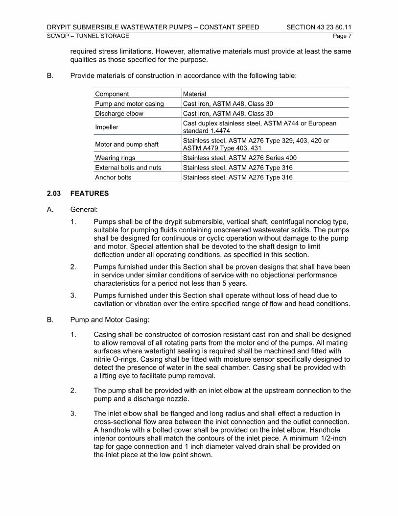
DRYPIT SUBMERSIBLE WASTEWATER PUMPS – CONSTANT SPEED SECTION 43 23 80.11SCWQP – TUNNEL STORAGE Page 7
required stress limitations. However, alternative materials must provide at least the same qualities as those specified for the purpose.
B. Provide materials of construction in accordance with the following table:
Component MaterialPump and motor casing Cast iron, ASTM A48, Class 30Discharge elbow Cast iron, ASTM A48, Class 30
Impeller Cast duplex stainless steel, ASTM A744 or European standard 1.4474
Motor and pump shaft Stainless steel, ASTM A276 Type 329, 403, 420 or ASTM A479 Type 403, 431
Wearing rings Stainless steel, ASTM A276 Series 400External bolts and nuts Stainless steel, ASTM A276 Type 316Anchor bolts Stainless steel, ASTM A276 Type 316
2.03 FEATURES
A. General:1. Pumps shall be of the drypit submersible, vertical shaft, centrifugal nonclog type,
suitable for pumping fluids containing unscreened wastewater solids. The pumps shall be designed for continuous or cyclic operation without damage to the pump and motor. Special attention shall be devoted to the shaft design to limit deflection under all operating conditions, as specified in this section.
2. Pumps furnished under this Section shall be proven designs that shall have been in service under similar conditions of service with no objectional performance characteristics for a period not less than 5 years.
3. Pumps furnished under this Section shall operate without loss of head due to cavitation or vibration over the entire specified range of flow and head conditions.
B. Pump and Motor Casing:
1. Casing shall be constructed of corrosion resistant cast iron and shall be designed to allow removal of all rotating parts from the motor end of the pumps. All mating surfaces where watertight sealing is required shall be machined and fitted with nitrile O-rings. Casing shall be fitted with moisture sensor specifically designed to detect the presence of water in the seal chamber. Casing shall be provided with a lifting eye to facilitate pump removal.
2. The pump shall be provided with an inlet elbow at the upstream connection to the pump and a discharge nozzle.
3. The inlet elbow shall be flanged and long radius and shall effect a reduction in cross-sectional flow area between the inlet connection and the outlet connection. A handhole with a bolted cover shall be provided on the inlet elbow. Handhole interior contours shall match the contours of the inlet piece. A minimum 1/2-inch tap for gage connection and 1 inch diameter valved drain shall be provided on the inlet piece at the low point shown.

DRYPIT SUBMERSIBLE WASTEWATER PUMPS – CONSTANT SPEED SECTION 43 23 80.11SCWQP – TUNNEL STORAGE Page 8
4. The discharge nozzle shall have a minimum 1/2-inch tap gage connection and a 1 inch diameter valved drain.
5. The casing shall be designed for support on individual concrete piers extending from the floor elevation indicated to the underside of the casing. The design of the support system shall provide convenient access to the inlet elbow gage taps, drain valve, and handhole cover.
C. Impellers:
1. The impeller shall be dynamically balanced, multi- vane, back-swept, non-clog design. The impeller vane leading edges shall be mechanically self-cleaned which shall keep them clear of debris, maintaining an unobstructed leading edge. The impeller(s) vanes shall have screw-shaped leading edges that are hardened to Rc 45 minimum and shall be capable of handling solids, rags, fibrous materials, heavy sludge and other matter found in waste water. Impellers shall be locked to the shaft and shall be coated with alkyd resin primer.
2. The impeller shall be trimmed to specifically meet the conditions of operation.
D. Bearings:
1. Bearings shall be heavy-duty permanently lubricated ball type. Bearings shall be designed for an L-10 life of 50,000 hours heavy-duty service without requiring additional lubrication.
2. All pump and motor bearings shall be fitted with bearing isolators specifically selected for the size and type of bearing. Bearing isolators shall be labyrinth, non-fretting type designed to expel contaminants by centrifugal force and prevent escape of lubricants. Bearing seals shall be Inpro/Seal or approved equal.
E. Pump Shaft:
1. The pump and motor shaft shall be the same unit, with the pump shaft being an extension of the motor shaft. Couplings shall not be acceptable.
2. The shaft shall be turned, ground and polished, of proportions suitable for use in the specified application. The shaft shall be of sufficient section to limit deflection at the shaft seal to not more than 4.0 mils when the pump is operating at any continuous-duty point defined by the envelope of conditions specified in this Section.
F. Mechanical Seals:
1. Tandem double mechanical seals running in an oil reservoir composed of two separate lapped face seals.
2. Lower seal:
a. Locate between pump and oil chamber.
b. One stationary rotating tungsten-carbide or silicon-carbide ring and one positively driven silicon-carbide or rotating carbon ring.

DRYPIT SUBMERSIBLE WASTEWATER PUMPS – CONSTANT SPEED SECTION 43 23 80.11SCWQP – TUNNEL STORAGE Page 9
3. Upper seal:
a. Locate between oil sump and motor housing.
b. One stationary tungsten-carbide or silicon-carbide ring and one positively driven silicon-carbide or rotating carbon ring.
4. Do not provide ceramic ring-type seals, conventional double mechanical seals with a single or double spring between rotating faces, or seals that require constant differential pressure to affect sealing and are subject to opening and penetration due to pumping forces.
5. Provide seals that do not require maintenance or adjustment and are easily replaceable.
6. Capable of submergence without loss of watertight integrity to a depth of 65 feet.
7. Seal lubricant chamber for the shaft sealing system:
a. Designed to ensure that an air pocket is provided in the seal lubricant chamber to absorb the expansion of the seal lubricant as the temperature varies.
b. Easily accessible drain and inspection plug with positive anti-leak seal.
G. Motor:
1. The pump motor shall be a squirrel-cage induction, shell type design, housed watertight chamber, NEMA B type with a service factor of 1.15 based on the nameplate rating. The motor shall be air cooled, be designed to be non-overloading over the entire pump curve, and confirm to applicable requirements specified in Section 43 05 21 – Common Motor Requirements for Equipment.
2. The motor shall be provided with motor winding thermostats, one in each winding, to protect the motor from overheating.
H. Cable:
1. Pump motor and detector cables shall be suitable for submersible pump applications. Pump motor and detector cables may be combined into one assembly or separate as standard for the pump manufacturer.
2. Each cable shall be a heavy-duty, flexible, water-resistant portable, UL listed cable, sealed at the motor bell and of sufficient length to connect to the associated junction box without any splices.
3. The cable entry into the motor shall be comprised of a single cylinder elastomer grommet or potted seal and shall prevent water from leaking into the motor due to capillary action even if cable is cut or damaged. Cables shall be water tight to a minimum depth of 65 feet.
I. Disconnecting Means:
1. Motors rated 480, 3-phase shall be provided with three phase receptacles and plugs as specified in Section 26 27 26 – Wiring Devices.

DRYPIT SUBMERSIBLE WASTEWATER PUMPS – CONSTANT SPEED SECTION 43 23 80.11SCWQP – TUNNEL STORAGE Page 10
2.04 EQUIPMENT AND SYSTEM CONTROLS
A. Pump motor starting equipment will be provided in the motor control center specified in Division 26.
B. Pump controls and automatic operation will be provided as part of the control system specified in Division 40.
2.05 SPARE PARTS
A. Procedures: Section 43 05 11 – General Requirements for Equipment
B. Provide the following spare parts:
1. One complete set of all gaskets and seals.
2. One complete set of all bearings.
3. One complete set of mechanical seals.
4. One complete set of discharge connection sealing devices.
PART 3 – EXECUTION
3.01 INSTALLATION
A. Equipment Mounting:
1. Procedures: Section 43 05 13 – Rigid Equipment Mounts
2. Install on a Group B Equipment Mounting System in accordance with the Equipment Mounting Schedule specified in Section 43 05 13 – Rigid Equipment Mounts.
3.02 COATINGS
A. Procedures: Section 09 90 00 – Coatings
B. Prime Coat: Shop applied, coating material per Section 09 90 00 – Coatings
C. Finish Coat: Field applied, coating material per Section 09 90 00 – Coatings
3.02 FIELD QUALITY CONTROL
A. Procedures: Section 01 75 00 – Commissioning
B. Performance Test:
1. Using clean water, measure pump flow and discharge pressure. Verify pump flow and discharge pressure is within the range of specified operating conditions.
2. Temporary flow meters and pressure gauges will be required.

DRYPIT SUBMERSIBLE WASTEWATER PUMPS – CONSTANT SPEED SECTION 43 23 80.11SCWQP – TUNNEL STORAGE Page 11
3. Throttle valve on pump discharge as necessary to achieve specified pump pressure within specified operating range.
4. Test level controls to verify pump control system operates as specified in this Section.
3.03 MANUFACTURER’S SERVICES
A. On-Site Inspections and Training: Provide a factory-trained manufacturer’s representative at the Site for the following activities. Specified durations do not include travel time to or from the site.
1. Installation Inspections: Assist, supervise, and inspect the Contractor’s activities during installation of submersible pumps. Provide 4 hours of installation inspection during installation of each pump.
2. Training Sessions: Procedures Section 01 79 00 – Demonstration and Training. Provide 2 hours of classroom training. Complete Form 43 05 11-B, Section 01 99 90 – Reference Forms.
END OF SECTION 43 23 80.11

FIBERGLASS REINFORCED PLASTIC TANKS FOR ACTIVATED CARBON SECTION 43 41 45.16SCWQP – TUNNEL STORAGE Page 1
PART 1 - GENERAL
1.01 SECTION INCLUDES
A. Scope:
1. This section specifies fiberglass reinforced plastic (FRP) tanks to serve as vapor phase activated carbon adsorbers.
2. Tanks provided under this section shall be horizontal, cylindrical, filament wound construction and supplied complete with all nozzles, level fittings, hatches, anchoring system, and other specified appurtenances.
3. The requirements of Section 06 70 13 – FRP Fabrications shall apply to all aspects of this specification section. For purposes of this section, references to design drawings, construction details, laminate sequences or laminate charts herein or contained in Section 06 70 13 – FRP Fabrications shall be construed as references to the Fabricator’s approved design submittal.
4. The tanks will contain activated carbon and will handle corrosive and potentially flammable wastewater gases.
5. Contractor shall install the activated carbon specified in Section 44 31 16 – Activated Carbon Absorption Odor Control Media.
B. Equipment List:
Item Equipment No.11th Avenue Carbon Odor Control Tank EBAL-200SCR5211th Avenue Carbon Odor Control Tank Differential Pressure Indicator 1 EBAL-200PDI52A
11th Avenue Carbon Odor Control Tank Differential Pressure Indicator 2 EBAL-200PDI52B
Fremont Shaft Carbon Odor Control Tank FRMT-200SCR52Fremont Shaft Carbon Odor Control Tank Differential Pressure Indicator 1 FRMT-200PDI52A
Fremont Shaft Carbon Odor Control Tank Differential Pressure Indicator 2 FRMT-200PDI52B
East Shaft Carbon Odor Control Tank WALL-200SCR52East Shaft Carbon Odor Control Tank Differential Pressure Indicator 1 WALL-200SCR52A
East Shaft Carbon Odor Control Tank Differential Pressure Indicator 2 WALL-200SCR52B
1.02 REFERENCE STANDARDS
A. REFERENCE STANDARDS: Section 06 70 13 – FRP Fabrications.

FIBERGLASS REINFORCED PLASTIC TANKS FOR ACTIVATED CARBON SECTION 43 41 45.16SCWQP – TUNNEL STORAGE Page 2
1.03 DEFINITIONS
(NOT USED)
1.04 SUBMITTALS
A. PROCEDURES: Section 01 33 10 – Submittals.
B. A copy of this specification section, with addendum updates included, and all referenced and applicable sections, with each paragraph check-marked to indicate compliance or marked to indicate requested deviations.
C. SUBMITTAL ITEMS:
1. A copy of this Section and Section 06 70 13 – FRP Fabrications, addendum updates included, with each paragraph check-marked to indicate compliance or marked to indicate requested deviations.
2. Complete design calculations certifying that the tanks have been designed to meet all specified design criteria. Calculations shall be signed and sealed by a professional engineer registered in the State of Washington. Calculations signed by a professional engineer registered in a state other than Washington will not be accepted.
3. Complete information developed by the Fabricator which describes specifically how the equipment is to be built. Information shall be provided in the form of shop drawings, standards, specifications, other shop instructions, or QC records. Information provided shall include, but not be limited to the following:a. Resin type.b. Type and amount of fillers.c. Nominal corrosion liner description.d. Reinforcement types for hand lay-up laminates.e. For filament wound laminates:
1) Helix angle.2) Glass content range.3) Strand yield.4) Strand per inch in the winding band.5) Ply thickness.6) Amount of chop or unidirectional roving interspersed with winding,
if any, and location within laminate.f. For all other components:
1) Construction type.2) Laminate thicknesses.3) Ply sequences.

FIBERGLASS REINFORCED PLASTIC TANKS FOR ACTIVATED CARBON SECTION 43 41 45.16SCWQP – TUNNEL STORAGE Page 3
4) Glass content range.g. For all secondary overlays (both interior and exterior):
1) Laminate thicknesses.2) Ply sequences and widths.
h. Construction details for all assembly and other special configurations, including:1) Bottom/top attachments with knuckle configuration and overlays
and thicknesses.2) Support and anchor lugs, including attachment details.3) Nozzles and installation, including cutout reinforcement,
gusseting, etc.4) Lateral or other support fabrication details, including ladder and
platform attachment clips and/or shoulders.5) Configuration and fabrication details of internals support system
and other specialty items.i. Assembly and erection plans as specified in Section 06 70 13- FRP
Fabrications.
4. Certification from the resin manufacturer that the selected resin and catalyst systems are appropriate for the service conditions, as specified in this Section and Section 01 11 80 – Environmental Conditions.
5. Inspector’s resume, a signed statement that the Inspector will have no other duties relating to the production of ductwork specified under this Section other than inspecting the ductwork, and a signed statement that the Inspector does not report to or is not supervised by any personnel involved in the production of the ductwork specified under this Section.
6. Signed affidavit by the tank Fabricator indicating that the tank was successfully factory tested.
7. Statement by the tank Fabricator certifying that the tank material meets the test properties specified.
8. Fabricator’s operating and maintenance information as specified in Section 01 78 23 – Operations and Maintenance Data.
9. Fabricator’s inspection reports as specified in Section 06 70 13 – FRP Fabrications.
10. Special Warranty as specified in Section 06 70 13 – FRP Fabrications.
11. Manufacturer’s Installation Certification Form, 43 05 11-A per Section 01 99 00 – Reference Forms, certifying that the equipment has been properly installed, aligned, and tested and meets all requirements for satisfactory performance under the conditions specified.

FIBERGLASS REINFORCED PLASTIC TANKS FOR ACTIVATED CARBON SECTION 43 41 45.16SCWQP – TUNNEL STORAGE Page 4
12. Manufacturer’s Instruction Certification Form, 43 05 11-B, per Section 01 99 00 – Reference Forms, certifying that instruction to operators has been completed.
1.05 QUALITY ASSURANCE
A. GENERAL: The requirements of Section 06 70 13 – FRP Fabrications shall apply to all aspects of this Section. In cases of conflict, the more stringent requirement shall apply.
B. SOURCE QUALITY CONTROL:
1. INDEPENDENT INSPECTION: The Fabricator shall provide an independent inspection as specified in Section 06 70 13 – FRP Fabrications.
2. ENGINEER’S INSPECTION: The Fabricator shall allow for two (2) factory inspections as specified in Section 06 70 13 – FRP Fabrications.
C. FACTORY TESTS:
1. GENERAL: Tanks shall be factory tested for compliance with the requirements specified herein and a certificate for the results of these tests shall be submitted to the Engineer upon delivery. In addition, the following specific tests specified below shall be conducted.
2. AIR INHIBITION TEST: Surfaces shall be tested for acetone sensitivity as an indication of air inhibition. Air-inhibited surfaces are not allowed.
3. BURN TEST: A minimum of two burn tests from nozzle cutouts shall be performed on each vessel to verify glass/resin ratio.
D. SHIPMENT AND STORAGE:
1. General requirements shall be as specified in Section 06 70 13 – FRP Fabrications.
2. All vessels that are shipped in a horizontal position shall be mounted on cradles contacting at least 120 degrees of the vessel circumference, be padded, and match the outside diameter within +1/8 inch, -0 inch. All end blocking to prevent shifting of Equipment must be padded.
3. In addition to the requirements specified in this Section, the Fabricator’s recommendations on shipping and handling and the shipping and handling procedures, as recommend by SPI “Recommended Practice for Shipping and Installation of Reinforced Plastic Tanks”, and as described in NBS PS15 and ASTM D4097 shall be adhered to.
E. SPARE PARTS
1. Provide the following spare parts:
a. Four (4) media life sampling probes per carbon vessel.
1.06 PERFORMANCE REQUIREMENTS
A. SERVICE CONDITIONS:

FIBERGLASS REINFORCED PLASTIC TANKS FOR ACTIVATED CARBON SECTION 43 41 45.16SCWQP – TUNNEL STORAGE Page 5
1. Equipment shall be suitable for installation and service under the environmental conditions specified in Section 01 11 80 – Environmental Conditions.
2. Equipment shall be designed for continuous outdoor operation and conveyance of foul air generated municipal wastewater processes treatment and conveyance processes. Foul air may contain methane, hydrogen sulfide, chlorine gas, sulfur dioxide, gasoline vapors, ammonia, grease, and water-saturated air. The air stream may contain droplets of dilute sulfuric acid.
B. OPERATING CONDITIONS
Equipment No. Air Flow, scfm Air Flow direction Max. Internal Vacuum, in w.c.
Max. Internal Pressure, in w.c.
EBAL-200SCR52 8,000 Horizontal -12 30FRMT-200SCR52 9,500 Horizontal -12 30WALL-200SCR52 8,000 Horizontal -12 30
C. DESIGN REQUIREMENTS:
Equipment No. Inside Diameter, feet
No. of Access Ports
No. of Carbon Beds
Carbon Bed Depth, feet
Mass of Wet Carbon Bed,
poundsEBAL-200SCR52 10 3 2 3 9,000FRMT-200SCR52 11 3 2 3 11,000WALL-200SCR52 10 3 2 3 9,000
1.07 SEISMIC ANCHORAGE AND STRUCTURAL DATA
A. Mechanical, instrumentation and control, electrical, nonstructural systems, components, and elements permanently attached to the structure shall be anchored and braced to resist seismic forces. The structural components, seismic attachments, braces, and anchors to the structure for all parts or elements of the mechanical and electrical systems shall be designed in accordance with Section 01 73 24 – Design Requirements for Non-Structural Components and Non-Building Structures.
PART 2 - PRODUCTS
2.01 CANDIDATE FABRICATORS/PRODUCTS
A. Candidate Fabricators are listed below. To conform with specified requirements, the Fabricator’s standard product may require modification.
1. ECS Environmental Solutions
2. Daniel Mechanical
3. Spunstrand
4. Approved substitute

FIBERGLASS REINFORCED PLASTIC TANKS FOR ACTIVATED CARBON SECTION 43 41 45.16SCWQP – TUNNEL STORAGE Page 6
2.02 MATERIALS
A. MATERIALS OF CONSTRUCTION:
Component MaterialVessel Fiberglass reinforced plastic (FRP)Gaskets NeopreneSample Ports (Port and Valve) CPVCMetal Appurtenances 316 Stainless Steel
2.03 FEATURES
A. GENERAL: The requirements of Section 06 70 13 – FRP Fabrications shall apply to all aspects of this Section. For purposes of this Section, references to Drawings, construction details, laminate sequences, or laminate charges herein or contained in Section 06 70 13 – FRP Fabrications shall be construed as references to the Fabricator’s approved design submittal.
B. FRP TANKS:
1. Tanks shall be fabricated and assembled as specified in the Contract Documents. Filament winding utilizing either a helical wind or a hoop wind in combination with weft unidirectional tape shall be the fabrication method. Filament winding angle shall be between 55 degrees and 65 degrees with a tolerance of ±2 degrees.
2. The Fabricator shall perform all calculations necessary to ensure long-term, low risk service of the FRP equipment with minimum reasonable maintenance requirements. The design shall ensure proper functioning of the equipment at the stated operating conditions. The design shall include as a minimum, engineering calculations, materials selection and documented physical and mechanical properties, and all detailed drawings required for fabrication and assembly of the equipment.
3. The design shall satisfy all applicable national, regional, and local design and building codes. Seismic forces shall be determined in accordance with the IBC for the tank fully loaded with carbon.
4. Detailed design of FRP tanks shall follow the procedures and methods, utilize the equations and formulas, and incorporate safety factors and allowable design stresses and strains set forth in ASME/ANSI RTP-1.
5. The design shall consider the interaction of the installed system including, but not limited to, thermal expansion of duct, tanks, and vessels and the effects of external loading from piping, fans, pumps, platforms, and other system components.
6. Tanks shall be shop assembled to assure proper fit. Subassemblies shall be numbered, and mating flanges or elements shall be match marked to assure correct alignment and field assembly.

FIBERGLASS REINFORCED PLASTIC TANKS FOR ACTIVATED CARBON SECTION 43 41 45.16SCWQP – TUNNEL STORAGE Page 7
7. The design shall allow for the most severe combination of conditions which may include any or all of the following:a. Internal or external pressure.b. Static head of contents (working and test conditions).c. Mass of structure and contents.d. Design temperature including upset conditions.e. Superimposed loads, such as seismic forces.f. Bending moments due to eccentric loads.g. Localized loads acting at supports, lugs, and other attachments.h. Shock loads.i. Loads due to heating or cooling and thermal gradients.j. Loads applied during transport or erection.k. Loads imposed by personnel during erection and operations.l. Fatigue.m. Specifically:
1) Shell overturning due to wind/seismic:a) Critical buckling.b) Design factor on tension side.
2) Anchoring, due to overturning or internal pressure:a) Lug design.b) Analysis of attachment to shell.c) Effect on shell knuckle.d) Maximum pullout forces and moments reported for the
foundation design.3) Appendage support:
a) Effect of point loads on shells.b) Interaction between towers under any load.c) Internal pressure or vacuum (with no water in the tank):d) Main shells, hoop and axial.e) Cutout reinforcements at nozzles.f) Effect on any discontinuities or special components, such
as internal cone.4) Thermal:
a) Differential expansion at temperature extremes.b) Thermal gradient through laminate.

FIBERGLASS REINFORCED PLASTIC TANKS FOR ACTIVATED CARBON SECTION 43 41 45.16SCWQP – TUNNEL STORAGE Page 8
5) Dead or live loads on domes.n. There will typically be other aspects which should be considered. It is the
responsibility of the Fabricator to identify and consider their effects and to provide this information to the Engineer for review.
8. The Fabricator shall provide documentation for all laminate properties used in the design. Laminates shall be similar in construction, layer sequence, resin type and cure to those used to determine tested properties. All properties shall be adjusted to reflect any reductions at operating temperatures.
9. Reinforcement surfacing veil shall be C-glass surfacing veil, as specified in Section 06 70 13 – FRP Fabrications.
10. Interior layers of glass mat shall consist of three layers of 1-1/2 ounce per square foot glass mat.
11. All exterior surfaces shall be resin rich and reinforced with one layer of C-glass surfacing veil.
12. Resin shall be premium grade vinyl ester resin, Vipel, Derakane, Dion, or approved substitute. Resin shall achieve ASTM Class I fire retardance without the use of antimony.
13. For all laminates, the corrosion resistant liner shall be followed by a filament wound structural laminate applied in accordance with Section 06 70 13 – FRP Fabrications.
14. The corrosion liner shall be a minimum of 100 mils in thickness and documentation shall be provided by the Fabricator verifying veil type, liner thickness, and resin cure. Excess liner thickness shall be added to the total wall thickness, but shall not conflict with tolerance requirements. Fifty mils of the corrosion liner shall be considered sacrificial and not included in determining structural wall thickness. Structural wall thickness shall be determined in accordance with ASME/ANSI RTP-1 and shall not be less than 0.375-inch for tanks and vessels. The requirements of ASME/ANSI RTP-1 shall govern the design.
15. Laminate types may include hand lay-up, helical winding, and hoop/chop construction methods. In laminates with helix angles greater than 75 degrees and in all hoop/chop laminates, approximately 10 percent of the structural wall thickness shall be oriented at 0 degrees (longitudinal direction). This reinforcement shall be applied in two layers of weft unidirectional fabric and equally spaced within the structural wall. Laminate defects and their allowable limits and tolerances shall be in accordance with Section 06 70 13 – FRP Fabrications. Laminates shall be designed for a minimum acceptable Barcol Hardness of 36.
16. Laminate sequences and thicknesses, as specified, shall be maintained.
17. Pigments shall not be used in the inner lamina. However, a pigmented surface coat shall be applied to the exterior surface of the tanks in accordance with

FIBERGLASS REINFORCED PLASTIC TANKS FOR ACTIVATED CARBON SECTION 43 41 45.16SCWQP – TUNNEL STORAGE Page 9
Section 06 70 13 – FRP Fabrications. The color shall be as directed in writing by SPU.
18. Nozzles, gussets, access ways and shell reinforcements shall be determined according to the applicable text, tables and formulas in ASME/ANSI RTP-1.
19. Anchoring for tanks shall be accomplished using lugs and a continuous filament wound band or an integral filament wound load ledge with external anchor clips.
20. Internal beams and support attachments shall be designed using a maximum of 25 psi shear stress for secondary bonds. This shall also apply to design of external lugs required for ladders, platforms, and other system components.
21. Tanks shall be designed to support the specified carbon bed depth. Carbon support system shall include a polypropylene carbon support membrane, as recommended by the carbon manufacturer, supported by fiberglass grating, supported by fiberglass beams. Carbon support system shall be designed to prevent carbon pellets from slipping through the grating. Carbon support system shall be coordinated with activated carbon supplier for pellet sizing. Carbon support system shall have a design safety factor of 300 percent.
C. ACCESS HATCHES:
1. Access hatches with clear acrylic covers shall be provided for each vessel. They shall be minimum 24-inch-diameter with flanged and bolted openings.
2. Each vessel shall have a minimum of one access hatch for each carbon bed.
D. FITTINGS: Drain flanges shall be ANSI 150#. Air inlet and outlet flanges shall be as specified in Section 23 31 16.16 – Fiberglass-Reinforced Plastic Ductwork.
E. METAL APPURTENANCES: Wires, anchor lugs, bolts, fasteners, and all other required metal appurtenances shall be provided as specified in this Section.
F. GASKETS: Gaskets shall be provided as specified in this Section.
G. AIR SAMPLE PORTS: Each tank shall have 1-1/2-inch-diameter air sample ports at the following locations at a minimum. Air sample ports shall be operator-accessible from ground-level.
1. One (1) port at the vessel intake plenum.
2. One (1) port located on the downstream side of each carbon bed.
H. GROUNDING: A bolted ground connection shall be provided on the exterior of the vessel for each carbon bed.
I. CARBON SAMPLE PORTS: Each carbon bed shall have three, 2-inch-diameter carbon sample ports extending 6 inches into carbon media. Ports shall be seated with a full port ball valve. Carbon sample ports shall be operator accessible from ground level.
J. CARBON BED MONITORING: A media life sampling probe to allow external viewing of the remaining carbon life shall be provided in each bed. Probe shall be sealed against

FIBERGLASS REINFORCED PLASTIC TANKS FOR ACTIVATED CARBON SECTION 43 41 45.16SCWQP – TUNNEL STORAGE Page 10
internal vessel air pressure. The media life sampling probe shall be operator accessible from ground level.
K. INSTRUMENTATION:
1. Pressure Differential Indicators
a. The equipment supplier shall provide a differential pressure indicator to measure pressure drop across each carbon bed. Pressure differential indicators shall conform to the requirements of Section 40 70 00 – Instrumentation for Process Systems.
b. The differential pressure indicator assembly shall be configured to prevent migration of water from the tubing into the gauge and be equipped with a valve/petcock to drain condensate from the tubing.
c. The differential pressure indicator shall be mounted to the unit and operator accessible from ground level.
PART 3 - EXECUTION
3.01 INSTALLATION
A. EQUIPMENT MOUNTING:
1. Install vessels on the cradle supports shown on the drawings. Cradle supports shall be coordinated with the specific vessel design to ensure a proper fit between the cradle and the vessel.
B. INSTALLATION OF CARBON:
1. The activated carbon specified in Section 44 31 16 – Activated Carbon Absorption Odor Control Media shall be installed.
2. The carbon shall be installed in strict accordance with manufacturer’s recommendations and the requirements of this Section. Carbon shall be evenly spread and compacted. Each bed shall be packed uniformly to the density specified in Section 44 31 16 – Activated Carbon Absorption Odor Control Media with the sample probes installed as specified.
3. The packed bed shall contain no void pockets, including bed areas around the sampling probes and near the vessel walls. Each bed shall have a smooth surface with uniform depth throughout and shall not be placed in lifts exceeding 1 foot in depth.
4. Contractor shall overfill the vessel to the top of the rectangular transition above each carbon bed to prevent short circuiting.
5. Notify the Engineer at least 10 working days prior to the scheduled date for carbon installation. Quantities of each type of carbon, a delivery date, and an installation time shall be provided. A representative of SPU shall be on site when the carbon is being installed. The representative shall be familiar with carbon vessel maintenance procedures and inspect each lift of carbon as it is installed.

FIBERGLASS REINFORCED PLASTIC TANKS FOR ACTIVATED CARBON SECTION 43 41 45.16SCWQP – TUNNEL STORAGE Page 11
3.02 COMPONENT TEST PHASE:
A. PROCEDURES: Section 01 75 00 - Commissioning.
B. TESTING: Prior to installation of carbon, perform the following tests:
1. AIR LEAK TEST:a. Connect tanks to ductwork system.b. Test tank and ductwork system under specified design conditions.c. Monitor tanks for air leaks and correct any leaks prior to acceptance.
END OF SECTION 43 41 45.16

GREASE FILTER / MIST ELIMINATOR SECTION 44 31 14SCWQP – TUNNEL STORAGE Page 1
PART 1 - GENERAL
1.01 SECTION INCLUDES
A. SCOPE:
1. This section specifies duct-mounted filters for removing grease and moisture from corrosive air streams
2. The installation of the grease filter/mist eliminator and filter must fit in the space available as shown.
B. EQUIPMENT LIST:
Item Equipment No.11th Avenue Mist/Grease Eliminator EBAL-200DF5111th Avenue Mist/Grease Eliminator Differential Pressure Indicator EBAL-200PDI51
Fremont Shaft Mist/Grease Eliminator FRMT-200DF51Fremont Shaft Mist/Grease Eliminator Differential Pressure Indicator FRMT-200PDI51
East Shaft Mist/Grease Eliminator WALL-200DF51East Shaft Mist/Grease Eliminator Differential Pressure Indicator WALL-200PDI51
1.02 REFERENCE STANDARDS
A. REFERENCE STANDARDS: This Section incorporates by reference the latest revisions of the following documents. They are part of this Section insofar as specified and modified herein. In the event of conflict between the requirements of this Section and those of the listed documents, the requirements of this Section shall prevail. Unless otherwise specified, references to documents shall mean the documents in effect on the effective date of Agreement. If referenced documents have been discontinued by the issuing organization, references to those documents shall mean the replaced documents issued or otherwise identified by that organization, or if there are no replacement documents, the last version of the document before it was discontinued.
Reference TitleSMACNA Thermoset FRP Duct Construction ManualNational Bureau of Standards Voluntary Product Standard PS 15-69
Custom Contact-Molded Reinforced-Polyester Chemical Resistant Process Equipment
B. ADDITIONAL REFERENCE STANDARDS: Section 06 70 13 – FRP Fabrications.
1.03 DEFINITIONS
(NOT USED)

GREASE FILTER / MIST ELIMINATOR SECTION 44 31 14SCWQP – TUNNEL STORAGE Page 2
1.04 SUBMITTALS
A. PROCEDURES: Section 01 33 10 – Submittals.
B. A copy of this Section and Section 06 70 13 – FRP Fabrications, addendum updates included, with each paragraph check-marked to indicate compliance or marked to indicate requested deviations.
C. SUBMITTAL ITEMS:
1. Detailed installation drawings showing equipment layout, size and location of all piping, and instrumentation and structural connections.
2. Certification from the resin manufacturer that the selected resin and catalyst systems are appropriate for service conditions, as specified in this Section and Section 01 11 80 – Environmental Conditions.
3. List of equipment components and materials.
4. Pressure drop data through filter pads.
5. Fabricator qualifications.
6. Special Warranty as specified in Section 06 70 13 – FRP Fabrications.
7. Applicable maintenance information as specified in Section 01 78 23 – Operations and Maintenance Data.
8. Instructions for installation of equipment. At a minimum, include the following information:a. Major parts list, including weights of component parts.b. Unpacking and unloading procedures, including directions indicating
proper methods for moving equipment.c. Instructions for field assembly of match-marked components, as they will
be shipped.d. Instructions for anchoring and securing equipment.e. Site storage and protection requirements for equipment prior to
installation.
1.05 QUALITY ASSURANCE
A. GENERAL: The requirements of Section 06 70 13 – FRP Fabrications shall apply to all aspects of this Section. In cases of conflict, the more stringent requirement shall apply.
B. SHIPMENT AND STORAGE: General requirements shall be as specified in Section 06 71 13 – FRP Fabrications.

GREASE FILTER / MIST ELIMINATOR SECTION 44 31 14SCWQP – TUNNEL STORAGE Page 3
1.06 PERFORMANCE REQUIREMENTS
A. SERVICE CONDITIONS:
1. Equipment shall be suitable for installation and service under the environmental conditions specified in Section 01 11 80 – Environmental Conditions.
2. Equipment shall be designed for continuous outdoor operation and conveyance of foul air generated municipal wastewater processes treatment and conveyance processes. Foul air may contain methane, hydrogen sulfide, chlorine gas, sulfur dioxide, gasoline vapors, ammonia, grease, and water-saturated air. The air stream may contain droplets of dilute sulfuric acid.
B. OPERATING CONDITIONS:
1. The grease filter/mist eliminator must remove 99.8 percent of all particles greater than 10 microns in diameter at 400 feet per minute face velocity. Face velocity through pads must not exceed 500 feet per minute to avoid carry-over.
2. Units must comply with the following:
Operating Condition ValueMax hydrogen sulfide concentration of air stream, ppm 100Max Internal Pressure, inches w.c. 30Max Internal Vacuum, inches w.c. -12
Equipment No. Capacity, scfm
Max. Pressure Drop at Ultimate Capacity with Filters Clean, in., W.C.
Connection Diameter,
inchesEBAL-200DF51 8,000 1.0 30FRMT-200DF51 9,500 1.0 30WALL-200DF51 8,000 1.0 30
1.07 SEISMIC ANCHORAGE AND STRUCTURAL DATA
A. Mechanical, instrumentation and control, electrical, nonstructural systems, components, and elements permanently attached to the structure shall be anchored and braced to resist seismic forces. The structural components, seismic attachments, braces, and anchors to the structure for all parts or elements of the mechanical and electrical systems shall be designed in accordance with Section 01 73 24 – Design Requirements for Non-Structural Components and Non-Building Structures.
PART 2 - PRODUCTS
2.01 CANDIDATE FABRICATORS/PRODUCTS
A. Candidate Fabricators are listed below. To conform with specified requirements, the Fabricator’s standard product may require modification.
1. AMACS

GREASE FILTER / MIST ELIMINATOR SECTION 44 31 14SCWQP – TUNNEL STORAGE Page 4
2. Daniel Mechanical
3. ECS
4. Approved substitute.
2.02 MATERIALS
A. MATERIALS OF CONSTRUCTION:
Component Material
Housing FRP as per Section 06 70 13 – FRP FabricationsFirst-stage pad Type 316 stainless steelSecond-stage pad Polypropylene or 316 stainless steelGaskets EPDMHardware Type 316 stainless steel Storage rack FRP as per Section 06 70 13 – FRP Fabrications
2.03 EQUIPMENT FEATURES
A. HOUSING:
1. The grease filter/mist eliminator filter shall consist of filter pads housed inside a fiberglass-reinforced plastic (FRP) enclosure suitable for outdoor installation.
2. Resin shall be premium grade corrosion-resistant vinyl ester resin manufactured by Vipel, Derakane, Dion, or approved substitute. Resin shall achieve ASTM Class I fire retardance without the use of additives such as nyacol or antimony. Finished laminate including liner and structure shall be translucent.
3. Provide housing with doors and chambers to access to filter pads from both sides of the filter housing.
4. The housing shall allow removal and replacement of filter pads through a hinged door fastened with stainless-steel, quick-release toggle clamps, and manual removal of the cartridges by one operator. The housing shall have a flanged inlet and outlet for installation in the air piping.
5. Provide access doors hinged with stainless-steel locking latches. The housing shall be able to withstand 30 inches of water column pressure and 12 inches of water column vacuum.
6. Housing shall be supplied with support legs and angle clips to attach the unit to an equipment pad. The support legs shall support the unit from below and result in a self-supported housing that does not rely on adjoining duct for support. Contractor shall determine leg length based on unit elevation. Supports and accessories shall be Type 316 stainless steel.
7. Housing shall be provided with a 2-inch-diameter, 2-inch-deep sump installed below the filter pads. The sump shall be equipped with a 2 inch FNPT drain coupling. The sump shall be designed to encourage moisture collection, prevent

GREASE FILTER / MIST ELIMINATOR SECTION 44 31 14SCWQP – TUNNEL STORAGE Page 5
plugging of the lower portion of the filter pads, and prevent moisture build-up in the unit.
8. Provide housing capable of achieving required pad face velocity for initial airflow by inserts or other means. Use removable inserts.
9. Provide an inlet transition with included angle of 60 degrees maximum, and an outlet transition with included angle of 90 degrees maximum. FRP construction housings must comply with the following:a. Use an opaque pigment coat for the exterior.b. Use a vinyl ester resin Nexus veil corrosion liner for the interior.c. Wall thickness must be no less than 3/8 inch.d. Use a polyvinyl chloride (PVC)-lined filter pad to protect the FRP
corrosion liner from scratching.
B. FILTER PADS:
1. The first pad is for grease removal and must be at minimum 2 inches thick. The second pad is for mist removal and must be at minimum 4 inches thick. Assemble the pads side-by-side to cover total filter face area. Use a water-washable pad.
2. Pads shall be assembled into a single cartridge, shall be removable by one operator for cleaning, and shall not exceed 40 pounds.
3. Candidate pad manufacturers include ACS, York, or approved substitute.
2.04 INSTRUMENTATION
A. Pressure Differential Indicators:
1. The equipment supplier shall provide a differential pressure indicator to measure pressure drop across the grease filter/mist eliminator filter pads. Pressure differential indicators shall conform to the requirements of Section 40 70 00 – Instrumentation for Process Systems.
2. The differential pressure indicator assembly shall be configured to prevent migration of water from the tubing into the gauge and be equipped with a valve/petcock to drain condensate from the tubing.
3. The differential pressure indicator shall be mounted to the unit and operator accessible from ground level.
2.05 STANDBY COMPONENTS
A. Provide one extra set of first- and second-stage filter pads per grease filter/mist eliminator.
B. The standby filter pads shall be installed in the filter pad storage rack specified in Paragraph 2.06.

GREASE FILTER / MIST ELIMINATOR SECTION 44 31 14SCWQP – TUNNEL STORAGE Page 6
2.06 FILTER PAD STORAGE RACK
A. The same vendor providing the grease filter/mist eliminator shall provide and install an FRP filter pad storage rack where indicated on the drawings. Installation shall be coordinated with other equipment to ensure adequate clearances for installation/removal of the filter pad from the storage rack.
B. The rack and anchorage shall be designed to support one complete filter pad.
C. Minimum FRP thickness and anchorage requirements shall be as indicated on the drawings.
PART 3 - EXECUTION
3.01 INSTALLATION
A. Equipment Mounting
1. Procedures: Section 43 05 13 – Rigid Equipment Mounts.
2. Install on a Group D Equipment Mounting System in accordance with the Equipment Mounting Schedule specified in Section 43 05 13 – Rigid Equipment Mounts.
B. Install each grease filter/mist eliminator as shown on the Drawings and recommended by the manufacturer. Support the unit so there is no strain on connected ducting. Install to ensure access for filter removal. Route drain pipe to the drainage system.
C. Permanently mark the two pressure gauges as recommended by the manufacturer for filter maintenance.
3.02 MEASUREMENT AND PAYMENT
A. Grease filter/mist eliminators shall not be paid for directly, but shall be considered incidental and included in the lump sum bid items in the Proposal Schedule.
END OF SECTION 44 31 14

ACTIVATED CARBON ADSORPTION ODOR CONTROL MEDIA SECTION 44 31 16SCWQP – TUNNEL STORAGE Page 1
PART 1 - GENERAL
1.01 SECTION INCLUDES
A. Scope:
1. This section specifies activated carbon for odor reduction.
B. Type:
1. Virgin activated carbon shall be non-impregnated, high surface area, tightly packed granular or pelletized type, specifically manufactured to absorb vapor phase organic and malodorous compounds of the type typically generated from municipal wastewater. Activated carbon shall be suitable for regeneration upon return to the supplier. Supplier of activated carbon shall be experienced in the supply and operation of activated carbon systems for vapor phase organic and hydrogen sulfide removal at wastewater treatment facilities.
1.02 REFERENCE STANDARDS
(NOT USED)
1.03 DEFINITIONS
(NOT USED)
1.04 SUBMITTALS
A. Procedures: Section 01 33 10 – Submittals.
B. A copy of this specification section, with addendum updates included, and all referenced and applicable sections, with each paragraph check-marked to indicate compliance or marked to indicate requested deviations.
C. The following submittals shall be provided:
1. Detailed product information for the activated carbon proposed for the job, including, but not limited to, verification of all properties specified in this Section, as well as total weight per carbon bed.
2. Certified weights of the water-saturated carbon beds.
3. Signed statement and reference list certifying that the manufacturer has at least five (5) years of experience in the supply of activated carbon systems for vapor phase hydrogen sulfide removal at wastewater facilities.
4. A detailed description of the procedure for installation and commissioning of the activated carbon.
1.05 QUALITY ASSURANCE
A. General:

ACTIVATED CARBON ADSORPTION ODOR CONTROL MEDIA SECTION 44 31 16SCWQP – TUNNEL STORAGE Page 2
1. Activated carbon shall be specifically manufactured for continuous exposure to moisture-laden foul air containing concentrations of hydrogen sulfide up to 10 parts per million, as well as other malodorous compounds of municipal sewage origin such as ammonia, organic sulfides, indols, skatols, aldehydes, and mercaptans. Activated carbon shall not contain clay or water-absorbing compounds. Foul air will have temperatures ranging from 30 to 95 degrees F and relative humidity up to 100 percent.
1.06 ENVIRONMENTAL CONDITIONS
A. Activated carbon shall be installed in the FRP tanks specified in Section 43 41 45.16 – Fiberglass Reinforced Plastic Tanks for Activated Carbon and shall be suitable for installation under the environmental conditions are specified in Section 01 11 80 – Environmental Conditions.
1.07 OPERATING CONDITIONS
A. Operating conditions shall be as summarized in the following table:
Operating Condition ValueMaximum temperature in vessel, degrees F 95Maximum face velocity in bed, fpm 50Bed thickness, ft 3.0Maximum H2S outlet at <1ppm inlet, ppm 0.05Maximum H2S outlet at 1-10 ppm inlet, ppm 0.1Minimum H2S removal at >10 ppm inlet, percent 99
PART 2 - PRODUCTS
2.01 CANDIDATE MANUFACTURERS/PRODUCTS
A. Candidate Manufacturers are listed below. To confirm with specified requirements, the Manufacturer’s standard product may require modification.
1. Evoqua Water Technologies
2. Haycarb
3. Jacobi
4. Approved substitute
2.02 MATERIALSVirgin Activated CarbonSubstrate Bituminous coal or coconut
shellParticle size (U.S. Sieve) 4 x 8Mean particle diameter, millimeters (per ASTM D2862) 3.4 - 3.8CCl4 number percent by weight minimum (per ASTM D3467) 60Hardness number minimum (per ASTM D3802) 95

ACTIVATED CARBON ADSORPTION ODOR CONTROL MEDIA SECTION 44 31 16SCWQP – TUNNEL STORAGE Page 3
Virgin Activated CarbonMaximum moisture content percent by weight (per ASTM D2867) 2Apparent density, minimum gms/cc (per ASTM D2854) 0.46 - 0.60Maximum head loss through bed at 50 fpm velocity inches w.c./ft bed depth1
0.8
H2S breakthrough capacity minimum, gms H2S removal/gm carbon2
0.04
Notes:1. Head loss shall be determined by passing dry air at 70 degrees F and 1 atm. pressure through
a 2-inch diameter by 12-inch deep bed of carbon placed in a dense packed arrangement per ASTM D2854.
2. The determination of H2S breakthrough capacity shall be made by passing a moist (70 percent RH) air stream containing 1 percent H2S at 1,450 cubic centimeters per minute flow through a test bed of uniformly packed activated carbon of the following dimensions: depth--9 inches, diameter--0.725 to 1.0 inch. The test shall be monitored to a 10 ppm breakthrough and the results expressed in gms H2S removal/gm carbon which is calculated from the carbon sample weight uncorrected for moisture.
PART 3 - EXECUTION
3.01 INSTALLATION
A. Carbon shall be installed in the vessels specified in Section 43 41 45.16 – FRP Tanks for Activated Carbon.
B. Installation procedures shall be as specified in Section 43 41 45.16 – FRP Tanks for Activated Carbon.
3.02 COMMISSIONING
A. The commissioning period shall be carried out under the supervision of the manufacturer's representative and shall be continuous for a minimum of 3 days.
3.03 TESTING
A. Prior to commissioning, a random sample of carbon selected by the Engineer shall be drawn from the delivered lot and sent to an independent certified laboratory for testing of the required H2S breakthrough capacity in grams of H2S per cubic centimeter of carbon, per ASTM D6646-03. Any media that does not meet the required H2S breakthrough capacity shall be removed at the Manufacturer’s expense from the site and replaced with media that meets the required specifications.
B. After completion of the commissioning period, each activated carbon bed shall be subjected to a performance test. The performance test shall extend for one year. During this year, the manufacturer shall supply a quarterly analysis of the activated carbon to be reported as hydrogen sulfide capacity. The manufacturer shall furnish the sufficient number of containers to accommodate the three sampling levels in each compartment of each activated carbon bed, as shown. The manufacturer shall also furnish instructions for sampling and disposition.

ACTIVATED CARBON ADSORPTION ODOR CONTROL MEDIA SECTION 44 31 16SCWQP – TUNNEL STORAGE Page 4
3.04 MEASUREMENT AND PAYMENT
A. Activated carbon adsorption odor control media shall not be paid for directly, but shall be considered incidental and included in the lump sum bids in the Proposal Schedule.
END OF SECTION 44 31 16