Improved productivity for complex machining
12
Sliding Headstock Type CNC Automatic Lathe Improved productivity for complex machining
Transcript of Improved productivity for complex machining

Sliding Headstock Type CNC Automatic Lathe
Improved productivity for complex machining

02 Cincom L2002 Cincom L20
CAV Bar Feeders
• Fully enclosed system
• Quick change separation system
• Space saving pusher design
• Automatic remnant retraction
• Integrated hydraulic tank, oil pump, oil-level indicator
• Shares same CNC controller and electrical system with Cincom machines
Cool Blaster High Pressure
Coolant System
• Up to 10 independent high pressure output lines
• Heat exchanger (standard on 10 line system)
• System control monitoring
• Clogged fi lter alarm with auto drain
• 5 micron fi lter system
• Space saving low profi le design
Cool Blaster Mist Control 850
• Triple Pass ESP Filtration Technology
• Variable Speed Controller
• Fused overload protection
• E stop interlock system
• Mounting hardware
SAVE TIME with the “CINCOM ADVAN-TAGE,” an exceptional opportunity for US manufacturers to obtain a turning center with all related accessories from one contact:
• High tech Citizen Swiss turning machines
• CAV Integrated Bar Feed Systems
• Cool Blaster Multi Port High Pressure Coolant Systems
• Cool Blaster Mist Control 850 mistand smoke control system
And there’s no need to let fi nancing hold you back—we also offer a leasing program that’s fast and easy.
Valuable production time can be wasted while you wait for fi nancing or while trying to coordinate support for your machine and all its accessories. With the Cincom Advantage you only need one contact for all your requirements—from purchasing to fi nancing to support!
Cincom Technology, Support and Financing.Marubeni Citizen-Cincom is your single source provider of Swiss type lathes and accessories.

Cincom L20 03
Now the Ultimate in Speed—the L20 Modular Series.
Streamline Control cuts non-cutting time to a minimum.
IMPROVE PRODUCTIVITY by reducing cycle time. The L20 accomplishes this by cutting idle time while maintaining existing high speeds and feeds with Citizen’s unique control method Streamline
Control. Idle time is reduced by:
• The tool holder’s overlap function that shortens the tool change time for gang tool holder and opposed tool holder
• The axis motion overlap function that is effective for thread cutting and other operations
• The direct spindle indexing function used for milling and drilling
However, the improvements are not restricted to the machine itself: the speed of operations has also been greatly improved. The time it takes to “start-up” when the power is turned on is one quarter of the time of existing machines. Power shut-off, which previously had to be delayed until the HDD (hard disk drive) stopped, can now be executed immediately, and the time to switch between screens at mode changes has been cut in half.
The new L20 series has a fl exible tooling line-up. Tools such as rotary tools that allow the simultaneous machining of front and back end faces, and tools whose mounting direction can be switched for the machining of an end face or cross machining, allows fl exibility when machining complex shapes. Attention has also been paid to the ease of maintenance. Reliability is improved through elimination of the HDD and by the sealed construction of the control unit.
Tool Overlap Function
For front machining, the L20 is equipped with an independently controlled gang tool holder and an opposed tool holder. Streamline Control positions the next tool holder while the previous tool holder retracts.
Direct Spindle Indexing
The Direct spindle indexing function signifi cantly reduces spindle indexing time. The spindle decelerates directly into the required index position, eliminating the time it takes to stop, reference and index.
The L20 is a machine that guarantees improved productivity.
The next tool advances while the previous tool retracts.

04 Cincom L20
User Friendly Operation
Swing-out Operation Panel
The operation panel with high visibility color screen pivots on two points, alllowing it to be conveniently positioned for tasks such as editing and tool setting.
PC Card Slot
NC programs can be input and output using the PC card slot on the front face of the operation panel. The slot cover can be closed while a PC card is inserted.
A design that puts the user fi rst by offering superb ease of operation

Cincom L20 05
Slide Cover with Wide Opening
To allow easy access to the cutting area, the slide cover has been given a wide opening which improves the accessibility of tool setting and machine maintenance.
In-machine Lighting
Fluorescent lighting is standard inside the cutting area for optimum visibility.
Part Chute
The product chute is positioned for fast part ejection after completion of back machining. As an option, the chute can be ‘cushion’ lined for delicate parts.
Part Receiver
The products collected by the chute are discharged to the part receiver box. Parts can also be discharged to an optional workpiece conveyor.
Coolant Tank
The large capacity (150 liters) coolant tank and 400W coolant pump help to maintain continuous production during unattended operation.
Centralized Lubrication System
Centralized lubrication to all ball screws eliminates manual greasing and reduces maintenance.

06 Cincom L20
The concept: “Strong, Fast, Flexible”
Developed to meet customer needs and demands
L20 Modular Design
The modular concept of the L20 (offered in 3 model types) can support a wide variety of machining processes depending on your current or future parts machining requirements. When only turning is required the L20 Type V offers 5 turning tools on the gang plate with no live tools. As future live tool needs are required, the Type V model can be upgraded by purchasing additional live tool holders that easily fi t into the existing gang tool plate. The L20 Type VII offers 5 turning and 5 live rotary tools (cross milling/drilling) on the gang plate. When cross machining is required three cross spindles—standard on the Type VIII model—can be mounted totaling eighteen tools: fi ve turning, seven rotary, and six drilling.
The type VIII uses a 3-tool cross/end-face drilling spindle [GSE1110] or a double-ended 6-tool cross/face drilling spindle [GSE1307]. Both units are normally indexable for either face or cross working, making the type VIII suitable for complex machining with multiple tools.
L20 Type VIII

Cincom L20 07
Tooling options for endless machining possibilities
GTF3712 (for type VIII) 1-tool holder
This is a tool holder for front turning that is mounted on the 5-rotary-tool vertical holder GSD103. The GTF3711 for back turning and grooving is also available.
L720-U121B (Front)L720-U151B (Back)Live tool units
Two live tool spindles and 1 fi xed sleeve. The front or back live tool unit replaces the existing stationary I.D. tool blocks and offers up to two live tools (GSE307) for end working. Also included are sleeves (SAU119) to ac-commodate stationary tools in live tool positions when necessary.
GDF506
End-drilling sleeve
holder
Mounted on a vertical holder, this holder is used for opera-tions including drilling on end faces. The sleeve mounting hole diameter is φ19.05 mm.
GDF1107
3-Sleeve Holder
For ¾" Shank Size Sleeve
LTR0183
Thread Whirling Unit
LTA0156
2” Saw Cutter Spindle
½ Spindle SpeedArbor size is 5/8"
GSE1110 (for type VIII) 3-tool cross machining/
end face drilling spindle
The mounting direction of this spindle can be switched for cross or end face machin-ing, and it can perform drill-ing on the outer diameter or drill on the end face. The maximum chuck diameter is φ10 mm and the chuck model is ER16.
GSC907 (for type VIII) Cross-drilling spindle
This spindle is for performing drilling on the outer diameter and milling on end faces. The maximum collet diameter is φ7 mm and the chuck model is ER11.
CSMCC0233
Adjustable Angle Holder
0 to 90 degrees2 spindles–ER16 collets
GSE607
End face drilling spindle
Used for operations includ-ing drilling on end faces. The angle can be adjusted within the range of 15º. The maximum collet diameter is φ7 mm and the chuck model is ER11.
GSE1307 (for type VIII)3-tool both-end face
drilling spindle
This spindle performs drilling on the front or back end face. It is capable of simultaneous machining on the front and back faces. The maximum collet diameter is φ7 mm and the chuck model is ER11.
GSC1010
Cross-drilling/milling
spindle
This spindle is for performing operations including drilling on the outer diameter and milling on end faces. The maximum collet diameter is φ10 mm and the chuck model is ER16.
GSE1407: BaseModular 6-position live
tool spindle
Front and back simultaneous forward rotation
GSE1507
Cross/Face drilling
spindle for GSE1407 (ER11 collet)
SAU621
Fixed sleeve adapter
for GSE1407
To be used in place of GSE1507 for installing fi xed ID tools
Modular tool range for turning, milling and drilling
08 Cincom L20
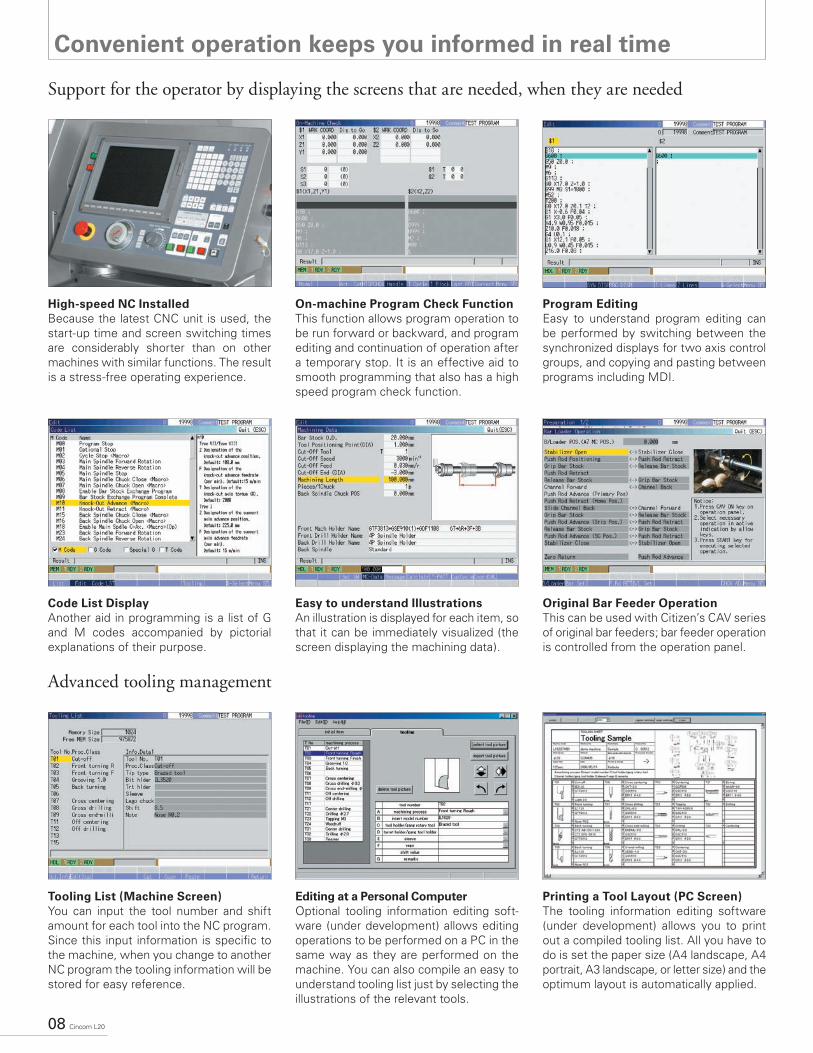
Convenient operation keeps you informed in real time
Support for the operator by displaying the screens that are needed, when they are needed
Advanced tooling management
High-speed NC Installed
Because the latest CNC unit is used, the start-up time and screen switching times are considerably shorter than on other machines with similar functions. The result is a stress-free operating experience.
Code List Display
Another aid in programming is a list of G and M codes accompanied by pictorial explanations of their purpose.
Tooling List (Machine Screen)
You can input the tool number and shift amount for each tool into the NC program. Since this input information is specifi c to the machine, when you change to another NC program the tooling information will be stored for easy reference.
On-machine Program Check Function
This function allows program operation to be run forward or backward, and program editing and continuation of operation after a temporary stop. It is an effective aid to smooth programming that also has a high speed program check function.
Easy to understand Illustrations
An illustration is displayed for each item, so that it can be immediately visualized (the screen displaying the machining data).
Editing at a Personal Computer
Optional tooling information editing soft-ware (under development) allows editing operations to be performed on a PC in the same way as they are performed on the machine. You can also compile an easy to understand tooling list just by selecting the illustrations of the relevant tools.
Program Editing
Easy to understand program editing can be performed by switching between the synchronized displays for two axis control groups, and copying and pasting between programs including MDI.
Original Bar Feeder Operation
This can be used with Citizen’s CAV series of original bar feeders; bar feeder operation is controlled from the operation panel.
Printing a Tool Layout (PC Screen)
The tooling information editing software (under development) allows you to print out a compiled tooling list. All you have to do is set the paper size (A4 landscape, A4 portrait, A3 landscape, or letter size) and the optimum layout is automatically applied.

Cincom L20 09
Easy machining of complex shapes
4 M3×0.5
φ14
φ1.520
3245
φ19
1 T08drill B1 T08
drill
B2 T32end mill
B3 T31boring
B4 T33center drill
6T03frontturning
12 T02grooving
13
T03frontturn-ing
15T05back turning
2 T09boring
7T06centerdrill 16 T01
cut-off
8 T07drill
10 T12drill
11 T13end mill
3 T21center drill
14 T04threadcutting
4 T22drill
5 T23gun drill
9 T11tap
Flexible multiple tooling combinations meet today’s sophisticated machining needs
Machine model:Material diameter:Material:Machining time:
L20-type VIIφ20.0Mild steel244 seconds
L20 Type VIII
Tooling sample
Cincom L20 09
10 Cincom L20
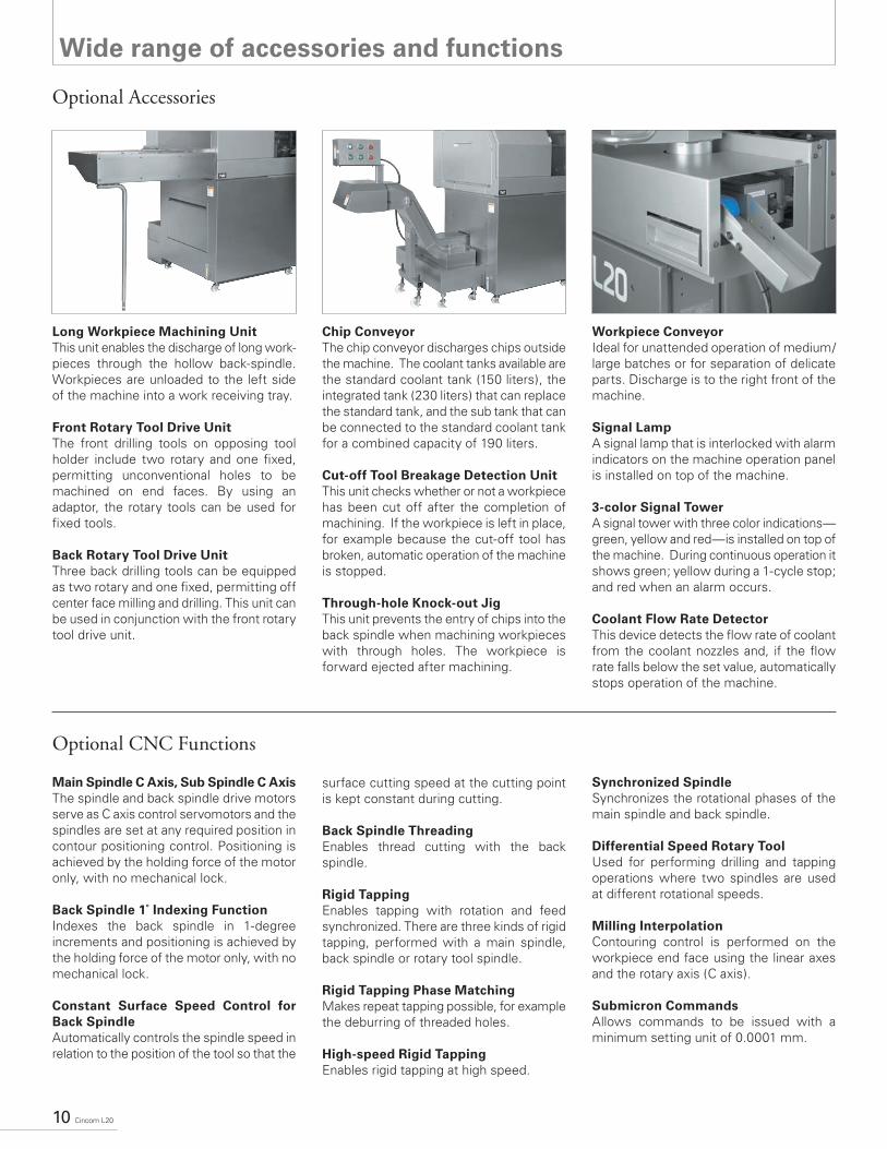
Wide range of accessories and functions
Long Workpiece Machining Unit
This unit enables the discharge of long work-pieces through the hollow back-spindle. Workpieces are unloaded to the left side of the machine into a work receiving tray.
Front Rotary Tool Drive Unit
The front drilling tools on opposing tool holder include two rotary and one fi xed, permitting unconventional holes to be machined on end faces. By using an adaptor, the rotary tools can be used for fi xed tools.
Back Rotary Tool Drive Unit
Three back drilling tools can be equipped as two rotary and one fi xed, permitting off center face milling and drilling. This unit can be used in conjunction with the front rotary tool drive unit.
Chip Conveyor
The chip conveyor discharges chips outside the machine. The coolant tanks available are the standard coolant tank (150 liters), the integrated tank (230 liters) that can replace the standard tank, and the sub tank that can be connected to the standard coolant tank for a combined capacity of 190 liters.
Cut-off Tool Breakage Detection Unit
This unit checks whether or not a workpiece has been cut off after the completion of machining. If the workpiece is left in place, for example because the cut-off tool has broken, automatic operation of the machine is stopped.
Through-hole Knock-out Jig
This unit prevents the entry of chips into the back spindle when machining workpieces with through holes. The workpiece is forward ejected after machining.
Workpiece Conveyor
Ideal for unattended operation of medium/large batches or for separation of delicate parts. Discharge is to the right front of the machine.
Signal Lamp
A signal lamp that is interlocked with alarm indicators on the machine operation panel is installed on top of the machine.
3-color Signal Tower
A signal tower with three color indications—green, yellow and red—is installed on top of the machine. During continuous operation it shows green; yellow during a 1-cycle stop; and red when an alarm occurs.
Coolant Flow Rate Detector
This device detects the fl ow rate of coolant from the coolant nozzles and, if the fl ow rate falls below the set value, automatically stops operation of the machine.
Main Spindle C Axis, Sub Spindle C Axis
The spindle and back spindle drive motors serve as C axis control servomotors and the spindles are set at any required position in contour positioning control. Positioning is achieved by the holding force of the motor only, with no mechanical lock.
Back Spindle 1˚ Indexing Function
Indexes the back spindle in 1-degree increments and positioning is achieved by the holding force of the motor only, with no mechanical lock.
Constant Surface Speed Control for
Back Spindle
Automatically controls the spindle speed in relation to the position of the tool so that the
surface cutting speed at the cutting point is kept constant during cutting.
Back Spindle Threading
Enables thread cutting with the back spindle.
Rigid Tapping
Enables tapping with rotation and feed synchronized. There are three kinds of rigid tapping, performed with a main spindle, back spindle or rotary tool spindle.
Rigid Tapping Phase Matching
Makes repeat tapping possible, for example the deburring of threaded holes.
High-speed Rigid Tapping
Enables rigid tapping at high speed.
Synchronized Spindle
Synchronizes the rotational phases of the main spindle and back spindle.
Differential Speed Rotary Tool
Used for performing drilling and tapping operations where two spindles are used at different rotational speeds.
Milling Interpolation
Contouring control is performed on the workpiece end face using the linear axes and the rotary axis (C axis).
Submicron Commands
Allows commands to be issued with a minimum setting unit of 0.0001 mm.
Optional Accessories
Optional CNC Functions

Cincom L20 11
Machine Layout
L20 Standard Machine
L20 Machine with Options
CAV20L-IS Bar Feeder (optional)
420
1094
539
3204
2110 127
785
958
Chip conveyorU90J
Long workpiece deviceU4120B
791
3-color signal towerU81Z
Workpiece conveyorU35J
Maintenance area
Machine body
218
0
1085
208
5
327
3050
06
6713
717
3
500
108
550
0
50021106003210
167 728
49357047
887 10
5017
70
490
148
89
1085
595
(U10R)
165 47722110 500 500 500
500
253
229
821 10
50 130
3
59726755003351010 3175 3501100
5034
8
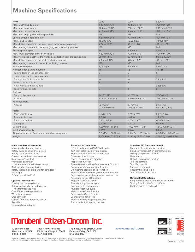
Item L20V L20VII L20VIIIMax. machining diameter φ20 mm (.79") φ20 mm (.79") φ20 mm (.79")Max. machining length 200 mm (7.87") 200 mm (7.87") 200 mm (7.87")Max. front drilling diameter φ10 mm (.39") φ10 mm (.39") φ10 mm (.39")Max. front tapping size (with tap and die) M8 M8 M8Spindle through-hole diameter φ24 mm (.94") φ24 mm (.94") φ24 mm (.94")Main spindle speed 10,000 rpm 10,000 rpm 10,000 rpmMax. drilling diameter in the rotary gang tool machining process φ7 mm (.28") φ7 mm (.28") φ8 mm (.32")Max. tapping diameter in the rotary gang tool machining process M6 M6 M6 Rotary spindle speed — 4,500 rpm 4,500 rpmMax. chuck diameter of the back spindle φ20 mm (.79") φ20 mm (.79") φ20 mm (.79")Max. workpiece length for the front side collection from the back spindle 80 mm (3.15") 80 mm (3.15") 80 mm (3.15")Max. drilling diameter in the back machining process φ8 mm (.32") φ8 mm (.32") φ8 mm (.32") Max. tapping diameter in the back machining process M6 M6 M6 Back spindle speed 8,000 rpm 8,000 rpm 8,000 rpmNumber of tools to be mounted 11 16 18~21 Turning tools on the gang tool post 5 5 5 Rotary tools on the gang tool post — 5 7 Rotary tools for front spindle — — 2 (option) Tools for front spindle 3 3 3 Rotary tools for back spindle — — 2 (option) Tools for back spindle 3 3 3Tool size Gang tool post (tool) ½" (T01 5⁄8" ) ½" (T01 5⁄8" ) ½" (T01 5⁄8" ) Sleeve φ19.05 mm (.75") φ19.05 mm (.75") φ19.05 mm (.75")Rapid feed rate All axes 32 m /min
(104.99 ft /min)32 m /min(104.99 ft /min)
32 m /min(104.99 ft /min)
Motor Main spindle drive 2.2 / 3.7 KW 2.2 / 3.7 KW 2.2 / 3.7 KW Tool spindle drive 1.0 KW 1.0 KW 1.0 KW Back spindle drive 0.75 /1.5 KW 0.75 /1.5 KW 0.75 /1.5 KW Cutting oil 0.4 KW 0.4 KW 0.4 KWCenter height 1,050 mm (41.34") 1,050 mm (41.34") 1,050 mm (41.34")Input power capacity 6 KVA 6 KVA 6 KVAAir pressure and air fl ow rate for air-driven equipment 0.5 MPa ・ 50 Nl /min 0.5 MPa ・ 50 Nl /min 0.5 MPa ・ 50 Nl /minWeight 2,100 Kg (4,629.7 lbs) 2,100 Kg (4,629.7 lbs) 2,100 Kg (4,629.7 lbs)
Machine Specifi cations
※ ※
Catalog No. L20 0507
Main standard accessories
Main spindle chucking device Rotary guide bushing drive device Rotary guide bushing device Coolant device (with level sensor) Door switch/Door lock Workpiece separator Lubrication device (with level sensor) Back spindle chucking deviceRotary tool spindle drive unit for gang tool *Work light * Only type VII and VIII
Optional accessories Fixed guide bushing device Rotary tool spindle drive device for
the front/back spindle Cut-off tool breakage detector Workpiece conveyor Chip conveyor Coolant fl ow-rate detecting device Signal lamp Long workpiece device
Standard NC functions
NC unit dedicated to CINCOM L series 10.4-inch color liquid crystal display Product counter display: Up to 8 digits Operation time display Nose R compensation function Preparation function Three-dimensional interference check function Corner chamfering rounding functionOn-machine program check functionMain spindle speed change detection functionBack spindle speed change detection functionAutomatic power-off functionProgram work area 160mThread cutting canned cycleContinuous threading cycleMultiple repetitive cycleMain spindle C axis functionBack spindle C axis functionCanned cycle for drillingMain spindle rigid tapping functionTool spindle rigid tapping function
Standard NC functions cont'd.
Back spindle rigid tapping functionSpindle synchronization control functionMilling interpolation functionUser macroHelical interpolation functionTool life control ITool life control IISub-inch commandCircular threading cycleTool offset pairs: 80 pairs
Optional NC functions
Program work area 320m, 600m or 1200mTooling function 1280m or 2560mCustom macro G code call