
Imports and Inventory Management System For Paramount ...
109
1 Imports and Inventory Management System For Paramount Impex (Pvt) Ltd M. Arqam Thahar BIT Registration No: R142134 BIT Index No: 1421344 Client: Mr.Saliheen Paramount Impex (Pvt) Ltd. Supervisor: M.P.D.S Pathirana Bachelor of Information Technology of the University of Colombo School of Computing
Transcript of Imports and Inventory Management System For Paramount ...

1
Imports and Inventory Management System
For
Paramount Impex (Pvt) Ltd
M. Arqam Thahar
BIT Registration No: R142134
BIT Index No: 1421344
Client: Mr.Saliheen
Paramount Impex (Pvt) Ltd.
Supervisor: M.P.D.S Pathirana
Bachelor of Information Technology of the
University of Colombo School of Computing

2
DECLERATION

3
ABSTRACT
Paramount Impex (Pvt) Ltd is a famous Hardware material importer in Colombo, Sri
Lanka. At present the Company supplies various types of hardware equipment
imported from various countries for both commercial and residential purposes. The
company has many shipments per month and they deliver their materials to the
customer in real time the shipment arrives to the shores.
Even though the Company is performing a numeric business critical tasks yet they use
to record activities and data manually, which gives an impact to the efficiently of the
productivity of Company. Also they have a risk such as losing data, tracking and
accuracy.
As a solution for this I have design a system as a solution. This system was developed
according to rapid application development and it also supports object oriented
concepts. This was implemented using Java programming language with MYSQL
server and Netbeans IDE. Unified Modeling Language was used for analysis and
designing phases.
The proposed system mainly handles Import orders, Customer, sales and stock
management. The system was developed to suit a standalone environment. Employee,
customer, agent and stock management are other areas which are managed by the
system. The system also manages report and chart generation. It supports managers to
achieve their business goals faster as they can make appropriate decisions more
efficiently.
As the system provides both functional and non-functional requirements which are
needed for the company, they can handle the system easily and efficiency while saving
time.

4
ACKOWLEDGEMENT
First and foremost I owe my deep gratitude to the University Of Colombo School Of
Computing for offering us this precious degree program and all its staff who guided
me from the beginning.
Also, I sincerely thank Mr. M.P.D.S. Pathirana for his guidance and encouragement in
carrying out this project work. I also wish to express my gratitude for Mr. Saliheen and
other staff members of Paramount Impex (PVT) Ltd, who rendered their help during
the period of my project work.
It is my duty to thank Mr. R.D.D.Suranga the Managing director¸ Mr. Susith anasuma,
Administrator, Lecture panel and all the staff at Earth University College, Colombo or
Giving me the academic knowledge for the BIT degree program and allowing me to
use the college library throughout the period. Also, I honestly thank all my friends of
Earth Institute and specially express my gratitude to my well educated lecturers who
helped me a lot in numerous ways and encouraged me to complete the project
successfully.
Finally I thank my family members for their unconditional love and support given in
every way possible throughout the process of this degree program of three years. Also
my special thanks to Danuka for supporting me in times of need.

5
TABLE OF CONTENTS
DECLERATION........................................................................................................................ 2
ABSTRACT ............................................................................................................................... 3
ACKOWLEDGEMENT ............................................................................................................ 4
TABLE OF CONTENTS ........................................................................................................... 5
LIST OF FIGURES ................................................................................................................... 8
LIST OF TABLES ................................................................................................................... 10
LIST OF ACRONYMS ........................................................................................................... 11
CHAPTER 1 : INTRODUCTION ........................................................................................... 12
Introduction .......................................................................................................................... 12
1.2 Motivation of the project ................................................................................................ 12
1.3 Objectives ....................................................................................................................... 13
1.4 Scope .............................................................................................................................. 13
CHAPTER 2 : ANALYSIS ..................................................................................................... 15
2.1 Current Manual System .................................................................................................. 15
2.1.1 Weakness of the current manual system. ................................................................. 15
2.2 Fact Gathering Techniques............................................................................................. 16
2.2.1 Reading existing company documents .................................................................... 16
2.2.2 Interviews and Discussion ....................................................................................... 16
2.2.3 Site visit ................................................................................................................... 17
2.3 Analyzing the current Manual System ........................................................................... 17
2.3.1 Outline of Existing Similar Solutions ...................................................................... 18
2.4. Identified Requirements for the Proposed System ........................................................ 19
2.4.1 Fictional requirements. ............................................................................................ 20
2.4.2 Non-Functional Requirements ................................................................................. 21
2.5 Selected Methodology of the System ............................................................................. 22
2.5.1 Waterfall model ....................................................................................................... 22
2.5.2 Incremental model ................................................................................................... 23
2.5.3 Agile model ............................................................................................................. 23
2.5.4 Rapid Application Model (RAD) ............................................................................ 23
CHAPTER 3 : DESIGN OF THE SOLUTION ....................................................................... 25
3.1 Introduction .................................................................................................................... 25
6
3.1 Feasibility Analysis ........................................................................................................ 25
3.1.1 Alternate Technical Solutions Evaluation ............................................................... 26
3.2 Selected Solution Description and Justification ............................................................. 26
3.3 Object oriented designing............................................................................................... 27
3.3.1 Use Case Diagram ................................................................................................... 27
3.3.2 Activity diagram ...................................................................................................... 29
3.3.3 Class diagram .......................................................................................................... 30
3.4 Database design .............................................................................................................. 30
3.4.1. Database normalization .......................................................................................... 31
3.5 User interface design ...................................................................................................... 32
CHAPTER 4 : IMPLEMENTATION ..................................................................................... 35
4.1 Implemented Environment ............................................................................................. 35
4.2 Development Tools ........................................................................................................ 35
4.2.1 Netbeans IDE 8.0.2 .................................................................................................. 36
4.2.2 Java Language ......................................................................................................... 36
4.2.3 MySQL .................................................................................................................... 37
4.2.4 JavaFX Scene Builder ............................................................................................. 38
4.2.5 Visual Paradigm ...................................................................................................... 38
4.2.6 Hibernate ................................................................................................................. 39
4.2.7 Jasper Report ........................................................................................................... 40
4.2.8 JPA - Java Persistence API ...................................................................................... 40
4.3 MVC Architecture .......................................................................................................... 42
4.4 Data Layer Implementation ............................................................................................ 43
4.4.1 Hibernate Configuration .......................................................................................... 43
4.4.2 Create Java Entities ................................................................................................. 45
4.5 Interface Layer Implementation ..................................................................................... 46
4.6 Control Layer Implementation ....................................................................................... 52
4.6.1 Hibernate Sessions ................................................................................................... 52
4.6.2 Data Access Objects (DAO) .................................................................................... 53
4.7 Reused Code Modules .................................................................................................... 54
CHAPTER 5 : EVALUATION ............................................................................................... 56
5.1. Test Strategies ............................................................................................................... 56
5.1.1. Unit Testing ............................................................................................................ 56
7
5.1.2. Integration Testing .................................................................................................. 56
5.1.3. System Testing ....................................................................................................... 57
5.2. Test Cases ...................................................................................................................... 57
5.3 Use Acceptance Testing ................................................................................................. 59
CONCLUSION ........................................................................................................................ 61
6.1 Introduction .................................................................................................................... 61
6.2 Lessons Learnt................................................................................................................ 61
6.3 Future Improvements ..................................................................................................... 62
REFERENCE ........................................................................................................................... 63
APPENDIX A: SYSTEM DOCUMENTATION .................................................................... 64
APPENDIX B: DESIGN DOCUMENTATION ..................................................................... 77
APPENDIX C: USER DOCUMENTATION .......................................................................... 91
APPENDIX D: MANAGEMENT REPORTS ........................................................................ 96
APPENDIX E: TEST RESULTS ............................................................................................ 98
APPENDIX F: CODE LISTING ........................................................................................... 101
APPENDIX G: CLIENT CERTIFICATE ............................................................................. 106
GLOSSARY .......................................................................................................................... 107
INDEX ................................................................................................................................... 108

8
LIST OF FIGURES
Figure 2. User Interface of the Crazy Vender online system 18
Figure 2. Screenshot of the Ship Station Online system 19
Figure 2. Work Flow of the Waterfall model 23
Figure 2. Rapid Application Development Model 24
Figure 3. Low Level Use Case Diagram of the system 27
Figure 3. Activity Diagram for the Customer Order 29
Figure 3. Class Diagram of the System 30
Figure 3. Overall ER Diagram of the system 31
Figure 3. User Login Interface 32
Figure 3. Interface Design for Employee Management 33
Figure 3. Interface Design for User Account reset 33
Figure 3. Error Prevention Notification 34
Figure 3. Notification on clearing a Form 34
Figure 4. Hibernate Framework 40
Figure 4. MVC Architecture 43
Figure User Satisfaction 60
Figure Installation progress of JVM (Step1) 62
Figure Installation progress of JVM (Step 2)-Select Optional features and click next65 62
Figure Installation progress of JVM (Step 3) 65
Figure Installation progress of JVM (Step 4)-Select destination folder to install 65
Figure Installation progress of JVM (Step 5) 66
Figure Installation progress of JVM (Step 6) "click Finish to complete the installation" 66
Figure Installation Progress MYSQL server (Step 1) 67
Figure Installation Progress MySQL server (Step 2)-Accept the License agreement 67
Figure Installation Progress MySQL server (Step 3) 68
Figure Installation Progress MySQL server (Step 4) 68
Figure Installation Progress MySQL server (Step 5) 69
Figure Installation Progress MySQL server (Step 6) 69
Figure Installation Progress MySQL Query Browser (Step 1) - "Click Next" 70
Figure Installation Progress MySQL Query Browser (Step 2)-Accept License Agreement 70
Figure Installation Progress MySQL Query Browser (Step 3)-Select destination 71
Figure Installation Progress MySQL Query Browser (Step 4)-Click "Finish" 71
9
Figure Open MySQL Administrator & Insert server host, port & the user name (Step5) 72
Figure Restore the database create a new database then select restore database (Step6) 74
Figure B. Activity Diagram for User Login. 77
Figure B. Activity diagram on User Account Creation. 78
Figure B. Activity diagram on making a Customer Order. 79
Figure B. Activity diagram on making an Import Order. 80
Figure B. Sequential Diagram Report Generation 81
Figure B. Add user account 82
Figure B. Add privileges to user accounts 82
Figure B. Creating a Customer Order 83
Figure B. Creating an Agent Import Order 83
Figure Structure of Item Table in database is given in Figure B.4.1 87
Figure Structure of Employee Table in database is given in Figure B.4.2 87
Figure Structure of Customer Table in database is given in Figure B.4.3 88
Figure Structure of Agent Table in database is given in Figure B.4.4 88
Figure Structure of Customer Order Table in database is given in Figure B.4.5 88
Figure Structure of Designation Table in database is given in Figure B.4.11 86
Figure Structure of Designation Table in database is given in Figure B.4.12 87
Figure C. Login Form and Main Window 91
Figure C Employee and User Management Forms 92
Figure C Privilege and Item Registry Management Forms 93
Figure C Customer and Agent Management Forms 94
Figure C Import Order and Customer Order Management From 95
Figure Details Reports 96
Figure User levels of the Company 100
Figure User Feedback Chart 100
Figure Structure of the Code 101
Figure loading a system Modules 102
Figure Code on Loading the Form 102
Figure Setting Style for the UI components 103
Figure Code for loading the Table 103
Figure Code on Add button 104
Figure Binding Method for Assigned date 105
Figure Binding Method for Designation 105
Figure Client Certificate 106

10
LIST OF TABLES
Table 3. Use case description for login 28
Table 3. Use case description for add customer details 28
Table 3. Use case description for add import order details 29
Table Test case for Customer Form 57
Table Test case for Employee Form 58
Table Test case for Agent Form 58
Table 1. Hardware Requirements for client application 64
Table 1. Software Requirements for client application 64
Table 3. Use case description for login 84
Table 3. Use case description for proving user privileges. 84
Table 3. Use case description for adding/updating an Item 84
Table 3. Use case description for add customer details 85
Table 3. Use case description for add importers details 85
Table 3. Use case description for add customer order details 86
Table 3. Use case description for add import order details 86
Table Test case for Customer Form 98
Table Test case for Employee Form 99
Table Test case for Agent Form 99

11
LIST OF ACRONYMS
BIT – Bachelor of Information Technology
CSS – Cascading Style Sheets
DAO – Data Access Objects
ERP – Enterprise Resource Planning
GUI – Graphical User Interface
HQL – Hibernate Query Language
IDE - Integrated Development Environment
JDBC – Java Database Connectivity
JRE – Java Runtime Environment
OMG – Object Managing Group
ORM – Object Relational Mapping
OS – Operating System
OOD - Object Oriented Design
OOP – Object Oriented Programming
OOAD – Object Oriented Analysis and Designing
POJO – Plain Old Java Objects
RAD – Rapid Application development
RDBMS – Relational Database Management System
RUP – Rational Unified Model
SDLC – Software Development Life Cycle
SQL - Structured Query Language
SQL – Structured Query Language
UML - Unified Modeling Language
UML – Unified Modeling Language
WWW – World Wide Web

12
CHAPTER 1 : INTRODUCTION
Introduction
Present days since the globalization many countries around the world are moving into
international trading. Countries with the natural resources produce more materials
with enormous production capacity and trade them with other countries with lesser
productions. Through evolvement of international trading people tend to innovate,
finding cost effective ways for production and finding new business opportunities
globally.
Paramount Impex is a company whom are mostly into international trading by
Importing Hardware materials from around the world and re-selling them
domestically. They import many kinds of hardware products as well as raw materials.
Paramount Impex are currently facing a lack of efficiency since they are working
with a manual system in maintaining and tracking their business activities. Therefore,
by developing Information system will help them increase the competency and
efficiency through reducing the heavy paper work and manage their day to day
activities effectively and efficiently.
1.2 Motivation of the project
At present Information Technology plays a vital role in companies in order to achieve
their business goals. Currently Paramount Impex uses a manual system for their
business activities. Therefore, they are undergoing difficulties such as loss of track on
sales, import, payment etc.
This manual system is very inefficient and has a hard time safeguarding the records.
So it is clear that having a computer based information system could give them a vast
advantage over manual system like speed, reliability, accuracy and confidentiality
which they require most for the success of the company.

13
The proposed system will help the company to reduce the issues which they are
currently facing as briefly mentioned earlier. Also by using Information Technology
Paramount Impex can generate reports systematically such as per no of imports made
under a particular agent, records of goods on store, summery of cash flows and few
other good related reports.
1.3 Objectives
The proposed system’s objective is to outline the solutions to enhance the efficiency
and the productivity of the company and also to minimize time consumption and
accuracy.
Improve the efficiency and the productivity of the company.
Increase and manage the profit and the losses.
Strengthen the good relationship with agents whom working with.
Improve the daily, monthly, annually statistical report generations on sales.
Enhance security and easy access to the system.
Maintain a track of all the business activities.
Help Employees to develop skills and to allow them to work enthusiastically.
1.4 Scope
When deciding to develop a system, the scope is a most important fact which we
need to consider about. The scope of this project will be as follows.
Developing an Inventory control system which has ability to:
Manage Customers, Agents details
Manage Imports and Invoice details on all business exchanges
Manage sales documents & payment details
Report generations to help make business decision based on the statistics

14
Critical functionalities:
Generating daily, weekly, annually transaction reports.
Manage Imports and Agents records.
Authentication and authorization control.
Notification management (such as payment dues)
Sales cancellations & Amendments.
Back up controlling for security.

15
CHAPTER 2 : ANALYSIS
The Merriam-Webster dictionary defines system analysis as "the process of studying
a procedure or business in order to identify its goals and purposes and
create systems and procedures that will achieve them in an efficient way". Another
view sees system analysis as the problem solving technique that breaks down a
system into its component pieces for the purpose of the studying how well those
component parts work and interact to accomplish their purpose
System analysis is one of the main phases in the software development life cycle.
System analysts will help to get an overall image of the system and will be able to
produce a high-level description of the system through this phase. Main objectives of
this phase are what services system should provide, required performance of the
system
2.1 Current Manual System
At the present all business functions of the company are done by manually. When a
Customer records are stored in paper documents. The import records and also the
stock updates are done the same manner as well. Employee registrations and their
valuable personal information are recorded in log books. It consumes a huge amount
of time to find required details about customers, employees, orders and importers
when the necessity occurs.
2.1.1 Weakness of the current manual system.
All documents are stored in hand written documents.
Safety and portability of the information in in risk
There are no data backup if the physical documents are destroyed.
Time consuming and it affects the efficiency of the company process.
Slow retrieval of data and High labor cost
Managers have a hard time on finding reports to make decisions.
Potential of making incorrect calculations and recording incorrect data.

16
2.2 Fact Gathering Techniques
Gathering client’s requirements by using the fact-finding techniques are the most
critical part in the analysis phase. When gathering the requirements, there should be a
proper way to handle these techniques. There are several fact-finding techniques
which can be used to collect the clear and accurate information. Below mentioned are
the fact-finding techniques I have used to gather requirements.
1. Reading Existing company documents
2. Interviews and Discussion
3. Site visit.
2.2.1 Reading existing company documents
One must have a clear understanding of business process to build up the system. This
is one of the best techniques to get a good and clear idea of hat the process is. Below
mention are some of the documents I referred.
Organizational charts
Company objectives & strategic Plan
Samples of Customer order and Import orders.
Payment bills
2.2.2 Interviews and Discussion
Ultimately, we have to offer the required system to its users. Therefore, it is very
important to know the requirements form its users. By interviewing employees of the
organization including the CEO, Managers, Store keepers share us their perspective
of things and suggest on how they can easy things much more with their vital
knowledge about the business.

17
2.2.3 Site visit
It is very important to get ideas about working station of Paramount Impex
environment and so a site visit is a must to do so before to start working on the
system. This completes our knowledge on how the process in carried out also in
which matter and the state of each business activity in actual timing.
2.3 Analyzing the current Manual System
Below figure shows the diagram of the entire existing system process in summery.
There are several users who are involved with system such as Manager of the
Company, Import agents, Customers and employees. The tasks which are allocated to
them are described in the diagram.
Figure 2.3. Manual System Process
1. Customer makes an order
2. Customer executive gives the invoice to finance manager to collect the payment
3. Store keeper check the Customer order
4. Customer makes the payments
5. Finance manager confirms the payment received and goods will be released
6. Notify the Import Executive running a low inventory
7. Makes an Import order
8. Receive the Import Order
9. Update the store
10. Make payments to agent
11. Manager makes the pricing
12. Admin adds new employees based on Managers confirmation.

18
2.3.1 Outline of Existing Similar Solutions
According to, there are several sales, purchase order and stock management systems
in the world. Some of them are freely available for online use for clients. Some of
them are listed below.
Crazy Vendor
Crazy Vendor is a flexible system that gathers all orders into one screen and
automates daily tasks, like label printing, tracking number submissions, drop
shipping, and stock control. Crazy Vendor also integrates 3rd party services such as
accounting, couriers, and ERP systems with providing a complete answer to every
business model. In this online system there are lots of features. Customer Database,
Customer Order Inquiry, inventory Management, Notifications, Real Time Order
Entry, Real Time Order Fulfillment are several features it has.
Below figure 2.3.1 shows some user interfaces of the Crazy Vender online system. It
shows the stock management form and the order management form.
Figure 2.3.1. User Interface of the Crazy Vender online system

19
Ship Station
This system is shipping and order management solution that integrates with most
Ecommerce sites and provides batch shipping and returns functionality. [1]
Customer database handling, order inquiry handling, real time order fulfillments,
return management and shipping management are some features which are included
in this online system.
Below figure 2.3.2 shows some screenshots of ship station online system. It shows
the order management form of the system.
Figure 2.3.2 Screenshot of the Ship Station Online system
2.4. Identified Requirements for the Proposed System
There are functional and non-functional requirements. Then we have to identify both
requirements.
Functional requirements
Non Functional requirements

20
2.4.1 Functional requirements.
This phrase describes on what functionalities the system has and does. This includes
functions by specific screens, outline of work flows performed by the system and
other business or company requirements the system must meet. Functional
requirements are classified as following.
Manage Employees user accounts.
The system keeps information of the employees of the company. Their personal
information and provides separate login to access the system to work on.
Import Agents Accounts
The system has a separate module on gathering and updating agent profiles and
their information. Also, this helps to review agents' details and generate profile
reports on each agent.
Customer Accounts
The system has a separate module on gathering and updating agent profiles and
their information. Also, this helps to review Customer details and generate profile
reports on each customer
Inventory Management
This records the stock been imported to the company and also been sold out to the
customers. It has track of Goods in the company store.
Privilege Management
Give separate access privilege to each user according to their role in the company
and designation.
Import Managements.

21
Tracking the imports orders that have made by the company and the status.
Customer Order Managements
Tracking the customers' orders that have made by them and the status.
Report generation
Generate reports according to the Agent, Stock, and Customers activities.
2.4.2 Non-Functional Requirements
Reliability
System provides accurate information about sales, stocks, and import order, Agents
and customers details. Top management can rely on the information generated
through the system
User Friendliness
Has a basic user interface which is very much friendly for the user to work on? Any
new user can easily learn and adapt to the system without and hassle.
Accessibility
User can access to the system fast because it is a standalone system.
Security
By providing access privileges to different users accordingly help to keep the security
level high.
Maintainability

22
Maintaining the system is easy because the company doesn’t want to spend extra cost
for like web based system.
Availability
System can use any time to get information. Internet connection problems are not an
effect to the system unlike web base systems.
Efficiency and consistency
System can handle day to day business transactions efficiently without delay.
2.5 Selected Methodology of the System
The development models are the various processes or methods that are selected for
the development of the project based on the project’s aims and goals. There are many
development life cycle models that have been developed to achieve different
important objectives. The models stipulate the various stages of the process and the
order in which they are carried out. There are various Software development models
or methodologies. They are as follows:
2.5.1 Waterfall model
The Waterfall Model was the first Process Model to be introduced. It is also referred
to as a linear-sequential life cycle model. It is very simple to understand and use. In a
waterfall development modal requirements analysis, design, implementation, testing,
integration and maintenance, must be completed before the next phase can begin and
there is no overlapping in the phases. [2]

23
Figure 2.5.1 Work Flow of the Waterfall model
2.5.2 Incremental model
In incremental model the whole requirement is divided into various parts. Multiple
development cycles take place here. These cycles are divided up into smaller,
modules which are easier to handle. Each module passes through the requirements,
design, implementation and testing phases. A working version of software is
produced during the first module, so you have working software early on during the
software life cycle.
2.5.3 Agile model
Agile development model is also a type of Incremental model. Software is developed
in incremental, rapid cycles. Each release of module go on to improve the previous
functionality. Each release is thoroughly tested to ensure software quality is
maintained. It is used for time critical applications
2.5.4 Rapid Application Model (RAD)
When compared to traditional life cycles, Rapid Application Development (RAD)
development cycle gives much faster development and higher-quality results. The
most important aspect for this model to be successful is to make sure that the

24
prototypes developed are reusable. RAD model distributes the analysis, design, build,
and test phases into a series of short, iterative development cycles Therefore Rapid
Application Development is used as the process model of Tile Management System
for Paramount Impex PVT LTD. [3]
Figure 2.5.4 Rapid Application Development Model

25
CHAPTER 3 : DESIGN OF THE
SOLUTION
3.1 Introduction
According to the IEEE definition, design is both “the process of defining the
architecture, components, interfaces, and other characteristics of a system or
component” and “the result of [that] process”. In the Design Phase, the system is
designed to fulfill the requirements recognized in the previous phases. The
requirements identified in the Requirements Analysis Phase are converted into a
System Design Document that accurately defines the design of the system and that
can be used as an input to system development in the next stage.
3.1 Feasibility Analysis
Feasibility analysis helps to explore alternative solutions of system design according
to the way of development, the hardware environment and the choice of system
software. When developing software there is a range of options which can be
evaluated by an analyst such as;
Do nothing
Re engineer business process
Enhanced existing computer process
Purchased packaged software
Stand-alone system or
Web based system
In Paramount Impex PVT LTD there is only paper and file based manual system and
it needs to build a new automated system to enhance its operations. It can be a
Standalone system or a web base system. But in order to decide to choose on which
to build we should do a proper analysis.

26
3.1.1 Alternate Technical Solutions Evaluation
There are two different alternate solutions identified for developing imports and
inventory, sales and order system. They are,
Web based system Web-Based systems refers to those applications or services that
are resident on a server that is accessible using a Web browser and is therefore
accessible from anywhere in the world via the Web.
Standalone system the standalone system refers to a software program work offline.
In standalone application database and all the information is stored on the local
computer and no server is needed. Usually standalone systems are faster than web
based systems.
In choosing a system for Paramount Impex they have a lot of paper documents needs
to be recorded and safe guarded on their business transactions. To do so the most
suitable solution is a standalone system.
3.2 Selected Solution Description and Justification
When developing the system we must prioritize the clients’ interests and their
requirements in the first place. During the data gathering stage it was revealed that
the client particularly needs a standalone system. Therefore the Imports and
Inventory Management system was designed to build as a standalone system. Also
when comparing a stand-alone system and a web based system can perform much
faster than web based system or software collection. Also as there is only one branch
and few employees in this company so there is no need of an intranet or networking.
According to the feasibility analysis matrix also it was proved with highest score that
it is worth to develop a standalone system than a web based system. If we considered
a web based system it refers to a program that runs with the help of the internet. To
implement a web based system additional resources such as a server, hardware
(router, bridge and network cables) are essentially needed. The deployment,
updating, maintenance processes are time consuming. In the case of a network failure
the system is unavailable. Web based system most suitable for large scale business

27
and if there are several branches. Therefore the choice for the Imports and Inventory
Management system development was a stand-alone system.
3.3 Object oriented designing
Object-oriented analysis and design (OOAD) is a popular technical approach to
Analyzing, designing an application, system, or business by applying the object-
oriented Paradigm and visual modeling throughout the development life cycles to
Foster better stakeholder communication and product quality. [4]
3.3.1 Use Case Diagram
There are several users in the system who logs in to do day to day operations of the
company. There are Mangers, Administrators, Agents and Customer Executives and
Storekeepers. Below figure shows the high level interactions and activities of the
main parties who assist the system.
Figure 3.3.1. Low Level Use Case Diagram of the system

28
Use case descriptions
Below table 3.3.1 use case descriptions for login to the system. It describes the
actors, Pre-conditions, post conditions and flow of the event of the login use case.
Use case Login
Actors All Users (Managers, Executives, Store keepers)
Description Registered users can log into the system
Pre- Condition Users must be registered with the system and must have a
valid user name and password
Flow of events Enter a valid user name and password.
Post conditions Show an error massage, Reject login to the system
Table 3.3.1: Use case description for login
Below table 3.3.2 shows the use case description for adding customer details to the
system. It describes the actors, pre-conditions, post conditions and flow of the event
of the adding customer details use case.
Use case Add customer details
Actors Customer Executive
Description Adding details about new customers
Pre- Condition Uses must login to the system
Flow of events Enter new customers and save
Post conditions New records available in the company database
Table 3.3.2: Use case description for add customer details
Below table 3.3.3 shows the use case description for adding an import order to the
system. It describes the actors, pre-conditions, post conditions and flow of the event
of the adding purchase details use case. Import Executive is the actor of the use case.

29
Use case Add import order details
Actors Imports Executive
Description Adding details about an order from supplier (Import
agent)
Pre- Condition Agent should supply their relevant order
Flow of events User fills the forms generated by the system.
Post conditions Create the order sheet
Table 3.3.3: Use case description for add import order details
3.3.2 Activity diagram
Activity diagrams represent the dynamic behavior of a system. They may also be
created to graphically show the workflow for an operation. Activity diagrams are
similar to flow charts. Below shows the Activity diagram of a Customer order.
Figure 3.3.2 Activity Diagram for the Customer Order

30
3.3.3 Class diagram
Class diagram is the backbone of nearly all Object Oriented methods. It describes the
structure of a system by showing the system’s classes and relationships among the
classes. These classes can be people, things or data.
The following class diagram in Figure 3.5 depicts the overall class diagram of the
system.
Figure 3.3.3 Class Diagram of the System
3.4 Database design
Database design is the process of producing a detailed data model of a database. This
is a technique used for defining business requirements for a database. Data
redundancy means some data fields appear more than once in the database and it is
inefficient. The process of Normalization is used to reduce the data redundancy.

31
3.4.1. Database normalization
1st Normal Form Sets the very basic rules for an organized database Eliminate
duplicative columns from the same table. Create separate tables for each group of
related data and identify each row with a unique column or set of columns (the
primary key).
2nd Normal Form Second normal form (2NF) further addresses the concept of
removing duplicative data o Meet all the requirements of the first normal form. o
Remove subsets of data that apply to multiple rows of a table and place them in
separate tables. Create relationships between these new tables and their predecessors
through the use of foreign keys
3rd Normal Form Third normal form (3NF) goes one large step further o Meet all the
requirements of the second normal form. Remove columns that are not dependent
upon the primary key.
Figure 3.4.1. Overall ER Diagram of the system

32
The 10 most general principles for interaction design. They are called 'heuristics’.
Visibility of system status
Match between system and the real world
User control and freedom
Consistency and standards
Error prevention
Recognition rather than recall
Flexibility and efficiency of use
Aesthetic and minimalist design
Help users recognize, diagnose, and recover from errors
Help and documentation
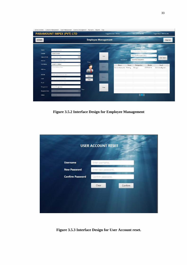
3.5 User interface design
When creating the proposed system above principles were achieved as much as
possible. Some of the user interfaces are shown Figure 3.5.1, Figure 3.5.2 and Figure
3.5.3.
Figure 3.5.1. User Login Interface
33
Figure 3.5.2 Interface Design for Employee Management
Figure 3.5.3 Interface Design for User Account reset.

34
Figure 3.5.4 Error Prevention Notification
Figure 3.5.5 Notification on clearing a Form
35
CHAPTER 4 : IMPLEMENTATION
4.1 Implemented Environment
When selecting set of software tools & other resources to implement the system,
several aspects were considered such as hardware & software requirements of the
business organization, the environment of the proposed system, maintainability,
technical feasibility, high performance & the user friendliness.
Hardware Requirements:
Basic hardware performance which needs to run the system
Computer with processing power similar or higher than 3.06 GHz
RAM with 2 GB or above.
Hard Disk with 160 GB or above.
Software Requirements:
Software which were used to create the system
MySQL Server 5.5.
MySQL Query Browser.
MySQL Workbench.
NetBeans IDE.
JavaFX Scene Builder.
Windows 10.
Visual Paradigm
4.2 Development Tools
When building a production software one will have to make use of the right
developing tools to achieve the maximum success and capacity of the system. Below
mention are the soft wares which used to build the Imports and Inventory
Management system.

36
4.2.1 Netbeans IDE 8.0.2
Netbeans 8.0.2 version was used as the IDE for the development of the system.
NetBeans IDE 8.0.2 provides out-of-the-box code analyzers and editors for working
with the latest Java 8 technologies such as Java SE 8, Java SE Embedded 8, and Java
ME Embedded 8.
The NetBeans IDE is written in Java and can run on Windows, OS X, Linux, Solaris
and other platforms supporting a compatible JVM. Netbeans IDE provides all the
tools necessary to develop desktop, enterprise, web and mobile applications. The IDE
also has a range of new enhancements that further improve its support for Maven and
Java with Prime Faces, new tools for HTML5, in particular for AngularJS and
improvements to PHP and C/C++ support.
The NetBeans IDE is a Framework for simplifying the development of Java Swing
desktop applications. It has bundled for Java SE contains what is needed to start
developing NetBeans plugins and NetBeans Platform based applications, no
additional SDK is required. Profiler is a module that helps to track the speed and
memory usage of an application to help identify bottlenecks and memory leaks.
Working together on open source projects is provided by the Developer
Collaboration. And the Netbeans Platform is intended to be used for APIs, are
provided to help make desktop applications easier by handling some of the more
common tasks (e.g., menus, window management, file access). It facilitates bundle
for Java SE contains what is needed to start developing NetBeans plugins and
NetBeans Platform based applications; providing user interface management,
windows management & many more. Netbeans contains highlighted features as,
Swing GUI Builder which provides drag and drop Swing components to build an
application's GUI [5]
4.2.2 Java Language
Java is a general-purpose computer programming language that is concurrent, class-
based, object-oriented, and specifically designed to have as few implementation
dependencies as possible. It is intended to let application developers "write once, run

37
anywhere" (WORA), meaning that compiled Java code can run on all platforms that
support Java without the need for recompilation.
With a reported 9 million developers, Java is one of the most popular programming
languages in use as of 2015, particularly for client-server web applications. Java was
originally developed by James Gosling at Sun Microsystems (which has since been
acquired by Oracle Corporation) and released in 1995 as a core component of Sun
Microsystems' Java platform. The language is mostly derived from C and C++, but it
has fewer low-level facilities than either of them.
The original and reference implementation Java compilers, virtual machines, and
class libraries were developed by Sun from 1995. As of May 2007, in compliance
with the specifications of the Java Community Process, Sun relicensed most of its
Java technologies under the GNU General Public License. Others have also
developed alternative implementations of these Sun technologies, such as the GNU
Compiler for Java and GNU Class path.
Java uses an automatic garbage collector to manage memory in the object lifecycle.
The programmer determines when objects are created, and the Java runtime is
responsible for recovering the memory once objects are no longer in use. Once no
references to an object remain, the unreachable memory becomes eligible to be freed
automatically by the garbage collector [6]
4.2.3 MySQL
MySQL is a Relational Database Management System (RDBMS). In July 2013 it was
the world's second most widely used RDBMS, and the most widely used open-source
RDBMS. It is named after co-founder Michael Widenius's daughter, my. The SQL
acronym stands for Structured Query Language. The MySQL development project
has made its source code available under the terms of the GNU General Public
License, as well as under a variety of proprietary agreements. MySQL was owned
and sponsored by a single for-profit firm, the Swedish company MySQL AB, now

38
owned by Oracle Corporation. For proprietary use, several paid editions are
available, and offer additional functionality.
The MySQL Query Browser is a graphical tool for creating, executing, and
optimizing queries in a graphical environment. The MySQL Query Browser is
designed to help query and analyze data stored within MySQL database.
The official MySQL Workbench is a free integrated environment developed by
MySQL AB, which enables users to graphically administer MySQL databases and
visually design database structures. MySQL Workbench replaces the previous
package of software, MySQL GUI Tools [7]
4.2.4 JavaFX Scene Builder
JavaFX Scene Builder is a visual layout tool that lets users quickly design JavaFX
application user interfaces, without coding. Users can drag and drop UI components
to a work area, modify their properties, apply style sheets, and the FXML code for
the layout that they are creating is automatically generated in the background. The
result is an FXML file that can then be combined with a Java project by binding the
UI to the application’s logic.
JavaFX Scene Builder is a visual layout tool that lets users quickly design JavaFX
application user interfaces, without coding. Users can drag and drop UI components
to a work area, modify their properties, apply style sheets, and the FXML code for
the layout that they are creating is automatically generated in the background. The
result is an FXML file that can then be combined with a Java project by binding the
UI to the application’s logic. It Helps designers and developers to build JavaFX-
based UIs &Scene Builder are fully written with JavaFX 2.0 APIs to explore and
learn about JavaFX objects [8]
4.2.5 Visual Paradigm
Visual Paradigm for UML (VP-UML) is a UML CASE Tool supporting UML 2,
SysML and Business Process Modeling Notation (BPMN) from the Object
39
Management Group (OMG). In addition to modeling support, it provides report
generation and code engineering capabilities including code generation. It can reverse
engineer diagrams from code, and provide round-trip engineering for various
programming languages. The tool has a good working environment, which facilitates
viewing and manipulation of the modeling project. It is a business tool and also
supports specific changes to source code of some programming languages such as
C++ and Java [9]
4.2.6 Hibernate
Hibernate ORM (Hibernate in short) is an object-relational mapping framework for
the Java language, providing a framework for mapping an object-oriented domain
model to a traditional relational database. Hibernate solves object-relational
impedance mismatch problems by replacing direct persistence-related database
accesses with high-level object handling functions. Hibernate is free software that is
distributed under the GNU Lesser General Public License. Hibernates primary
feature is mapping from Java classes to database tables (and from Java data types to
SQL data types). Hibernate also provides data query and retrieval facilities. It
generates SQL calls and relieves the developer from manual result set handling and
object conversion. Applications using Hibernate are portable to supported SQL
databases with little performance overhead. HQL is abbreviation of Hibernate Query
Language. HQL is SQL inspired language provided by hibernate. Developer can
write SQL like queries to work with data objects [10]
Below figure 4.1 shows the architecture of Hibernate. The top layer is the application
layer that contains application program, which has transient object called Plain Old
Java Object (POJO)

40
Figure 4.2.6 Hibernate Framework
4.2.7 Jasper Report
Jasper Reports is an open source Java reporting tool that can write to a variety of
targets, such as: screen, a printer, into PDF, HTML, Microsoft Excel, RTF, ODT,
Comma-separated values or XML files. It can be used in Java-enabled applications,
including Java EE or web applications, to generate dynamic content. It reads its
instructions from an XML or jasper file.
Jasper Reports provides necessary features to generate dynamic reports, including
data retrieval using JDBC (Java Database Connectivity), as well as support for
parameters, expressions, variables, and groups. Jasper Reports also includes
advanced features, such as custom data sources, script lets, and sub reports.
4.2.8 JPA - Java Persistence API
The Java Persistence API (JPA) is a Java specification for accessing, persisting, and
managing data between Java objects / classes and a relational database. JPA was
defined as part of the EJB 3.0 specification as a replacement for the EJB 2 CMP

41
Entity Beans specification. JPA is now considered the standard industry approach for
Object to Relational Mapping (ORM) in the Java Industry.
JPA itself is just a specification, not a product; it cannot perform persistence or
anything else by itself. JPA is just a set of interfaces, and requires an implementation.
There are open-source and commercial JPA implementations to choose from and any
Java EE 5 application server should provide support for its use. JPA also requires a
database to persist. JPA allows POJO (Plain Old Java Objects) to be easily persisted
without requiring the classes to implement any interfaces or methods as the EJB 2
CMP specification required. JPA allows an object's object-relational mappings to be
defined through standard annotations or XML defining how the Java class maps to a
relational database table. JPA also defines a runtime Entity Manager API for
processing queries and transaction on the objects against the database. JPA defines an
object-level query language, JPQL, to allow querying of the objects from the
database.
JPA is the latest of several Java persistence specifications. The first was the OMG
persistence service Java binding, which was never very successful; I'm not sure of
any commercial products supporting it.
The below mentioned structure describes the architecture of the code and modules
Admin Activities
Employee Management – Employee.Java /EmployeeDAO.java /
EmployeeManagement.FXML
User Accounts- User.java /UserDAO.java /UserManagement.FXML
Privilege Management Privilege.java / PrivilageDAO.java /
PrivilegeManagement.FXML
Customer Management
Customer Registration –Customer. Java /
CustomerDAO/CustomerManagement.FXML
Customer Orders Management - CustomerOrder.Java / CustomerOrderDAO/
CustomerOrderManagement.FXML

42
Agent Management
Agent Registration - Agent. Java / AgentDAO/`AgentManagement.FXML
Agent Imports Management - AgentImport.Java /
AgentImportDAO/AgentImportManagement.FXML
Inventory Management
Inventory registration – Item.Java / ItemDAO/ItemManagement.FXML
GRN - GRN.Java / GRNDAO/GRNManagement.FXML
Item Release - ItemRelease.Java / ItemReleaseDAO/ItemReleaseManagement.FXML
Payments Management
Customer Payments - CustomerPayment.Java / CustomerPaymentDAO/
CustomerPaymentManagement.FXML
Agent Payments - AgentPayment.Java / AgentPaymentsDAO/
AgentPaymentsManagement.FXML
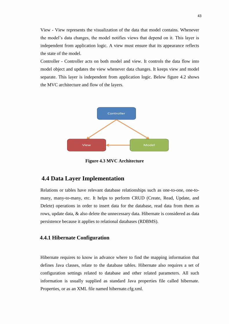
4.3 MVC Architecture
Model–View–Controller (MVC) was the architecture used to develop the system.
MVC is a software architectural pattern for implementing user interfaces. It divides a
given software application into three interconnected parts, so as to separate internal
representations of information from the ways that information is presented to or
accepted from the user. MVC is a most applying design pattern because of its
flexibility & other central usages. It is reusable & expressive that allows more
readable & mobile.
Model - Model represents an object or java POJO carrying data. It can also have
logic to update controller if its data changes. This layer is independent from other
system layers such as, View and Controller. It also governs the rules to access the
data objects and perform any kind of operation on them. It knows all details about
data which needed to be displayed.
43
View - View represents the visualization of the data that model contains. Whenever
the model’s data changes, the model notifies views that depend on it. This layer is
independent from application logic. A view must ensure that its appearance reflects
the state of the model.
Controller - Controller acts on both model and view. It controls the data flow into
model object and updates the view whenever data changes. It keeps view and model
separate. This layer is independent from application logic. Below figure 4.2 shows
the MVC architecture and flow of the layers.
Figure 4.3 MVC Architecture
4.4 Data Layer Implementation
Relations or tables have relevant database relationships such as one-to-one, one-to-
many, many-to-many, etc. It helps to perform CRUD (Create, Read, Update, and
Delete) operations in order to insert data for the database, read data from them as
rows, update data, & also delete the unnecessary data. Hibernate is considered as data
persistence because it applies to relational databases (RDBMS).
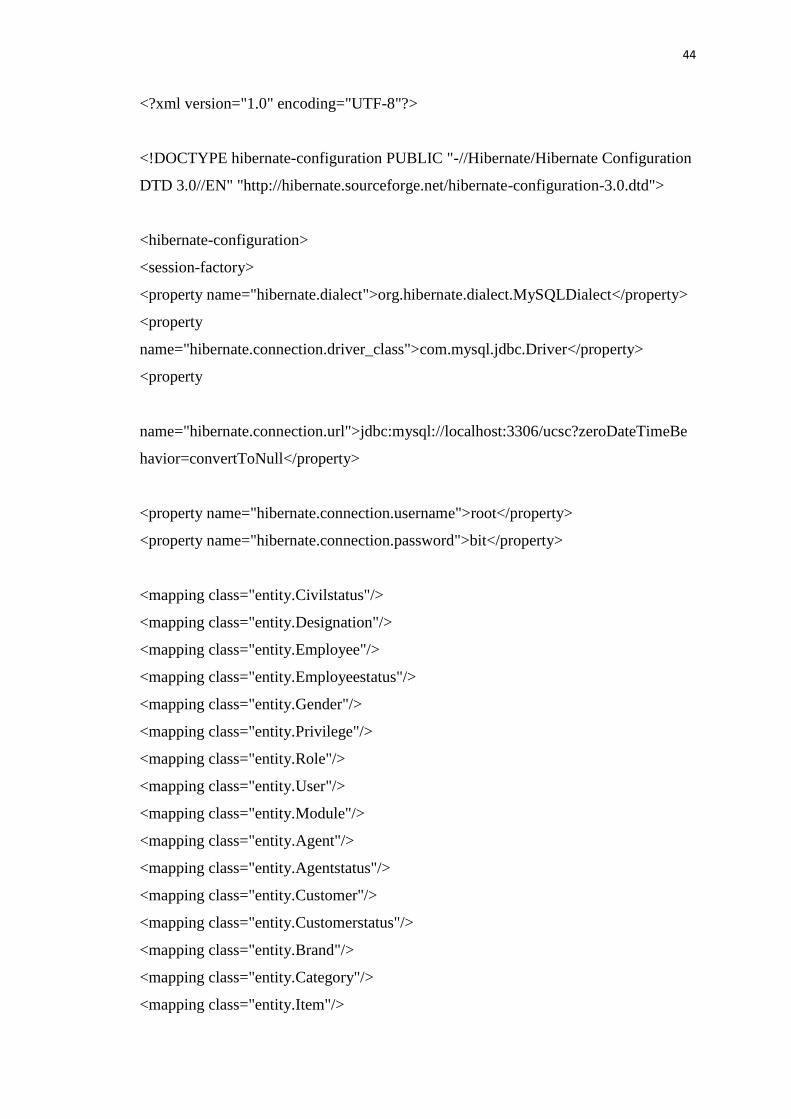
4.4.1 Hibernate Configuration
Hibernate requires to know in advance where to find the mapping information that
defines Java classes, relate to the database tables. Hibernate also requires a set of
configuration settings related to database and other related parameters. All such
information is usually supplied as standard Java properties file called hibernate.
Properties, or as an XML file named hibernate.cfg.xml.
44
<?xml version="1.0" encoding="UTF-8"?>
<!DOCTYPE hibernate-configuration PUBLIC "-//Hibernate/Hibernate Configuration
DTD 3.0//EN" "http://hibernate.sourceforge.net/hibernate-configuration-3.0.dtd">
<hibernate-configuration>
<session-factory>
<property name="hibernate.dialect">org.hibernate.dialect.MySQLDialect</property>
<property
name="hibernate.connection.driver_class">com.mysql.jdbc.Driver</property>
<property
name="hibernate.connection.url">jdbc:mysql://localhost:3306/ucsc?zeroDateTimeBe
havior=convertToNull</property>
<property name="hibernate.connection.username">root</property>
<property name="hibernate.connection.password">bit</property>
<mapping class="entity.Civilstatus"/>
<mapping class="entity.Designation"/>
<mapping class="entity.Employee"/>
<mapping class="entity.Employeestatus"/>
<mapping class="entity.Gender"/>
<mapping class="entity.Privilege"/>
<mapping class="entity.Role"/>
<mapping class="entity.User"/>
<mapping class="entity.Module"/>
<mapping class="entity.Agent"/>
<mapping class="entity.Agentstatus"/>
<mapping class="entity.Customer"/>
<mapping class="entity.Customerstatus"/>
<mapping class="entity.Brand"/>
<mapping class="entity.Category"/>
<mapping class="entity.Item"/>

45
<mapping class="entity.Itemstatus"/>
<mapping class="entity.Subcategory"/>
<mapping class="entity.Customerorder"/>
<mapping class="entity.Orderitems"/>
<mapping class="entity.Orderstatus"/>
<mapping class="entity.Importitems"/>
<mapping class="entity.Importorder"/>
<mapping class="entity.Importstatus"/>
</session-factory>
</hibernate-configuration>
Code 4.1 hibernate.cfg.xml
4.4.2 Create Java Entities
An entity (class) is a lightweight persistence domain object. Typically an entity
represents a table in a relational database, and each entity instance corresponds to a
row in that table. The primary programming artifact of an entity is the entity class,
although entities can use helper classes. Java classes whose objects or instances will
be stored in database tables are called persistent classes in Hibernate.
@Entity
@Table(name = "agent")
@XmlRootElement
@NamedQueries
({
@NamedQuery(name = "Agent.findAll", query = "SELECT a FROM
Agent a"),
@NamedQuery(name = "Agent.findById", query = "SELECT a FROM Agent
a WHERE a.id = :id"), @NamedQuery(name = "Agent.findByName", query =
"SELECT a FROM Agent a WHERE a.name = :name")
})

46
public class Agent implements Serializable {
@OneToMany(cascade = CascadeType.ALL, mappedBy = "agentId")
private List<Importorder> importorderList;
@JoinColumn(name = "agentstatus_id", referencedColumnName =
"id")
@ManyToOne(optional = false)
private Agentstatus agentstatusId;
private static final long serialVersionUID = 1L;
@Id
@GeneratedValue(strategy = GenerationType.IDENTITY)
@Basic(optional = false)
@Column(name = "id")
private Integer id;
@Column(name = "name")
Agent.java
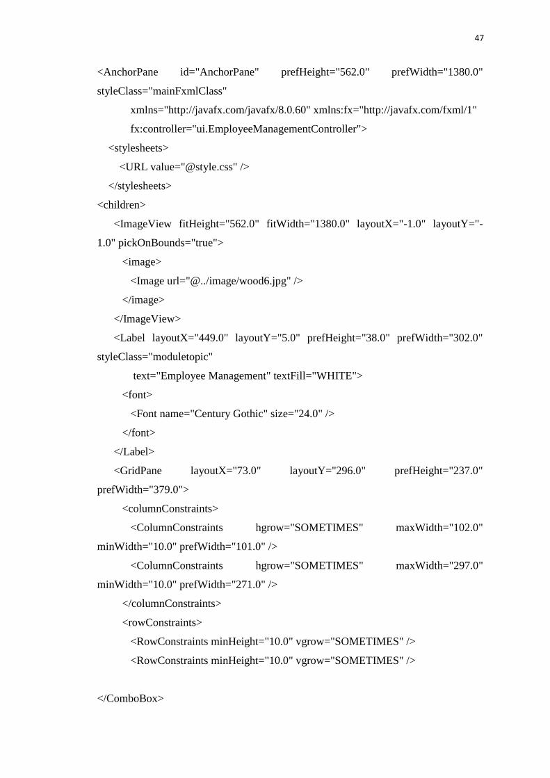
4.5 Interface Layer Implementation
Interface is the user view which user interacts. It facilitates user to do necessary
operations and modifications to forms and views. JavaFX Scene Builder 2.0 was used
to create interfaces in the system. Drag and drop functionalities used to create
controllers relevant to forms. When developer adds a new component to the form the
scene builder automatically create the xml document to that. This feature is a great
help to developers to save their developing time.
The following code fragment shows the auto generated xml document for Company
employee interface.
47
<AnchorPane id="AnchorPane" prefHeight="562.0" prefWidth="1380.0"
styleClass="mainFxmlClass"
xmlns="http://javafx.com/javafx/8.0.60" xmlns:fx="http://javafx.com/fxml/1"
fx:controller="ui.EmployeeManagementController">
<stylesheets>
<URL value="@style.css" />
</stylesheets>
<children>
<ImageView fitHeight="562.0" fitWidth="1380.0" layoutX="-1.0" layoutY="-
1.0" pickOnBounds="true">
<image>
<Image url="@../image/wood6.jpg" />
</image>
</ImageView>
<Label layoutX="449.0" layoutY="5.0" prefHeight="38.0" prefWidth="302.0"
styleClass="moduletopic"
text="Employee Management" textFill="WHITE">
<font>
<Font name="Century Gothic" size="24.0" />
</font>
</Label>
<GridPane layoutX="73.0" layoutY="296.0" prefHeight="237.0"
prefWidth="379.0">
<columnConstraints>
<ColumnConstraints hgrow="SOMETIMES" maxWidth="102.0"
minWidth="10.0" prefWidth="101.0" />
<ColumnConstraints hgrow="SOMETIMES" maxWidth="297.0"
minWidth="10.0" prefWidth="271.0" />
</columnConstraints>
<rowConstraints>
<RowConstraints minHeight="10.0" vgrow="SOMETIMES" />
<RowConstraints minHeight="10.0" vgrow="SOMETIMES" />
</ComboBox>

48
<DatePicker fx:id="dtpAssign" onAction="#dtpAssignAP" prefHeight="25.0"
prefWidth="308.0" promptText="Select Assigned Date" GridPane.columnIndex="1"
GridPane.rowIndex="4" />
<ComboBox fx:id="cmbEmployeestatus"
onAction="#cmbEmployeestatusAP" prefHeight="25.0" prefWidth="304.0"
promptText="Select Employee Status" GridPane.columnIndex="1"
GridPane.rowIndex="5">
<items>
<FXCollections fx:factory="observableArrayList">
<String fx:value="Item 1" />
<String fx:value="Item 2" />
<String fx:value="Item 3" />
</FXCollections>
</items>
</ComboBox>
<Label styleClass="formfield" text="Mobile" textFill="WHITE" />
<Label prefHeight="17.0" prefWidth="29.0" styleClass="formfield"
text="Land" textFill="WHITE" GridPane.rowIndex="1" />
<Label styleClass="formfield" text="Email" textFill="WHITE"
GridPane.rowIndex="2" />
<TextField fx:id="txtMobile" onKeyReleased="#txtMobileKR"
prefHeight="25.0" prefWidth="257.0" promptText="Enter Mobile Number Here"
GridPane.columnIndex="1" />
<TextField fx:id="txtLand" onKeyReleased="#txtLandKR" prefHeight="25.0"
prefWidth="272.0" promptText="Enter Land Number Here"
GridPane.columnIndex="1" GridPane.rowIndex="1" />
<TextField fx:id="txtEmail" onKeyReleased="#txtEmailKR"
prefHeight="25.0" prefWidth="272.0" promptText="Enter Email Address Here"
GridPane.columnIndex="1" GridPane.rowIndex="2" />
</children>
</GridPane>
<GridPane layoutX="710.0" layoutY="111.0" prefHeight="121.0"
prefWidth="348.0">
<columnConstraints>

49
<ColumnConstraints hgrow="SOMETIMES" maxWidth="106.0"
minWidth="10.0" prefWidth="99.0" />
<ColumnConstraints hgrow="SOMETIMES" maxWidth="279.0"
minWidth="10.0" prefWidth="249.0" />
</columnConstraints>
<rowConstraints>
<RowConstraints minHeight="10.0" vgrow="SOMETIMES" />
Employee.fxml
Following code segment shows the controller class of the company employee
interface.
@Override
public void initialize(URL url, ResourceBundle rb) {
initial = Style.initial;
valid = Style.valid;
invalid = Style.invalid;
update = Style.updated;
loadForm();
loadTable();
}
private void loadForm() {
employee = new Employee();
oldEmployee = null;
cmbGender.setItems (GenderDao.getAll());
cmbGender.getSelectionModel().clearSelection();
cmbCivilstatus.setItems(CivilstatusDao.getAll());
cmbCivilstatus.getSelectionModel().clearSelection();

50
cmbDesignation.setItems(DesignationDao.getAll());
cmbDesignation.getSelectionModel().clearSelection();
cmbEmployeestatus.setItems(EmployeestatusDao.getAll());
cmbEmployeestatus.getSelectionModel().select(0);
cmbEmployeestatus.setDisable(true);
employee.setEmployeestatusId(cmbEmployeestatus.getSelectionModel().getSelectedIt
em());
txtName.setText("");
txtAddress.setText("");
txtNic.setText("");
txtMobile.setText("");
txtLand.setText("");
txtEmail.setText("");
dtpDob.setValue(null);
dtpAssign.setDisable(true);
dtpAssign.setValue(LocalDate.parse(new SimpleDateFormat("yyyy-MM-
dd").format(new Date())));
Date assign = java.sql.Date.valueOf(dtpAssign.getValue());
employee.setAssigndate(assign);
imgPhoto.setImage(new Image("/image/user1.png"));
photoSelected = false;
dissableButtons(false, false, true, true);
setStyle(initial); }
private void dissableButtons(boolean select, boolean insert, boolean update, boolean
delete) {
btnAdd.setDisable(insert);
btnUpdate.setDisable(update);
btnDelete.setDisable(delete);
}
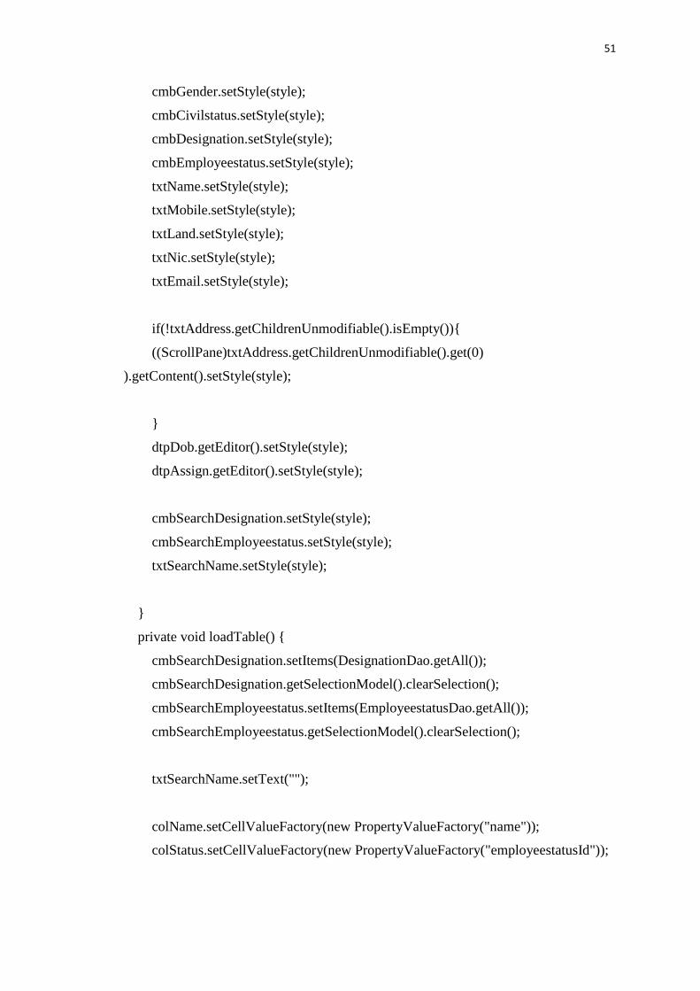
private void setStyle(String style) {
51
cmbGender.setStyle(style);
cmbCivilstatus.setStyle(style);
cmbDesignation.setStyle(style);
cmbEmployeestatus.setStyle(style);
txtName.setStyle(style);
txtMobile.setStyle(style);
txtLand.setStyle(style);
txtNic.setStyle(style);
txtEmail.setStyle(style);
if(!txtAddress.getChildrenUnmodifiable().isEmpty()){
((ScrollPane)txtAddress.getChildrenUnmodifiable().get(0)
).getContent().setStyle(style);
}
dtpDob.getEditor().setStyle(style);
dtpAssign.getEditor().setStyle(style);
cmbSearchDesignation.setStyle(style);
cmbSearchEmployeestatus.setStyle(style);
txtSearchName.setStyle(style);
}
private void loadTable() {
cmbSearchDesignation.setItems(DesignationDao.getAll());
cmbSearchDesignation.getSelectionModel().clearSelection();
cmbSearchEmployeestatus.setItems(EmployeestatusDao.getAll());
cmbSearchEmployeestatus.getSelectionModel().clearSelection();
txtSearchName.setText("");
colName.setCellValueFactory(new PropertyValueFactory("name"));
colStatus.setCellValueFactory(new PropertyValueFactory("employeestatusId"));

52
Employee Controller.java
The following CSS segment has used to style the Company interface
public class Style {
public static String valid = "-fx-background-color:lightgreen;";
public static String invalid = "-fx-background-color:pink;";
public static String updated = "-fx-background-color:khaki;";
public static String initial = "-fx-background-color:white;";
}
Code 4.4: Company.css
4.6 Control Layer Implementation
Control layer is the link between data layer & the interface layer. Here logical
concept is, Parse a user request (i.e., "read" it), validate the user request (i.e., assure it
on forms to application's requirements), determine what the user is trying to do
(based on form elements), obtain data from the Model (if necessary) to include in
response to user, select the next View the client should see.
The sequencing of calls to the Model (business-logic layer), and/or the sequencing of
views and required input from the user defines the application's workflow. Workflow
is thus defined in the Controller layer of the application.
4.6.1 Hibernate Sessions
The Session Factory is the concept that is a single data store and thread safe. Because
of this feature, many threads can access this concurrently and the sessions are
requested, and also the cache that is immutable of compiled mappings for a specific
database. A Session Factory will be built only at the time of its startup. In order to
access it in the application code, it should be wrapped in singleton. This wrapping
makes the easy accessibility to it in an application code.

53
4.6.2 Data Access Objects (DAO)
A data access object (DAO) is an object that provides an abstract interface to some
type of database or persistence mechanism, providing some specific operations
without exposing details of the database. It provides a mapping from application calls
to the persistence layer. This isolation separates the concerns of what data accesses
the application needs, in terms of domain-specific objects and data types (the public
interface of the DAO), and how these needs can be satisfied with a specific DBMS,
database schema, etc. (the implementation of the DAO). Following codes shows the
summery for Company Dao class.
public class EmployeeDao {
public static ObservableList<Employee> getAll(){
return CommonDao.select("Employee.findAll");
}
public static void add(Employee employee) {
CommonDao.insert(employee);
}
public static Employee getById(Integer id) {
HashMap hmap = new HashMap();
hmap.put("id", id);
ObservableList<Employee> list =
CommonDao.select("Employee.findById",hmap);
return list.isEmpty() ? null : list.get(0);
}
public static void update(Employee employee) {
CommonDao.update(employee);
}
public static void delete(Employee oldEmployee) {

54
CommonDao.delete(oldEmployee);
}
public static ObservableList<Employee> getAllByName(String name) {
HashMap hmap = new HashMap();
hmap.put("name", name + "%");
return CommonDao.select("Employee.findAllByName",hmap); }
public static ObservableList<Employee> getAllByDesignation(Designation
designation) {
HashMap hmap = new HashMap();
hmap.put("designation", designation);
return CommonDao.select("Employee.findAllByDesignation", hmap);
EmployeeDao.java
4.7 Reused Code Modules
Some tutorials were referred from the internet to learn Java, JavaFX and Hibernate.
When developing this system I have used few libraries and classes for Netbeans IDE
because I wanted to add more functionality to the system. Client’s requirement also
driven me to use some external libraries which do not exist as built in libraries in
Netbeans IDE.
I have used Jasper Report API to generate reports of the system. Because of that
system facilitates report generating task for users when they need reports to analyze
their business and achieve goals. Also I have used hibernate ORM to build up
database connection of my system [11].
Some of the codes of HibernateUtil class describes below.
package dao;
import org.hibernate.cfg.AnnotationConfiguration;
import org.hibernate.SessionFactory;

55
public class HibernateUtil {
private static final SessionFactory sessionFactory;
static {
try {
// Create the SessionFactory from standard (hibernate.cfg.xml)
// config file.
sessionFactory = new
AnnotationConfiguration().configure().buildSessionFactory();
} catch (Throwable ex) {
// Log the exception.
System.err.println("Initial SessionFactory creation failed." + ex);
throw new ExceptionInInitializerError(ex);
}
}
public static SessionFactory getSessionFactory() {
return sessionFactory; }}
Code 4.6: HibernateUtil.java

56
CHAPTER 5 : EVALUATION
In software project management software testing, software engineering, verification
and validation (V&V) is the process of checking that a software system meets
specifications and that it fulfills its intended purpose. It may also be referred to
as software quality control. It is normally the responsibility of software testers as part
of the software development lifecycle. In simple terms, software verification is:
"Assuming we should build X, does our software achieve its goals without any bugs
or gaps?" On the other hand, software validation is: "Was X what we should have
built? Does X meet the high level requirements?"[11]
5.1. Test Strategies
Imports and inventory management system for Paramount Impex (Pvt) ltd was tested
according to the following test plan in order to ensure the products reliability.
5.1.1. Unit Testing
The smallest piece/the component of the system is called a unit. In object oriented
Programming (OOP) it can be a method or a class. Unit testing was done while
implementing the system to check whether the source code are accurate and working
properly.
5.1.2. Integration Testing
The integration testing process is carried out to ensure that the combined units are
working properly & gives the expected results. This testing was carried out before the
system validation and also after unit testing.

57
5.1.3. System Testing
System testing is performed on the entire system in the context of a Functional
Requirement Specification(s) (FRS) and/or a System Requirement Specification
(SRS). System testing tests not only the design, but also the behavior and even the
believed expectations of the customer. It is also intended to test up to and beyond the
bounds defined in the software/hardware requirements specification(s) [12]
5.2. Test Cases
Test No Test Description Expected Results Status
1 Go to Business Activity menu
and select Customer
Management
Add Customer internal
frame shows in the Desktop
Pane
2 Add registered Customer Error message will indicate
the Customer is already
registered.
3 Insert Character in the “Contact
Number”
Text field indicated in red
and will not allow to enter
4 Add new customer with empty
fields
Error message displays to
fill required details to add
customer
5 Add news customer with all
details
System will successfully
add the customer and will
be displayed in the table.
6 Entering invalid email address Text field indicated in red
and will not allow to enter
7 Enter numbers in the name
field
Text field indicated in red
and will not allow to enter
Test case for Customer Form
Test No Test Description Expected Results Status
1 Go to Administrative Activity
menu and select Employee
Management
Employee internal frame
shows in the Desktop Pane
2 Close Employee form Shows the main window

58
3 Add new employee with all
details
System will ask for
confirmation and adds the user
to the system
Add existing employee System will indicate an error
message the employee is
already in the system
3 Insert Character in the “Contact
Number”
Text field indicated in red and
will not allow to enter
4 Add new employee with empty
fields
Error message displays to fill
required details to add
customer
5 Enter Name with all simple
letters
System will validate the field
and turn red since the first
letter of the name must be
capital
6 Entering invalid email address Text field indicated in red and
will not allow to enter
7 Enter numbers in the name field Text field indicated in red and
will not allow to enter
Test case for Employee Form
Test No Test Description Expected Results Status
1 Go to Business Activity menu
and select Agent Management
Add Agent internal frame
shows in the Desktop Pane
2 Add registered Agent Error message will indicate
the Agent is already
registered.
3 Insert Character in the “Contact
Number”
Text field indicated in red
and will not allow to enter
4 Add new Agent with empty
fields
Error message displays to
fill required details to add
agent
5 Add news customer with all
details
System will successfully
add the customer and will
be displayed in the table.
6 Entering invalid email address Text field indicated in red
and will not allow to enter
7 Enter numbers in the name
field
Text field indicated in red
and will not allow to enter
Test case for Agent Form

59
5.3 Use Acceptance Testing
User acceptance testing (UAT) consists of a process of verifying that a solution
works for the user.[6] It is not system testing (ensuring software does not crash and
meets documented requirements), but rather ensures that the solution will work for
the user (i.e., tests that the user accepts the solution); software vendors often refer to
this as "Beta testing".
The UAT acts as a final verification of the required business functionality and proper
functioning of the system, emulating real-world conditions on behalf of the paying
client or a specific large customer. If the software works as required and without
issues during normal use, one can reasonably extrapolate the same level of stability in
production.[8]
User tests, usually performed by clients or by end-users, do not normally focus on
identifying simple cosmetic problems such as spelling errors, nor
on showstopper defects, such as software crashes; testers and developers identify and
fix these issues during earlier unit testing, integration testing, and system testing
phases.
In industry, a common UAT is a factory acceptance test (FAT). This test takes place
before installation of the equipment. Most of the time testers not only check that the
equipment meets the specification, but also that it is fully functional. A FAT usually
includes a check of completeness, a verification against contractual requirements, a
proof of functionality (either by simulation or a conventional function test) and a
final inspection. [13]

60
Figure User Satisfaction
0
2
4
6
8
10
12
14
System Usability System Featuresand Facilities
Data Accuracy andTracking
Interface Designs Suportive inDicision Making
Overall Feedback of 12 Employees
All users Positive Feedback

61
CONCLUSION
6.1 Introduction
Paramount Impex (Pvt) Ltd is a fast growing company in the industry right now
when it comes to importing Hardware equipment. Since the world is developing day
to day new construction are been made so the demand for the market and product is
high. If we are to compete with such advanced and challenging a company should
have a unique stretch to lead the market. Therefore the main requirements from the
user was the efficiency and reliability of the system.
The company already had a process which were running stable but they had the
potentiality to reach more. So with this system according to the feedback calculated
they are pleased that most of their redundant tasks have been systemized and
automated. Also the efficiency and the work enthusiasm of the user have been
motivated.
Certain features from the system, Notifications were much appreciated by the users
and since all the transaction were easy to track and update through the system the
managers were much please. The report generation, Payment management process
were key areas from the system said by the Finance Team.
6.2 Lessons Learnt
This has been a great opportunity for me to bring into action the skills and knowledge
I have acquired for the past years throughout the degree program. Getting to know
the Art of programming and the skills of gathering the right information turned into
code is an achievement as I believe. Learning SQL, Hibernate and JavaFX has been a
great strength for through this project.
Apart from the skills and tools I have learned more about communication, building
good relationship and being able to express and share knowledge among the users are
vital. Whenever a problem arises the proper way to bring up and resolve with the
right communication are some of the best things I have learned by this project. Also I

62
am thankful I had received great supervisor to guide me the right path right through
from the very beginning of the project.
6.3 Future Improvements
As further improvements following features are planning to add to the newly built
system.
Web based solution for the system will be introduced for ease of connecting
newly constructed branches of Paramount Impex (Pvt) Ltd.
Allow customers to make Orders online where ever they are located and the
higher management could access data online.
System will be expanded in future to manage attendance and payroll of
employees.
Introduced system has been developed with the ability of any enlargements easily
such as adding more functions to the system.
63
REFERENCE
[1] "The System is shipping and order management solution.." [Online].
Available: http://www.capterra.com/order/software/spotlight/128322/ShipStation..
[2] "The waterfall model was the first Process Modal to be introduced." [Online].
Available: https://www.tutorialspoint.com/sdlc/sdlc_waterfall_model.htm.
[3] "RAD Model distributes the analysis, design,nuild prototypes.." [Online].
Available: https://en.wikipedia.org/wiki/Systems_design.
[4] "OOAD is a popular technical approcah to Analyize, Design.." [Online].
Available: https://en.wikipedia.org/wiki/Database_design.
[5] "MySQL is a Relational Database Management System. In July 2013.. " [Online].
Available: https://en.wikipedia.org/wiki/MySQL.
[6] Java is a general purpose computer programming language that is concurrent.." [Online].
Available: https://en.wikipedia.org/wiki/Java_(programming_language).
[7] "The official MySQL workbench is a free integrated environment.." [Online].
Available: https://en.wikipedia.org/wiki/MySQL.
[8] "JavaFX scene bbuilder is a visual layout tool that lets users…" [Online].
Available:http://www.oracle.com/technetwork/java/javase/downloads/javafxscenebuilder-
info-2157684.html.
[9] "Visual Paradigam for UML (VP-UML) is a UML CASE Tool.." [Online].
Available:http://www.dpi.ufv.br/projetos/geoprofile/tutoriais/Visual_Paradigm_for_UML_
Tutorial_english.pdf..
[10] "Hibernate ORM is an Object relational mapping framework.." [Online].
Available: https://en.wikipedia.org/wiki/Hibernate_(framework).
[11] "Assume we should build X does our software achieve its goal.." [Online].
Available: https://en.wikipedia.org/wiki/Software_verification_and_validation.
[12] "System tesing is performedon the entire system in the context of functional.." [Online].
Available: https://en.wikipedia.org/wiki/System_testing.
[13] "In the industry a common UAT is a factory acceptence test.(FAT)" [Online].
Available: https://en.wikipedia.org/wiki/Acceptance_testing#User_acceptance_testing.
[14] "Verification and Validation is a process (V & V) of checking that a softeware. " [Online].
Available: https://en.wikipedia.org/wiki/Software_verification_and_validation.
[15] " In the industry a common UAT is a factory acceptence test." [Online].
Available: https://en.wikipedia.org/wiki/Acceptance_testing#User_acceptance_testing.

64
APPENDIX A: SYSTEM
DOCUMENTATION
HARDWARE AND SOFTWARE CONFIGURATION REQUIREMENTS
This section contains steps about installation, Hardware & software configuration
requirements which important to users, administrators or anyone who wish to
continue this project.
Below table A.1 shows the hardware and software requirements which needed to
setup the system in client’s machine.
Table 1.1: Hardware Requirements for client application
Table 1.1: Software Requirements for client application
Hardware Equipment Recommended Requirement level
Processor Pentium 4 (2.5Ghz) or above
Memory 512MB minimum for Windows XP
1 GB minimum for Windows Vista or
Windows 7
Hard Disk 2GB free space
CD Drive 42x
Screen Resolution 1366*768
Software Requirements Recommended Requirement level
Operating System Windows 7 or above
Java JDK 1.7.0 or above
DBMS MySQL Server 5.5 or above
DBMS Tools MySQL Query Browser 5.0 or above

65
SOFTWARE INSTALLATION AND CONFIGERATION
Install Java Run Time on Client Machine
Installation progress of JVM (Step1)
Installation progress of JVM (Step 2)-Select Optional features and click next

66
Installation progress of JVM (Step 3)
Installation progress of JVM (Step 4)-Select destination folder to install

67
Installation progress of JVM (Step 5)
Installation progress of JVM (Step 6) "click Finish to complete the installation"
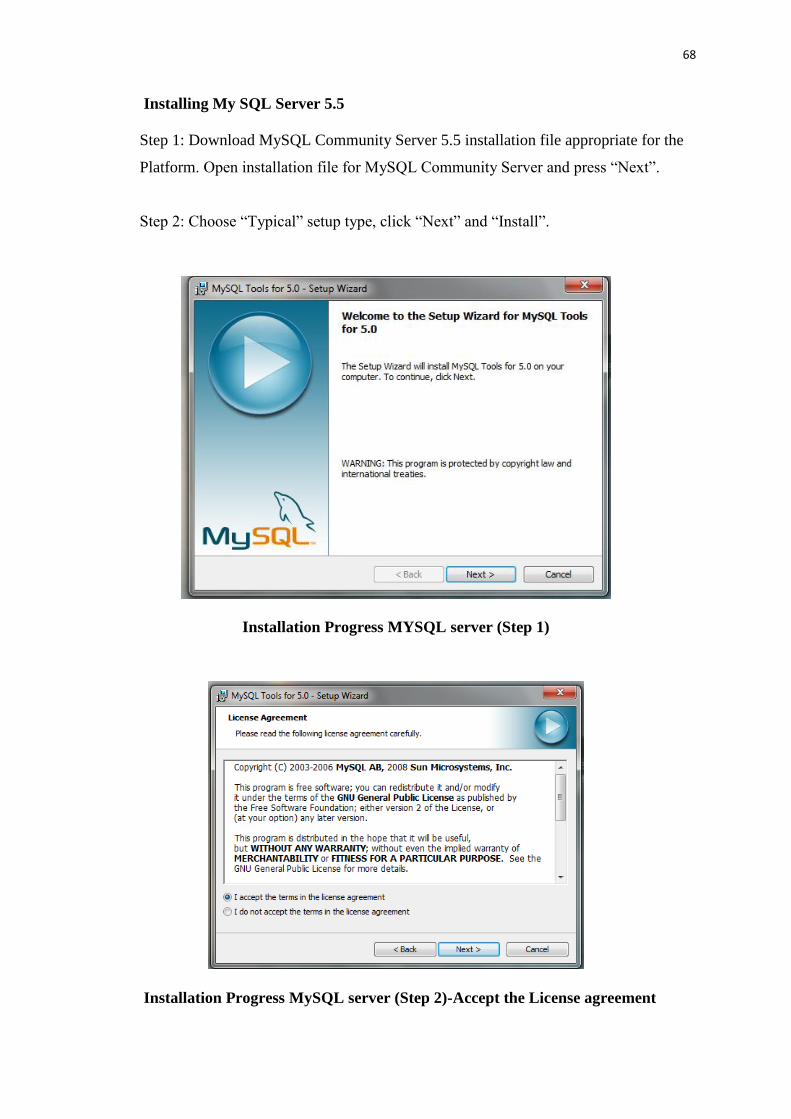
68
Installing My SQL Server 5.5
Step 1: Download MySQL Community Server 5.5 installation file appropriate for the
Platform. Open installation file for MySQL Community Server and press “Next”.
Step 2: Choose “Typical” setup type, click “Next” and “Install”.
Installation Progress MYSQL server (Step 1)
Installation Progress MySQL server (Step 2)-Accept the License agreement

69
Step 3: Choose “Typical” setup type, click “Next” and “Install”.
Step 4: Click “Install” to begin the installation.
Installation Progress MySQL server (Step 3)
Installation Progress MySQL server (Step 4)

70
Step 5: After installation process is completed, check “Launch the MySQL Instance
Configuration Wizard” and click “Finish”.
Step 6: Click “Next” when “Configuration Wizard” appears.
Installation Progress MySQL server (Step 5)
Installation Progress MySQL server (Step 6)

71
Step 7: Choose “Standard Configuration” and click “Next”.
Step 8: Check “Install as Windows Service”, select service name “MySQL”. Check
“Launch the MySQL Server automatically”. Then check “Include Bin Directory in
Windows PATH” and click “Next”.
Installation Progress MySQL Server (Step 7)
Installation Progress MySQL Server (Step 8)

72
Step 9: Check “Modify Security Settings”, Set a new password to the “root” user.
Check “Enable root access from remote machines”. Click “Next” and then
“Execute”.
Step 10: After configuration process is completed click “Finish”.
Installation Progress MySQL Server (Step 9)
Installation Progress MySQL Server (Step 10)

73
Installing Microsoft SQL Query Browser
Installation Progress MySQL Query Browser (Step 1) - "Click Next"
Installation Progress MySQL Query Browser (Step 2)-Accept License Agreement

74
Installation Progress MySQL Query Browser (Step 3)-Select destination folder and
click "Next"
Installation Progress MySQL Query Browser (Step 4)-Click "Finish" to complete the
wizard

75
Open MySQL Administrator & Insert server host, port & the user name as given above
& enter the given password (Step5).
This section contains steps about installation, Hardware & software configuration
requirements which important to users, administrators or anyone who wish to
continue this project.

76
To restore the database create a new database then select restore database & last set
database to system database (Step6)
A.1.4 Inventory Management System
After setting up the database,
Select from device
Click Add & Browse the Imports and Inventory Management System file from CD
Run the Paramount Impex.exe file located in CD.

77
APPENDIX B: DESIGN
DOCUMENTATION
B.1 Activity diagram
B.1.1 Activity diagram for user login
Figure B.1.1 Activity Diagram for User Login.

78
Figure B.1.2 Activity diagram on User Account Creation.

79
Figure B.1.3 Activity diagram on making a Customer Order.

80
Figure B.1.4 Activity diagram on making an Import Order.

81
B.2 Sequence diagrams
A sequence diagram shows object interactions arranged in time sequence. It shows
the objects and classes contain in the scenario and the sequence of messages
exchanged between the objects. Below figure B.3 shows the sequence diagram for
report generation of the system.
Figure B.2 Sequential Diagram Report Generation

82
B.3 Use case Diagram with Detailed information
Use case diagram for creating a user account.
Figure B.3.1: Add user account
Use case diagram for adding privileges to user accounts.
Figure B.3.12: Add privileges to user accounts

83
Use case diagram for creating a Customer Order.
Figure B.3.3: Creating a Customer Order
Use case diagram for creating an Agent Import Order.
Figure B.3.4 Creating an Agent Import Order
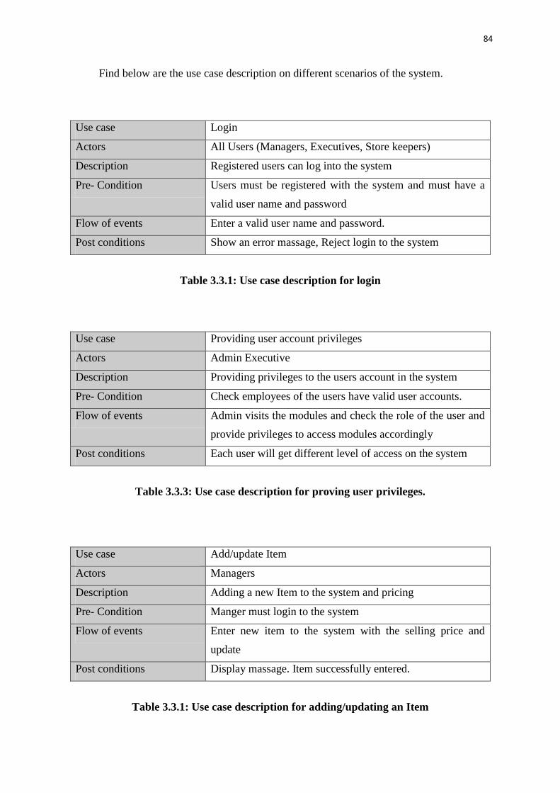
84
Find below are the use case description on different scenarios of the system.
Use case Login
Actors All Users (Managers, Executives, Store keepers)
Description Registered users can log into the system
Pre- Condition Users must be registered with the system and must have a
valid user name and password
Flow of events Enter a valid user name and password.
Post conditions Show an error massage, Reject login to the system
Table 3.3.1: Use case description for login
Use case Providing user account privileges
Actors Admin Executive
Description Providing privileges to the users account in the system
Pre- Condition Check employees of the users have valid user accounts.
Flow of events Admin visits the modules and check the role of the user and
provide privileges to access modules accordingly
Post conditions Each user will get different level of access on the system
Table 3.3.3: Use case description for proving user privileges.
Use case Add/update Item
Actors Managers
Description Adding a new Item to the system and pricing
Pre- Condition Manger must login to the system
Flow of events Enter new item to the system with the selling price and
update
Post conditions Display massage. Item successfully entered.
Table 3.3.1: Use case description for adding/updating an Item

85
Below table 3.3.2 shows the use case description for adding customer details to the
system. It describes the actors, pre-conditions, post conditions and flow of the event
of the adding customer details use case.
Use case Add Customer
Actors Customer Executive
Description Adding details about new customers
Pre- Condition User must login to the system
Flow of events Enter new customers and save
Post conditions New records available in the company database
Table 3.3.2: Use case description for add customer details
Below table 3.3.2 shows the use case description for adding agent details to the
system. It describes the actors, pre-conditions, post conditions and flow of the event
of the adding customer details use case.
Use case Add Importer
Actors Imports Executive
Description Adding details about new Importers
Pre- Condition Uses must login to the system
Flow of events Enter new importers and save
Post conditions New records available in the company database
Table 3.3.2: Use case description for add importers details
Below table 3.3.3 shows the use case description for adding a customer order to the
system. It describes the actors, pre-conditions, post conditions and flow of the event
of the adding purchase details use case. Import Executive is the actor of the use case.

86
Use case Add Customer order
Actors Customer Executive
Description Adding details about an order from Customer
(Local Company)
Pre- Condition Customer should request their relevant order
Flow of events User fills the forms generated by the system.
Post conditions Create the order sheet
Table 3.3.3: Use case description for add customer order details
Below table 3.3.3 shows the use case description for adding an import order to the
system. It describes the actors, pre-conditions, post conditions and flow of the event
of the adding purchase details use case. Import Executive is the actor of the use case.
Use case Add import order details
Actors Imports Executive
Description Adding details about an order from supplier
(Import agent)
Pre- Condition Agent should supply their relevant order
Flow of events User fills the forms generated by the system.
Post conditions Create the order sheet
Table 3.3.3: Use case description for add import order details

87
B.4 Database Design
Structure of Item Table in database is given in Figure B.4.1
Structure of Employee Table in database is given in Figure B.4.2

88
Structure of Customer Table in database is given in Figure B.4.3
Structure of Agent Table in database is given in Figure B.4.4
Structure of Customer Order Table in database is given in Figure B.4.5

89
Structure of Agent Order Table in database is given in Figure B.4.6
Structure of Import Items Table in database is given in Figure B.4.7
Structure of User Table in database is given in Figure B.4.8
Structure of User role Table in database is given in Figure B.4.9

90
Structure of Privilege Table in database is given in Figure B.4.10
Structure of Designation Table in database is given in Figure B.4.11
Structure of Designation Table in database is given in Figure B.4.12

91
APPENDIX C: USER
DOCUMENTATION
Login form
Following Figure C.1 shows user login form which allows users to log into the
system. All levels of users can log into the system in one form. When user try to log
into the system check whether this user is valid user or not otherwise system display
error message.
Figure C.1 Login Form
Main Form
All the functions of each and every module can be accessible by users through this
main form. Following figure C.2 shows how main menu looks like.
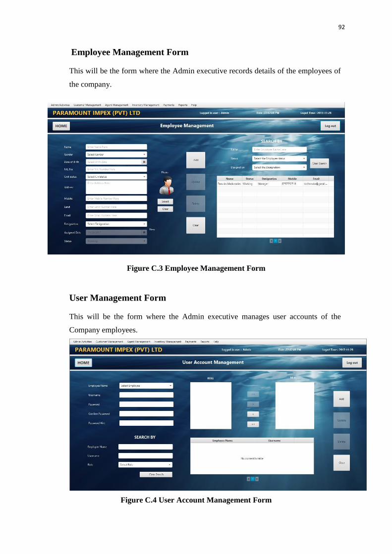
92
Employee Management Form
This will be the form where the Admin executive records details of the employees of
the company.
Figure C.3 Employee Management Form
User Management Form
This will be the form where the Admin executive manages user accounts of the
Company employees.
Figure C.4 User Account Management Form

93
Privilege Management Form
This will be the form where the Admin executive grants access privileges to the user
accounts.
Figure C.5 Privilege Management Form
Item Registry Form
This will be the form where the Company Manager add/update new items of the
company which they would be working on.
Figure C.6 Item Registry Form

94
Agent Management Form
This will be the form where the Import Executive add/update new agents to the
system.
Figure C.7 Agent Management Form
Customer Management From
This will be the form where the Customer Executive add/update new customers to the
system.
Figure C.8 Customer Management Form

95
Customer Order Management From
This will be the form where the Customer Executive add/update new customer orders
to the system.
Figure C.9 Customer Order Form
Import Order Management From
This will be the form where the Import Executive add/update new agent orders to the
system.
Figure C.10. Import Order Management From

96
APPENDIX D: MANAGEMENT
REPORTS
Below shows a simple report of the system which lists out the details of the
employees in the system.
Employee Details report
Below shows a simple monthly report of the list of Import for a particular month
.
Import Details report
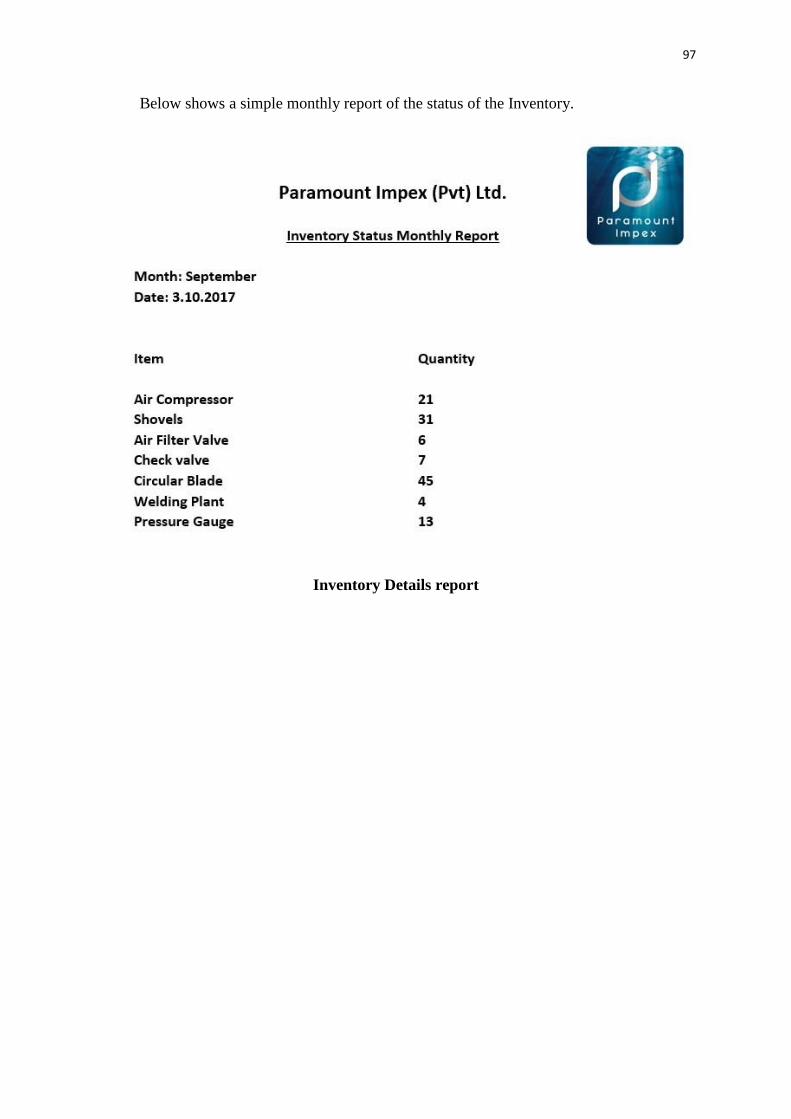
97
Below shows a simple monthly report of the status of the Inventory.
Inventory Details report

98
APPENDIX E: TEST RESULTS
Test Cases of Forms
Test No Test Description Expected Results Status
1 Go to Business Activity menu
and select Customer
Management
Add Customer internal
frame shows in the Desktop
Pane
2 Add registered Customer Error message will indicate
the Customer is already
registered.
3 Insert Character in the “Contact
Number”
Text field indicated in red
and will not allow to enter
4 Add new customer with empty
fields
Error message displays to
fill required details to add
customer
5 Add news customer with all
details
System will successfully
add the customer and will
be displayed in the table.
6 Entering invalid email address Text field indicated in red
and will not allow to enter
7 Enter numbers in the name
field
Text field indicated in red
and will not allow to enter
Test case for Customer Form
Test No Test Description Expected Results Status
1 Go to Administrative Activity
menu and select Employee
Management
Employee internal frame
shows in the Desktop Pane
2 Close Employee form Shows the main window
3 Add new employee with all
details
System will ask for
confirmation and adds the user
to the system
Add existing employee System will indicate an error
message the employee is
already in the system

99
3 Insert Character in the “Contact
Number”
Text field indicated in red and
will not allow to enter
4 Add new employee with empty
fields
Error message displays to fill
required details to add
customer
5 Enter Name with all simple
letters
System will validate the field
and turn red since the first
letter of the name must be
capital
6 Entering invalid email address Text field indicated in red and
will not allow to enter
7 Enter numbers in the name field Text field indicated in red and
will not allow to enter
Test case for Employee Form
Test No Test Description Expected Results Status
1 Go to Business Activity menu
and select Agent Management
Add Agent internal frame
shows in the Desktop Pane
2 Add registered Agent Error message will indicate
the Agent is already
registered.
3 Insert Character in the “Contact
Number”
Text field indicated in red
and will not allow to enter
4 Add new Agent with empty
fields
Error message displays to
fill required details to add
agent
5 Add news customer with all
details
System will successfully
add the customer and will
be displayed in the table.
6 Entering invalid email address Text field indicated in red
and will not allow to enter
7 Enter numbers in the name
field
Text field indicated in red
and will not allow to enter
Test case for Agent Form

100
Test Results for User Acceptance
Different user levels in the company hierarchy consist in Paramount Impex (PVT)
Ltd. The company hierarchy can be identified by referring to figure E.1.
User levels of the Company
External parties that deal with the company are shown in figure E.8.
• Customers
• Agents
User Feedback bar chart gathered by different kind of system users
User Feedback Chart
Above user feedback was gathered based on the interaction with the users by papers,
Interviews, questioners. The beginning was quiet difficult to perform this with the
users since they weren’t much familiar with how it works but eventually they figured
it out well.
Manager
Customer Executive
Imports Executive
Store Keeper
Admin Executive
Finance Executive
Excellent62%
Good23%
Average10%
Weak5%
User Feedback
Excellent Good Average Weak

101
APPENDIX F: CODE LISTING
Major code fragments for anyone who is interested in referring the functionality of
the system are contained in this document. Please refer the CD-ROM for the
complete set of codes for the all code fragments.
Structure of the Code

102
Loading a system Modules
Code on Loading the Form

103
Setting Style for the UI components
Code for loading the Table

104
Code on Add button
Search method

105
Binding Method for Assigned date
Binding Method for Designation
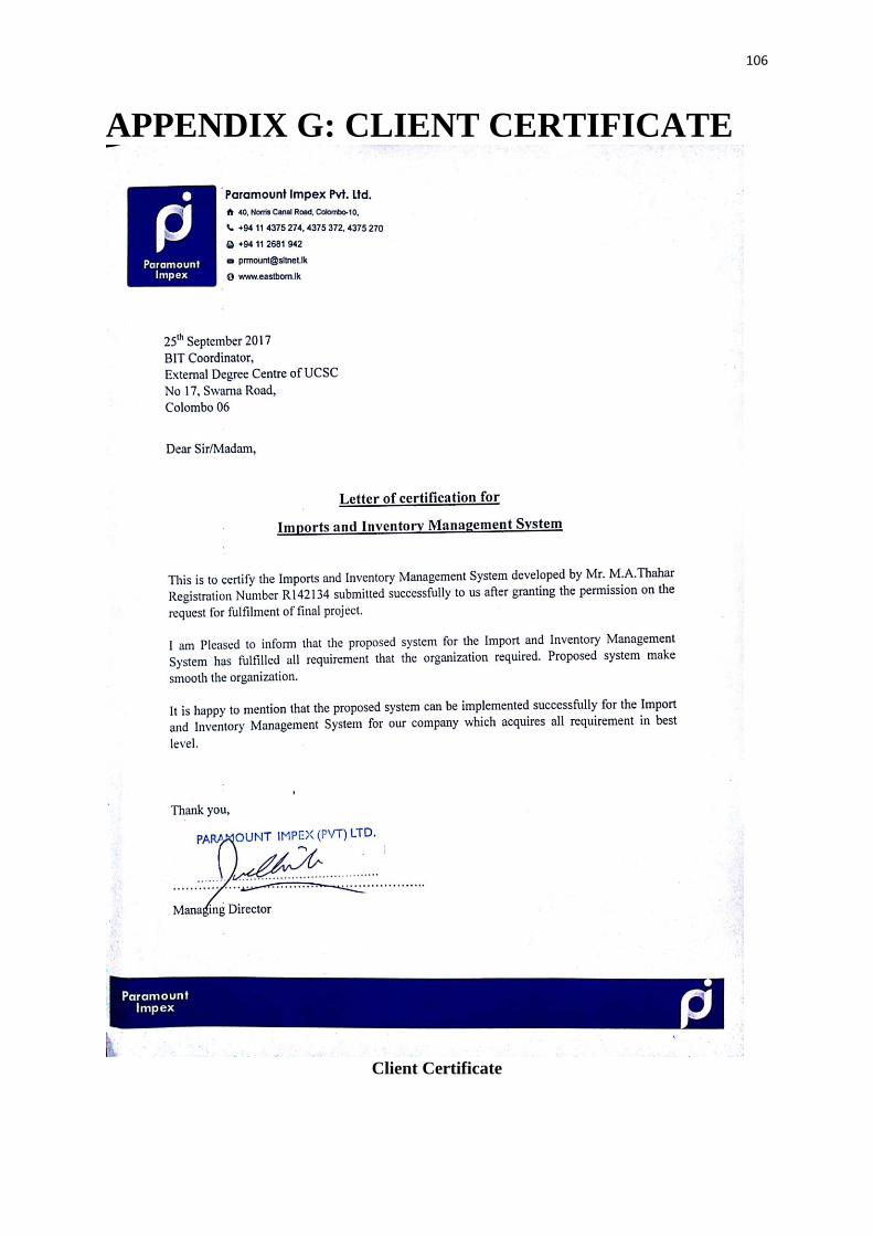
106
APPENDIX G: CLIENT CERTIFICATE
Client Certificate

107
GLOSSARY
Java – Java is a computer programming language which is based on object oriented
concepts.
MySQL - This is a database management system that is freely available. Most developers
and companies use this system for their database needs.
Scrum - That is a software development methodology widely used in the software
development industry. Scrum follows agile development principle.
Sprint - Sprint is the basic unit of development in scrum. It’s time boxed and the duration
is one week to four weeks.
Java FX - is a software platform for creating and delivering desktop applications, as well as
rich internet applications (RIAs) that can run across a wide variety of devices
Hibernate – Hibernate is an Object Relational Mapping tool for Java programming
language.
Estimation – Estimation is rough calculation of value, number or quantity of something.
Dao Class – This means Data Access Object. This provides abstract interact interface for
some databases.
Entity Class – Entity classes represent objects in java programming language and it was
earlier called as POJO Classes.
Stand – alone System – The computer programs those work without using internet
Facilities are called as stand-alone programs.
UML – Unified Modeling Language. This is mostly used in designing computer systems.

108
INDEX
A
Application –16, 18, 30, 31, 32, 33, 34, 35, 36, 41, 42, 44
Analysis –4, 14, 16, 17, 18
Automated System – 1, 16
Activity – 4, 22, 65, 66
B
Browser – 16, 61, 62, 63, 64
Business –1, 2, 3, 5, 6, 8, 10, 11, 13, 16, 17, 18, 24, 29, 33, 41, 43, 50, 80
C
Company – 1, 2, 3, 4, 5, 6, 10, 11, 13, 17, 18, 21, 32, 40, 42, 68, 69, 83
Cost – 3, 6, 13
Customer – 2, 3, 5, 8, 11, 18, 20, 21
D
Design –14, 15, 16, 18, 24, 27, 28, 29, 32, 35, 52
Database –8, 24, 27, 34, 52, 72, 87, 88, 89, 98
Development –1, 4, 10, 13, 14, 15, 16, 17, 18, 29, 30, 32, 43, 98
E
Entity – 4, 34, 38, 76, 77
Employee – 2, 3, 5, 6, 11, 17, 50, 51
Environment – 1, 4, 11, 16, 29, 32, 33, 48, 50, 54
F
Functional requirements – 4, 5, 11, 29, 48
Fact – 4, 5
G
Goal – 13, 43, 48
H Hibernate – 33, 34, 36, 37, 38, 41, 43, 50, 52
I
Information – 1, 2, 3, 5, 12, 13, 16, 35, 36, 43, 45, 54, 82
Implementation –29, 36, 39, 41
Interface –28, 39, 98
J
Jasper Reports – 34, 43
M
Management – 1, 2, 3, 4, 7, 8, 9, 12, 13, 31, 32, 48, 50, 52, 80
Manual – 1, 2, 4, 5, 10, 16, 33, 50
Methodology –13
Model – 7,11,13,19,28,29,31,32,34,40,42,45,58
N
Netbeans – 30, 50
O
Object Oriented – 23, 44
Operations – 3, 16, 18, 36, 39, 42, 77
P
Programming – 31, 33, 38, 98
Purchasing – 16
Q

109
Query browser – 32
R
Requirements – 4, 11, 14, 15, 17, 24, 29, 41, 44, 46, 48, 53
S
Specification – 3, 4
Scope – 29, 31, 35, 43
System 1, 2, 3, 4, 5, 6, 7, 8, 9, 10, 11, 12, 13, 15, 16, 17, 18, 19, 20, 21, 22, 23, 27, 29, 30, 32,
35, 39, 43, 44, 46, 48, 50, 51, 53, 66, 67, 69, 70, 71, 72, 77, 78, 79, 80
T
Transaction – 10, 35, 50, 87, 88, 89
Testing – 4, 14, 43, 44, 48, 52
U
User - 8, 9, 10, 13, 21, 27, 37, 47, 48, 49, 50, 77, 98
Use case – 7, 18, 19, 20, 21, 68, 69, 70, 71, and 72
V
Validation – 40, 43
Verification – 43, 52
W
Waterfall – 14
Warehouse – 8