Important Considerations in Testing and...
31
Important Considerations in Testing and Commissioning Digital Relays Drew Welton, Beckwith Electric Co. Inc. Will Knapek, OMICRON electronics Corp. USA
Transcript of Important Considerations in Testing and...
Important Considerations inTesting and Commissioning
Digital RelaysDrew Welton, Beckwith Electric Co. Inc.
Will Knapek, OMICRON electronics Corp. USA
Justification• Digital technology in protection relays offer many advantages to power systems• Extended functionality and options lead to complexity• Creates difficulties for relay engineers and technicians to properly test and
commission• Observations within the industry indicate shortcuts are becoming commonplace• Can lead to a false sense of security and ultimately relay misoperation• Proper testing is paramount to assure stability and reliability in the protection system• Presentation will focus on key elements of proper testing
Agenda• Pre-Qualification for Proper Testing:
1. Adequate test equipment2. Understanding the different types
of testing• First Consideration: Why do we test?
1. Differences in digital vs. EM relays2. NERC study on relay misoperations
• Second Consideration: What do we test?1. Protective elements2. Logic3. Communications
• Third Consideration: How do we test?1. What to avoid2. List of “do’s”3. Proper test sequence examples
• Fourth Consideration: When do we test?• NERC and NETA recommendations1. Other considerations for test
intervals2. Time vs. maintenance based testing
• Final Word on Documentation

Adequate Test Equipment
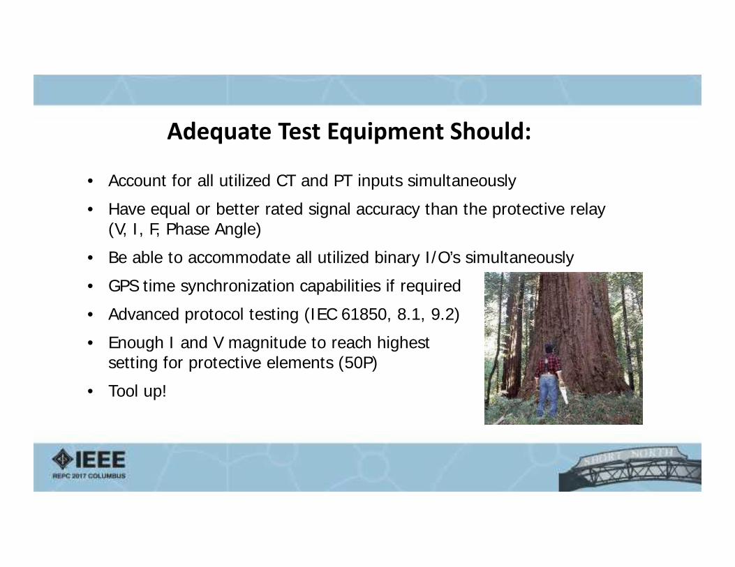
Adequate Test Equipment Should:
• Account for all utilized CT and PT inputs simultaneously
• Have equal or better rated signal accuracy than the protective relay(V, I, F, Phase Angle)
• Be able to accommodate all utilized binary I/O’s simultaneously
• GPS time synchronization capabilities if required
• Advanced protocol testing (IEC 61850, 8.1, 9.2)
• Enough I and V magnitude to reach highestsetting for protective elements (50P)
• Tool up!
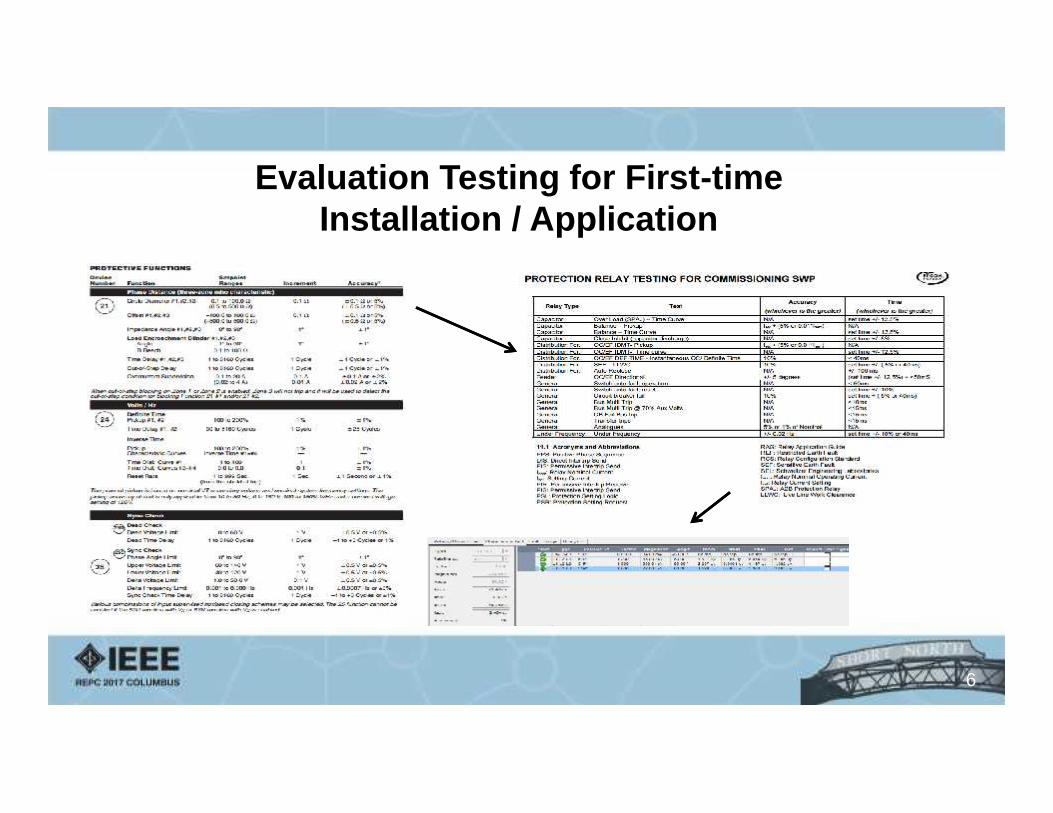
Evaluation Testing for First-timeInstallation / Application
6

Commission Testing
7
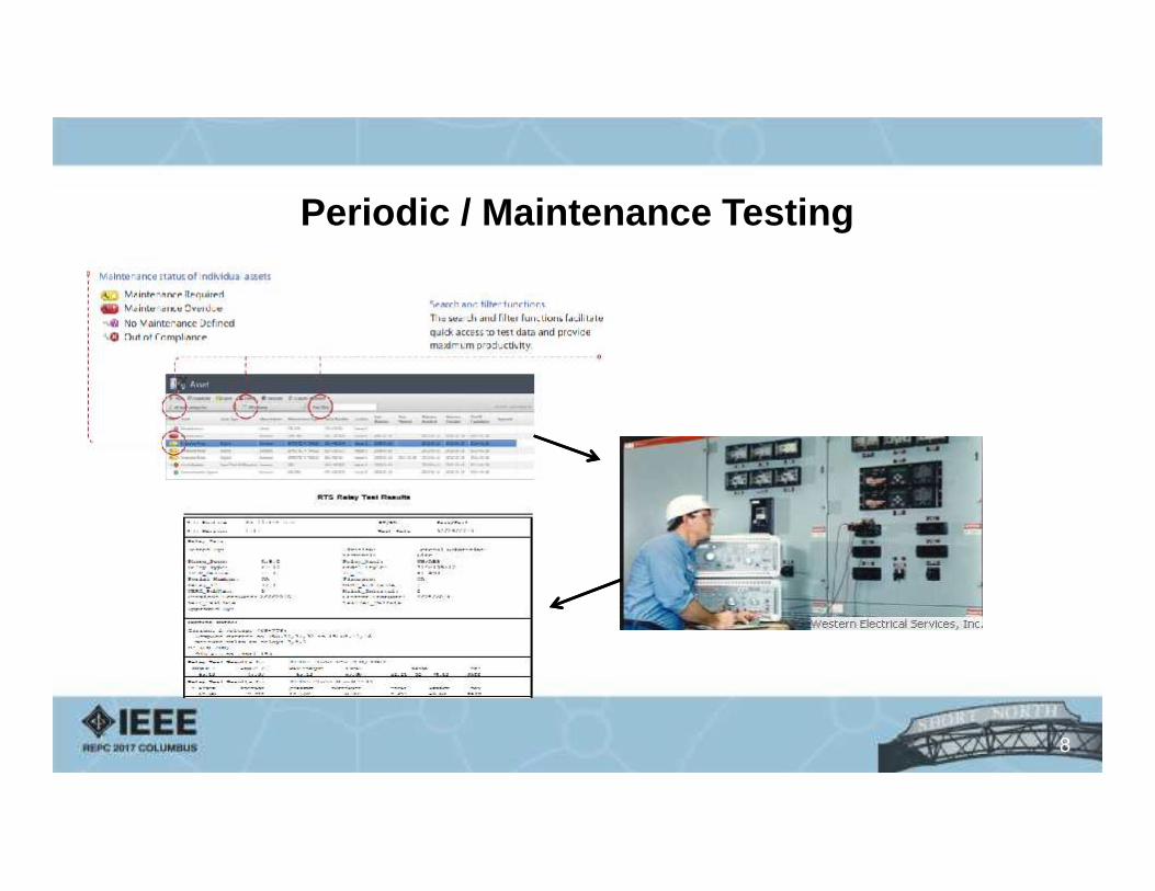
Periodic / Maintenance Testing
8
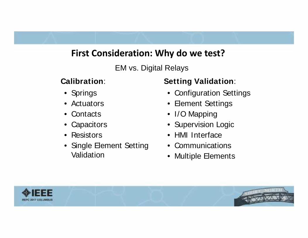
EM vs. Digital Relays
Calibration:• Springs• Actuators• Contacts• Capacitors• Resistors• Single Element Setting
Validation
Setting Validation:• Configuration Settings• Element Settings• I/O Mapping• Supervision Logic• HMI Interface• Communications• Multiple Elements
9
First Consideration: Why do we test?
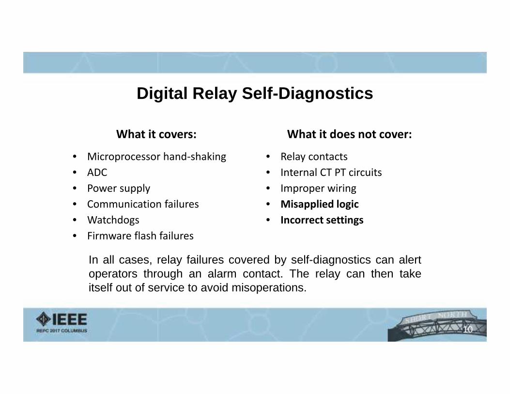
Digital Relay Self-Diagnostics
What it covers:
• Microprocessor hand-shaking• ADC• Power supply• Communication failures• Watchdogs• Firmware flash failures
What it does not cover:
• Relay contacts• Internal CT PT circuits• Improper wiring• Misapplied logic• Incorrect settings
In all cases, relay failures covered by self-diagnostics can alertoperators through an alarm contact. The relay can then takeitself out of service to avoid misoperations.
10
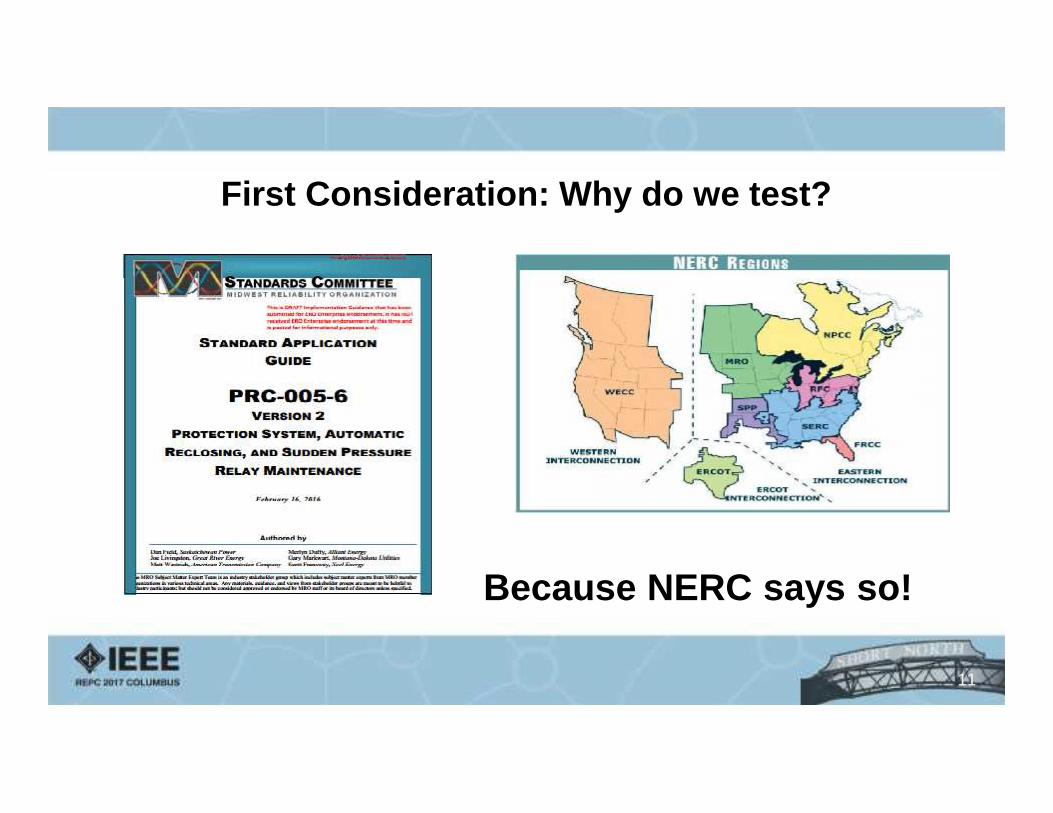
First Consideration: Why do we test?
Because NERC says so!
11
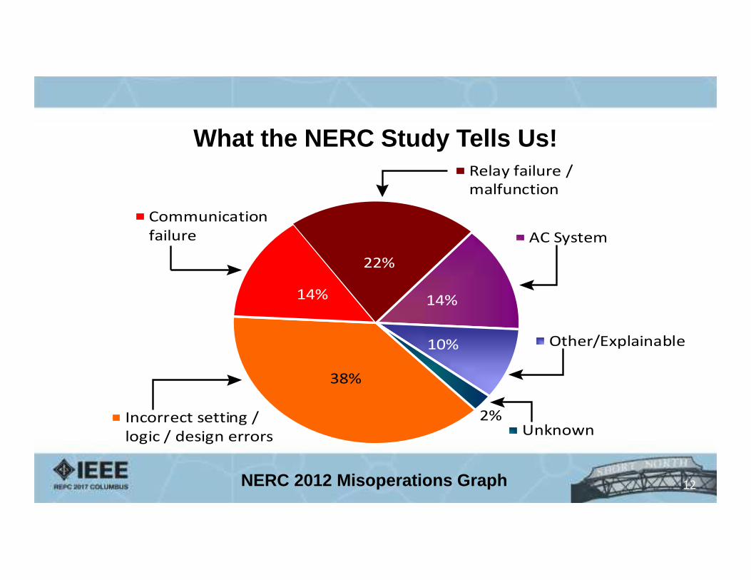
What the NERC Study Tells Us!
38%
14%
22%
14%
10%
2%Incorrect setting /logic / design errors
Communicationfailure
Relay failure /malfunction
AC System
Other/Explainable
Unknown
NERC 2012 Misoperations Graph 12
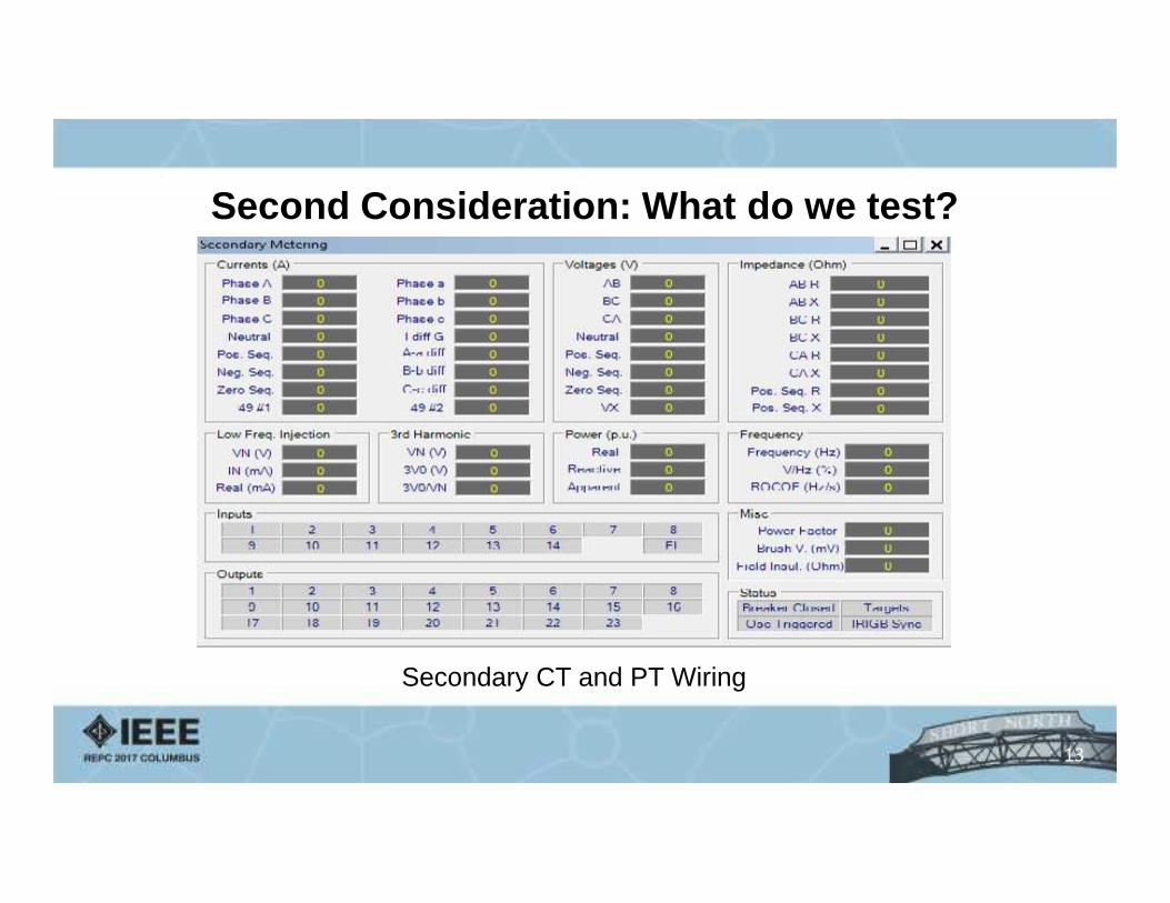
Second Consideration: What do we test?
Secondary CT and PT Wiring
13
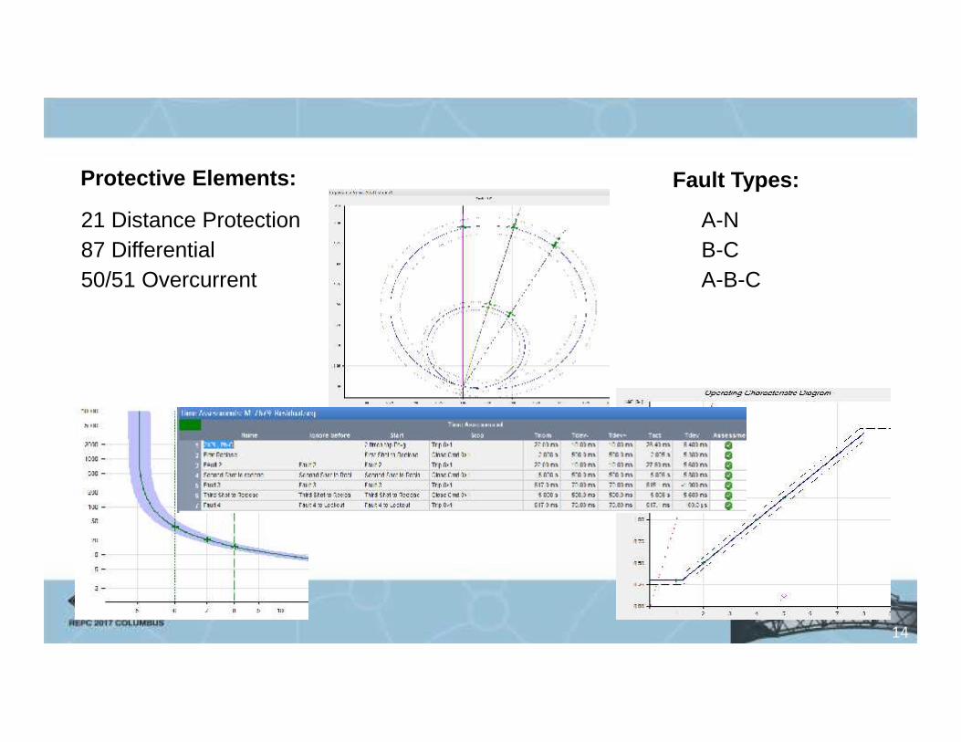
Protective Elements:
21 Distance Protection87 Differential50/51 Overcurrent
A-NB-CA-B-C
Fault Types:
14
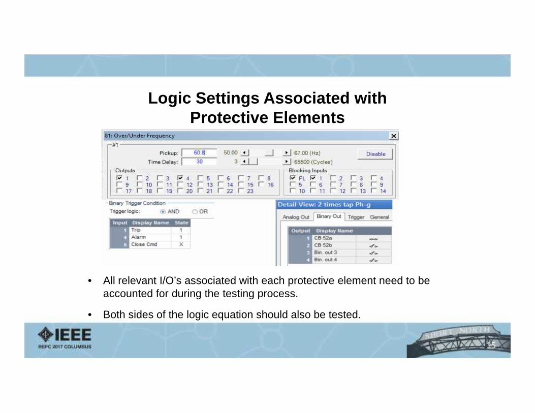
Logic Settings Associated withProtective Elements
• All relevant I/O’s associated with each protective element need to beaccounted for during the testing process.
• Both sides of the logic equation should also be tested.
15
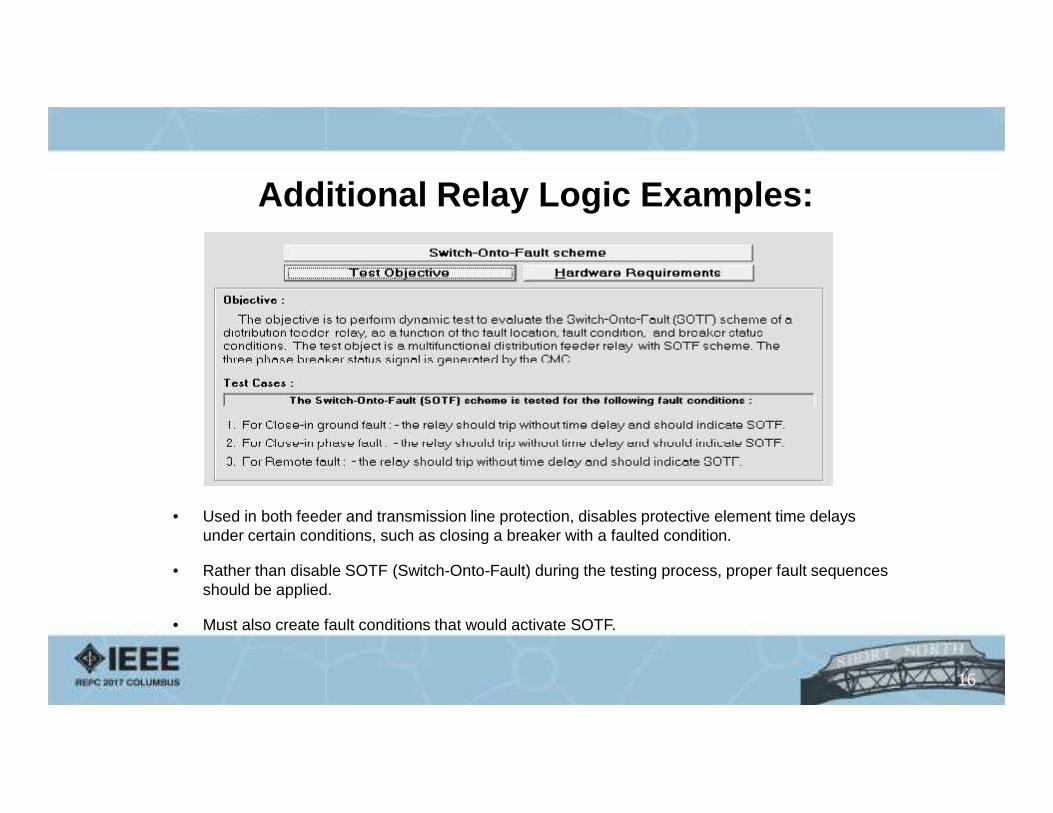
Additional Relay Logic Examples:
• Used in both feeder and transmission line protection, disables protective element time delaysunder certain conditions, such as closing a breaker with a faulted condition.
• Rather than disable SOTF (Switch-Onto-Fault) during the testing process, proper fault sequencesshould be applied.
• Must also create fault conditions that would activate SOTF.
16
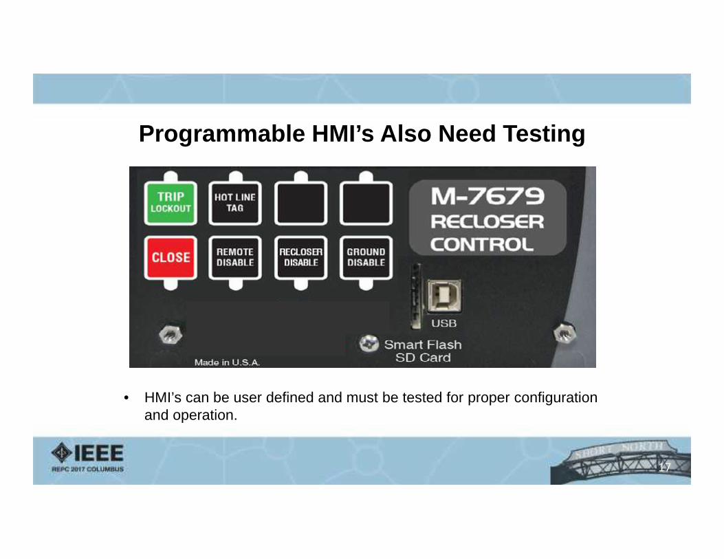
Programmable HMI’s Also Need Testing
• HMI’s can be user defined and must be tested for proper configurationand operation.
17
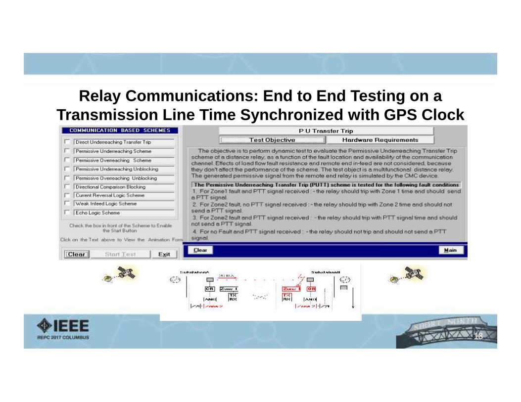
Relay Communications: End to End Testing on aTransmission Line Time Synchronized with GPS Clock
18
Third Consideration: How do we test?
“Thinking logically as to how a relayresponds in a faulted condition helpsto visualize a proper test sequence.”
- Drew Welton
19
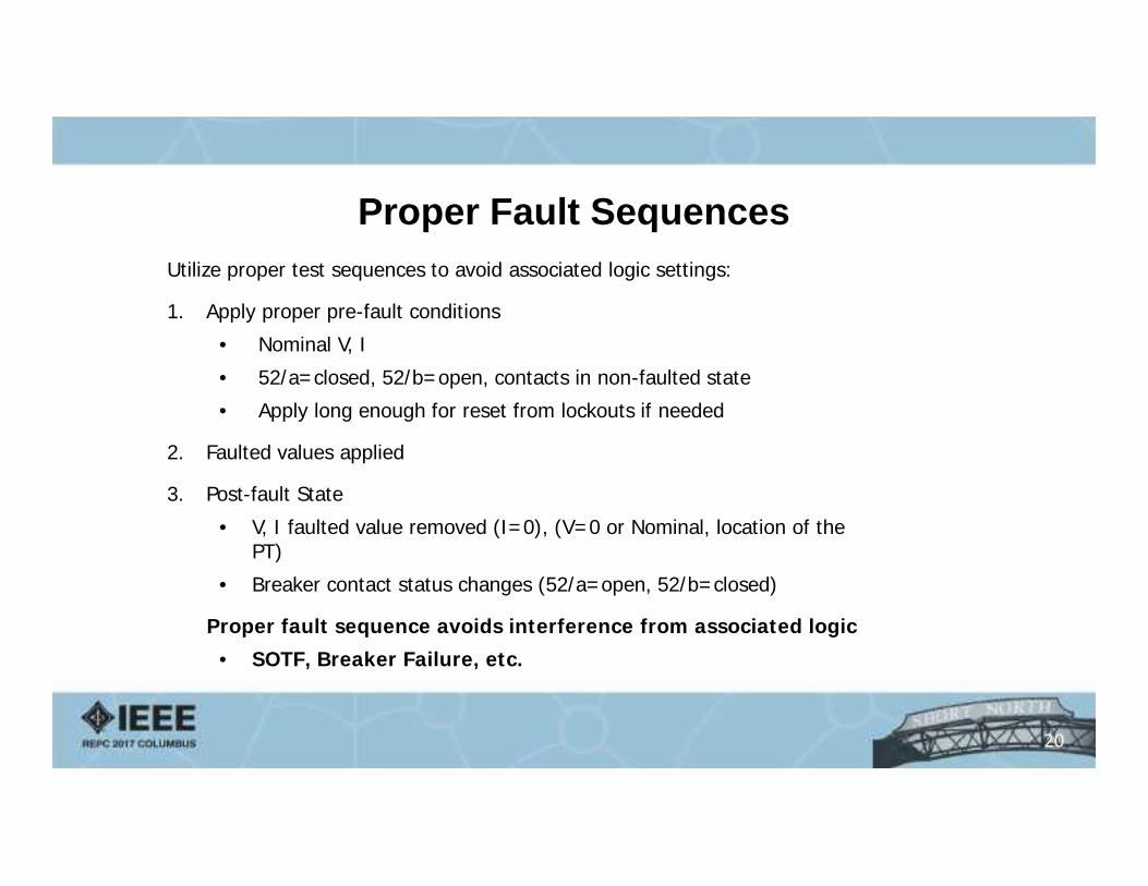
Utilize proper test sequences to avoid associated logic settings:
1. Apply proper pre-fault conditions
• Nominal V, I
• 52/a=closed, 52/b=open, contacts in non-faulted state
• Apply long enough for reset from lockouts if needed
2. Faulted values applied
3. Post-fault State
• V, I faulted value removed (I=0), (V=0 or Nominal, location of thePT)
• Breaker contact status changes (52/a=open, 52/b=closed)
Proper fault sequence avoids interference from associated logic
• SOTF, Breaker Failure, etc.
Proper Fault Sequences
20

Utilize system parameters to simulate true faulted conditions- Real Time Digital Simulations create true fault values and evaluates
relay performance- Ignores actual relay settings- Validates that settings have been calculated properly for the application- Can create multiple test scenarios (fault type, location, magnitude)
21
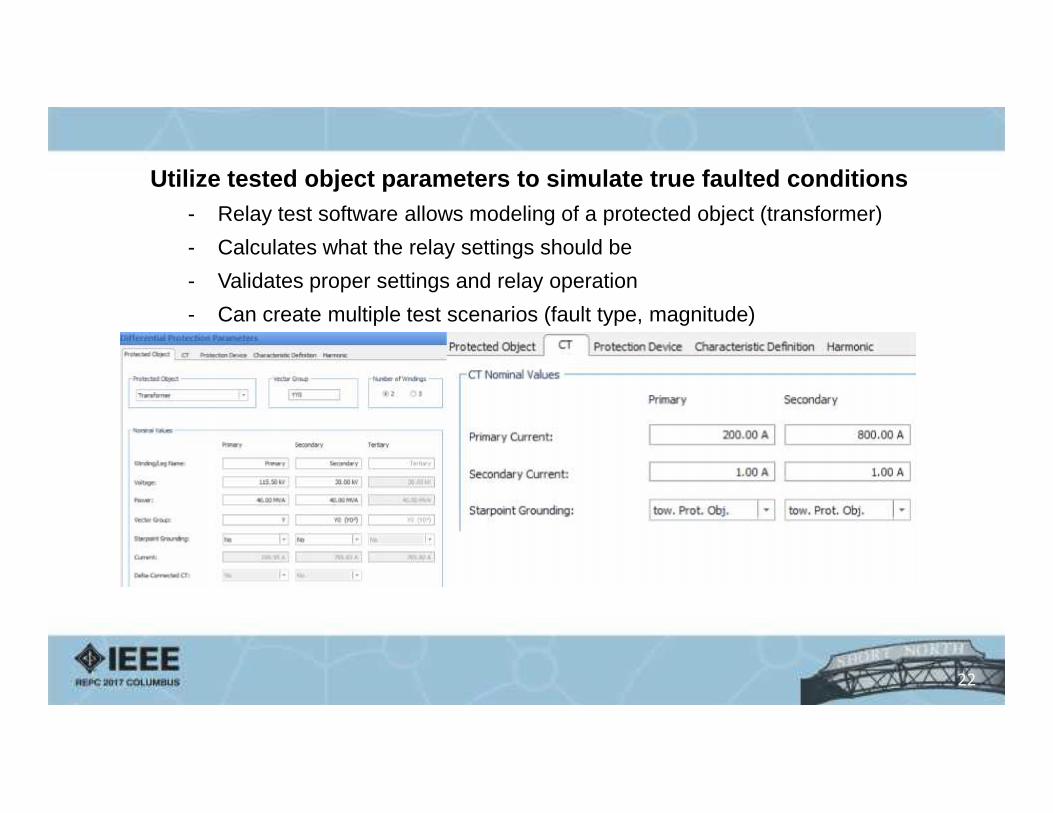
Utilize tested object parameters to simulate true faulted conditions- Relay test software allows modeling of a protected object (transformer)- Calculates what the relay settings should be- Validates proper settings and relay operation- Can create multiple test scenarios (fault type, magnitude)
22

Modeling parameters for a 2-winding power transformer
23
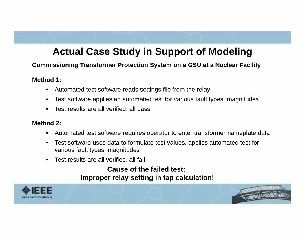
Actual Case Study in Support of ModelingCommissioning Transformer Protection System on a GSU at a Nuclear Facility
Method 1:• Automated test software reads settings file from the relay• Test software applies an automated test for various fault types, magnitudes• Test results are all verified, all pass.
Method 2:• Automated test software requires operator to enter transformer nameplate data• Test software uses data to formulate test values, applies automated test for
various fault types, magnitudes• Test results are all verified, all fail!
Cause of the failed test:Improper relay setting in tap calculation!
24
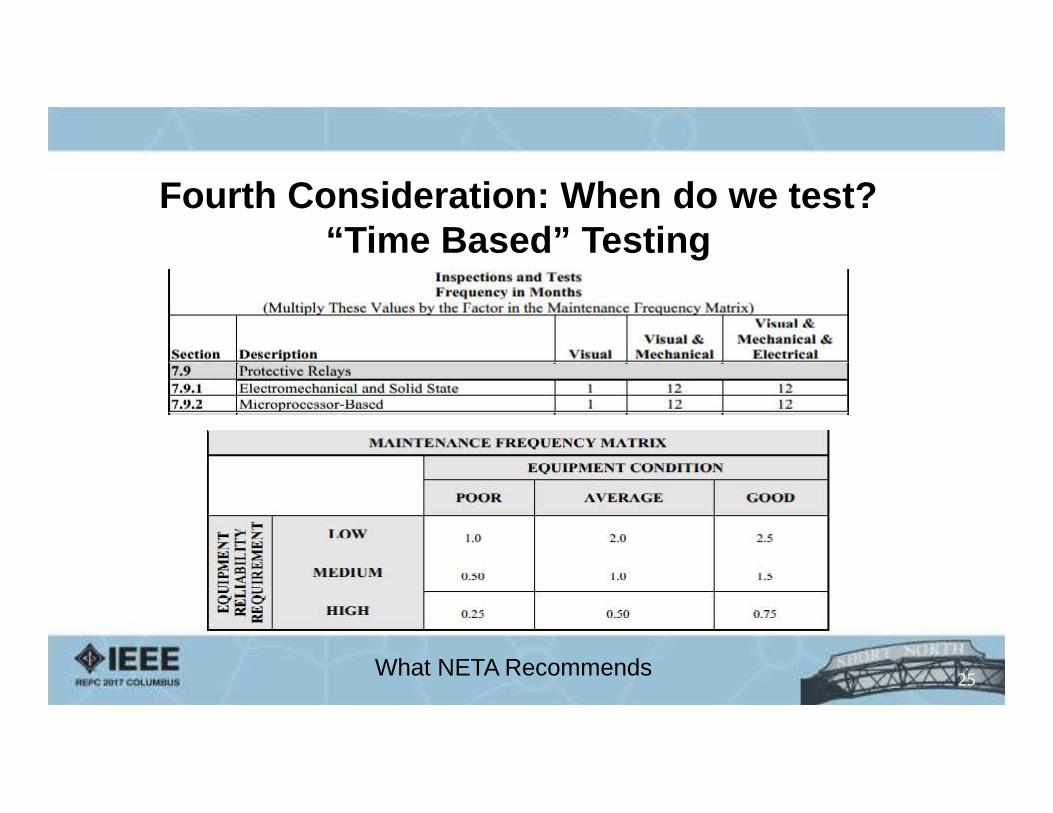
Fourth Consideration: When do we test?“Time Based” Testing
What NETA Recommends 25
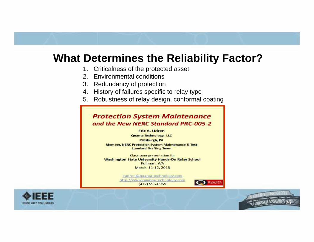
What Determines the Reliability Factor?1. Criticalness of the protected asset2. Environmental conditions3. Redundancy of protection4. History of failures specific to relay type5. Robustness of relay design, conformal coating
26
27
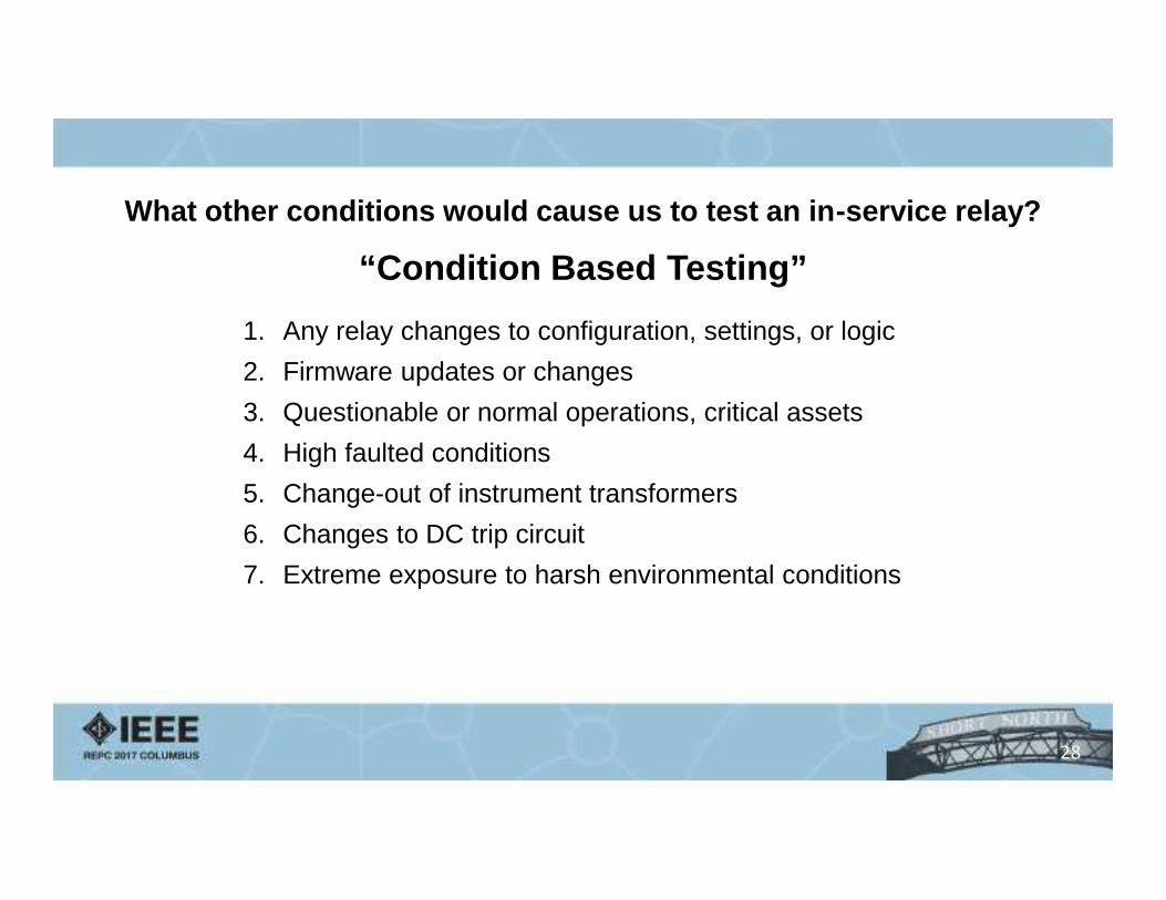
What other conditions would cause us to test an in-service relay?
“Condition Based Testing”1. Any relay changes to configuration, settings, or logic2. Firmware updates or changes3. Questionable or normal operations, critical assets4. High faulted conditions5. Change-out of instrument transformers6. Changes to DC trip circuit7. Extreme exposure to harsh environmental conditions
28
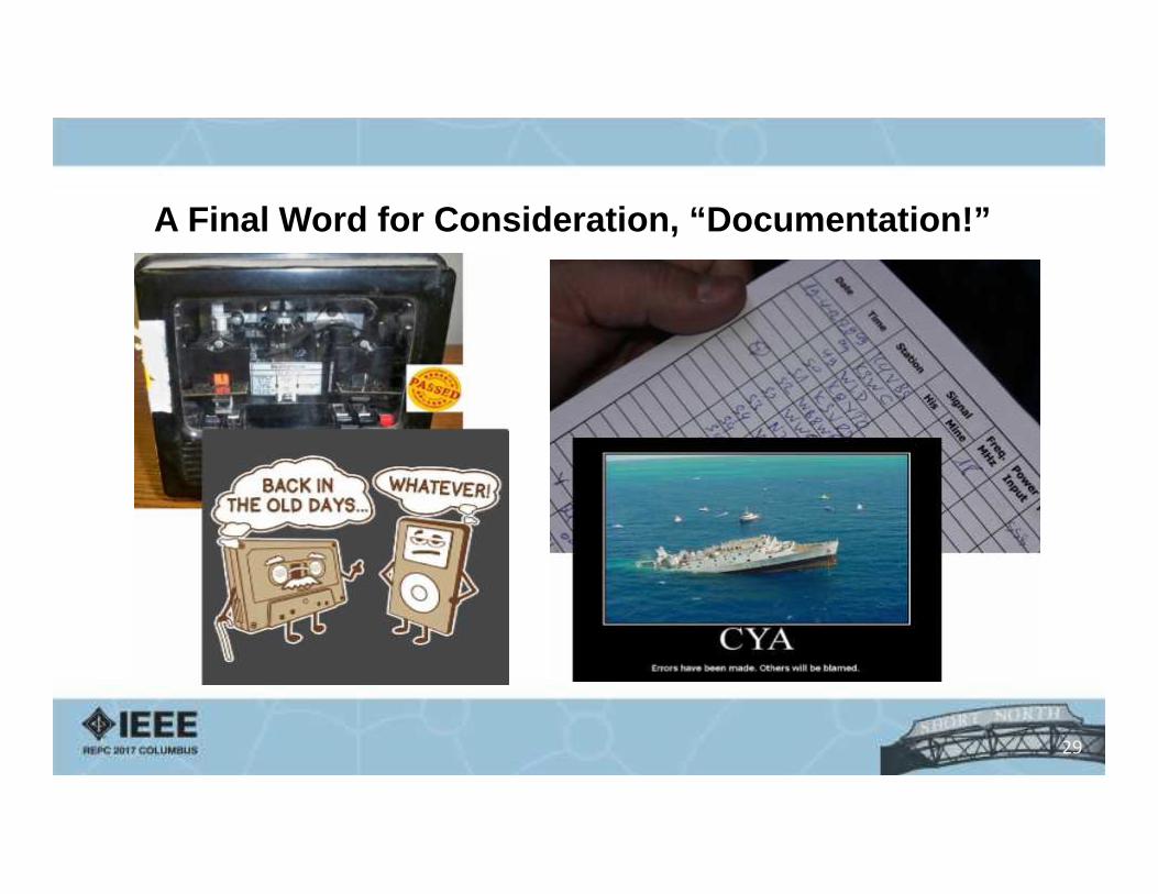
A Final Word for Consideration, “Documentation!”
29
A Final Word for Consideration, “Documentation!”• Modern test sets offer testing software• All testing software generates test report documents• All relay technicians should have a common system of documentation
handling• Relay test reports should be systematically archived after review• Test reports should be easily retrievable when needed
NERC may be here soon, audits are inevitable!
30
Questions?