Solar House r- Maintenance and Operation of Stand-Alone Photovoltaic Systems
IMPLEMENTATION OF A STAND-ALONE PHOTOVOLTAIC SYSTEM BASED ON DECENTRALIZED DC-DC CONVERTERS
Diogo B. Cândido, Jonatan R. R. Zientarski, Rafael C. Beltrame,
José R. Pinheiro, Leandro Michels and Hélio L. Hey
Federal University of Santa Maria – UFSM Power Electronics and Control Research Group – GEPOC
Santa Maria - RS - Brazil [email protected], [email protected]
Abstract – This paper proposes a stand-alone photovoltaic (PV) system that has as its input stage a set of DC-DC converters, which aim to perform the input energy processing with maximum power point tracking in a decentralized form. As battery charger the system possesses a bidirectional converter for controlling the power flux from/to battery bank, which is out of the main power path. The output stage is performed by an inverter. Previous studies have demonstrated that the decentralized input stage can provide an efficiency gain of 16% in situations where one or more photovoltaic panel is shaded, damaged or aged. The paper analyzes all operation modes of the proposed PV system, considering different levels of load energy demand and of solar irradiation. The proposed system is validated by simulation and experimental results.
1 Keywords – Decentralized Photovoltaic Systems, MPPT.
I. INTRODUCTION
The constantly increasing of global energy demand
together with worldwide concern about environmental impacts generated by energy production, mainly those that make use of fossil fuels, has heightened the interest in environmentally-friendly energy sources. One technology that has been receiving a great deal of attention is photovoltaic (PV) technology, mostly due to its advantages such as direct energy conversion without intermediate thermal processes or engines, easy building-integration in residential or commercial buildings, low environmental impact and modularity. Its environmentally-friendly qualities have contributed to the expansion of the installed capacity of PV systems around the world, which had reached more than 9.2 GW at the beginning of 2008 [1].
The increasing global interest in PV systems has led to competition among manufacturers, who have been aiming to obtain more efficient and cheaper PV panels, and to make PV technology more attractive and competitive when compared to other renewable technologies. Concomitantly, much research has been focused on static converters in an effort to obtain higher efficiency and better maximum power point tracking and, thus, maximize PV energy conversion. PV systems can be classified as Grid-Connected and Stand-Alone PV systems. Manuscript received 31/08/2009. Revised on 11/04/2010. Accepted for publication in 15/05/2010 by recommendation of the Editor Fernando L. M. Antunes.
Grid-connected systems are designed to operate in parallel and interconnected with the electric utility grid. This allows the power produced by the PV system to either supply on-site electrical loads or to back-feed the grid when the PV system output is greater than the on-site load demand. Stand-alone PV systems are designed to operate independently of the electric utility grid. Most stand-alone PV systems present an additional energy storage system to supply the load when there is no sunlight. This is an attractive alternative to feed isolated loads without access to distribution power lines or where its extension is not economically viable [1].
Typical stand-alone PV systems use a battery bank as an energy storage system. The battery bank represents the most onerous part in a stand-alone PV system when considering its maintenance cost [2]-[4]. In cyclic applications, where the battery is daily charged and discharged, the battery is the most expensive element of the system throughout its useful life. Although it costs up to 15% of the initial installation cost, it represents up to 46% of the cost when maintenance costs are considered [5]. This high cost is due to the battery’s short lifetime compared to the other system components. It is important to highlight that relative cost of the battery bank will be even more significant if a suitable battery charge process is not used. Therefore, it is imperative to choose a charge/discharge method that maximizes battery lifetime. In this paper some battery charging methods are discussed and the most suitable for the proposed stand-alone PV system is indicated.
In relation to PV stand-alone system configurations, the centralized topology is the most used. Due to the employment of a single converter to perform the maximum power point tracking (MPPT), the generation capability of the PV array is not fully utilized in situations in which the panels are shaded, damaged and/or aged, contributing to decreased efficiency and increased cost of the energy generated by such systems. As an alternative to this configuration, this paper presents a stand-alone PV system which uses a decentralized energy configuration in the input stage. Additionally, based on the operation modes of the systems, the energy management strategy to be used is discussed and presented. The proposed configuration provides a better utilization of the energy generated by the PV array by means of individualized MPPT, as well as a better management of the energy stored in the battery bank, aiming at an increased life cycle and reduction of maintenance costs.
220 Eletrônica de Potência, Campinas, v. 15, n. 3, p.220-228, jun./ago. 2010
II. PHOTOVOLTAIC SYSTEMS A. Centralized Photovoltaic Systems
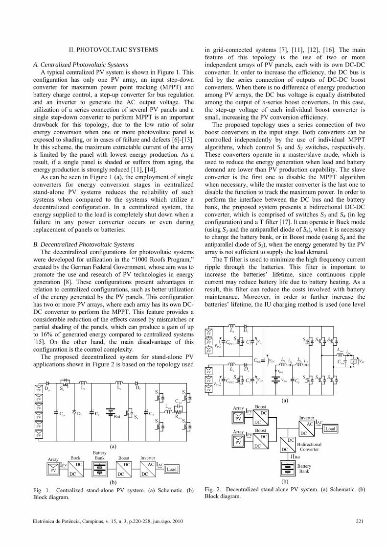
A typical centralized PV system is shown in Figure 1. This configuration has only one PV array, an input step-down converter for maximum power point tracking (MPPT) and battery charge control, a step-up converter for bus regulation and an inverter to generate the AC output voltage. The utilization of a series connection of several PV panels and a single step-down converter to perform MPPT is an important drawback for this topology, due to the low ratio of solar energy conversion when one or more photovoltaic panel is exposed to shading, or in cases of failure and defects [6]-[13]. In this scheme, the maximum extractable current of the array is limited by the panel with lowest energy production. As a result, if a single panel is shaded or suffers from aging, the energy production is strongly reduced [11], [14].
As can be seen in Figure 1 (a), the employment of single converters for energy conversion stages in centralized stand-alone PV systems reduces the reliability of such systems when compared to the systems which utilize a decentralized configuration. In a centralized system, the energy supplied to the load is completely shut down when a failure in any power converter occurs or even during replacement of panels or batteries. B. Decentralized Photovoltaic Systems
The decentralized configurations for photovoltaic systems were developed for utilization in the “1000 Roofs Program,” created by the German Federal Government, whose aim was to promote the use and research of PV technologies in energy generation [8]. These configurations present advantages in relation to centralized configurations, such as better utilization of the energy generated by the PV panels. This configuration has two or more PV arrays, where each array has its own DC-DC converter to perform the MPPT. This feature provides a considerable reduction of the effects caused by mismatches or partial shading of the panels, which can produce a gain of up to 16% of generated energy compared to centralized systems [15]. On the other hand, the main disadvantage of this configuration is the control complexity.
The proposed decentralized system for stand-alone PV applications shown in Figure 2 is based on the topology used
in grid-connected systems [7], [11], [12], [16]. The main feature of this topology is the use of two or more independent arrays of PV panels, each with its own DC-DC converter. In order to increase the efficiency, the DC bus is fed by the series connection of outputs of DC-DC boost converters. When there is no difference of energy production among PV arrays, the DC bus voltage is equally distributed among the output of n-series boost converters. In this case, the step-up voltage of each individual boost converter is small, increasing the PV conversion efficiency.
The proposed topology uses a series connection of two boost converters in the input stage. Both converters can be controlled independently by the use of individual MPPT algorithms, which control S1 and S2 switches, respectively. These converters operate in a master/slave mode, which is used to reduce the energy generation when load and battery demand are lower than PV production capability. The slave converter is the first one to disable the MPPT algorithm when necessary, while the master converter is the last one to disable the function to track the maximum power. In order to perform the interface between the DC bus and the battery bank, the proposed system presents a bidirectional DC-DC converter, which is comprised of switches S3 and S4 (in leg configuration) and a T filter [17]. It can operate in Buck mode (using S3 and the antiparallel diode of S4), when it is necessary to charge the battery bank, or in Boost mode (using S4 and the antiparallel diode of S3), when the energy generated by the PV array is not sufficient to supply the load demand.
The T filter is used to minimize the high frequency current ripple through the batteries. This filter is important to increase the batteries’ lifetime, since continuous ripple current may reduce battery life due to battery heating. As a result, this filter can reduce the costs involved with battery maintenance. Moreover, in order to further increase the batteries’ lifetime, the IU charging method is used (one level
S1
S2
S3
S4
Lout
Cout
Rout
L1 L2
D1
D2
Cpv
Dpv
C1 C2C1 C2Bat
PV
PV
PV
PV
PV
PV
Sa
Sb
(a)
PV
Array Buck Boost
DC DCDC DC
DC DCDC DC
DCDC
ACAC
BatteryBank Inverter
LoadIACIPV
(b)
Fig. 1. Centralized stand-alone PV system. (a) Schematic. (b) Block diagram.
PV
PV
PV
PV
PV
PVS2
S1
S6 S8
S7S5
Lout
Lf Lb
L1
L2
Cout
CPV2 C2
CPV1 C1
CDC
Cf
D2
D1
z
vPVs
vPVm
vBat
vACvDC
vC1
vC2
iLb
iAC
iLf
iBat
S4
S3
(a)
PV
Array Boost
BidirectionalConverter
DC
DC
DC
DCDC
AC
BatteryBank
Inverter
LoadIAC
IPV
IBat
PV
Boost
DC
DCIPV
(b)
Fig. 2. Decentralized stand-alone PV system. (a) Schematic. (b) Block diagram.
Eletrônica de Potência, Campinas, v. 15, n. 3, p.220-228, jun./ago. 2010 221
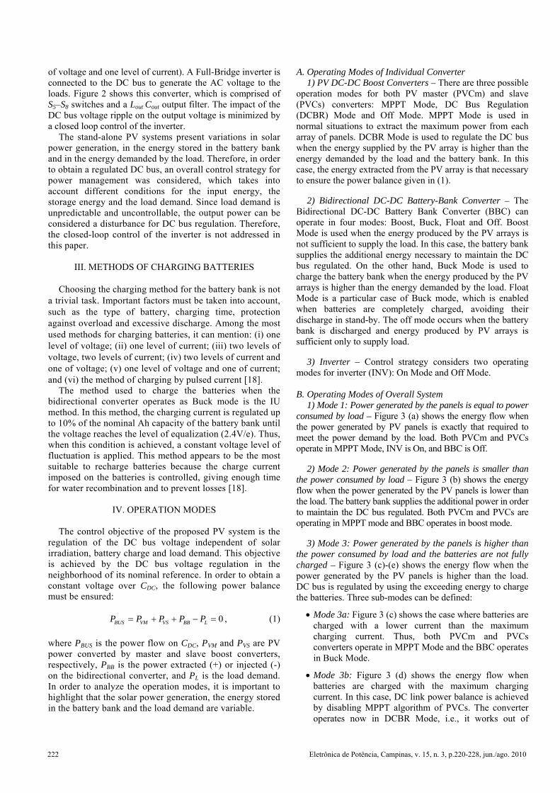
of voltage and one level of current). A Full-Bridge inverter is connected to the DC bus to generate the AC voltage to the loads. Figure 2 shows this converter, which is comprised of S5–S8 switches and a Lout Cout output filter. The impact of the DC bus voltage ripple on the output voltage is minimized by a closed loop control of the inverter.
The stand-alone PV systems present variations in solar power generation, in the energy stored in the battery bank and in the energy demanded by the load. Therefore, in order to obtain a regulated DC bus, an overall control strategy for power management was considered, which takes into account different conditions for the input energy, the storage energy and the load demand. Since load demand is unpredictable and uncontrollable, the output power can be considered a disturbance for DC bus regulation. Therefore, the closed-loop control of the inverter is not addressed in this paper.
III. METHODS OF CHARGING BATTERIES
Choosing the charging method for the battery bank is not
a trivial task. Important factors must be taken into account, such as the type of battery, charging time, protection against overload and excessive discharge. Among the most used methods for charging batteries, it can mention: (i) one level of voltage; (ii) one level of current; (iii) two levels of voltage, two levels of current; (iv) two levels of current and one of voltage; (v) one level of voltage and one of current; and (vi) the method of charging by pulsed current [18].
The method used to charge the batteries when the bidirectional converter operates as Buck mode is the IU method. In this method, the charging current is regulated up to 10% of the nominal Ah capacity of the battery bank until the voltage reaches the level of equalization (2.4V/e). Thus, when this condition is achieved, a constant voltage level of fluctuation is applied. This method appears to be the most suitable to recharge batteries because the charge current imposed on the batteries is controlled, giving enough time for water recombination and to prevent losses [18].
IV. OPERATION MODES
The control objective of the proposed PV system is the regulation of the DC bus voltage independent of solar irradiation, battery charge and load demand. This objective is achieved by the DC bus voltage regulation in the neighborhood of its nominal reference. In order to obtain a constant voltage over CDC, the following power balance must be ensured:
0BUS VM VS BB LP P P P P= + + − = , (1)
where PBUS is the power flow on CDC, PVM and PVS are PV power converted by master and slave boost converters, respectively, PBB is the power extracted (+) or injected (-) on the bidirectional converter, and PL is the load demand. In order to analyze the operation modes, it is important to highlight that the solar power generation, the energy stored in the battery bank and the load demand are variable.
A. Operating Modes of Individual Converter 1) PV DC-DC Boost Converters – There are three possible
operation modes for both PV master (PVCm) and slave (PVCs) converters: MPPT Mode, DC Bus Regulation (DCBR) Mode and Off Mode. MPPT Mode is used in normal situations to extract the maximum power from each array of panels. DCBR Mode is used to regulate the DC bus when the energy supplied by the PV array is higher than the energy demanded by the load and the battery bank. In this case, the energy extracted from the PV array is that necessary to ensure the power balance given in (1).
2) Bidirectional DC-DC Battery-Bank Converter – The Bidirectional DC-DC Battery Bank Converter (BBC) can operate in four modes: Boost, Buck, Float and Off. Boost Mode is used when the energy produced by the PV arrays is not sufficient to supply the load. In this case, the battery bank supplies the additional energy necessary to maintain the DC bus regulated. On the other hand, Buck Mode is used to charge the battery bank when the energy produced by the PV arrays is higher than the energy demanded by the load. Float Mode is a particular case of Buck mode, which is enabled when batteries are completely charged, avoiding their discharge in stand-by. The off mode occurs when the battery bank is discharged and energy produced by PV arrays is sufficient only to supply load.
3) Inverter – Control strategy considers two operating modes for inverter (INV): On Mode and Off Mode.
B. Operating Modes of Overall System
1) Mode 1: Power generated by the panels is equal to power consumed by load – Figure 3 (a) shows the energy flow when the power generated by PV panels is exactly that required to meet the power demand by the load. Both PVCm and PVCs operate in MPPT Mode, INV is On, and BBC is Off.
2) Mode 2: Power generated by the panels is smaller than the power consumed by load – Figure 3 (b) shows the energy flow when the power generated by the PV panels is lower than the load. The battery bank supplies the additional power in order to maintain the DC bus regulated. Both PVCm and PVCs are operating in MPPT mode and BBC operates in boost mode.
3) Mode 3: Power generated by the panels is higher than the power consumed by load and the batteries are not fully charged – Figure 3 (c)-(e) shows the energy flow when the power generated by the PV panels is higher than the load. DC bus is regulated by using the exceeding energy to charge the batteries. Three sub-modes can be defined:
• Mode 3a: Figure 3 (c) shows the case where batteries are charged with a lower current than the maximum charging current. Thus, both PVCm and PVCs converters operate in MPPT Mode and the BBC operates in Buck Mode.
• Mode 3b: Figure 3 (d) shows the energy flow when batteries are charged with the maximum charging current. In this case, DC link power balance is achieved by disabling MPPT algorithm of PVCs. The converter operates now in DCBR Mode, i.e., it works out of
222 Eletrônica de Potência, Campinas, v. 15, n. 3, p.220-228, jun./ago. 2010
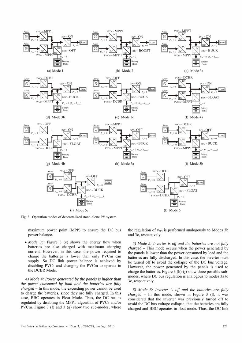
maximum power point (MPP) to ensure the DC bus power balance.
• Mode 3c: Figure 3 (e) shows the energy flow when batteries are also charged with maximum charging current. However, in this case, the power required to charge the batteries is lower than only PVCm can supply. So DC link power balance is achieved by disabling PVCs and changing the PVCm to operate in the DCBR Mode.
4) Mode 4: Power generated by the panels is higher than the power consumed by load and the batteries are fully charged – In this mode, the exceeding power cannot be used to charge the batteries, since they are fully charged. In this case, BBC operates in Float Mode. Thus, the DC bus is regulated by disabling the MPPT algorithm of PVCs and/or PVCm. Figure 3 (f) and 3 (g) show two sub-modes, where
the regulation of vDC is performed analogously to Modes 3b and 3c, respectively.
5) Mode 5: Inverter is off and the batteries are not fully charged – This mode occurs when the power generated by the panels is lower than the power consumed by load and the batteries are fully discharged. In this case, the inverter must be turned off to avoid the collapse of the DC bus voltage. However, the power generated by the panels is used to charge the batteries. Figure 3 (h)-(j) show three possible sub-modes, where DC bus regulation is analogous to modes 3a to 3c, respectively.
6) Mode 6: Inverter is off and the batteries are fully charged – In this mode, shown in Figure 3 (l), it was considered that the inverter was previously turned off to avoid the DC bus voltage collapse, that the batteries are fully charged and BBC operates in float mode. Thus, the DC link
PVCm = MPPTBBC = OFF
BatteryBank
PVDC
DC
DC
PVCs = MPPT
PV
Array
LoadDC
DC
DC
AC
DC
PVS > 0
PBB = 0
PVM > 0
PL > 0
INV = ON
BatteryBank
PVDC
DC
DC
PV
Array
LoadDC
DC
DC
AC
DC
PVS > 0
PBB > 0
PVM > 0
PL > 0
PVCm = MPPTBBC = BOOST
PVCs = MPPTINV = ON
BatteryBank
PVDC
DC
DC
PV
Array
LoadDC
DC
DC
AC
DC
PVS > 0
PVM > 0
PL > 0
PVCm = MPPTBBC = BUCK
PVCs = MPPTINV = ON
PBB < 0 (I IBat Batmax < )
(a) Mode 1 (b) Mode 2 (c) Mode 3a
BatteryBank
LoadDC
AC
PL > 0
BBC = BUCK
INV = ON
PVDC
DC
DC
PV
Array
DC
DC
DC
PVS > 0
PVM > 0PVCm = MPPT
PVCs = DCBR
PBB < 0 (I IBat Batmax = )
BatteryBank
LoadDC
AC
PL > 0
BBC = BUCK
INV = ON
PVDC
DC
DC
PV
Array
DC
DC
DC
PVS > 0
PVM > 0PVCm = DCBR
PVCs = OFF
PBB < 0 (I IBat Batmax = )
BBC = FLOAT
BatteryBank
LoadDC
AC
PBB = 0
PL > 0
INV = ON
PVCm = MPPT
PVDC
DC
DC
PVCs = DCBR
PV
Array
DC
DC
DC
PVS > 0
PVM > 0
(d) Mode 3b (e) Mode 3c (f) Mode 4a
BBC = FLOAT
BatteryBank
LoadDC
AC
PBB = 0
PL > 0
INV = ON
PVCm = DCBR
PVDC
DC
DC
PVCs = OFF
PV
Array
DC
DC
DC
PVS > 0
PVM > 0
BatteryBank
PVDC
DC
DC
PV
Array
LoadDC
DC
DC
AC
DC
PVS > 0
PVM > 0
PL = 0
PVCm = MPPTBBC = BUCK
PVCs = MPPTINV = OFF
PBB < 0 (I IBat Batmax < )
BatteryBank
PVDC
DC
DC
PV
Array
LoadDC
DC
DC
AC
DC
PVS > 0
PVM > 0
PL = 0
PVCm = MPPTBBC = BUCK
PVCs = DCBRINV = OFF
PBB < 0 (I IBat Batmax = )
(g) Mode 4b (h) Mode 5a (i) Mode 5b
BatteryBank
PVDC
DC
DC
PV
Array
LoadDC
DC
DC
AC
DC
PVS > 0
PVM > 0
PL = 0
PVCm = DCBRBBC = BUCK
PVCs = OFFINV = OFF
PBB < 0 (I IBat Batmax = )
BatteryBank
PVDC
DC
DC
PV
Array
LoadDC
DC
DC
AC
DC
PVS > 0
PVM > 0
PL = 0
PVCm = DCBRBBC = FLOAT
PVCs = OFFINV = OFF
PBB = 0
(j) Mode 5c (l) Mode 6
Fig. 3. Operation modes of decentralized stand-alone PV system.
Eletrônica de Potência, Campinas, v. 15, n. 3, p.220-228, jun./ago. 2010 223
power balance is achieved by disabling PVCs and changing the PVCm from MPPT to DCBR mode. It is worth mentioning that it was assumed that the inverter could not be turned on automatically due to safety requirements.
V. MPPT ALGORITHM
One of the obstacles to the dissemination of PV
technology is its high installation cost. Thus, it is essential to drain the maximum available power from PV panels to increase the global efficiency of the system and to reduce generated energy costs.
An important characteristic of PV panels is the existence of only one point of operation from which the maximum power can be extracted. The MPP (Maximum Power Point) for a given level of solar radiation and temperature correspond to a single value of voltage (VMPP) and current (IMPP). Therefore, the objective of all MPPT techniques is to find this point independently of environmental conditions. The following features should be observed in the choice of the MPPT technique: time taken to reach the MPP, steady-state oscillation, and sensitivity to parametric variations.
In the proposed system, a modified P&O (Perturb & Observe) algorithm was used for MPPT. This algorithm changes the MPP by means of duty ratio modification in each Boost converter. Table I summarizes the operation of this algorithm [19].
Although the conventional and modified P&O algorithms present identical control logic to define the signal of the next perturbation, the conventional P&O algorithm uses a constant perturbation whereas the modified P&O algorithm uses a variable perturbation whose module is proportional to variations of power. This slight modification in the conventional algorithm results in a short tracking time and minimization of oscillations around the MPP.
VI. SIMULATION RESULTS
This section presents the simulation results for the
proposed PV system. The system was subjected to variations on load and/or solar radiation in order to analyze its behavior under the different operation modes analyzed. The specifications of the PV system are summarized in Table II.
As detailed in Section IV, this system has several operation modes and most of them have similar characteristics. In order to not include repetitive information, this section presents simulation results for each operating mode of the input boost converters (MPPT and DCBR functions) and for each operating mode of the bidirectional converter (buck and boost modes).
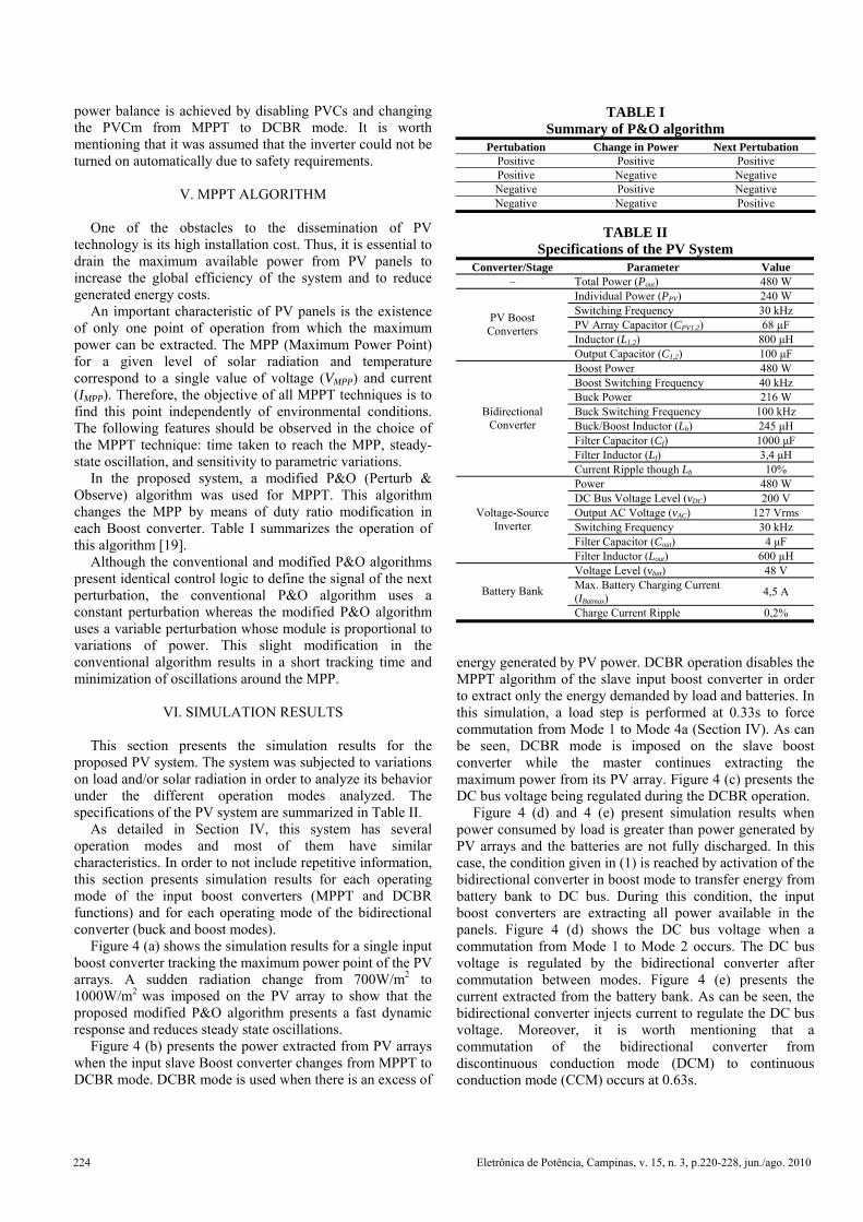
Figure 4 (a) shows the simulation results for a single input boost converter tracking the maximum power point of the PV arrays. A sudden radiation change from 700W/m2 to 1000W/m2
was imposed on the PV array to show that the proposed modified P&O algorithm presents a fast dynamic response and reduces steady state oscillations.
Figure 4 (b) presents the power extracted from PV arrays when the input slave Boost converter changes from MPPT to DCBR mode. DCBR mode is used when there is an excess of
energy generated by PV power. DCBR operation disables the MPPT algorithm of the slave input boost converter in order to extract only the energy demanded by load and batteries. In this simulation, a load step is performed at 0.33s to force commutation from Mode 1 to Mode 4a (Section IV). As can be seen, DCBR mode is imposed on the slave boost converter while the master continues extracting the maximum power from its PV array. Figure 4 (c) presents the DC bus voltage being regulated during the DCBR operation.
Figure 4 (d) and 4 (e) present simulation results when power consumed by load is greater than power generated by PV arrays and the batteries are not fully discharged. In this case, the condition given in (1) is reached by activation of the bidirectional converter in boost mode to transfer energy from battery bank to DC bus. During this condition, the input boost converters are extracting all power available in the panels. Figure 4 (d) shows the DC bus voltage when a commutation from Mode 1 to Mode 2 occurs. The DC bus voltage is regulated by the bidirectional converter after commutation between modes. Figure 4 (e) presents the current extracted from the battery bank. As can be seen, the bidirectional converter injects current to regulate the DC bus voltage. Moreover, it is worth mentioning that a commutation of the bidirectional converter from discontinuous conduction mode (DCM) to continuous conduction mode (CCM) occurs at 0.63s.
TABLE I Summary of P&O algorithm
Pertubation Change in Power Next Pertubation Positive Positive Positive Positive Negative Negative Negative Positive Negative Negative Negative Positive
TABLE II Specifications of the PV System
Converter/Stage Parameter Value – Total Power (Pout) 480 W
Individual Power (PPV) 240 W Switching Frequency 30 kHz PV Array Capacitor (CPV1,2) 68 µF Inductor (L1,2) 800 μH
PV Boost Converters
Output Capacitor (C1,2) 100 μF Boost Power 480 W Boost Switching Frequency 40 kHz Buck Power 216 W Buck Switching Frequency 100 kHz Buck/Boost Inductor (Lb) 245 μH Filter Capacitor (Cf) 1000 μF Filter Inductor (Lf) 3,4 μH
Bidirectional Converter
Current Ripple though Lb 10% Power 480 W DC Bus Voltage Level (vDC) 200 V Output AC Voltage (vAC) 127 Vrms Switching Frequency 30 kHz Filter Capacitor (Cout) 4 μF
Voltage-Source Inverter
Filter Inductor (Lout) 600 µH Voltage Level (vbat) 48 V Max. Battery Charging Current (IBatmax)
4,5 A Battery Bank
Charge Current Ripple 0,2%
224 Eletrônica de Potência, Campinas, v. 15, n. 3, p.220-228, jun./ago. 2010
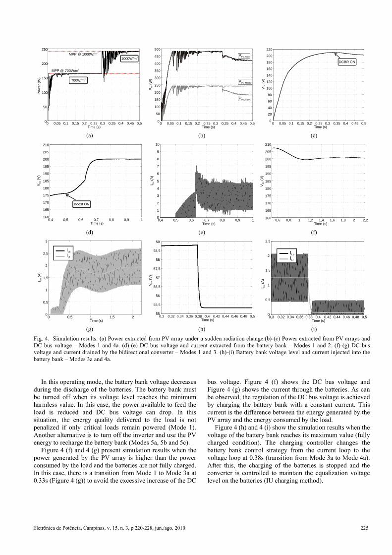
In this operating mode, the battery bank voltage decreases during the discharge of the batteries. The battery bank must be turned off when its voltage level reaches the minimum harmless value. In this case, the power available to feed the load is reduced and DC bus voltage can drop. In this situation, the energy quality delivered to the load is not penalized if only critical loads remain powered (Mode 1). Another alternative is to turn off the inverter and use the PV energy to recharge the battery bank (Modes 5a, 5b and 5c).
Figure 4 (f) and 4 (g) present simulation results when the power generated by the PV array is higher than the power consumed by the load and the batteries are not fully charged. In this case, there is a transition from Mode 1 to Mode 3a at 0.33s (Figure 4 (g)) to avoid the excessive increase of the DC
bus voltage. Figure 4 (f) shows the DC bus voltage and Figure 4 (g) shows the current through the batteries. As can be observed, the regulation of the DC bus voltage is achieved by charging the battery bank with a constant current. This current is the difference between the energy generated by the PV array and the energy consumed by the load.
Figure 4 (h) and 4 (i) show the simulation results when the voltage of the battery bank reaches its maximum value (fully charged condition). The charging controller changes the battery bank control strategy from the current loop to the voltage loop at 0.38s (transition from Mode 3a to Mode 4a). After this, the charging of the batteries is stopped and the converter is controlled to maintain the equalization voltage level on the batteries (IU charging method).
0 0,05 0,1 0,15 0,2 0,25 0,3 0,35 0,4 0,45 0,50
50
100
150
200
250
Time (s)
Pow
er (W
)
700W/m2
1000W/m2
MPP @ 700W/m2
MPP @ 1000W/m2
0 0,05 0,1 0,15 0,2 0,25 0,3 0,35 0,4 0,45 0,50
50
100
150
200
250
300
350
400
450
500
Time (s)
P (W
)P
V
PPV_Total
PPV_Master
PPV_Slave
0 0,05 0,1 0,15 0,2 0,25 0,3 0,35 0,4 0,45 0,50
20
40
60
80
100
120
140
160
180
200
220
Time (s)
V (V
)C
C
DCBR ON
(a) (b) (c)
0,4 0,5 0,6 0,7 0,8 0,9 1160
165
170
175
180
185
190
195
200
205
210
Time (s)
V (V
)D
C
Boost ON
0,4 0,5 0,6 0,7 0,8 0,9 10
1
2
3
4
5
6
7
8
9
10
Time (s)
I (A
)Ba
t
0,6 0,8 1 1,2 1,4 1,6 1,8 2 2,2160
165
170
175
180
185
190
195
200
205
210
Time (s)
V (V
)D
C
(d) (e) (f)
0 0,5 1 1,5 20
0,5
1
1,5
2
2,5
3
Time (s)
I (A
)B
at
ILb
ILf
0,3 0,32 0,34 0,36 0,38 0,4 0,42 0,44 0,46 0,48 0,5
55
55,5
56
56,5
57
57,5
58
58,5
59
Time (s)
V (V
)B
at
0,3 0,32 0,34 0,36 0,38 0,4 0,42 0,44 0,46 0,48 0,50
0,5
1
1,5
2
2,5
Time (s)
I (A
)Ba
t
ILb
ILf
(g) (h) (i) Fig. 4. Simulation results. (a) Power extracted from PV array under a sudden radiation change.(b)-(c) Power extracted from PV arrays and DC bus voltage – Modes 1 and 4a. (d)-(e) DC bus voltage and current extracted from the battery bank – Modes 1 and 2. (f)-(g) DC bus voltage and current drained by the bidirectional converter – Modes 1 and 3. (h)-(i) Battery bank voltage level and current injected into the battery bank – Modes 3a and 4a.
Eletrônica de Potência, Campinas, v. 15, n. 3, p.220-228, jun./ago. 2010 225
VII. EXPERIMENTAL RESULTS
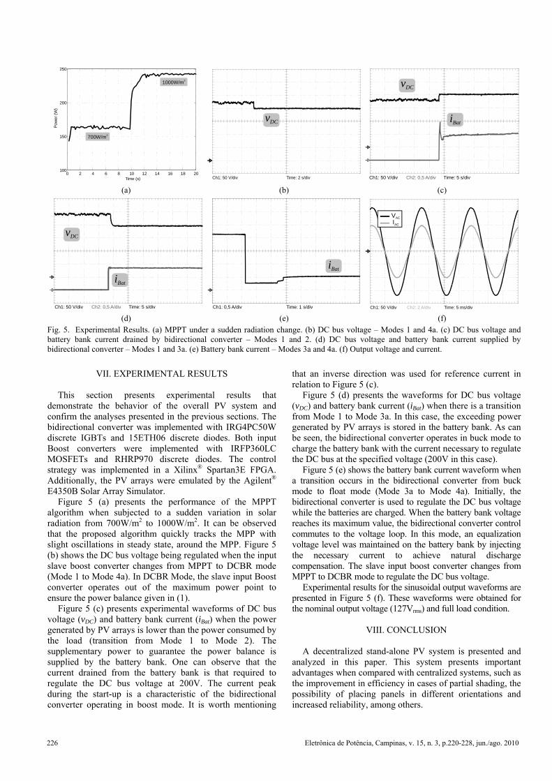
This section presents experimental results that demonstrate the behavior of the overall PV system and confirm the analyses presented in the previous sections. The bidirectional converter was implemented with IRG4PC50W discrete IGBTs and 15ETH06 discrete diodes. Both input Boost converters were implemented with IRFP360LC MOSFETs and RHRP970 discrete diodes. The control strategy was implemented in a Xilinx® Spartan3E FPGA. Additionally, the PV arrays were emulated by the Agilent® E4350B Solar Array Simulator.
Figure 5 (a) presents the performance of the MPPT algorithm when subjected to a sudden variation in solar radiation from 700W/m2 to 1000W/m2. It can be observed that the proposed algorithm quickly tracks the MPP with slight oscillations in steady state, around the MPP. Figure 5 (b) shows the DC bus voltage being regulated when the input slave boost converter changes from MPPT to DCBR mode (Mode 1 to Mode 4a). In DCBR Mode, the slave input Boost converter operates out of the maximum power point to ensure the power balance given in (1).
Figure 5 (c) presents experimental waveforms of DC bus voltage (vDC) and battery bank current (iBat) when the power generated by PV arrays is lower than the power consumed by the load (transition from Mode 1 to Mode 2). The supplementary power to guarantee the power balance is supplied by the battery bank. One can observe that the current drained from the battery bank is that required to regulate the DC bus voltage at 200V. The current peak during the start-up is a characteristic of the bidirectional converter operating in boost mode. It is worth mentioning
that an inverse direction was used for reference current in relation to Figure 5 (c).
Figure 5 (d) presents the waveforms for DC bus voltage (vDC) and battery bank current (iBat) when there is a transition from Mode 1 to Mode 3a. In this case, the exceeding power generated by PV arrays is stored in the battery bank. As can be seen, the bidirectional converter operates in buck mode to charge the battery bank with the current necessary to regulate the DC bus at the specified voltage (200V in this case).
Figure 5 (e) shows the battery bank current waveform when a transition occurs in the bidirectional converter from buck mode to float mode (Mode 3a to Mode 4a). Initially, the bidirectional converter is used to regulate the DC bus voltage while the batteries are charged. When the battery bank voltage reaches its maximum value, the bidirectional converter control commutes to the voltage loop. In this mode, an equalization voltage level was maintained on the battery bank by injecting the necessary current to achieve natural discharge compensation. The slave input boost converter changes from MPPT to DCBR mode to regulate the DC bus voltage.
Experimental results for the sinusoidal output waveforms are presented in Figure 5 (f). These waveforms were obtained for the nominal output voltage (127Vrms) and full load condition.
VIII. CONCLUSION
A decentralized stand-alone PV system is presented and
analyzed in this paper. This system presents important advantages when compared with centralized systems, such as the improvement in efficiency in cases of partial shading, the possibility of placing panels in different orientations and increased reliability, among others.
Time (s)
Pow
er (W
)
0 2 4 6 8 10 12 14 16 18 20100
150
200
250
700W/m2
1000W/m2
Ch1: 50 V/div Time: 2 s/div
vDC
Ch1: 50 V/div Ch2: 0,5 A/div Time: 5 s/div
vDC
iBat
(a) (b) (c)
Ch1: 50 V/div Ch2: 0,5 A/div Time: 5 s/div
vDC
iBat
Ch1: 0,5 A/div Time: 1 s/div
iBat
Ch1: 50 V/div Ch2: 2 A/div Time: 5 ms/div
VAC
IAC
(d) (e) (f) Fig. 5. Experimental Results. (a) MPPT under a sudden radiation change. (b) DC bus voltage – Modes 1 and 4a. (c) DC bus voltage and battery bank current drained by bidirectional converter – Modes 1 and 2. (d) DC bus voltage and battery bank current supplied by bidirectional converter – Modes 1 and 3a. (e) Battery bank current – Modes 3a and 4a. (f) Output voltage and current.
226 Eletrônica de Potência, Campinas, v. 15, n. 3, p.220-228, jun./ago. 2010
However, the proposed topology requires a more complex overall power management strategy to control power flows among PV arrays, battery bank, and inverter in order to maintain the DC bus regulation. The control strategy used was validated by simulation and experimental results. A control scheme was proposed for each individual power electronic interfacing converter. In order to extract the maximum power available from the PV arrays, an individual MPPT algorithm based on the modified P&O algorithm was used for each PV array. The IU charging method was chosen to control the battery bank charging current, which maximizes the lifetime of the batteries.
Simulation and experimental results were provided to validate the system operation in different operating modes. As the focus of this paper is to present and analyze the behavior of the decentralized PV system under different load and radiation conditions, the efficiency analysis of the converters was not addressed.
ACKNOWLEDGEMENT
The authors would like to thank Dr. Mário Lúcio da Silva
Martins, M.Sc. Felipe Grigoletto, M.Sc. Paulo Ficagna and Eng. Matheus Desconzi for helpful discussions in order to improve the paper, and the “Conselho Nacional de Desenvolvimento Científico e Tecnológico – CNPQ” (proc. 311096/2006-9 and 307798/2009-7) for financial support.
REFERENCES
[1]
European Photovoltaic Industry Association, “Solar generation V”, 2008.
[2]
D.C. Martins, “Conversores estáticos de potência utilizados no processamento da energia solarfotovoltaica”, in IV Conferência Internacional deAplicações Industriais, vol. 2, pp. 67-77, 2000.
[3]
J.H.R. Enslin, M. S. Wolf, D. B. Snyman, andW. Swiegers, “Integrated photovoltaic maximumPower point tracking converter”, IEEE Transactions onIndustrial Electronics, vol. 44, no. 6, pp. 769-773, 1997.
[4]
G. F. Rodrigues, “Estudo sobre baterias para aplicação em sistemas fotovoltaicos isolados”, Relatório InternoGEPOC-UFSM, 2005.
[5]
International Energy Agency, “Management of storage batteries used in stand-alone photovoltaic power systems”, Report_IEA_PVPS_T3-10:2002, 2002.
[6]
B. Lindgren, “A power converter for photovoltaic applications”, Technical Report no. 335L, Chalmers University of Technology, Göteborg, Sweden, 2000.
[7]
M. Meinhardt and G. Cramer, “Multi-string converter: the next step in evolution of string-converter technology”, in 9th European Conference on PowerElectronics and Applications, 2001.
[8]
M. Calais, J. Myrzik, T. Spooner, and V. G. Agelidis, “Inverters for single-phase grid connected photovoltaicsystems – an overview,” in 33rd IEEE Power Electronics Specialists Conference, vol. 4, pp. 1995-2000, 2002.
[9]
J. Myrzik and M. Calais, “String and module integrated inverters for single-phase grid connected photovoltaic systems – a review,” in IEEE Bologna Power Tech Conference Proceedings, vol. 2, 2003.
[10]
F. Blaabjerg, Z. Chen, and S. B. Kjaer, “Power electronics as efficient interface in dispersed power generation systems”, IEEE Transactions on PowerElectronics, vol. 19, no. 5, pp. 1184-1194, 2004.
[11]
G. R. Walker and P. C. Sernia, “Cascaded DC-DC converter connection of photovoltaic modules”, IEEE Transactions on Power Electronics, vol. 19, no. 4,pp. 1130-1139, 2004.
[12]
G. R. Walker and J. C. Pierce, “Photovoltaic DC-DC module integrated converter for novel cascaded and bypass grid connection topologies”, in 37th IEEE Power Electronics Specialist Conference, pp. 3094-3100, 2006.
[13]
S. B. Kjaer, J. K. Pedersen, and F. Blaabjerg, “A review of single-phase grid-connected inverters for photovoltaic modules”, IEEE Transactions on IndustryApplications, vol. 41, no. 5, pp. 1292-1305, 2005.
[14]
G. R. Walker and P. C. Sernia, “Cascaded DC-DC converter connection of photovoltaic modules”, IEEE Transactions on Power Electronics, vol. 19, no. 4, pp. 1130-1139, 2004.
[15]
J. Imhoff, J. R. Pinheiro, J. L. Russi, D. Brum, R. Gules and H. L. Hey, “DC-DC Converters in a multi-string configuration for stand-alone photovoltaic systems”, in39th IEEE Power Electronics Specialists Conference, pp. 2806-2812, 2008.
[16] P. C. Sernia and G. R. Walker, “Multi-converter topology evaluation for connection of low voltage DC sources”, in Australasian Universities Power Engineering Conference, vol. 1, pp. 495-500, 2001.
[17] L. Schuch, C. Rech, H. L. Hey, H. A. Gründling, H. Pinheiro, and J. R. Pinheiro, “Analysis and design of a new high-efficiency bidirectional integrated ZVT PWM converter for DC-bus and battery-bank interface”, IEEE Transaction on Industry Applications, vol. 42, no. 5, pp. 1321-1332, 2006.
[18] L. Schuch, “Sistema CA/CC com um conversor PWM bidirecional para interface entre o barramento CC e o banco de baterias” (Master Thesis), Programa de Pós Graduação em Engenharia Elétrica, Universidade Federal de Santa Maria, 2001.
[19] T. Esram and P.L Chapman, “Comparison of photovoltaic array maximum power point tracking techniques”, IEEE Transactions on Energy Conversion, vol. 22, no. 2, pp. 439-449, 2007.
Eletrônica de Potência, Campinas, v. 15, n. 3, p.220-228, jun./ago. 2010 227
BIOGRAPHIES
Diogo B. Cândido was born in Porto Alegre, RS, Brazil, in 1985. He received the B.S. and M.S degrees in electrical engineering from the Federal University of Santa Maria, Santa Maria, Brazil, in 2007 and 2010, respectively. From 2004 to 2010, he was with the Power Electronics and Control Research Group (GEPOC), Federal University of Santa Maria. Currently, he is Product Development Engineer with WEG S.A., Jaraguá do Sul, Brazil. His research interests include power electronics, frequency AC motor drivers and renewable energy applications.
Jonatan Rafael Rakoski Zientarski was born in Ijuí, Brazil. He received the B.S. degree in electrical engineering from the Regional University of Northwest Rio Grande do Sul State, Brazil, in 2006 and the M.S. degree in electrical engineering at the Federal University from Santa Maria, Brazil, in 2009. Since 2010, he has been with Instituto Federal Catarinense, where he is currently a Professor. His research interests include power converters modeling, design and optimization, power factor correction and EMI suppression techniques.
Rafael Concatto Beltrame was born in Santa Maria, Brazil, in 1984. He received the B.S. and M.S. degrees in electrical engineering from the Federal University of Santa Maria, Brazil, in 2008 and 2009, respectively, where he is currently working toward the Ph.D. degree. Since 2005, he has been with the Power Electronics and Control Research Group (GEPOC), Federal University of Santa Maria. His research interests include electric motor drives, high-performance power converters, and soft-switching techniques.
José Renes Pinheiro was born in Santa Maria, Brazil,
1958. He received the B.S. degree from the Federal University of Santa Maria, Santa Maria, Brazil, in 1981, and the M.S. and Ph.D. degrees from the Federal University of Santa Catarina, Florianópolis, Brazil, in 1984 and 1994, respectively, all in electrical engineering. His current research interests include high-frequency and high-power conversion, power supplies, multilevel converters, power-factor-correction techniques, and modeling and control of converters.
Leandro Michels was born in Não-Me-Toque, Brazil, in 1979. He received the B.S and Ph.D. degrees from the Federal University of Santa Maria, Santa Maria, Brazil, in 2002 and 2006, respectively, both in electrical engineering. Since 2009 he has been with the Power Electronics and Control Research Group (GEPOC) at Federal University of Santa Maria, where he is currently an Adjunct Professor. His current research interests include modeling and control of power converters, applied digital control and renewable energy applications.
Hélio Leães Hey was born in Santa Maria, Brazil, in 1961. He received the B.S. degree from the Catholic University of Pelotas, Pelotas, Brazil, in 1985, and the M.S. and Ph.D. degrees from the Federal University of Santa Catarina, Florianópolis, Brazil, in 1987 and 1991, respectively. Since 1994, he has been with the Power Electronics and Control Research Group (GEPOC), Federal University of Santa Maria, where he is currently a Full Professor.
228 Eletrônica de Potência, Campinas, v. 15, n. 3, p.220-228, jun./ago. 2010