Impedance relay and protection RXZK 21H, 22H, … impedance relay, type RXZK 2H, ... (0,1 0,2 0,4...
20
Page 1 Features • Micro-processor based impedance relay with R and X settings for operate values and built in time delay functions • Characteristic angle settable 0° to 120° • Three variants with wide setting ranges: - RXZK 21H: one zone + time function - RXZK 22H: two impedance measuring zones - RXZK 23H: one zone + out-of-step function • Definite time delay settable 0,1-5 s on second measuring stage • Directional function with settable characteristic angle 0° to +120° and memory • Assemblies • Independent measuring elements with indications built in • Test switch and heavy-duty start and trip output contacts are available as options Application The RXZK family of single phase directional and non directional impedance relays are intended for general purpose use in power systems as primary or back-up functions often in combination with other protective relays. The quadrilateral impedance reach characteristic is independently adjustable in the reactive and resistive direction. Forward, reverse and non directional functions are available. Applications of RXZK 21 and 22H include single zone and two zone impedance protection of transformers, generators, lines and cables. Where it is necessary to obtain the same reach for two-phase and three-phase faults the relay assembly should be connected to measure delta-current i.e. I R -I S and phase to phase voltage i.e. U R -U S for each measur- ing elements respectively. The delta current can be derived using a auxiliary CT’s or sometimes by connecting the main CT in delta (e.g together with the transformer dif- ferential relays. The RXZK 23H is intended for detecting out of step conditions for tie- lines and synchronous generators and motors. The RXZK 23H includes a current reversal logic in order to set up a trip condition. This ensures that the relay will not trip on stable swing conditions, i.e. swings not resulting in a current reversal. (SE970175) (SE970184) Impedance relay and protection assemblies RXZK 21H, 22H, 23H and RAZK 1MRK 509 006-BEN Issued June 1999 Changed since July 1998 Data subject to change without notice
Transcript of Impedance relay and protection RXZK 21H, 22H, … impedance relay, type RXZK 2H, ... (0,1 0,2 0,4...

Page 1
rs.
(SE970175) (SE970184)
Impedance relay and protection assemblies
RXZK 21H, 22H,23H and RAZK
1MRK 509 006-BEN
Issued June 1999Changed since July 1998
Data subject to change without notice
Features • Micro-processor based impedance relay with R and X settings for operate values and built in time delay functions
• Characteristic angle settable 0° to 120°
• Three variants with wide setting ranges:
- RXZK 21H: one zone + time function
- RXZK 22H: two impedance measuring zones
- RXZK 23H: one zone + out-of-stepfunction
• Definite time delay settable 0,1-5 s on second measuring stage
• Directional function with settablecharacteristic angle 0° to +120° andmemory
• Assemblies
• Independent measuring elements with indications built in
• Test switch and heavy-duty start and trip output contacts are available as options
Application The RXZK family of single phase directional and non directional impedance relays are intended for general purpose use in power systems as primary or back-up functions often in combination with other protective relays. The quadrilateral impedance reach characteristic is independently adjustable in the reactive and resistive direction. Forward, reverse and non directional functions are available. Applications of RXZK 21 and 22H include single zone and two zone impedance protection of transformers, generators, lines and cables. Where it is necessary to obtain the same reach for two-phase and three-phase faults the relay assembly should be connected
to measure delta-current i.e. IR-IS and phase to phase voltage i.e. UR-US for each measur-ing elements respectively. The delta current can be derived using a auxiliary CT’s or sometimes by connecting the main CT in delta (e.g together with the transformer dif-ferential relays. The RXZK 23H is intended for detecting out of step conditions for tie-lines and synchronous generators and motoThe RXZK 23H includes a current reversal logic in order to set up a trip condition. This ensures that the relay will not trip on stable swing conditions, i.e. swings not resulting ina current reversal.
Impedance relay and protection assemblies
RXZK 21H, 22H, 23Hand RAZK
1MRK 509 006-BENPage 2
g by
t
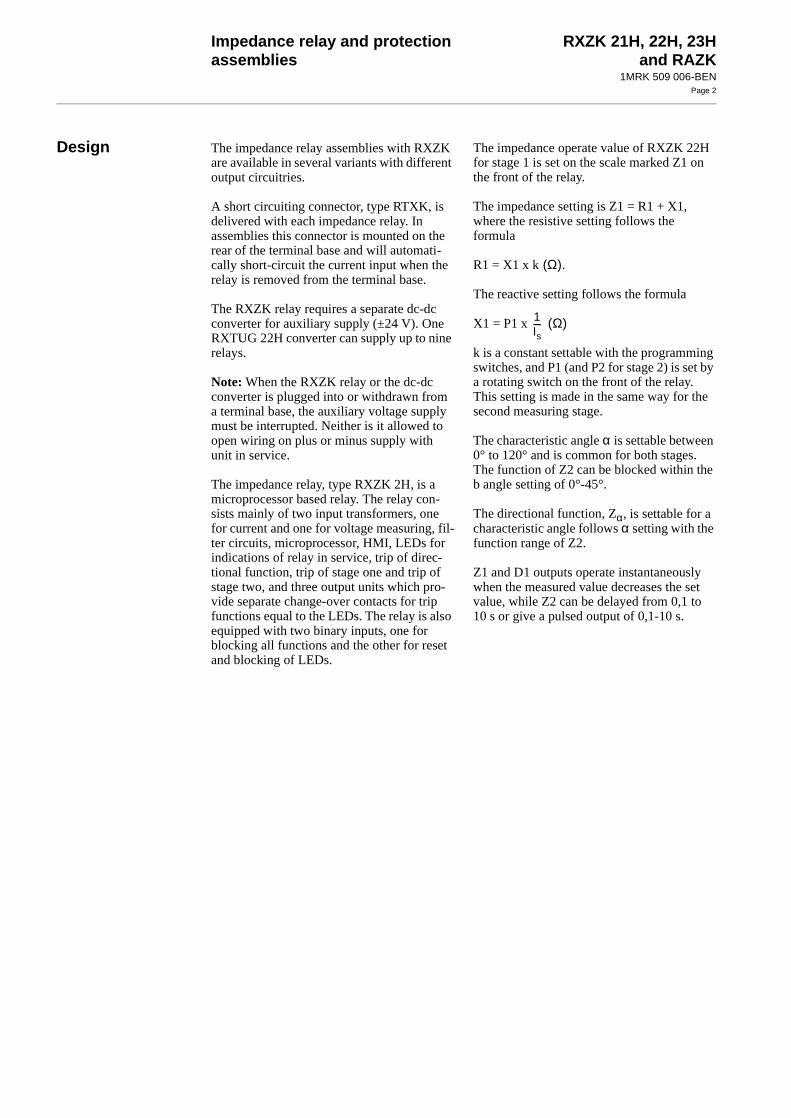
Design The impedance relay assemblies with RXZK are available in several variants with different output circuitries.
A short circuiting connector, type RTXK, is delivered with each impedance relay. In assemblies this connector is mounted on the rear of the terminal base and will automati-cally short-circuit the current input when the relay is removed from the terminal base.
The RXZK relay requires a separate dc-dc converter for auxiliary supply (±24 V). One RXTUG 22H converter can supply up to nine relays.
Note: When the RXZK relay or the dc-dc converter is plugged into or withdrawn from a terminal base, the auxiliary voltage supply must be interrupted. Neither is it allowed to open wiring on plus or minus supply with unit in service.
The impedance relay, type RXZK 2H, is a microprocessor based relay. The relay con-sists mainly of two input transformers, one for current and one for voltage measuring, fil-ter circuits, microprocessor, HMI, LEDs for indications of relay in service, trip of direc-tional function, trip of stage one and trip of stage two, and three output units which pro-vide separate change-over contacts for trip functions equal to the LEDs. The relay is also equipped with two binary inputs, one for blocking all functions and the other for reset and blocking of LEDs.
The impedance operate value of RXZK 22Hfor stage 1 is set on the scale marked Z1 onthe front of the relay.
The impedance setting is Z1 = R1 + X1,where the resistive setting follows the formula
R1 = X1 x k (Ω).
The reactive setting follows the formula
X1 = P1 x (Ω)
k is a constant settable with the programminswitches, and P1 (and P2 for stage 2) is set a rotating switch on the front of the relay. This setting is made in the same way for thesecond measuring stage.
The characteristic angle α is settable between 0° to 120° and is common for both stages. The function of Z2 can be blocked within theb angle setting of 0°-45°.
The directional function, Zα, is settable for a characteristic angle follows α setting with the function range of Z2.
Z1 and D1 outputs operate instantaneously when the measured value decreases the sevalue, while Z2 can be delayed from 0,1 to 10 s or give a pulsed output of 0,1-10 s.
1Is----
Impedance relay and protection assemblies
RXZK 21H, 22H, 23Hand RAZK
1MRK 509 006-BENPage 3
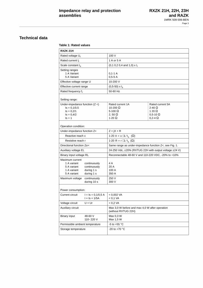
Technical data
Table 1: Rated values
RXZK 21H
Rated voltage Ur 100 V
Rated current Ir 1 A or 5 A
Scale constant Is (0,1 0,2 0,4 and 1,0) x Ir
Setting ranges1 A Variant5 A Variant
0,1-1 A0,5-5 A
Effective voltage range U 10-200 V
Effective current range (0,5-50) x Is
Rated frequency fr 50-60 Hz
Setting range:
Under-impedance function (Z <)Is = 0,1/0,5Is = 0,2/1Is = 0,4/2Is = 1
Rated current 1A10-200 Ω5-100 Ω2, 50 Ω1-20 Ω
Rated current 5A2-40 Ω1 20 Ω0,5-10 Ω0,2-4 Ω
Operation condition:
Under-impedance function Z< Z = jX + R
Reactive reach x 1-20 (Ω)
Resistive reach r 1-20 (Ω)
Directional function Zα< Same range as under-impedance function Z<, see Fig. 1.
Auxiliary voltage EL 24-250 Vdc, ±20% (RXTUG 22H with output voltage ±24 V)
Binary input voltage RL Reconnectable 48-60 V and 110-220 VDC, -20% to +10%
Maximum current1 A variant continuously5 A variant continuously1 A variant during 1 s5 A variant during 1 s
4 A20 A100 A350 A
Maximum voltage continuouslyduring 10 s
250 V300 V
Power consumption:
Current circuit I = Is = 0,1/0,5 AI = Is = 1/5A
< 0,002 VA< 0,1 VA
Voltage circuit U = Ur < 0,2 VA
Auxiliary circuit Max 3,0 W before and max 4,0 W after operation(without RXTUG 22H)
Binary input 48-60 V110- 220 V
Max 0,3 WMax 1,5 W
Permissible ambient temperature -5 to +55 °C
Storage temperature -20 to +70 °C
X x= 1 Is⁄⋅
R r= 1 Is⁄⋅

Impedance relay and protection assemblies
RXZK 21H, 22H, 23Hand RAZK
1MRK 509 006-BENPage 4
Technical data (cont’d)Technical data (cont’d)
Impedance function Z< Zα<
Operate time (typical) 50 ms 50 ms
Reset time (typical) 50 ms 50 ms
Reset ratio (typical) 110% 110%
Time function
Time delay Definite time –
Setting range 0-5 s –
Settings:
Reactive reach x = 10 Reactive reach x = 10
Resistive reach r = 10 Resistive reach r = 10
α = 90° α = 60°
Z <, Under-impedance function
Zα <, Directional under-impedance function
Fig. 1 Characteristic for the under-impedance function
Table 1: Rated values
R
X
x
rα R
X
x
r
α
R
X
x
αr R
X
x
r
α

Impedance relay and protection assemblies
RXZK 21H, 22H, 23Hand RAZK
1MRK 509 006-BENPage 5
RXZK 22H
Rated voltage Ur 100 V
Rated current Ir 1 A or 5 A
Scale constant Is (0,1 0,2 0,4 and 1,0) x Ir
Setting ranges 1 A Variant5 A Variant
0,1-1 A0,5-5 A
Effective voltage range U 10-200 V
Effective current range (0,5-50) x Is
Rated frequency fr 50-60 Hz
Characteristic angle α 0-120°, see Fig. 1
Characteristic angle β 0, 15, 30 and 45°, see Fig. 1
Setting range for Z1< and Z2< Rated current 1A Rated current 5A
Under-impedance function X-axis R-axis X-axis R-axis
Is = 0,1 / 0,5Is = 0,2 / 1Is = 0,4 / 2Is = 1 / 5
20-100 Ω10-50 Ω5-25 Ω2-10 Ω
12-200 Ω6-100 Ω3-50 Ω1,2-20 Ω
4-20 Ω2-10 Ω1-5 Ω0,4- 2 Ω
2,4-40 Ω1,2-20 Ω0,6-10 Ω0,24-4 Ω
Operation conditions:
Under-impedance zone 1 Z1 = jX1 + R1
Z1< non-directionalSetting range P1Reactive reach xResistive reach rConstant k
Instantaneous operation2-10X1 = P1 x 1/Is (Ω)R1 = X1 x k (Ω)(0,6-2,0) x P1, in steps of 0,2
Under-impedance zone 2 Z2 = jX2 + R2
Z2< non-directional orZ2α< directional andZ2< non-directional
Setting range P2Reactive reach xResistive reach rConstant k
Instantaneous operation and time delayed operationInstantaneous operation, independent of β-angleTime delayed operation2-10X2 = P2 x 1/Is (Ω)R2 = X2 x k (Ω)(0,6-2,0) x P2, in steps of 0,2
Note The impedance reach for zone 1 should not be sethigher than zone 2
Auxiliary voltage EL 24-250 VDC, ±20% (RXTUG 22H with output voltage ±24 V)
Binary input voltage RL Reconnectable 48-60 V and 110-220 VDC, -20% to +10%
Maximum current1 A variant continuously5 A variant continuously1 A variant during 1 s5 A variant during 1 s
4 A20 A100 A350 A
Maximum voltage continuouslyduring 10 s
250 V300 V
Power consumption:
Current circuit I = Is = 0,1/0,5 AI = Is = 1/5 A
< 0,002 VA< 0,1 VA
Voltage circuit U = Ur < 0,2 VA
Auxiliary circuit Max 3,0 W before and max 4,0 W after operation(without RXTUG 22H)
Table 1: Rated values

Impedance relay and protection assemblies
RXZK 21H, 22H, 23Hand RAZK
1MRK 509 006-BENPage 6
Technical data (cont’d)Technical data (cont’d)
Binary input 48-60 V110- 220 V
Max 0,3 WMax 1,5 W
Permissible ambient temperature -5 to +55 °C
Storage temperature -20 to +70 °C
Impedance function Z1 < Z2 < Z2α <
Operate time (typical) 50 ms 50 ms 50 ms
Reset time (typical) 50 ms 50 ms 50 ms
Reset ratio (typical) 110% 110% 110%
Time function
Time delay – Definite time –
Setting range – 0 - 5 s –
Table 1: Rated values
Impedance relay and protection assemblies
RXZK 21H, 22H, 23Hand RAZK
1MRK 509 006-BENPage 7
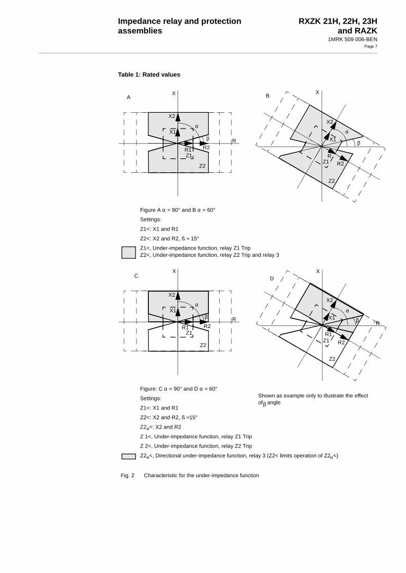
Figure A α = 90° and B α = 60°
Settings:
Z1<: X1 and R1
Z2<: X2 and R2, ß ≈ 15°
Z1<, Under-impedance function, relay Z1 TripZ2<, Under-impedance function, relay Z2 Trip and relay 3
Figure: C α = 90° and D α = 60°Shown as example only to illustrate the effectof β angle
Settings:
Z1<: X1 and R1
Z2<: X2 and R2, ß ≈15°
Z2α<: X2 and R2
Z 1<, Under-impedance function, relay Z1 Trip
Z 2<, Under-impedance function, relay Z2 Trip
Z2α<, Directional under-impedance function, relay 3 (Z2< limits operation of Z2α<)
Fig. 2 Characteristic for the under-impedance function
Table 1: Rated values
R
X
Z2
β
α
Z1
X2
R2
X1
R1
A
α
β
X
X2
R2
Z2
Z1
X1
R
B
R
X
Z2
β
α
Z1
X2
R2
X1
R1
C
α
β R
X
X2
R2
Z2
Z1
X1
R1
D
Impedance relay and protection assemblies
RXZK 21H, 22H, 23Hand RAZK
1MRK 509 006-BENPage 8
Technical data (cont’d)Technical data (cont’d)
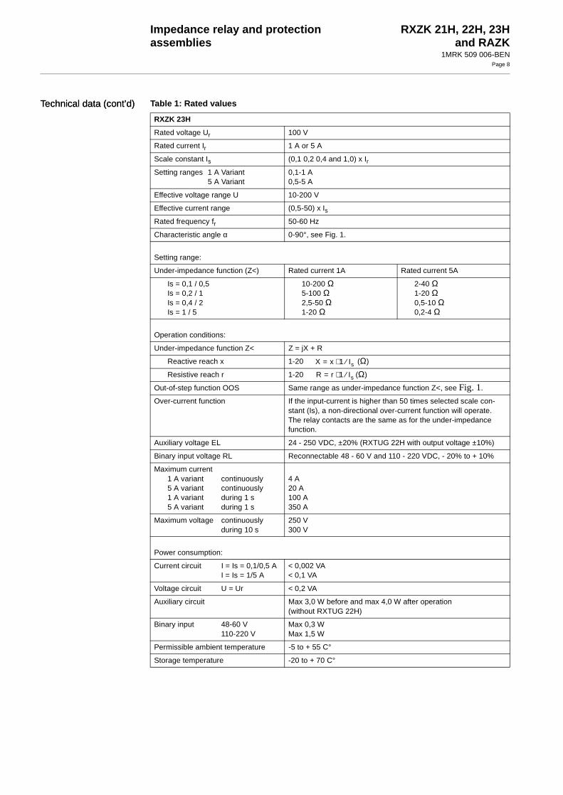
RXZK 23H
Rated voltage Ur 100 V
Rated current Ir 1 A or 5 A
Scale constant Is (0,1 0,2 0,4 and 1,0) x Ir
Setting ranges 1 A Variant5 A Variant
0,1-1 A0,5-5 A
Effective voltage range U 10-200 V
Effective current range (0,5-50) x Is
Rated frequency fr 50-60 Hz
Characteristic angle α 0-90°, see Fig. 1.
Setting range:
Under-impedance function (Z<) Rated current 1A Rated current 5A
Is = 0,1 / 0,5Is = 0,2 / 1Is = 0,4 / 2Is = 1 / 5
10-200 Ω5-100 Ω2,5-50 Ω1-20 Ω
2-40 Ω1-20 Ω0,5-10 Ω0,2-4 Ω
Operation conditions:
Under-impedance function Z< Z = jX + R
Reactive reach x 1-20 (Ω)
Resistive reach r 1-20 (Ω)
Out-of-step function OOS Same range as under-impedance function Z<, see Fig. 1.
Over-current function If the input-current is higher than 50 times selected scale con-stant (Is), a non-directional over-current function will operate. The relay contacts are the same as for the under-impedance function.
Auxiliary voltage EL 24 - 250 VDC, ±20% (RXTUG 22H with output voltage ±10%)
Binary input voltage RL Reconnectable 48 - 60 V and 110 - 220 VDC, - 20% to + 10%
Maximum current1 A variant continuously5 A variant continuously1 A variant during 1 s5 A variant during 1 s
4 A20 A100 A350 A
Maximum voltage continuouslyduring 10 s
250 V300 V
Power consumption:
Current circuit I = Is = 0,1/0,5 AI = Is = 1/5 A
< 0,002 VA< 0,1 VA
Voltage circuit U = Ur < 0,2 VA
Auxiliary circuit Max 3,0 W before and max 4,0 W after operation(without RXTUG 22H)
Binary input 48-60 V110-220 V
Max 0,3 WMax 1,5 W
Permissible ambient temperature -5 to + 55 C°
Storage temperature -20 to + 70 C°
Table 1: Rated values
X x= 1 Is⁄⋅
R r= 1 Is⁄⋅

Impedance relay and protection assemblies
RXZK 21H, 22H, 23Hand RAZK
1MRK 509 006-BENPage 9
Impedance function Z <
Operate time (typical) 50 ms
Reset time (typical) 50 ms
Reset ratio (typical) 110%
Time function
Time delay Definite time
Setting range 0-5 s
Settings:
Reactive reach x = 10 Reactive reach x = 10
Resistive reach r = 10 Resistive reach r = 10
α = 90° α = 60°
Z <, Under-impedance function
OOS, Out-Of-Step function
In order to achieve an out-of-step trip the impedance has to leave the set impedance reach on theopposite side of the characteristic angle (α) from where the impedance entered the set impedancereach.
Fig. 3 Characteristic for the under-impedance function
Table 1: Rated values
R
X
x
rα
R
X
x
r
α

Impedance relay and protection assemblies
RXZK 21H, 22H, 23Hand RAZK
1MRK 509 006-BENPage 10
Technical data (cont’d)
Table 2: Insulation tests
RXZK 21H, RXZK 22H, RXZK 23H Type test values Ref. Standard
Dielectric test open circuitother circuitoverall open circuit
2,5 kV ac 1 min.2,0 kV ac 1 min.1,0 kV ac 1 min.
IEC 60255-5
Impulse voltage test 5 kV 1,2 µs, 0,5 J IEC 60255-5
Insulation resistance > 100 MΩ at 500 V DC IEC 60255-5
Table 3: Immunity tests
RXZK 21H, RXZK 22H, RXZK 23H Type test values Ref. Standard
Surge Immunity test Differential 2 kVCommon 4 kVDifferential 1 kVCommon 2 kV
IEC 801-5 class 4
IEC 801-5 class 3
AC injection test 500 V CC = 10 nF differential modeC = 100 nF common mode
SS 436 15 03 PL 4
Power frequency magnetic fieldImmunity test
Magnetic field 1000 A/mX, Y, Z-axis 3s
EN 61000-4-8
1MHz burst disturbance test 2,5 kV IEC 60255-22-1 class 3
Spark test 4-8 kV SS 436 15 03 PL4
Fast transient tests 4 kV IEC 60255-22-4 class 4
Electric discharge test with cover on class 4
8 kV (contact discharge)15 kV (air discharge)8 kV Indirect application
IEC 60255-22-2
IEC 61000-4-2
Radiated electromagnetic field disturbance test
10 V/m 26-1000 MHz EN 50082-2
Conducted electromagnetic disturbance test
0,15-80 MHz EN 50082-2
Interruption in auxiliary voltage 2-200 msNo setting for interruptions< 40 ms
IEC 60255-11
Table 4: Electromagnetic tests
RXZK 21H, RXZK 22H, RXZK 23H Type test values Ref. Standard
Electromagnetic emission, conducted 0,15-30 MHz class A EN 50081-2
Electromagnetic emission, radiated 30-1000 MHZ class A EN 50081-2

Impedance relay and protection assemblies
RXZK 21H, 22H, 23Hand RAZK
1MRK 509 006-BENPage 11
Table 5: Mechanical tests
RXZK 21H, RXZK 22H, RXZK 23H Type test values Ref. Standard
Vibration test Response testEndurance test
2,0 g, 10-150 Hz1 g, 10-150 Hz, 20 sweeps
IEC 60255-21-1, class IIIEC 60255-21-1, class I
Shock tests Response testEndurance test
5 g, 11 ms, 3 pulses15 g, 11 ms, 3 pulses
IEC 60255-21-2, class IIEC 60255-21-2, class I
Bump test 10 g, 16 ms, 1000 pulses IEC 60255-21-2, class I
Seismic tests X-axisY-axisZ-axis
3 g, 1-35 Hz3 g, 1-35 Hz2 g, 1-35 Hz
IEC 60255-21-3, class IIIEC 60255-21-3, class IIIEC 60255-21-3, class II
Table 6: Contact data
RXZK 21H, RXZK 22H, RXZK 23H Type test values
Highest system voltage 250 V ac, dc
Current carrying capacity continuousduring 1 s
5 A15 A
Making and conducting capacity during 0,2 sduring 1 s
30 A10 A
Breaking capacity ac, cos ϕ >0,4, 250 Vdc, L/R, < 40 ms
48 V110 V220 V250 V
8 A
1,0 A0,4 A0,2 A0,15 A
Table 7: Additional general data
RXZK 21H, RXZK 22H, RXZK 23H Type test values
Dimensions 4U 6C
Weight 0,7 kg

Impedance relay and protection assemblies
RXZK 21H, 22H, 23Hand RAZK
1MRK 509 006-BENPage 12
Diagrams
Fig. 7 Terminal diagram 1MRK 001 030-EAA
Fig. 4 Terminal diagram for RXZK 21H Fig. 5 Terminal diagram for RXZK 22H Fig. 6 Terminal diagram for RXZK 23H
0V+24V -24V
EL
114 115 116
316 317318
331
341
Ir
0A
Z< Trip 2
Ir
313 314315
323
325
100V
0V
Z< Trip 1
Ur
110-220V
48-60V
0VRL 112 122 48-60V
113 123 0VRL
111 121 110-220V
Bin 1 Bin 2
326 327328
117Z< /Zα > Start
(970
0038
4)
0V+24V -24V
EL
114 115 116
316 317318
331
341
Ir
0A
Z2 Trip
Ir
313 314315
323
325
120V
0V
Z1 Trip
Ur
110-220V
48-60V
0VRL 112 122 48-60V
113 123 0VRL
111 121 110-220V
Bin 1 Bin 2
326 327328
117Z2</Z2α< Start
(970
0038
5)
0V+24V -24V
EL
114 115 116
316 317318
331
341
Ir
0A
Z<
Ir
313 314315
323
325
100V
0V
Z<
Ur
110-220V
48-60V
0VRL 112 122 48-60V
113 123 0VRL
111 121 110-220V
Bin 1 Bin 2
326 327328
117OOS
(970
0038
6)

Impedance relay and protection assemblies
RXZK 21H, 22H, 23Hand RAZK
1MRK 509 006-BENPage 13
Fig. 8 Terminal diagram 1MRK 001 030-ZAA
Fig. 9 Terminal diagram 1MRK 001 065-EAA

Impedance relay and protection assemblies
RXZK 21H, 22H, 23Hand RAZK
1MRK 509 006-BENPage 14
Diagrams (cont’d)
Fig. 10 Terminal diagram 1MRK 001 065-ZAA
Fig. 11 Terminal diagram 1MRK 001 068-EAA

Impedance relay and protection assemblies
RXZK 21H, 22H, 23Hand RAZK
1MRK 509 006-BENPage 15
Fig. 12 Terminal diagram 1MRK 001 030-ZBA
Fig. 13 Terminal diagram 1MRK 001 065-ZBA

Impedance relay and protection assemblies
RXZK 21H, 22H, 23Hand RAZK
1MRK 509 006-BENPage 16
Protectionassemblies
RAZK Protection assemblies are built up based upon impedance relay RXZK 2H. Test device RXTP 18 and dc/dc-converter RXTUG 22H can also be included for specific application require-ments. Test device RTXP 18 is a tool for relay testing.
DC/DC-converter RXTUG 22H can be used either separately for a single protection or to feed also other protections with up to 9 units of the same relay family. With RXTUG 22H all requirements concerning disturbance emission and immunity with this protection assembly will be met.
The assemblies have output contacts as speci-fied for the relay RXZK 2H, which in most cases are fully sufficient.
Protections are normally available with out-put logic with heavy duty relay RXME 18 (RK 221 825-XX) with indicating flag and can upon request be completed with an output logic of free choice. Output relays are con-nected to separate auxiliary voltage.
The extremely flexible mounting system COMBIFLEX together with a modern CAD-system enables us to present a unique flexi-bility for designing assemblies upon the cus-tomers requests.
The interface voltage for enable or block impulses can be connected to either 48-60 V dc or 110-220 V dc by connecting the volt-age circuit to separate terminals. At delivery all relays are connected for 110-220 V dc.
RAZK 1 Single-element impedance protection
101 RTXP 18 101 RXTUG 22H 101 RTXP 18 101 RTXP 18
107 RXZK 107 RXZK 107 RXTUG 22H 107 RXTUG 22H
113 RXZK 113 RXZK
119 RXME 18
319 RXME 18
Order No. Circuitdiagram
Order No. Circuitdiagram
Order No. Circuitdiagram
Order No. Circuitdiagram
RAZK 211 (1 RXZK 21H)1MRK001 029-BA
1MRK001 030-BA
1MRK001 029-CA
1MRK001 030-CA
1MRK001 029-DA
1MRK001 030-DA
1MRK001 029-EA
1MRK001 030-EA
RAZK 221 (1 RXZK 22H)1MRK001 064-BA
1MRK001 065-BA
1MRK001 064-CA
1MRK001 065-CA
1MRK001 064-DA
1MRK001 065-DA
1MRK001 064-EA
1MRK001 065-EA
RAZK 231 (1 RXZK 23H)1MRK001 067-BA
1MRK001 068-BA
1MRK001 067-CA
1MRK001 068-CA
1MRK001 067-DA
1MRK001 068-DA
1MRK001 067-EA
1MRK001 068-EA
I >
49
1=> 0
107101 107101 113107101
319
119113107101

Impedance relay and protection assemblies
RXZK 21H, 22H, 23Hand RAZK
1MRK 509 006-BENPage 17
RAZK 2 Two-element impedance protection without auxiliary CTs
101 RTXP 18 101 RXTUG 22H 101 RTXP 18 101 RTXP 18
107 RXZK 107 RXZK 107 RXTUG 22H 107 RXTUG 22H
113 RXZK 113 RXZK 113 RXZK 113 RXZK
119 RXZK 119 RXZK
125 XME 18
325 RXME 18
Order No. Circuitdiagram
Order No. Circuitdiagram
Order No. Circuitdiagram
Order No. Circuitdiagram
RAZK 212 (2 RXZK 21H)1MRK001 029-GA
1MRK001 030-GA
1MRK001 029-HA
1MRK001 030-HA
1MRK001 029-KA
1MRK001 030-KA
1MRK001 029-LA
1MRK001 030-LA
RAZK 222 (2 RXZK 22H)1MRK001 064-GA
1MRK001 065-GA
1MRK001 064-HA
1MRK001 065-HA
1MRK001 064-KA
1MRK001 065-KA
1MRK001 064-LA
1MRK001 065-LA
249
1=> 0
107101 113 107101 113 113107101 119
325
125107101 119113
RAZK 3 Three-element impedance protection without auxiliary CTs
101 RTXP 18 101 RXTUG 22H 101 RTXP 18 101 RTXP 18
107 RXZK 107 RXZK 107 RXTUG 22H 107 RXTUG 22H
113 RXZK 113 RXZK 113 RXZK 113 RXZK
119 RXZK 119 RXZK 119 RXZK 119 RXZK
125 RXZK 125 RXZK
131 RXME 18
331 RXME 18
Order No. Circuitdiagram
Order No. Circuitdiagram
Order No. Circuitdiagram
Order No. Circuitdiagram
RAZK 211 (3 RXZK 21H)1MRK001 029-NA
1MRK001 030-NA
1MRK001 029-YA
1MRK001 030-YA
1MRK001 029-PA
1MRK001 030-PA
1MRK001 029-ZA
1MRK001 030-ZA
RAZK 221 (3 RXZK 22H)1MRK001 064-NA
1MRK001 065-NA
1MRK001 064-YA
1MRK001 065-YA
1MRK001 064-PA
1MRK001 065-PA
1MRK001 064-ZA
1MRK001 065-ZA
349
1=> 0
107101 113 119 107101 113 119 113107101 119 125
331
131107101 113 119 125

Impedance relay and protection assemblies
RXZK 21H, 22H, 23Hand RAZK
1MRK 509 006-BENPage 18
Protection assemblies (cont’d)
Mountingalternatives
All assemblies can be delivered in the following mounting alternatives:
- on apparatus bars
- in equipment frame
- in RHGS
- in RHGX
RAZK 3 Three-element impedance protection with auxiliary CTs to achieve delta current
101 RTXP 18 101 RTXP 18
107 RXTUG 22H 107 RXTUG 22H
113, 125, 313 CT 113, 125, 313 CT
137, 143, 149 RXZK 137, 143, 149 RXZK 18
325, 331 RXME 18
Order No. Circuitdiagram
Order No. Circuitdiagram
RAZK 213 (3 RXZK 21H)1MRK001 029-PB
1MRK001 030-PB
1MRK001 029-ZB
1MRK001 030-ZB
RAZK 223 (3 RXZK 22H)1MRK001 064-PB
1MRK001 065-PB
1MRK001 064-ZB
1MRK001 065-ZB
349
1=> 0
107101 113 125 149143137
137
107101 113 125 149143137
313 325 331

Impedance relay and protection assemblies
RXZK 21H, 22H, 23Hand RAZK
1MRK 509 006-BENPage 19
Ordering Specify:
• Quantity
• Ordering number
• Code A, H, M
• Desired wording on the lower half of the test switch face plate max. 13 lines with 14 characters per line.
• Specify RXZK 21H, RXZK 22H and RXZK 23H (Loose Relay)
• Quantity
• Ordering number
Impedance relay
Auxiliary voltageMainly for included (auxiliary relays)
Mounting
References Connection and installation components inCOMBIFLEX 1MRK 513 003-BEN
Relay accessoriesCOMBIFLEX 1MRK 513 004-BEN
Test systemCOMBITEST 1MRK 512 001-BEN
Type Rated current Article No. Code
RXZK 21H 1 A 1MRK 000 845-AA A1
RXZK 21H 5 A 1MRK 000 845-BA A2
RXZK 22H 1 A 1MRK 000 845-CA A3
RXZK 22H 5 A 1MRK 000 845-DA A4
RXZK 23H 1 A 1MRK 000 845-EA A5
RXZK 23H 5 A 1MRK 000 845-FA A6
Code
24 V dc H5
48-55 V dc H6
110-125 V dc H7
220-250 V dc H8
Mounting alternatives Size Article No. Code
Apparatus bars M10
Equipment frame without door 4U 19” 1MRK 000 137-GA M11
Equipment frame with door 4U 19” 1MRK 000 137-KA M12
RHGX 4 4U 12C RK 927 001-AB M71
RHGX 8 4U 24C RK 927 002-AB M72
RHGX 12 4U 36C RK 927 003-AB M73
RHGX 20 4U 60C RK 927 004-AB M74
RHGS 30 6U x 1/1 19” rack 1MRK 000 315-A M81
RHGS 12 6U x 1/2 19” rack 1MRK 000 315-B M82
RHGS 6 6U x 1/4 19” rack 1MRK 000 315-C M83

Impedance relay and protection assemblies
RXZK 21H, 22H, 23Hand RAZK
1MRK 509 006-BENPage 20
Manufacturer ABB Automation Products ABSubstation Automation DivisionSE-721 59 VästeråsSwedenTel: +46 (0) 21 34 20 00Fax: +46 (0) 21 14 69 18