IM-110AC (7EA) - Riverhawkriverhawk.com/wp-content/uploads/2016/07/IM-110.pdf · 2.5 Frame 7EA Gas...
40
215 Clinton Road New Hartford, NY 13413 Tel: +1 315 768 4855 Fax: +1 315 768 4941 Email: [email protected] INSTRUCTION MANUAL IM‐110 For Gas Turbine and Steam Turbine Tensioned Studs and Nuts Applicable Bolting Connections Fr. 7EA Gas Turbine to 7A6 Generator Fr. 7EA Gas Turbine to Load Coupling Fr. 7EA Gas Turbine to Load Coupling with Balancing Provisions Fr. 7EA Gas Turbine Mechanical Drive Load Coupling to 7A6 Generator Load Coupling to 7A6 Generator with Balancing Provisions Steam Turbine to Generator Applicable GE Ordering Sheet Part Numbers 358A7395G001 358A7395P001 358A7395P003 358A7395P005 358A7395P007 358A7395P008 358A7395P009 358A7395P010 377A3659P001 382A6063P001 387A4804P001 GE Power Generation GENERAL ELECTRIC COMPANY MLI: ____ OF ____ DATE ISSUED: THIS DOCUMENT SHALL BE REVISED IN ITS ENTIRETY. ALL SHEETS OF THIS DOCUMENT ARE THE SAME REVISION LEVEL AS INDICATED IN THIS VENDOR SUPPLIED DRAWING APPLIQUE. AC REV 373A4001 GE DRAWING NUMBER VENDOR SUPPLIED THIS DOCUMENT IS FILED UNDER THE GE DRAWING NUMBER. GE NOT TO REVISE. GE REVISION LEVEL IS SHOWN ON THIS APPLIQUE. GE SIGNATURES CHECKED: The Riverhawk Company reserves the right to update this document without dissemination or notice. The latest revision may be obtained by contacting Riverhawk Company or thru www.riverhawk.com.
Transcript of IM-110AC (7EA) - Riverhawkriverhawk.com/wp-content/uploads/2016/07/IM-110.pdf · 2.5 Frame 7EA Gas...

215 Clinton RoadNew Hartford, NY 13413 Tel: +1 315 768 4855 Fax: +1 315 768 4941 Email: [email protected]
INSTRUCTION MANUAL IM‐110
For Gas Turbine and Steam Turbine Tensioned Studs and Nuts
Applicable Bolting Connections
Fr. 7EA Gas Turbine to 7A6 Generator Fr. 7EA Gas Turbine to Load Coupling Fr. 7EA Gas Turbine to Load Coupling with Balancing Provisions Fr. 7EA Gas Turbine Mechanical Drive Load Coupling to 7A6 Generator Load Coupling to 7A6 Generator with Balancing Provisions Steam Turbine to Generator Applicable GE Ordering Sheet Part Numbers 358A7395G001 358A7395P001 358A7395P003 358A7395P005 358A7395P007
358A7395P008 358A7395P009 358A7395P010 377A3659P001
382A6063P001 387A4804P001
GE Power Generation GENERAL ELECTRIC COMPANY
MLI: ____ OF ____
DATE
ISSUED:
THIS DOCUMENT SHALL BE REVISED IN ITS ENTIRETY. ALL SHEETS OF THIS DOCUMENT ARETHE SAME REVISION LEVEL AS INDICATED IN THIS VENDOR SUPPLIED DRAWING APPLIQUE.
AC
REV
373A4001
GE DRAWING NUMBER
VENDOR SUPPLIED
THIS DOCUMENT IS FILED UNDER THE GE DRAWING NUMBER.
GE NOT TO REVISE. GE REVISION LEVEL IS SHOWN ON THIS APPLIQUE.
GE SIGNATURESCHECKED:
The Riverhawk Company reserves the right to update this document without dissemination or notice. The latest revision may be obtained by contacting Riverhawk Company or thru www.riverhawk.com.
Instruction Manual IM‐110
215 Clinton Road New Hartford, NY 13413 Tel: +1 315 768 4855 Fax: +1 315 768 4941 Email: [email protected]
AC
REV
373A4001
GE DRAWING NUMBER
Page2of40
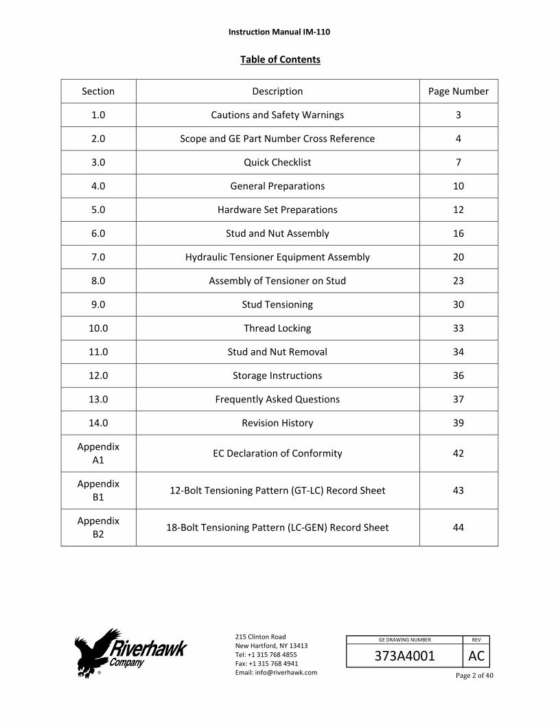
Table of Contents
Section Description Page Number
1.0 Cautions and Safety Warnings 3
2.0 Scope and GE Part Number Cross Reference 4
3.0 Quick Checklist 7
4.0 General Preparations 10
5.0 Hardware Set Preparations 12
6.0 Stud and Nut Assembly 16
7.0 Hydraulic Tensioner Equipment Assembly 20
8.0 Assembly of Tensioner on Stud 23
9.0 Stud Tensioning 30
10.0 Thread Locking 33
11.0 Stud and Nut Removal 34
12.0 Storage Instructions 36
13.0 Frequently Asked Questions 37
14.0 Revision History 39
Appendix A1
EC Declaration of Conformity 42
Appendix B1
12‐Bolt Tensioning Pattern (GT‐LC) Record Sheet 43
Appendix B2
18‐Bolt Tensioning Pattern (LC‐GEN) Record Sheet 44
Instruction Manual IM‐110
215 Clinton Road New Hartford, NY 13413 Tel: +1 315 768 4855 Fax: +1 315 768 4941 Email: [email protected]
AC
REV
373A4001
GE DRAWING NUMBER
Page3of40
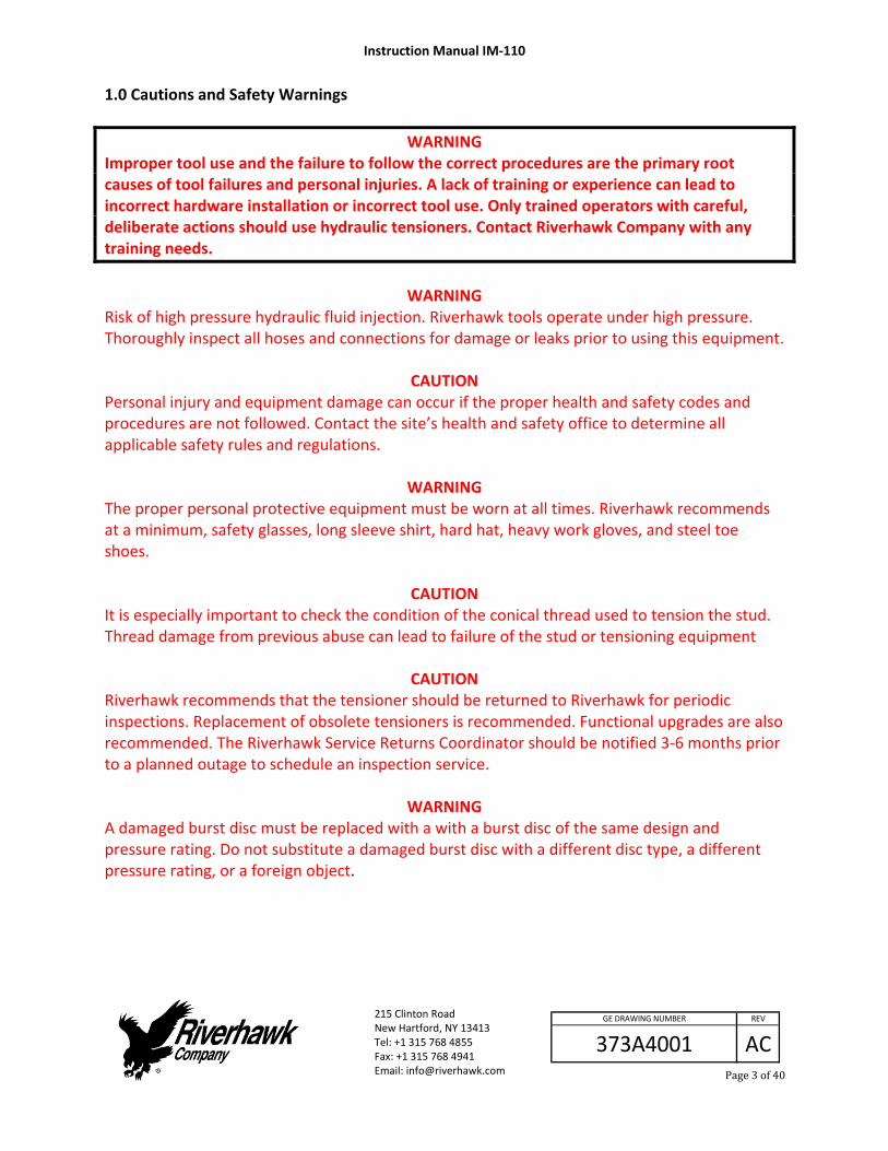
1.0 Cautions and Safety Warnings
WARNING Improper tool use and the failure to follow the correct procedures are the primary root causes of tool failures and personal injuries. A lack of training or experience can lead to incorrect hardware installation or incorrect tool use. Only trained operators with careful, deliberate actions should use hydraulic tensioners. Contact Riverhawk Company with any training needs.
WARNING
Risk of high pressure hydraulic fluid injection. Riverhawk tools operate under high pressure. Thoroughly inspect all hoses and connections for damage or leaks prior to using this equipment.
CAUTION Personal injury and equipment damage can occur if the proper health and safety codes and procedures are not followed. Contact the site’s health and safety office to determine all applicable safety rules and regulations.
WARNING
The proper personal protective equipment must be worn at all times. Riverhawk recommends at a minimum, safety glasses, long sleeve shirt, hard hat, heavy work gloves, and steel toe shoes.
CAUTION It is especially important to check the condition of the conical thread used to tension the stud. Thread damage from previous abuse can lead to failure of the stud or tensioning equipment
CAUTION Riverhawk recommends that the tensioner should be returned to Riverhawk for periodic inspections. Replacement of obsolete tensioners is recommended. Functional upgrades are also recommended. The Riverhawk Service Returns Coordinator should be notified 3‐6 months prior to a planned outage to schedule an inspection service.
WARNING A damaged burst disc must be replaced with a with a burst disc of the same design and pressure rating. Do not substitute a damaged burst disc with a different disc type, a different pressure rating, or a foreign object.

Instruction Manual IM‐110
215 Clinton Road New Hartford, NY 13413 Tel: +1 315 768 4855 Fax: +1 315 768 4941 Email: [email protected]
AC
REV
373A4001
GE DRAWING NUMBER
Page4of40
WARNING To avoid failure, ensure safety, and proper operation, the tensioner assembly must be installed on a stud in the flange before bleeding and pressurizing the tensioner. Do not use the tensioner at any pressure unless the tool is installed on a stud in a flange.
CAUTION Do not over stroke the tensioner. Over stroke can cause the piston to lose its seal and leak oil.
CAUTION Personal injury and equipment damage can occur if the puller screw is not securely engaged with the tapered threads of the stud. Proper engagement is achieved when the puller screw is tight in the stud and the tensioner assembly is free to turn.
WARNING The safety cage must be in place at all times. When the tensioner is pressurized hands must be kept out of designated areas to avoid any potential for personal injury.
CAUTION Before threading the puller screw into the stud, carefully check the cleanliness of both the stud's and the puller screw's conical threads. Apply a light coat of clean turbine oil or a spray lubricant to the puller screw. This procedure will ease assembly and assure positive mating of the threads before tightening. Do not use “Never Seize” on the conical threads.
CAUTION Do not tighten the nut while the tool is coming up to pressure; wait until pressure is achieved before attempting to tighten the nut with the spanner ring. If the tool is not properly installed, the tool could jump off the stud while coming up to pressure.
CAUTION Do not exceed the maximum pressure marked on the tensioner. Excessive pressure can damage the stud and puller screw.
WARNING FIRE HAZARD: DO NOT heat when puller assembly is in place. Personal injury or equipment damage may occur. Use of an Oxy‐Acetylene torch is not recommended 2.0 Scope This document describes the procedure to be used to install the stud and nut sets supplied by the Riverhawk Company in the flanges at the Turbine/Coupling, Coupling/Generator, and Steam Turbine/Generator connections.
Instruction Manual IM‐110
215 Clinton Road New Hartford, NY 13413 Tel: +1 315 768 4855 Fax: +1 315 768 4941 Email: [email protected]
AC
REV
373A4001
GE DRAWING NUMBER
Page5of40
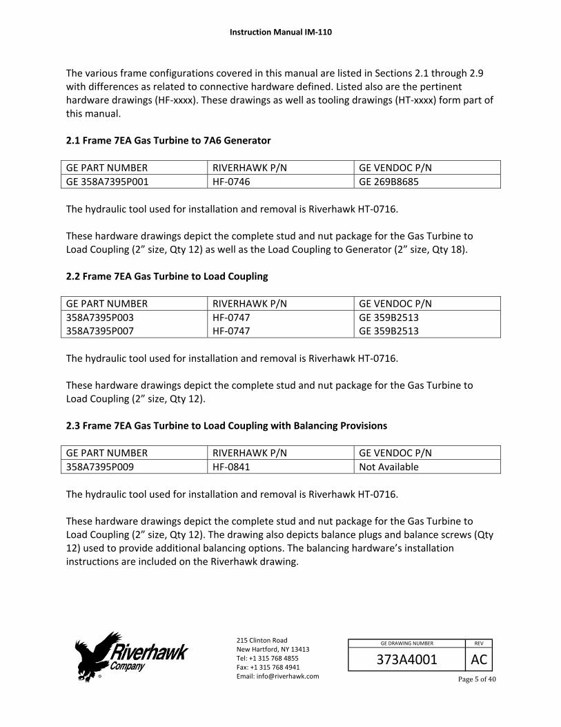
The various frame configurations covered in this manual are listed in Sections 2.1 through 2.9 with differences as related to connective hardware defined. Listed also are the pertinent hardware drawings (HF‐xxxx). These drawings as well as tooling drawings (HT‐xxxx) form part of this manual. 2.1 Frame 7EA Gas Turbine to 7A6 Generator
GE PART NUMBER RIVERHAWK P/N GE VENDOC P/N
GE 358A7395P001 HF‐0746 GE 269B8685
The hydraulic tool used for installation and removal is Riverhawk HT‐0716. These hardware drawings depict the complete stud and nut package for the Gas Turbine to Load Coupling (2” size, Qty 12) as well as the Load Coupling to Generator (2” size, Qty 18). 2.2 Frame 7EA Gas Turbine to Load Coupling
GE PART NUMBER RIVERHAWK P/N GE VENDOC P/N
358A7395P003 358A7395P007
HF‐0747 HF‐0747
GE 359B2513 GE 359B2513
The hydraulic tool used for installation and removal is Riverhawk HT‐0716. These hardware drawings depict the complete stud and nut package for the Gas Turbine to Load Coupling (2” size, Qty 12). 2.3 Frame 7EA Gas Turbine to Load Coupling with Balancing Provisions
GE PART NUMBER RIVERHAWK P/N GE VENDOC P/N
358A7395P009 HF‐0841 Not Available
The hydraulic tool used for installation and removal is Riverhawk HT‐0716. These hardware drawings depict the complete stud and nut package for the Gas Turbine to Load Coupling (2” size, Qty 12). The drawing also depicts balance plugs and balance screws (Qty 12) used to provide additional balancing options. The balancing hardware’s installation instructions are included on the Riverhawk drawing.
Instruction Manual IM‐110
215 Clinton Road New Hartford, NY 13413 Tel: +1 315 768 4855 Fax: +1 315 768 4941 Email: [email protected]
AC
REV
373A4001
GE DRAWING NUMBER
Page6of40
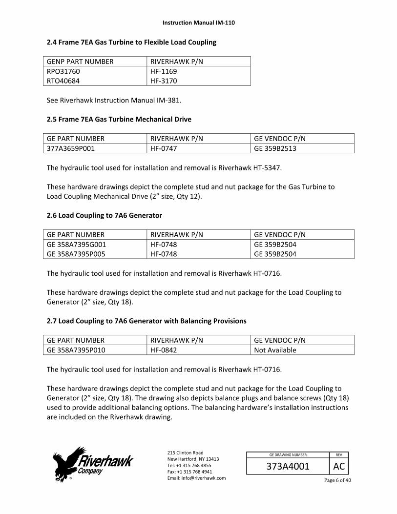
2.4 Frame 7EA Gas Turbine to Flexible Load Coupling
GENP PART NUMBER RIVERHAWK P/N
RPO31760 RTO40684
HF‐1169 HF‐3170
See Riverhawk Instruction Manual IM‐381. 2.5 Frame 7EA Gas Turbine Mechanical Drive
GE PART NUMBER RIVERHAWK P/N GE VENDOC P/N
377A3659P001 HF‐0747 GE 359B2513
The hydraulic tool used for installation and removal is Riverhawk HT‐5347. These hardware drawings depict the complete stud and nut package for the Gas Turbine to Load Coupling Mechanical Drive (2” size, Qty 12). 2.6 Load Coupling to 7A6 Generator
GE PART NUMBER RIVERHAWK P/N GE VENDOC P/N
GE 358A7395G001 GE 358A7395P005
HF‐0748 HF‐0748
GE 359B2504 GE 359B2504
The hydraulic tool used for installation and removal is Riverhawk HT‐0716. These hardware drawings depict the complete stud and nut package for the Load Coupling to Generator (2” size, Qty 18). 2.7 Load Coupling to 7A6 Generator with Balancing Provisions
GE PART NUMBER RIVERHAWK P/N GE VENDOC P/N
GE 358A7395P010 HF‐0842 Not Available
The hydraulic tool used for installation and removal is Riverhawk HT‐0716. These hardware drawings depict the complete stud and nut package for the Load Coupling to Generator (2” size, Qty 18). The drawing also depicts balance plugs and balance screws (Qty 18) used to provide additional balancing options. The balancing hardware’s installation instructions are included on the Riverhawk drawing.

Instruction Manual IM‐110
215 Clinton Road New Hartford, NY 13413 Tel: +1 315 768 4855 Fax: +1 315 768 4941 Email: [email protected]
AC
REV
373A4001
GE DRAWING NUMBER
Page7of40
2.8 Steam Turbine to Generator
GE PART NUMBER RIVERHAWK P/N GE VENDOC P/N
GE 382A6063P001 HF‐0748 GE 359B2504
The hydraulic tool used for installation and removal is Riverhawk HT‐2176.
GE PART NUMBER RIVERHAWK P/N GE VENDOC P/N
GE 387A4804P001 HF‐0748 GE 359B2504
The hydraulic tool used for installation and removal is Riverhawk HT‐0716. These hardware drawings depict the complete stud and nut package for the Steam Turbine to Generator (2” size, Qty 18). 2.9 Hydraulic Tooling
GE PART NUMBER RIVERHAWK P/N GE VENDOC P/N
GE 358A7395P008 HT‐0716 MP‐0130
GE 359B2503 GE 359B2506
GENP PART NUMBER RIVERHAWK P/N
GENP RAO23423 GENP RPO31763
HT‐1168 MTP‐3241‐3 HT‐1168
See Riverhawk Instruction Manual IM‐381
3.0 Quick Checklist The following checklist is intended as a summary of the steps needed to use the Riverhawk‐supplied equipment. New personnel or those experienced personnel who have not used the Riverhawk equipment recently are encouraged to read the entire manual.
EQUIPMENT INSPECTION
□ Check oil level in hydraulic pump.
□ Check air pressure at 80psi [5.5 bar] minimum. (For air‐driven pumps)
□ Check hydraulic hose for damage.
□ Test pump.
Instruction Manual IM‐110
215 Clinton Road New Hartford, NY 13413 Tel: +1 315 768 4855 Fax: +1 315 768 4941 Email: [email protected]
AC
REV
373A4001
GE DRAWING NUMBER
Page8of40
□ Inspect tensioner for any damage.
NUT AND STUD PREPARATION
□ Inspect studs and nuts for any damage.
□ Clean the studs and nuts.
□ Measure stud lengths. (VERY IMPORTANT)
□ Install studs and nuts into the flange.
□ Set stick‐out dimension on the coupling side of the flange.
□ Hand tighten nuts on turbine / generator side of flange.
□ Verify stick‐out measurement (VERY IMPORTANT)
TENSIONING (Bolt Installation)
□ Check tensioner drawing for correct parts and part numbers.
□ Apply a light coat of clean turbine oil or spray lubricant to the puller screw. DO NOT USE “NEVER SEIZE” ON THE CONICAL THREADS.
□ Slide spanner ring over the puller screw.
□ Install the tensioner on the stud in flange and slide spanner ring onto nut.
□ Insert 1/2” hex Allen wrench into the back side of the stud.
□ Tighten the puller screw. Then back off puller screw 1/2 a turn.
□ Retighten the puller screw and leave tight. DO NOT BACK OFF PULLER SCREW.
□ Tighten puller nut and then back nut off two flats or 120 degrees to allow for stud stretch.
Instruction Manual IM‐110
215 Clinton Road New Hartford, NY 13413 Tel: +1 315 768 4855 Fax: +1 315 768 4941 Email: [email protected]
AC
REV
373A4001
GE DRAWING NUMBER
Page9of40
□ Bleed the tensioner. Do NOT bleed tensioner off of a stud! Damage to the tool will result!
□ Tension to 50%. Consult manual for correct pressure.
□ Use the pin wrench in spanner ring to tighten nut.
□ Release pressure, move to next stud in pattern.
□ Repeat above steps at final pressure.
□ Measure final stud length and record on stretch datasheets. Calculate stretch.
□ Torque the nuts' set screws.
DETENSIONING (Stud Removal)
□ Loosen nuts' set screws
□
Inspect and clean studs' conical threads. Do not continue until ALL debris is removed from the threads! See instruction manual IM‐220. Do not try to use the tensioner to remove a damaged stud!
□ Apply a light coat of clean turbine oil or spray lubricant to the puller screw. DO NOT USE “NEVER SEIZE” ON THE CONICAL THREADS.
□ Slide spanner ring over the puller screw.
□ Install the tensioner on the stud.
□ Install spanner ring into nut.
□ Tighten the puller screw. Then back off puller screw 1/2 a turn.
□ Retighten the puller screw and leave tight. DO NOT BACK OFF PULLER SCREW.
□ Tighten puller nut and then back nut off two flats or 120 degrees to allow for stud stretch.
Instruction Manual IM‐110
215 Clinton Road New Hartford, NY 13413 Tel: +1 315 768 4855 Fax: +1 315 768 4941 Email: [email protected]
AC
REV
373A4001
GE DRAWING NUMBER
Page10of40
□ Bleed the tensioner. Do NOT bleed tensioner off of a stud! Damage to the tool will result!
□ Apply final pressure.
□ Loosen nut with the spanner ring and pin wrench.
□ Move to next stud in pattern
4.0 General Preparations Read and understand all instructions before installing and tensioning studs. Operators should be trained or have previous experience using Riverhawk tensioning equipment. Training will minimize the chance of improper use of the equipment. The hydraulic tooling including the hydraulic hoses should be inspected prior to use. Inspection guidelines are listed in the following sub‐sections. This equipment produces very high hydraulic pressures and very high forces. Operators must exercise caution and wear the appropriate personal protective equipment when handling and operating the hydraulic tooling. High‐pressure oil from the hydraulic pump pressurizes the tensioner which generates a very large force that actually stretches the stud. As the stud is stretched the nut lifts off the flange. The nut is then turned by hand using the supplied spanner ring. Once the nut is tight against the flange, the pressure in the tensioner is released. The hardware is now clamping the flange together. 4.1 Machine Preparation The flange to be tensioned must be fully closed prior to positioning the studs in the flanges. There must be provisions for turning the shafts of the turbine, coupling, gearbox, and generator. Also, it will be advantageous to remove as many obstructions as possible from the flange area, such as speed probes and conduit.

Instruction Manual IM‐110
215 Clinton Road New Hartford, NY 13413 Tel: +1 315 768 4855 Fax: +1 315 768 4941 Email: [email protected]
AC
REV
373A4001
GE DRAWING NUMBER
Page11of40
4.2 Hardware – Balance The studs are supplied in component balanced sets. A stud can be exchanged with another in its set without affected the overall balance of the equipment. Do not exchange a stud from one set with another stud from a different set. When shipped from Riverhawk, the studs are not assigned to any specific hole in the load coupling flange; this is optional and can be done at the installation site. The set size is determined by the relevant GE order drawing (see section 2.0).
The nuts are supplied in component balanced sets. A nut can be exchanged with another in its set without affecting the overall balance of the equipment. Do not exchange a nut from one set with another nut from a different set. When shipped from Riverhawk, the nuts are not assigned to any specific hole in the load coupling flange; this is optional and can be done at the installation site. The set size is determined by the relevant GE order drawing (see section 2.0).
A weight balance certification is supplied with each order. Store this certification in an appropriate location as it will be needed for the purchase of replacement equipment. 4.3 Tensioner – Care and Handling When not in use, the tensioner shall be maintained in a clean environment and all caps and plugs for hydraulic openings and fittings must be in place. Use ISO 32 grade oil. When in use, the tensioner shall be protected from sand and grit. See section 12 for long term storage requirements. 4.4 Hand Tools Several hand wrenches and micrometers will be required to perform installation and measurement of the studs: 5/8” wrench A set of Allen Wrenches 3’ – 4’ Breaker Bar 8” to 9” micrometer

Instruction Manual IM‐110
215 Clinton Road New Hartford, NY 13413 Tel: +1 315 768 4855 Fax: +1 315 768 4941 Email: [email protected]
AC
REV
373A4001
GE DRAWING NUMBER
Page12of40
4.5 Riverhawk Tools
Hydraulic Tensioner Kits: Note: Review section 2 to
determine the correct tensioner to use.
HT‐0716 Hydraulic Tensioner, 2” (reference GE VENDOC 359B2503)
HT‐2176 Hydraulic Tensioner, 2”
HT‐5347 Hydraulic Tensioner, 2” (reference GE VENDOC 269B8703)
Obsolete Hydraulic Tensioner Kits: HT‐0252 Hydraulic Tensioner, 2” (OBSOLETE, replaced by HT‐0716)
HT‐0286 Hydraulic Tensioner, 2” (reference GE VENDOC 359B2512) (OBSOLETE, replaced by HT‐5347)
Hydraulic Pump Kit: MP‐0130 Manual Hand‐Operated Hydraulic Pump (reference GE VENDOC 359B2506)
AP‐0532 Air‐Operated Hydraulic Pump (reference GE VENDOC 359B2502)
CAUTION
Riverhawk recommends that the tensioners be returned to Riverhawk for periodic inspections. Replacement of obsolete tensioners is recommended. Functional upgrades are also recommended. The Riverhawk Service Returns Coordinator should be notified 3‐6 months prior to a planned outage to schedule an inspection service. 5.0 Hardware Set Preparations
Instruction Manual IM‐110
215 Clinton Road New Hartford, NY 13413 Tel: +1 315 768 4855 Fax: +1 315 768 4941 Email: [email protected]
AC
REV
373A4001
GE DRAWING NUMBER
Page13of40
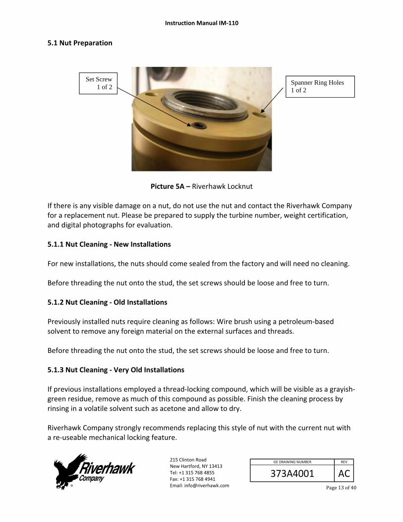
5.1 Nut Preparation
Picture 5A – Riverhawk Locknut If there is any visible damage on a nut, do not use the nut and contact the Riverhawk Company for a replacement nut. Please be prepared to supply the turbine number, weight certification, and digital photographs for evaluation. 5.1.1 Nut Cleaning ‐ New Installations For new installations, the nuts should come sealed from the factory and will need no cleaning. Before threading the nut onto the stud, the set screws should be loose and free to turn. 5.1.2 Nut Cleaning ‐ Old Installations Previously installed nuts require cleaning as follows: Wire brush using a petroleum‐based solvent to remove any foreign material on the external surfaces and threads. Before threading the nut onto the stud, the set screws should be loose and free to turn. 5.1.3 Nut Cleaning ‐ Very Old Installations If previous installations employed a thread‐locking compound, which will be visible as a grayish‐green residue, remove as much of this compound as possible. Finish the cleaning process by rinsing in a volatile solvent such as acetone and allow to dry. Riverhawk Company strongly recommends replacing this style of nut with the current nut with a re‐useable mechanical locking feature.
Set Screw 1 of 2
Spanner Ring Holes 1 of 2

Instruction Manual IM‐110
215 Clinton Road New Hartford, NY 13413 Tel: +1 315 768 4855 Fax: +1 315 768 4941 Email: [email protected]
AC
REV
373A4001
GE DRAWING NUMBER
Page14of40
5.2 Stud Preparation Check the stud for any visible damage. If there is any visible damage, do not use the stud and contact the Riverhawk Company for a replacement stud. Please be prepared to supply the turbine number, weight certification, and digital photographs for evaluation.
CAUTION It is especially important to check the condition of the conical thread used to tension the stud. Thread damage from previous abuse can lead to failure of the stud or tensioning equipment. The conical threads of each stud must be clean of grit and dirt before installation or removal. This ensures the proper seating of the puller screw. 5.2.1 Stud Cleaning ‐ New Installations For new installations, the studs should come sealed from the factory and will need no cleaning. 5.2.2 Stud Cleaning ‐ Old Installations Previously installed studs may require cleaning. Clean conical threads should have a bright and shiny appearance. If cleaning is required, follow these steps:
1. Blow out the threads with compressed air to remove loose debris and dry conical threads. Do not apply a solvent or other cleaning solution to the threads as this may chemically attack the stud.
2. Use Stud Cleaning Kit, GT‐4354 or a similar 1/2" diameter Brass power brush.
Picture 5B ‐ Brass Power Brush
3. Insert the brush into an electric drill and set drill to run in a counterclockwise direction
at high speed.

Instruction Manual IM‐110
215 Clinton Road New Hartford, NY 13413 Tel: +1 315 768 4855 Fax: +1 315 768 4941 Email: [email protected]
AC
REV
373A4001
GE DRAWING NUMBER
Page15of40
4. Work the drill in a circular motion while moving the brush in and out to clean all of the threads. Try not to hold the brush in one place too long, so as not to remove the stud's protective coating.
5. Blow out the threads with compressed air to remove loosened debris.
6. Visually inspect threads for cleanliness. Threads should be bright and shiny.
7. Repeat if any dirt can be seen in the threads.
8. Inspect threads for any damage that may have been caused by previous installation.
9. Do not apply thread lubricants such as “Never Seize” to the stud’s threads.
10. Finish the cleaning process by rinsing in a volatile solvent such as acetone and allow to dry.
5.2.3 Stud Cleaning ‐ Very Old Installations If previous installation employed a thread locking compound, which will be visible as a grayish‐green residue, remove as much of this compound as possible from the stud’s threads. Finish the cleaning process by rinsing in a volatile solvent such as acetone and allow to dry. 5.3 Stud Length Measurement Measure and record the initial lengths of the studs. The following suggestions will improve your results.
Plan to start and finish any flange in the same day.
Studs and flange must be at the same temperature.
Number each stud with a marker for later stretch measurement tracking.
Mark the location of measurement on stud end with a permanent marker.
Measure each stud to nearest 0.001 inch (.01 mm).
Record each measurement on the supplied record sheets.
Do not allow the measuring instruments to sit in the sun.
The same person should make all measurements.

Instruction Manual IM‐110
215 Clinton Road New Hartford, NY 13413 Tel: +1 315 768 4855 Fax: +1 315 768 4941 Email: [email protected]
AC
REV
373A4001
GE DRAWING NUMBER
Page16of40
6.0 Stud and Nut Assembly Refer to the hardware assembly drawing (HF‐xxxx) listed in Section 2.0 of this manual.
1. Assemble the cylindrical nut to the internal, conical thread end of the stud.
2. Slide the stud and cylindrical nut assembly into the flange as shown in Figures 6A, 6B, and 6C.
Figure 6A – Cross‐section View of Gas Turbine to Rigid Load Coupling Bolted Flange Connection
Gas Turbine Flange
Rigid Load Coupling Flange
Nut
Hex Drive
Stud
Tensioning Conical Thread * Set Stud Stick‐out on this side only
Nut

Instruction Manual IM‐110
215 Clinton Road New Hartford, NY 13413 Tel: +1 315 768 4855 Fax: +1 315 768 4941 Email: [email protected]
AC
REV
373A4001
GE DRAWING NUMBER
Page17of40
Figure 6B – Cross‐section View of Rigid Load Coupling or Steam Turbine to Generator Bolted Flange Connection
Figure 6C – Cross‐section View of Gas Turbine to Mechanical Drive Bolted Flange Connection
Rigid Load Coupling or Steam Turbine Flange
Generator Flange
Nut
Hex Drive
Stud
Tensioning Conical Thread
* Set Stud Stick‐out on this side only
Nut
Turbine Flange
Coupling Flange Adapter
Nut
Hex Drive
Stud
Tensioning Conical Thread * Set Stud Stick‐out on this side only
Instruction Manual IM‐110
215 Clinton Road New Hartford, NY 13413 Tel: +1 315 768 4855 Fax: +1 315 768 4941 Email: [email protected]
AC
REV
373A4001
GE DRAWING NUMBER
Page18of40
3. Install the other nut on the backside.
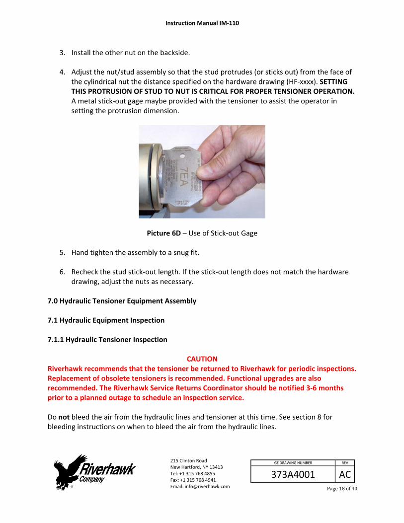
4. Adjust the nut/stud assembly so that the stud protrudes (or sticks out) from the face of
the cylindrical nut the distance specified on the hardware drawing (HF‐xxxx). SETTING THIS PROTRUSION OF STUD TO NUT IS CRITICAL FOR PROPER TENSIONER OPERATION. A metal stick‐out gage maybe provided with the tensioner to assist the operator in setting the protrusion dimension.
Picture 6D – Use of Stick‐out Gage
5. Hand tighten the assembly to a snug fit.
6. Recheck the stud stick‐out length. If the stick‐out length does not match the hardware drawing, adjust the nuts as necessary.
7.0 Hydraulic Tensioner Equipment Assembly 7.1 Hydraulic Equipment Inspection 7.1.1 Hydraulic Tensioner Inspection
CAUTION Riverhawk recommends that the tensioner be returned to Riverhawk for periodic inspections. Replacement of obsolete tensioners is recommended. Functional upgrades are also recommended. The Riverhawk Service Returns Coordinator should be notified 3‐6 months prior to a planned outage to schedule an inspection service. Do not bleed the air from the hydraulic lines and tensioner at this time. See section 8 for bleeding instructions on when to bleed the air from the hydraulic lines.

Instruction Manual IM‐110
215 Clinton Road New Hartford, NY 13413 Tel: +1 315 768 4855 Fax: +1 315 768 4941 Email: [email protected]
AC
REV
373A4001
GE DRAWING NUMBER
Page19of40
WARNING To avoid failure, ensure safety, and proper operation, the tensioner assembly must be installed on a stud in the flange before bleeding and pressurizing the tensioner. Do not use the tensioner at any pressure unless the tool is installed on a stud in a flange. Check puller screw usage life with Riverhawk service bulletin SB‐08001. Clean puller screw and check for any debris and dents. Puller screw should be free to rotate and move back and forth. Seam between cylinders closed tightly. Inspect the tensioner guard for any signs of damage including cracked welds. Any guards modified in the field should be replaced. Bent guards should be replaced. Inspect the outside of the tensioner for discoloration patterns that may indicate submersion and internal damage. Perform an inventory of the loose equipment supplied with the tensioner. An inventory list is provided on the tensioner’s technical drawing (for example Riverhawk HT‐xxxx). Replacement parts are available from Riverhawk. 7.1.1.1 Hydraulic Tensioner’s Burst Disc Replacement The hydraulic tensioner’s burst disc is a key element in the overall safe use of the hydraulic tensioner. Each tensioner is shipped from our factory with one burst disc already installed in the tensioner and with another spare disc for field replacement. Extra burst discs are available from Riverhawk for replacement purposes. To replace a damaged burst disc:
1. Remove the hydraulic port’s dispersion nut, compression ring, and damaged burst disc. 2. Discard the damaged burst disc. 3. Clean the dispersion nut, compression ring, new burst disc, and the hydraulic port with a
solvent to ensure a dirt‐free installation. 4. Reassemble new burst disc, compression ring, and dispersion nut into the same
hydraulic port.

Instruction Manual IM‐110
215 Clinton Road New Hartford, NY 13413 Tel: +1 315 768 4855 Fax: +1 315 768 4941 Email: [email protected]
AC
REV
373A4001
GE DRAWING NUMBER
Page20of40
Warning A damaged burst disc must be replaced with a with a burst disc of the same design and pressure rating. Do not substitute a damaged burst disc with a different disc type, a different pressure rating, or a foreign object. 7.1.2 Hydraulic Pump Kit Inspection Refer to the Hydraulic Pump Kit Instruction Manual, IM‐293 (GE VENDOC 373A4058). The latest revision may be obtained by contacting Riverhawk Company or thru www.riverhawk.com. 7.2 Hydraulic Fittings
Illustration 1
Riverhawk tensioners use a 1/4” High Pressure port to connect its hydraulic hoses. The hose connector is made from a three piece assembly: a gland nut, a collar, and a 1/4” tube or 1/4” hose end. (See Illustration 1) To assembly the fitting, slide the gland nut over the 1/4” tube or 1/4” hose end. Turn the collar counter‐clockwise (left hand thread) on to the tube or hose end as shown in Illustration 1.
Illustration 2
The collar should be placed .125” (3.2 mm) from the tip of the cone. (See Illustration 2) It may be necessary to adjust this collar with a set of vise‐grip pliers. Be careful to not strip the threads off the tube or hose end.

Instruction Manual IM‐110
215 Clinton Road New Hartford, NY 13413 Tel: +1 315 768 4855 Fax: +1 315 768 4941 Email: [email protected]
AC
REV
373A4001
GE DRAWING NUMBER
Page21of40
Illustration 3
Slide the gland nut down over the collar. (See Illustration 3) Insert the 1/4” tube or 1/4” hose end into tensioner or hydraulic pump. While firmly holding the tube or hose end to stop it from rotating, turn the gland nut clockwise (right hand thread) and torque the gland nut to 25 FT‐LBS (34 N‐m). Tips: Make sure all parts are clean and free from
debris. Protect the cone on the end of the 1/4” tube
or 1/4” hose end from scratches as this is the sealing surface.
Replace red plastic caps when finished to protect the threads and cone.
8.0 Assembly of Tensioner on Stud The tensioner used in this application can be identified by its YELLOW safety guard. If the tensioner’s safety guard is ORANGE, a different set of instructions are required. Consult the Riverhawk factory for assistance. 8.1 Handling of the Tensioner The tensioner used in this application is designed to require no special lifting instructions. Do not drop any part of the tensioner on the operator or other nearby personnel. 8.2 Tensioner Kit Assembly This assembly has the following features which should make stud tensioning safer and easier.
The safety cage is integral (bolted) to the tensioner
The hydraulic piston is spring loaded to retract
The puller screw is a 2‐piece design. This requires that the operator tighten the puller screw into the stud and then install a puller nut.

Instruction Manual IM‐110
215 Clinton Road New Hartford, NY 13413 Tel: +1 315 768 4855 Fax: +1 315 768 4941 Email: [email protected]
AC
REV
373A4001
GE DRAWING NUMBER
Page22of40
Figure 8A – Cross‐section View of HT‐0716 on 7EA Gas Turbine Load Coupling Flange
Hex Drive
Gas Turbine Or Generator Flange Load Coupling
Flange
Spanner Ring
Hydraulic Burst Disc Port
Puller Nut
Safety Cage
Nut Stud Nut Cylinder
Piston
Puller Screw
Pin Wrench
Instruction Manual IM‐110
215 Clinton Road New Hartford, NY 13413 Tel: +1 315 768 4855 Fax: +1 315 768 4941 Email: [email protected]
AC
REV
373A4001
GE DRAWING NUMBER
Page23of40
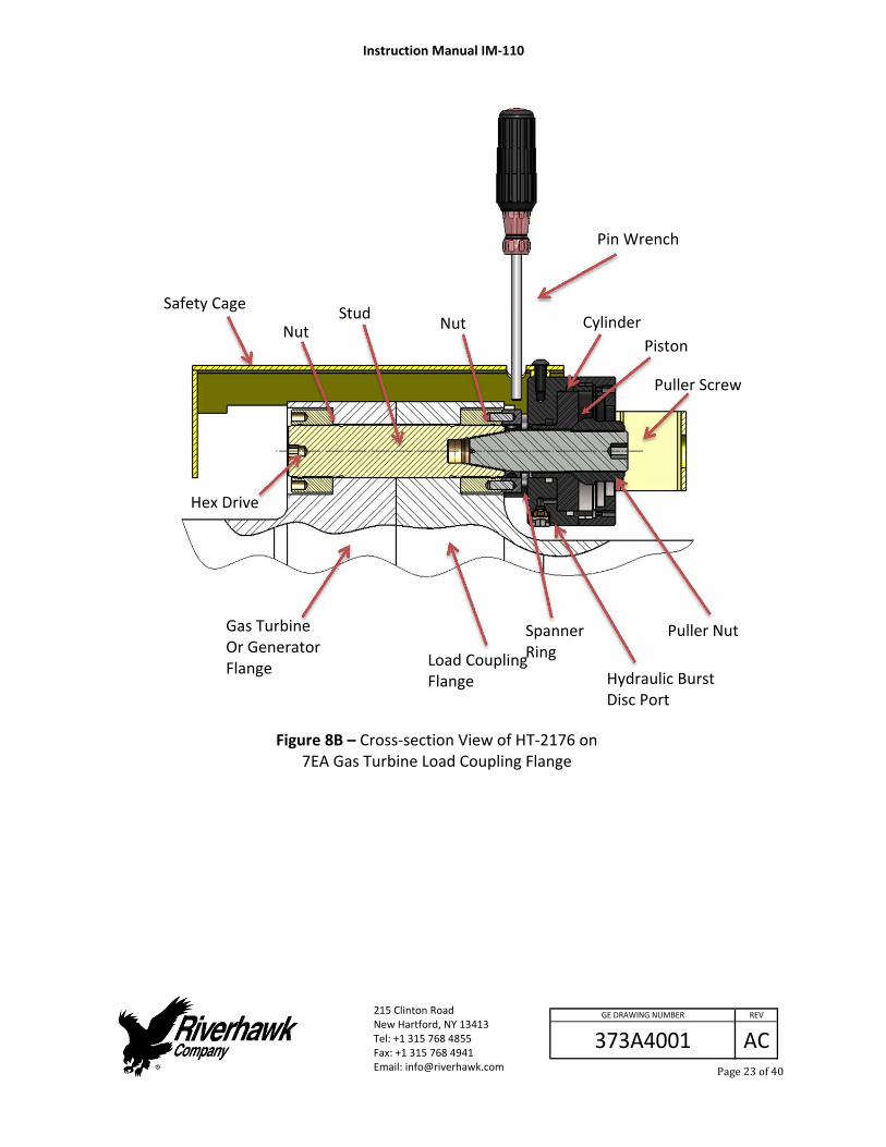
Figure 8B – Cross‐section View of HT‐2176 on 7EA Gas Turbine Load Coupling Flange
Hex Drive
Gas Turbine Or Generator Flange Load Coupling
Flange
Spanner Ring
Hydraulic Burst Disc Port
Puller Nut
Safety Cage
Nut Stud
Nut Cylinder
Piston
Puller Screw
Pin Wrench
Instruction Manual IM‐110
215 Clinton Road New Hartford, NY 13413 Tel: +1 315 768 4855 Fax: +1 315 768 4941 Email: [email protected]
AC
REV
373A4001
GE DRAWING NUMBER
Page24of40
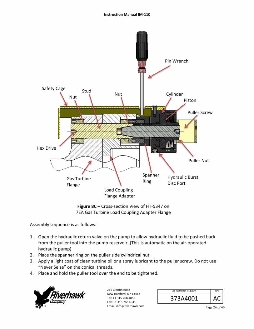
Figure 8C – Cross‐section View of HT‐5347 on 7EA Gas Turbine Load Coupling Adapter Flange
Assembly sequence is as follows: 1. Open the hydraulic return valve on the pump to allow hydraulic fluid to be pushed back
from the puller tool into the pump reservoir. (This is automatic on the air‐operated hydraulic pump)
2. Place the spanner ring on the puller side cylindrical nut. 3. Apply a light coat of clean turbine oil or a spray lubricant to the puller screw. Do not use
“Never Seize” on the conical threads. 4. Place and hold the puller tool over the end to be tightened.
Hex Drive
Gas Turbine Flange
Load Coupling Flange Adapter
Spanner Ring
Hydraulic Burst Disc Port
Puller Nut
Safety Cage
Nut Stud
Nut Cylinder Piston
Puller Screw
Pin Wrench
Instruction Manual IM‐110
215 Clinton Road New Hartford, NY 13413 Tel: +1 315 768 4855 Fax: +1 315 768 4941 Email: [email protected]
AC
REV
373A4001
GE DRAWING NUMBER
Page25of40
5. Insert the puller screw through the tensioner into the tapered thread of the stud and tighten.
6. Be sure not to cross‐thread the assembly. 7. Tighten the puller screw using Allen wrenches on the puller screw and the stud. DO NOT
wrench on the Hex nut opposite the tensioner. 8. Install the puller nut until it seats snugly on the piston and then back‐off 2 flats. This is
particularly important for removal because the stud shortens during disassembly and the tensioner may then bind.
9. At this point the Tensioner Assembly MUST BE FREE TO ROTATE, the puller screw is tight in the stud and the puller nut has been backed‐off the 2 flats.
Note: If the tool is not free to rotate it is most likely that the nuts must be repositioned so that the stud may be shifted slightly to the puller tool side of the flange. This can be accomplished as follows: 1. Back off the puller nut and slightly loosen the puller screw. 2. Back off the Hex nut opposite the puller tool about 1 /2 turn. 3. Tighten the puller screw side cylindrical nut to take up the slack. 4. Retighten the puller screw per above and check for tool looseness.
CAUTION Do not over extend the stud. Over extension can cause the piston to lose its seal and leak oil.
CAUTION Personal injury and equipment damage can occur if the puller screw is not securely engaged with the tapered threads of the stud. Proper engagement is achieved when the puller screw is tight in the stud and the tensioner assembly is free to turn. 8.3 Bleeding the Hydraulic System
WARNING To avoid failure, ensure safety, and proper operation, the tensioner assembly must be installed on a stud in the flange before bleeding and pressurizing the tensioner. Do not use the tensioner at any pressure unless the tool is installed on a stud in a flange.
Instruction Manual IM‐110
215 Clinton Road New Hartford, NY 13413 Tel: +1 315 768 4855 Fax: +1 315 768 4941 Email: [email protected]
AC
REV
373A4001
GE DRAWING NUMBER
Page26of40
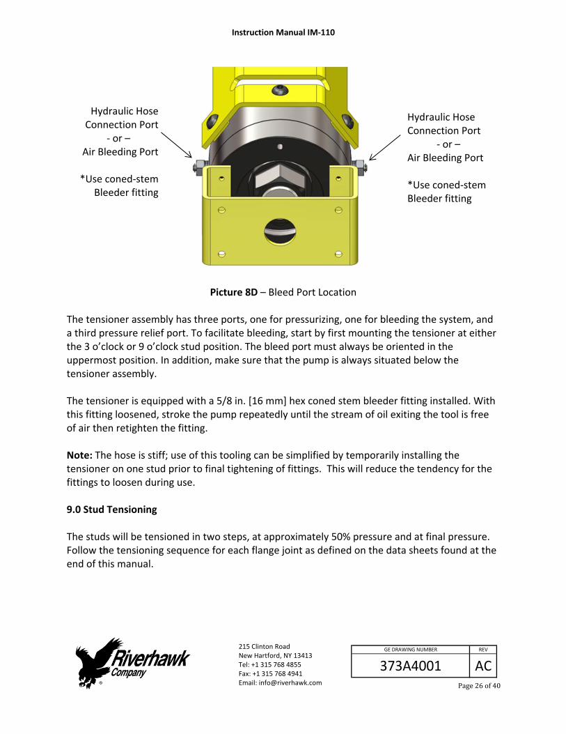
Picture 8D – Bleed Port Location
The tensioner assembly has three ports, one for pressurizing, one for bleeding the system, and a third pressure relief port. To facilitate bleeding, start by first mounting the tensioner at either the 3 o’clock or 9 o’clock stud position. The bleed port must always be oriented in the uppermost position. In addition, make sure that the pump is always situated below the tensioner assembly. The tensioner is equipped with a 5/8 in. [16 mm] hex coned stem bleeder fitting installed. With this fitting loosened, stroke the pump repeatedly until the stream of oil exiting the tool is free of air then retighten the fitting. Note: The hose is stiff; use of this tooling can be simplified by temporarily installing the tensioner on one stud prior to final tightening of fittings. This will reduce the tendency for the fittings to loosen during use. 9.0 Stud Tensioning The studs will be tensioned in two steps, at approximately 50% pressure and at final pressure. Follow the tensioning sequence for each flange joint as defined on the data sheets found at the end of this manual.
Hydraulic Hose Connection Port
‐ or – Air Bleeding Port *Use coned‐stem Bleeder fitting
Hydraulic Hose Connection Port
‐ or – Air Bleeding Port
*Use coned‐stem
Bleeder fitting
Instruction Manual IM‐110
215 Clinton Road New Hartford, NY 13413 Tel: +1 315 768 4855 Fax: +1 315 768 4941 Email: [email protected]
AC
REV
373A4001
GE DRAWING NUMBER
Page27of40
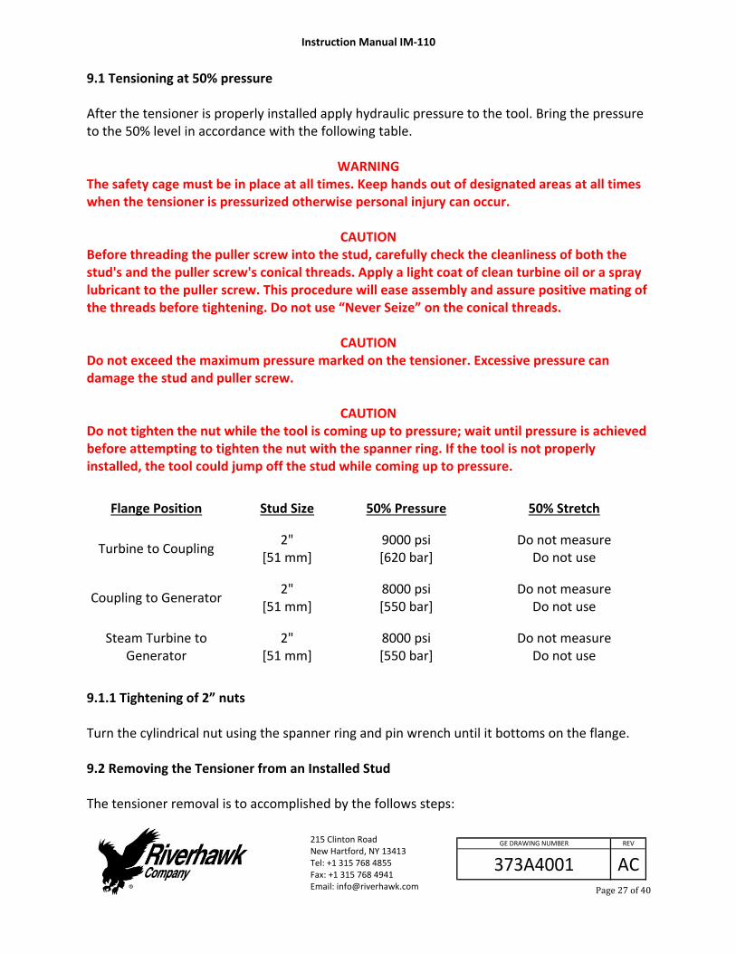
9.1 Tensioning at 50% pressure After the tensioner is properly installed apply hydraulic pressure to the tool. Bring the pressure to the 50% level in accordance with the following table.
WARNING The safety cage must be in place at all times. Keep hands out of designated areas at all times when the tensioner is pressurized otherwise personal injury can occur.
CAUTION Before threading the puller screw into the stud, carefully check the cleanliness of both the stud's and the puller screw's conical threads. Apply a light coat of clean turbine oil or a spray lubricant to the puller screw. This procedure will ease assembly and assure positive mating of the threads before tightening. Do not use “Never Seize” on the conical threads.
CAUTION Do not exceed the maximum pressure marked on the tensioner. Excessive pressure can damage the stud and puller screw.
CAUTION Do not tighten the nut while the tool is coming up to pressure; wait until pressure is achieved before attempting to tighten the nut with the spanner ring. If the tool is not properly installed, the tool could jump off the stud while coming up to pressure.
Flange Position Stud Size 50% Pressure 50% Stretch
Turbine to Coupling 2"
[51 mm] 9000 psi [620 bar]
Do not measure Do not use
Coupling to Generator 2"
[51 mm] 8000 psi [550 bar]
Do not measure Do not use
Steam Turbine to Generator
2" [51 mm]
8000 psi [550 bar]
Do not measure Do not use
9.1.1 Tightening of 2” nuts Turn the cylindrical nut using the spanner ring and pin wrench until it bottoms on the flange. 9.2 Removing the Tensioner from an Installed Stud The tensioner removal is to accomplished by the follows steps:
Instruction Manual IM‐110
215 Clinton Road New Hartford, NY 13413 Tel: +1 315 768 4855 Fax: +1 315 768 4941 Email: [email protected]
AC
REV
373A4001
GE DRAWING NUMBER
Page28of40
1. Release the puller tool pressure by opening the valve on the pump. Leave valve open. (This is automatic on the air‐operated hydraulic pump)
2. Unscrew the puller screw using a wrench. 3. Tapping the allen wrench with a hammer may be necessary to loosen the puller screw 4. Move the tool to the next stud/nut assembly to be tensioned, following the
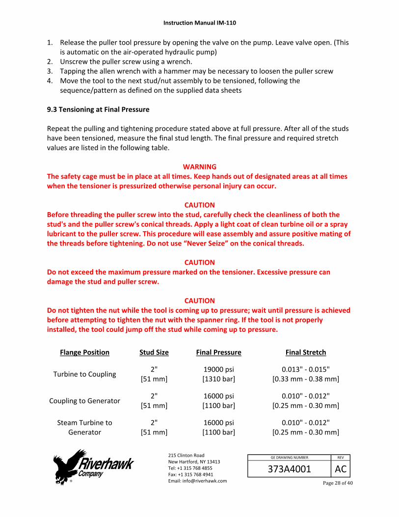
sequence/pattern as defined on the supplied data sheets 9.3 Tensioning at Final Pressure Repeat the pulling and tightening procedure stated above at full pressure. After all of the studs have been tensioned, measure the final stud length. The final pressure and required stretch values are listed in the following table.
WARNING The safety cage must be in place at all times. Keep hands out of designated areas at all times when the tensioner is pressurized otherwise personal injury can occur.
CAUTION Before threading the puller screw into the stud, carefully check the cleanliness of both the stud's and the puller screw's conical threads. Apply a light coat of clean turbine oil or a spray lubricant to the puller screw. This procedure will ease assembly and assure positive mating of the threads before tightening. Do not use “Never Seize” on the conical threads.
CAUTION Do not exceed the maximum pressure marked on the tensioner. Excessive pressure can damage the stud and puller screw.
CAUTION Do not tighten the nut while the tool is coming up to pressure; wait until pressure is achieved before attempting to tighten the nut with the spanner ring. If the tool is not properly installed, the tool could jump off the stud while coming up to pressure.
Flange Position Stud Size Final Pressure Final Stretch
Turbine to Coupling 2"
[51 mm] 19000 psi [1310 bar]
0.013" ‐ 0.015" [0.33 mm ‐ 0.38 mm]
Coupling to Generator 2"
[51 mm] 16000 psi [1100 bar]
0.010" ‐ 0.012" [0.25 mm ‐ 0.30 mm]
Steam Turbine to Generator
2" [51 mm]
16000 psi [1100 bar]
0.010" ‐ 0.012" [0.25 mm ‐ 0.30 mm]
Instruction Manual IM‐110
215 Clinton Road New Hartford, NY 13413 Tel: +1 315 768 4855 Fax: +1 315 768 4941 Email: [email protected]
AC
REV
373A4001
GE DRAWING NUMBER
Page29of40
Excessive stretch variations or low stretch values can be corrected by uninstalling all or selected studs to the pressure values stated in the above table. Have final stretch values approved by the supervisor responsible for the installation. 9.3.1 Tightening of 2” nuts Turn the cylindrical nut using the spanner ring and pin wrench until it bottoms on the flange. Then apply torque to turn the nut an additional 10 degrees. This will aid in achieving the desired stretch. 10.0 Thread Locking Once pulling and tensioning is completed all stud nuts must be locked in position. Two methods of thread locking may be encountered in the field. Early version hardware required a liquid thread locking compound while the later configuration employs a mechanical locking device. Each method is described in detail in Sections 10.1 & 10.2. 10.1 Thread Locking Using a Liquid Locking Compound These nuts have no visible locking feature. Contact Riverhawk Company if you have any of these older style nuts. Riverhawk Company strongly recommends replacing this style of nut with the current nut with a re‐useable mechanical locking feature.

Instruction Manual IM‐110
215 Clinton Road New Hartford, NY 13413 Tel: +1 315 768 4855 Fax: +1 315 768 4941 Email: [email protected]
AC
REV
373A4001
GE DRAWING NUMBER
Page30of40
10.2 Thread Locking Using a Mechanical Locking Device
Picture 10A ‐ Riverhawk Locknut
Mechanical lock nuts have two set screws located in the top face, see picture. Before threading the nut onto the stud check to be certain the set screws are free to turn. Once the nut is seated torque the set screws to the values specified in the following table. When seated and torqued to the values specified the load created by the set screw displaces the thread of the nut in the area of the web creating the desired locking action.
Stud Size Set Screw Size Torque
2" [51 mm]
1/4"‐28 UN 65 in∙lbs ‐ 75 in∙lbs [7.3 N∙m – 8.3 N∙m]
11.0 Stud and Nut Removal Sections 11.1 and 11.2 respectively describe the procedures to be followed in removing nuts that have been locked with liquid locking compound and those with the mechanical locking feature. 11.1 Removal of Assemblies with Liquid Locking Compound For those assemblies which have been locked with the liquid locking compound, removal is accomplished as follows: Using a wire brush and shop air clean the internal tapered thread of the stud to remove any
debris/deposits that may have accumulated during service. (See section 5.2.2)
Set Screws 1 of 2 Spanner Ring
Holes 1 of 2
Instruction Manual IM‐110
215 Clinton Road New Hartford, NY 13413 Tel: +1 315 768 4855 Fax: +1 315 768 4941 Email: [email protected]
AC
REV
373A4001
GE DRAWING NUMBER
Page31of40
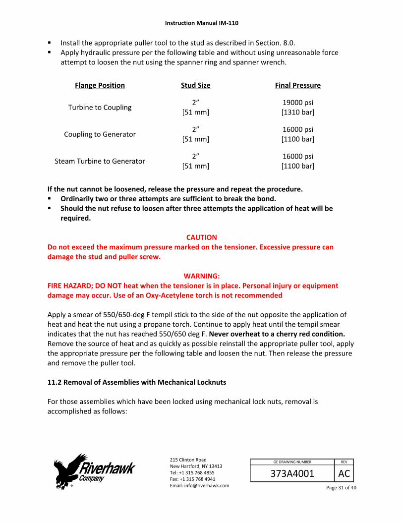
Install the appropriate puller tool to the stud as described in Section. 8.0. Apply hydraulic pressure per the following table and without using unreasonable force
attempt to loosen the nut using the spanner ring and spanner wrench.
Flange Position Stud Size Final Pressure
Turbine to Coupling 2”
[51 mm] 19000 psi [1310 bar]
Coupling to Generator 2”
[51 mm] 16000 psi [1100 bar]
Steam Turbine to Generator 2”
[51 mm] 16000 psi [1100 bar]
If the nut cannot be loosened, release the pressure and repeat the procedure. Ordinarily two or three attempts are sufficient to break the bond. Should the nut refuse to loosen after three attempts the application of heat will be
required.
CAUTION Do not exceed the maximum pressure marked on the tensioner. Excessive pressure can damage the stud and puller screw.
WARNING: FIRE HAZARD; DO NOT heat when the tensioner is in place. Personal injury or equipment damage may occur. Use of an Oxy‐Acetylene torch is not recommended Apply a smear of 550/650‐deg F tempil stick to the side of the nut opposite the application of heat and heat the nut using a propane torch. Continue to apply heat until the tempil smear indicates that the nut has reached 550/650 deg F. Never overheat to a cherry red condition. Remove the source of heat and as quickly as possible reinstall the appropriate puller tool, apply the appropriate pressure per the following table and loosen the nut. Then release the pressure and remove the puller tool. 11.2 Removal of Assemblies with Mechanical Locknuts For those assemblies which have been locked using mechanical lock nuts, removal is accomplished as follows:

Instruction Manual IM‐110
215 Clinton Road New Hartford, NY 13413 Tel: +1 315 768 4855 Fax: +1 315 768 4941 Email: [email protected]
AC
REV
373A4001
GE DRAWING NUMBER
Page32of40
1. Using a wire brush, GT‐4354, and shop air clean the internal tapered thread of the stud to remove any debris/deposits which may have accumulated during service. (see section 5.2.2) With an Allen‐wrench loosen the two locking set screws but do not remove from nut.
Picture 11A ‐ Loosening of a nut's set screws
2. Install the appropriate puller tool to the stud as described in Section 8.0.
3. Apply the appropriate hydraulic pressure per the table of Section 11.1 and using the spanner ring and spanner wrenches loosen the nut, then release the pressure and remove the puller tool.
12.0 Storage Instructions Follow these directions to properly store your hydraulic tensioner and hydraulic pump kit for long term storage and shipment. If any damage is observed, contact the Riverhawk Company to schedule a maintenance inspection. 12.1 Hydraulic Pump Kit Storage Refer to the Hydraulic Pump Kit Instruction Manual, IM‐293 (GE VENDOC 373A4058). The latest revision may be obtained by contacting Riverhawk Company or thru www.riverhawk.com. 12.2 Hydraulic Tensioner Storage Check the tensioner for any damage.
1. Clean puller screw and check for any debris and dents.

Instruction Manual IM‐110
215 Clinton Road New Hartford, NY 13413 Tel: +1 315 768 4855 Fax: +1 315 768 4941 Email: [email protected]
AC
REV
373A4001
GE DRAWING NUMBER
Page33of40
2. Puller screw should be free to rotate and move back and forth. 3. Seam between the cylinder and its end cap is closed tightly. 4. Inspect tensioner guard for any signs of damage. Bent guards should be replaced.
Missing rubber pads must be replaced. If any damage is observed, contact the Riverhawk Company to schedule a maintenance inspection. Place protective red plastic cap into the hydraulic port. Coat the hydraulic tensioner with a light coat of oil and place the tensioner into the original shipping container. 12.3 Store shipping container Secure the hydraulic pump and hydraulic tensioner into the original shipping containers using the supplied wood braces. Seal the original shipping container and store under shelter and protected from moisture, sand, and grit. 13.0 Frequently Asked Questions This section contains some frequently asked questions and problems. If the steps listed here do not solve your problem, contact the Riverhawk Company thru our website, email, or phone call. Q: A:
Can I rent a hydraulic tensioner kit? Yes, Riverhawk has rental tensioner kits available for most of our hydraulic tensioners.
Q: A:
A tensioner has pulled itself out of the stud's conical threads. Can I continue using a tensioner on this stud? No. Both the tensioner and the stud may have been damaged and must be removed from the work area. If the stud is tensioned, a Nut Buster repair kit, from Riverhawk, must be used to remove the damaged stud by drilling out the nut. Leaving a damaged stud in place will lead to a safety hazard on future outages.
Riverhawk can supply a replacement stud and nut based on the initial weight certification supplied with the hardware set (see section 4.2). The damaged tensioner should also be returned to Riverhawk for inspection and repair.
Instruction Manual IM‐110
215 Clinton Road New Hartford, NY 13413 Tel: +1 315 768 4855 Fax: +1 315 768 4941 Email: [email protected]
AC
REV
373A4001
GE DRAWING NUMBER
Page34of40
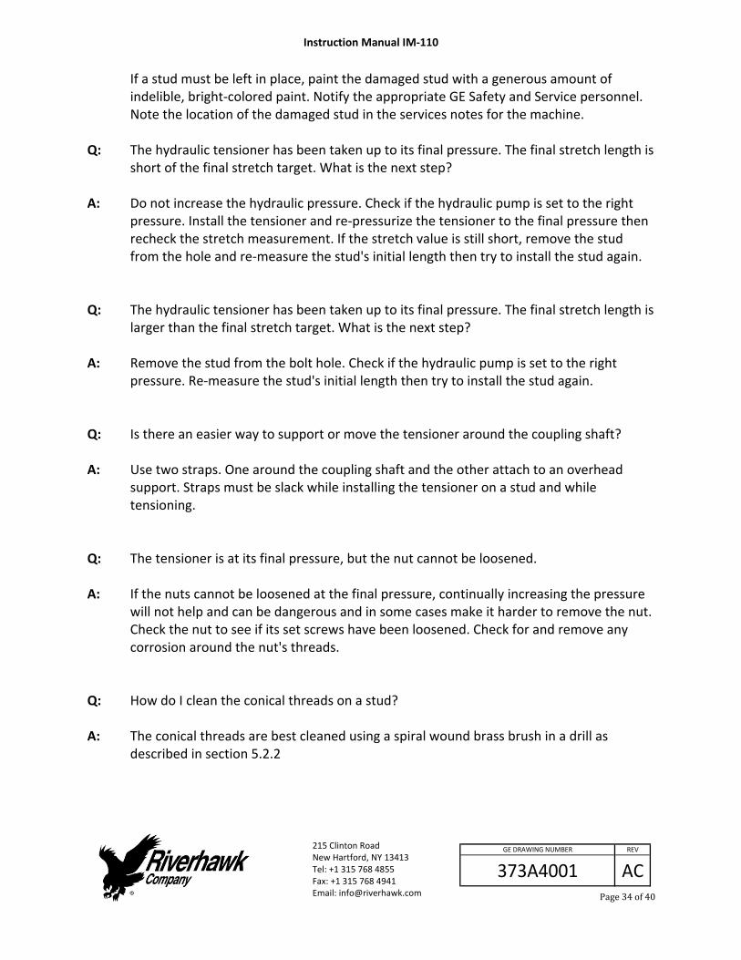
If a stud must be left in place, paint the damaged stud with a generous amount of indelible, bright‐colored paint. Notify the appropriate GE Safety and Service personnel. Note the location of the damaged stud in the services notes for the machine.
Q: A:
The hydraulic tensioner has been taken up to its final pressure. The final stretch length is short of the final stretch target. What is the next step? Do not increase the hydraulic pressure. Check if the hydraulic pump is set to the right pressure. Install the tensioner and re‐pressurize the tensioner to the final pressure then recheck the stretch measurement. If the stretch value is still short, remove the stud from the hole and re‐measure the stud's initial length then try to install the stud again.
Q: A:
The hydraulic tensioner has been taken up to its final pressure. The final stretch length is larger than the final stretch target. What is the next step? Remove the stud from the bolt hole. Check if the hydraulic pump is set to the right pressure. Re‐measure the stud's initial length then try to install the stud again.
Q: A:
Is there an easier way to support or move the tensioner around the coupling shaft? Use two straps. One around the coupling shaft and the other attach to an overhead support. Straps must be slack while installing the tensioner on a stud and while tensioning.
Q: A:
The tensioner is at its final pressure, but the nut cannot be loosened. If the nuts cannot be loosened at the final pressure, continually increasing the pressure will not help and can be dangerous and in some cases make it harder to remove the nut. Check the nut to see if its set screws have been loosened. Check for and remove any corrosion around the nut's threads.
Q: A:
How do I clean the conical threads on a stud? The conical threads are best cleaned using a spiral wound brass brush in a drill as described in section 5.2.2
Instruction Manual IM‐110
215 Clinton Road New Hartford, NY 13413 Tel: +1 315 768 4855 Fax: +1 315 768 4941 Email: [email protected]
AC
REV
373A4001
GE DRAWING NUMBER
Page35of40
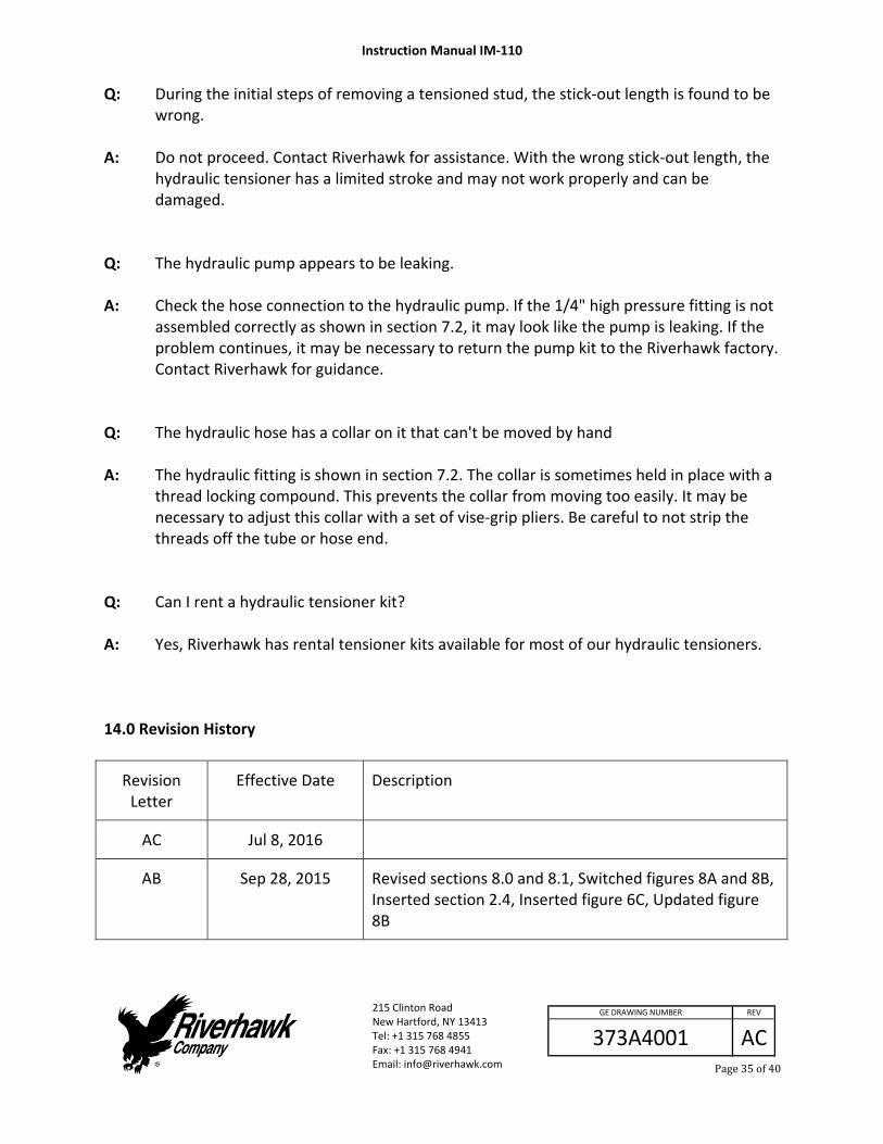
Q: A:
During the initial steps of removing a tensioned stud, the stick‐out length is found to be wrong. Do not proceed. Contact Riverhawk for assistance. With the wrong stick‐out length, the hydraulic tensioner has a limited stroke and may not work properly and can be damaged.
Q: A:
The hydraulic pump appears to be leaking. Check the hose connection to the hydraulic pump. If the 1/4" high pressure fitting is not assembled correctly as shown in section 7.2, it may look like the pump is leaking. If the problem continues, it may be necessary to return the pump kit to the Riverhawk factory. Contact Riverhawk for guidance.
Q: A:
The hydraulic hose has a collar on it that can't be moved by hand The hydraulic fitting is shown in section 7.2. The collar is sometimes held in place with a thread locking compound. This prevents the collar from moving too easily. It may be necessary to adjust this collar with a set of vise‐grip pliers. Be careful to not strip the threads off the tube or hose end.
Q: A:
Can I rent a hydraulic tensioner kit? Yes, Riverhawk has rental tensioner kits available for most of our hydraulic tensioners.
14.0 Revision History
Revision Letter
Effective Date Description
AC Jul 8, 2016
AB Sep 28, 2015 Revised sections 8.0 and 8.1, Switched figures 8A and 8B, Inserted section 2.4, Inserted figure 6C, Updated figure 8B

Instruction Manual IM‐110
215 Clinton Road New Hartford, NY 13413 Tel: +1 315 768 4855 Fax: +1 315 768 4941 Email: [email protected]
AC
REV
373A4001
GE DRAWING NUMBER
Page36of40
Revision Letter
Effective Date Description
AA May 28, 2015 Updated section 4.2, Added RPO31763, renumbered appendices
Z Jan 16, 2015 Updated sections 1.0, 4.3 and Appendix A3.
Y Jun 13, 2014 Added EC Declaration of Conformity
W Nov 6, 2012 Reformatted, general update to warnings and cautions, Added IM‐293 to sections 7.1.2 and 12.1
V Feb 27, 2012 Updated stretch records sheets on pages 39 and 40
U Oct 19, 2011 Added HT‐5347 Hydraulic Tensioner to section 4.5, Revised Figures 1 thru 5, Removed figures 6 thru 9
T Jun 24, 2010 Revised section 12.2: Figure 4 on page 33, referenced section 8.0 was 9.3, referenced section 9.3 was 10.1, figures 5,6,7 on page 34‐35
S Mar 26, 2010 Revised metric conversion of hydraulic pressure in Section 9.3
R Aug 18, 2009 Added section 13, revised section 5.1, 5.2, 7.1.1, 9.1, 9.3, and 11.1
Q Jun 10, 2009 Added turbine oil and removed “Never Seize” from sections 1.0, 3.0, 8.1, 8.2, and 9.0
P Mar 25, 2009 Added sections 3.0 and 13.0
N Apr 07, 2008 Added dual units [metric]
M Jun 22, 2005 Added HT‐1168, updated additional information
L Jun 01, 2005 Added HT‐2176, updated additional information
K Jan 13, 2005 Moved caution notes
J Oct 24, 2002 GE Dwg Rev. ltr A, Page 9 para 10.1
H Oct 02, 2001 Added GE title block to all pages
Instruction Manual IM‐110
215 Clinton Road New Hartford, NY 13413 Tel: +1 315 768 4855 Fax: +1 315 768 4941 Email: [email protected]
AC
REV
373A4001
GE DRAWING NUMBER
Page37of40
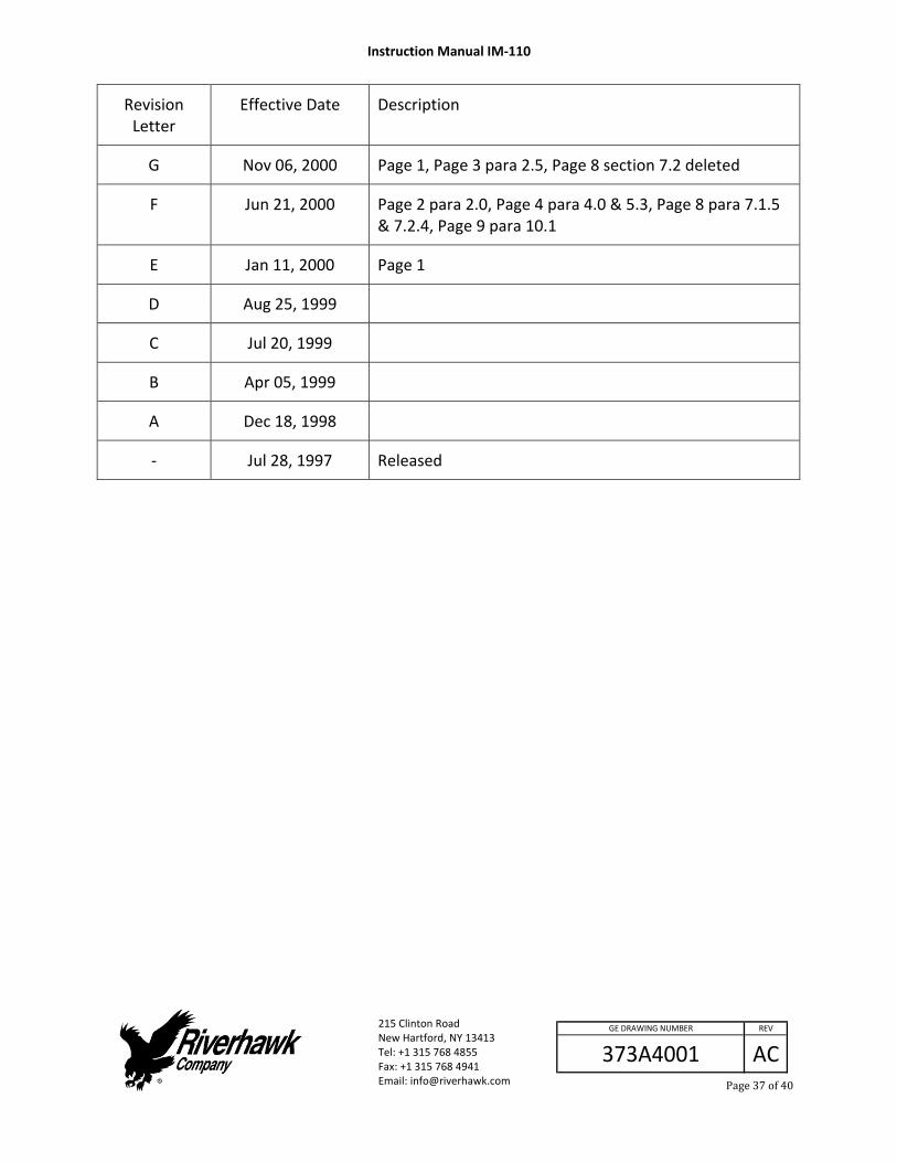
Revision Letter
Effective Date Description
G Nov 06, 2000 Page 1, Page 3 para 2.5, Page 8 section 7.2 deleted
F Jun 21, 2000 Page 2 para 2.0, Page 4 para 4.0 & 5.3, Page 8 para 7.1.5 & 7.2.4, Page 9 para 10.1
E Jan 11, 2000 Page 1
D Aug 25, 1999
C Jul 20, 1999
B Apr 05, 1999
A Dec 18, 1998
‐ Jul 28, 1997 Released

Instruction Manual IM‐110
215 Clinton Road New Hartford, NY 13413 Tel: +1 315 768 4855 Fax: +1 315 768 4941 Email: [email protected]
AC
REV
373A4001
GE DRAWING NUMBER
Page38of40
Appendix A1
EC Declaration of Conformity Manufacturer: Riverhawk Company Address: 215 Clinton Road New Hartford NY, 13413, USA The hydraulic pump and bolt tensioning tool described in this manual are used for installing and applying tension to large bolts that are specifically designed by Riverhawk Company to be tensioned hydraulically. All applicable sections of European Directive 2006/42/EC for machinery have been applied and fulfilled in the design and manufacture of the hydraulic pump and bolt tensioning tool described in this manual. Reference also ISO 12100:2010, ISO 4413, and ISO 4414. Furthermore, this equipment has been manufactured under the Riverhawk quality system per EN ISO 9001:2008 Consult the Declaration of Conformance included with the shipment of this equipment that identifies the authorized Riverhawk representative, applicable serial numbers, and appropriate signature.
Instruction Manual IM‐110
215 Clinton Road New Hartford, NY 13413 Tel: +1 315 768 4855 Fax: +1 315 768 4941 Email: [email protected]
AC
REV
373A4001
GE DRAWING NUMBER
Page39of40
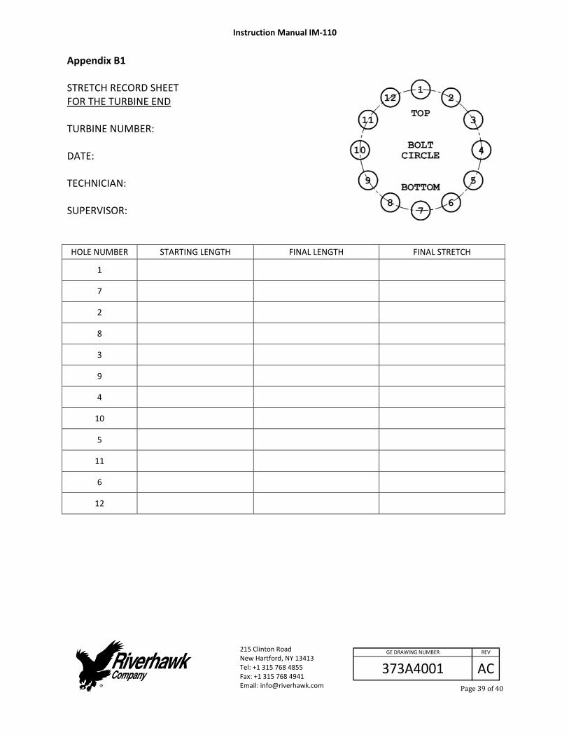
Appendix B1 STRETCH RECORD SHEET FOR THE TURBINE END TURBINE NUMBER: DATE: TECHNICIAN: SUPERVISOR: HOLE NUMBER STARTING LENGTH FINAL LENGTH FINAL STRETCH
1
7
2
8
3
9
4
10
5
11
6
12

Instruction Manual IM‐110
215 Clinton Road New Hartford, NY 13413 Tel: +1 315 768 4855 Fax: +1 315 768 4941 Email: [email protected]
AC
REV
373A4001
GE DRAWING NUMBER
Page40of40
Appendix B2 STRETCH RECORD SHEET FOR THE GENERATOR END TURBINE NUMBER: DATE: TECHNICIAN: SUPERVISOR: HOLE NUMBER STARTING LENGTH FINAL LENGTH FINAL STRETCH
1
10
2
11
3
12
4
13
5
14
6
15
7
16
8
17
9
18