IM-419 (D602) - Riverhawk Companyriverhawk.com/wp-content/uploads/2017/10/IM-419.pdfThe vario with...
36
Applicab D602 Ste Applicab 126T806 126T806 126T806 The River The latest le Bolting Co eam Turbine le GE Orderi 4P0001 4P0002 4P0003 M IS C rhawk Compa t revision may INS onnections HPIP Rotor ing Sheet Pa GE Pow MLI: SSUED: THIS DOCUMENT THE SAME REVIS TH GE NO GE SIGNATURE HECKED: any reserves y be obtained 215 Clint New Har Tel: +1 31 Fax: +1 3 Email: inf STRUCTIO For Gas Tu Stud to LP Rotor art Numbers wer Generat DATE T SHALL BE REVISED IN SION LEVEL AS INDICAT VEN HIS DOCUMENT IS FILE OT TO REVISE. GE REVI ES the right to d by contactin ton Road tford, NY 13413 15 768 4855 15 768 4941 f[email protected]m N MANUA urbine Ten ds and Nut tion E N ITS ENTIRETY. ALL SH TED IN THIS VENDOR S 10 GE D NDOR SUPPLI ED UNDER THE GE DRA SION LEVEL IS SHOWN update this d ng Riverhawk m AL IM‐419 nsioned ts GENERAL ELECTRI _ HEETS OF THIS DOCUM SUPPLIED DRAWING A 00A1467 DRAWING NUMBER ED AWING NUMBER. N ON THIS APPLIQUE. document wi k Company or IC COMPANY ____ OF ____ MENT ARE APPLIQUE. REV ithout dissem r thru www.ri mination or n verhawk.com notice. m.
Transcript of IM-419 (D602) - Riverhawk Companyriverhawk.com/wp-content/uploads/2017/10/IM-419.pdfThe vario with...

Applicab
D602 Ste Applicab126T806126T806126T806
The RiverThe latest
le Bolting Co
eam Turbine
le GE Orderi4P0001 4P0002 4P0003
M
IS
C
rhawk Compat revision may
INS
onnections
HPIP Rotor
ing Sheet Pa
GE Pow
MLI:
SSUED:
THIS DOCUMENTTHE SAME REVIS
TH
GE NO
GE SIGNATUREHECKED:
any reserves y be obtained
215 ClintNew HarTel: +1 31Fax: +1 3Email: inf
STRUCTIOFor Gas Tu
Stud
to LP Rotor
art Numbers
wer Generat
DATE
T SHALL BE REVISED INSION LEVEL AS INDICAT
VEN
HIS DOCUMENT IS FILE
OT TO REVISE. GE REVI
ES
the right to d by contactin
ton Roadtford, NY 13413 15 768 4855 15 768 4941 [email protected]
N MANUAurbine Tends and Nut
tion
E
N ITS ENTIRETY. ALL SHTED IN THIS VENDOR S
10
GE D
NDOR SUPPLI
ED UNDER THE GE DRA
SION LEVEL IS SHOWN
update this dng Riverhawk
m
AL IM‐419nsioned ts
GENERAL ELECTRI
_
HEETS OF THIS DOCUMSUPPLIED DRAWING A
00A1467
DRAWING NUMBER
ED
AWING NUMBER.
N ON THIS APPLIQUE.
document wik Company or
IC COMPANY
____ OF ____
MENT AREAPPLIQUE.
REV
ithout dissemr thru www.ri
mination or nverhawk.com
notice. m.

Sectio
1.0
2.0
3.0
4.0
5.0
6.0
7.0
8.0
9.0
10.0
11.0
12.0
13.0
14.0
AppenA1
AppenB1
on
0
0
0
0
0
0
0
0
0
0
0
0
0
0
ndix
ndix
Scope
Hydra
Thread
16‐Bolt Te
Instructio
215 ClintNew HarTel: +1 31Fax: +1 3Email: inf
Table
De
Cautions an
and GE Part
Quic
Genera
Hardware
Stud and
aulic Tension
Assembly of
Stud
Locking and
Stud an
Storag
Frequently
Revis
EC Declarat
ensioning Pa
on Manual IM
ton Road tford, NY 13413 15 768 4855 15 768 4941 [email protected]
of Conten
escription
nd Safety Wa
t Number Cr
ck Checklist
al Preparatio
Set Prepara
d Nut Assem
ner Equipme
f Tensioner o
d Tensioning
d Windage P
d Nut Remo
ge Instruction
y Asked Que
sion History
tion of Confo
ttern (HPIP‐
‐419
m
nts
arnings
oss Referen
ons
ations
mbly
ent Assembly
on Stud
lug Installat
oval
ns
estions
y
ormity
‐LP) Record S
100A14
GE DRAWING NU
ce
y
ion
Sheet
467
UMBER
Page
Page Num
3
4
5
9
11
14
16
19
22
25
27
31
31
34
35
36
REV
e2of36
mber

1.0 Cauti
Impropecauses oincorrectdeliberattraining n
Risk of higinspect al
Personal procedurapplicabl
The propat a mini
It is espeThread d
Riverhawinspectiorecommeto a plan
A damagrating. Drating, or
To avoid on a studat any pr
ions and Saf
r tool use anf tool failuret hardware ite actions shneeds.
gh pressure fl hoses and c
injury and eres are not fle safety rule
per personal mum, safety
cially importdamage from
wk recommeons. Replaceended. The Rned outage
ged burst diso not substitr a foreign o
failure, ensud in the flangressure unles
fety Warning
nd the failures and persoinstallation hould use hy
fluid injectioconnections
equipment dfollowed. Coes and regul
protective ey glasses, lon
tant to checm previous ab
ends that thement of obsRiverhawk Sto schedule
c must be retute a damabject.
ure safety, age before bless the tool is
Instructio
215 ClintNew HarTel: +1 31Fax: +1 3Email: inf
gs
Wre to follow onal injuriesor incorrectydraulic ten
Won. Riverhaws for damage
Cdamage can ntact the sitations.
Wequipment mng sleeve sh
Cck the conditbuse can lea
Ce tensioner ssolete tensioervice Retur an inspectio
Weplaced withaged burst di
Wand proper oeeding and ps installed on
on Manual IM
ton Road tford, NY 13413 15 768 4855 15 768 4941 [email protected]
WARNING the correct s. A lack of tt tool use. Osioners. Con
WARNING wk tools opee or leaks pr
CAUTION occur if the te’s health a
WARNING must be worirt, hard hat
CAUTION tion of the coad to failure
CAUTION should be reoners is recorns Coordinaon service.
WARNING h a burst discisc with a dif
WARNING operation, thpressurizing n a stud in a
‐419
m
proceduresraining or ex
Only trained ntact Riverh
rate under hior to using
proper healnd safety of
rn at all timet, heavy wor
onical threaof the stud
eturned to Rimmended. Fator should b
c of the samfferent disc
he tensionerthe tension flange.
100A14
GE DRAWING NU
s are the primxperience caoperators whawk Compa
high pressurthis equipm
lth and safetffice to dete
es. Riverhawrk gloves, an
d used to teor tensionin
iverhawk foFunctional ube notified 3
me design andtype, a diffe
r assembly mner. Do not u
467
UMBER
Page
mary root an lead to with careful,any with any
e. Thoroughent.
ty codes andrmine all
wk recommend steel toe s
ension the stng equipmen
r periodic upgrades are3‐6 months p
d pressure erent pressu
must be instause the tensi
REV
e3of36
, y
hly
d
nds shoes
tud. nt
e also prior
re
alled ioner

Personal with the tight in th
The safetkept out
Before thstud's anlubricantthe threa
Do not tibefore atthe tool c
Do not exthe stud
FIRE HAZdamage
Do not u 2.0 Scope This docusets supp The hydrthe safetfactory fo
injury and etapered thrhe stud and
ty cage mustof designate
hreading thend the pullert to the pulleads before ti
ghten the nttempting tocould jump o
xceed the mand puller s
ZARD: DO Nmay occur. U
se a hydraul
e and GE Pa
ument descrplied by the
raulic toolingty guard is YEor assistance
equipment deads of the sthe tension
t be in placeed areas to a
e puller screw screw's coner screw. Thiightening. D
ut while theo tighten theoff the stud
maximum precrew.
OT heat whUse of an Ox
lic tensioner
rt Number C
ribes the proRiverhawk C
g used in thisELLOW, a dife.
Instructio
215 ClintNew HarTel: +1 31Fax: +1 3Email: inf
Cdamage can stud. Properer assembly
We at all timesavoid any po
Cw into the stnical threadsis procedureDo not use “N
C tool is comie nut with thwhile comin
Cessure mark
Wen puller assxy‐Acetylene
Wr to remove
Cross Refere
ocedure to bCompany in
s applicationfferent set o
on Manual IM
ton Road tford, NY 13413 15 768 4855 15 768 4941 [email protected]
CAUTION occur if the r engagemeny is free to tu
WARNING . When the totential for p
CAUTION tud, carefulls. Apply a lige will ease asNever Seize”
CAUTION ing up to prehe spanner rng up to pres
CAUTION ed on the te
WARNING sembly is in e torch is no
WARNING a stud with
ence
be used to inthe flanges a
n can be idenof instruction
‐419
m
puller screwnt is achieveurn.
tensioner is personal inju
y check the ht coat of clssembly and” on the con
essure; waitring. If the tossure.
ensioner. Exc
place. Persot recommen
damaged co
nstall the stuat the HPIP t
ntified by itsns are requir
100A14
GE DRAWING NU
w is not secued when the
pressurizedury.
cleanliness ean turbine d assure posnical threads
t until pressuool is not pro
cessive pres
onal injury onded
onical thread
d, nut, and wto LP connec
s ORANGE sared. Consult
467
UMBER
Page
rely engage puller screw
d hands must
of both the oil or a spraitive mating s.
ure is achievoperly instal
sure can dam
or equipmen
ds.
windage pluctions.
afety guard. t the Riverha
REV
e4of36
d w is
t be
ay of
ved led,
mage
t
ug
If awk

The variowith diffehardwarethis man 2.1 D602
GE Part N
126T806
The hydr These harotor (2‐3 2.2 Hydr
GE Part N
126T806126T806
3.0 Quick The follosupplied Riverhaw
EQUIPM
□ Che
□ Che
□ Che
□ Tes
□ Insp
ous frame coerences as re drawings (ual.
2 Steam Turb
Number
4P0001
raulic tooling
ardware dra3/4” size, Qt
aulic Tooling
Number
4P0002 4P0003
k Checklist
wing checklequipment.
wk equipmen
ENT INSPEC
eck oil level
eck air press
eck hydraulic
st pump.
pect tension
onfigurationselated to coHF‐xxxx). Th
bine HPIP Ro
g used for in
wings depicty 16).
g
ist is intende. New personnt recently a
TION
in hydraulic
sure at 80psi
c hose for da
ner for any d
Instructio
215 ClintNew HarTel: +1 31Fax: +1 3Email: inf
s covered innnective hahese drawing
otor to LP Ro
Riverhaw
HF‐7956
stallation an
ct the stud,
Riverhaw
HT‐7967AP‐6048
ed as a summnnel or thosare encourag
pump.
i [5.5 bar] m
amage.
damage.
on Manual IM
ton Road tford, NY 13413 15 768 4855 15 768 4941 [email protected]
this manuardware defings as well as
otor
wk P/N
6
nd removal i
nut, and wi
wk P/N
7 8
mary of the e experiencged to read t
inimum. (Fo
‐419
m
l are listed ined. Listed as tooling draw
G
G
s Riverhawk
ndage plug
GE
GEGE
steps needeed personnethe entire m
or air‐driven
100A14
GE DRAWING NU
n Sections 2also are the wings (HT‐xx
E VENDOC P
E 101B0709
k HT‐7967.
set for the
E VENDOC P
E 101B0710 E 269B8768
ed to use theel who have manual.
pumps)
467
UMBER
Page
2.1 through 2pertinent xxx) form pa
P/N
9
HPIP rotor
P/N
e Riverhawknot used th
REV
e5of36
2.2
art of
to LP
k‐he

NUT AND
□ Insp
□ Cle
□ Me
□ Lubthr
□ Inst
□ Set
□ Witwre
□ Ver
TENSION
□ Che
□ App“NE
□ Instten
□ Inst
□ Thr
□ Inse
□ Insepulpul
D STUD PREP
pect studs, n
an the studs
easure and re
bricate the steads and nu
tall studs an
t stick‐out di
th Allen wreench.
rify stick‐out
NING (Bolt In
eck tensione
ply a light coEVER SEIZE”
tall the retennsioned.
tall the span
read the pul
ert an Allen
ert another ler screw unler screw an
PARATION
nuts and win
s, nuts, and w
ecord stud le
tud’s threadut face with c
d nuts (off‐c
mension on
nch in backs
t measureme
nstallation)
er drawing fo
oat of clean t ON THE CO
ntion screws
nner ring ont
ler screw int
wrench into
Allen wrencntil hand tighnd leave tigh
Instructio
215 ClintNew HarTel: +1 31Fax: +1 3Email: inf
ndage plugs
windage plu
engths. (VER
ds with cleanclean turbin
center) into
the HPIP sid
side of stud,
ent (VERY IM
or correct pa
turbine oil oONICAL THRE
s into the ad
to the nut.
to the stud.
o the back sid
h into the pht and then ht. DO NOT B
on Manual IM
ton Road tford, NY 13413 15 768 4855 15 768 4941 [email protected]
for any dam
ugs.
RY IMPORTA
n turbine oile oil or spray
the flange.
de of the flan
firmly seat
MPORTANT)
arts and part
or spray lubriEADS.
djacent studs
de of the stu
uller screw. loosen the pBACK OFF PU
‐419
m
mage.
ANT)
or spray luby lubricant.
nge.
backside nu
)
t numbers.
icant to the
s on either s
ud.
While holdipuller screw ULLER SCREW
100A14
GE DRAWING NU
bricant. Lubr
t using span
puller screw
side of the st
ng the stud 1/2 of a turW.
467
UMBER
Page
ricate the nu
nner ring and
w. DO NOT U
tud to be
still, tightenn. Retighten
REV
e6of36
ut’s
d pin
USE
n the n the

□ Slid
□ Thrbet
□ Plascre
□ Tigten
□ The
□ Pusfitt
□ Inst
□ Concor
□ Usetor
□ Rel
□ Disfitt
□ Rem
□ Loo
□ Uns
□ Rem
□ Mopre
□ Rep
de the correc
read the tentween the fo
ce the guardews.
hten the guansioner (no g
e retention s
sh the centeing’s pull tab
tall the back
nnect the hyrrect pressur
e the pin wreque.
ease pressu
connect theing towards
move the ba
osen the knu
screw the te
move the foo
ove to the neessure.
peat above s
ct foot over
sioner onto oot and tens
d over tensio
ard’s knurledgap).
screws must
r of the intebs until it loc
kside guard t
ydraulic pumre.
ench to turn
re and allow
hose and rethe tension
ackside guard
urled interloc
ensioner from
ot, puller scr
ext stud in th
steps at fina
Instructio
215 ClintNew HarTel: +1 31Fax: +1 3Email: inf
the puller st
puller screwioner.
oner and pos
d interlock f
be inside th
rlock fitting cks onto the
to cover stud
mp to the ten
n the spanne
w the tension
elease the iner while pul
d.
ck fitting and
m the puller
rew, spanne
he pattern. T
l pressure.
on Manual IM
ton Road tford, NY 13413 15 768 4855 15 768 4941 [email protected]
tud and orie
w until it stop
sition the gu
itting by han
he guard’s po
towards the tensioner a
d to be tensi
nsioner and t
er ring to firm
ner to fully r
nterlock fittinling back on
d remove th
r screw.
er ring, and t
Tension all st
‐419
m
entate the fo
ps. There sh
uard’s pocke
nd until it pr
ocketed slot
e tensioner wand release t
ioned.
tension to 5
mly tighten n
retract.
ng by pushinn the fitting’s
he guard.
the retention
tuds to 50%
100A14
GE DRAWING NU
oot into posit
ould be a 1/
eted slots int
resses firmly
ts.
while pullingthe pull tabs
50%. Consult
nut with 20 f
ng the centes pull tabs.
n screws.
% before proc
467
UMBER
Page
tion.
/16” to 3/16
to retention
y against
g back on ths.
t manual for
ft∙lbs [27 N∙m
er of the inte
ceeding to fi
REV
e7of36
6” gap
e
m] of
erlock
inal

□ Meme
□ Tor
□ Inst
DETENSI
□ Loo
□ Loo
□ Inspfrorem
□ App“NE
□ Instten
□ Inst
□ Thr
□ Inse
□ Insepulpul
□ Slid
□ Thrbet
□ Plascre
easure final sasurement.
rque the nut
tall the wind
ONING (Stu
osen the win
osen nuts' se
pect and clem the threamove a dama
ply a light coEVER SEIZE”
tall the retennsioned.
tall the span
read the pul
ert an Allen
ert another ler screw unler screw an
de the correc
read the tentween the fo
ce the guardews.
stud length a
ts' set screw
dage plugs a
d Removal)
ndage plugs’
et screws.
an studs' coads! See instaged stud!
oat of clean t ON THE CO
ntion screws
nner ring ont
ler screw int
wrench into
Allen wrencntil hand tighnd leave tigh
ct foot over
sioner onto oot and tens
d over tensio
Instructio
215 ClintNew HarTel: +1 31Fax: +1 3Email: inf
and record o
s.
nd torque th
set screws a
onical threadtruction man
turbine oil oONICAL THRE
s into the ad
to the nut.
to the stud.
o the back sid
h into the pht and then ht. DO NOT B
the puller st
puller screwioner.
oner and pos
on Manual IM
ton Road tford, NY 13413 15 768 4855 15 768 4941 [email protected]
on stretch da
heir set screw
and remove
ds. Do not conual IM‐220
or spray lubriEADS.
djacent studs
de of the stu
uller screw. loosen the pBACK OFF PU
tud and orie
w until it stop
sition the gu
‐419
m
atasheets. C
ws.
the windag
ontinue unt. Do not try
icant to the
s on either s
ud.
While holdipuller screw ULLER SCREW
entate the fo
ps. There sh
uard’s pocke
100A14
GE DRAWING NU
Calculate fina
e plugs from
til ALL debrisy to use the
puller screw
side of the st
ng the stud 1/2 of a turW.
oot into posit
ould be a 1/
eted slots int
467
UMBER
Page
al stretch
m the studs.
s is removedtensioner to
w. DO NOT U
tud to be
still, tightenn. Retighten
tion.
/16” to 3/16
to retention
REV
e8of36
d o
USE
n the n the
6” gap

□ Tigten
□ The
□ Pusfitt
□ Inst
□ Conma
□ Loo
□ Rel
□ Disfitt
□ Rem
□ Loo
□ Uns
□ Remnecscre
□ Mo
4.0 Gene Read and Operatorequipme
hten the guansioner (no g
e retention s
sh the centeing’s pull tab
tall the back
nnect the hynual for cor
osen nut wit
ease pressu
connect theing towards
move the ba
osen the knu
screw the te
move the foocessary to inew.
ove to next s
eral Preparat
d understand
rs should beent. Training
ard’s knurledgap).
screws must
r of the intebs until it loc
kside guard t
ydraulic pumrect pressur
h the spann
re and allow
hose and rethe tension
ackside guard
urled interloc
ensioner from
ot, puller scrsert an Allen
tud in patte
tions
d all instruct
trained or hwill minimiz
Instructio
215 ClintNew HarTel: +1 31Fax: +1 3Email: inf
d interlock f
be inside th
rlock fitting cks onto the
to cover stud
mp to the tenre.
er ring and p
w the tension
elease the iner while pul
d.
ck fitting and
m the puller
rew, spannen wrench int
rn
tions before
have previouze the chanc
on Manual IM
ton Road tford, NY 13413 15 768 4855 15 768 4941 [email protected]
itting by han
he guard’s po
towards the tensioner a
d to be tensi
nsioner and t
pin wrench.
ner to fully r
nterlock fittinling back on
d remove th
r screw.
er ring, and tto the backs
installing an
us experiencce of improp
‐419
m
nd until it pr
ocketed slot
e tensioner wand release t
ioned.
tension to fi
retract.
ng by pushinn the fitting’s
he guard.
the retentionide of the st
nd tensionin
ce using Riveper use of th
100A14
GE DRAWING NU
resses firmly
ts.
while pullingthe pull tabs
inal pressure
ng the centes pull tabs.
n screws. It mtud to remov
ng studs.
erhawk tensie equipmen
467
UMBER
Page
y against
g back on ths.
e. Consult
er of the inte
may be ve the puller
ioning nt.
REV
e9of36
e
erlock
r

The hydrguideline This equiexercise operating High‐prelarge forcThe nut iflange, thtogether 4.1 Mach The flangTurning tremove aplates, an 4.2 Hard The studin its set one set wnot assigthe insta2.0). The nuts its set wiset with assigned installatio A weightappropri 4.3 Tensi When noplugs for
raulic toolinges are listed
ipment prodcaution andg the hydrau
ssure oil froce that actuas then turnehe pressure .
hine Prepara
ge to be tensthe turbine sas many obsnd conduit.
ware – Bala
s are suppliewithout affewith anothergned to any sllation site. T
are suppliedthout affectanother nutto any specon site. The
t balance cerate location
ioner – Care
ot in use, the hydraulic o
g including tin the follow
duces very h wear the apulic tooling.
m the hydraally stretcheed by hand uin the tensio
ation
sioned mustshafts is not structions as
nce
ed in compoected the ovr stud from aspecific holeThe set size
d in componted the over from a diffecific hole in tset size is de
rtification is as it will be
e and Handli
e tensioner spenings and
Instructio
215 ClintNew HarTel: +1 31Fax: +1 3Email: inf
he hydraulicwing sub‐sec
igh hydraulippropriate p
aulic pump pes the stud. Ausing the suponer is relea
t be fully closrequired, bu possible fro
onent balancverall balanca different se in the load is determine
nent balanceall balance oerent set. Whe load couetermined b
supplied wit needed for
ing
shall be maind fittings mus
on Manual IM
ton Road tford, NY 13413 15 768 4855 15 768 4941 [email protected]
c hoses shouctions.
c pressures personal pro
pressurizes tAs the stud ipplied spannsed. The har
sed prior to ut may be usom the flang
ced sets. A ste of the equet. When shcoupling flaed by the re
ed sets. A nuof the equiphen shippedpling flange;by the releva
th each ordethe purchas
ntained in a st be in plac
‐419
m
uld be inspec
and very higtective equi
he tensioneis stretched ner ring. Oncrdware is no
positioning seful. Also, ige area, such
tud can be euipment. Do hipped from nge; this is oelevant GE o
ut can be excment. Do nod from River; this is optioant GE order
er. Store thisse of replace
clean enviroce.
100A14
GE DRAWING NU
cted prior to
gh forces. Opment whe
r which genthe nut lifts ce the nut isow clamping
of studs in tit will be advh as speed p
exchanged wnot exchangRiverhawk, optional andrder drawing
changed witot exchange rhawk, the nonal and canr drawing (se
s certificatioement equip
onment and
467
UMBER
Page1
o use. Inspec
Operators mun handling a
erates a ver off the flang tight againsg the flange
the flanges. vantageous trobes, shipp
with another ge a stud frothe studs ard can be dong (see sectio
h another na nut from outs are not n be done atee section 2.
on in an pment.
all caps and
REV
10of36
ction
ust and
y ge. st the
to ping
stud om re ne at on
ut in one
t the .0).
d

Use ISO 3 When in See secti 4.4 Hand Several hmeasure 5/8” Wre3/4” WreA set of A3’ to 4’ B12” to 13 4.5 Speci
Hydraulic
Hydraulic
Riverhawinspectioalso recomonths p 5.0 Hard
32 grade oil.
use, the ten
on 12 for lo
d Tools
hand wrenchment of the
ench ench Allen WrencBreaker Bar 3” Micromet
ial Tools
c Tensioner
c Pump Kit:
wk recommeons. Replaceommended. prior to a pla
ware Set Pr
.
nsioner shall
ng term stor
hes and micr studs:
hes
ter or Calipe
Kit:
ends that thement of ob The Riverhanned outag
eparations
Instructio
215 ClintNew HarTel: +1 31Fax: +1 3Email: inf
be protecte
rage require
rometers ma
r
HT‐
AP‐
Ce tensionersbsolete tensawk Servicege to schedu
on Manual IM
ton Road tford, NY 13413 15 768 4855 15 768 4941 [email protected]
ed from sand
ements.
ay be require
‐7967 Hydra (reference
‐6048 Air‐Op (reference
CAUTION s be returneioners is rece Returns Coule an inspe
‐419
m
d and grit.
ed to perfor
aulic Tensione GE VENDOC
perated Hyde GE VENDOC
ed to Riverhcommendedoordinator section servic
100A14
GE DRAWING NU
rm installatio
ner, 2‐3/4” C 101B0710
draulic PumpC 269B8768
awk for perd. Functionashould be noce.
467
UMBER
Page1
on and
0)
p )
riodic al upgrades otified 3‐6
REV
11of36
are

5.1 Nut P
If there isfor a repand digit 5.1.1 Nut
For new 5.1.2 Nut
Previoussolvent t 5.2 Stud
Check thcontact tturbine n
It is espestud. Threquipme
The conicThis ensu
(S
Preparation
s any visiblelacement nual photograp
t Cleaning ‐
installations
t Cleaning ‐
ly installed no remove an
Preparation
e stud for anthe Riverhawnumber, wei
ecially imporread damagent.
cal threads oures the pro
(2) Locking Set Screws
damage on ut. Please bephs for evalu
New Installa
s, the nuts sh
Old Installa
nuts require ny foreign m
n
ny visible dawk Companyght certifica
rtant to chece from prev
of each studper seating o
Instructio
215 ClintNew HarTel: +1 31Fax: +1 3Email: inf
Picture 5A ‐
a nut, do noe prepared touation.
ations
hould come
tions
cleaning as material on th
mage. If they for a replacation, and dig
Cck the condivious abuse c
must be cleof the puller
on Manual IM
ton Road tford, NY 13413 15 768 4855 15 768 4941 [email protected]
‐ Riverhawk
ot use the nuo supply the
sealed from
follows: Wirhe external s
ere is any viscement studgital photog
CAUTION ition of the can lead to f
ean of grit anr screw.
‐419
m
Locknut
ut and contae turbine num
m the factory
re brush usinsurfaces and
sible damaged. Please be graphs for ev
conical threfailure of th
nd dirt befor
100A14
GE DRAWING NU
act the Rivermber, weigh
y and will ne
ng a petroled threads.
e, do not useprepared tovaluation.
ead used to the stud or te
re installatio
(2R
467
UMBER
Page1
rhawk Compht certificatio
ed no cleani
eum‐based
e the stud ano supply the
tension the ensioning
on or remova
2) SpannerRing Holes
REV
12of36
pany on,
ing.
nd
al.

5.2.1 Stu For new 5.2.2 Stu Previousshiny app If cleanin
1. Bthch
2. U
3. Inat
4. W
thp
5. B
6. V
7. R
8. In
9. D
10. Fst
ud Cleaning ‐
installations
ud Cleaning ‐
ly installed spearance.
ng is required
low out the hreads. Do nhemically at
Use Stud Clea
nsert the brut high speed
Work the drilhreads. Try nrotective co
low out the
Visually inspe
epeat if any
nspect threa
Do not apply
inish the cletud to dry.
‐ New Instal
s, the studs s
‐ Old Installa
studs may re
d, follow the
threads witnot apply a stack the stu
aning Kit, GT
ush into an ed.
l in a circulanot to hold tating.
threads wit
ect threads f
dirt can be
ds for any d
“Never Seiz
aning proce
Instructio
215 ClintNew HarTel: +1 31Fax: +1 3Email: inf
llations
should come
ations
equire cleani
ese steps:
h compresseolvent or otd.
T‐4253 or a s
Picture 5B ‐
electric drill a
ar motion whthe brush in
h compresse
for cleanline
seen in the t
amage that
ze” to the stu
ss by rinsing
on Manual IM
ton Road tford, NY 13413 15 768 4855 15 768 4941 [email protected]
e sealed from
ing. Clean co
ed air to remher cleaning
similar 1" dia
‐ Brass Powe
and set drill
hile moving tone place to
ed air to rem
ss. Threads
threads.
may have b
ud’s threads
g in a volatile
‐419
m
m the factor
onical thread
move loose dg solution to
ameter Bras
er Brush
to run in a c
the brush inoo long, so a
move loosen
should be b
een caused
s.
e solvent suc
100A14
GE DRAWING NU
ry and will ne
ds should ha
debris and do the threads
s power bru
counterclock
n and out to as not to rem
ed debris.
right and sh
by previous
ch as aceton
467
UMBER
Page1
eed no clean
ave a bright
ry conical s as this may
ush.
kwise direct
clean all of tmove the stu
iny.
s installation
ne and allow
REV
13of36
ning.
and
y
ion
the ud's
.
w the

5.3 Stud Measure
P
St
N
M
M
R
D
T 6.0 Stud
Refer to
1. A
2. Lu
3. Lu
4. S
Length Mea
e and record
lan to start
tuds and fla
Number each
Mark the loca
Measure eac
Record each
Do not allow
he same pe
and Nut Ass
the hardwar
Assemble the
ubricate the
ubricate the
lide the stud
asurement
the initial st
and finish a
nge must be
h stud with a
ation of mea
h stud to ne
measureme
the measur
rson should
sembly
re assembly
e cylindrical
e stud’s threa
e nut’s threa
d and cylindr
Instructio
215 ClintNew HarTel: +1 31Fax: +1 3Email: inf
tud lengths.
ny flange in
e at the sam
a marker for
asurement o
earest 0.001
ent on the su
ring instrum
make all m
drawing (HF
nut to the in
ads with clea
ds and nut f
rical nut asse
on Manual IM
ton Road tford, NY 13413 15 768 4855 15 768 4941 [email protected]
The followin
n the same d
me temperat
r later stretc
on stud end
inch (.01 m
upplied reco
ments to sit i
easurement
F‐xxxx) listed
nternal, coni
an turbine o
face with cle
embly into t
‐419
m
ng suggestio
day.
ture.
ch measurem
d with a perm
mm).
ord sheets.
n the sun.
ts.
d in Section
ical thread e
oil or spray lu
ean turbine o
the flange as
100A14
GE DRAWING NU
ons will impr
ment trackin
manent mar
2.0 of the m
end of the st
ubricant.
oil or spray l
s shown in F
467
UMBER
Page1
rove your re
ng.
rker.
manual.
ud.
ubricant.
igure 6A.
REV
14of36
sults.

5. In
6. AthTAp
HP
TConic
* Set Stuon th
Fi
nstall the oth
Adjust the nuhe cylindricaHIS PROTRUA metal stick‐rotrusion di
PictureNote
Fro
PIP Rotor Flange
Tensioning cal Thread ud Stick‐out his side only
igure 6A – Cr
her nut on th
ut/stud assemal nut the disUSION OF ST‐out gage is mension.
e 6B – Use oe: The D202
ont Side Nut
Instructio
215 ClintNew HarTel: +1 31Fax: +1 3Email: inf
oss‐section VLP Rotor Bolt
he backside.
mbly so thatstance specifTUD TO NUTprovided wi
of Stick‐Out Gstick‐out gag
t
on Manual IM
ton Road tford, NY 13413 15 768 4855 15 768 4941 [email protected]
View of Steamted Flange Co
.
t the stud prfied on the hT IS CRITICALith the tensio
Gage on the ge is used on
‐419
m
m Turbine HPIonnection
rotrudes (or hardware drL FOR PROPEoner to assis
D602 HPIP‐n this specia
Stud
100A14
GE DRAWING NU
IP Rotor to
sticks out) frawing (HF‐xER TENSIONst the opera
LP Flange Joal application
Back Si
467
UMBER
Page1
from the facxxxx). SETTINNER OPERATator in settin
oint n
Hex Drive
de Nut
LP RotoFlange
REV
15of36
e of NG TION. g the
r

7. W
p
8. Rd
7.0 Hydr 7.1 Hydr 7.1.1 Hyd
RiverhawReplacemrecommeprior to a This tens
To avoidinstalledthe tensi Clean pu
Picture 6m
With Allen wrin wrench.
echeck the srawing, adju
aulic Tensio
aulic Equipm
draulic Tens
wk recommement of obsoended. The a planned o
sioner does n
failure, ens on a stud inioner at any
ller screw an
6C – Use of measure stic
rench in bac
stud stick‐ouust the nuts
oner Equipm
ment Inspec
sioner Inspec
ends that tholete tensioRiverhawk Sutage to sch
not require b
sure safety, an the flange y pressure un
nd check for
Instructio
215 ClintNew HarTel: +1 31Fax: +1 3Email: inf
Drop Gage tck‐out
ckside of stud
ut length. If tas necessary
ment Assemb
tion
ction
Ce tensioneroners is recoService Retuhedule an in
bleeding. Se
Wand proper before bleenless the too
r any debris
on Manual IM
ton Road tford, NY 13413 15 768 4855 15 768 4941 [email protected]
to
d, firmly sea
the stick‐outy.
bly
CAUTION be returned
ommended. urns Coordinspection ser
e section 8.3
WARNING operation, teding and prol is installe
and dents.
‐419
m
Picture 6m
at backside n
t length doe
d to RiverhaFunctional unator shouldrvice.
3
the tensioneressurizing ted on a stud
100A14
GE DRAWING NU
6D – Use of easure stick
nut using spa
es not match
awk for perioupgrades ard be notified
er assemblythe tensionein a flange.
467
UMBER
Page1
Calipers tok‐out
anner ring a
h the hardwa
odic inspectre also d 3‐6 month
y must be er. Do not us
REV
16of36
nd
are
tions.
hs
se

Inspect tmodifiedrubber p Inspect tand inter Perform providedReplacem 7.1.1.1 H The hydrtensioneHT‐xxxx l Each tenand withRiverhaw To replac
1. R2. D3. C
so4. R
h
A damagrating. Drating, o 7.1.2 Hyd Refer to revision m
he tensioned in the field ad is in place
he outside ornal damage
an inventoryd on the tensment parts a
Hydraulic Ten
raulic tensionr. The burst listed in sect
sioner is shi another spawk for replac
ce a damageemove the h
Discard the dlean the dispolvent to eneassemble nydraulic por
ged burst disDo not substir a foreign o
draulic Pum
the Hydraulmay be obta
r guard for ashould be ree on the bac
of the tensioe.
y of the loossioner’s techre available
nsioner’s Bu
ner’s burst ddisc’s locatition 2.0 and
pped from oare disc for fcement purp
ed burst dischydraulic poamaged burpersion nut,sure a dirt‐fnew burst dirt.
sc must be ritute a damaobject.
p Kit Inspec
ic Pump Kit ained by con
Instructio
215 ClintNew HarTel: +1 31Fax: +1 3Email: inf
any signs of eplaced. Benck side guard
oner for disco
se equipmenhnical drawinfrom Riverh
urst Disc Rep
disc is a key eon is shown4.5).
our factory wfield replaceposes.
: ort’s dispersirst disc. compressioree installatisc, compres
Weplaced witaged burst d
ction
Instruction Mntacting Rive
on Manual IM
ton Road tford, NY 13413 15 768 4855 15 768 4941 [email protected]
damage inclnt guards shd, if missing,
oloration pa
nt supplied wng (Riverhawhawk.
placement
element in t on the tens
with one burement. Extra
on nut, com
on ring, new ion. ssion ring, an
Warning th a burst disdisc with a d
Manual, IM‐erhawk Comp
‐419
m
luding crackhould be rep, replace.
atterns that m
with the tenswk HT‐xxxx li
the overall ssioner’s tech
rst disc alreaa burst discs
mpression rin
burst disc, a
nd dispersio
sc of the samdifferent dis
‐293 (GE VENpany or thru
100A14
GE DRAWING NU
ed welds. Anlaced. Also,
may indicate
sioner. An inisted in sect
afe use of thhnical drawin
ady installedare availabl
ng, and dama
and the hyd
n nut into th
me design ac type, a dif
NDOC 373A4u www.river
467
UMBER
Page1
ny guards be sure the
e submersio
nventory listion 2.0 and
he hydraulicng (Riverhaw
in the tensie from
aged burst d
raulic port w
he same
nd pressurefferent press
4058). The lahawk.com.
REV
17of36
on
t is 4.5).
wk
oner
disc.
with a
e sure
atest

7.2 Hydr
Illustratio
Illustratio
Illustratio
aulic Fitting
on 1
on 2
on 3
s
Instructio
215 ClintNew HarTel: +1 31Fax: +1 3Email: inf
on Manual IM
ton Road tford, NY 13413 15 768 4855 15 768 4941 [email protected]
Riverhawk hPressure pohose conneassembly: a1/4” hose e To assemblythe 1/4” tubcounter‐clotube or hos
The collar sthe tip of thnecessary tgrip pliers. the tube or
Slide the glaIllustration end into thefirmly holdirotating, tuthread) andN‐m). Tips: Make su
debris. Protect
or 1/4” sealing s
Replaceprotect
‐419
m
hydraulic puort to connecector is madea gland nut, aend. (See Illu
y the fitting,be or 1/4” hockwise (left se end as sho
hould be plahe cone. (Seeo adjust thisBe careful those end.
and nut dow3) Insert the tensioner’ng the tube rn the glandd torque the
ure all parts
the cone onhose end frosurface. e red plastic the threads
100A14
GE DRAWING NU
umps use a 1ct its hydraue from a threa collar, andustration 1)
, slide the glhose end. Tuhand threaown in Illust
aced .125” (3e Illustrations collar with to not strip t
wn over the ce 1/4” tube s quick coupor hose end
d nut clockw gland nut to
are clean an
n the end of om scratche
caps when fs and cone.
467
UMBER
Page1
1/4” High ulic hoses. Thee piece d a 1/4” tube
and nut overn the collard) on to theration 1.
3.2 mm) fron 2) It may ba set of visehe threads o
collar. (See or 1/4” hosepler. While d to stop it frise (right hao 25 FT‐LBS
nd free from
the 1/4” tubes as this is t
finished to
REV
18of36
he
e or
er r
m be e‐off
e
rom and (34
m
be he

8.0 Assem The tenstensioneRiverhaw 8.1 Hand The tensnot drop 8.2 Kit As Connect Refer to tensionetensione
mbly of Ten
ioner used ir’s safety guwk factory fo
dling of the T
ioner used i any part of
ssembly
the hydraul
the hardwarr assembly dr must be as
sioner on a
n this applicuard is YELLOor assistance
Tensioner
n this applicthe tension
ic hose from
re assembly drawing (HT‐ssembled on
Instructio
215 ClintNew HarTel: +1 31Fax: +1 3Email: inf
Stud
ation can beOW, a differe.
ation is desier on the op
m the hydrau
drawing (HF‐xxxx) listed n the load co
on Manual IM
ton Road tford, NY 13413 15 768 4855 15 768 4941 [email protected]
e identified bent set of ins
igned to reqperator or ot
ulic pump to
F‐xxxx) listedin Section 4
oupling for it
‐419
m
by its ORANGstructions ar
uire no specther nearby
the tension
d in Section 4.5 of this mats correct op
100A14
GE DRAWING NU
GE safety gure required.
cial lifting inspersonnel.
er.
2.0 of this manual to detperation.
467
UMBER
Page1
uard. If the Consult the
structions. D
manual and ttermine how
REV
19of36
Do
the w the

Conne
Con
Interloc
P
Fi
Safety Guard
Hose ection
Safet
Hose nnection
Knurled ck Fitting
Hydr
Picture 8A –
igure 8B – C
ty Guard
raulic Cylinde
Instructio
215 ClintNew HarTel: +1 31Fax: +1 3Email: inf
Features of
utaway view
Foot
er Spanner
on Manual IM
ton Road tford, NY 13413 15 768 4855 15 768 4941 [email protected]
the Hydraul
w of Hydraul
HydrauCylinde
Pur Ring
‐419
m
ic Tensioner
lic Tensioner
ulic er
Pin Wrenc
uller Screw
100A14
GE DRAWING NU
r HT‐7967
r HT‐7967
ch
BSa
467
UMBER
Page2
Foot
Pin Wre
HPIP RotFlange
ackside afety Guard
RetenScrew
REV
20of36
ench
tor
ntion w

Note: Bethe stud'spray lubprocedur Assembly1. Open
from hydra
2. Threatensi
3. Place
4. Inser
5. Insercross
6. Usingturn. PULL
7. Place
9. Threinside1/16”THE F
10. Placereten
11. TightThere
12. The r
13. Activthumforwathumthe p
efore thread's and the pubricant to thre will ease
y sequence in the hydrauthe puller toaulic pump)
ad the retenoned until h
e the spanne
t the puller s
t the puller ss‐thread the
g an Allen wrRetighten tER SCREW.
e the foot ov
ad the tensie the tension”[1.6mm] toFOOT.
e the orangention screws
en the knure should be
retention scr
ate the custmb and pullinard until it lo
mb, Ensure copump.
ing the pulleuller screw'she puller screassembly an
is as followsulic return vaool into the
ntion screws and tight.
er ring on the
screw releas
screw into tpuller screw
rench, tightehe puller scr
ver the pulle
oner onto thner will causo 3/16”[4.8m
guard over .
led interlockno gap betw
rews must b
om connectng the tabs wocks into theonnection is
Instructio
215 ClintNew HarTel: +1 31Fax: +1 3Email: inf
er screw ints conical threw. Do not und assure po
: alve on the ppump reser
into the adj
e nut.
se tape per R
he tapered tw.
en the pullerrew by hand
r screw and
he puller scrse a gap in bmm]. DO NOT
the tensione
k fitting by hween the ten
e inside the
tor from the with your fore tensioner. firmly enga
on Manual IM
ton Road tford, NY 13413 15 768 4855 15 768 4941 [email protected]
o the stud, creads. Applyuse “Never ositive mati
pump to allovoir. (This is
acent studs
Riverhawk m
thread of the
r screw and d until it is fu
orientate it
rew until it sbetween the T ATTEMPT
er and posit
and until it fnsioner the i
guard’s poc
rear of guarre finger andRelease fingged or else t
‐419
m
carefully chey a light coatSeize” on thng of the th
ow hydraulic s automatic o
on either si
manual IM‐3
e stud and h
then back oully inserted.
into positio
tops. Pleasefoot and teTO TIGHTEN
ion the pock
firmly pressenterlock fitt
cketed slots.
rd by pushind middle finggers from thethe tensione
100A14
GE DRAWING NU
eck the cleat of clean tuhe conical threads befor
fluid to be pon the air‐op
de of the stu
36.
hand tighten
off the puller. DO NOT BA
n.
e note that tnsioner. TheN THE TENSI
keted slots i
es against thing.
ng on the cenger. Push thee tabs and ter will not be
467
UMBER
Page2
anliness of burbine oil or hreads. This re tightening
pushed backperated
ud to be
n. Be sure no
r screw 1/2 aACK OFF THE
he internal se gap shouldIONER AGAI
nto the
he tensioner
nter with yoe assembly hen removee connected
REV
21of36
both a
g.
k
ot to
a E
stop d be INST
r.
our
e d to

14. In
th
15. Cas
8.3 Bleed Bleeding 9.0 Stud The studtensioninthis man 9.1 Tensi After theto the 50
nstall the bahe stud to be
onnect the hssembled an
ding Hydrau
of the hydra
Tensioning
s will be tenng sequenceual.
ioning at 50
e tensioner is0% level in ac
Pictu
ckside guarde tensioned
hydraulic pund ready for
lic System
aulic system
sioned in twe for each fla
% pressure
s properly inccordance w
Instructio
215 ClintNew HarTel: +1 31Fax: +1 3Email: inf
ure 8C ‐ Activ
d by attachinand lightly t
ump to the teuse.
m is not nece
wo steps, at 5ange joint as
nstalled applwith the follo
Pull tabs with fingers
on Manual IM
ton Road tford, NY 13413 15 768 4855 15 768 4941 [email protected]
vation of the
ng it to the fthreaded int
ensioner. Th
ssary with th
50% pressurdefined on
ly hydraulic owing table.
‐419
m
e safety inte
lange face. Ito backside o
he tensioner
his tensione
re and at finathe record s
pressure to
Pull tawith fing
Pushwith
100A14
GE DRAWING NU
rlock
It should be of the adjace
r should now
er design.
al pressure. sheets found
the tool. Bri
bs gers
h center h thumb
467
UMBER
Page2
centered ovent studs.
w be complet
Follow the d at the end
ing the press
REV
22of36
ver
tely
of
sure

The safetwhen the
Before thstud's anlubricantthe threa
Do not edamage
Do not tibefore atinstalled
Flang
D602 StHP
Firmly tigwrench a 9.2 Remo The tens
1. RPo
2. R
3. Uth
4. U
5. R
ty cage muse tensioner
hreading thend the pullert to the pulleads before t
xceed the mthe stud and
ighten the nttempting to, the tool co
ge Position
team TurbinPIP to LP
ghten the cyand spanner
oving the Te
ioner removelease the hump Kit or bpen.
emove the b
Unscrew the he tensioner
Unscrew the
emove foot
st be in placeis pressurize
e puller screr screw's coner screw. Thtightening. D
maximum prd puller scre
nut while theo tighten thould jump of
Stu
ne 2[71
ylindrical nut ring. Turn t
ensioner fro
val is accomphydraulic preby opening t
backside gua
knurled inter.
tensioner fr
from aroun
Instructio
215 ClintNew HarTel: +1 31Fax: +1 3Email: inf
We at all timeed otherwis
Cew into the snical threadhis procedurDo not use “
Cressure markew.
Ce tool is come nut with tff the stud w
ud Size
‐3/4" 1 mm]
ts with approhe nut until
m an Install
plished by thessure by eithe valve on
ard.
erlock fitting
rom puller sc
d the puller
on Manual IM
ton Road tford, NY 13413 15 768 4855 15 768 4941 [email protected]
WARNING s. Keep hanse personal i
CAUTION stud, carefus. Apply a lire will ease a“Never Seize
CAUTION ked on the t
CAUTION ming up to pthe spanner while coming
50% Pre
11500[800 b
oximately 20it bottoms o
ed Stud
he follows stther releasinthe MP‐013
g at the end o
crew.
screw.
‐419
m
ds out of deinjury can oc
lly check theight coat of assembly ane” on the con
tensioner. Ex
ressure; waring. If the tg up to pres
essure
0 psi bar]
0 ft∙lbs [27 Non the flange
teps: ng the hand s30 Manual P
of the guard
100A14
GE DRAWING NU
esignated arccur.
e cleanlinesclean turbinnd assure ponical thread
xcessive pre
it until prestool is not pssure.
50%
Do noDo
N∙m] of torque.
switch on thump Kit and
d and remov
467
UMBER
Page2
reas at all tim
s of both thne oil or a spositive matinds.
essure can
ssure is achieproperly
% Stretch
ot measurenot use
ue using the
he AP‐0532 d leave the v
ve the guard
REV
23of36
mes
e pray ng of
eved
e pin
alve
from

6. UhD
7. R
8. UAD
9. Mre
9.3 Tensi Repeat thhave beevalues ar
The safetwhen the
Before thstud's anlubricantthe threa
Do not edamage
Do not tibefore atinstalled
Flang
D602 StHP
Unscrew the ammer or th
Do not use an
emove the s
Unscrew the Allen wrenchDo not use an
Move the tooecord sheets
ioning at Fin
he pulling anen tensionedre listed in th
ty cage muse tensioner
hreading thend the pullert to the pulleads before t
xceed the mthe stud and
ighten the nttempting to, the tool co
ge Position
team TurbinPIP to LP
puller screwhe use of a 3n impact wre
spanner ring
retention sc with a hamn impact wre
ol to the nexs at the end
nal Pressure
nd tightenind, measure the following
st be in placeis pressurize
e puller screr screw's coner screw. Thtightening. D
maximum prd puller scre
nut while theo tighten thould jump of
Stu
ne 2[71
Instructio
215 ClintNew HarTel: +1 31Fax: +1 3Email: inf
w using an Al3‐4’ breaker ench as this
g from the nu
crews using amer or use aench as this
xt bolt hole fof this manu
g procedurehe final studg table.
We at all timeed otherwis
Cew into the snical threadhis procedurDo not use “
Cressure markew.
Ce tool is come nut with tff the stud w
ud Size
‐3/4" 1 mm]
on Manual IM
ton Road tford, NY 13413 15 768 4855 15 768 4941 [email protected]
llen wrench.bar may be can damage
ut.
an Allen wrea 3‐4’ breakecan damage
ollowing theual.
e stated abovd length. The
WARNING s. Keep hanse personal i
CAUTION stud, carefus. Apply a lire will ease a“Never Seize
CAUTION ked on the t
CAUTION ming up to pthe spanner while coming
Final Pre
23000[1585
‐419
m
. Tapping thenecessary toe the puller s
ench. It may er bar to looe the retenti
e tensioning
ve at full pree final press
ds out of deinjury can oc
lly check theight coat of assembly ane” on the con
tensioner. Ex
ressure; waring. If the tg up to pres
essure
0 psi bar]
100A14
GE DRAWING NU
e Allen wreno loosen thescrew.
be necessaosen the reteion screws.
pattern fro
essure. Afterure and requ
esignated arccur.
e cleanlinesclean turbinnd assure ponical thread
xcessive pre
it until prestool is not pssure.
Fina
0.019[0.48 mm
467
UMBER
Page2
nch with a e puller screw
ry to tap theention screw
m the stretc
r all of the stuired stretch
reas at all tim
s of both thne oil or a spositive matinds.
essure can
ssure is achieproperly
al Stretch
9" ‐ 0.022" m ‐ 0.56 mm
REV
24of36
w.
e ws.
ched
tuds h
mes
e pray ng of
eved
m]
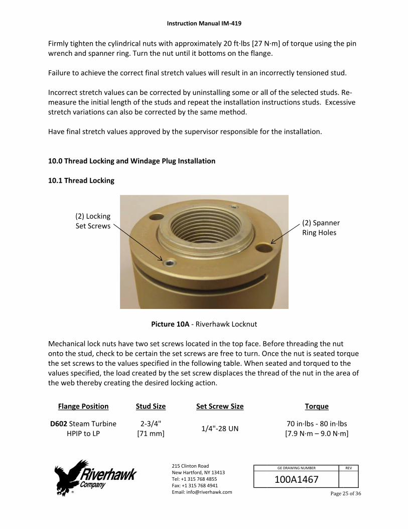
Firmly tigwrench a Failure to Incorrectmeasurestretch v Have fina 10.0 Thre 10.1 Thre
Mechanionto the the set scvalues spthe web
Flange
D602 SteHP
(S
ghten the cyand spanner
o achieve th
t stretch valu the initial leariations can
al stretch va
ead Locking
ead Locking
cal lock nutsstud, checkcrews to thepecified, the thereby crea
e Position
eam TurbineIP to LP
(2) Locking Set Screws
ylindrical nut ring. Turn t
e correct fin
ues can be cength of the n also be co
lues approve
and Windag
P
s have two s to be certaie values specload createating the de
Stud
e 2‐3/[71 m
Instructio
215 ClintNew HarTel: +1 31Fax: +1 3Email: inf
ts with approhe nut until
nal stretch va
corrected by studs and rerrected by th
ed by the su
ge Plug Insta
Picture 10A
set screws loin the set sccified in the d by the set sired locking
Size
/4" mm]
on Manual IM
ton Road tford, NY 13413 15 768 4855 15 768 4941 [email protected]
oximately 20it bottoms o
alues will res
uninstallingepeat the inhe same me
upervisor res
allation
‐ Riverhawk
ocated in therews are frefollowing tascrew displag action.
Set Screw
1/4"‐28 U
‐419
m
0 ft∙lbs [27 Non the flange
sult in an inc
g some or allnstallation inethod.
sponsible for
k Locknut
e top face. Bee to turn. Oable. When saces the thr
Size
UN
100A14
GE DRAWING NU
N∙m] of torque.
correctly ten
l of the selecnstructions st
r the installa
efore threadnce the nut seated and tread of the n
T
70 in∙l[7.9 N∙
(2R
467
UMBER
Page2
ue using the
nsioned stud
cted studs. Rtuds. Excess
ation.
ding the nutis seated totorqued to thnut in the are
Torque
lbs ‐ 80 in∙lb∙m – 9.0 N∙m
2) SpannerRing Holes
REV
25of36
e pin
d.
Re‐sive
rque he ea of
bs m]

10.2 Win Refer to
Tools Req Torqu 1/2" 1/8”
1. B
2. In
3. T
4. C
ndage Plug In
the hardwar
quired: ue Wrench Allen DriverAllen Driver
e sure intern
nsert the win
ighten the s
aution – the
HPIP RoFla
LockinSc
nstallation
re assembly
Figu
for windager for set scre
nal threads i
ndage plug f
et screws to
e plug must r
otor nge
ng Set crews
Instructio
215 ClintNew HarTel: +1 31Fax: +1 3Email: inf
drawing (HF
ure 10B – W
e plug ws
in the stud a
full and tight
o 80‐90 in‐lbs
rest a minim
Nut
on Manual IM
ton Road tford, NY 13413 15 768 4855 15 768 4941 [email protected]
F‐xxxx) listed
indage Plug
are clean and
ten to 200‐2
s (3‐4 Nm) to
mum of .12” (
WindagPlug
‐419
m
d in Section
Installation
d free from
250 in‐lbs (22
orque.
(3mm) below
ge
100A14
GE DRAWING NU
2.0 of this m
oil.
2.6‐28.2 Nm
w the face o
467
UMBER
Page2
manual.
) torque.
of the stud.
Stud
REV
26of36

11.0 Stud The tenstensioneRiverhaw 11.1 Han The tensany part 11.2 Stud
The safetwhen the
Before thstud's anlubricantthe threa
Do not edamage
Do not tibefore atinstalled Refer to tensionetensione Section 8 Note: Bethe stud'spray lubprocedur
d and Nut Re
ioner used ir’s safety guwk factory fo
ndling of the
ioner used iof the tensio
d and Nut Re
ty cage muse tensioner
hreading thend the pullert to the pulleads before t
xceed the mthe stud and
ighten the nttempting to, the tool co
the hardwarr assembly dr must be as
8.0 contains
efore thread's and the pubricant to thre will ease
emoval
n this applicuard is YELLOor assistance
e Tensioner
n this appliconer on the
emoval
st be in placeis pressurize
e puller screr screw's coner screw. Thtightening. D
maximum prd puller scre
nut while theo tighten thould jump of
re assembly drawing (HT‐ssembled on
diagrams of
ing the pulleuller screw'she puller screassembly an
Instructio
215 ClintNew HarTel: +1 31Fax: +1 3Email: inf
ation can beOW, a differe.
ation is desioperator or
We at all timeed otherwis
Cew into the snical threadhis procedurDo not use “
Cressure markew.
Ce tool is come nut with tff the stud w
drawing (HF‐xxxx) listed n the load co
f the tension
er screw ints conical threw. Do not und assure po
on Manual IM
ton Road tford, NY 13413 15 768 4855 15 768 4941 [email protected]
e identified bent set of ins
igned for nor other nearb
WARNING s. Keep hanse personal i
CAUTION stud, carefus. Apply a lire will ease a“Never Seize
CAUTION ked on the t
CAUTION ming up to pthe spanner while coming
F‐xxxx) listedin Section 4
oupling for it
ner equipme
o the stud, creads. Applyuse “Never ositive mati
‐419
m
by its ORANGstructions ar
special liftinby personne
ds out of deinjury can oc
lly check theight coat of assembly ane” on the con
tensioner. Ex
ressure; waring. If the tg up to pres
d in Section 4.5 of this mats correct op
ent.
carefully chey a light coatSeize” on thng of the th
100A14
GE DRAWING NU
GE safety gure required.
ng instructioel.
esignated arccur.
e cleanlinesclean turbinnd assure ponical thread
xcessive pre
it until prestool is not pssure.
2.0 of this manual to detperation.
eck the cleat of clean tuhe conical threads befor
467
UMBER
Page2
uard. If the Consult the
ons. Do not d
reas at all tim
s of both thne oil or a spositive matinds.
essure can
ssure is achieproperly
manual and ttermine how
anliness of burbine oil or hreads. This re tightening
REV
27of36
drop
mes
e pray ng of
eved
the w the
both a
g.

Disassem1. Using
remosectio
Do not u 2. With
3. Conn
4. Openfrom hydra
5. Threatensi
6. Place
7. Inser
8. Insercross
9. Usingturn. PULL
mbly sequencg a wire brusove any debron 5.2.2. Do
se a hydrau
an Allen‐wr
nect the hydr
n the hydrauthe puller toaulic pump)
ad the retenoned until h
e the spanne
t the puller s
t the puller ss‐thread the
g an Allen wrRetighten tER SCREW.
ce is as follosh (GT‐4253)ris/deposits not continu
lic tensione
rench loosen
Pic
raulic hose f
ulic return vaool into the
ntion screws and tight.
er ring on the
screw releas
screw into tpuller screw
rench, tightehe puller scr
Instructio
215 ClintNew HarTel: +1 31Fax: +1 3Email: inf
ws: ) and shop awhich may hue until ALL d
Wr to remove
n the two loc
cture 11A ‐ L
from the hyd
alve on the ppump reser
into the adj
e nut.
se tape per R
he tapered tw.
en the pullerrew by hand
on Manual IM
ton Road tford, NY 13413 15 768 4855 15 768 4941 [email protected]
air, clean thehave accumudebris is rem
WARNING e a stud with
cking set scr
Loosening of
draulic pump
pump to allovoir. (This is
acent studs
Riverhawk m
thread of the
r screw and d until it is fu
‐419
m
e internal tapulated durinmoved from
h damaged c
ews but do
f a nut's set s
p to the tens
ow hydraulic s automatic o
on either si
manual IM‐3
e stud and h
then back oully inserted.
100A14
GE DRAWING NU
pered threadng service asthe threads
conical threa
not remove
screws
sioner.
fluid to be pon the air‐op
de of the stu
36.
hand tighten
off the puller. DO NOT BA
467
UMBER
Page2
d of the stud described in.
ads.
from the nu
pushed backperated
ud to be
n. Be sure no
r screw 1/2 aACK OFF THE
REV
28of36
d to n
ut.
k
ot to
a E

10. Place
11. Threainside1/16”THE F
12. Placereten
13. TightThere
14. The r
15. Activthumforwathumthe p
16. Insta
stud t
17. Connper th
e the foot ov
ad the tensioe the tension”[1.6mm] toFOOT.
e the orangention screws
en the knure should be
retention scr
ate the custmb and pullinard until it lo
mb, Ensure copump.
ll the backsito be tensio
nect the hydrhis table.
ver the pulle
oner onto thner will causo 3/16”[4.8m
guard over .
led interlockno gap betw
rews must b
om connectng the tabs wocks into theonnection is
Pictur
de guard by ned and ligh
raulic pump
Instructio
215 ClintNew HarTel: +1 31Fax: +1 3Email: inf
r screw and
he puller screse a gap in bmm]. DO NOT
the tensione
k fitting by hween the ten
e inside the
tor from the with your fore tensioner. firmly enga
re 11B ‐ Acti
attaching ithtly threaded
to the tensi
Pull tabs with fingers
on Manual IM
ton Road tford, NY 13413 15 768 4855 15 768 4941 [email protected]
orientate it
ew until it stbetween the T ATTEMPT
er and posit
and until it fnsioner the i
guard’s poc
rear of guarre finger andRelease fingged or else t
ivation of th
to the flangd into backs
oner and ap
‐419
m
into positio
tops. Please foot and teTO TIGHTEN
ion the pock
firmly pressenterlock fitt
cketed slots.
rd by pushind middle finggers from thethe tensione
e safety inte
ge face. It shside of the ad
pply the app
Pull tawith fing
Pushwith
100A14
GE DRAWING NU
n.
note that thnsioner. TheN THE TENSI
keted slots i
es against thing.
ng on the cenger. Push thee tabs and ter will not be
erlock
hould be cendjacent stud
ropriate hyd
bs gers
h center h thumb
467
UMBER
Page2
he internal se gap shouldIONER AGAI
nto the
he tensioner
nter with yoe assembly hen removee connected
tered over tds.
draulic press
REV
29of36
stop d be INST
r.
our
e d to
the
sure

18. Turn turn.
19. Relea
11.3.1 Re The tens
1. RPo
2. R
3. Uth
4. U
5. R
6. UhD
7. R
8. Inschw
9. Mre
F
D602 Ste
the spanner
ase the hydr
emoving the
ioner removelease the hump Kit or bpen.
emove the b
Unscrew the he tensioner
Unscrew the
emove foot
Unscrew the ammer or th
Do not use an
emove the s
n the case ofcrews using ammer or u
wrench as thi
Move the tooecord sheets
Flange Positi
eam Turbine
r ring with th
aulic pressu
e Tensioner
val is accomphydraulic preby opening t
backside gua
knurled inter.
tensioner fr
from aroun
puller screwhe use of a 3n impact wre
spanner ring
f the generaan Allen wrese a 3‐4’ breis can damag
ol to the nexs at the end
Instructio
215 ClintNew HarTel: +1 31Fax: +1 3Email: inf
ion
HPIP to LP
he pin wrenc
re.
from a Stud
plished by thessure by eithe valve on
ard.
erlock fitting
rom puller sc
d the puller
w using an Al3‐4’ breaker ench as this
g from the nu
tor side of thench. It mayeaker bar to ge the reten
xt bolt hole fof this manu
on Manual IM
ton Road tford, NY 13413 15 768 4855 15 768 4941 [email protected]
Stud Siz
2‐3/4"[71 mm
ch. Loosen a
d
he follows stther releasinthe MP‐013
g at the end o
crew.
screw.
llen wrench.bar may be can damage
ut.
he load coupy be necessaloosen the rntion screws
ollowing theual.
‐419
m
ze Rem
" m]
and turn the
teps: ng the hand s30 Manual P
of the guard
. Tapping thenecessary toe the puller s
pling flange,ry to tap theretention sc.
e tensioning
100A14
GE DRAWING NU
moval Press
23000 psi [1585 bar]
nut approxi
switch on thump Kit and
d and remov
e Allen wreno loosen thescrew.
, unscrew the Allen wrenrews. Do no
pattern fro
467
UMBER
Page3
sure
imately 3/4
he AP‐0532 d leave the v
ve the guard
nch with a e puller screw
he retention nch with a ot use an imp
m the stretc
REV
30of36
of a
alve
from
w.
pact
ched

12.0 Stor Follow thlong term If any dainspectio 12.1 Hyd Refer to revision m 12.2 Hyd Check th
1. C2. K3. In
If any dainspectio Place the Coat the shipping 12.3 Stor Secure ththe supp Seal the and grit. 13.0 Freq This sectnot solve
rage Instruct
hese directiom storage an
mage is obseon.
draulic Pump
the Hydraulmay be obta
draulic Tensi
e tensioner lean puller snurled internspect the te
mage is obseon.
e protective
hydraulic tecontainer.
re shipping c
he hydrauliclied wood b
original ship
quently Aske
ion containse your proble
tions
ons to propend shipment
erved, conta
p Kit Storage
ic Pump Kit ained by con
oner Storag
for any damscrew and chrlock fitting sensioner gua
erved, conta
plastic cap o
ensioner wit
container
pump and hraces.
pping contain
ed Question
s some frequem, contact
Instructio
215 ClintNew HarTel: +1 31Fax: +1 3Email: inf
erly store you.
act the River
e
Instruction Mntacting Rive
ge
mage heck for anyshould be cleard for any s
act the River
on the guard
h a light coa
hydraulic ten
ner and stor
ns
uently askedthe Riverha
on Manual IM
ton Road tford, NY 13413 15 768 4855 15 768 4941 [email protected]
ur hydraulic
rhawk Comp
Manual, IM‐erhawk Comp
debris and ean and freesigns of dam
rhawk Comp
d’s knurled in
at of oil and p
nsioner into
e under she
d questions awk Compan
‐419
m
tensioner a
pany to sche
‐293 (GE VENpany or thru
dents. e to rotate.age. Bent gu
pany to sche
nterlock fitti
place the te
the original
elter and pro
and problemny thru our w
100A14
GE DRAWING NU
nd hydraulic
dule a main
NDOC 373A4u www.river
uards must b
dule a main
ing.
nsioner into
l shipping co
otected from
ms. If the stepwebsite, ema
467
UMBER
Page3
c pump kit fo
tenance
4058). The lahawk.com.
be replaced.
tenance
o the origina
ontainers usi
m moisture, s
ps listed herail, or phone
REV
31of36
or
atest
.
l
ing
sand,
re do e call.

Q: A:
C Ye
Q: A:
Ate Nfrmst
Rcesh If inN
Q: A:
Thsh Dprefr
Q: A:
Thla Rp
an I rent a h
es, Riverhaw
tensioner hensioner on
o. Both the rom the wormust be usedtud in place
iverhawk caertification should also b
a stud mustndelible, brigote the loca
he hydraulichort of the f
o not increaressure. Instecheck the srom the hole
he hydraulicarger than th
emove the sressure. Re‐
ydraulic ten
wk has renta
has pulled itsthis stud?
tensioner anrk area. If thed to remove will lead to a
n supply a resupplied wite returned t
t be left in pght‐colored pation of the d
c tensioner hinal stretch t
ase the hydratall the tensitretch mease and re‐mea
c tensioner hhe final stret
stud from thmeasure the
Instructio
215 ClintNew HarTel: +1 31Fax: +1 3Email: inf
nsioner kit?
l tensioner k
self out of th
nd the stud e stud is tenthe damagea safety haza
eplacement h the hardwto Riverhawk
lace, paint tpaint. Notifydamaged stu
has been taktarget. Wha
aulic pressuioner and resurement. If asure the stu
has been taktch target. W
e bolt hole. e stud's initi
on Manual IM
ton Road tford, NY 13413 15 768 4855 15 768 4941 [email protected]
kits available
he stud's con
may have besioned, a Nued stud by drard on futur
stud and nuware set (seek for inspect
he damagedy the appropud in the ser
ken up to its t is the next
re. Check if te‐pressurize tthe stretch ud's initial le
ken up to its What is the n
Check if theal length the
‐419
m
e for most of
nical threads
een damageut Buster reprilling out thre outages.
ut based on e section 4.2)tion and rep
d stud with apriate GE Safrvices notes
final pressut step?
the hydraulithe tensionevalue is still ength then t
final pressunext step?
e hydraulic pen try to inst
100A14
GE DRAWING NU
f our hydrau
s. Can I conti
ed and must pair kit, frome nut. Leavi
the initial w). The damaair.
a generous afety and Servfor the mac
re. The final
ic pump is seer to the finashort, remory to install
re. The final
pump is set ttall the stud
467
UMBER
Page3
ulic tensione
inue using a
be removedm Riverhawkng a damage
weight ged tension
amount of vice personnchine.
l stretch leng
et to the righal pressure tove the stud the stud aga
l stretch leng
to the right again.
REV
32of36
ers.
d k, ed
er
nel.
gth is
ht then
ain.
gth is

Q: A:
Th If wCco
Q: A:
H Thd
Q: A:
Dw Dhyda
Q: A:
Th Caspgu
Q: A:
Th Ththnth
he tensioner
the nuts cawill not help aheck the nutorrosion aro
ow do I clea
he conical thescribed in s
uring the iniwrong.
o not proceydraulic tenamaged.
he hydraulic
heck the hosssembled coroblem contuidance.
he hydraulic
he hydraulichread lockinecessary to hreads off th
r is at its fina
nnot be loosand can be dt to see if itsound the nut
an the conica
hreads are bsection 5.2.2
itial steps of
ed. Contact sioner has a
c pump appe
se connectioorrectly as shtinues, it ma
c hose has a
c fitting is shg compoundadjust this che tube or ho
Instructio
215 ClintNew HarTel: +1 31Fax: +1 3Email: inf
al pressure,
sened at thedangerous as set screws t's threads. A
al threads on
best cleaned 2
f removing a
Riverhawk f limited stro
ears to be lea
on to the hydhown in sectay be necess
collar on it t
own in sectid. This prevecollar with a ose end.
on Manual IM
ton Road tford, NY 13413 15 768 4855 15 768 4941 [email protected]
but the nut
e final pressund in some chave been lApply penetr
n a stud?
using a spir
a tensioned s
for assistancoke and may
aking.
draulic pumtion 7.2, it mary to open
that can't be
ion 7.2. The ents the collaset of vise‐g
‐419
m
cannot be lo
ure, continuacases make oosened. Chrating oil be
al wound br
stud, the stic
ce. With the y not work p
p. If the 1/4may look like the pump k
e moved by h
collar is somar from movgrip pliers. B
100A14
GE DRAWING NU
oosened.
ally increasinit harder to heck for andtween the s
rass brush in
ck‐out lengt
wrong stickroperly and
4" high press the pump isit. Contact R
hand
metimes heldving too easie careful to
467
UMBER
Page3
ng the pressremove the remove anytud and the
n a drill as
h is found to
‐out length, can be
sure fitting iss leaking. If tRiverhawk fo
d in place wiily. It may benot strip the
REV
33of36
sure e nut. y nut.
o be
the
s not the or
ith a e e

14.0 Rev
RevisioLette
‐
vision History
on er
Ef
O
y
ffective Date
Oct 20, 2017
Instructio
215 ClintNew HarTel: +1 31Fax: +1 3Email: inf
e
Releas
on Manual IM
ton Road tford, NY 13413 15 768 4855 15 768 4941 [email protected]
Descriptio
sed
‐419
m
n
100A14
GE DRAWING NU
467
UMBER
Page3
REV
34of36

Appendix
EC Decl
ManufacAddress: The hydrapplying tensione All applicfulfilled idescribed FurthermEN ISO 90 Consult tidentifiessignature
x A1
aration of
cturer:
raulic pump tension to lad hydraulica
cable sectionn the designd in this man
more, this eq001:2008
the Declarats the authore.
f Conformi
Riverhawk215 ClintoNew Hartf
and bolt tenarge bolts thally.
ns of Europen and manufnual. Refere
quipment ha
ion of Confoized Riverha
Instructio
215 ClintNew HarTel: +1 31Fax: +1 3Email: inf
ty
k Companyon Road ford NY, 134
nsioning toolhat are spec
ean Directivefacture of thnce also ISO
s been man
ormance inclawk represe
on Manual IM
ton Road tford, NY 13413 15 768 4855 15 768 4941 [email protected]
413, USA
l described iifically desig
e 2006/42/ECe hydraulic
O 12100:2010
ufactured un
luded with tntative, app
‐419
m
in this manugned by Rive
C for machinpump and b0, ISO 4413,
nder the Riv
the shipmenlicable seria
100A14
GE DRAWING NU
ual are used erhawk Comp
nery have bebolt tensioni and ISO 441
verhawk qua
t of this equal numbers, a
467
UMBER
Page3
for installingpany to be
een applied ng tool 14.
ality system p
uipment thatand appropr
REV
35of36
g and
and
per
t riate

Appendix
STRETCHTHE HPIP
TURBINE
DATE:
TECHNIC
SUPERVIS
HOLE NU
1
9
5
13
15
7
3
11
8
16
12
4
10
2
6
14
x B1
H RECORD SHP TO LP
E NUMBER:
CIAN:
SOR:
MBER
HEET FOR
STARTINGMEASUREME
Instructio
215 ClintNew HarTel: +1 31Fax: +1 3Email: inf
G ENT
on Manual IM
ton Road tford, NY 13413 15 768 4855 15 768 4941 [email protected]
FINAL MEAS
‐419
m
SUREMENT
100A14
GE DRAWING NU
FINAL G
467
UMBER
Page3
AUGE READIN
REV
36of36
NG