Illumination Networks: Fast Realistic Rendering with ... · PDF file~ Computer Graphics,...
10
~ Computer Graphics, Volume 23, Number3, July 1989 Fast Illumination Networks: Realistic Rendering with General Reflectance Functions Chris Buckalew Donald Fussell Department of Computer Sciences The University of Texas at Austin Austin, TX 78712 ABSTRACT We present a technique for modeling global illumination which allows a wide variety of reflectance functions. Scene coherence is exploited in a preprocessing step in which the geometry is analyzed using iterative techniques. Memory is traded for speed, in anticipation of the high memory capac- ities of workstations of the future. The algorithm operates well over a wide range of time and image quality constraints: realistic results may be produced very quickly while very ac- curate results require more time and space. The method can be extended for animation and parallelization. CR Categories and Subject Descriptors: 1.3.3 [Computer Graphics]: Picture/Image Generation-Display algorithms. 1.3.7 [Computer Graphics]: Three-Dimensional Graphics and Realism. General Terms: Algorithms Additional Key Words and Phrases: global illumination, radiosity, ray tracing, memory, specular, diffuse, data struc- ture, incremental, ray space. 1. INTRODUCTION Most techniques used to model global illumination are well- suited to particular surface reflectance functions. Ray trac- ing methods built on [14] have been designed to render spec- ular reflection from surfaces, and relatively efficient algo- rithms for thi s purpose have been developed [2]. Radiosity methods such as [3] and [10] have been designed to handle diffuse reflection from surfaces, and recent advances have led to relatively efficient algorithms of this type as well [4]. Generalizations of ray tracing techniques to handle diffuse Permission to copy without fee all or part of this material is granted provided that the copies are not made or distributedfor direct commercial advantage, the ACM copyright notice and the title of the publicationand its date appear, and notice is giventhat copyingis by permission of the Associationfor ComputingMachinery. To copy otherwise, or to republish, requires a fee and/or specific permission. reflectance functions ([1] [5] [8] [13]) and of radiosity tech- niques to handle specular reflectance functions ([6]) have been significantly slower. This has led to the development of hybrid methods which capitalize on the strengths of both techniques ([12]) to efficiently render scenes containing both diffuse and specular surfaces. We have developed a fast algorithm for rendering scenes containing both diffuse and non-diffuse surfaces. The method can produce illumination of arbitrary accuracy, with very realistic results produced in a very short time. The algorithm has been designed to exploit a space-time trade- off, in which the use of large data structures allows a less computatlon-intensive approach to be used than might oth- erwise have been possible. In spite of this, the memory re- quirements of this method are much smaller than the virtual memory capacities of most of today's workstations and well within the real memory capacities of tomorrow's machines. The algorithm can be extended to allow fast animation that saves information between frames, and it can be efficiently parallelized. 2. THE PATCH-LINK MODEL In diffuse reflection, a surface element interacts with most of the other elements that are visible from its front surface. The usual technique for computing global illumination for diffuse surfaces based on their radiosity solves this problem with virtual frame buffers called hemicubes that represent the scene from each of the elements' points of view [3]. Un- fortunately, the hemicubes must be stored at huge memory cost or recalculated frequently, and they represent only that directional information which contributes to the computa- tion of form-factors, or percentage of the energy emitted from each surface element which actually arrives at a given surface element. For non-diffuse reflection, light incident on each surface element reflects in a particular direction, so de- tailed directional information must be used in modeling this type of reflection. In [6], the hemi-cube approach was gen- eralized to include such information by replacing locally ori- ©1989 ACM-0-89791-312-4/89/007/0089 $00.75 89
Transcript of Illumination Networks: Fast Realistic Rendering with ... · PDF file~ Computer Graphics,...

~ Computer Graphics, Volume 23, Number 3, July 1989
Fast Illumination Networks:
Realistic Rendering with General Reflectance Functions
Chris Buckalew
Dona ld Fussell
D e p a r t m e n t of C o m p u t e r Sciences
T h e Univers i ty of Texas a t A u s t i n
Aus t in , T X 78712
A B S T R A C T
We present a technique for modeling global i l lumination which allows a wide variety of reflectance functions. Scene coherence is exploited in a preprocessing step in which the geometry is analyzed using iterative techniques. Memory is
traded for speed, in anticipation of the high memory capac- ities of workstations of the future. The algorithm operates well over a wide range of t ime and image quality constraints: realistic results may be produced very quickly while very ac- curate results require more time and space. The method can be extended for animat ion and parallelization.
CR Categories and Subject Descriptors: 1.3.3 [Computer Graphics]: P ic ture / Image Generat ion-Display algorithms. 1.3.7 [Computer Graphics]: Three-Dimensional Graphics and Realism.
General Terms: Algorithms
Additional Key Words and Phrases: global i l lumination, radiosity, ray tracing, memory, specular, diffuse, data struc- ture, incremental, ray space.
1. I N T R O D U C T I O N
Most techniques used to model global i l luminat ion are well- suited to particular surface reflectance functions. Ray trac- ing methods built on [14] have been designed to render spec- ular reflection from surfaces, and relatively efficient algo- rithms for thi s purpose have been developed [2]. Radiosity methods such as [3] and [10] have been designed to handle diffuse reflection from surfaces, and recent advances have led to relatively efficient algorithms of this type as well [4]. Generalizations of ray tracing techniques to handle diffuse
Permission to copy without fee all or part of this material is granted provided that the copies are not made or distributed for direct commercial advantage, the ACM copyright notice and the title of the publication and its date appear, and notice is given that copying is by permission of the Association for Computing Machinery. To copy otherwise, or to republish, requires a fee and/or specific permission.
reflectance functions ([1] [5] [8] [13]) and of radiosity tech- niques to handle specular reflectance functions ([6]) have been significantly slower. This has led to the development of hybrid methods which capitalize on the strengths of both techniques ([12]) to efficiently render scenes containing both diffuse and specular surfaces.
We have developed a fast algorithm for rendering scenes containing both diffuse and non-diffuse surfaces. The method can produce i l lumination of arbi trary accuracy, with very realistic results produced in a very short time. The algorithm has been designed to exploit a space-time trade-
off, in which the use of large data structures allows a less computatlon-intensive approach to be used than might oth- erwise have been possible. In spite of this, the memory re- quirements of this method are much smaller than the virtual memory capacities of most of today's workstations and well within the real memory capacities of tomorrow's machines.
The algorithm can be extended to allow fast animation that saves information between frames, and it can be efficiently parallelized.
2. T H E P A T C H - L I N K M O D E L
In diffuse reflection, a surface element interacts with most of the other elements that are visible from its front surface.
The usual technique for computing global i l lumination for diffuse surfaces based on their radiosity solves this problem with virtual frame buffers called hemicubes that represent the scene from each of the elements' points of view [3]. Un-
fortunately, the hemicubes must be stored at huge memory cost or recalculated frequently, and they represent only that directional information which contributes to the computa- tion of form-factors, o r percentage of the energy emitted from each surface element which actually arrives at a given surface element. For non-diffuse reflection, light incident on each surface element reflects in a particular direction, so de- tailed directional information must be used in modeling this type of reflection. In [6], the hemi-cube approach was gen- eralized to include such information by replacing locally ori-
© 1 9 8 9 ACM-0-89791-312-4/89/007/0089 $00.75 89

••SIGGRAPH ented hemicubes associated with each surface element with a cube oriented along the coordinate axes for each element. Thus a directionally varying radiosity from any element can be distr ibuted to other elements within the context of a sin- gle, global coordinate system providing directional referents. Unfortunately, this method required that an e × e sparse ma- trix be replaced by an ed × ed matr ix in solving for the energy balance of the environment, where e surface elements and d
directions are being used. In practice, this required on the order of 1.5 to 8 days of CPU time on a small supereomputer to produce images of simple scenes [6].
Ray tracing methods control the high computat ional cost
of global directional i l luminat ion by calculating rays from one surface element to another only as they are needed. In specular environments relatively few rays are needed, so the high cost of computing them individually is worthwhile. However, ray tracing diffuse environments requires far more
rays to sample the many elements of the scene providing diffuse i l luminat ion of each element, and the expense of the ray-object intersection calculations may become significant.
Our algorithm has some of the characteristics of dis- t r ibuted ray tracing and of radiosity techniques. It is based on a data structure called an i l luminat ion network (I-net). This data structure implements a model of light and surface interaction which we call the patch-link model. Surfaces in the scene are intersected with a set of rays distr ibuted in orientation and location throughout the scene. Any time a pair of facing surfaces is intersected by a common ray, a "link" between these surfaces is formed. The surfaces are then treated as sets of "patches," each of which is a small neighborhood of links. Light can travel through the scene only by means of these links. The reflectance function associ- ated with each patch consists of a mapping from "incoming" links to "outgoing" links; tha t is, the input to the function is a collection of incoming light intensities over the set of links, which the function maps to a collection of outgoing light intensities over the same set of links.
The set of links associated with each patch connect it to much of its environment, thus fulfilling the function of hemicubes or the global cubes of [6]. In addition, the links encode the directional relationships of the patches they con- nect, serving the function of rays in ray tracing methods. The high cost of computing the large number of links nec- essary is reduced and scene coherence is exploited by calcu- lat ing all the links incrementally in a preprocessing step.
The collection of links represents a finite subset of all the light rays which pass through the scene. An extreme ap-
proach is to select at least one ray which connects each pair of patches and add it to the collection of links. If there are N patches this process will result in at least N 2 links. Another approach is that of [6], in which the projection of a patch onto a global cube element forms a link. Our approach is to choose an "evenly distributed" and geometrically uniform set of rays which intersect the scene. Any of the rays ill this set which intersect two objects will become links. Proper
'89, Boston, 31 July-4 August, 1989
choice of this set of rays will allow fast incremental ray-patch intersection computatiotts as a preprocessing step.
The patch-llnk model clearly works well in the limit, where patch size approaches zero and the number of links approaches infinity, and clearly works poorly where patch size is very large and number of links very small. The cor-
rect choice for these sizes depends very much on the re- flectance functions of the objects in the scene and the de- sired resolution and accuracy of the image. Shiny objects and sharp shadows, for instance, require smaller patch sizes, and greater accuracy requires more links.
3. AN O V E R V I E W O F T H E A L G O R I T H M
The algorithm consists of three main parts. The first is a preprocessing step in which the objects in the scene are divided into patches and the links between patches in the scene are established. Reflectance functions are set up at this t ime as well: the reflectance function for a patch is described by an NxN matrix, where the (i,j)th element of the matrix gives the fraction of the light arriving on llnk i that will leave on link j. The reflectance function, then, is determined by the coefficients of this matrix. For a completely diffuse patch, all the coefficients of the matr ix would be equal, with the sums of each of the rows equal to one. In reality a surface will absorb some of the incident radiation, so the sums of each of the rows will actually be less than one-if this were not the case convergence might not be achievable. For a perfect mirror, each row would have one coefficient of I with the rest 0, because all the light coming in over link i will leave by the link associated with the reflectance angle of link i.
The second part of the algorithm is the distr ibution pro- cess. Light travels outward over the links associated with the l ight-emitt ing patches and arrives at the patches on the other end of these links. For each of these patches, the incoming light is passed through the patch's reflectance function, and the result is passed outward along the patch's links to the patches on the other end of the links, some of which will be the original emit t ing patches. This process continues until there is no more light incoming to any patch, which occurs when all the light has been reflected out of the scene or ab- sorbed. This strategy resembles the light shooting technique used in the progressive refinement approach to hemi-cube based radiosity computat ion in [4].
Following convergence, the scene must be rendered; the algorithm gives view-independent results, so viewing param- eters are set up and light falling on the screen is determined. The preprocess and the dis tr ibut ion process are cleanly sep- arated, so that once the I-net is set up in the preprocess, it may be reused by multiple passes of the dis tr ibut ion process. Objects ' reflectance functions and light source strengths may be changed between passes; the preprocess merely encodes the geometry of the scene into an I-net.
90

@ ~ Computer Graphics, Volume 23, Number 3, July 1989
4. L I N K S
Links are implemented as pointers; if a ray intersects two patches which face each other, each patch will have a pointer
for that link, pointing to the other patch. The geometry thus becomes implicit: the pointer indicates the patch that
is hit if light leaves the patch in a certain direction. In our implementat ion the direction in 3-space associated with a
pointer is determined by its location in the patch 's array of
such pointers.
Some ray-tracing techniques, such as [2] and [11], have used a finite set of rays to part i t ion all the rays intersect-
ing the scene into areas of interest, but our method uses only a predetermined finite set of rays for all light transport
throughout the scene. We would like this set to be uniform
so that it lends itself to incremental ray-object intersection
calculations. To achieve this end we chose a formulation of
ray space similar in some respects to that of [2].
The ray space of [2] is 5-dimensional; a ray is represented
by a 3-D origin and a 2-D direction. We use a different,
4-dimensional formulation. Rays are represented by lines,
each described by two slopes and a two-dimensional inter- cept. The 2-D intercept gives the line's intersection with an
intercept plane (one of x - y, x - z , or y - z planes) and
the slope of the line in each of the intercept plane's two di-
mensions. There is no ray origin or ray direction as with
[2]; origins are built into the data structure (the ray-object
intersection points serve as origins) and the ray's direction
along the line (plus or minus) is implied by the direction
that the object faces.
This formulation of ray space may be visualized more
easily by considering the analogous formulation for two-
dimensional scenes. In 2-space, lines are described by one
intercept (on the z - a x i s or on the y - a x i s ) and one slope in the appropriate dimension (dy/dx if intercept is on the
y - a x i s or dx/dy if the intercept is on the x - a x i s ) . Thus
this ray space for 2-D scenes is two-dimensional.
However, some rays cannot be described by a y - i n t e r c e p t
and y - s lope , just as some rays cannot be described by an
x - i n t e r c e p t and an x - s l o p e . To solve this problem we par-
t i t ion ray space into two regions, one for rays whose y - s l o p e is between - 1 and +1, the other for rays whose x - s l o p e is between - 1 and +1. If we restrict our scene to the first quadrant of the unit square (in 3-space, the first octant of
the unit cube); then we can put boundaries on the range
of the x - and y- in te rcep t s . If y--slopes must be less than one, then the lowest possible y - i n t e r c e p t is - 1 . Similarly
if y - s lopes must be greater than - 1 , the highest possible
y - i n t e r c e p t is 2. The 2-dimensional version of this situation
is shown in Figure 1.
All the rays passing through the first quadrant of the unit
square are contained in two areas of ray space, one for each dimension, l imited by - 1 and +1 on the slope axis and - 1
and +2 on the intercept axis. These areas, and some sample rays, are shown in Figure 2. Our selection of rays that will
%,
2 "'"",, slope = -1
%%1 i
t-
~p ad
te ,,,' slope = +1
Figure 1: slope and intercept bounds on first quadrant of
the unit square
become links is simply a sampling of points in the ray space
we have formulated. We choose appropriate intervals for the slope and intercept axes, set up a grid with these intervals,
and generate a ray for each grid point.
In 3-space the process is exactly analogous. We have three
volumes of ray space, one for each intercept plane, each re-
gion bounded by - 1 and +1 on the slope axes and - 1 and
+2 on the intercept axes. Our finite set of rays is chosen by
a uniform point sample in this four-dimensional ray space,
just as in the 2-space case. Two things to note: not all the rays inside these limits actually pass through the scene, and
the rays are uniform in terms of slopes and intercepts.
They are not uniform in other ways. For example, con-
sider all the rays of this sampling that pass through the ori-
gin. The spatial density of the rays decreases as the slopes
approach zero. This is shown in the 2-dimensional example
in Figure 3. We correct for this error by associating a weight-
ing factor with each slope which is applied to all light travel-
ing along any link having that slope. Each slope accounts for
a certain port ion of a sphere around the origin of the ray, and the weighting factor is associated with the size of the angle
which subtends that portion. For the k - t h ray counterclock- wise from the horizontal about the ray origin, the subtended angle 8k = arctan((k + 0.5)~Xy) - arctan((k - 0 .5)~y) and
the weight associated with that ray is therefore c]Sk for some
constant c.
Another nonuniformity is in the distances between rays
with common slopes. Rays orthogonal to their intercept
plane are spaced at a distance ~ r apart in each of two coor-
dinate directions. Then rays at an angle ~b with respect to these rays (likewise with respect to the intercept plane nor- mal) are at a distance &r cos¢ apart (see Figure 4). This
nonuniformity in spacing would cause errors if left uncor- rected, so an at tenuat ion factor of cos $ is associated with
all rays at angle ¢ with respect to their intercept plane nor-
mal.
91

'89, Boston, 31 July-4 August, 1989
y-intercept
"~ i ::: O: ::::~: :1 .... : ;!/::: . : . . . : : : . . . :
-1 the same rays in ray space
five rays in 2-space
x-intfrcept
.... ' :~: 112 i :~:i:~;:: ~
...... ' , (~)'~!i!:ii: ii::
'~ope -~ ::. i!~ : : ;:o s~ope • i : Q J
I _t
Figure 2: scene space and ray space
Y
0
(k+ 1 /2 )Ay ( k -1 /2 )Ay
X
Figure 3: spatial density varies with slope
~ r C O S
~ r
Figure 4: nonuniform spacing correction
Note that this correction allows Lamber t ' s cosine law for diffuse reflection to be modeled by the intersection densities
of rays at various angles to a surface. Given the ray distance
correction factor noted above, the density of energy trans- mit ted by a given size set of rays is constant regardless of
the slope of the rays. In terms of energy density, this has the
same effect as rays with uniform spacing at all slopes with no correction factor. For evenly spaced rays, the density of
intersections with rays at angle c~ with respect to the surface
normal varies as cos o~ and provides the desired attenuation, therefore our correction for the energy density also provides
proper distribution of the incoming energy for Lambert ian
reflection. As a result, i t is not necessary to include this cos o~
term in the reflectance functions for surfaces if enough links are involved in the calculation of the intensity at a pixel.
In the current implementat ion, objects are l imited to pla-
nar polygons. It is very easy to calculate ray-object intersec-
tions incrementally with this set of rays. Once we calculate
the intersection point of a given ray and a given object, it
is a simple mat te r to determine the intersection point of the
same object and the "next" ray. The planar geometry of
the object and the geometry of the relationship of one ray
to the next result in very simple incremental calculations,
which are described more fully in a later section.
5. P A T C H E S
Given a uniform set of rays which will become links, the
scene is divided into patches. If the patch size is too small,
it will not intersect very many rays, and thus will not have very many links. If a patch is too large, one ray for each
slope must be chosen as a link out of perhaps many such rays. A bad choice for the link might cause errors. We deal
with this problem by dividing each object into rectangular
areas each of which is small enough that it can intersect no
more than one ray for each slope. This is accomplished by sizing the rectangular areas such that when projected onto
the intercept planes the sides of the projected rectangles are
equal to the intercept interval.
The I-net data structure is simple. Each patch has an
array of pointers, one for each slope, and with each pointer is associated a buffer for incoming light called the in-buffer. Each pointer represents a link, and it points to the patch
on the other end of the link. The in-buffer accumulates unprocessed light that has come in over the link, but that
has not yet been sent through the reflectance function. The size of the array and the total number of patches depends
on the resolution required.
For patches that have only a diffuse component to the re-
flectance function, the direction of incoming light is not im-
portant since it will be evenly distributed. For these patches,
then, a great deal of memory may be saved by eliminating
their in-buffers and substi tut ing a global in-buffer which re-
ceives all the light arriving at the patch, regardless of direc-
tion.
92
@ ~ Computer Graphics, Volume 23, Number 3, July ~989
6. R E F L E C T A N C E F U N C T I O N S
Conceptual ly , the reflectance function of a pa tch is descr ibed by an N × 5/" mat r ix , where N is the number of links con- nected to the patch. N is usual ly a large number , so the resul t ing ma t r i x is very large. For a to ta l ly diffuse reflection function, all e lements of the ma t r i x are identical , so i t may be represented by a scalar constant . In the case of a specular reflectance function, the ma t r i x is very sparse, with entries in each row clustered abou t the column associa ted with the reflection direct ion for tha t row. For these reflectance func- t ions i t is cheaper to store for each l lnk the locat ion of the reflecting l ink and a small m a t r i x which describes how the l ight will be d i s t r ibu ted a round the reflecting link. Usual ly this small ma t r i x will be the same not only for every l ink connected to the patch, bu t for every l ink connected to the ent ire object . In this way s torage costs are reduced and ex- ecut ion speeds are improved.
Thus diffuse and specular reflectance funct ions can be s tored at modes t cost. Other in teres t ing reflectance func- t ions may be s tored in this way as well. If the general i ty of the full m a t r i x represen ta t ion of a reflectance function is desired, the large m a t r i x need be s tored only once for each objec t ( ins tead of for each patch) , since objec ts are planar.
7. B U I L D I N G T H E I - N E T S T R U C T U R E
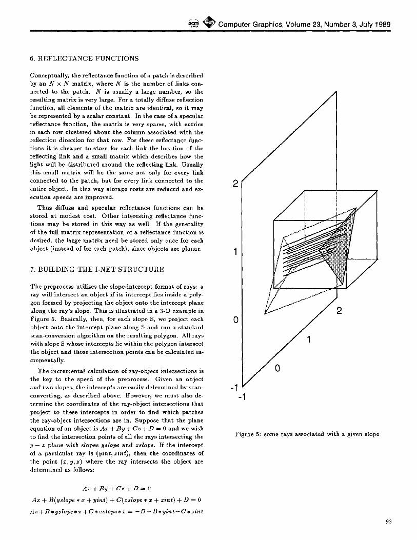
The preprocess uti l izes the s lope- in tercept format of rays: a ray will in tersect an ob jec t if i ts in tercept lles inside a poly- gon formed by pro jec t ing the objec t onto the in tercept plane along the ray ' s slope. This is i l lus t ra ted in a 3-D example in F igure 5. Basically, then, for each slope S, we pro jec t each object onto the in te rcept p lane along S and run a s t andard scan-conversion a lgor i thm on the resul t ing polygon. All rays wi th slope S whose in tercepts lie within the polygon intersect the object and those intersect ion poin ts can be ca lcula ted in- cremental ly.
The incrementa l ca lcula t ion of ray-ob jec t intersections is the key to the speed of the preprocess. Given an objec t and two slopes, the in tercepts are easily de te rmined by scan- converting, as descr ibed above. However, we must also de- te rmine the coordina tes of the ray-ob jec t intersect ions tha t pro jec t to these in tercepts in order to find which patches the ray-ob jec t intersect ions are in. Suppose tha t the plane equat ion of an objec t is A x + B y + C z + D = 0 and we wish to find the in tersect ion points of all the rays intersect ing the y - z plane with slopes yslope and zslope. If the in tercept of a pa r t i cu la r ray is (yint , z in t ) , then the coordina tes of the point (x, y, z) where the ray intersects the object are de te rmined as follows:
A x + B y + C z + D = 0
Ax + B(ys lope • x + yint) + C(zs lope • x + z in t ) + D = 0
A x + B , y s lope , x + C • zslope* x = - D - B , y i n t - C , z in t
2
0
-1
2
0
-1
Figure 5: some rays associa ted with a given slope
93

,, S GGRAPH '89, Boston, 31 July-4 August, 1989
Figure 6: a ray and the links it generates
( - D - B * y i n t - C * z i n t ) X ~
( A + B * ys lope + C * z s lope)
This is the result for the x-coordinate; y and z are deter- mined from x. If the denomina tor is zero, then the y - and z - s l o p e s are both parallel to the object ' s plane, and if there is a solution, it will not be unique.
This calculat ion is not at all fast, and it may be made faster by noticing tha t the denomina tor need be calculated
only once for each pair of slopes. It is then combined with the numera tor coefficients so tha t
D ' = D / ( A + B • ys lope + C • z s lope)
B ' = B / ( A -F B * ys lope + C * z s lope)
C ' = C / ( A + B * ys lope + C * z s lope)
The calculat ion is now x = - D ~ - B ~ • y i n t - C p • z i n t
which is certainly faster, bu t if we take advantage of the fact tha t we are using a scan-conversion algori thm to determine
y i n t and z i n t , it may be made faster yet. Since z i n t remains constant throughout each scan and at each step of the scan conversion y i n t is incremented by 2xy, then x0 = - D t -
B ~ * y i n t - C ~ * z i n t at the s tar t of the scan, and xi+a = xi -- B I * Ay thereafter. Also, B I * Ay is fixed throughout
the scan conversion, so each step costs only an addition. The other two coordinates are de termined as before.
These intersect ion points are stored unti l all intersections have been found for S. At this point each ray with slope S
is examined for intersections; links are set up between any pair of patches which have consecutive intersections on the
ray and which face each other, as shown in Figure 6. Note
tha t many links may be set up for a single ray if there are
mult iple pairs of objects facing each other along the ray.
The regulari ty of the geometry of the patches and links
can cause noticeable aliasing. To a t t enua te the effects of this problem the ray-object intersection points are j i t te red by a random fraction of the intercept interval amount . This
procedure results in a small pe r tu rba t ion in the slope rep- resented by each link. This loss of regulari ty is achieved
very cheaply, and the resul tant noise reduces the effect of the aliasing artifacts. The general problem of aliasing due to uniform point sampling and methods of dealing with it are discussed in [9].
8. THE DISTRIBUTION PROCESS
This part of the algori thm dis t r ibutes the light throughout the scene unt i l convergence is achieved. Light is first "shot" from the light sources, which have patches and links llke any other objects. This light is sent into the scene via the light sources' links, and is accumulated in the recipient patches' in-buffers. Following the light sources' depletion, each patch in the scene is sequential ly examined for any unprocessed
light in the patch 's in-buffers. If any is found, the contents of each of the patch 's in-buffers is run through the reflectance funct ion and the result is sent outward over the patch 's links into other patches' in-buffers. This process is continued unti l no patch 's in-buffer contains an amoun t of light larger than a given small threshold value.
The reflectance funct ion calculat ions consume most of the t ime used in this process. In the general case, the reflectance
funct ion mult ipl ies the array of in-buffers by a mat r ix of co- efficients and the result is mapped back out to the array of links. As ment ioned above, we may short-circuit this proce- dure in the case of diffuse or specular reflectance functions (or a funct ion which is a combinat ion of the two) with a resul tant memory savings. For example, if a surface reflects 6 0 ~ of incoming light in a t ight specular pa t t e rn and 40~ in a diffuse pat tern , then 40~ of the incoming light will be summed into a global buffer and d is t r ibuted evenly while the
remainder will be dis t r ibuted around the reflected direction according to a small mat r ix which describes how the light spreads around the reflected direction. When the patch is
total ly diffuse only the global buffer need be mainta ined, and incoming light is processed very rapidly.
9. RENDERING
The algori thm is view-independent; no eyerays need be cal- culated prior to rendering. Given the s tandard viewing pa-
rameters, eyerays are shot from the eyepoint through each pixel of the image plane. Each eyeray is matched to the
"closest" l ink (in terms of slope and intercept) , and the eye- ray's intersection point with the nearest object (found with
a s tandard Z-buffer algori thm) determines the patch it hits.
The amount of light tha t the pixel sees is given by the to-
tal amount of light reflected from tha t patch over tha t link,
which has been accumulated in an out-buffer associated with
the link.
This procedure is not sufficient to produce good results, however. Sudden jumps in in tens i ty may occur as the eyer-
94

~ Computer Graphics, Volume 23, Number 3, July 1989
a
""q j
C
Figure 7: non-diffuse rendering
ays move from patch to patch, or the slope tha t the eyeray
is coerced to changes. To avoid these problems, the light assigned to an eyeray is interpolated in two different ways: the light intensi t ies associated with the rays surrounding the
eyeray are in terpola ted for patches in the intersected patch 's
8-neighborhood, and then these values are themselves inter- polated. This process is i l lustrated in Figure 7. A given ey- eray is associated with the four slopes that surround i t - the x - z slopes immediate ly to the left and right of the eyeray's x - z slope, and the x -- y slopes immediate ly above and
below the eyeray's x - y slope-these are called the bounding slopes. The out-buffers associated with these four slopes are evaluated for each of the patches in the intersected patch 's 8-neighborhood. For each of the four patches in each %or- net" of the 8-neighborhood, the value associated with the eyeray's slope is biliuearly interpolated from the values of the bounding slopes (a). These four result ing amounts are averaged to get a value for the center of the corner areas (b). This procedure results in four values, one at each corner of
the intersected patch. The value for the intersection point is then bil inearly interpolated from these four corner points
(c). A great deal of memory may be saved at the cost of view
independence if viewing parameters are determined dur- ing the preprocess and out-buffers allocated for only those patches and links tha t are actual ly utilized in rendering. For the special case of total ly diffuse surfaces, all the out-buffers for a given patch will contain the same value. In this case more memory may be saved by subs t i tu t ing a global out- buffer for each patch, and t ime may be saved by skipping
the first in terpolat ion step.
10. A N A L Y S I S O F R E S U L T S
The algori thm was implemented in C on a single processor of an Ardent T i t a n and on an HP9000 series 300. All t ime
figures are given for the Ardent; the HP workstation figures
were about 5 t imes slower. Times were measured using the gprof ut i l i ty in UNIX. All images are 500x500 pixels.
Figure 8 demonstrates the diffuse reflection performance of the algorithm. The light sources are red, green and blue vertical rectangles, which are reflected by a totally diffuse floor. Figure 9 shows the same scene with a specular floor. The irregularities of the reflections are the result of the slight
j i t t e r ing of the ray-object intersections, while the spread of the reflections is a function of the degree of specularity of the floor.
Figures 10 and 11 show the obligatory office scene. This scene was rendered at low resolution, with 2834 patches and
1201 links at each patch. 1.8 million ray-object intersections were calculated in the preprocess, which required 98 seconds for each image. Light sources are the pole lamps, the sky-
light, the monitor screen, and the t iny lights on the fronts of the machines.
In Figure 10, all the surfaces are diffuse. Memory for the I-net was 15 Mbytes. The dis t r ibut ion process required 24 seconds, and init ial ization, eyeray calculation, and ren- dering took 44 seconds. Note the light reflecting from the
desk diffusing onto the wall at low center and onto the chair pedestal. The green from the carpet also diffuses onto the lower wall.
In Figure 11, the carpet has been given a heavy coat of wax. The I-net took 18.5 Mbytes. The dis t r ibut ion process jumped to 97 seconds. Ini t ial izat ion, eyeray calculation, and
rendering took 69 seconds due to the addi t ional t ime needed for the non-diffuse rendering. Note the reflections from the light areas of the back wall on the floor foreground and the reflections from the side of the desk on the floor background. The desk front also reflects on the floor, and on the far left the light wall reflects in the floor.
11. EVALUATION OF THE ALGORITHM
While we have only tested diffuse and specular reflectance functions, the method may be used for less ordinary re- flectance functions; one example is the reflectance function of an anisotropic surface [7]. Another example is very care- ful t r ea tment of reflection where different wavelength bands reflect in slightly different directions. This would be im- plemented with a different reflectance matr ix for each color channel.
The method will also handle t ransparent objects with no modification: instead of a reflectance function, the object 's mat r ix will represent its refractance function. Translucent
objects such as frosted glass may be modeled by j i t ter ing the outgoing light direction from the incoming direction by an amount determined by the degree of translucence.
This algorithm may be used on other than planar ob- jects with no loss of speed in the dis t r ibut ion process, since
the geometry of the scene has been buil t into the I-net at
95

" \ ~ S I G G RAPH '89, Boston, 31 July-4 August, 1989
Figure 8: diffuse test scene
Figure 10: diffuse office scene
Figure 9: specular test scene
that point. The preprocess depends on the incremental cal- culat ion of ray-object intersections for much of its speed, however, and unless an efficient method of calculat ing these intersections is found the advantages of precomput ing the I-net may be lost.
One very nice feature of the algori thm is tha t the t ime and space it requires are determined primari ly by the sur- face area of all the objects in the scene and by the desired resolution, not the number of objects in the scene. The
t ime required for the preprocess is mainly a funct ion of the number of ray-object intersect ions to be calculated, and the
t ime required for the d is t r ibut ion process usually depends
pr imari ly on the number of patches. There are pathologi- cal counterexamples to this general izat ion-for instance, two mirrors facing each other will result in a very long t ime for the dis t r ibut ion process-but for most scenes it holds true.
Figure 11: "waxed carpet" office scene

~ Computer Graphics, Volume 23, Number 3, July 1989
12. F U T U R E W O R K
Al though this technique correct ly models bo th diffuse and non-diffuse interref lect ions in a scene (to some degree of res- olution), often the pa tch size may be large enough tha t ex- t remely specular reflections look poor to the eye. F igure 9 shows this well; the floor is a lmost a mirror , yet the pa tch size is large enough tha t "holes" appea r near the edge of the reflections where ad jacent patches reflect significantly dif- ferent amounts of l ight due to discret izat ion. This p roblem may be fixed in the current imp lemen ta t ion by reducing the pa tch size down to sub-pixel resolution, an expensive solu- t ion if the scene has much surface area.
A be t t e r approach might be to allow different patch sizes and link densit ies in different par t s of the scene. Very small or highly specular objec ts will be more accura te ly rendered if they have been divided into smal ler patches, whereas very small patches might result in much unnecessary computa- t ion in the case of, for example, a large s t re tch of b lank wall. Sharp shadow boundar ies also may require smal ler patches. Ob jec t size ~nd specular i ty are known a t preprocess t ime, and objects with app rop r i a t e characteristics may be divided into more patches than they would otherwise. Shadows can be de tec ted by not icing when two ad jacent l inks associa ted with a l igh t -emi t t ing pa tch are connected to different ob- jects; in this case more l inks are needed between the two original links.
Another solut ion is to use ray t racing for the rendering stage of the a lgor i thm. Eyerays are cast into the I-net, and unless the ray hi ts a specular object , the in tens i ty at the ray- patch in tersect ion is evaluated using bi l inear in te rpola t ion of the intensi t ies of the pa tch and i ts neighbors. If an eyeray hits a specular object , a reflected ray is cast, and a final in tensi ty calcula t ion for t ha t ray per formed unless i t hi ts a specular surface. This process continues unti l the reflected ray hi ts a diffuse object , a l ight source, is reflected out of the scene, or a threshold is reached.
Of course, if the environment is comple te ly specular, this process degenerates into s t anda rd ray tracing, and the I-net is redundant . W h a t separa tes this from [1] and two-pass methods ([12]) is t ha t all the i l lumina t ion of the environ- ment, including both diffuse and nondiffuse interreflection, has been comple ted at the rendering stage, and the ray trac- ing merely provides some addi t iona l resolut ion where i t mat - ters most. In fact, one can consider this technique to be a form of d i s t r ibu ted raytracing, wi th the I-nets providing a fast way of evaluat ing the non-specular rays. Since most of the rays will be eyerays whose intersect ions must be calcu- la ted in any case, this procedure will result in l i t t le addi- t ional work if much of the scene is diffuse.
Since the geomet ry of a scene is bui l t into a da t a s t ructure, an in teres t ing extension of this work involves animat ion. If for each l ink an accumula to r keeps a to ta l of the amount of l ight t ha t has passed over the l ink (out-buffers corresponding to the in-buffers ment ioned previously) then we can save
informat ion between frames. When an object moves between two frames, we de te rmine the links tha t are affected and negate the l ight tha t has t raveled over the links; tha t is, l ight tha t previously t raveled over the l inks will be negated and sent down the same links. This "negat ive l ight" will be run through the reflectance functions a t each patch, and the resul t ing (smaller) amounts of negat ive l ight are d ispatched onto the links. This process continues unti l convergence.
At this point the scene is exact ly as i t would have looked had the affected links never been there. The l inks are then removed and new links are es tabl ished which reflect the ge- omet ry of the upda t e d scene. The same light tha t was negated is now released down these new links and d i s t r ibu ted until convergence and the scene is rendered. Note tha t if the vast ma jo r i ty of the links were unaffected by the change, most of the work done for the first f rame will have been saved.
Another area for explora t ion is the para l le l iza t ion poten- t ia l of this a lgori thm. In the preprocess, the incrementa l ray- object in tersect ion calculat ions are bo th s lope- independent and objec t - independent ; s lope-objec t pairs may be taken from a queue by idle processors. In the d is t r ibu t ion process, each pa tch can have i ts own processor which per iodical ly ex- amines the pa tch ' s in-buffers and processes any light i t finds there and sends the resul ts out over the pa tch ' s links.
Hardware ass is tance may be useful for the scan-conversion por t ion of the preprocessing s tep and the rendering, in the manner of [4].
A C K N O W L E D G M E N T S
Our thanks to Emi l ia Vil larreal , A.T. Campbel l , and K.R. Subraman lan for many helpful technical discussions and sug- gestions. We would also like to thank the folks at the Univer- sity of Texas Sys tem Center for High Performance Comput - ing, in par t icu la r Jesse Driver and Dan Reynolds, for their assis tance and the use of their machines.
R E F E R E N C E S
[1] Arvo, James, Backward Ray Tracing, Developments in Ray Tracing ( S I G G R A P H '86 Course Notes), Vol. 12, Augus t 1986.
[2] Arvo, James and David Kirk, Fas t Ray Tracing by Ray Classification, Computer Graphics ( S I G G R A P H '87 Proceedings) , Vol. 21, No. 4, Ju ly 1987, pp. 55-64.
[3] Cohen, Michael F., Donald P. Greenberg, A Radios i ty Solut ion for Complex Environments , Computer Graph- ics ( S I G G R A P H '85 Proceedings) , Vol. 19, No. 3, July
1985, pp. 31-40.
[4] Cohen, Michael F., Shenchang Chen, John Wallace, Donald P. Greenberg, A Progressive Refinement Ap- proach to Fast Radios i ty Image Genera t ion , Computer
97

~ ~ S I G G RAPH
Graphics (SIGGRAPH '88 Proceedings), Vol. 22, No. 4, August 1988, pp. 75-84.
[5] Cook, Robert L., Thomas Porter, Loren Carpenter, Distributed Ray Tracing, Computer Graphics (SIG- GRAPH '85 Proceedings), Vol. 19, No. 3, July 1985, pp. 111-120.
[6] Immel, David S., Michael F. Cohen, Donald P. Green- berg, A Radiosity Method for Non-Diffuse Environ- ments, Computer Graphics (SIGGRAPH '86 Proceed- ings), Vol. 20, No. 4, August 1986, pp. 133-142.
[7] Kajiya, James T., Anisotropic Reflection Models, Com- puter Graphics (SIGGRAPH '85 Proceedings), Vol. 19, No. 3, July 1985, pp. 15-21.
[8] Kajiya, James T., The Rendering Equation, Computer Graphics (SIGGRAPtt '86 Proceedings), Vol. 20, No. 4, August 1986, pp. 143-150.
[9] Mitchell, Don P., Generating Antialiased Images at Low Sampling Densities, Computer Graphics (SIGGRAPtt '87 Proceedings), Vol. 21, No. 4, July 1987, pp. 65-72.
[10] Nashita, Tomoyuki and Eihachiro Nakamae, Continu- ous Tone Representation of Three-Dimensional Objects Taking Account of Shadows and Interreflection, Com- puter Graphics (SIGGRAPH 85 Proceedings), Vol. 19, No. 3, July 1985, pp. 22-30.
[11] Ohta, Masataka and Mamoru Maekawa, Ray Coherence Theorem and Constant Time Ray Tracing Algorithm, Computer Graphics t987 (Proceedings of CG Interna- tional '87), ed. T. L. Kunii, pp. 303-314.
[12] Wallace, John R., Michael F. Cohen, Donald P. Green- berg, A Two-pass Solution to the Rendering Equa- tion: A Synthesis of Ray Tracing and Radiosity Meth- ods, Computer Graphics (SIGGRAPH '87 Proceed- ings), Vol. 21, No. 4, July 1987, pp. 311-320.
[13] Ward, Gregory J., Frances M. Rubinstein, Robert D. Clear, A Ray Tracing Solution for Diffuse Interreflec- tion, Computer Graphics (SIGGRAPH '88 Proceed- ings), Vol. 22, No. 4, August 1988, pp. 85-92.
[14] Whitted, Turner, Art Improved Illumination Model for Shaded Display, Communications of the ACM, Vol. 23, No. 6, June 1980, pp. 343-349.
'89, Boston, 31 July-4 August, 1989
98


![Realistic modeling and rendering of plant ecosystems · Realistic modeling and rendering of plant ecosystems ... CR categories: I.3.7 [Computer Graphics]: Three-Dimensional ... To](https://static.fdocuments.us/doc/165x107/5b3fdc017f8b9aff118c9e2f/realistic-modeling-and-rendering-of-plant-ecosystems-realistic-modeling-and.jpg)