Illumination Models & Surface-Rendering Methods
42
1 Computer Graphics
-
Upload
gouravsoni -
Category
Documents
-
view
38 -
download
2
description
illumination model
Transcript of Illumination Models & Surface-Rendering Methods

1
Computer Graphics
2
Chapter 14
Illumination Models & Surface-Rendering Methods
Computer Graphics
3
Illumination Models & Surface-Rendering Methods
• Illumination model or a lighting model is the model for calculating light intensity at a single surface point.
• Surface rendering is a procedure for applying a lighting model to obtain pixel intensities for all the projected surface positions in a scene.

4
Surface rendering
• Surface rendering can be performed by applying the illumination model to every visible surface point, or the rendering can be accomplished by interpolating intensities across the surface from a small set of illumination-model calculations.
• Scan-line algorithms use interpolation schemes.• Ray tracing algorithms invoke the illumination
model at each pixel position.• Surface-rendering procedures are termed surface-
shading methods.
5
Illumination models
Given the parameters: • the optical properties of surfaces
(opaque/transparent, shiny/dull, surface-texture);• the relative positions of the surfaces in a scene;• the color and positions of the light sources;• the position and orientation of the viewing plane.Illumination models calculate the intensity projected
from a particular surface point in a specified viewing direction.

6
Lecture Plane
• Light Sources
• Basic Illumination Models
Ambient Light
Diffuse Reflection
Specular Reflection & Phong Model
Combine Diffuse & Specular Reflections with Multiple Light Sources

7
Light Sources
• When we view an opaque nonluminous object, we see reflected light from the surfaces of the object.
• The total reflected light is the sum of the contributions from light sources and other reflecting surfaces in the scene.
• Light sources = light-emitting sources.• Reflecting surfaces = light-reflecting sources.

8
Light Sources
LightSource
ReflectingSurfaces
Fig. 1Light viewed from an opaque surface is in general a combination of reflected light from a light source and reflections of light reflections from
other surfaces.

9
Point Light Source• The rays emitted from a point
light radially diverge from the
source.• Approximation for sources
that are small compared to
the size of objects in the scene.• A point light source is a fair approximation to a
local light source such as a light bulb. • The direction of the light to each point on a
surface changes when a point light source is used.
Fig. 2Diverging ray paths from a point light source.

10
Distributed Light Source • A nearby source, such as
the long fluoresent light.• All of the rays from a
directional/distributed
light source have the
same direction, and no
point of origin. • It is as if the light source was infinitely far away
from the surface that it is illuminating. • Sunlight is an example of an infinite light source.
Fig. 3An object illuminated with a distributed light source.

11
Materials
• When light is incident on an opaque surface, part of it is reflected and part is absorbed.
• Shiny materials reflect more of the incident light, and dull surface absorb more of the incident light.
• For an illuminated transparent surface, some of the incident light will be reflected and some will be transmitted through the material.

12
Diffuse reflection • Grainy surfaces scatter the reflected light in all
directions. This scattered light is called diffuse reflection.
• The surface appears equally bright from all viewing directions.
• What we call the color of an object is the color of the diffuse reflection of the incident light.
Fig. 4Diffuse reflection from a surface.
13
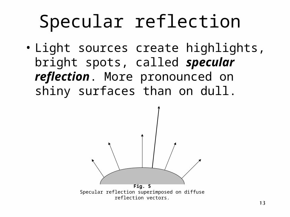
Specular reflection
• Light sources create highlights, bright spots, called specular reflection. More pronounced on shiny surfaces than on dull.
Fig. 5Specular reflection superimposed on diffuse reflection vectors.
14
Basic Illumination ModelsLighting calculations are based on:• Optical properties of surfaces, such as
glossy, matte, opaque, and transparent. This controls the amount of reflection and absorption of incident light.
• The background lighting conditions.• The light-source specifications. All light
sources are considered to be point sources, specified with a coordinate position and intensity value (color).
15
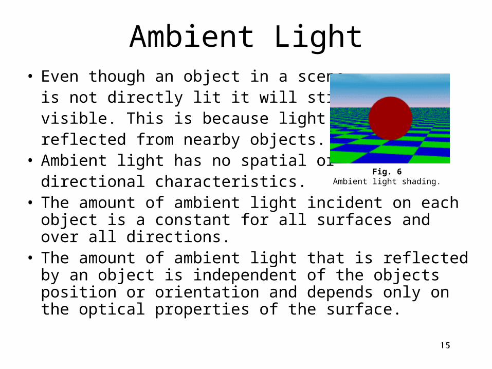
Ambient Light• Even though an object in a scene
is not directly lit it will still be visible. This is because light is reflected from nearby objects.
• Ambient light has no spatial or directional characteristics.
• The amount of ambient light incident on each object is a constant for all surfaces and over all directions.
• The amount of ambient light that is reflected by an object is independent of the objects position or orientation and depends only on the optical properties of the surface.
Fig. 6Ambient light shading.
16
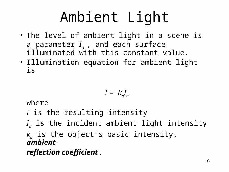
Ambient Light• The level of ambient light in a scene is a
parameter Ia , and each surface illuminated with
this constant value. • Illumination equation for ambient light is
I = kaIa
whereI is the resulting intensity
Ia is the incident ambient light intensity
ka is the object’s basic intensity, ambient-reflection coefficient.
17
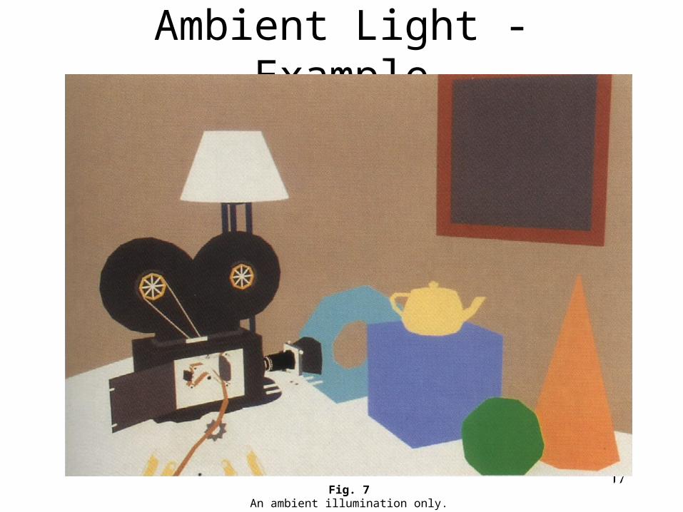
Ambient Light - Example
Fig. 7An ambient illumination only.
18
Diffuse Reflection
• Diffuse reflections are constant over each surface in a scene, independent of the viewing direction.
• The amount of the incident light that is diffusely reflected can be set for each surface with parameter kd, the diffuse-reflection coefficient, or diffuse
reflectivity.
0 kd 1;
kd near 1 – highly reflective surface;
kd near 0 – surface that absorbs most of the
incident light;
kd is a function of surface color;

19
Diffuse Reflection Even though there is equal light scattering in all directionfrom a surface, the brightness of the surface does dependon the orientation of the surface relative to the lightsource:
(a) (b)
Fig. 8A surface perpendicular to the direction of the incident light (a) is more illuminated than an equal-sized surface at an
oblique angle (b) to the incoming light direction.

20
Diffuse Reflection• As the angle between the surface normal
and the incoming light direction increases, les of the incident light falls on the surface.
• We denote the angle of incidence between the incoming light direction and the surface normal as . Thus, the amount of illumination depends on cos. If the incoming light from the source is perpendicular to the surface at a particular point, that point is fully illuminated.

21
Diffuse ReflectionIf Il is the intensity of the point Light source, then the diffuse reflection equation for a point on the surface can be written as
Il,diff = kdIlcosor
Il,diff = kdIl(N.L)
where N is the unit normal vector to a surface and L is theunit direction vector to the point light source from aposition on the surface.
Fig. 9Angle of incidence between the unit light-source direction vector L and the unit surface normal N.
N
L
To Light Source

22
Diffuse Reflection
Figure 10 illustrates the illumination with
diffuse reflection, using various values of
parameter kd between 0 and1.
Fig. 10Series of pictures of sphere illuminated by diffuse reflection model only using different kd values (0.4, 0.55, 0.7, 0.85,1.0).
23
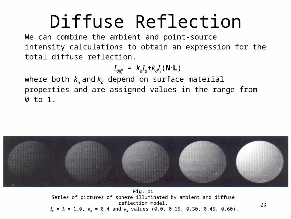
Diffuse ReflectionWe can combine the ambient and point-sourceintensity calculations to obtain an expression for thetotal diffuse reflection.
Idiff = kaIa+kdIl(N.L)
where both ka and kd depend on surface material
properties and are assigned values in the range from0 to 1.
Fig. 11Series of pictures of sphere illuminated by ambient and diffuse reflection model.
Ia = Il = 1.0, kd = 0.4 and ka values (0.0, 0.15, 0.30, 0.45, 0.60).
24
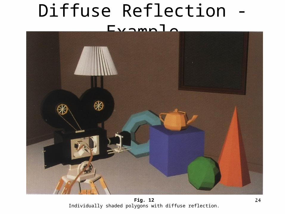
Diffuse Reflection - Example
Fig. 12Individually shaded polygons with diffuse reflection.
25
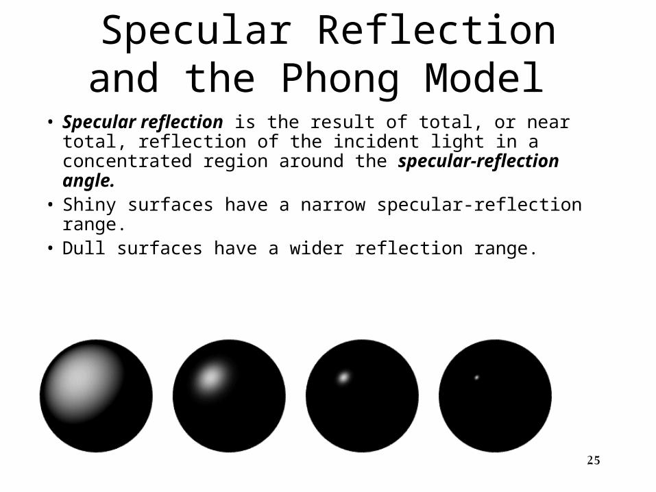
Specular Reflection and the Phong Model
• Specular reflection is the result of total, or near total, reflection of the incident light in a concentrated region around the specular-reflection angle.
• Shiny surfaces have a narrow specular-reflection range.• Dull surfaces have a wider reflection range.
26
Specular Reflection
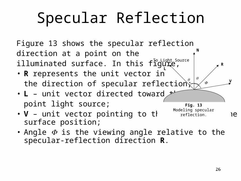
Figure 13 shows the specular reflection direction at a point on the illuminated surface. In this figure, • R represents the unit vector in
the direction of specular reflection;• L – unit vector directed toward the
point light source;• V – unit vector pointing to the viewer from the surface position;• Angle is the viewing angle relative to the specular-reflection
direction R.
Fig. 13Modeling specular reflection.
N
L
To Light Source
R
V
27
Phong Model
Phong model is an empirical model for calculating the
specular-reflection range:• Sets the intensity of specular reflection proportional to
cosns;• Angle assigned values in the range 0o to 90o, so that
cos values from 0 to 1;
• Specular-reflection parameter ns is determined by the
type of surface,
• Specular-reflection coefficient ks equal to some value
in the range 0 to 1 for each surface.

28
Phong Model
• Very shiny surface is modeled with a large value for ns
(say, 100 or more);• Small values are used for duller surfaces.
• For perfect reflector (perfect mirror), ns is infinite;N
L
R
Shiny Surface (Large ns)
N
L
R
Dull Surface(Small ns)
Fig. 14Modeling specular reflection with parameter ns.

29
Phong Model cosns
Fig. 15Plots of cosns for several values of specular parameter ns.
30
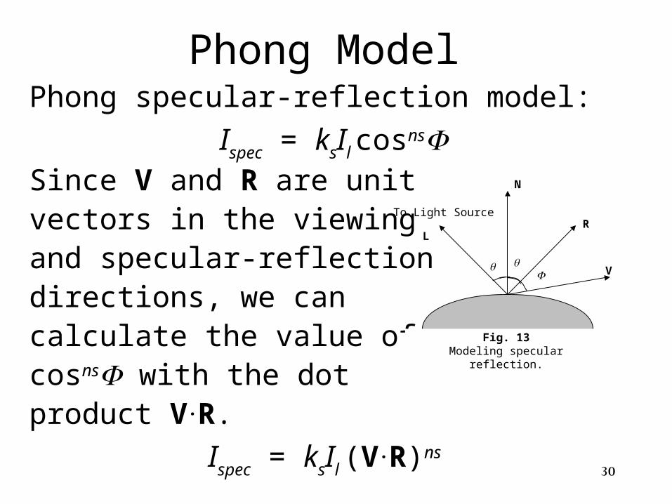
Phong Model Phong specular-reflection model:
Ispec = ksIl cosnsSince V and R are unit vectors in the viewing and specular-reflectiondirections, we can calculate the value of cosns with the dot product V.R.
Ispec = ksIl (V.R)ns
Fig. 13Modeling specular reflection.
N
L
To Light Source
R
V

31
Phong Model
R + L = (2N.L)N
R = (2N.L)N-L
N
LR
N.L
L
Fig. 16Calculation of vector R by considering projections onto the direction of the normal vector N.
32
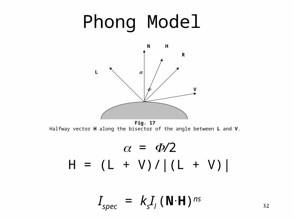
Phong Model N
L
R
V
Fig. 17Halfway vector H along the bisector of the angle between L and V.
H
= /2H = (L + V)/|(L + V)|
Ispec = ksIl (N.H)ns

33
Specular Reflection - Example
Fig. 18Phong shading polygons with specular reflection.

34
Combine Diffuse & Specular Reflections
For a single point light source, we can model
the combined diffuse and specular reflections
from a point on an illuminated surface as
I = Idiff + Ispec
= kaIa + kdIl(N.L) + ksIl(N
.H)ns
35
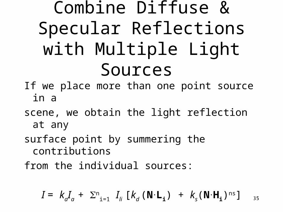
Combine Diffuse & Specular Reflections with Multiple Light
Sources
If we place more than one point source in a
scene, we obtain the light reflection at any
surface point by summering the contributions
from the individual sources:
I = kaIa + ni=1 Ili [kd (N
.Li) + ks(N.Hi)
ns]
36
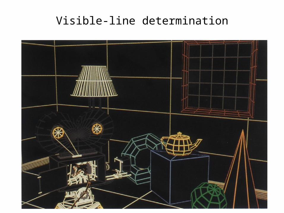
Visible-line determination

37
Visible-surface determination with ambient illumination only

38
Individually shaded polygons with diffuse reflection

39
Gouraud shaded polygons with diffuse reflection
40
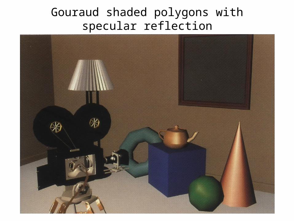
Gouraud shaded polygons with specular reflection

41
Phong shaded polygons with specular reflection
42
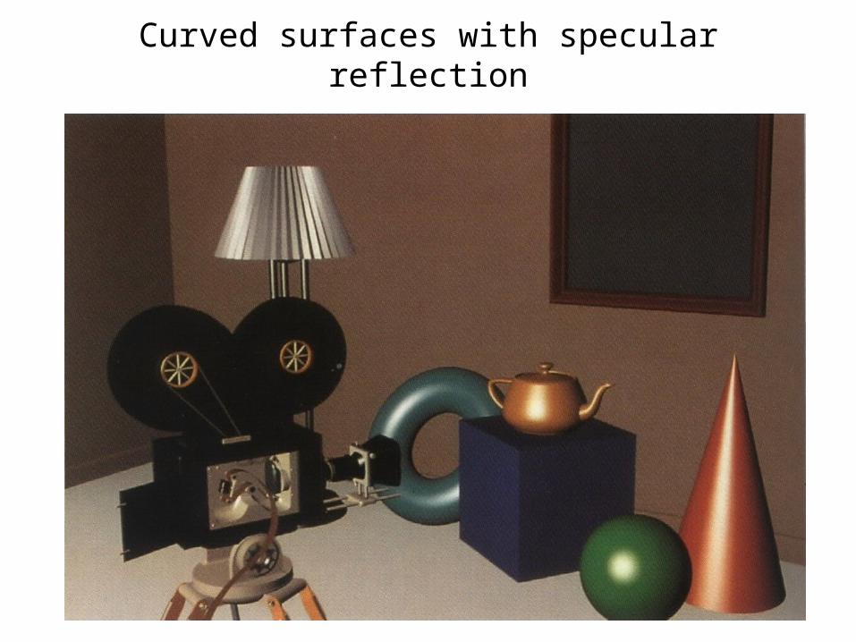
Curved surfaces with specular reflection