ILER-DDS - Radio · ILER-DDS VFO/DDS de 0 a 40MHz Page 3 INTRODUCTION The ILER-DDS VFO is a...
22
ILER-DDS VFO/DDS de 0 a 40MHz Page 1 ILER-DDS Universal VFO/DDS 0 to 40 MHz Assembly manual Last review: March 01, 2013 Translated by Jon EA2SN [email protected] Latest updates and news: www.qsl.net/ea3gcy Thanks for purchasing the “ILER-DDS” 0 to 40 MHz VFO kit. Enjoy building QRP ! 73 Javier Solans, ea3gcy
Transcript of ILER-DDS - Radio · ILER-DDS VFO/DDS de 0 a 40MHz Page 3 INTRODUCTION The ILER-DDS VFO is a...

ILER-DDS VFO/DDS de 0 a 40MHz Page 1
ILER-DDS
Universal VFO/DDS 0 to 40 MHz
Assembly manual
Last review: March 01, 2013 Translated by Jon EA2SN
Latest updates and news: www.qsl.net/ea3gcy
Thanks for purchasing the “ILER-DDS” 0 to 40 MHz VFO kit.
Enjoy building QRP ! 73 Javier Solans, ea3gcy

ILER-DDS VFO/DDS de 0 a 40MHz Page 2
TABLE OF CONTENTS
TOC…............………………………………………………………………………………………. 2
INTRODUCTION……………………………………………………………………………………. 3
SPECIFICATIONS.….………………..…………………………………………………………….. 3
PART ONE: ASSEMBLY AND INSTALLATION……………………………………………….. 4
TIPS FOR FIRST TIME BUILDERS………………………………………....……………………. 4
PARTS LIST..………………..………………………………………………………..…………….. 6
ASSEMBLY..…………………….………………………………………………………………….. 7
INSTALLATION…………..……………….…..……………………………………....................... 8
DIGITAL NOISE………………….…………..………………………………………………......... 12
ILER-DDS WIRING………...……………………………………………………………………... 13
SCHEMATICS……………………………………………………………..…………………….... 13
PART TWO: PROGRAMMING AND USING THE VFO/DDS ..….....…………………….... 14
FACTORY CONFIGURATION……………….……………………………………………...…. 14
USING THE ILER-DDS……………...…………….……………………………………………… 15
USER MENUS………….………….…………….…………………………………..…………… 15
MENU FLOWCHART………………..…….……………………………………………….…… 16
CONFIGURATION………………..……………….……………………………………………… 16
IF YOUR KIT DOES NOT WORK AFTER FINAL ASSEMBLY …………………..………… 20
LIMITED WARRANTY ………………………..….……………………………………………… 20
OUTPUT SIGNAL IMAGES…………..…….…………………………………………………… 21

ILER-DDS VFO/DDS de 0 a 40MHz Page 3
INTRODUCTION
The ILER-DDS VFO is a universal, 0 to 40 MHz RF generator based on the Analog Devices AD9850
DDS chip (www.analog.com). At present, the direct digital synthesis (DDS) is an excellent solution for the
LO on monoband and multiband amateur equipment, at a very moderate cost. Due to the very high
frequency reference (125 MHz), the ILER-DDS offers a very clean signal when working at relatively low
frequencies as 11, 20 or even 30 MHz. (< 25% of the reference frequency). If you want to delve deeper
into the theory of DDS we advice you to read the abundant internet literature. The use of a "sandwich"
single block mechanical configuration and a single encoder with a built-in push-button to control the
operation makes this VFO/DDS an extremely versatile "block" easy to integrate in many projects for
amateur rigs.
SPECIFICATIONS
Universal VFO for all ILER transceivers and similar projects.
RF Generator: from 0 to 40 MHz.
Configurable Tuning Steps: selected ones or all steps (from 10 Hz to 10 MHz).
Programmable IF Offset from 0 to 40 MHZ. IF=RF+VFO, IF=RF-VFO, IF=VFO-RF, IF = 0 (RF generator).
Programmable upper and lower band limit.
Fine calibration of the frequency reference by software (up to 1 Hz accuracy).
Voltmeter display with 0.1 V resolution (0.01 V calibration).
Possibility of auxiliary analog inputs (for future expansion).
Auxiliary I/O pins for expansion.
SINUSOIDAL OUTPUT (NO SQUARE WAVE).
LOW SPURIOUS. TX and RX mixers spectrum is equal to or better than a VXO one.
DDS AD9850BRS integrated circuit.
Reference clock: 125 MHz.
Output signal: 300-500 mVpp @200 Ω.
User programmable “Welcome message”: callsign or name.
LOCK function for push button and encoder.
Automatic record of last used frequency or current frequency.
2 Line x 8 character LCD with AUTO-ON-OFF configurable backlight.
Power supply: 9-14 V about 140 mA.
Outboard encoder for a more versatile mechanical configuration.
Small size "sandwich" module, easy to fix with screws or glue.
Total space used: 51 x 36 x 40 mm W-H-L (with soldered LCD 35 mm L). LCD window size 29 x 19 mm.
Soft touch non-stop rotary encoder (like commercial equipment).
24 steps per revolution rotation encoder (maximum speed 36 step/s).
All operations are executed with the encoder and pushbutton.
Simple, direct, and immediate configuration through menus.
All settings are stored in EEPROM (1 million write/read cycles (minimum) and 100-year).
PIC18F2525-I/SP microcontroller 20 MHz clock.
Connections for firmware update (ICSP).
Complete kit for an easy construction: all parts, encoder and 3 PCB included (SMD already soldered).

ILER-DDS VFO/DDS de 0 a 40MHz Page 4
PART ONE:
ASSEMBLY AND INSTALLATION
PLEASE READ THOROUGHLY ALL THE MANUAL AT
LEAST ONCE BEFORE ANY WORK IS DONE.
TIPS FOR FIRST TIME BUILDERS
Tools required:
- Small tipped soldering iron of about 25-30 W rating, small side cutters, wire strippers, pliers, long nosed
pliers, sharp hobby knife, and screw driver for the M3 bolt.
- You will also need good lighting and a magnifying glass to read the fine print on some parts.
Instrumentation required:
- Multimeter. Frequency Counter or calibrated HF receiver.
Soldering:
There are two important things which need to be done to ensure the successful operation of a kit: one is
to put the right part into the proper place on the board; the other is good soldering.
To properly solder you must use the correct type of iron and the right quality of solder. Use a small tipped
soldering iron whose bit is short and pointed at the end. The iron should be about 25-30 W (if it is not
thermostatically controlled). Only use multicored solder for electronics. NEVER use any extra flux. You
should hold the hot iron in contact with both the board and the part lead for about two seconds to heat
them up. Then, keeping the iron in place, touch the solder onto the junction of lead and track and wait
about two seconds or so until the solder flows along the lead and track to form a good joint. Now remove
the iron. The iron should have been in contact with the part and circuit track for a total time of about 4
seconds. It is a good idea to drag the tip of the iron up the component lead as you remove it from the
joint, this helps to pull any excess solder up with it and enables good flow along the component lead.

ILER-DDS VFO/DDS de 0 a 40MHz Page 5
Finding the right part:
IC’s
The board outline for ICs has a “U” notch on one end. This indicates the pin 1 end of the IC. There is
also a notch on one end of the sockets. This end goes over the “U” notch outline on the board. ICs have
usually pin 1 marked with a round dimple or dot. This end of IC will go towards the notch on the socket or
“U” on the outline.
Electrolytic capacitors:
These must be installed with the correct polarity. The positive (+) lead is always the long lead. The
negative (-) lead is marked by a stripe on the body of the capacitor can. Make sure the plus end of the
cap goes toward the hole labeled with the (+).

ILER-DDS VFO/DDS de 0 a 40MHz Page 6
PARTS LIST
Resistors Checked Ref. Value Ident./Comment Circuit section
R1 10K brown-black-orange MCLR uC pin
R2 10K brown-black-orange ADC divider
R3 4K7 yellow-violet-red ADC divider
R4 -- See Table 1 Contrast (1)
R5 -- See Table 1 Backlight limiter (1)
Rx-Ry 0 1/16W 0ohm. Factory soldered PCB links
Capacitors
Checked Ref. Value Ident./Comment Circuit section
C1 100n 104 or 0.1 Power
C2 10uF 10uf 25V or 35V (elec) Power
C3 100n 104 or 0.1 Power
C4 18p SMD Factory soldered Uc
C5 18p SMD Factory soldered uC
C6 100n 104 or 0.1 uC
C7 100n 104 or 0.1 uC
100n 100n 104 or 0.1 On encoder terminals
100n 100n 104 or 0.1 On encoder terminals
Semiconductors, Crystal, Inductor, Encoder, Modules
Checked Ref. Value Ident./Comment Circuit section
IC1 7805 7805 5V regulator Regulator
IC2 18F2525-I/SP Microcontroller Controller
X1 20MHz. 20MHz cristal uC clock
L1 100uH SMD Factory soldered uC +V
Encoder Bourns Encoder PEC16 Rotary Encoder/Switch Encoder/Switch
LCD 8x2 LCD 8x2 LCD Display 8x2 (backlight) Display
AD9850 AD9850 HC-SR08 DDS module DDS
Hardware
Checked Ref. Value/Type Ident./Comment Circuit section
IC2 socket 28 pins IC socket uC
Pins strip Pins for connections -- Connections
Pin strip sockets Cut with various measures. -- Connections
Heatsink for IC2 Heatsink for IC2 -- Heatsink
M3x10 screw Screw for IC1 heatsink -- Heatsink
M3 nut M3 nut for M3x10 screw -- Heatsink
Table 1. R4 and R5 values
Your kit may have three types of similar LCD.
R5 and R5 are different depending on the type of LCD. All resistors are included in the kit, but only need to be used
according to the following table:
LCD Type R4 (Contrast) R5 (Backlight)
GREEN 0802A (Ver1.0) 3K3 orange-orange-red 10 Ω brown-black-black
BLUE RT0802A 4K7 yellow-violet-red 47 Ω yellow-violet-black
BLUE LCM0802C (V1.0) from 1K2 (brown-red-red) to 2K2 (red-red-red) 47 Ω yellow-violet-black
You can vary slightly the R4 and R5 values.
< R4 (less): increases contrast (you can use an 5K adjustable resistor to find the best value).
< R5 (less): increases backlight (R5 can never be 0 Ω).
ILER-DDS VFO/DDS de 0 a 40MHz Page 7
ASSEMBLY
As many modern kits, the ILER-DDS is designed to be easily assembled by medium-experience
builders. SMD components are already installed and there are no hard-to-install parts on the kit.
It is advisable that you inventory all parts to make sure everything is available and ready for assembly.
Each builder may have his/her own way of organizing parts, but if you do not, you might try using a block
of Styrofoam packing material. Parts may be sorted by type and size (ohms, microfarads etc).

ILER-DDS VFO/DDS de 0 a 40MHz Page 8
RECOMMENDED ASSEMBLY SEQUENCE
I strongly recommend that you install the parts in the following order:
1. Resistors. All resistors are placed vertically.
2. Capacitors. C2 is an electrolytic capacitor, the longer terminal is positive. There is a "+" printed on
the PCB.
3. Crystal. Open its legs carefully and insert it into the PCB.
4. IC socket for IC2. Note that the "u" mark on one end must match that marked on the board
silkscreen. Ensure that it lies flat on the board.
5. Male and female terminal strips. Ensure that they are straight and flat to the PCB. There are four
female socket strips (two of 8 pin to hold the LCD, and two of 10 pin to hold the DDS module),
and four male terminal strips (two of 8 pin to be soldered to the LCD, and for the control board
one of 5 pins A-E, and another one of 12 pins 1-12).
6. Voltage regulator. Place the 7805 regulator IC with its lettering facing the board. Place the small
heatsink included with the kit, with the "U" facing outwards (see the cover photo).
7. IC2. Insert the PIC18F2525-I/SP microcontroller into its socket..
8. LCD and DDS module. Insert the LCD and AD9850 DDS module into their respective sockets.
INSTALLATION
PIN FUNCTION
Marking Function uC bit
1 +12V +12V
2 GND GND
3 ENCODER_A RB5
4 ENCODER_B RB4
5 PULSADOR RB3
6 AUX RB2
7 AUX RB1
8 AUX RB0
9 AUX RA4
10 AUX RA5
11 GND GND
12 SIGNAL OUT (sine wave) OUT
A AUX/ICSP (in circuit serial programming) RB6
B AUX/ICSP (in circuit serial programming) RB7
C GND GND
D +5V +5V
E MCLR MCLR
ILER-DDS VFO/DDS de 0 a 40MHz Page 9
Mechanical Installation
Important: Do not rush to make the mechanical installation. It is highly recommended that you
calmly study every possible way to place the DDS assembly block in your rig.
There are some wiring requirements that should be taken into consideration (see "ILER-DDS
Wiring"). Take care when planning the configuration most suitable for your application.
As you can see, the ILER-DDS block is designed to be easily incorporated into any existing rig, being
receivers, transceivers or as a general purpose laboratory RF generator.
Without doubt, there are many ways of implementing the integration of the ILER-DDS on your project.
Mechanically, there are two ways to attach the ILER-DDS block: with screws or with glue. I recommend
using "contact adhesive" on the LCD frame and the box front panel. A thin "line" of glue around the LCD
frame is sufficient. This is an extremely simple and safe method, and provides very good aesthetic
results. If necessary, you can always remove the LCD and clean the glue residue.
Do not use hard to remove adhesives such as cyanoacrylate, epoxy, etc.
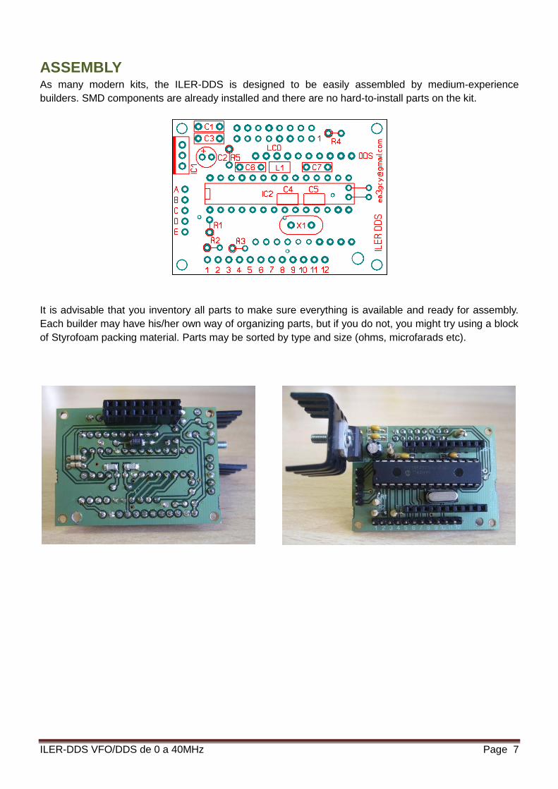
In the pictures below, you can see a DDS block installation next to an ILER transceiver. The DDS is
attached with glue. As the LCD is fixed to the panel the other two modules (control board and AD9850
module) can be unplugged when required.
If the space available for the module integration is a bit short the depth of the
sandwich may be reduced by 5-7 mm by directly soldering the LCD to the board,
instead of using male and female headers. Please notice that if board removal is
needed in the future, you will have to unsolder all pins from the LCD or the board.
Note: The routing and placing of the ILER-DDS wiring may change the "digital noise" perceived (see
"Digital Noise"). For instance, sometimes the use of metallic screws to hold the LCD on the panel may
increase the noise, in lieu of a decrease, as one may think. A similar situation occurs with the supply
negative wire; the connection may be done through the shield of the coaxial cable. If noise is
objectionable you will have to proceed with a trial and error denoising process (see "ILER-DDS wiring").

ILER-DDS VFO/DDS de 0 a 40MHz Page 10
Using the ILER-DDS on ILER transceivers
The new ILER boards (from 2013 January), marked “0113” on the underside, do not require any
modification; you will only have to disconnect L7.
For previous versions, a simple mod is required to connect the ILER-DDS to your transceiver.
1) You will have to cut or lift one leg of L7 to remove the supply to the VXO. It is not required to remove
any part from the VXO!
2) Cut the track going from C50 to the emmiter of Q4 and place a bridge upwards to the R32-R33
junction pads (boards marked 0113 do not need this change).

ILER-DDS VFO/DDS de 0 a 40MHz Page 11
It is possible to use either the VXO or the DDS?
May I work SOTA or backpack with the VXO and with the DDS at home?
Of course you do! You may have both and select one as needed.
This is probably the only amateur transceiver which may be configured to work this way. Slick!
With its low power VXO it will be possible to operate on the field or up the summits with a small battery
on your backpack. And with the DDS and its backlighted LCD display, a bit higher on consumption, you
will be able to operate on your car or at home.
It is simple:
Build your ILER complete, including the VXO and adjust it as per
the manual. You will have to place the ILER on a box with a dual
tuning system: the Polyvaricon for the VXO and the encoder for
the DDS.
Then, a DPDT switch must be used to route the supply for the DDS
on one of the circuits, and to connect L7 with the pad where it was
connected previously (VXO supply).

ILER-DDS VFO/DDS de 0 a 40MHz Page 12
DIGITAL NOISE
Noise coming from digital circuits on a radio receptor may be considered as normal when they are of low
level and the listening comfort and quality is not affected.
There are two types of noise: DDS generated spurs and noise from the digital control and display.
The design used on the ILER-DDS guarantees a low spur level when compared with other amateur
products of similar price. In all ILER versions the heterodyne purity is very high either in Rx or Tx. Due to
the filtering used little spurs are generated which may be noticed in reception, and also in transmission.
All tests carried out with our ILER-DDS prototypes with ILER transceivers have been highly
satisfactory.
LCD noise
LCDs are known to be a source of noise. Sometimes one may thing the noises are coming from the RF
generator but they are coming from the display. They may be recognized as they shift in frequency,
especially after a cold start-up. Should you perceive a background noise on your transceiver without any
antenna connected, and the noise changes when you touch or push the LCD, this is an LCD noise.
Encoder noise and other switching/digital noises.
The second, very common source of internal noises on a receiver is the switching of internal signals,
multiplexing, etc, or external signals, such as the ones from the encoder.
When you install the encoder, please remember to place a pair of 100 nF capacitors on the encoder
terminals.
If you do a careful and tidy wiring of the ILER-DDS, we are sure that you will get excellent results.
Note:
EA3GCY can not guarantee the result of fitting an ILER-DDS with receiver or transmitter kits others than
the ones from ea3gcy. The different combination of IF-RF, signal levels, impedances, etc. may led to
unpredictable results. You should know the details of your particular setup and enough expertise to
evaluate the suitability of the ILER-DDS for your purposes.

ILER-DDS VFO/DDS de 0 a 40MHz Page 13
ILER-DDS WIRING
The wiring is very simple but is important how you do it.
We don't want it to just work...... it should work PERFECTLY!
The position and wiring of the ILER-DDS will strongly affect the reception of noises in the receiver (see
"Digital noises").
Some advices to be taken into account:
For the output signal use good quality, fine coaxial cable (ej. RG-174). A very long coax, or a low
quality one may led to the appareance or increase of digital noises.
Place the encoder as close as possible to the ILER-DDS block. If it is far away, and wires go by
or over the transceiver circuit may introduce switching noises whenever the encoder is used.
Even the supply wires to the connector or the ON-OFF switch may affect the nose level. Try with
only one wire, the positive one, as the negative will be routed through the coax shield.
It is not advisable to wire the LCD. The LCD should be sandwiched with the control board!
By the way: Do not forget to place two 100 nF capacitors directly between the encoder pins!
If need be, you will have to make changes on the wire routing or the wire type; it will be a "trial and error"
procedure.
Sometimes low level noises detected may disappear when the antenna is connected, and do not
affect adversely the reception. In that case: you don't have to fight them!
By following the previous advices, the wiring of the ILER-DDS is very simple. Please check the drawing:
The wiring described is from the back of both the encoder and the control board.
Your ILER-DDS kit can incorporate two types of rotary encoder. The two models are the same but have
their terminals positioned differently. Type A has the encoder terminals on top and the "push-switch" are
below. The type B has all the above, the encoder terminals are shorter and the switch are longer.

ILER-DDS VFO/DDS de 0 a 40MHz Page 14
Please notice that none of the two models the "common" terminal is central. It is to the right.
Solder two 100 nF capacitors directly to the encoder pins
(between active pins and ground).
SCHEMATICS

ILER-DDS VFO/DDS de 0 a 40MHz Page 15
PART TWO:
PROGRAMMING AND USING THE
VFO/DDS
FACTORY CONFIGURATION
The ILER-DDS is configurated to work with the ILER-40, with the following parameters:
LOWER LIMIT: 07.000 (Band lower limit: 7.000 MHz).
UPPER LIMIT: 07.300 (Band upper limit: 7.300 MHz).
YOUR CALL ?: CALL ON: EA3GCY
OFFSET: not used
IF FREQ: IF = 04913500 Mode: VFO = RF + FI
IF is 4.913500 MHz and the output mode from the VFO/DDS is 7.000000 MHz + 4.913500 MHz
Please notice that the IF relal offset is lower than the nominal frequency of the IF filter crystals (4.915.8 MHz).
CAL FREQ: +0 Hz (you will have to adjust it to compensate for tolerances)
CAL VOLT: Calibrated. The measuring error may be up to +/-10 %
You will have to adjust it, as each kit may be different due to the resistors used at the divider placed at the input of
the ADC conversor (R2 and R3)
LOCK: Unlock
SAVE FREC INI: Save final (it will save the last frequency used)
LCD BACKLIGHT: ON (always lit)
CHANGE STEPS: 1 kHz - 100 Hz.
USING THE ILER-DDS
It is very simple. Once programmed, its use is highly intuitive.
Dial tuning and step change:
By turning right or left the rotary encoder the frequency respectively
increases or decreases by the current "step".
This is marked by an underline on the digit. For instance, the example
shows the underline digit as the kHz units. Every step will move the frequency one kHz up or down. If the
underline will be placed on the 100 Hz digit, the steps will be of 100 Hz each.
A quick push on the encoder will change the position of the underline among the preselected "CHANGE
STEPS”.
User Menus
You may access the menus by pushing and holding the encoder pushbutton for more than 1 second.
Then, turning the encoder will go through the user menus. One of the options is “EXIT” to exit without
change. Please consult the cyclic sequence of the menu flowchart on next page.
The access to the more frequently used functions is easy.
7 1 5 0 . 0 0
1 2 . 5 V

ILER-DDS VFO/DDS de 0 a 40MHz Page 16
10 kHz steps:
This may be used to move rapidly throughout the band. Push the encoder
for more than 1 second. “10 kHz STEP” will appear on the screen. A quick
push on the encoder will bring you back to the frequency dial with 10 kHz
steps. Once you are on the place of the dial you want, another quick push will bring you back to the
normal tuning steps.
Lock:
This function allows an easy and fast lock or unlock procedure for the dial
when you are working on a fixed frequency. Push the encoder for more than
1 second, turn the encoder until LOCK appears on the screen and make a
quick push. LCD will turn off and the encoder will remain inactive. To recover push the encoder for more
than 1 second.
Save Freq Ini:
This menu option allows you to select the initial frequency of the ILER-DDS
at power-up. Push the encoder for more than 1 second, turn the encoder
until “SAVE FREQ INI” appears and make a quick push. By turning the
encoder you will see “SAVE CURRENT” (to store the current frequency as the power-up frequency) or
“SAVE FINAL” (to store the last frequency used prior to power-down). A quick push will confirm the new
setting and send you back to the normal frequency dial.
Change Steps:
There are four fixed sequences of steps available for selection:
1K-100H-20H ; 1K-100H ; 100H-20H ; ALL STEPS
Push the encoder for more than 1 second, turn the encoder until “CHANGE
STEPS” appears and make a quick push. By turning the encoder you will enter a submenu to select with
the encoder the step sequence needed. A quick push on the encoder will bring you back with the new
sequence active.
Note: The “ALL STEPS” option is meant to be used when the ILER-DDS is used as RF generator.
Lcd Backlight:
The LCD backlight mode of operation may be selected with this menu entry.
Push the encoder for more than 1 second, turn the encoder until “LCD
BACK LIGHT” appears and make a quick push. By turning the encoder you
will cycle between “AUTO” (backlight will automagically turn off after 10 seconds of encoder or
pushbutton inactivity), “ON” (LCD always lit) or “OFF” (LCD always off). A quick push on the encoder will
bring you back with the new backlight option to the frequency dial.
Exit:
This menu entry allows you to go back to the frequency dial without
changes. You only need to make a quick push on the encoder.
1 0 k H z
S T E P
L O C K
. . . . . . . .
S A V E
F R E Q I N I
C H A N G E
S T E P S
L C D B A C K
L I G H T
E X I T
. . . . . . . .

ILER-DDS VFO/DDS de 0 a 40MHz Page 17
MENU FLOWCHART
CONFIGURATION In principle the ILER-DDS may seem very complicated, but it is not.
Prior to making any changes in the configuration you will have to study your project needs. Once you
know exactly what do you want and how to do it: configuration will be easy, simple and fun!
To activate the configuration menu you will have to power on the ILER-DDS while you keep
pushed the encoder. (pushbutton + power-on).
On screen you will see the first entry of the configuration menu, and turning the encoder will cycle
through all the options. One of them is “EXIT”, which will allow you to go back and start up the ILER-DDS
normally without making any changes.
Lower Limit:
One of the entries is “LOWER LIMIT”. This is used to set the band lower
limit. Make a quick push, then you will have the option of entering any
frequency in the range 0 to 40 MHz in 50 kHz steps.
This is usually the lower limit of the amateur band the receiver or transceiver
is prepared for, but it may be placed at whatever frequency you like, even
out of band. Once the frequency is set, make a quick push and the ILER-
DDS will start-up normally.
Note: If you plan to use the ILER-DDS as RF generator you may adjust the limits to the ones you like for
your generator, even 0 and 40 MHz!
L O W E R
L I M I T
0 7 . 0 0 0
< L I M I T

ILER-DDS VFO/DDS de 0 a 40MHz Page 18
Upper Limit:
Keep turning the encoder until you see “UPPER LIMIT” when you want to
set the band upper limit. Make a quick push, then you will have the option of
entering any frequency in the range 0 to 40 MHz in 50 kHz steps.
This is usually the upper limit of the amateur band the receiver or
transceiver is prepared for, but it may be placed at whatever frequency you
like, even out of band. Once the frequency is set, make a quick push and
the ILER-DDS will start-up normally.
Your Call ?:
Keep turning the encoder until you see “YOUR CALL ?” and make a quick
push. You will program a welcome message at turn-on, typically your
amateur radio callsign.
With a quick push you will cycle between “CALL ON” and “CALL OFF”.
“CALL OFF” may be selected with a quick push when you do not want any
welcome message.
Should you want to program a message, go to “CALL ON” and make a quick
push. Now you will se the last programmed word (i.e. EA3GCY). You may
enter up to 8 characters on the top line. The underline shows the position to be programmed. Turn the
encoder to cycle between letters, numbers and symbols for each position. Once you are happy with the
character selected make a quick push: the character will get stored and the cursor will move to the next
position. Complete all 8 positions. One of the available characters is an empty space which may be also
used. You will have to go through all 8 positions, even if they are blank spaces to complete the process.
After the 8th position is programmed, a quick push will complete the process and the ILER-DDS will
start-up normally.
Take your time, as there is no "back-space". If you make a mistake you will have to repeat the process
since the beginnin.
IF Freq:
Keep turning the encoder until you see “IF FREQ” and make a quick push.
This entry will be used to set the IF frequency.
Frequency is adjusted by the Hz, so all 8 positions are operative: for
instance an IF of 35 MHz must be programmed as 35000000 whereas 9
MHz will be 09000000. The underlined cursor shows the position of the digit
to be programmed. Turn the encoder to select the desired digit at the
position and make a quick push to store the value and move to the next position. When you will get to
the 8th position, the next push will store the last digit and the ILER-DDS will jump with to a second
submenu where the IF Mode will be selected. There is no "back-space". If you make a mistake you will
have to repeat the process since the beginning.
The submenu for IF mode will cycle when the encoder is turned among the following options:
VFO = IF + RF ; VFO = IF - RF ; VFO = RF - IF ; IF = 0 (this will be used for an RF generator) ; EXIT
To select one of the options make a quick push when the screen shows the one you want. The ILER-
DDS will restart normally with the new setting. If you don't want to change the program you may use the
“EXIT” entry.
U P P E R
L I M I T
0 7 . 3 0 0
> L I M I T
Y O U R
C A L L ?
C A L L
O N
E A 3 G C Y
F I
F R E Q
0 4 9 1 3 5 0 0

ILER-DDS VFO/DDS de 0 a 40MHz Page 19
These are the nominal IF configurations for the ILER-40 and ILER-20 transceivers:
BAND (RF) LOWER LIMIT UPPER LIMIT IF FREQ IF MODE VFO/DDS OUT
ILER-40 7.000 7.300 4.915 VFO = IF + RF 11.915 - 12.215
ILER-20 14.000 14.350 3.276 VFO = RF - IF 10.724 - 11.074
Some configuration examples for typical bands and IF values:
BAND (RF) LOWER LIMIT UPPER LIMIT IF FREQ IF MODE VFO/DDS OUT
3.500 3.500 3.800 9.000 VFO = IF + RF 12.500 - 12.800
7.000 7.000 7.300 9.000 VFO = IF - RF 2.000 - 1.700*
28.000 27.000 30.000 10.700 VFO = RF - IF 16.300 - 19.300
RF GEN 0 40.000 -- IF=0 0 to 40 MHz
*Notice that on this mode (VFO = IF - RF) when the RF frequency increases, the VFO/DDS generated
frequency should decrease, and vice versa.
Cal Freq:
Keep turning the encoder until you see "CAL FREQ" and make a quick
push. On this entry it is possible to make a fine adjustment of the frequency
of the DDS in order to compensate for tolerances on the reference oscillator
or the IF parts, which may be of the order of several hundred Hz. The adjustment margin goes from -
2500 Hz to +2500 Hz. (If this margin is not enough, it may be a sign that the
programmed IF value is incorrect).
IMPORTANT: To "calibrate" the frequency of the dial, never adjust the BFO of the transceiver.
This is not the way to do it! Do not run the BFO adjustment, which has no relation whatsoever
with the frequency spotting of the dial and should NEVER be adjusted to compensate for the LO
(VFO) offset.
The ILER-DDS, when used as local oscillator (LO) for a receiver o transceiver, will be generating a
frequency which is the sum of the frequency that you may read on the LCD top line (it is the frequency
stored at the menu entry "Save Freq Ini") plus or minus the IF value, stored on the menu entry IF FREQ
(VFO=IF+RF, VFO=IF-RF o VFO=RF-IF).
When the ILER-DDS is used as RF generator (IF FREQ mode will be IF = 0) the generated frequency
will be the one shown on the display.
I will show several ways of doing this adjustment.
If you use the ILER-DDS as LO:
- Should you have access to a good frequency counter and you trust its calibration, or a good receiver
with enough dial resolution, you may check the theoretical frequency based on the display number and
the IF offset and mode. This method, though, will not allow you to compensate the frequency error
caused by the IF tolerances.
- If you are using the ILER-DDS for an SSB transceiver and you have access to a good receiver, tune it
to the frequency shown on the display and check your transmission on the receiver while you speak.
Adjust the calibration value, as it if were a Clarifier, until you get a perfect tuning and your voice sound
natural.
C A L
F R E Q
0 7 1 5 0 0 0 0
+ 0 H z

ILER-DDS VFO/DDS de 0 a 40MHz Page 20
- A third option, similar to the previous one, is to do the adjustment "on the air" while listening to a station
of known frequency, tweaking the calibration until you get a perfect tuning.
If you are using the ILER-DDS as RF generator:
- Should you have access to a good frequency counter and you trust its calibration, just read the
frequency generated by the DDS and tweak the calibration until the counter reading and the LCD dial
match.
- In case you don't have a counter, you may use a good receiver.
Once you are done, make a quick push to exit. The adjustment will get stored and the ILER-DDS will
restart up normally.
Notes:
-This is a very precise adjustment, with a resolution of one Hz. If you listen on a receiver the tone change
is very slow. Please be patient to obtain a good calibration.
-Should you are going to use a receiver for the adjustment, you should be really sure of the dial precision
(do not use medium quality scanners or receivers with unknown precision).
Cal Volt:
Keep turning the encoder until you see “CAL VOLT” and make a quick push.
You will be adjusting the analog/digital conversion. You will have to know the
exact voltage of your power supply or battery. By turning the encoder you
will move the displayed value to the supply voltage. Use a good quality
multimeter for this measurement. After the adjustment a quick push will exit
from the configuration menu and the ILER-DDS will start-up normally.
C A L
V O L T
1 3 . 5 5
V O L T

ILER-DDS VFO/DDS de 0 a 40MHz Page 21
IF YOUR KIT DOES NOT WORK AFTER FINAL ASSEMBLY
Do not worry, it is quite normal that a kit does not work right away. Take your time, as most of the cases
are small errors easy to fix.
Many errors are due to poor soldering or wrongly placed parts. The failure of one of the supplied parts is
very rare. Prior to taking any measurements at the board, have a good look, check all connections,
inspect the board for parts not soldered, solder bridges between tracks, sockets with bad contacts or
wrongly placed parts.
If the kit does not work as expected, follow these steps, in this order:
-Check every step of the assembly manual, the soldering work and the installed parts.
-If you have access to instrumentation, take measures and follow the circuit signals to diagnose what is
happening and why.
-Talk with an expert ham or technician and ask him or her to check your work. A pair of fresh eyes may
see something you haven't noticed.
-If you think it is needed, I will entertain any request for technical assistance to [email protected]. If
need be, you may send your kit in, but I will have to charge you for the repair work done: I will try to
make these charges as reduced as possible.
LIMITED WARRANTY
Please read carefully PRIOR to do any work with your kit.
All parts provided with this kit are guaranteed against any fabrication defect for one year after the sale.
The buyer has the option to examine the kit and the instruction manual for 10 days. If during this period
he or she decided not to build the kit, it will be possible to send the kit back, with all shipping charges
payed by the customer. The seller shipping charges and all other costs involved (Ebay or Paypal
charges) will not be reimbursed.
If you plan to ship it back, PLEASE CONSULT how to do it to [email protected]
Javier Solans, ea3gcy, guarantees that when the kit is built and adjusted following the information
enclosed in this manual, and it is used according to the advices mentioned, it will work according to its
specifications.
It is your duty to follow the advices and recommendations of this manual, correctly identify the parts, use
good working procedures and have access and correctly use the tools and instruments requirede for the
assembly and adjustment of the kit.
In case you think any part for the kit is missing, please make an inventory of all parts with the parts list
included on the manual. Please revise all bags, envelopes or boxes carefully. If something is missing,
please send me an email and I will mail you the part right away. Even if you don't want to bother with a
common part you may have on your junk-box or a local store, please let me know so I can help other
customers with a similar problem.
I can also provide a part that you have broken, dammaged or lost by accident.
In case you find any errata or mistake on this manual, or you like to make a comment, please get in
touch with me at [email protected]
Enjoy building QRP!
73 Javier Solans, ea3gcy
ILER-DDS VFO/DDS de 0 a 40MHz Page 22
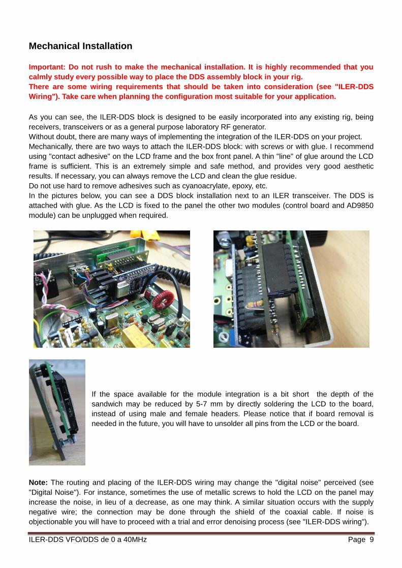
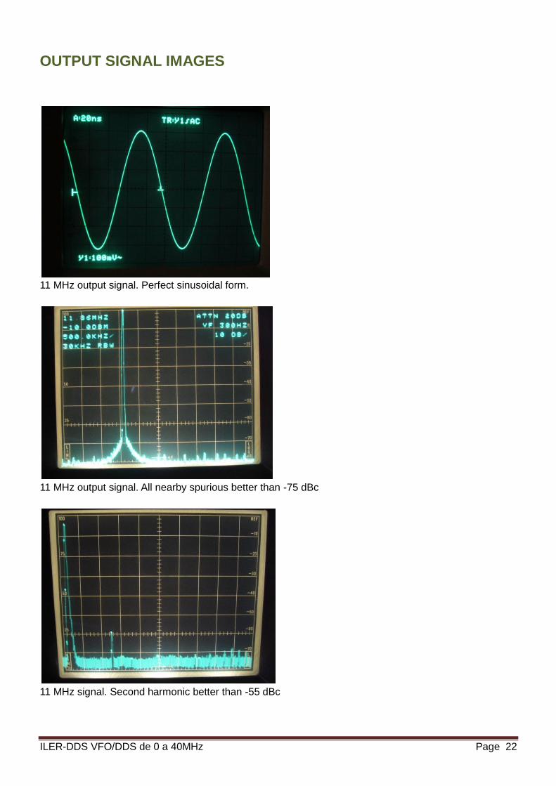
OUTPUT SIGNAL IMAGES
11 MHz output signal. Perfect sinusoidal form.
11 MHz output signal. All nearby spurious better than -75 dBc
11 MHz signal. Second harmonic better than -55 dBc