Software description of SDR-X V 3 - I0CG · The SDR-x software can be used on several Ham...
20
1 Software description of SDR-X V 3.8 1 Preliminary Simplified description .............................................................................................. 2 1.1 Power-on set-up to enable or disable of SW functions ....................................................... 4 1.1.1 Functions enabled at power-up when the VFO Key has pressed:............................... 4 1.1.2 Functions enabled with power-up when the RIT Key has pressed: ............................. 5 1.1.3 Functions enabled with power-up when the Band- UP Key has pressed: ................... 5 1.1.4 SIDE-TONE setup enabled with power-up when Band-dw pressed ........................... 5 1.2 Operation.............................................................................................................................. 6 1.2.1 FUNTION MODE Key ( <FUN> ) ............................................................................ 6 1.2.2 INCREMENT / DECREMENT Key (VAL) ............................................................... 7 1.2.3 VFO Key selection ...................................................................................................... 7 1.2.4 RIT key ........................................................................................................................ 7 1.2.5 Band Down and UP (BAND DN UP) .......................................................................... 7 1.2.6 Use of PC Keyboard .................................................................................................... 7 1.3 Hardware interface ............................................................................................................. 10 1.3.1 I/O used in the PIC master ......................................................................................... 11 1.3.2 Connection of a PC Keyboard ................................................................................... 11 1.3.3 Connection of optical encoder ................................................................................... 12 1.3.4 Interconnections of PIC controller to DDS ................................................................ 12 1.3.5 Cabling PTT to the MASTER PIC ........................................................................... 13 1.3.6 Expansion PIC connections ....................................................................................... 14 1.3.7 Expansion PIC connections to drive USB and LSB quartz of product detector ....... 15 1.3.8 Expansion PIC connections to drive USB and LSB and CW quartz ........................ 16 1.4 My homebrew projects using this software ....................................................................... 17
-
Upload
nguyenthuy -
Category
Documents
-
view
217 -
download
0
Transcript of Software description of SDR-X V 3 - I0CG · The SDR-x software can be used on several Ham...
1
Software description of SDR-X V 3.8
1 Preliminary Simplified description ..............................................................................................2
1.1 Power-on set-up to enable or disable of SW functions.......................................................4 1.1.1 Functions enabled at power-up when the VFO Key has pressed:...............................4 1.1.2 Functions enabled with power-up when the RIT Key has pressed:.............................5 1.1.3 Functions enabled with power-up when the Band- UP Key has pressed: ...................5 1.1.4 SIDE-TONE setup enabled with power-up when Band-dw pressed ...........................5
1.2 Operation..............................................................................................................................6 1.2.1 FUNTION MODE Key ( <FUN> ) ............................................................................6 1.2.2 INCREMENT / DECREMENT Key (VAL) ...............................................................7 1.2.3 VFO Key selection......................................................................................................7 1.2.4 RIT key ........................................................................................................................7 1.2.5 Band Down and UP (BAND DN UP)..........................................................................7 1.2.6 Use of PC Keyboard ....................................................................................................7
1.3 Hardware interface.............................................................................................................10 1.3.1 I/O used in the PIC master .........................................................................................11 1.3.2 Connection of a PC Keyboard ...................................................................................11 1.3.3 Connection of optical encoder ...................................................................................12 1.3.4 Interconnections of PIC controller to DDS................................................................12 1.3.5 Cabling PTT to the MASTER PIC ...........................................................................13 1.3.6 Expansion PIC connections .......................................................................................14 1.3.7 Expansion PIC connections to drive USB and LSB quartz of product detector.......15 1.3.8 Expansion PIC connections to drive USB and LSB and CW quartz ........................16
1.4 My homebrew projects using this software .......................................................................17

2
1 Preliminary Simplified description The SDR-x software can be used on several Ham communications projects as described in the following:
• DDS VFO application :all functions of a digital DDS VFO based on AD9951 or AD9912 ( high performance 14 bit DDS ) can be performed: this SW can driver the DDS with many features ( sum or subtraction of any IF, suggestion of the Band selector for vintage transceiver as Collins or Drake, insertions of RIT, 20 memory, scanning of memory, dual VFO ( A and B ), scanning from freq. of VFOA to freq. of VFOB, memory of last band used and so on.
• STANDARD RTX: a standard receiver or transceiver with any type of IF in the
range 0 to 80 MHz: for this applications this SW, in addition to above features, can be performed a complete control of an input RX/TX front-end, PTT, PTT timing for TX and RX, RX /TX control for BFO (IF modifications for USB, LSB and CW offset), TX Split,CW generation with standard PC keyboard, direct dialling of any freq. with standard PC keyboard. Two type of front-end can be controlled: a) with dedicated filter for each Ham band (K2 Elecraft like); in this case 9 Filter can be switched to select 9 Ham band. b) with continue tuning from 2 MHz to 30 MHz; in this case a 10 bit control (1024 tuning step) perform linear tuning of the preselector (Ciao Radio like) ( see my preselector documentations ).
• DIRECT CONVERSION RTX: a direct conversion RX or RTX: in this case, in addition to the above features, the necessary 4 x nominal freq. can be produced to allow use of I/Q DDS clock ( this clock can be produced using my programmed PLD able to generate two square output ¼ of input freq. out of phase of 90° in the range 0-50 MHZ).
This firmware will be always under development so many others functions can be available in the future. Any up-date has available for free if the old PIC is returned, or for the cost of an empty PIC if old PIC isn’t returned. Please don’t ask for source or object code; I ship only PIC with security bit ON. A second PIC microprocessor named “expansion” can be necessary for some of the above functions. For link between this two PIC device (“master PIC” and “expansion PIC”) a TTL serial connection must be used (only one wire is necessary). This SW has contained inside a Microchip Flash device PIC18F2620 ( 64 K flash memory). To perform the applications above described some others Hardware modules can be used as :
• PIC controller with 2 x 16 Chr LCD display and 8 Key keyboard • AD9951 board to generate sine from 1 to 200 MHz / or AD9912 to generate sine
from 1 to 430 MHz ( to prefer for new project, especially if SDR ) • Optional 500 MHz oscillator or optional 1GHz oscillator to be used with AD9912 • Automatic, continue tuning 1 – 30 MHz antenna preselector (PCB available )
used inside SDRx project

3
• PLD to generate 2 x I/Q carrier in the range 0 -50 MHz ( for DDS running 0-200
MHz ) • SDRx main board ( Full SDR receiver with 50 MHz input filter ) ( PCB available )
Note that programmed PIC 18F2620 must be requested for use with DDS AD9951 or AD9912 .with both DDS functions are the same; little differences are specified in this document To see documentations of some of the mentioned modules : see my web pages http://www.i0cg.com
4
Power-on set-up to enable or disable of SW functions
This software is easily configurable to adapt all RX or RTX type as described in the following
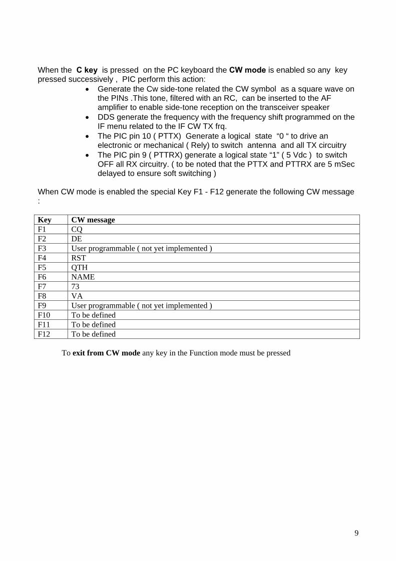
1.1.1 Functions enabled at power-up when the VFO Key has pressed: ( 8 parameter can be changed )
1. Freq. max: insert the maximum frequency used in the applications in the range 10 – 199 MHz .On AD9912 this setup is not used
2. IF offsets : to enable IF positive, negative ( freq. generated is Display +/- IF) or I/Q mode or SDr-1000 ( frequency generated is 4 x the display freq. indication ) ; to set IF frequency value see the next paragraph
3. SET DDS CLOCK: any DDS clock can be programmed in the range 1 MHz – 1000 MHz with 1 Hz resolutions ( Function Key +/- perform tuning step and Key +/- perform freq. tuning)
4. S meter On: Enable ore disable the S meter indication on the LCD display if analog s.meter present( see schematic for wiring )
5. ENC. SEN.: perform the tuning encoder sensitivity for the auto step tuning function (if value 255 auto-step tuning is off)
6. SUGGESTION : this function perform the Band suggestion for the vintage transceiver like Drake R4, Drake TR7, Drake SPR4, Collins or No suggestion
7. Function MODE menu : from 1 to 15 . Perform the # of functions in the mode menu. Normally it is not necessary to enable all functions (i.e.: if you are using a receiver, functions related to transmitter are not necessary). See table of all functions mode menu
8. CFR2 (only for AD9951): DDS register CFR2 programming. Value is 0 if the internal PLL is bypassed ( used when external oscillator as the 500 MHz osc. is used);Value of 39 is programmed if a 100 MHz oscillator is used . With 39 the x 4 multiplayer has enabled allowing the internal PLL to generate 400 MHz clock. For others multiplayer value see the AD9951 data –sheet.
9. PLL(only for AD9912): Pll On or OFF if the internal PLL is used or not. If PLL is settled to Off an external oscillator must be used ( ie. My 1 GHz external reference), if settled On see next command
10. PLL mult. (only for AD9912): set to 3 the PLL multiplier if 100 MHz reference on the DDS board is used, so Internal PLL oscillator work to 1 GHz.
To scroll and read only the programmed parameters from 1 to 8 the “Band-UP“ key must be used ( the fourth key on the right on the bottom line of key ) To store permanently parameters switch off controller and switch ON again without pressing any Key

5
1.1.2 Functions enabled with power-up when the RIT Key has pressed: This set-up is not necessary and is automatically disabled if I/Q mode for SDR type receiver is used ; IF is automatically set to 0 for I/Q mode or at 11KHz for SDR-1000 mode). With this set-up it is possible adjust 6 different IF frequency ( used in traditional IF TRX) : LSB RX LSB TX USB RX USB TX CW RX CW TX The IF frequency in TX and RX can be different allowing to use different SSB filter for TX and RX. A full- setup of all 6 parameters is only necessary if BFO is controlled via Expansion PIC ( see 1.3.2.1 ) If BFO isn’t controlled then, only first two parameter must be programmed ( Ie: 9 MHz )
1.1.3 Functions enabled with power-up when the Band- UP Key has pressed: This key perform only the central HAM band set-up to the default value stored on the PIC memory
1.1.4 SIDE-TONE setup enabled with power-up when Band-dw pressed This key the Sidetone frequency set-up ( range 300-1000 Hz ). Press Val + / - to incncrement / decrement frequency Press Band- DW to listen frequency Press Band-UP to store Side-tone frequency

6
1.2 Operation
key disposition
1.2.1 FUNTION MODE Key ( <FUN> ) The FUN key scroll UP and Down functions of the following table MODE MENU # Description VFO A=B 0 Set VFO B = VFO A VFO B=A 1 Set VFO A = VFO B Mem Read 2 Read the 20 memory bank Mem. Write 3 Write in the 20 memory bank Scan A --> B 4 Scan from frequency of VFO A to frequency of VFO B Scan memory 5 Scan from memory 1 to memory 20 Step tuning 6 Set any step value for tuning in the range 1 Hz - 1 MHz Lock 7 Lock tuning on / off Gen. Coverage
8 Skip from MHz to MHz from 1 to 30 MHz to speed general coverage reception
DDS level * 9 DDS level change: step 1 dB in the range +7 - -60 dBm for AD9951 .With AD9912 level range is +7 , -17 dBm not dB codified
Sleep 10 Sleep the CPU to reduce power consumption and RF interference ( CPU has reactivated pushing the functions mode key )
Pre/Att. 11 Turn on and off Preamplifier and Attenuator (Key- : Pre, Key+ : Att ) Used in the Automatic preselector used in the SDRx
Preselector 12 preselector tuning, if present, from 5 to 5120 step 5 pF ( 1024 values ) Used in the SDRx
CW Mode 13 TX Function: enable CW transmission with PC keyboard or standard key (to exit to this mode press the RIT key )
Split mode 14 TX Function: enable Split mode (RX on VFO A , TX on VFO B) Tx Timer 15 Enable display to indicate TX time * The DDS can be changed from +7 to -60 dBm on the AD9951 where a Register for level change is present. This is no possible with AD9912 where this register isn’t available, but using the output current register a restrict level change is possible in the range +7 -15 dBm The FUNCTION MODE Key menu must be enabled in the range 1 – 15 at power up ( see above ) Ie:

7
• for a VFO only application program to 10 • for SDR Receiver program to 12 • for Transceiver program to 15
1.2.2 INCREMENT / DECREMENT Key (VAL) The Val key increment or decrement function selected with Function mode Key
1.2.3 VFO Key selection VFO Key toggle from VFO A to VFO B
1.2.4 RIT key This key perform the Rx RIT function on and off . When RIT ON is selected the VAL key increment and decrement RIT value from + 2000 Hz to -2000 Hz with 10 Hz step
1.2.5 Band Down and UP (BAND DN UP) This two key increment or decrement ten HAM band from 1.8 MHZ to 50 MHz The last frequency used inside the ham bands are recorded in the EEPROM memory. To reset all amateur Bands to the default value turn ON with the BAND UP key pressed If the READ MEMORY or WRITE MEMORY menu are selected this two Key increment or decrement the memory instead of Band selection If Step tuning menu is selected this two key increments Frequency instead Band selection, this function can be useful if Optical encoder isn’t installed
1.2.6 Use of PC Keyboard Several operations can be done with a standard PC keyboard. The primary use to shortcut of some Function mode menu as described in the following:
1) the arrow key ↑ perform : Band-UP 2) the arrow key ↓ perform : Band-DW 3) the arrow key → perform: tuning step up ( 1Hz – 1 MHz ) 4) the arrow key ← perform : tuning step down 5) Pag. ↑ key perform: Frequency tuning up ( same use of optical encoder ) 6) Pag ↓ key perform : frequency tuning down 7) F key perform : display ask for frequency entry via numeric Key ( ie: display
ask: load frq. you press : 07 050 000 to receive at 7050 KHz 8) C key perform: enter CW mode ( see below the explanation )
8
9) When CW mode is enabled the Pag. ↑ key and Pag ↓ key perform CW speed
set-up
9
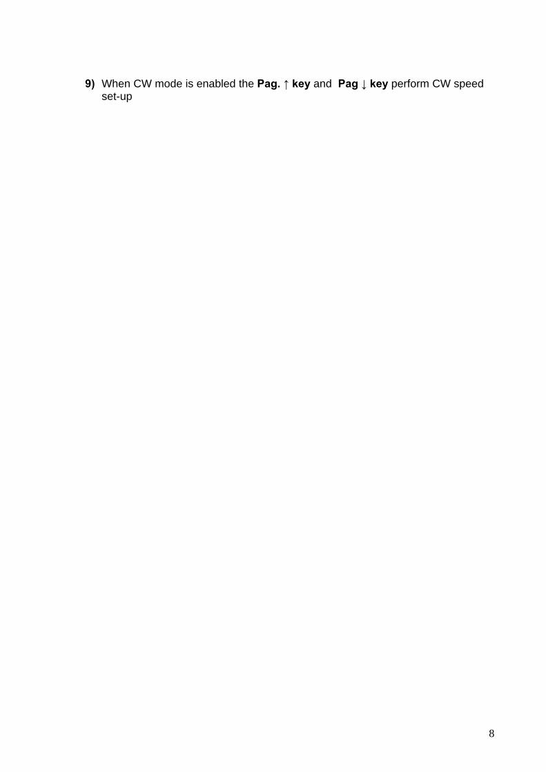
When the C key is pressed on the PC keyboard the CW mode is enabled so any key pressed successively , PIC perform this action:
• Generate the Cw side-tone related the CW symbol as a square wave on the PINs .This tone, filtered with an RC, can be inserted to the AF amplifier to enable side-tone reception on the transceiver speaker
• DDS generate the frequency with the frequency shift programmed on the IF menu related to the IF CW TX frq.
• The PIC pin 10 ( PTTX) Generate a logical state “0 “ to drive an electronic or mechanical ( Rely) to switch antenna and all TX circuitry
• The PIC pin 9 ( PTTRX) generate a logical state “1” ( 5 Vdc ) to switch OFF all RX circuitry. ( to be noted that the PTTX and PTTRX are 5 mSec delayed to ensure soft switching )
When CW mode is enabled the special Key F1 - F12 generate the following CW message : Key CW message F1 CQ F2 DE F3 User programmable ( not yet implemented ) F4 RST F5 QTH F6 NAME F7 73 F8 VA F9 User programmable ( not yet implemented ) F10 To be defined F11 To be defined F12 To be defined
To exit from CW mode any key in the Function mode must be pressed

10
1.3 Hardware interface
Some example wiring are used in my Homebrew transceiver
Block diagram of logic part of a generic transceiver using this software

11
1.3.1 I/O used in the PIC master I/O PIN PIC
Master Signal name I/O description
A0 2 VFOA – VFOB/S-meter Digital input or Analog input (shared) A1 3 Rit Digital input A2 4 Band UP Digital input A3 5 Band DOWN Digital input A4 6 KEY - Digital input A5 7 KEY + / CW keyer Digital input Key shared with keyer A6 10 PTTRX: a 32 MHz internal
osc. is used (no Quartz) Digital output: enable RX voltage
A7 9 PTTTX : a 32 MHz internal osc. is used (no Quartz)
Digital output: enable TX voltage
B0 21 DB4 LCD / data DDS Digital output shared LCD and DDS B1 22 DB5 LCD / IO update DDS Digital output shared LCD and DDS B2 23 DB6 LCD Digital output B3 24 DB7 LCD Digital output B4 25 RS LCD Digital output B5 26 FUN+ Digital input B6 27 E LCD Digital output B7 28 FUNC - / CW side tone out Digital input/output shared C0 11 AUXBUS 9600 baud Serial out :PIC master to
PIC slave data connection C1 12 Encoder ch 1 Optical or mechanical encoder con. C2 13 Encoder ch 2 Optical or mechanical encoder con. C3 14 I/O SYNC DDS Digital output C4 15 PTT IN Digital input C5 16 CLK DDS C6 17 DATA -keyboard Standard PC keyboard ( PS2 ) C7 18 CLOCK -keyboard Standard PC keyboard ( PS2)
1.3.2 Connection of a PC Keyboard Keyboard must be connected to C6 ( Pin 17 PIC) for clock and C7 (Pin 18 PIC ) for Data It is also necessary to supply 5 V to the keyboard. Is very important to insert a pull-up resistor between pin 17 and pin 20 of PIC ( remember that keyboard connector has the same numbering of PIC ) This pull-up is not necessary with new PIC controller PCB type i0cg 080108
12
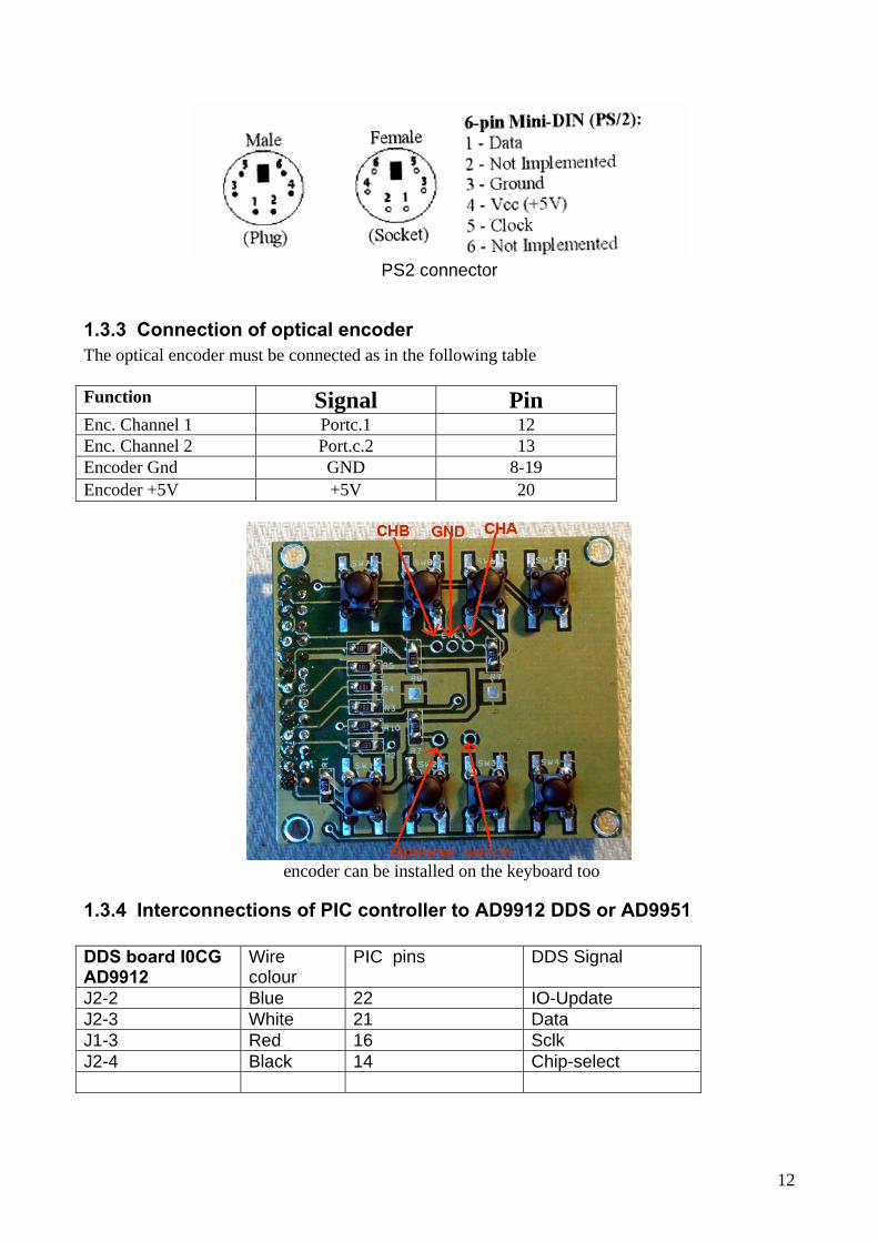
PS2 connector
1.3.3 Connection of optical encoder The optical encoder must be connected as in the following table Function Signal Pin Enc. Channel 1 Portc.1 12 Enc. Channel 2 Port.c.2 13 Encoder Gnd GND 8-19 Encoder +5V +5V 20
encoder can be installed on the keyboard too
1.3.4 Interconnections of PIC controller to AD9912 DDS or AD9951 DDS board I0CG AD9912
Wire colour
PIC pins DDS Signal
J2-2 Blue 22 IO-Update J2-3 White 21 Data J1-3 Red 16 Sclk J2-4 Black 14 Chip-select
13
J7 connector is near DDS PCB border DDS board I0CG AD9951
Wire colour
PIC pins DDS Signal
J1-2 Blue 22 IO-Update J1-3 White 21 Data J7-3 Red 16 Sclk J7-4 Black 14 Iosy
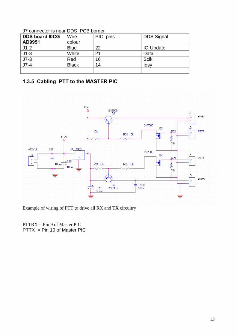
1.3.5 Cabling PTT to the MASTER PIC
Example of wiring of PTT to drive all RX and TX circuitry PTTRX = Pin 9 of Master PIC PTTX = Pin 10 of Master PIC

14
1.3.6 Expansion PIC connections The following schematics are only for Example. I haven’t made any PCB of this part.
See the connection between Main PIC Board and Expansion PIC board See also how 5V or 12 V relay can be connected directly to the Expansion Board. This relay can be used to switch RX Front-end filter or TX low pass Filter I/O used in the Expansion PIC (RX Front-end filter and TX low pass filter are (like Elecraft K2 ) Sw name = ESP_EL I/0 PIN
MICRO FUNTIONS
RC2 13 30 and 20 low pass RC3 14 80 m low pass RC4 15 40 m low pass Rc5 16 17 e 15 m low pass Rc6 17 12 e 10 m low pass Rc7 18 LSB = 1, USB = 0 RB0 21 Add C to tune 15 and 10 m Front-end filter to 17 and 12 m bands RB1 22 Front-end 10 m ( tuned to 12 m with RB0=0) RB2 23 Front-end 15 m ( tuned to 17 m with RB0= 1) RB3 24 Front-end 20 m (tuned to 30 m with RB5= 1) RB4 25 Front-end 40 m RB5 26 Add C to tune 80 and 20 m Front-end filter to 160 and 30 m bands RB6 27 Front-end 80 m (tuned to 160 m with RB5=1) RB7 28 AUXBUS
15
Table with I/O to interface a standard driver board( Sw ESP_std ) To any I/O is available command to drive 9 Ham band (160 to 10 m ) The logica level 0 enable the relevant Band Filter ( see the examples ) I/0 PIN
MICRO FUNTIONS
RC2 13 Comando banda 12 m RC3 14 Comando banda 10 m RC4 15 Rc5 16 Rc6 17 Rc7 18 LSB = 0, USB = 1 RB0 21 Comando banda 160 m RB1 22 Comando banda 80 m RB2 23 Comando banda 40 m RB3 24 Comando banda 30 m RB4 25 Comando banda 20 m RB5 26 Comando banda 17 m RB6 27 Comando banda 15 m RB7 28 Auxbus. Segnale seriale per comandare il PIC tramite PIC Master RA5 7 Comando Cw : 0 = Cw attivo, 1= Cw off
See in the last page of this document the Schematic of standard preselettore driver board
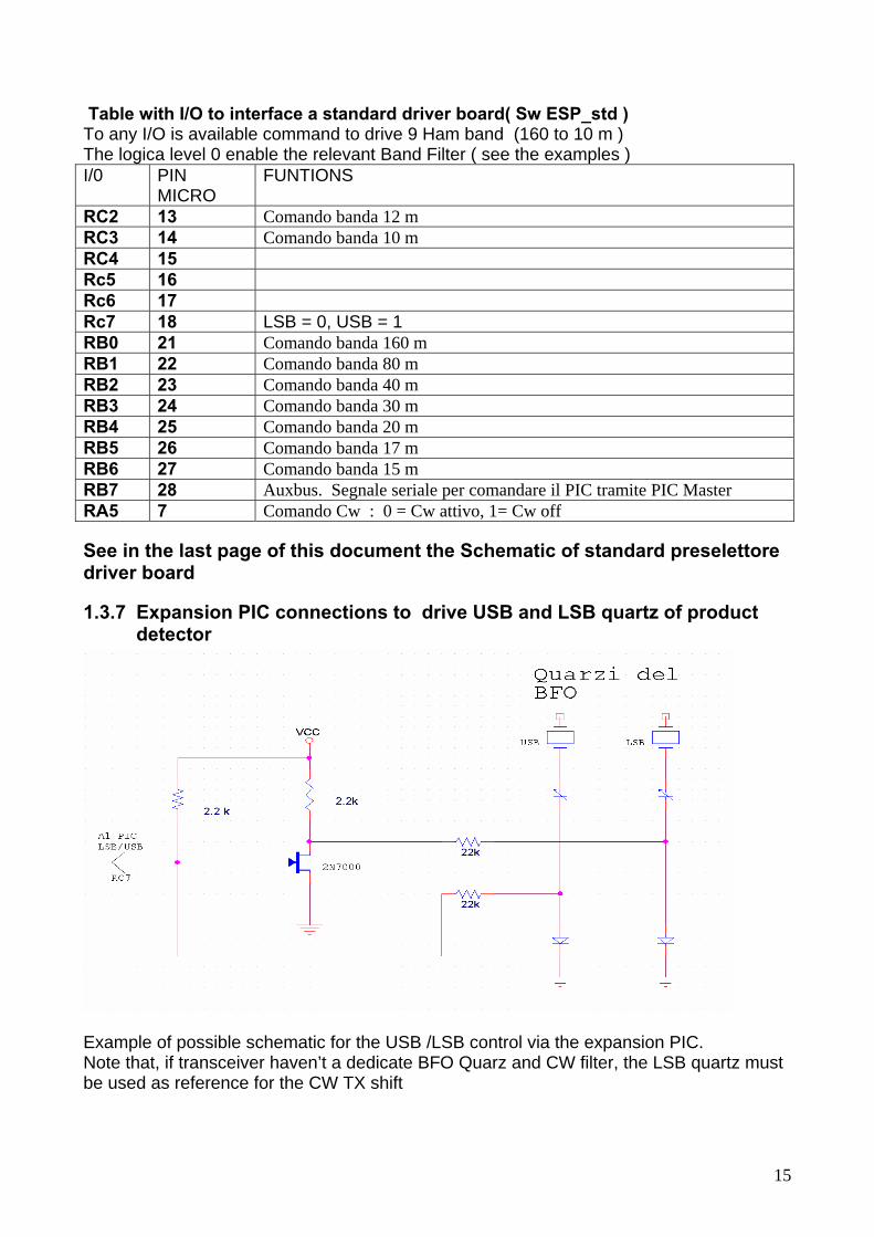
1.3.7 Expansion PIC connections to drive USB and LSB quartz of product detector
Example of possible schematic for the USB /LSB control via the expansion PIC. Note that, if transceiver haven’t a dedicate BFO Quarz and CW filter, the LSB quartz must be used as reference for the CW TX shift
16
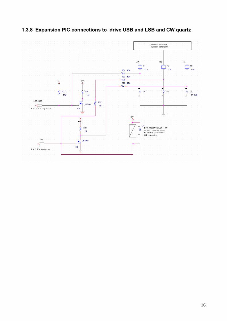
1.3.8 Expansion PIC connections to drive USB and LSB and CW quartz

17
1.4 My homebrew projects using this software
My all bands transceiver 1.8 -30 MHz (traditional one conversion using DDS instead of PLL )
My all band ( HF + 50 MHz ) SDR receiver

18
Inside my SDR receiver See the automatic preselector, the SDR main board with the DDS board fitted, the 1000 MHz osc. and the PIC panel
19
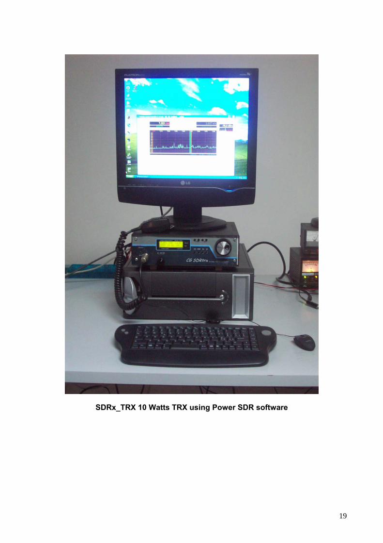
SDRx_TRX 10 Watts TRX using Power SDR software
20
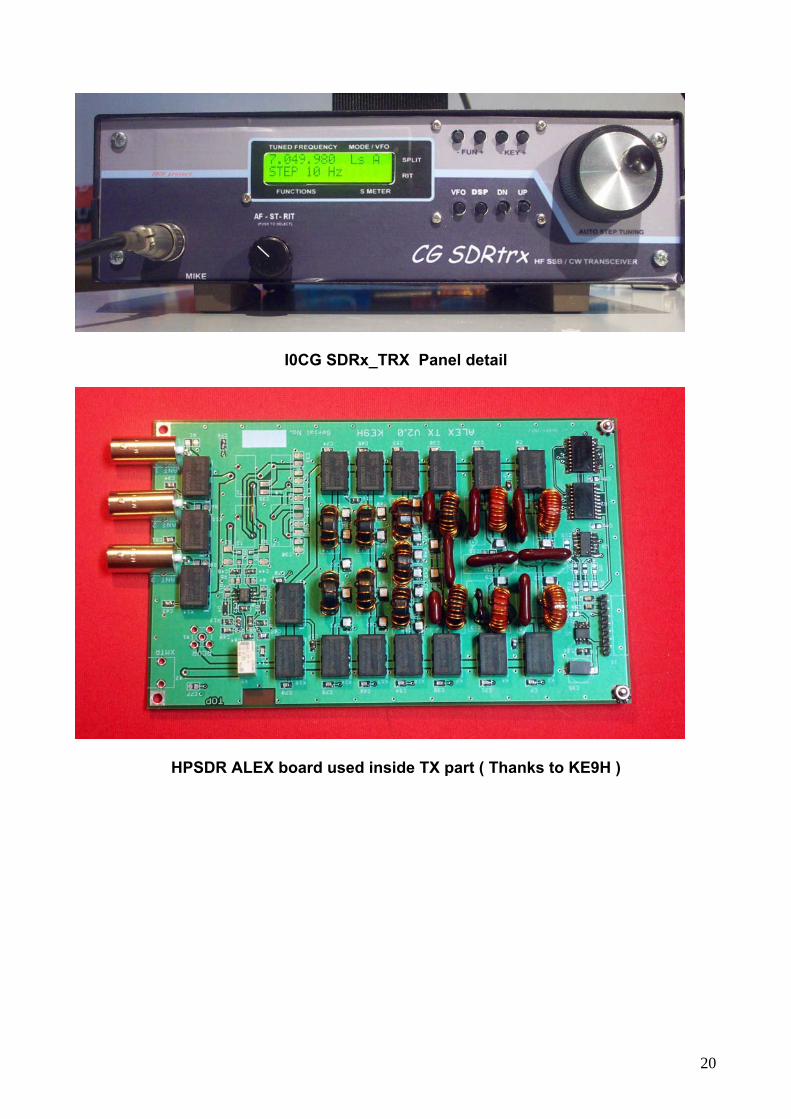
I0CG SDRx_TRX Panel detail
HPSDR ALEX board used inside TX part ( Thanks to KE9H )