Ijetae 0312 24
6
International Journal of Emerging Technology and Advanced Engineering Website: www.ijetae.com (ISSN 2250-2459, Volume 2, Issue 3, March 2012) 146 Modeling, Simulation and Implementation of Speed Control of DC Motor Using PIC 16F877A Payal P.Raval 1 , Prof.C.R.mehta 2 1 PG Student, Electrical Engg. Department, Nirma University, SG Highway, Ahmedabad, Gujarat, India. 2 Asst. Prof. Electrical Engg. Department, Nirma University, SG Highway, Ahmedabad, Gujarat, India. 1 [email protected] 2 [email protected] Abstract— The Microcontroller based adjustable closed-loop DC motor speed controller systems has already become an important drive configuration for many applications across a wide range of powers and speeds . This is due to their simple control, high reliability, low cost and fast response. Control System Design and Analysis technologies are widely suppress and very useful to be applied in real-time development. Some can be solved by hardware technology and by the advance used of software, control system are analyzed easily. Fractional HP DC Motors can be used in various applications and can be used as various sizes and rates. The designed circuit is stimulated using Real peak and MP LAB. In this paper, control techniques of PIC 16F877A microcontroller and MOSFET, mechanism assignments of analyzed by mainly focusing with the “Modeling and Simulation of DC Motor using MATLAB”. Keywords—DC Motor, MATLAB/ Simulink , PIC. I. INTRODUCTION Traditionally, the DC Motors and the associate close loop control systems used to drive them have been modeled using classic control theory techniques, based on transfer functions. Control system design and analysis technologies are widely suppress and very useful to be applied in real-time development. Some can be solved by hardware technology and by the advance used of software, control system are analyzed easily and detail. DC Motors can be used in various applications and can be used as various sizes and rates. The microprocessor computes the actual speed of the motor by sensing the terminal voltage. It then compares the actual speed of the motor with the reference speed and generates a suitable control signal which is fed into the triggering unit. This unit drives a Power MOSFET amplifier, which in turn supplies a PWM voltage to the dc motor. The objective of this paper is to explore the approach of designing a microcontroller based closed loop controller. The interface circuit and the software are all designed to achieve a better performance. The microcontroller system is equipped with an LCD display and a keypad and software was written to monitor the registers on the LCD and read commands from the keypad. Thus, by using the User Interface Module (UIM) the operator can view and/or change all the control and monitoring variables of the controller program. II. MODELING A DC MOTOR For modeling and simulation of a DC Motor, simple circuit of its electrical diagram as shown in Figure 1 is to be considered. A. Closed-Loop System Consideration To perform the simulation of the system, an appropriate model needs to be established. Therefore, a model based on the motor specifications needs to be obtained. Figure-1 shows the DC motor circuit with Torque and Rotor Angle consideration. Fig.1.Schematic Diagram of a DC Motor
-
Upload
memo-love -
Category
Engineering
-
view
34 -
download
5
Transcript of Ijetae 0312 24
International Journal of Emerging Technology and Advanced Engineering
Website: www.ijetae.com (ISSN 2250-2459, Volume 2, Issue 3, March 2012)
146
Modeling, Simulation and Implementation of Speed
Control of DC Motor Using PIC 16F877A
Payal P.Raval1, Prof.C.R.mehta
2
1PG Student, Electrical Engg. Department, Nirma University, SG Highway, Ahmedabad, Gujarat, India. 2Asst. Prof. Electrical Engg. Department, Nirma University, SG Highway, Ahmedabad, Gujarat, India.
Abstract— The Microcontroller based adjustable closed-loop
DC motor speed controller systems has already become an
important drive configuration for many applications across a
wide range of powers and speeds . This is due to their simple
control, high reliability, low cost and fast response. Control
System Design and Analysis technologies are widely suppress
and very useful to be applied in real-time development. Some
can be solved by hardware technology and by the advance
used of software, control system are analyzed easily.
Fractional HP DC Motors can be used in various applications
and can be used as various sizes and rates. The designed
circuit is stimulated using Real peak and MP LAB. In this
paper, control techniques of PIC 16F877A microcontroller
and MOSFET, mechanism assignments of analyzed by mainly
focusing with the “Modeling and Simulation of DC Motor
using MATLAB”.
Keywords—DC Motor, MATLAB/ Simulink , PIC.
I. INTRODUCTION
Traditionally, the DC Motors and the associate close
loop control systems used to drive them have been
modeled using classic control theory techniques, based on
transfer functions. Control system design and analysis
technologies are widely suppress and very useful to be
applied in real-time development. Some can be solved by
hardware technology and by the advance used of software,
control system are analyzed easily and detail. DC Motors
can be used in various applications and can be used as
various sizes and rates. The microprocessor computes the
actual speed of the motor by sensing the terminal voltage. It
then compares the actual speed of the motor with the
reference speed and generates a suitable control signal
which is fed into the triggering unit. This unit drives a
Power MOSFET amplifier, which in turn supplies a PWM
voltage to the dc motor.
The objective of this paper is to explore the approach of
designing a microcontroller based closed loop controller.
The interface circuit and the software are all designed to
achieve a better performance.
The microcontroller system is equipped with an LCD
display and a keypad and software was written to monitor
the registers on the LCD and read commands from the
keypad. Thus, by using the User Interface Module (UIM)
the operator can view and/or change all the control and
monitoring variables of the controller program.
II. MODELING A DC MOTOR
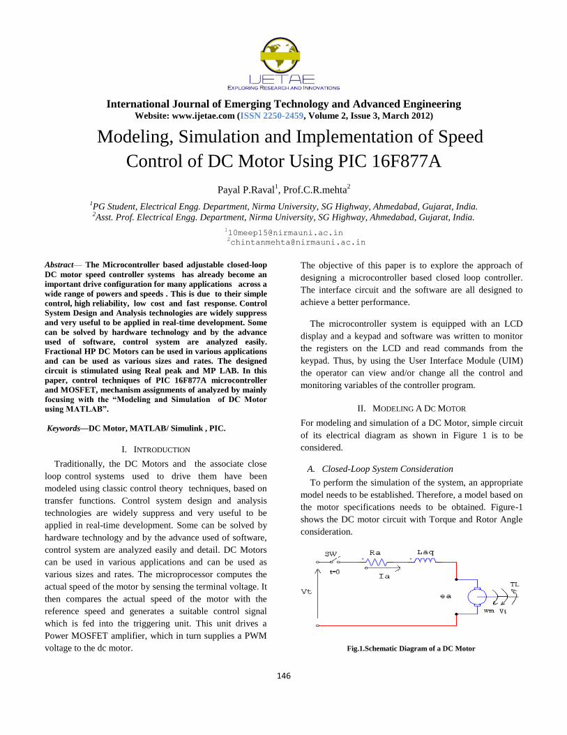
For modeling and simulation of a DC Motor, simple circuit
of its electrical diagram as shown in Figure 1 is to be
considered.
A. Closed-Loop System Consideration
To perform the simulation of the system, an appropriate
model needs to be established. Therefore, a model based on
the motor specifications needs to be obtained. Figure-1
shows the DC motor circuit with Torque and Rotor Angle
consideration.
Fig.1.Schematic Diagram of a DC Motor
International Journal of Emerging Technology and Advanced Engineering
Website: www.ijetae.com (ISSN 2250-2459, Volume 2, Issue 3, March 2012)
147
B. System Equation
The motor torque T is related to the armature current, i , by
a torque constant K;
(1)
The generated voltage, ea, is relative to angular velocity by
(2)
(3)
From Fig. 1 we can write the following equations based on
the
Newton’s law com bined with the Kirchoff’s law:
+ b = Ki (4)
+RI =V - K (5)
C. Transfer Function
Using the Laplace transform, equations (3) and (4) can be
written as:
(6)
(7)
Where s denotes the Laplace operator. From (7) we can
express I(s):
(8)
and substitute it in (5) to obtain:
(9)
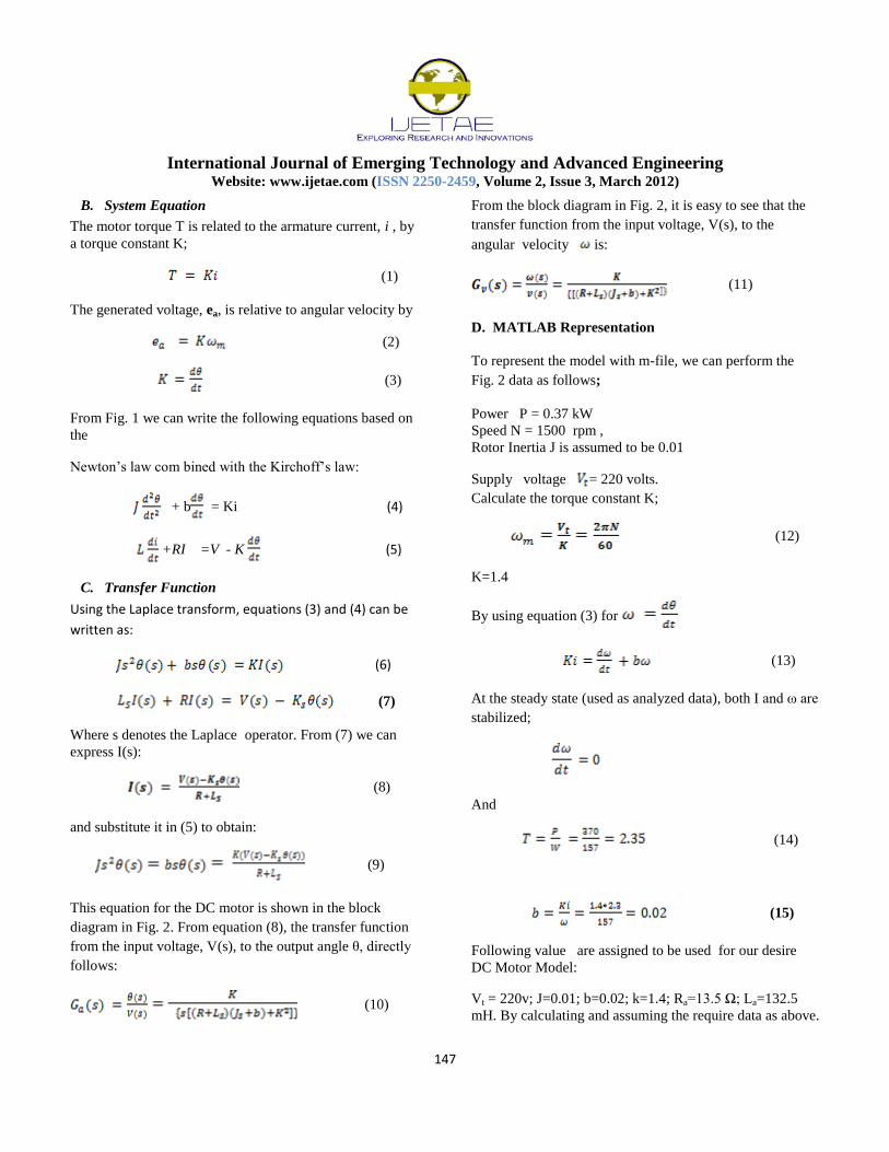
This equation for the DC motor is shown in the block
diagram in Fig. 2. From equation (8), the transfer function
from the input voltage, V(s), to the output angle θ, directly
follows:
(10)
From the block diagram in Fig. 2, it is easy to see that the
transfer function from the input voltage, V(s), to the
angular velocity is:
(11)
D. MATLAB Representation
To represent the model with m-file, we can perform the
Fig. 2 data as follows;
Power P = 0.37 kW
Speed N = 1500 rpm ,
Rotor Inertia J is assumed to be 0.01
Supply voltage = 220 volts.
Calculate the torque constant K;
(12)
K=1.4
By using equation (3) for
(13)
At the steady state (used as analyzed data), both I and ω are
stabilized;
And
(14)
(15)
Following value are assigned to be used for our desire
DC Motor Model:
Vt = 220v; J=0.01; b=0.02; k=1.4; Ra=13.5 Ω; La=132.5
mH. By calculating and assuming the require data as above.
International Journal of Emerging Technology and Advanced Engineering
Website: www.ijetae.com (ISSN 2250-2459, Volume 2, Issue 3, March 2012)
148
Figure.2 Closed loop system that Representing the DC motor
D. Analysis
We plot the step, impulse and frequency responses of the
given motor model:
Fig.3(a) Step response using simulink model.
Fig. 3(b) Impulse response using simulink model.
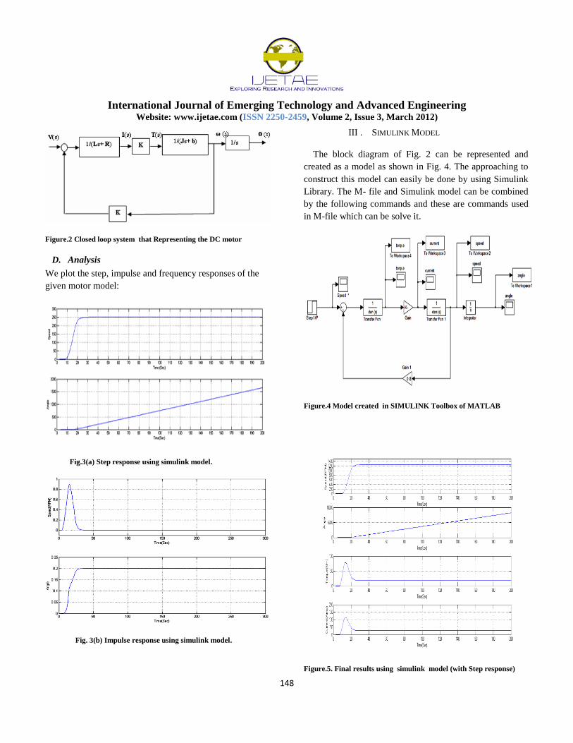
III . SIMULINK MODEL
The block diagram of Fig. 2 can be represented and
created as a model as shown in Fig. 4. The approaching to
construct this model can easily be done by using Simulink
Library. The M- file and Simulink model can be combined
by the following commands and these are commands used
in M-file which can be solve it.
Figure.4 Model created in SIMULINK Toolbox of MATLAB
Figure.5. Final results using simulink model (with Step response)
International Journal of Emerging Technology and Advanced Engineering
Website: www.ijetae.com (ISSN 2250-2459, Volume 2, Issue 3, March 2012)
149
IV. SYSTEM DESCRIPTION
The input from the stable power supply unit (230 V AC)
is converted into 12v AC by means of a step down
transformer, the output of this is used as input to bridge
rectifier circuit. Here in this system bridge rectifier will
generate 5 V DC with the help of regulator 7805. The
output of the 7805 regulator is used as an input to the PIC.
The PIC will generate pulses to drive the DC motor
according to the requirement. As the output voltage of the
PIC is in mV, driver circuits are used to drive the DC motor
An optical encoder is used to measure the speed of the
motor. The output of the encoder is a stream of pulses with
variable frequency according to the speed of the motor. The
optocouplers were used to isolate the high voltage circuits
from the low voltage controlling signals. The rating of the
motor should be chosen according to the rating of the
power circuit.
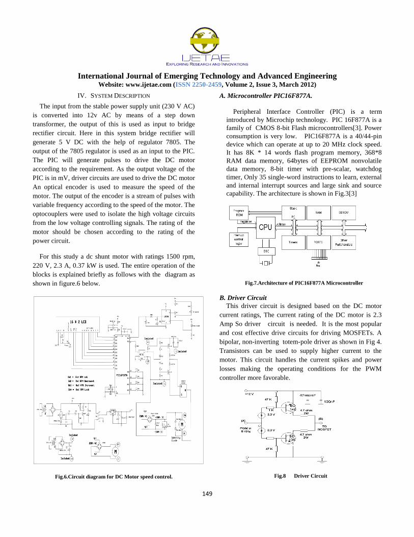
For this study a dc shunt motor with ratings 1500 rpm,
220 V, 2.3 A, 0.37 kW is used. The entire operation of the
blocks is explained briefly as follows with the diagram as
shown in figure.6 below.
Fig.6.Circuit diagram for DC Motor speed control.
A. Microcontroller PIC16F877A.
Peripheral Interface Controller (PIC) is a term
introduced by Microchip technology. PIC 16F877A is a
family of CMOS 8-bit Flash microcontrollers[3]. Power
consumption is very low. PIC16F877A is a 40/44-pin
device which can operate at up to 20 MHz clock speed.
It has 8K * 14 words flash program memory, 368*8
RAM data memory, 64bytes of EEPROM nonvolatile
data memory, 8-bit timer with pre-scalar, watchdog
timer, Only 35 single-word instructions to learn, external
and internal interrupt sources and large sink and source
capability. The architecture is shown in Fig.3[3]
Fig.7.Architecture of PIC16F877A Microcontroller
B. Driver Circuit
This driver circuit is designed based on the DC motor
current ratings, The current rating of the DC motor is 2.3
Amp So driver circuit is needed. It is the most popular
and cost effective drive circuits for driving MOSFETs. A
bipolar, non-inverting totem-pole driver as shown in Fig 4.
Transistors can be used to supply higher current to the
motor. This circuit handles the current spikes and power
losses making the operating conditions for the PWM
controller more favorable.
Fig.8 Driver Circuit
International Journal of Emerging Technology and Advanced Engineering
Website: www.ijetae.com (ISSN 2250-2459, Volume 2, Issue 3, March 2012)
150
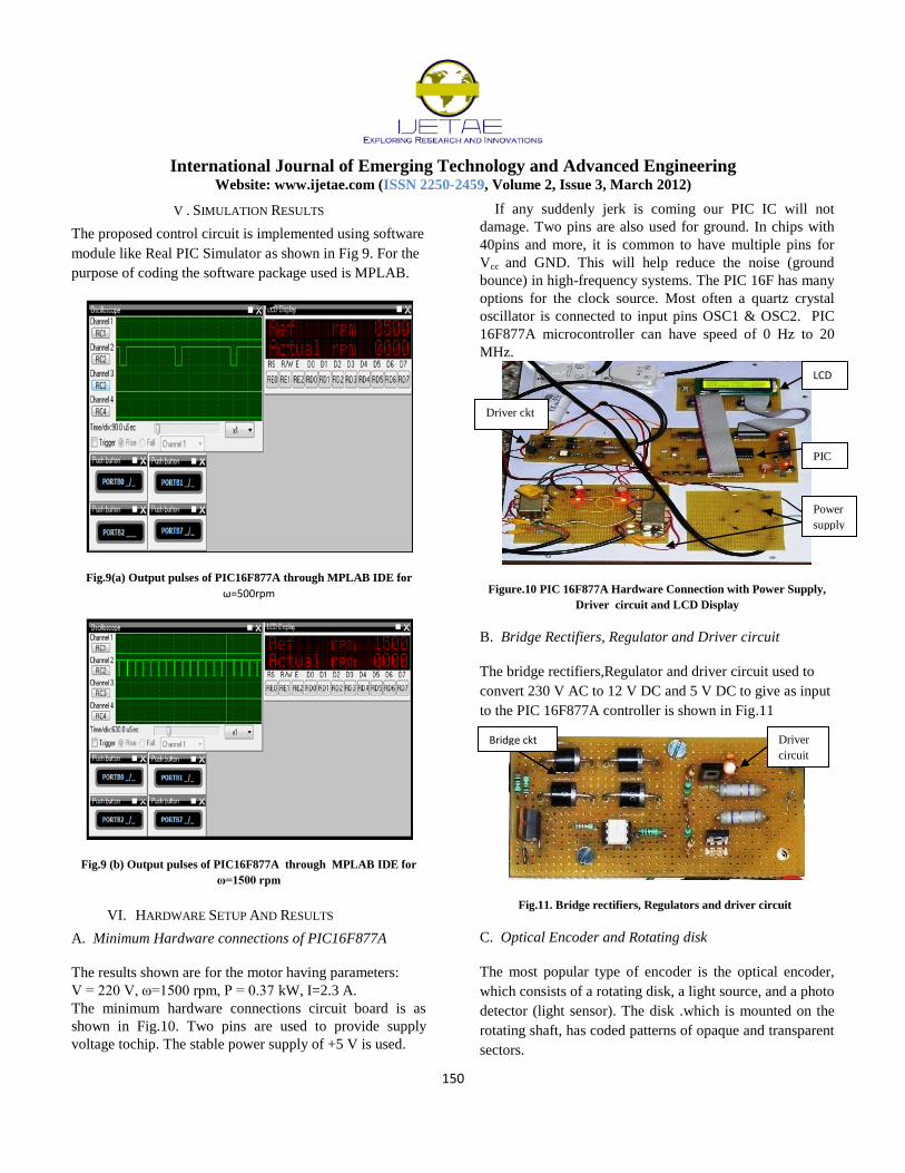
V . SIMULATION RESULTS
The proposed control circuit is implemented using software
module like Real PIC Simulator as shown in Fig 9. For the
purpose of coding the software package used is MPLAB.
Fig.9(a) Output pulses of PIC16F877A through MPLAB IDE for
ω=500rpm
Fig.9 (b) Output pulses of PIC16F877A through MPLAB IDE for
ω=1500 rpm
VI. HARDWARE SETUP AND RESULTS
A. Minimum Hardware connections of PIC16F877A
The results shown are for the motor having parameters:
V = 220 V, ω=1500 rpm, P = 0.37 kW, I=2.3 A.
The minimum hardware connections circuit board is as
shown in Fig.10. Two pins are used to provide supply
voltage tochip. The stable power supply of +5 V is used.
If any suddenly jerk is coming our PIC IC will not
damage. Two pins are also used for ground. In chips with
40pins and more, it is common to have multiple pins for
Vcc and GND. This will help reduce the noise (ground
bounce) in high-frequency systems. The PIC 16F has many
options for the clock source. Most often a quartz crystal
oscillator is connected to input pins OSC1 & OSC2. PIC
16F877A microcontroller can have speed of 0 Hz to 20
MHz.
Figure.10 PIC 16F877A Hardware Connection with Power Supply,
Driver circuit and LCD Display
B. Bridge Rectifiers, Regulator and Driver circuit
The bridge rectifiers,Regulator and driver circuit used to
convert 230 V AC to 12 V DC and 5 V DC to give as input
to the PIC 16F877A controller is shown in Fig.11
Fig.11. Bridge rectifiers, Regulators and driver circuit
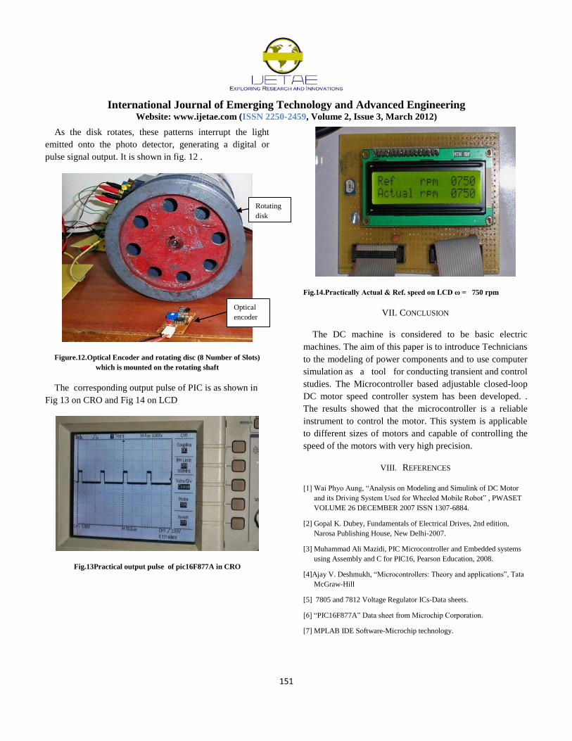
C. Optical Encoder and Rotating disk
The most popular type of encoder is the optical encoder,
which consists of a rotating disk, a light source, and a photo
detector (light sensor). The disk .which is mounted on the
rotating shaft, has coded patterns of opaque and transparent
sectors.
Bridge ckt Driver
circuit
LCD
PIC
Power
supply
s
Driver ckt
International Journal of Emerging Technology and Advanced Engineering
Website: www.ijetae.com (ISSN 2250-2459, Volume 2, Issue 3, March 2012)
151
As the disk rotates, these patterns interrupt the light
emitted onto the photo detector, generating a digital or
pulse signal output. It is shown in fig. 12 .
Figure.12.Optical Encoder and rotating disc (8 Number of Slots)
which is mounted on the rotating shaft
The corresponding output pulse of PIC is as shown in
Fig 13 on CRO and Fig 14 on LCD
Fig.13Practical output pulse of pic16F877A in CRO
Fig.14.Practically Actual & Ref. speed on LCD ω = 750 rpm
VII. CONCLUSION
The DC machine is considered to be basic electric
machines. The aim of this paper is to introduce Technicians
to the modeling of power components and to use computer
simulation as a tool for conducting transient and control
studies. The Microcontroller based adjustable closed-loop
DC motor speed controller system has been developed. .
The results showed that the microcontroller is a reliable
instrument to control the motor. This system is applicable
to different sizes of motors and capable of controlling the
speed of the motors with very high precision.
VIII. REFERENCES
[1] Wai Phyo Aung, “Analysis on Modeling and Simulink of DC Motor
and its Driving System Used for Wheeled Mobile Robot” , PWASET
VOLUME 26 DECEMBER 2007 ISSN 1307-6884.
[2] Gopal K. Dubey, Fundamentals of Electrical Drives, 2nd edition,
Narosa Publishing House, New Delhi-2007.
[3] Muhammad Ali Mazidi, PIC Microcontroller and Embedded systems
using Assembly and C for PIC16, Pearson Education, 2008.
[4]Ajay V. Deshmukh, “Microcontrollers: Theory and applications”, Tata
McGraw-Hill
[5] 7805 and 7812 Voltage Regulator ICs-Data sheets.
[6] “PIC16F877A” Data sheet from Microchip Corporation.
[7] MPLAB IDE Software-Microchip technology.
Optical
encoder
Rotating
disk