IIIIII I II - dtic.mil · UNIFIE IIIIII I II I AD-RI39 ACTIVE 741 NO~~~~~IS EUTOW BOECRFAMNHMAS i/...
43
UNIFIE IIIIII I II I AD-RI39 741 ACTIVE NO~~~~~~IS EUTOW BOECRFAMNHMAS i/
-
Upload
trinhduong -
Category
Documents
-
view
214 -
download
0
Transcript of IIIIII I II - dtic.mil · UNIFIE IIIIII I II I AD-RI39 ACTIVE 741 NO~~~~~IS EUTOW BOECRFAMNHMAS i/...
UNIFIE IIIIII I II
IAD-RI39 741 ACTIVE NO~~~~~~IS EUTOW BOECRFAMNHMAS i/

I,,'
1.2 1.
.
a4
111110 lllg I2
MICROCOPY RESOLUTION TEST CHART
NATIONIAI. S*UAAU OF STAIAOD$ - IS A
j.,
4.V

AFAMRL-TR-84-008
ACTIVE NOISE REDUCTION
JOHN CARTER
\BOSE CORPORATION100 THE MOUNTAIN ROADFRAMINGHAM MA 01701
JANUARY 1984
Approved for public release; distribution unlimited
L.
C...'
AEROSPACE MEDICAL RESEARCH LABORATORYAEROSPACE MEDICAL DIVISIONAIR FORCE SYSTEMS COMMAND
s WRIGHT PATTERSON AIR FORCE BASE, OHIO 45433
84 04 05 017

T%,. 7 .. , - % ** ~ C -
SECURITY CLASSIFICATION OF THIS PAGE (*'huen Date Entered)
REPORT DOCUMENTATION PAGE BFRE COMPLETINSOR
1. REPORT NUMBER 2. GOTEjIN RECIPIENT'S CATALOG NUMBER
%AFAMRL-TR-84-008 '9 r ______ _______4 ACTIVE NOISE REDUCTIONe. S. PERFORMING ORG. REPORT NUMBER
7. AUTHOR(q) S. CONTRACT OR GRANT NUMBER(a)
JOHN CARTER F33615-82-C-O521
9. PERFORMING ORGANIZATION NAME AND ADDRESS 10. PROGRAM ELEMENT. PROJECT, TASKAREA & WORK UNIT NUMBERS
BOSE CORPORATION100 THE MOUNTAIN ROAD 62202F, 72310921FRAMINGHAM MA 01701 ______________
11. CONTROLLING OFFICE NAME AND ADDRESS 12. REPORT DATE
AEROSPACE MEDICAL RESEARCH LABORATORY January 1984 kAEROSPACE MEDICAL DIVISION, AIR FORCE SYSTEMS 13. NUMBER OF PAGES
COMMAND. WRIGHT-PATTESNARFRERS-O 53 3814. MONITORING AGENCY NAME & ADDRESS(iI different from Controlling Office) 15. SECURITY CLASS. (of this report)
UNCLASSI FIED
15a. DECL ASSI FICATION/ DOWNGRADINGSCHEDULE
16. DISTRIBUTION STATEMENT (of thie Report)
%
Apprved fors peulioees;dnrbuinulmtc
4C 27. DISTRIBUTIO STATEMENT (of ree hese btract nd Inify lo y 20,c ifudifer) frmReot
Aciv Nos Reuci (AR ehiqesnl adi obiainwt
of. KeY ig WOD aCnu onpeeraidn, pfrntotype andidniain bnd blortiok numnd
-ewtAciv Heain Protec73 ED TIO n 5I14 TActveNos Redutio
SoundIT ProtectionF HS AG NnDae nerdHerig roecioB4.

SECURITY CLASSIFICATION OF THIS PAGE(When Date Entered)
electroacoustic performance and specifications for the AMR system. Thissystem is theoretically capable of oroducinq in excess of 30 decibels ofactive noise reduction. Electroacoustic measurements on a flat plate couplerdemonstrated approximately 20 decibels of active noise reduction with theprototype unit. A performance evaluation of the inteqrated ANR unit will beconducted under laboratory and field conditions by government personnel todetermine the feasibility of the system for use in military applications.
oa
a.4

NOTICES
When US Government drawings, specifications, or other data are used for any purpose other than adefinitely related Government procurement operation, the Government thereby incurs no responsibilitynor any obligation whatsoever, and the fact that the Government may have formulated, furnished, orin any way supplied the said drawings, specifications, or other data, is not to be regarded byimplication or otherwise, as in any manner licensing the holder or any other person or corporation, or
conveying any rights or permission to manufacture, use, or sell any patented invention that may in anyway be related thereto.
Please do not request copies of this report from Air Force Aerospace Medical Research Laboratory.Additional copies may be purchased from:
National Technical Information'Service5285 Port Royal RoadSpringfield, Virginia 22161
Federal Government agencies and their contractors registered with Defense Technical InformationCenter should direct requests for copies of this report to:
Defense Technical Information CenterCameron StationAlexandria, Virginia 22314
TECHNICAL REVIEW AND APPROVALAFAMRL-TR-84-008
This report has been reviewed by the Office of Public Affairs (PA) and is releasable to the NationalTechnical Information Service (NTIS). At NTIS, it will be available to the general public, includingforeign nations.
Thi3 technical report has been reviewed and is approved for publication.
FOR THE COMMANDER
.. -: . I " ' . . .
HENNING E. VON GIERKE, Dr IngDirectorBiodynamics and Bioengineering l)ivisionAir Force Aerospace Medical Research Laboratory ,
pCOX
INS," 15;0 "1,00

CONTENTS
Preface ............................ 3
Introduction................................................ 4
Purpose..................................................... 4
Background.................................................. 4
Approach.................................................... 7
Prototype Configuration ...................................... 8
Prototype Operation .......................................... 8
Theory of Operation .......................................... 8
Electroacoustic Performance and Specifications ................17
Relative Performance ... *.....................................26
Di c s i n. . . . . . . . . . . .. . . . . . . . . . . . . . .2
ReDicussndions..............................................26
jReferences ................................................. 30*Appendix I Use's Guide................................... 31
4Appendix II- Theory of Design ............................... 33
-2-

PREFACE
This report describes work that involved the fabrication of an Active NoiseReduction (ANR) system and its integration into an Air Force flight helmet.IThe work was accomplished by the BOSE Corporation under Air Force ContractF33615-82-C-0521. This effort was supported by the Life Support SystemsProgram Office, Operational Systems Support Division, Aeronautical SystemsDivision and technically administered by the Biological Acoustics Branch,Biodynamics and Bioengineering Division, Aerospace Medical ResearchLaboratory. It was accomplished under Project 7231, "Biomechanics of
* Aerospace Operations"' and Task 723103, "Communication and PerformanceCapability in Operational Noise." Air Force project engineers were Mr.Richard McKinley and Lt William Decker. BOSE personnel responsible for thework were John Carter, Roman Sapiejewski, Dan Gauger and Norman Stickney.
gili
.1
3-
~V

INTRODUCTION
In many noise environments it is not practical, economical or feasible toreduce noise levels at the ear of a listener to within acceptable limits usingengineering controls. In some of these situations an acceptable noise levelat the ear may be achieved with the use of personal hearing protection in theform of ear plugs, earmuffs, helmets or combinations of these devices. Inother situations, the performance of the hearing protector is not fullyacceptable allowing noise levels at the ear that may interfere withactivities, degrade performance or even pose a threat to hearing, if ofappropriate magnitude, frequency and duration. The concept of active noisereduction (ANR) was successfully demonstrated several decades ago as apotential means of enhancing the performance of hearing protection to providesatisfactory comizication and protection in situations where they are notachievable with passive devices. At that time, various instrumentation andsystem constraints prevented the concept from being reduced to practice.Recently, the BOSE Corporation demonstrated a laboratory prototype ActiveNoise Reduction system that appears to have resolved most of the majorconstraint problems of the earlier systems and to have created the potentialfor a practical ANR system.
PURPOSE
The purpose of this project is to evaluate the effectiveness of hearingprotection and voice communication performance with the BOSE Corporationactive noise reduction technique integrated into an Air Force flight helmet.The purpose of this report is to describe the active noise red~ction system,its operation and its performance.
BACKGROUND
Three fundamental types of active noise reduction have been demonstrated withvarying degrees of success; open loop, closed loop and digital adaptivesystems. These systems vary in complexity, advantages-disadvantages, andeffectiveness. Although there are variations in theory and operation of thesesystems, they all operate on the principle of noise cancellation at the ear.
Open loop active noise reduction systems operate by measuring the noiseoutside the ear enclosure, adjusting the spectrum and level to approximatethose of the noise inside the enclosure, inverting the phase of the signal 180degrees and presenting the adjusted signal to cancel the noise inside the earenclosure. Figure 1 shows a block diagram of this approach. Cancellation isonly partially successful because the adjustment of spectrum and level isstrongly dependent upon the seal and the fit of the enclosure which varies
from user to user. Its effectiveness is limited to frequencies below about800 Hz. The open loop system may produce more noise inside the enclosure than
*.* the passive system alone if it is operating improperly. The open loop systemrequires an effective acoustic seal of the ear enclosure for satisfactoryoperation.
-4-

HEARING PROTECTOR
' ' /EXTERNAL MICROPHONE
E FILTER POWER0 AMPLIFIER
ELEMENT *a00 MICROPHONE INVERTERi .! PREAMPLIFIER
Figure 1. Block Diagram of Open Loop
Active Noise Reduction System.
The adaptive digital noise reduction technique operates in an open loop modewhere the adjustments of the outside signal to form the cancellation signalare done with digital techniques that continually adapt to changes in theoutside noise signal. This system Is shown in Figure 2. The speed with whichthe outside noise is digitized, processed and reconstructed is less thanactual real time and a consequence is that the transient sound is not reallyeliminated. Adaptive digital techniques may be more costly than the moreconventional analog systems. Their effectiveness is limited to frequencies ofabout 800 Hz and below and the amount of noise reduction is expected to beabout 6 to 12 dB.
A5
% % %

V11, ~ aj W- # J 97 q.;; I* q. 74t
ERROR SIGNAL
MOIO 0AATV ADAPTATION REAL TIMEALGORTHM SGNAL PROCESSINGALGORITH COMPUTER
CREFERENCE MICROPHONE
REFERENCE SIGNAL
Figure 2. Block Diagram of AdaptiveDigital Noise Reduction System.
MICROPHONE
ELEMENT
Figure 3. Block Diagram of Closed LoopActive Noise Reduction System.
I% N N-6 -9-0

Closed loop systems operate on essentially the same principles as the openloop systems except that the initial measurement of the noise takes placeinside the ear enclosure. The primary advantage of the closed loop over openloop systems Is that the process of adjusting the measured noise to become acancellation signal is greatly simplified. The noise measured inside theenclosure is continuously corrected to match the input signal, shifted 180degrees in phase and reintroduced to achieve the cancellation. Figure 3 showsa block diagram of the closed loop approach. The closed loop system may beexpected to provide better performance than open loop because of the somewhatmore efficient cancellation signal. Time delay in the prototype system limitsthe noise reduction effectiveness to frequencies below about 800 Hz. Anacoustic seal of the ear enclosure is not essential to the successfuloperation of the closed loop noise reduction system.
The BOSE Corporation active noise reduction system is an enhanced closed loopsystem. The proprietary methodology of "frequency domain optimal compensation"developed by BOSE has been incorporated into their prototype Model 2081.Model 2081 is theoretically capable of producing active noise reductions thatwill exceed 30 decibels. The frequency response of the system is reasonablyflat and the output signal has low distortion. The theory of design of theBOSE Corporation Model 2081 system is described in Appendix II.
A comparative evaluation of these active noise reduction techniques revealsthat the advantages of the BOSE Model 2081 active noise reduction prototypemake it the logical choice for investigating the feasibility of ANR inmilitary applications.
APPROACH
The BOSE Model 2081 active noise reduction system has been miniaturized andincorporated into a standard Air Force flight helmet (HGU-26/P). Themodification includes fabrication of appropriate cables and connectors toallow the AN helmet to be mated either with laboratory equipment or with AFaircraft communication systems.
The Integrated AU (IANR) helmet will be evaluated in laboratory tests by BOSECorporation for appropriate electronic performance and for active, passive andactive-passive noise reduction on a flat plate coupler. The IANR helmet willbe transported to AFAMRL/UBA for additional laboratory and field tests. Datafrom these tests will be analyzed to determine the feasibility of the BOSE AUfor military applications.
-7-
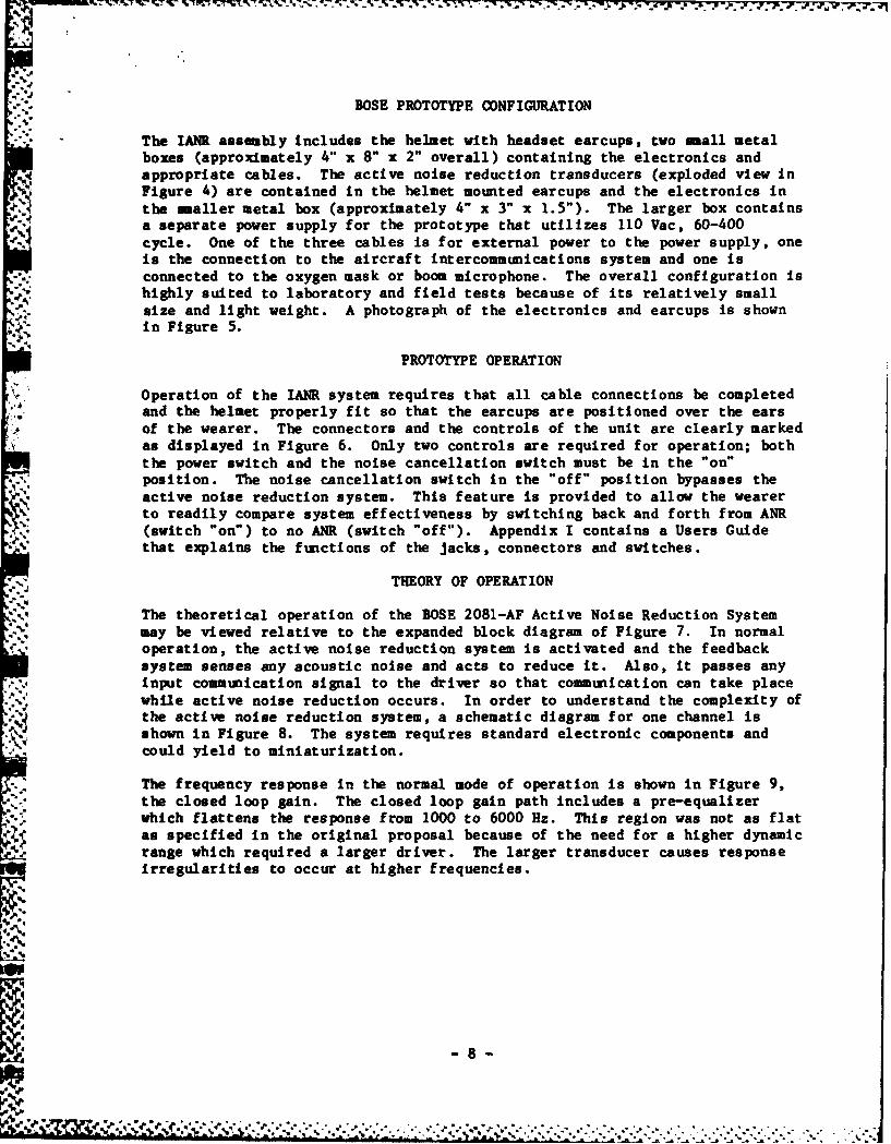
BOSE PROTOTYPE CONFIGURATION
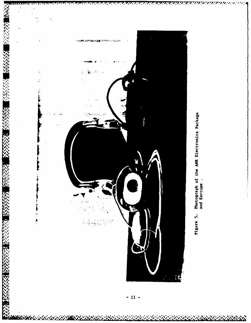
The IANR assembly includes the helmet with headset earcups, two small metalboxes (approximately 4" x 8" x 2" overall) containing the electronics andappropriate cables. The active noise reduction transducers (exploded view inFigure 4) are contained in the helmet mounted earcups and the electronics inthe smaller metal box (approximately 4" x 3" x 1.5"). The larger box containsa separate power supply for the prototype that utilizes 110 Vac, 60-400cycle. One of the three cables is for external power to the power supply, oneis the connection to the aircraft intercommunications system and one is
.. connected to the oxygen mask or boom microphone. The overall configuration ishighly suited to laboratory and field tests because of its relatively smallsize and light weight. A photograph of the electronics and earcups is shownin Figure 5.
PROTOTYPE OPERATION
Operation of the IANR system requires that all cable connections be completed
and the helmet properly fit so that the earcups are positioned over the ears
of the wearer. The connectors and the controls of the unit are clearly markedas displayed in Figure 6. Only two controls are required for operation; boththe power switch and the noise cancellation switch must be in the "on"position. The noise cancellation switch in the "off" position bypasses theactive noise reduction system. This feature is provided to allow the wearerto readily compare system effectiveness by switching back and forth from ANR(switch "on") to no ANR (switch "off"). Appendix I contains a Users Guidethat explains the functions of the jacks, connectors and switches.
THEORY OF OPERATION
The theoretical operation of the BOSE 2081-AF Active Noise Reduction Systemmay be viewed relative to the expanded block diagram of Figure 7. In normaloperation, the active noise reduction system is activated and the feedbacksystem senses any acoustic noise and acts to reduce it. Also, it passes anyinput communication signal to the driver so that communication can take placewhile active noise reduction occurs. In order to understand the complexity ofthe active noise reduction system, a schematic diagram for one channel isshown in Figure 8. The system requires standard electronic components andcould yield to miniaturization.
The frequency response in the normal mode of operation is shown in Figure 9,the closed loop gain. The closed loop gain path includes a pre-equalizer
which flattens the response from 1000 to 6000 Hz. This region was not as flatas specified in the original proposal because of the need for a higher dynamicrange which required a larger driver. The larger transducer causes responseirregularities to occur at higher frequencies.
-8-
.. . .. .

..- . . . . . . . . . . ...
The active noise reduction function is eliminated when the noise cancellationswitch is in the "off" position, however, the communication signal is stillapplied to the driver. A bypass equalizer is required because the response ofthe driver is not flat without the servo system as it is when the noisereduction is activated. The bypass equalizer approximates the response of theclosed loop system. It is difficult to equalize both paths to be exactly thesame because the response of the driver is fairly irregular above 3000 Hz.However, they are very close if the responses are viewed in terms of octavebands.
9 --
a.,,' . . , .',. .. . . . .',.' ;,..,' ,., . - .. .. . ... -, . , ... . .. .. .. . . . .- . . ... . ,.. - ,. .,,.,. -.'.

4:)
-C
Il
0 IL
0r
0
ul
4L 0
"IL 0
0440.0
u a
-0
iu
00
.P4
04
000I-o 0
100
S... , . _-.-. . _ . ., .,- , ., a . ¢ .. ., '."''t. -.-. ':. , ;". .' "' :"""""''".''. .- J.. "t '. " ' """--" "'," '"-"" " '' ' '.9
00 u, u uu ,a . ,, ' . - , " . -
Zr
00sU
0WVa
ILa Uw
sillS

U..)
Cu
0
Cu
00t4, W
0 l
4

LU
aLuLLu 2
U.
44
£U 0 q
Vr ca
UU
u. L
4' z
U 3cn 04
Lu
040
zz
0) (4o "
z Z0. IJ
4 1 1.40
4' -12-
'22!

z zZ a
0 0I
0 WW W 6
0a.- 0 su u-
00
Lw LL
,4 0
z zz
'5--
- I 0 x~ 10L
x~ 5- u. 4 a
S0 06
z uz zIL2 t 0 u
E bI~q~$duJ(A
0 0 0u u u "
oII
woim.0
13.

ILI -V TR .7 ..% e.-.-..--.'
4AAA
-i r
I0
a~~w 0 w
Q 0a
4y'sS
141

ii 0
u u
I~~F - ..- pq---
Ii I I
_____ G___ U)__ 0 I 00C I I
I1 -

Aq
A The prototype also includes compressor circuits to counteract large acoustictransients that cause the system to clip peaks, creating spurious sounds inthe earcup. The loop gain is reduced when signals are detected that wouldcause the power amplifier to clip. This has two effects; first, it preventslarge acoustic signals from reaching the ear. Second, it reduces the amountof active noise reduction. In normal operation (i.e., sound fields up to125 dB(C)) the compressor is not operational. However, it will operateautomatically when the earcup is mechanically displaced, or when the system issubject to a large acoustic transient. The compressor has very sharp"turn-on" characteristics as a function of level.
A
-16
- tf " *

ELECTROACOUSTIC PERFORMANCE AND ENGINEERING SPECIFICATIONS
All performance tests reported herein were conducted at the BOSE Corporationon a flat plate acoustic coupler, unless noted. The acoustic couplercontained a B & K 4134, 1/2 inch microphone positioned with the grid flushwith the plate surface. A 0.5 kg mass was placed on the earcup positioned onthe flat plate coupler to provide the same force for all earcups measuredduring the performance tests. The following section is numbered in accordancewith other BOSE specifications.
1.0 PERFORMANCE SPECIFICATIONS
1.1 Open Loop Gain. This is the quantity GH as discussed in Appendix IIthat characterizes the overall performance level of the system. SeeFigures 10 and 11.
1.2 Acoustical Isolation. Active Component - This flat plate measurementdoes not include the passive attenuation provided by the earcupenclosure. See Figures 10 and 11.
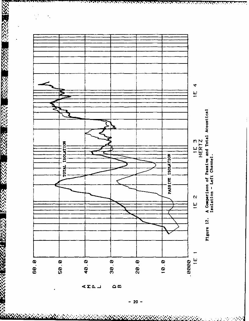
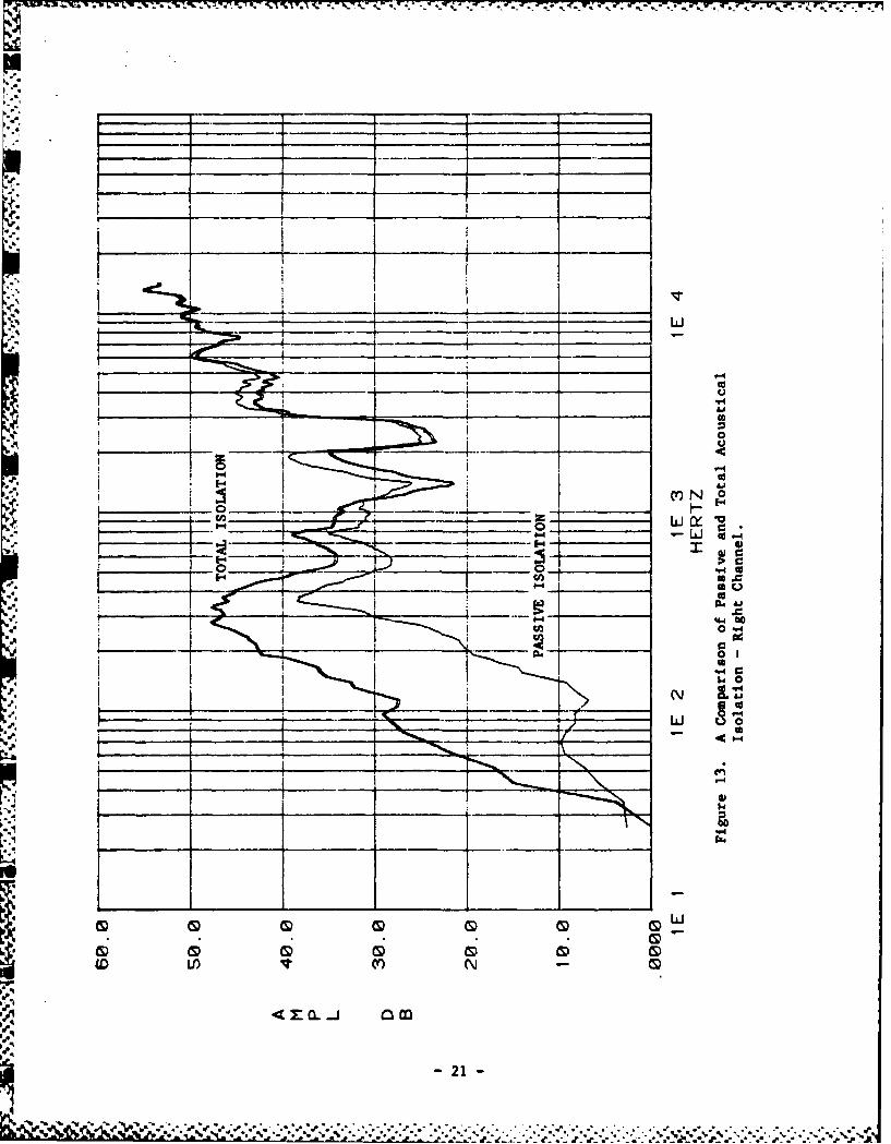
1.3 Acoustical Isolation. Passive and Total Components - See Figures 12and 13.
1.4 Maximum Sound Pressure Level for Cancellation: 124 dB Pink noise of60 Hz to 6000 Hz; 4:1 crest factor, as measured in reverberant room(C weighted).
1.5 Electrical Power Output (per channel): 1W 15 Hz to 6000 Hz, 100 ohmload.
1.6 A sine wave is applied to the communication signal input.Acoustical, 105 dB SPL output.
Frequency %THD60 Hz 5
120 Hz 2240 Hz 1500 Hz 0.5
1000 Hz 0.22000 Hz 0.54000 Hz 1
. .- 1
!.!.1m. •
•e - 17 -
,,. .. , , , o .. ., , ,. . . . . .. ,.,. ,, ... ,-. . . , .,- . ,,_o-* .44 , . -

*- .1, 3, -. .ll R-. M R $ ~ ~ 3 5 * . . *
.5.i
-. 58
0 u
*0 m

.4Xl'
4'l
a P
* ~ ~~~~~ 0 _ _ __ _ - -I-___ _ _ _ _ _ _ __ _ _ _ _1
____~~~~ &V__ __ _ _ 1_
JLL w .
__ uc
P-4 -A
41
0
19-i
yr-
LiJ
00
040
C ~ "4
-U 0
P4
4 x 0. -1 4.4
200
.1LJ
* 0
"41
Ir N 0
I cc'
ca 0
___ __ __ LLJ U
-~0
CS) C!D.'"-p!
CD M C G M0CLD (Y) Ca
4 TZ C -j a
_____ ____ ____ __21

-- 7- - -." -9.
1.7 Acoustical Frequency Response
60 Hz - 6000 Hz 5.0 dB maximum60 Hz - 3000 Hz + 3- 5.0 dB
See Figures 14 and 15, Closed Loop Response. The closed loop" frequency response is the response of the system to communication
signals at the input.
Figures 14 and 15 also show the response when the noise cancel switchis in the off position. This is an equalized frequency responsedesigned to approximate the noise cancel in response. This switchallows one to evaluate active noise reduction without changing thefrequency response.
1.8 Channel Balance
2.0 dB at 1000 Hz
1.9 Input Impedance
10,000 ohms
1.10 Signal-to-Noise Ratio
74 dB(A), reference to 105 dB SPL
- 1.11 Compressor-Limiter
A compressor prevents the power amplifier from clipping when thesystem is subject to mechanical or acoustic overloads. It acts onlywhen the level is greater than 125 dB SPL.
1.12 AC Power Requirements
110 Vac, 60 - 400 Hz
1.13 Power Consumption
2.5 watts In 105 dB SPL noise field (power to electronics).
2.0 MECHANICAL DESIGN
2.1 Controller
See Appendix I, User's Guide.
2.2 Headset
Driver and microphone required for servo system to be built into,-. modified HGU-26/P, flight helmet.
C-
p ~'e~a -22-
-C . . .C . . . "-..•., :''.:.,'-.-. .(':'-... ..A '; ,. '" . " -" ." " , . '" " .".,"

50A1 Ai-
04-
4~C __. r._
_t x01~
_~~~~4 CO _ _ ~ L
&~t cc S.
&~~~ 0i u LI0i I I
I i III IIIS
-23- c
45 -A

-
4p
0 g
* ____ I ... ___ - - ___
4.U A____
*1. ___ ___ ____ __ ____ _ _ ____ __ ____ ___ ___ ___ _ __ ___
CcJ4---------- 0
_____~C- CLLi %J_ _ _s _ _ _ _
wu-
4 .4) 0
Nz uIN*.4to~
Go
Gi G LI) G LC) G) QLI)() G )ID CD U) G ND CD) ULCDI Lb)
I~ I~ Ir (Y v IT In U
-24 -

3.0 TEST CONDITIONS
3.1 Source
120 Vac, 60 Hz
3.2 Testing
All electrical and acoustical specifications to be tested after 24hours continuous operation with pink noise input at an out put levelof 105 dB SPL.
4.0 ENVIRONMENTAL REQUIREMENTS
4.1 Temperature
operating: 00 - 500C (320 - 122 0F)
4.2 Humidity
10 - 90 percent
- 25
q4.R
1 4" . " -. -. . -;- "
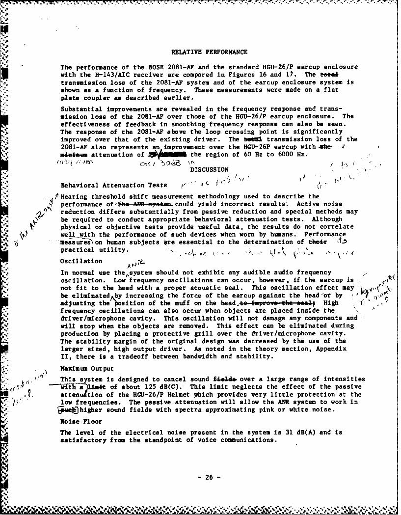
RELATIVE PERFORMANCE
The performance of the BOSE 2081-AF and the standard HGU-26/P earcup enclosurewith the H-143/AIC receiver are compared in Figures 16 and 17. The tete4transmission loss of the 2081-AF system and of the earcup enclosure system isshown as a function of frequency. These measurements were made on a flatplate coupler as described earlier.
Substantial improvements are revealed in the frequency response and trans-mission loss of the 2081-AF over those of the HGU-26/P earcup enclosure. Theeffectiveness of feedback in smoothing frequency response can also be seen.The response of the 2081-AF above the loop crossing point is significantlyimproved over that of the existing driver. The bet transmission loss of the2081-AF also represents an improvement over the HGU-26P earcup with *he-minist attenuation of 1 the region of 60 Hz to 6000 Hz.
DISCUSSION
Behavioral Attenuation Tests i L " i
SHearing threshold shift measurement methodology used to describe theperformance of .he-AR s. tem- could yield incorrect results . Active noisereduction differs substantially from passive reduction and special methods maybe required to conduct appropriate behavioral attenuation tests. Althoughphysical or objective tests provide useful data, the results do not correlate
":" well with the performance of such devices when worn by humans. Performancemeasureson human subjects are essential to the determination of t#e&er %t5practical utility. - .
Oscillation
In normal use the~system should not exhibit any audible audio frequencyoscillation. Low frequency oscillations can occur, however, if the earcup isnot fit to the head with a proper acoustic seal. This oscillation effect maybe eliminated by increasing the force of the earcup against the head-or by -S.adjusting the osition of the muff on the head.,t i...,.ve the seeiA Highfrequency oscillations can also occur when objects are placed inside thedriver/microphone cavity. This oscillation will not damage any components andwill stop when the objects are removed. This effect can be eliminated duringproduction by placing a protective grill over the driver/microphone cavity.The stability margin of the original design was decreased by the use of thelarger sized, high output driver. As noted in the theory section, AppendixII, there is a tradeoff between bandwidth and stability.
Maximum Output
This system is designed to cancel sound f4..U& over a large range of intensities" ih7f)ttabt of about 125 dB(C). This limit neglects the effect of the passive
attenuation of the HOU-26/P Helmet which provides very little protection at the,, ).; low frequencies. The passive attenuation will allow the ANR system to work in
9k*Jhhigher sound fields with spectra approximating pink or white noise.
Noise Floor
The level of the electrical noise present in the system is 31 dB(A) and is
satisfactory from the standpoint of voice communications.
-26-
_%r.5,
-.54 ... 1-.. £ Z . % . . ...- "' . .. .. ,

q.
4U)00
ad~
I _ _ _ _. _ _
_______ __ __ a.__ -LU 0
a. _ _ _ _ _ _ _ _ _27

r -_________ ________
_ _ _ _I_0-10
C 4
.. 0 td
00
"- J Iii to
:% 0
In CY
LL 0
LN vA LALA
- - : a. Ci ') 0) .
-28 -

-7- ---. p -- r . 1 - - I . - 1
REOOMMENDATIONS
There are always unanswered questions and topics for further exploration withany research and development. In this program, several areas could be pursuedto determine the ultimate suitability of active noise reduction for airborneenvironments.
The concept of active noise reduction should be adapted to optimize speechIntelligibility. This ANR system converted existing technology to form aprototype system to determine its feasibility for Air Force use. It wasoptimized for improved hearing protection and not for speech intelligibility.Intelligibility improvements can be obtained by reducing noise in the speechband, thus creating a more favorable speech-to-noise ratio. It would beprudent to examine how the ANR system response can be moved up in frequencyand if such a move did improve intelligibility.
Field testing of the 2081-AF should be performed to evaluate its performanceunder realistic conditions. Although considerable attention was givenrequirements for field conditions during the design of the prototype,prediction of performance in the field is not reliable. Lessons learned fromfield tests provide a sound basis for designing more advanced models of thesystem.
Analyses should be performed to define the needs for making the devicefieldable in the Air Force. Present military microphones and receivers arenot compatible with the ANR system, consequently some development oftransducers would be required. The development of the ANR system electronicsis not considered a major problem, however to develop the remaining componentsof the system to be compatible with the Air Force requirements is asignificant undertaking.
29 -
""..
-p REFERENCES
1. "USAF Bioenvironmental Noise Data Handbook," AMRL-TR-75-50, Vols. 32, 38,and 51, Aerospace Medical Division, Wright Patterson AFB, September 1975.
2. "Communication in High Level Ambient Noise Fields," Prepared by RCA,Contract DA-36-039-SC-64469, May 1955.
3. "A Study of Proposed Ear Protection Devices for Low Frequency NoiseAttenuation," Patrick Dallosta, Army report AD A009 274, April 1975.
4. "An Active Noise Reduction System for Aircrew Helmets," Peter Wheeler andDavid Rawlinson, NASA Conference Publication 2052, Part II, May 1978.
5. "Active Ear Defender Systems: Development of a Laboratory Model," Willard.. Meeker, AF Contract AF 33 (616)-3051, December 1959.
6. "Electronic Control of Noise, Vibration, and Reverberation," Harry Olson,JASA V. 28, N. 5 September 1956.
%'
-. 3
.5 3
.-
V . Q .. . . .
U' e' , , ... e.:.'." ._.'. .. ;...".-.":. '."".."..,." ,""."-". "."-"-- ' - . .. ',.'.-"'
S " '' . L .-L " .-? - ,
", ,, ., " , , ,' - ° -* A"- , , , ' ,' ,".',, , ',,"
,,

APPENDIX I -USER'S GUIDE
This section describes the operation of the 2081-AF prototype. Included is adetailed outline of jacks, connectors, and switch functions and an explanationof a testing procedure. Figure 7 displays front and rear panel layouts. Theacoustical package utilized inside the HGU-26/P ear muff is displayed inFigure 4. Figure 18 diagrams the connectors.
Switch Functions
Noise Cancel: Turns off-and-on noise
cancellation feature. Whenthe switch is in the offposition, the communicationsignal, if present, has afrequency response such thatit will sound the same aswhen the switch is in the onposition. This switch allows
one to experience the effectof noise cancellation alone
on a communication signal.
Power: Connects AC Power to Power
Supply.
Connectors:
Headphone: A keyed circular connectorwhich contains cables goingto the headphone drivers andthe servo microphones.
Audio Input: Line level input for speechcommunication utilizes AFsupplied plug for thispurpose.
Indicators:
Power: Indicates that power is onand 15V supply is active.
Miscellaneous:
Fuse: Use 1/4 amp fast blow fusewhich is inside the powersupply enclosure. Makecertain the unit is dis-connected before replacingfuse. An Allen wrench is
needed to remove the cover.
31

w
L 21*v 0
4 W6
Z UI"-
fmwmqa~ .4
zA r. 44
I.I
I r0
Z000
6534M 40
.5..z
w w W
luium~oo e0
23

APPENDIX II - THEORY OF DESIGN
The Active Noise Reduction System is a Servo System that is composed ofelectrical, mechanical, and acoustical elements. A generalized block diagramof a closed loop noise reduction system is shown in Figure 19.
ACOuSTICNOISEp.
SIGNAL*
!G,%NPuT -- EA R
FEEDBA CK
S,GNAL
Figure 19. Block Diagram of a Closed Loop Noise Reduction System.
From this block diagram, two transfer functions are derived. One is fromreference to output, and the second is from acoustical noise to output. Thereference is the input to the system and typically would be connected to aspeech communication signal. Both of these will be derived for the closedloop configuration and the open loop configuration. Neglecting the noise forthe moment, it can be seen that the block diagram represents a standard servosystem with the transfer fuction:
(1) Output - G (closed loop)Reference 1 + GH
and if the feedback path is broken:
(2) Output " G (open loop)Reference
%4.
-33-
-- %.a. . . • . . . . . . . . .. ..

To derive the gain from noise input to output, the block diagram can be
redrawn as shown in Figure 20.
INP UT EARSIGNAL
3
(INPUT SIGNAL SET TO ZERO)
Figure 20. Block Diagram of a Closed Loop Noise Reduction SystemTreating Noise as the Input.
The ratio of output to noise input has a similar form as the ratio of outputto reference. By noticiing that the forward gain is unity, and the feedbackis now GH, the transfer function is:
(3) Output 1 1 (closed loop)Noise 1 + GH
If the feedback path is broken, the following results:
(4) Output = 1 (open loop)Noise
.
-34 -
-

By taking the ratio, the amount of noise reduction can be derived:
(5) OutputNoise Closed Loop Output
= Closed Loop 1Output Output 1 + GHNoise Open Loop Open Loop
Thus, it can be seen that the noise reduction of this system is 1 + GH, or forhigh loop gains, equal to the open loop gain. Equation (1) becomes with unitygain feedback (H-1) and high gain:
(6) Output G C G 1Reference 1 + GH 1 + G
Equation says that for high gain and unity gain feedback, which are bothtypical for the active noise reduction system, the frequency response will beflat from input to output. This means that the feedback system willcompensate for response irregularities in the driver/ear cup transferfunction. This is discussed further in the "Electroacoustic Performance andEngineering Specifications" section.
The theory of operation of the prototype can be decribed by referring toFigure 21.
O R I vE R MICR OPHONEINPUT POWE F%
SUMMER COMPENSATION AMPLIFIER I--
M•IC10 .ONEPREAMPLIFiER
Figure 21. Block Diagram of a BOSE 2081-AP Active NoiseReduction System.
35
.
~- 35 -

p.I'.
'pp*
When the ear sa s the same pressure as the microphone, then the signal at
the ear is reduced by 1 + GH when the system is activated. Since this is alinear system, the components of operation are additive. Therefore, activenoise reduction will occur even while there is an input (or referencesignal). Furthermore, since passive attenuation operates to reduce thepressure at the ear, the effects of passive and active transmission loss canbe added. Thus, active attenuation can be used to compliment passiveattenuation to provide high overall attenuation at low frequencies.
There are certain other considerations which impact performance because thisis a feedback system. Probably the most important is stability of thefeedback loop. By marginal design, it is possible to create an instabilitywhich will create oscillation. This will occur when the gain is 1 and thereis 1800 of phase shift in the loop. If the phase margin is increased, theloop will not oscillate, but it is possible to have peaking of the response.
This peaking has two side effects; first, it causes noise enhancement becausethe magnitude of the noise reduction function 1 + GH is now less than 1.
Second, it causes the closed loop response to have a peak in the frequencyresponse which may impair speech quality. There is a tradeoff in loopbandwidth and stability. Since there is a time delay in the system (from thedriver to the microphone) the loop bandwidth cannot be extended indefinitely.As the bandwidth is extended the phase, due to the time delay, is increased.Since the phase affects stability, the time delay imposes a fundamentallimitation on system performance.
The prototype supplied suffers to some extent from oscillation because it wasdesired to both meet the original noise cancellation specifications andutilize a larger driver with higher output capability. In order to reduce thepossibility of oscillation, the diameter of the, e can be reduced tominimize time elay. Alternately, the gain of the system can be reduced.
64-
-36 -
* a . -" a -' , ,-. .' Z ' .," -"- , .' . . . . . . .. . . . . " ". . . ' - ' "
a.. t= ' r , l r, , , ,", , . .'t ; .. :., . . . . . . . ' . . . . . . , , ,.

"-AA- 4
Sr 4, 1rik. 4
4Cb?$ tW'
II.
it A4
, s- ;i4
eit - F4..
- 144ir'AA'
W 1'' ' 4


!['I, l?n?o 0 l-lDDt I J … · Ill llllllllllllllllllll II II Ill II IIIIII II Im 11111111111 IIIIII Ill lml 1111111 El lfJ\\l .t-WIIIJtl. p ., [ _] 77741105 6516 A1LKSA WED -08 JAN](https://static.fdocuments.us/doc/165x107/6064104134f53859934033fb/i-lno-0-l-lddt-i-j-ill-llllllllllllllllllll-ii-ii-ill-ii-iiiiii-ii-im-11111111111.jpg)