Iii avr-basics(2)
40
Microprocessor based Design for Biomedical Applications MBE 3 – MDBA III : The ATmega8 Basic Features (2)
-
Upload
billy-alwarfally -
Category
Engineering
-
view
20 -
download
1
Transcript of Iii avr-basics(2)

Microprocessor based Design for Biomedical Applications
MBE 3 – MDBA
III : The ATmega8 Basic Features (2)

Let‘s repeat some important topics of the last lecture:
AVR memoriesSFRs – GFRsBit OperationsGPIO PortsClock SourcesInterrupt Handling

Today:
Fix the IDE – Bug (update AVR-Studio)Repeat blink.c sourceUse the SimulatorLook at avr-gcc, avr-objdump, make ISR – Interrupt Service RoutinesTimer Interrupt Example16-Bit Timer, ModesUART – Configuration and ModesStart with Uart Example

Blink.c – sourcecode review
#include <avr/io.h> #include <util/delay_basic.h>
#define Bit(x) (1<<x)
void delay_ms(uint16_t ms){ uint16_t t; for (t=0;t<ms;t++) _delay_loop_2(1843); // 1843 * 4 clock cycles gives 7372 cycles: // (approx. 1 millisecond at 7,3728 MHz}
int main( void ){ DDRD = Bit(5); // DataDirection Port D: Pin D5 = Output (Led) PORTD= Bit(5); // Switch on led and deactivate pullups on the inputs
while (1) { PORTD ^= Bit(5); // toggle D5 delay_ms(500); // wait 500 milliseconds }return(0);}
Macro definition, shift left operation
Function definition, call by value (call by reference: pointer)
SFRs for Port D configuration
Bit manipulation Port D (XOR)
Include device specific definitions (SFRs,..)

Using the AVRStudio - Simulator
additional information to the Getting_Started.pdf
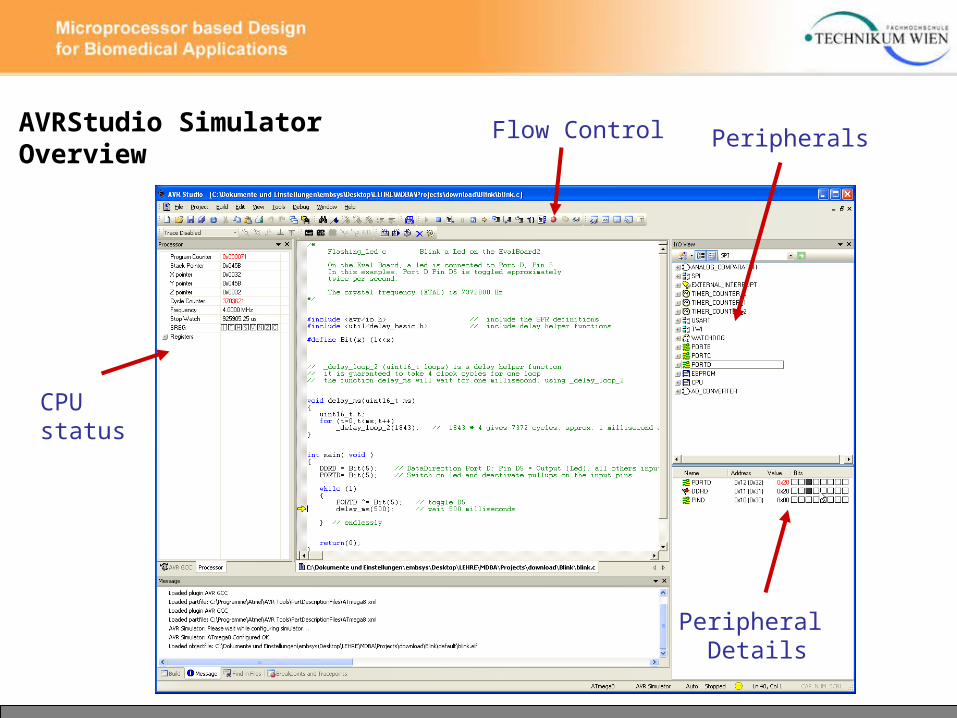
Flow Control Peripherals
Peripheral Details
CPUstatus
AVRStudio SimulatorOverview

AVRStudio SimulatorOverview
Breakpoint
Watch Window

AVRStudio SimulatorOverview
Register and Memory Views
Watch Window
Disassembly Window

AVRStudio Simulator notes
● Select the Crystal / Oscillator frequency to get accurate time measurements in the Simulator
● beware of delay loops (they take long to simulate)
● use „run to cursor“ or breakpoints for getting into interrupt handlers
● on-chip debugging is useful, needs devices with JTAG interface or debugWire interface

Using the WinAVR-Toolchain from commandline

WinAVR-Toolchain – avr-gcc.exe
Compile
Link
Convert .elf to .ihex
Download to Device
.elf: Executable and Linking Format, segment and section information

WinAVR-Toolchain – make.exeMAKEFILE The makefile automates the build process only changed modules are compiled
Environment variables add flexibility
current target
current prerequistite
Browse the GNU MAKE User Manual: http://www.gnu.org/software/make
Rules
Variables & constants
Target
SRC = blink.c test.cCFLAGS= -O2 -g -Wall
PRG = $(SRC:.c=.hex)
all: $(PRG)
# Create .hex files from .o files%.hex : %.o
echo Creating $@avr-objcopy -O ihex $< $@
# Compile%.o : %.c
echo Compiling $@avr-gcc $(CFLAGS) -mmcu=atmega8 $< -o $@
clean:rm -f *~ *.bak *.lst *.o *.hexc
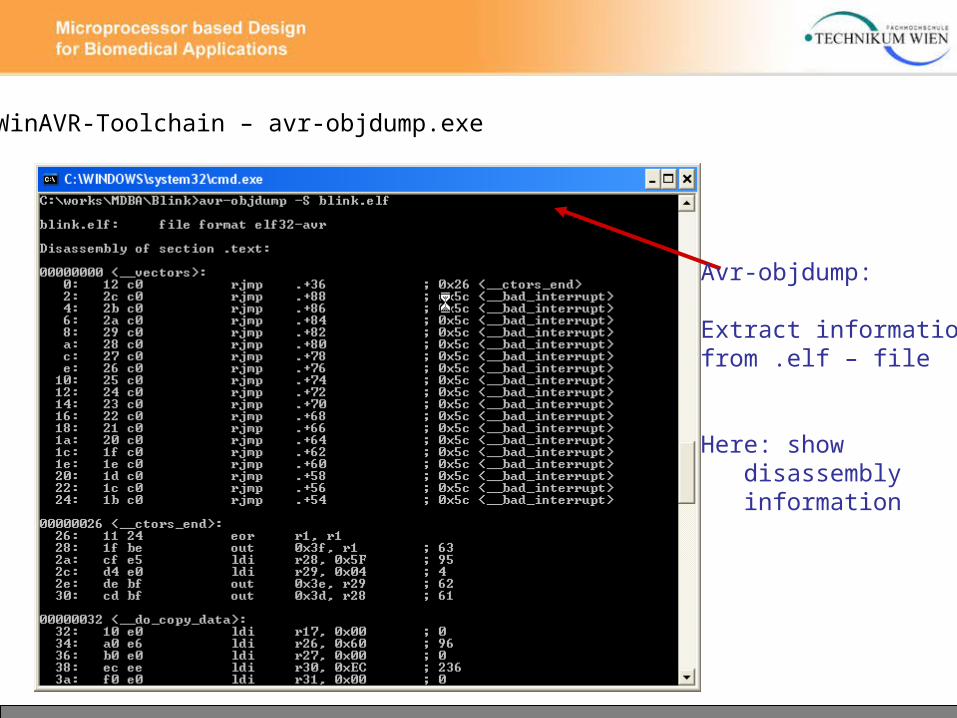
WinAVR-Toolchain – avr-objdump.exe
Avr-objdump:
Extract informationfrom .elf – file
Here: show disassembly information

Where to find AVR C - specific information ?
● AVR-GCC is ANSI-C compatible
● browse the AVR Libc – Documentation
● examine module header files (#include <…>) subdirectory avr/include
● use example code, play with open source firmware
Where to find AVR C - specific information ?
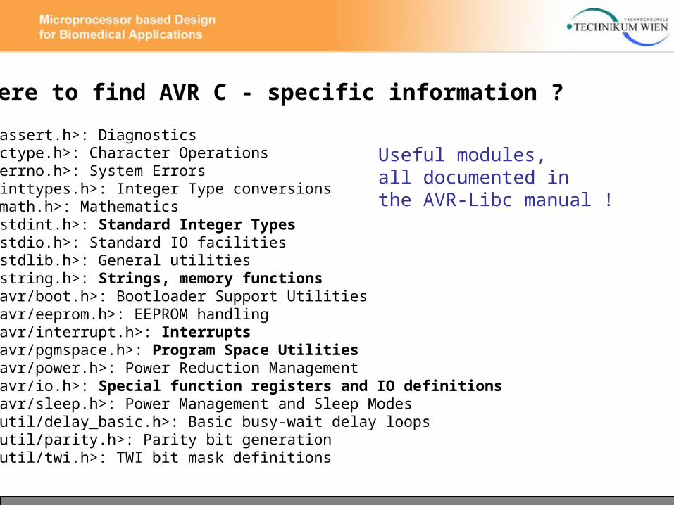
<assert.h>: Diagnostics <ctype.h>: Character Operations <errno.h>: System Errors <inttypes.h>: Integer Type conversions <math.h>: Mathematics <stdint.h>: Standard Integer Types <stdio.h>: Standard IO facilities <stdlib.h>: General utilities <string.h>: Strings, memory functions<avr/boot.h>: Bootloader Support Utilities <avr/eeprom.h>: EEPROM handling <avr/interrupt.h>: Interrupts <avr/pgmspace.h>: Program Space Utilities<avr/power.h>: Power Reduction Management<avr/io.h>: Special function registers and IO definitions<avr/sleep.h>: Power Management and Sleep Modes<util/delay_basic.h>: Basic busy-wait delay loops <util/parity.h>: Parity bit generation<util/twi.h>: TWI bit mask definitions
Useful modules,all documented inthe AVR-Libc manual !

Where to find AVR C - specific information ?
• typedef signed char int8_t• typedef unsigned char uint8_t• typedef signed int int16_t• typedef unsigned int uint16_t• typedef signed long int int32_t• typedef unsigned long int uint32_t• typedef signed long long int int64_t• typedef unsigned long long int uint64_t
#define INT8_MAX 0x7f#define INT8_MIN (-INT8_MAX - 1)
…
Standard integer and character types, defined in <stdint.h>: 8, 16, 32 and 64 bit, signed and unsigned
Constants for min and max values

Where to find AVR C - specific information ?
• void memcpy (void , const void , size_t)• void memmove (void , const void , size_t)• char strcat (char , const char )• char strstr (const char , const char )• char strupr (char )…
Some functions from <string.h>:

Interrupt handling with the AVR-Libc API
Interrupt and Signal definitions: <avr/interrupt.h>
● remember: vector table points to interrupt routines
● by using the appropriate name, your routine will be installed in the table and called when the interrupt occurs
● a set of default interrupt routines is provided
● Macro for registering interrupt routines: ISR (<signalname>)
● saving and restoring registers is handled

Interrupt handling with the AVR-Libc API
Examle interrupt handler for the ADC:
#include <avr/interrupt.h>
ISR(ADC_vect) { // user code here } ● The interrupt source, here the ADC, has to be configured and enabled using SFRs
● Global interrupt instructions: sei () … set interupt enable (I – bit in SREG) cli () … clear interrupt enable
● AVR hardware clears the global interrupt flag before entering an interrupt vector -> use sei() to enable nested interrupts

Interrupt handling with the AVR-Libc API
Useful Interrupt vector names for ATmega8:
ADC_vect analog/digital converter ANA_COMP_vect analog comparator EE_RDY_vect eeprom ready INT0_vect external interrupt 0 TIMER0_OVF_vect Timer0 overflow event TIMER1_CAPT_vect Timer1 capture event SPI_STC_vect serial transfer complete USART_UDRE_vect USART data register empty USART_RXC_vect USART receive complete

more AVR Peripheral Features

16 – bit Timer / Counter 1
● Two Independent Output Compare Units● can be used as Pulse Width Modulator (PWM)● Clear Timer on Compare Match (Auto Reload)● One Input Capture Unit● can be used as External Event Counter● Four Independent Interrupt Sources TOV1, OCF1A, OCF1B, and ICF1

16 – bit Timer / Counter 1
● TCNT1, OCR1A, OCR1B and ICR1 are 16-bit registers
● write high byte first read low byte first (automatically done in C)
● clocking via prescaler or external clock on pin T1
● output compare register OCR1A/B can be used for PWM generation (output pin: OC1A/B) or for interrupt request

16 – bit Timer / Counter 1
● Input capture Unit: timestamp external events on ICP1 pin (or on Analog comp.) Can generate Input Capture Interrupt

16 – bit Timer / Counter 1
● Output Compare Units: compare TCNT1 with OCR1A and OCR1B Can generate Output Capture Interrupt
● 13 PWM / Waveform generation modes
● Top and Bottom values
● Auto reload

16 – bit Timer / Counter 1
● Mode configuration using TCCR1A and TCCR1B
PWM Mode, set/clear/toggle of OC1A/B, auto-reload, Noise canceller
Find Details in the ATmega8 datasheet !

16 – bit Timer / Counter 1
● Clock source configuration using TCCR1B

The UART Serial Interface

USART interface
● universal synchronous / asynchronous receiver / transmitter
● Full Duplex Operation: Receive and Transmit Registers
● Asynchronous or Synchronous Operation
● Frames with 5, 6, 7, 8, or 9 Databits and 1 or 2 Stop Bits
● Odd or Even Parity Generation and Parity Check
● Framing Error Detection, Noise Filtering
● Interrupts possible on TX Complete, TX Data Register Empty and RX Complete

USART interface
● synchronous mode: Pin XCK is used as clock Input (slave) or clock output (master)
● asynchronous mode: receiver and transmitter are clocked independently

USART interface
● Frame formats:

USART interface
● calculating the baud rate register value:
low and high byte of ubrr are written into the UBRRL and UBRRH registers
Accuracy depends on System clock source !
(see table in ATmega8 data sheet, pp 155)

USART interface
● Initialisation: set baud rate, frame format, enable TX and RX
RXC: RX completeTXC: TX completeUDR: Uart Data Register emptyFE: Frame ErrorDOR: Data OverRunPE: Parity ErrorU2X: Double the USART speed

USART interface
● Initialisation: set baud rate, frame format, enable TX and RX
RXCIE: RX complete interrupt enableTXCIE: TX complete interrupt enableUDRIE: Uart Data Register empty interrupt enableRXEN: Receiver EnableTXEN: Transmitter EnableUCSZ2: Character SizeRXB8, TXB8: Bit 8 for receive and transmit
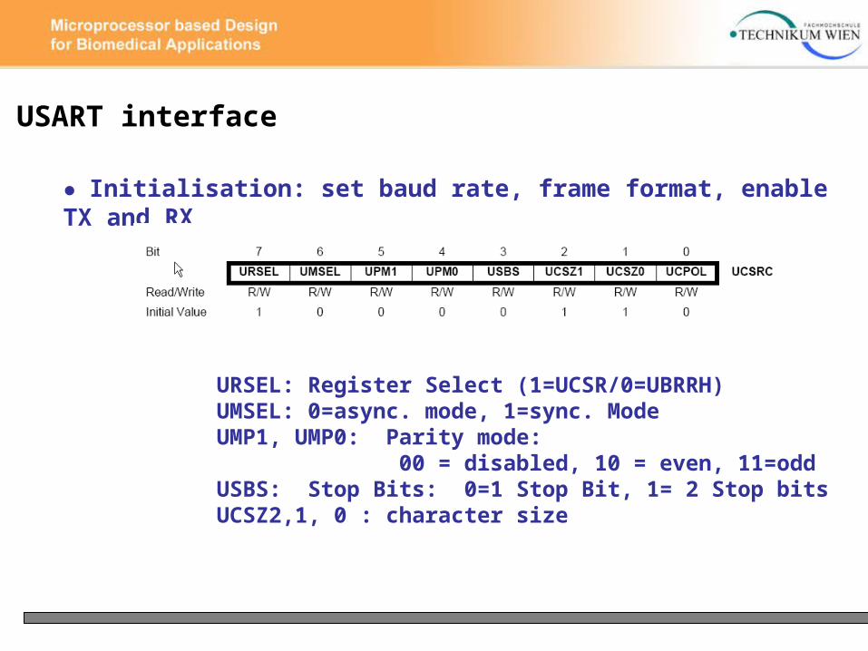
USART interface
● Initialisation: set baud rate, frame format, enable TX and RX
URSEL: Register Select (1=UCSR/0=UBRRH)UMSEL: 0=async. mode, 1=sync. ModeUMP1, UMP0: Parity mode: 00 = disabled, 10 = even, 11=oddUSBS: Stop Bits: 0=1 Stop Bit, 1= 2 Stop bitsUCSZ2,1, 0 : character size

USART interface
character size selection using the UCSZ bits

USART interface
Selection of the baud rate using the UBRRH and UBRRL SFRs:
URSEL has to be 0 when writing to the UBRRH register
USART interface
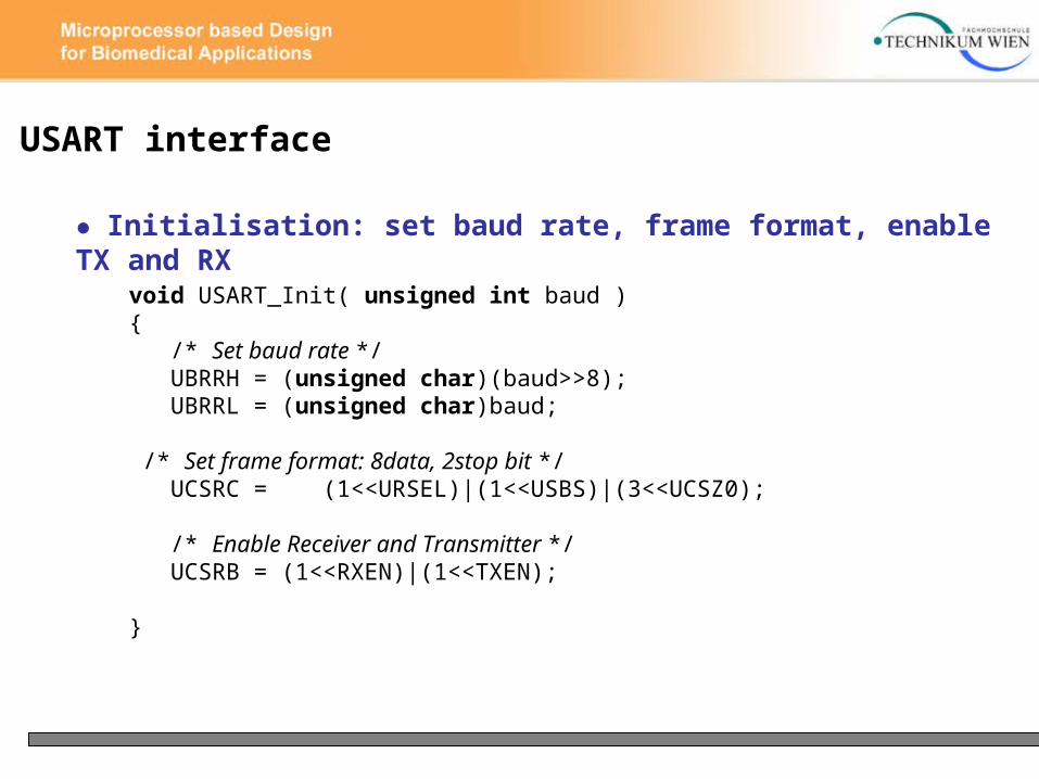
● Initialisation: set baud rate, frame format, enable TX and RX
void USART_Init( unsigned int baud ){ /* Set baud rate */ UBRRH = (unsigned char)(baud>>8); UBRRL = (unsigned char)baud;
/* Set frame format: 8data, 2stop bit */ UCSRC = (1<<URSEL)|(1<<USBS)|(3<<UCSZ0);
/* Enable Receiver and Transmitter */ UCSRB = (1<<RXEN)|(1<<TXEN);
}
USART interface
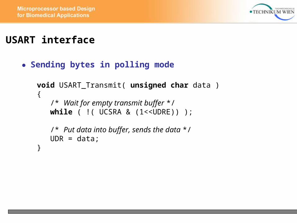
● Sending bytes in polling mode
void USART_Transmit( unsigned char data ){ /* Wait for empty transmit buffer */ while ( !( UCSRA & (1<<UDRE)) );
/* Put data into buffer, sends the data */ UDR = data;}

USART interface
● Receiving bytes in polling mode
unsigned char USART_Receive( void ){ /* Wait for data to be received */ while ( !(UCSRA & (1<<RXC)) ) ;
/* Get and return received data from buffer */ return UDR;}