IFR 6000 Manual
254
Test Set Operation Manual IFR 6000 TCAS/ADS-B/TIS XPDR/DME Issue 7 EXPORT CONTROL WARNING: This document contains controlled technology or technical data under the jurisdiction of the Export Administration Regulations (EAR), 15 CFR 730-774. It cannot be transferred to any foreign third party without the specific prior approval of the U.S. Department of Commerce Bureau of Industry and Security BIS). Violations of these regulations are punishable by fine, imprisonment, or both.
description
maintenance Manual ifr 6000
Transcript of IFR 6000 Manual

Test Set
Operation Manual IFR 6000
TCAS/ADS-B/TISXPDR/DME
Issue 7
EXPORT CONTROL WARNING: This document contains controlled technology or technical data under the jurisdiction of the Export Administration Regulations (EAR), 15 CFR 730-774. It cannot be transferred to any foreign third party without the specific prior approval of the U.S. Department of Commerce Bureau of Industry and Security BIS). Violations of these regulations are punishable byfine, imprisonment, or both.
Subject to Export Control , see Cover Page for deta i ls .
OPERATION MANUAL
XPDR/DME/TCAS/ADS-B/TIS
TEST SET
IFR 6000
PUBLISHED BY Aerof lex
COPYRIGHT © Aerof lex 2009 Al l r ights reserved. No par t o f th is publ icat ion may be reproduced, s tored in a re t r ieva l system, or t ransmi t ted in any form or by any means, e lec t ron ic , mechanica l , photocopying, record ing or o therwise wi thout the pr ior permiss ion of the publ isher .
Or ig ina l Pr in t ing Mar 2005
Issue 2 Sep 2005
Issue 3 Nov 2005
Issue 4 Jan 2006
Issue 5 Aug 2007
Issue 6 Dec 2007
Issue 7 Dec 2009
10200 West York / Wich i ta , Kansas 67215 U.S.A. / (316) 522-4981 / FAX (316) 524-2623
OPERATION MANUAL IFR 6000
Subject to Export Control , see Cover Page for deta i ls .
THIS PAGE INTENTIONALLY LEFT BLANK.

OPERATION MANUAL IFR 6000
Subject to Export Control , see Cover Page for deta i ls .
Cable Statement:
For cont inued EMC compl iance, a l l external cables must be double sh ie lded.
For cont inued EMC compl iance, a l l external cables must be 3 meters or less in length.
Nomenclature Statement:
In th is manual Test Set or Uni t re fers to the IFR 6000 XPDR/DME/TCAS/ADS-B/TIS B Test Set .

OPERATION MANUAL IFR 6000
Subject to Export Control , see Cover Page for deta i ls .
THIS PAGE INTENTIONALLY LEFT BLANK.

OPERATION MANUAL IFR 6000
Subject to Export Control , see Cover Page for deta i ls .
SAFETY FIRST: TO ALL OPERATIONS PERSONNEL
REFER ALL SERVICING OF UNIT TO QUALIFIED TECHNICAL PERSONNEL. THIS UNIT CONTAINS NO OPERATOR SERVICEABLE PARTS.
WARNING: USING THIS EQUIPMENT IN A MANNER NOT SPECIF IED BY THE ACCOMPANYING DOCUMENTATION MAY IMPAIR THE SAFETY PROTECTION PROVIDED BY THE EQUIPMENT.
CASE, COVER OR PANEL REMOVAL
Opening the Case Assembly exposes the operator to e lec t r i ca l hazards that can resu l t in e lec t r i ca l shock or equ ipment damage. Do not operate th is Tes t Set w i th the Case Assembly open.
SAFETY IDENTIFICATION IN TECHNICAL MANUAL
This manual uses the fo l lowing terms to draw at tent ion to poss ib le safe ty hazards , that may ex is t when operat ing or serv ic ing th is equ ipment .
CAUTION: THIS TERM IDENTIFIES CONDITIONS OR ACTIVIT IES THAT, IF IGNORED, CAN RESULT IN EQUIPMENT OR PROPERTY DAMAGE (E .G. , F IRE) .
WARNING: THIS TERM IDENTIFIES CONDITIONS OR ACTIVIT IES THAT, IF IGNORED, CAN RESULT IN PERSONAL INJURY OR DEATH.
SAFETY SYMBOLS IN MANUALS AND ON UNITS
CAUTION: Refer to accompany ing documents . (Th is symbol re fers to spec i f i c CAUTIONS represented on the un i t and c lar i f ied in the tex t . )
AC OR DC TERMINAL: Termina l that may supp ly or be supp l ied wi th AC or DC vo l tage.
DC TERMINAL: Termina l that may supp ly or be supp l ied wi th DC vo l tage.
AC TERMINAL: Termina l that may supp ly or be supp l ied wi th AC or a l te rnat ing vo l tage.
EQUIPMENT GROUNDING PRECAUTION
Improper ground ing o f equ ipment can resu l t in e lec t r i ca l shock .
USE OF PROBES
Check the spec i f i ca t ions for the max imum vo l tage, cur rent and power ra t ings o f any connec tor on the Tes t Set before connec t ing i t w i th a probe f rom a termina l dev ice. Be sure the termina l dev ice per forms wi th in these spec i f i ca t ions before us ing i t fo r measurement , to prevent e lec t r i ca l shock or damage to the equ ipment .
POWER CORDS
Power cords mus t not be f rayed, broken nor expose bare wi r ing when operat ing th is equ ipment .
USE RECOMMENDED FUSES ONLY
Use on ly fuses spec i f i ca l l y recommended for the equ ipment a t the spec i f ied cur rent and vo l tage ra t ings .
INTERNAL BATTERY
This un i t conta ins a L i th ium Ion Bat tery , serv iceab le on ly by a qua l i f ied techn ic ian.
CAUTION: S IGNAL GENERATORS CAN BE A SOURCE OF ELECTROMAGNETIC INTERFERENCE (EMI ) TO COMMUNICATION RECEIVERS. SOME TRANSMITTED SIGNALS CAN CAUSE DISRUPTION AND INTERFERENCE TO COMMUNICATION SERVICES OUT TO A DISTANCE OF SEVERAL MILES. USERS OF THIS EQUIPMENT SHOULD SCRUTINIZE ANY OPERATION THAT RESULTS IN RADIATION OF A S IGNAL (DIRECTLY OR INDIRECTLY) AND SHOULD TAKE NECESSARY PRECAUTIONS TO AVOID POTENTIAL COMMUNICATION INTERFERENCE PROBLEMS.

OPERATION MANUAL IFR 6000
Subject to Export Control , see Cover Page for deta i ls .
THIS PAGE INTENTIONALLY LEFT BLANK.
OPERATION MANUAL IFR 6000
Subject to Export Control , see Cover Page for deta i ls .
DECLARATION OF CONFORMITY
The Declaration of Conformity Certif icate included with the Unit should remain with the Unit. Aeroflex recommends the operator reproduce a copy of the Declaration of Conformity Certif icate to be stored with the Operation Manual for future reference.

OPERATION MANUAL IFR 6000
Subject to Export Control , see Cover Page for deta i ls .
THIS PAGE INTENTIONALLY LEFT BLANK.

OPERATION MANUAL IFR 6000
TABLE OF CONTENTS Subject to Export Control , see Cover Page for deta i ls . Page 1
Dec 1/09
TABLE OF CONTENTS
Ti t le Chapter /Sect ion
T i t le Page / Copyr ight Page Statements Safety Page Declarat ion of Conformi ty Table of Contents In t roduct ion Serv ice Upon Receipt o f Mater ia l
Chapter 1
Sect ion 1 - Descr ip t ion and Quick Star t 1-1 Sect ion 2 - Operat ion 1-2 Sect ion 3 - Speci f icat ions 1-3 Sect ion 4 - Shipp ing 1-4 Sect ion 5 - Storage 1-5
Appendix A - Connector P in-Out Tables Appendix B - Metr ic /Br i t ish Imper ia l Convers ion Table wi th Naut ica l Dis tance Convers ions Appendix C - Factory /Power Up Presets Appendix D - Abbrev iat ions Appendix E - Breakout Box Appendix F - Transponder Conf igurat ions Appendix G - Mode S Address Blocks (Product Speci f ic L is t ) Appendix H - Mode S Address Blocks (Complete L is t ) Appendix I - S ignal Formats Appendix J - Standard Accessor ies Appendix K - Target Acquis i t ion T ime Probabi l i ty Table
Index
Bat tery /Fuse Inst ruct ions

OPERATION MANUAL IFR 6000
TABLE OF CONTENTS Subject to Export Control , see Cover Page for deta i ls . Page 2
Dec 1/09
THIS PAGE INTENTIONALLY LEFT BLANK.

OPERATION MANUAL IFR 6000
INTRODUCTION Subject to Export Control , see Cover Page for deta i ls . Page 1
Dec 1/09
INTRODUCTION
This manual conta ins operat ing inst ruct ions fo r the IFR 6000. I t is s t rongly recommended that personnel be thoroughly fami l iar wi th the contents of th is manual before at tempt ing to operate th is equipment .
Refer a l l serv ic ing of un i t to qual i f ied technica l personnel .
ORGANIZATION
This manual is d iv ided in to the fo l lowing Chapters and Sect ions:
CHAPTER 1 - OPERATION
Sect ion 1 - DESCRIPTION and Quick Star t ( for operators fami l iar wi th av ion ics systems)
Sect ion 2 - OPERATION ( insta l la t ion, descr ip t ion of cont ro ls , connectors and ind icators , per formance evaluat ion and operat ing procedures)
Sect ion 3 - SPECIFICATIONS
Sect ion 4 - SHIPPING
Sect ion 5 - STORAGE
OPERATION MANUAL IFR 6000
INTRODUCTION Subject to Export Control , see Cover Page for deta i ls . Page 2
Dec 1/09
THIS PAGE INTENTIONALLY LEFT BLANK.

OPERATION MANUAL IFR 6000
1-TABLE OF CONTENTS Subject to Export Control , see Cover Page for deta i ls . Page 1
Dec 1/09
CHAPTER ONE
IFR 6000 XPDR/DME/TCAS/ADS-B/TIS/TIS-B TEST SET
OPERATION MANUAL
TABLE OF CONTENTS
T i t le Chapter /Sect ion/Subject Page
SECTION 1 - DESCRIPTION 1-1
1. Genera l Descr ip t ion and Capabi l i t ies 1-1-1 1 1 .1 Descr ip t ion 1-1-1 1 1 .2 Funct ional Capabi l i t ies 1-1-1 1 1 .3 Regulatory Responsib i l i t ies 1-1-1 2 2. Quick Star t 1-1-2 1 2 .1 Contro ls 1-1-2 1 2 .2 Genera l Setup 1-1-2 2 2 .3 XPDR Setup Over the Ai r 1-1-2 2 2 .4 XPDR Setup Di rect Connect 1-1-2 4 2 .5 XPDR Test ing 1-1-2 5 2 .5.1 ADS-B/GICB Test ing 1-1-2 6 2 .5.1.1 ADS-B MON 1-1-2 6 2 .5.1.2 ADS-B GEN 1-1-2 7 2 .5 .1.2 GICB 1-1-2 8 2 .6 DME Setup Antenna 1-1-2 8 2 .7 DME Setup Di rect Connect 1-1-2 9 2 .8 DME Test ing 1-1-2 9 2 .9 TCAS Setup Antenna 1-1-2 10 2 .10 TCAS Test ing 1-1-2 11 2 .11 TIS Setup Antenna 1-1-2 12 2 .12 TIS Setup Di rect Connect 1-1-2 13 2 .13 TIS Test ing 1-1-2 13
SECTION 2 - OPERATION 1-2
1. Insta l la t ion 1-2-1 1 1 .1 Genera l 1-2-1 1 1 .2 Bat tery Operat ion 1-2-1 1 1 .3 Bat tery Charg ing 1-2-1 1 1 .4 Safety Precaut ions 1-2-1 1
1.4.1 Comply ing wi th Inst ruct ions 1-2-1 1 1.4.2 Grounding Power Cord 1-2-1 1 1.4.3 Operat ing Safety 1-2-1 1
1 .5 AC Power Requi rements 1-2-1 2 1 .6 Bat tery Recharg ing 1-2-1 2 1 .7 External Cleaning 1-2-1 3 2. Contro ls , Connectors and Ind icators 1-2-2 1 3. Per formance Evaluat ion 1-2-3 1 3 .1 Genera l 1-2-3 1 3 .2 Sel f Test 1-2-3 1 4. Operat ing Procedures 1-2-4 1 4 .1 Genera l 1-2-4 1 4 .2 Star t -Up 1-2-4 2

OPERATION MANUAL IFR 6000
1-TABLE OF CONTENTS Subject to Export Control , see Cover Page for deta i ls . Page 2
Dec 1/09
TABLE OF CONTENTS (cont)
Ti t le Chapter /Sect ion/Subject Page
SECTION 2 – OPERATION (cont) 1-2
4 .3 XPDR (Transponder) 1-2-4 2 4.3.1 Conf igurat ions 1-2-4 2 4.3.2 Setup 1-2-4 3 4.3.3 Auto Test 1-2-4 8 4.3.4 Test L is t 1-2-4 10 4.3.5 Al t i tude Encoder 1-2-4 28 4.3.6 Di rect Connect Procedure 1-2-4 29 4.3.7 “Over the Ai r ” Ground Test 1-2-4 29 4.3.8 “Over the Ai r ” S imulated Al t i tude Test 1-2-4 30
4 .4 DME 1-2-4 30 4.4.1 Setup 1-2-4 32
4 .5 TCAS Mode 1-2-4 35 4.5.1 TCAS Operat ion Concept 1-2-4 35 4.5.2 TCAS Test ing 1-2-4 38 4.5.3 TCAS Setup 1-2-4 38 4.5.4 TCAS Screen 1-2-4 42 4.5.5 Setup-Scenar io Data Screen 1-2-4 45 4.5.6 Moni tor Screens 1-2-4 47 4 .5.6.1 Survei l lance Moni tor 1-2-4 47 4 .5.6.2 Broadcast Moni tor 1-2-4 49 4 .5.6.3 ATCRBS 1-2-4 51 4.5.7 Recommended Test Procedure 1-2-4 54
4 .6 ADS-B Genera l 1-2-4 56 4.6.1 ADS-B/GICB Modes 1-2-4 56 4.6.2 Setup ADS-B 1-2-4 56 4.6.3 ADS-B/GICB MAIN 1-2-4 58 4.6.4 ADS-B MON 1-2-4 58 4.6.5 ADS-B GEN 1-2-4 68 4.6.6 GICB General 1-2-4 76 4.6.7 GICB Mode 1-2-4 76
4.7 TIS General 1-2-4 97 4.7.1 TIS Mode 1-2-4 97 4.7.2 TIS Setup 1-2-4 97 4.8 Di rect ional Antenna 1-2-4 101 4.9 Breakout Box 1-2-4 105 SECTION 3 - SPECIFICATIONS 1-3
SECTION 4 - SHIPPING 1-4
1. Shipping Test Sets 1-4-1 1 1 .1 In format ion 1-4-1 1 1 .2 Repacking Procedure 1-4-1 1
SECTION 5 - STORAGE 1-5

OPERATION MANUAL IFR 6000
1-LIST OF ILLUSTRATIONS Subject to Export Control , see Cover Page for deta i ls . Page 1
Dec 1/09
LIST OF ILLUSTRATIONS
Ti t le Chapter /Sect ion/Subject Page
Contro ls 1-1-2 1 Sof t Keys 1-1-2 1 DATA Keys 1-1-2 1 Genera l Setup Screen 1-1-2 2 Antenna Mount ing 1-1-2 2 Ramp Test ing 1-1-2 3 XPDR SETUP Screen 1-1-2 3 XPDR CONFIG Screen 1-1-2 5 XPDR AUTO Test Screen 1-1-2 5 XPDR Test L is t Screen 1-1-2 5 ADS-B/GICB SETUP Screen 1-1-2 6 ADS-B/GICB MAIN Menu 1-1-2 6 ADS-B GEN Lis t Screen 1-1-2 7 ADS-B MON Lis t Screen 1-1-2 7 ADS-B MON BDS Screen Example 1-1-2 7 GICB L is t Screen 1-1-2 8 GICB BDS Screen Example 1-1-2 8 SETUP-DME Screen 1-1-2 9 DME Test Screen 1-1-2 10 SETUP TCAS Screen 1-1-2 10 TCAS Test Screen 1-1-2 11 SETUP TIS Screen 1-1-2 12 TIS Test Screen 1-1-2 14 Bat tery Recharg ing 1-2-1 2 IFR 6015 Front Panel 1-2-2 1 Di rect ional Antenna 1-2-2 6 Breakout Box, Front V iew 1-2-2 6 Breakout Box, Top View 1-2-2 7 Breakout Box, Bot tom View 1-2-2 7 XPDR Auto Test Screen 1-2-4 2 Conf igurat ions L is t Screen 1-2-4 2 XPDR Informat ion Screen 1-2-4 3 Setup XPDR Screen 1-2-4 3 Setup Genera l Screen 1-2-4 6 Setup Test Data Screen 1-2-4 6 Conf i rm Screen 1-2-4 6 Setup Store Name Screen 1-2-4 7 Auto Test Screen Test Running 1-2-4 8 Auto Test Screen PASS 1-2-4 8 ATCRS Class B Auto Test Screen 1-2-4 10 Gener ic ATCRBS Auto Test Screen 1-2-4 10 XPDR Test L is t Mode S 1-2-4 11 XPDR Test L is t ATCRBS 1-2-4 11 XPDR A/C Decoder /SLS Test Screen 1-2-4 11 XPDR A/C Spacing Width Test Screen 1-2-4 12 Power and Frequency (Mode S) Test Screen 1-2-4 13 Power and Frequency (ATCRBS) Test Screen 1-2-4 13 XPDR - S Al l Cal l Test Screen 1-2-4 15 XPDR - S Reply T iming Test Screen 1-2-4 16 XPDR - S Reply Test Screen 1-2-4 17 UF0 Test Screen 1-2-4 18 UF4 Test Screen 1-2-4 19 UF5 Test Screen 1-2-4 19
OPERATION MANUAL IFR 6000
1-LIST OF ILLUSTRATIONS Subject to Export Control , see Cover Page for deta i ls . Page 2
Dec 1/09
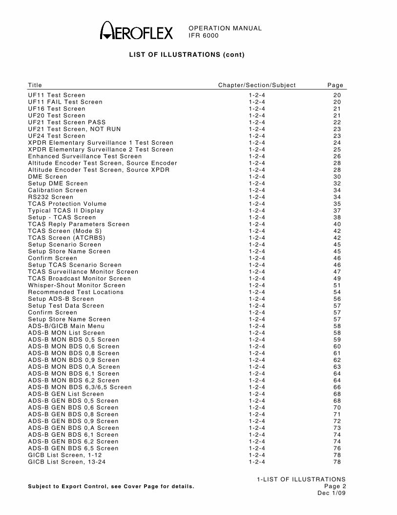
LIST OF ILLUSTRATIONS (cont)
Ti t le Chapter /Sect ion/Subject Page
UF11 Test Screen 1-2-4 20 UF11 FAIL Test Screen 1-2-4 20 UF16 Test Screen 1-2-4 21 UF20 Test Screen 1-2-4 21 UF21 Test Screen PASS 1-2-4 22 UF21 Test Screen, NOT RUN 1-2-4 23 UF24 Test Screen 1-2-4 23 XPDR Elementary Survei l lance 1 Test Screen 1-2-4 24 XPDR Elementary Survei l lance 2 Test Screen 1-2-4 25 Enhanced Survei l lance Test Screen 1-2-4 26 Al t i tude Encoder Test Screen, Source Encoder 1-2-4 28 Al t i tude Encoder Test Screen, Source XPDR 1-2-4 28 DME Screen 1-2-4 30 Setup DME Screen 1-2-4 32 Cal ibrat ion Screen 1-2-4 34 RS232 Screen 1-2-4 34 TCAS Protect ion Volume 1-2-4 35 Typica l TCAS I I Disp lay 1-2-4 37 Setup - TCAS Screen 1-2-4 38 TCAS Reply Parameters Screen 1-2-4 40 TCAS Screen (Mode S) 1-2-4 42 TCAS Screen (ATCRBS) 1-2-4 42 Setup Scenar io Screen 1-2-4 45 Setup Store Name Screen 1-2-4 45 Conf i rm Screen 1-2-4 46 Setup TCAS Scenar io Screen 1-2-4 46 TCAS Survei l lance Moni tor Screen 1-2-4 47 TCAS Broadcast Moni tor Screen 1-2-4 49 Whisper-Shout Moni tor Screen 1-2-4 51 Recommended Test Locat ions 1-2-4 54 Setup ADS-B Screen 1-2-4 56 Setup Test Data Screen 1-2-4 57 Conf i rm Screen 1-2-4 57 Setup Store Name Screen 1-2-4 57 ADS-B/GICB Main Menu 1-2-4 58 ADS-B MON Lis t Screen 1-2-4 58 ADS-B MON BDS 0,5 Screen 1-2-4 59 ADS-B MON BDS 0,6 Screen 1-2-4 60 ADS-B MON BDS 0,8 Screen 1-2-4 61 ADS-B MON BDS 0,9 Screen 1-2-4 62 ADS-B MON BDS 0,A Screen 1-2-4 63 ADS-B MON BDS 6,1 Screen 1-2-4 64 ADS-B MON BDS 6,2 Screen 1-2-4 64 ADS-B MON BDS 6,3/6,5 Screen 1-2-4 66 ADS-B GEN Lis t Screen 1-2-4 68 ADS-B GEN BDS 0,5 Screen 1-2-4 68 ADS-B GEN BDS 0,6 Screen 1-2-4 70 ADS-B GEN BDS 0,8 Screen 1-2-4 71 ADS-B GEN BDS 0,9 Screen 1-2-4 72 ADS-B GEN BDS 0,A Screen 1-2-4 73 ADS-B GEN BDS 6,1 Screen 1-2-4 74 ADS-B GEN BDS 6,2 Screen 1-2-4 74 ADS-B GEN BDS 6,5 Screen 1-2-4 76 GICB L is t Screen, 1-12 1-2-4 78 GICB L is t Screen, 13-24 1-2-4 78
OPERATION MANUAL IFR 6000
1-LIST OF ILLUSTRATIONS Subject to Export Control , see Cover Page for deta i ls . Page 3
Dec 1/09
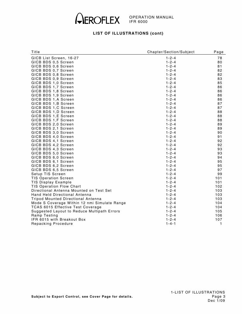
LIST OF ILLUSTRATIONS (cont)
Ti t le Chapter /Sect ion/Subject Page
GICB L is t Screen, 16-27 1-2-4 78 GICB BDS 0,5 Screen 1-2-4 80 GICB BDS 0,6 Screen 1-2-4 81 GICB BDS 0,7 Screen 1-2-4 82 GICB BDS 0,8 Screen 1-2-4 82 GICB BDS 0,9 Screen 1-2-4 83 GICB BDS 1,0 Screen 1-2-4 85 GICB BDS 1,7 Screen 1-2-4 86 GICB BDS 1,8 Screen 1-2-4 86 GICB BDS 1,9 Screen 1-2-4 86 GICB BDS 1,A Screen 1-2-4 86 GICB BDS 1,B Screen 1-2-4 87 GICB BDS 1,C Screen 1-2-4 87 GICB BDS 1,D Screen 1-2-4 88 GICB BDS 1,E Screen 1-2-4 88 GICB BDS 1,F Screen 1-2-4 88 GICB BDS 2,0 Screen 1-2-4 89 GICB BDS 2,1 Screen 1-2-4 89 GICB BDS 3,0 Screen 1-2-4 90 GICB BDS 4,0 Screen 1-2-4 91 GICB BDS 4,1 Screen 1-2-4 92 GICB BDS 4,2 Screen 1-2-4 92 GICB BDS 4,3 Screen 1-2-4 93 GICB BDS 5,0 Screen 1-2-4 93 GICB BDS 6,0 Screen 1-2-4 94 GICB BDS 6,1 Screen 1-2-4 95 GICB BDS 6,2 Screen 1-2-4 95 GICB BDS 6,5 Screen 1-2-4 97 Setup TIS Screen 1-2-4 99 TIS Operat ion Screen 1-2-4 101 TIS Disp lay Example 1-2-4 101 TIS Operat ion F low Char t 1-2-4 102 Di rect ional Antenna Mounted on Test Set 1-2-4 103 Hand Held Di rect ional Antenna 1-2-4 103 Tr ipod Mounted Di rect ional Antenna 1-2-4 103 Mode S Coverage Wi th in 12 nmi Simulate Range 1-2-4 104 TCAS 6015 Ef fect ive Test Coverage 1-2-4 104 Suggested Layout to Reduce Mul t ipath Errors 1-2-4 105 Ramp Test ing 1-2-4 106 IFR 6015 wi th Breakout Box 1-2-4 107 Repacking Procedure 1-4-1 1

OPERATION MANUAL IFR 6000
1-LIST OF ILLUSTRATIONS Subject to Export Control , see Cover Page for deta i ls . Page 4
Dec 1/09
THIS PAGE INTENTIONALLY LEFT BLANK.

OPERATION MANUAL IFR 6000
1-LIST OF TABLES Subject to Export Control , see Cover Page for deta i ls . Page 1
Dec 1/09
LIST OF TABLES
Ti t le Chapter /Sect ion/Subject Page
Test Ident i f ier Symbols 1-2-4 9 Common Usage GICB BDS 1-2-4 25 Protect ion Volume Parameters Versus Al t i tude 1-2-4 35 SL: F ie ld Val id Data 1-2-4 40 CA: F ie ld Val id Data 1-2-4 41 RI : F ie ld (Acquis i t ion) Val id Data 1-2-4 41 RI : F ie ld (Track ing) Val id Data 1-2-4 41 RAC: F ie ld Val id Data 1-2-4 41 ARA: F ie ld Val id Data 1-2-4 42 CVC: F ie ld Disp lay Data 1-2-4 48 VRC: F ie ld Disp lay Data 1-2-4 48 CHC: Fie ld Disp lay Data 1-2-4 48 HRC: Fie ld Disp lay Data 1-2-4 48 ESB: F ie ld Disp lay Data 1-2-4 49 ARA=Fie ld Val id Data 1-2-4 50 RAC=Fie ld Val id Data 1-2-4 51 GICB Suppor ted BDS Regis ters 1-2-4 77

OPERATION MANUAL IFR 6000
1-LIST OF TABLES Subject to Export Control , see Cover Page for deta i ls . Page 2
Dec 1/09
THIS PAGE INTENTIONALLY LEFT BLANK.

OPERATION MANUAL IFR 6000
1-SERVICE UPON RECEIPT OF MATERIALS Subject to Export Control , see Cover Page for deta i ls . Page 1
Dec 1/09
SERVICE UPON RECEIPT OF MATERIAL
Unpacking
Specia l -des ign pack ing mater ia l ins ide th is sh ipp ing car ton prov ides maximum protect ion for the IFR 6000. Avoid damaging the car ton and pack ing mater ia l dur ing equipment unpack ing. Use the fo l lowing s teps for unpack ing the IFR 6000.
● Cut and remove the seal ing tape on the car ton top and open the car ton.
● Grasp the IFR 6000 t rans i t case f i rmly , whi le rest ra in ing the sh ipp ing car ton, and l i f t the equipment and pack ing mater ia l ver t ica l ly .
● P lace the IFR 6000 t rans i t case and end cap pack ing on a su i tab le f la t , c lean and dry sur face.
● Remove the protect ive p last ic bag f rom the IFR 6000 t rans i t case.
● P lace protect ive p last ic bag and end cap pack ing mater ia l ins ide sh ipp ing car ton.
● Store the sh ipp ing car ton for fu ture use should the IFR 6000 need to be returned.
Checking Unpacked Equipment
● Inspect the equipment for damage incurred dur ing sh ipment . I f the equipment has been damaged, repor t the damage to Aerof lex.
● Check the equipment against the pack ing s l ip to see i f the sh ipment is complete. Repor t a l l d iscrepancies to Aerof lex.
IFR 6000 wi th Standard Accessor ies
DESCRIPTION PART NUMBER QTY
IFR 6000 72425 1
POWER SUPPLY 67366 1
ANTENNA 64579 1
BREAKOUT BOX 64580 1
ANTENNA SHIELD 64749 1
12 IN. COAXIAL CABLE 62401 1
72 IN. COAXIAL CABLE 62402 1
5 A FUSE 56080 1
TRANSIT CASE 10241 1
POWER CORD (US ONLY)
62302 1
POWER CORD (EUROPEAN)
64020 1
OPERATION MANUAL (CD-ROM)
6670 1
GETTING STARTED MANUAL (PAPER)
6096 1

OPERATION MANUAL IFR 6000
1-SERVICE UPON RECEIPT OF MATERIALS Subject to Export Control , see Cover Page for deta i ls . Page 2
Dec 1/09
THIS PAGE INTENTIONALLY LEFT BLANK.
OPERATION MANUAL IFR 6000
1-1-1 Subject to Export Control , see Cover Page for deta i ls . Page 1 Dec 1/09
SECTION 1 - DESCRIPTION
1. GENERAL DESCRIPTION AND CAPABILITIES
1.1 DESCRIPTION
INTERR
POWER CHARGE
BKLT
CTRS
REPLY DISPLAY
RF LVL
RANGE
FREQ
DME
RATE
SETUPDME
XPDR TCAS
05801
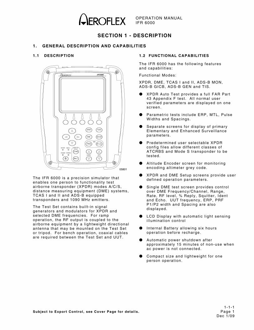
The IFR 6000 is a prec is ion s imulator that enables one person to funct ional i ty test a i rborne t ransponder (XPDR) modes A/C/S, d is tance measur ing equipment (DME) systems, TCAS I and I I and ADS-B equipped t ransponders and 1090 MHz emi t ters .
The Test Set conta ins bu i l t - in s ignal generators and modulators for XPDR and se lected DME f requencies. For ramp operat ion, the RF output is coupled to the a i rborne equipment by a l ightweight d i rect ional antenna that may be mounted on the Test Set or t r ipod. For bench operat ion, coax ia l cables are requi red between the Test Set and UUT.
1.2 FUNCTIONAL CAPABILITIES
The IFR 6000 has the fo l lowing features and capabi l i t ies :
Funct ional Modes:
XPDR, DME, TCAS I and I I , ADS-B MON, ADS-B GICB, ADS-B GEN and TIS.
● XPDR Auto Test prov ides a fu l l FAR Par t 43 Appendix F test . A l l normal user ver i f ied parameters are d isp layed on one screen.
● Parametr ic tests inc lude ERP, MTL, Pulse Widths and Spacings.
● Separate screens for d isp lay of pr imary Elementary and Enhanced Surve i l lance parameters.
● Predetermined user se lectable XPDR conf ig f i les a l low d i f ferent c lasses of ATCRBS and Mode S t ransponder to be tested.
● A l t i tude Encoder screen for moni tor ing encoding a l t imeter grey code.
● XPDR and DME Setup screens prov ide user def ined operat ion parameters.
● S ing le DME test screen prov ides contro l over DME Frequency/Channel , Range, Rate, RF level , % Reply , Squi t ter , Ident and Echo. UUT f requency, ERP, PRF P1/P2 width and Spacing are a lso d isp layed.
● LCD Disp lay wi th automat ic l ight sens ing i l luminat ion cont ro l
● In ternal Bat tery a l lowing s ix hours operat ion before recharge.
● Automat ic power shutdown af ter approx imate ly 15 minutes of non-use when ac power is not connected.
● Compact s ize and l ightweight for one person operat ion.
OPERATION MANUAL IFR 6000
1-1-1 Subject to Export Control , see Cover Page for deta i ls . Page 2 Dec 1/09
1.3 REGULATORY RESPONSIBILITIES
Effect ive Apr i l 6 , 1987, the Federa l Av iat ion Admin is t ra t ion (FAA) has requi red cer ta in tests be per formed on t ransponders, both convent ional ATCRBS and Mode S. In preparat ion for the insta l la t ion of new a i r t ra f f ic cont ro l radar fac i l i t ies , the FAA requi red new measurements to be per formed on ex is t ing t ransponders and inst i tu ted requi red tests for Mode S t ransponders. FAR (Federa l Av iat ion Regulat ions) Par t 43, Maintenance, Prevent ive Maintenance, Rebui ld ing and Al terat ion sect ion has been modi f ied to re f lect current technologies and improvements. Aerof lex has met a l l FAA requi rements and recommends that the user o f th is type of equipment rev iew the appropr ia te FAR, or contact the manufacturer o f the i r par t icu lar model o f t ransponder to ensure that proper procedures are fo l lowed.
Eurocontro l and the JAA have a lso incorporated new regulat ions for Mode S Elementary and Enhanced Surve i l lance. These requi rements inc lude Select ive Ident i f iers for h igh-densi ty t ra f f ic areas and became mandatory in May, 2003 for E lementary Surve i l lance and March, 2005 for Enhanced Surve i l lance.
The IFR 6000 has the capabi l i ty to thoroughly test these new funct ions to comply wi th upcoming requi rements. For fur ther in format ion regard ing these requi rements, v is i t www.eurocontro l . in t / .
OPERATION MANUAL IFR 6000
1-1-2 Subject to Export Control , see Cover Page for deta i ls . Page 1 Dec 1/09
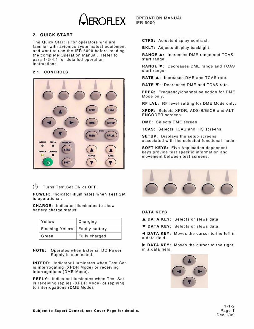
2. QUICK START
The Quick Star t is for operators who are fami l iar wi th av ion ics systems/ test equipment and want to use the IFR 6000 before reading the complete Operat ion Manual . Refer to para 1-2-4.1 for deta i led operat ion inst ruct ions.
2.1 CONTROLS
Turns Test Set ON or OFF.
POWER : Ind icator i l luminates when Test Set is operat ional .
CHARGE: Ind icator i l luminates to show bat tery charge s tatus;
Yel low Charg ing
F lashing Yel low Faul ty bat tery
Green Ful ly charged
NOTE: Operates when External DC Power Supply is connected.
INTERR: Ind icator i l luminates when Test Set is in ter rogat ing (XPDR Mode) or receiv ing in ter rogat ions (DME Mode) .
REPLY: Ind icator i l luminates when Test Set is receiv ing rep l ies (XPDR Mode) or rep ly ing to in ter rogat ions (DME Mode) .
CTRS: Ad justs d isp lay cont rast .
BKLT: Ad justs d isp lay back l ight .
RANGE : Increases DME range and TCAS star t range.
RANGE : Decreases DME range and TCAS star t range.
RATE : Increases DME and TCAS rate.
RATE : Decreases DME and TCAS rate.
FREQ: Frequency/channel se lect ion for DME Mode only .
RF LVL: RF level set t ing for DME Mode only .
XPDR: Selects XPDR, ADS-B/GICB and ALT ENCODER screens.
DME: Selects DME screen.
TCAS: Selects TCAS and TIS screens.
SETUP: Disp lays the setup screens assoc iated wi th the se lected funct ional mode.
SOFT KEYS: Five Appl icat ion dependent keys prov ide test spec i f ic in format ion and movement between test screens.
DATA KEYS
DATA KEY: Se lects or s lews data.
DATA KEY: Se lects or s lews data.
DATA KEY: Moves the cursor to the le f t in a data f ie ld .
DATA KEY: Moves the cursor to the r ight in a data f ie ld .

OPERATION MANUAL IFR 6000
1-1-2 Subject to Export Control , see Cover Page for deta i ls . Page 2 Dec 1/09
2.2 GENERAL SETUP
STEP PROCEDURE
1. Power Up: Press the POWER Key to power the Test Set On.
2 . Press SETUP Contro l Key to d isp lay setup screens. Cont inue press ing SETUP Contro l Key to cyc le to SETUP-GENERAL Screen. Use NEXT PARAM and PREV PARAM Sof t Keys to se lect each parameter .
B A T 2 .5 H r
P REV P A RA M
NEX T PA RA M
S ET U P - G EN ER AL
H/W TOOLS
P WR D OW N : 1 0 M IN S ERP UNITS:dBm UNITS:FEET REMOTE OPERATION:RS232
INFO
T
3 . Select PWR: Set to preferred power down t imeout .
4 . Select ERP UNITS: Set to preferred ERP uni ts .
5 . Select UNITS: Set to preferred uni ts .
2 .3 XPDR SETUP ANTENNA
STEP PROCEDURE
1. Refer to 1-1-2, F igure 1. Mount Di rect ional Antenna on Test Set and pos i t ion f r ic t ion h inge so Di rect ional Antenna is as shown. Connect shor t RF coaxia l cable between Antenna Connector and Test Set ANT Connector .
Antenna Mount ing F igure 1
2 . Refer to 1-1-2, F igure 2. Posi t ion Test Set ≤50 f t (15.24 m) f rom and in l ine of s ight wi th top/bot tom antenna.
3 . Power On Ai rcraf t and conf igure a i rcraf t for weight o f f wheels .
4 . Press POWER Key to power up the Test Set .

OPERATION MANUAL IFR 6000
1-1-2 Subject to Export Control , see Cover Page for deta i ls . Page 3 Dec 1/09
C. LINE OF SIGHT DISTANCEANTENNA SHIELD
TESTING BOTTOM ANTENNA
TESTING TOP ANTENNA
AIRCRAFT BLOCKING LINE OFUSE SETUP POSITION THAT HASNOT POSSIBLE OR PRACTICAL,OR SHIELDING TOP ANTENNA ISWHEN DESELECTING, TERMINATING
B. SETUP RANGE
A. SETUP HEIGHT
B.
A. C.SIGHT TO TOP ANTENNA.
05818A
Ramp Test ing F igure 2
5 . Press SETUP Contro l Key to d isp lay setup screens. Cont inue press ing SETUP Contro l Key to cyc le to SETUP-XPDR Screen. Use NEXT PARAM and PREV PARAM Sof t Keys to se lect each parameter .
B A T 2 .5 H r
A N T R A N G E A N T H E IG HT T OP: 1 2 f t 6 f t B OTT O M: 1 2 f t 4 f t D IR C AB L E L OS S: 1 . 3 d B A N T GA I N ( d B i) A NT C A B L E L O SS : 1 .3 d B 1 . 03 G H z: 7 . 1 1 . 09 G H z: 6 . 1 U UT A D D R E SS : A U T O M A N U A L A A : 12 3 45 6 PW R L I M : F A R 4 3 D IV ER S IT Y T E ST : ON C H EC K C A P: YE S
P REV P A RA M
NEX T PA RA M
S ET U P - X PD R
DIA G
A N T E N N A : B OT T OM R F PO R T : A N T E N N A
TE STDA T A

OPERATION MANUAL IFR 6000
1-1-2 Subject to Export Control , see Cover Page for deta i ls . Page 4 Dec 1/09
STEP PROCEDURE
6. Select ANTENNA: Set to TOP or BOTTOM depending on which a i rcraf t antenna Test Set is po int ing towards.
7. Select RF PORT: Set to ANTENNA.
8. Select ANT RANGE: Set to setup range f rom IFR 6000 antenna to UUT Antenna.
9. Select ANT HEIGHT: Set to setup height f rom IFR 6000 antenna to UUT Antenna.
10. Select ANT CABLE LOSS: Set to cable loss found on cable.
11. Select ANT GAIN (dBi ) : set 1 .03 GHz and 1.09 GHz antenna gain to f igures marked on suppl ied Di rect ional Antenna
12. Select UUT ADDRESS: Set to AUTO.
NOTE: I f a i rcraf t is on the ground set to MANUAL and enter in MANUAL ADDRESS. Mode S a l l -ca l ls do not work when the a i rcraf t is on the ground.
T13. Select DIVERSITY T: Set to OFF.
NOTE: To run d ivers i ty test set DIVERSITY to ON and insta l l boot to bot tom/top antenna.
T14. Select CHECK CAP: S Tet to YES.
T15. Select PWR LIM: Set to FAR 43. T
2.4 XPDR SETUP DIRECT CONNECT
STEP PROCEDURE
1. Connect long RF coaxia l cable between the a i rcraf t antenna feeder cable and Test Set RF I /O Connector .
2 . Power On Ai rcraf t and conf igure a i rcraf t for weight o f f wheels .
3 . Power Up: Press the POWER Key to power the Test Set .
Press SETUP Contro l Key to d isp lay setup screens. Cont inue press ing SETUP Contro l Key to cyc le to SETUP-XPDR Screen. Use NEXT PARAM and PREV PARAM Sof t Keys to se lect each parameter .
5 . Select ANTENNA: Set to TOP or BOTTOM depending on which a i rcraf t antenna Test Set is connected wi th .
6 . Select RF PORT: Set to DIRECT CONNECT.
7. Select DIR CABLE LOSS: Set cable loss to cable loss found on cable.
8. Select UUT ADDRESS: Set to AUTO.
NOTE: I f a i rcraf t is on the ground set to MANUAL and enter in MANUAL ADDRESS. Mode S a l l -ca l ls do not work when the a i rcraf t is on the ground.
9. Select DIVERSITY: Set to ON.
T10. Select CHECK CAP: S Tet to YES.
T11. Select PWR LIM: Set to FAR 43. T
OPERATION MANUAL IFR 6000
1-1-2 Subject to Export Control , see Cover Page for deta i ls . Page 5 Dec 1/09
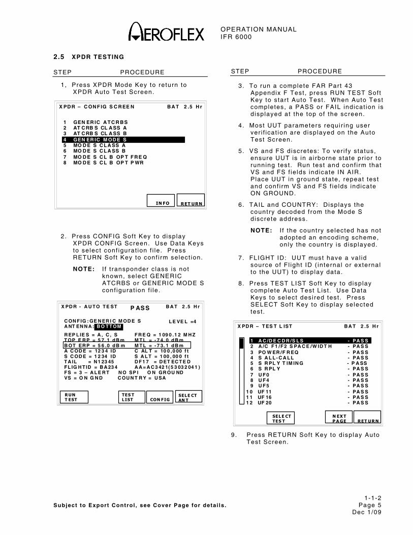
2.5 XPDR TESTING
STEP PROCEDURE
1, Press XPDR Mode Key to re turn to XPDR Auto Test Screen.
B A T 2 .5 H r
X PD R – C ON F IG S C R EE N
IN FO
1 GEN ER IC A T C R B S 2 AT C RB S CL A SS A 3 AT C RB S CL A SS B 4 GEN ER IC M OD E S 5 MO D E S C L A SS A 6 MO D E S C L A SS B 7 MO D E S C L B OP T F R E Q 8 MO D E S C L B OP T P WR
RET URN
2 . Press CONFIG Sof t Key to d isp lay XPDR CONFIG Screen. Use Data Keys to se lect conf igurat ion f i le . Press RETURN Sof t Key to conf i rm se lect ion.
TNOTE: I f t ransponder c lass is not known, se lect GENERIC ATCRBS or GENERIC MODE S conf igurat ion f i le .
R EP L IE S = A , C , S F R E Q = 1 09 0 .1 2 M H Z TOP E R P = 5 7. 1 dB m M TL = - 7 4. 0 dB m
B OT ER P = 5 6 .0 dB m M TL = - 7 3. 1 dB mT R P A C OD E = 12 3 4 ID C AL T = 10 0 ,0 00 f t
S C OD E = 1 2 34 ID S A L T = 1 00 , 00 0 f t TA IL = N 1 23 45 D F 1 7 = D ET EC T E D
FL IG H TID = B A 23 4 A A = A C 3 42 1( 5 3 03 2 04 1 ) FS = 3 – A L E R T N O SP I O N GR OU ND
VS = O N G N D C OU N T R Y = U SA
C ON FIG : GE N ER I C M OD E S A NT EN N A : B O TT OM
B A T 2 .5 H r
RUN T EST TES T
LIST
X PD R - A U TO TE ST
CON FIG
SELE CTAN T
P AS S
L E VE L =4
STEP PROCEDURE
3. To run a complete FAR Par t 43 Appendix F Test , press RUN TEST Sof t Key to s tar t Auto Test . When Auto Test completes, a PASS or FAIL ind icat ion is d isp layed at the top of the screen.
4 . Most UUT parameters requi r ing user ver i f icat ion are d isp layed on the Auto Test Screen.
T5. VS T and FS d iscretes: To ver i fy s ta tus, ensure UUT is in a i rborne s tate pr ior to running test . Run test and conf i rm that VS and FS f ie lds ind icate IN AIR. P lace UUT in ground state, repeat test and conf i rm VS and FS f ie lds ind icate ON GROUND.
6 . TAIL and COUNTRY: Disp lays the country decoded f rom the Mode S d iscrete address.
NOTE: I f the country se lected has not adopted an encoding scheme, on ly the country is d isp layed.
7 . FLIGHT ID: UUT must have a va l id source of F l ight ID ( in ternal or external to the UUT) to d isp lay data.
8 . Press TEST LIST Sof t Key to d isp lay complete Auto Test L is t . Use Data Keys to se lect des i red test . Press SELECT Sof t Key to d isp lay se lected test .
B A T 2 .5 H r
X PD R – T ES T L IST
1 A C /D E C D R /S L S - PA S S 2 A /C F 1 /F 2 S PA C E /W ID T H - PA S S 3 PO W ER /F R EQ - PA S S 4 S A L L - C A L L - PA S S 5 S R PL Y T IM IN G - P A SS 6 S R PL Y - PA S S 7 U F 0 - PA S S 8 U F 4 - PA S S 9 U F 5 - PA S S 1 0 UF 11 - PA S S 1 1 UF 16 - PA S S 1 2 UF 20 - PA S S
RET UR N
SEL E CT TES T
N EX T P A GE
9 . Press RETURN Sof t Key to d isp lay Auto Test Screen.

OPERATION MANUAL IFR 6000
1-1-2 Subject to Export Control , see Cover Page for deta i ls . Page 6 Dec 1/09
2.5.1 ADS-B/GICB TESTING
STEP PROCEDURE
1. Per form XPDR SETUP ANTENNA procedure or XPDR SETUP DIRECT CONNECT procedure.
2. Press SETUP Key unt i l SETUP XPDR screen is d isp layed.
3 . Press ADS-B SETUP Sof t Key to d isp lay ADS-B/GICB Setup Screen. Use NEXT PARAM and PREV PARAM Sof t Keys to se lect each parameter .
PO S D EC O D E: GL O B A L L A T : 3 8 2 5 35 N L ON G : 1 26 3 5 3 5 W AD SB G EN :D F 17 AD SB M O N :D F 17 GIC B :D F 20
B A T 2 .5 H r
T ES T D A TA
PR EV P ARA M
NEX T PA RA M
S ET U P - A D SB
RET URN
4 . Select POS DECODE: Set to GLOBAL to use g lobal CPR algor i thm for la t i tude and longi tude decoding or s imulat ion. Set to LOCAL to use local CPR algor i thm for la t i tude and longi tude decoding or s imulat ion. POS DECODE is for BDS 0,5 and BDS 0,6.
5 . Select LAT: Enter loca l la t i tude in degrees, minutes and seconds.
6 . Select LONG: Enter loca l longi tude in degrees, minutes and seconds.
7. Select ADS-B GEN: Set DF17 or DF18 extended squi t ters to be generated.
8 . Select ADS-B MON: Set DF17 or DF18 extended squi t ters to be moni tored.
9 . Select GICB: Set DF20 or DF21 to be requested wi th GICB protocol .
2.5.1.1 ADS-B MON
STEP PROCEDURE
1. Press XPDR Mode Key unt i l ADS-B/GICB MAIN menu is d isp layed.
B A T 2 .5 H r
A DS BMO N GI CB
A D S- B / GI C B M A IN
A D SBG EN
2 . Press the ADS-B MON Sof t Key to d isp lay the ADS-B MON l is t screen.
B A T 2 .5 H r
1 0, 5 A I RB O R N E PO S - AV A IL 2 0, 6 S U RF A C E PO S - N O T C A P 3 0, 8 I D EN T & C A T - AV A IL 4 0, 9 A I RB O R N E VE L - AV A IL 5 6, 1 A / C S T A T U S - AV A IL 6 6, 2 T A R G ST A T E - AV A IL 7 6, 5 A / C OP S T A T U S - N O S QT R 8 0, A T EST M SG - AV A IL
RUNT ES T
B DS DA TA
A D S- B M ON DF 17
RET URN
3 . Press RUN TEST sof t key to s tar t tes t . When a speci f ic extended squi t ter BDS is captured, AVAIL wi l l be d isp layed to the r ight o f the BDS name.

OPERATION MANUAL IFR 6000
1-1-2 Subject to Export Control , see Cover Page for deta i ls . Page 7 Dec 1/09
STEP PROCEDURE
4. Use Data Keys to se lect spec i f ic BDS and press BDS DATA sof t key to d isp lay se lected BDS screen. Refer to ADS-B MON BDS screen example.
B A T 2 .5 H r
B D S= 0 ,5 A I R B OR N E PO S T YP E= 14 DF 17 A A= 3 A C 42 1 ( 1 6 54 2 04 1 ) C O U N T = 10 0 0 M E= 00 0 00 0 00 0 0 00 00 P ER I OD = D EF AU L T L A T = 3 7 3 9 00 N L O N G= 9 7 2 5 48 W PO S= GL O B A L SA F = 1 T = N /U T C SU R V EI L L A N C E ST A T US = N O IN F O B A RO P R ES A L T = 13 10 2 5 f t GN S S AL T = N/ A
RUN T ES T
PRE V TES T
A D S- B M ON BD S 0 , 5 A V A IL
NEX T TES T
RET URN
5 . Press Return sof t key to return to ADS-B MON l is t screen or press PREV TEST or NEXT TEST sof t keys to se lect speci f ic ADS-B MON BDS screens.
2.5.1.2 ADS-B GEN
STEP PROCEDURE
1. Press XPDR Mode Key unt i l ADS-B/GICB Main Menu is d isp layed.
2. Pres ADSB GEN to d isp lay the ADSB GEN Lis t Screen.
B A T 2 .5 H r
1 0, 5 A I RB O R N E PO S - D IS AB L E D 2 0, 6 S U RF A C E PO S - D IS AB L E D 3 0, 8 I D EN T & C A T - D IS AB L E D 4 0, 9 A I RB O R N E VE L - D IS AB L E D 5 6, 1 A / C S T A T U S - D IS AB L E D 6 6, 2 T A R G ST A T E - D IS AB L E D 7 6, 5 A / C OP S T A T U S - D IS AB L E D
8 0, A T ES T M S G - D IS AB L E D
RUNT ES T
B DS DA TA
ST ORE DA TA
A D S- B M ON DF 17
B DSON
RET URN
3 . Press BDS ON Sof t Key to enable se lected test l is t i tems.
4 . Press RUN TEST Sof t Key to s tar t tes t .
5 . Press BDS DATA to enter se lected test .
OPERATION MANUAL IFR 6000
1-1-2 Subject to Export Control , see Cover Page for deta i ls . Page 8 Dec 1/09
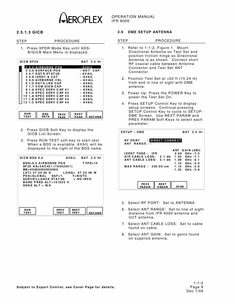
2.5.1.3 GICB
STEP PROCEDURE
1. Press XPDR Mode Key unt i l ADS-B/GICB Main Menu is d isp layed.
1 0 ,5 A I R B OR N E P OS - A VA I L 2 0 ,6 S U R F A C E PO S - N O T C A P 3 0 ,7 S QT R ST AT US - A V A IL 4 0 ,8 I D EN T & C A T - A VA IL 5 0 ,9 A I R B OR N E V EL - A V AI L 6 1 ,0 D A T A L N K C A P - A VA IL 7 1 ,7 C O M G IC B C A P - A VA IL 8 1 ,8 S PE C S ER V C AP # 1 - A VA IL 9 1 ,9 S PE C S ER V C AP # 2 - A VA IL 1 0 1, A S PE C S ER V C AP # 3 - A VA IL 1 1 1, B S PE C S ER V C AP # 4 - A VA IL 1 2 1, C S PE C S ER V C AP # 5 - A VA IL
B A T 2 .5 H r
RUN T ES T
B DS DA TA
GI C B D F 2 0
RET URN
N EX T P A GE
PR EV PA GE
2 . Press GICB Sof t Key to d isp lay the GICB L is t Screen.
3 . Press RUN TEST sof t key to s tar t tes t . When a BDS is avai lab le, AVAIL wi l l be d isp layed to the r ight o f the BDS name.
B A T 2 .5 H r
B D S= 0 ,5 A I R B OR N E PO S T YP E= 14 DF 20 A A= 3 A C 42 1 ( 1 6 54 2 04 1 ) MB = 0 0 00 0 00 0 00 0 00 0 L A T = 3 7 3 9 00 N L O N G= 9 7 2 5 48 W PO S= GL O B A L SA F = 1 T = N /U T C SU R V EI L L A N C E ST A T US = N O IN F O B A RO P R ES A L T = 13 10 2 5 f t GN S S AL T = N/ A
RUN T ES T
PRE V TES T
GI C B B D S 0 ,5 A VA I L
NEX T TES T
RET URN
2 .6 DME SETUP ANTENNA
STEP PROCEDURE
1. Refer to 1-1-2, F igure 1. Mount Di rect ional Antenna on Test Set and pos i t ion f r ic t ion h inge so Di rect ional Antenna is as shown. Connect shor t RF coaxia l cable between Antenna Connector and Test Set ANT Connector .
2 . Posi t ion Test Set a t ≤50 f t (15.24 m) f rom and in l ine of s ight wi th DME antenna.
3. Power Up: Press the POWER Key to power the Test Set On.
4 . Press SETUP Contro l Key to d isp lay setup screens. Cont inue press ing SETUP Contro l Key to cyc le to SETUP-DME Screen. Use NEXT PARAM and PREV PARAM Sof t Keys to se lect each parameter .
B A T 2 .5 H r
NEX T
P ARA M
S ET U P – D M E
DI AG
R F PO R T : DI R EC T C ON N E C T A N T R A N G E : - A NT G A I N ( d B I) I D EN T T ON E : IF R 0 .9 6 GH z : 7 .5 D I R C A B L E L O SS : 2 . 1 d b 1 . 03 GH z : 7 .1 A N T C A B L E L OS S: 2 . 1 d b 1 . 09 GH z : 6 .1 1 . 15 GH z : 5 .0 M A X R A N G E : 2 00 .0 0 n m 1 . 15 GH z : 5 .0 1 . 22 GH z : 2 .8
PR EVPA RA M
5 . Select RF PORT: Set to ANTENNA.
6. Select ANT RANGE: Set to l ine of s ight d is tance f rom IFR 6000 antenna and UUT antenna.
7. Select ANT CABLE LOSS: Set to cable found on cable.
8 . Select ANT GAIN: Set to ga ins found on suppl ied antenna.
OPERATION MANUAL IFR 6000
1-1-2 Subject to Export Control , see Cover Page for deta i ls . Page 9 Dec 1/09
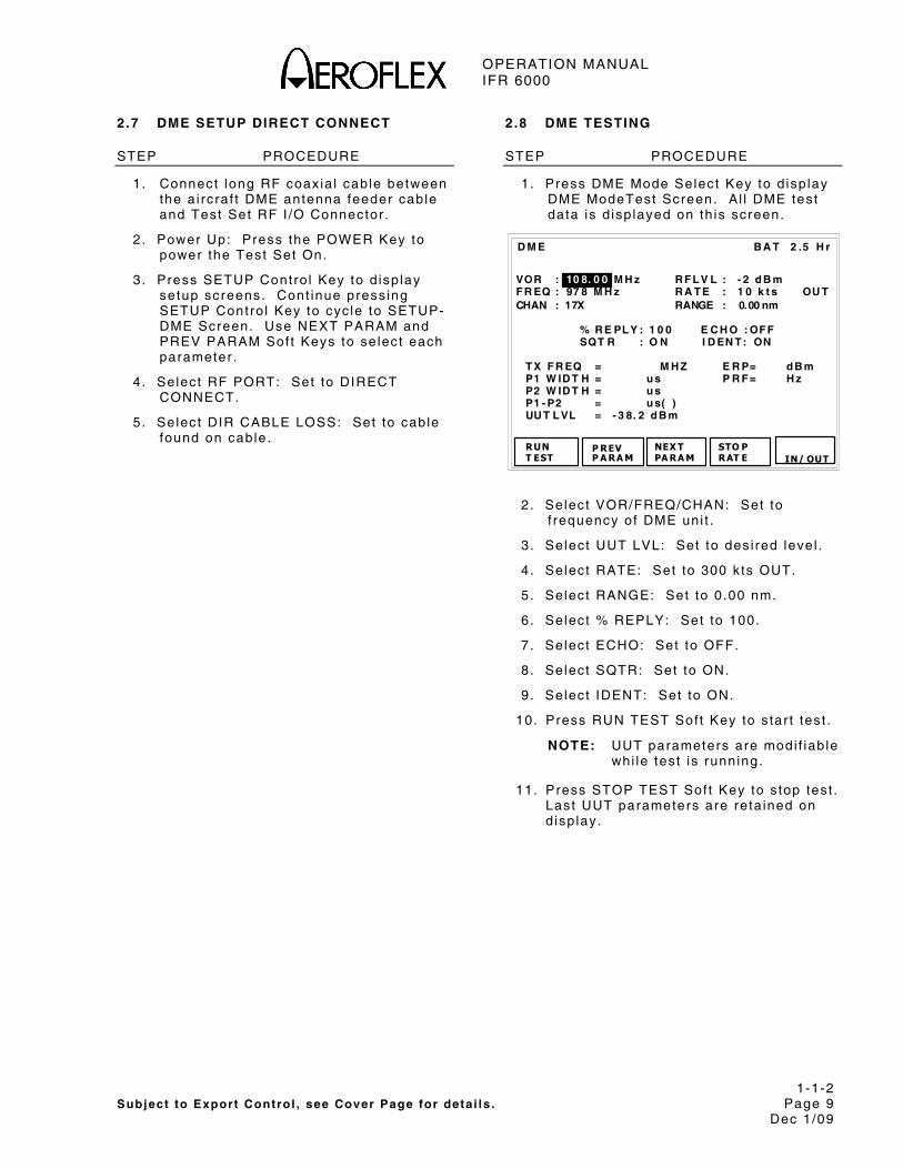
2.7 DME SETUP DIRECT CONNECT
STEP PROCEDURE
1. Connect long RF coaxia l cable between the a i rcraf t DME antenna feeder cable and Test Set RF I /O Connector .
2 . Power Up: Press the POWER Key to power the Test Set On.
3 . Press SETUP Contro l Key to d isp lay setup screens. Cont inue press ing SETUP Contro l Key to cyc le to SETUP-DME Screen. Use NEXT PARAM and PREV PARAM Sof t Keys to se lect each parameter .
4 . Select RF PORT: Set to DIRECT CONNECT.
5. Select DIR CABLE LOSS: Set to cable found on cable.
2.8 DME TESTING
STEP PROCEDURE
1. Press DME Mode Select Key to d isp lay DME ModeTest Screen. A l l DME test data is d isp layed on th is screen.
B A T 2 .5 H r
% R E PL Y : 1 0 0 E C H O : OF F SQT R : O N I D EN T : ON
T X F R EQ = M H Z E R P= d B m P1 W ID T H = u s P R F = H z P2 W ID T H = u s P1 - P2 = u s( ) UU T L VL = - 3 8. 2 d B m
RUNT EST
P REV P A RA M
NEX T PA RA M
D M E
STO PRAT E
VOR : 10 8. 0 0 M H z R F L V L : - 2 d B m F R EQ : 97 8 M H z R A T E : 1 0 k t s OU T CHAN : 17X RANGE : 0.00 nm
IN/ OUT
2 . Select VOR/FREQ/CHAN: Set to f requency of DME uni t .
3 . Select UUT LVL: Set to des i red level .
4 . Select RATE: Set to 300 k ts OUT.
5. Select RANGE: Set to 0.00 nm.
6. Select % REPLY: Set to 100.
7. Select ECHO: Set to OFF.
8. Select SQTR: Set to ON.
9. Select IDENT: Set to ON.
10. Press RUN TEST Sof t Key to s tar t tes t .
NOTE: UUT parameters are modi f iab le whi le test is running.
11. Press STOP TEST Sof t Key to s top test . Last UUT parameters are re ta ined on d isp lay.

OPERATION MANUAL IFR 6000
1-1-2 Subject to Export Control , see Cover Page for deta i ls . Page 10 Dec 1/09
2.9 TCAS SETUP ANTENNA
STEP PROCEDURE
1. Refer to 1-1-2, F igure 1. Mount Di rect ional Antenna on Test Set and pos i t ion f r ic t ion h inge so Di rect ional Antenna is as shown. Connect shor t RF coaxia l cable between Antenna Connector and Test Set ANT Connector .
2 . Posi t ion Test Set a t Forward Sector Test Locat ion, ≤50 f t (15.24 m) f rom and in l ine of s ight wi th TCAS top antenna.
3. Power Up: Press the POWER Key to power the Test Set On.
4 . Press SETUP Contro l Key to d isp lay setup screens. Cont inue press ing SETUP Contro l Key to cyc le to SETUP-TCAS Screen. Use NEXT PARAM and PREV PARAM Sof t Keys to se lect each parameter .
R F PO RT : AN T EN N A A N T R A NG E : 1 2 f t A N T H EI GH T : 1 f t U U T A D DR ES S: A U T O M A N U A L A A : 00 0 00 0 D IR C A B L E L OSS : 1 .3 d B A N T C A BL E: U S ER D EF I N ED A N T C A BL E L OS S: 0 . 1 d B AN T GA I N ( d B i) S QU IT T ER S : ON 1 . 03 GH z : 7 .1 A L T R EP OR T I N G: O N 1 .0 9 G H z: 6 .1 D I SPL A YE D A L T : R E L A T IV E T E ST SE T AA : A 9 2 49 3
B A T 2 .5 H r
RE PLY PA RA M
NEX T P ARA M
S ET U P -T C A S
DI AG
PR EV PA RA M
ST OR E/RE CA LL
5 . Select RF PORT: Set to ANTENNA.
6. Select ANT RANGE: Set to setup range f rom antenna.
7. Select ANT HEIGHT: Set to setup height f rom antenna.
8. Select UUT ADDRESS: Set to AUTO.
NOTE: I f a i rcraf t is on the ground, set to MANUAL and enter in MANUAL ADDRESS. Mode S a l l -ca l ls do not work when the a i rcraf t is on the ground.
STEP PROCEDURE
9. Select ANT CABLE LOSS: Set to cable loss found on cable.
10. Select ANT GAIN (dBi) : Set 1.03 GHz and 1.09 GHz antenna gain to f igures marked on suppl ied Di rect ional Antenna.
11. Select SQUITTERS: Set to ON.
11. Select ALT REPORTING: Set to ON.
12. Select DISPLAYED ALT: Set to RELATIVE.
13. Select TEST SET AA: Set to A92493.
TNOTE: TEST SET AA needs to be d i f ferent than the surrounding a i rcraf t .

OPERATION MANUAL IFR 6000
1-1-2 Subject to Export Control , see Cover Page for deta i ls . Page 11 Dec 1/09
2.10 TCAS TESTING
STEP PROCEDURE
1. Press TCAS Mode Select Key to d isp lay TCAS Test Screen.
B A T 2 .5 H r
S C EN A R I O: 0 - C U ST OM T C A S T Y PE : T C A S I I %R EP L Y: 1 0 0 I N T R U D ER T YP E: M OD E S R A N GE S T A R T: 8 . 00 n m S T O P: - - R A N GE R AT E : 30 0 k t s A L T ST AR T : + 20 0 f t ST OP: - - A L T R A T E : C ON V ER G E : ON U U T A L T : 31 2 00 f t A L T D E T E CT : O N F R E Q= 1 0 30 . 00 0 M H z E R P= 5 7 .0 d B m R A N GE = 8. 0 0 n m IN A L T = +2 0 0 f t T C A S S T A T U S= T R A C K IN G S T A T U S= N ON - T H R E AT E N C OU N T ER = 0 : 0 0
RUN T ES T
PR EV P ARA M
NEX T P ARA M
T C A S
M ON
ST ORE/RE CA LL
2 . Select SENARIO: Set to CUSTOM.
3. Select TCAS TYPE: Set to TCAS I I .
NOTE: I f test ing a TCAS I system set to TCAS I .
4 . Select % REPLY: Set to 100.
5 . Select INTRUDER TYPE: Set to ATCRBS or Mode S.
6. Select RANGE START: Set to 8 nm.
7. Select RANGE RATE: Set to 300 kts .
8 . Select ALT START: Set to +200 f t .
9 . Select CONVERGE: Set to ON.
10. Select ALT DETECT: Set to ON.
11. Press RUN TEST Sof t Key to s tar t tes t .
12. Ver i fy TCAS STATUS disp lays AQUIRING and then TRACKING. When TRACKING is annunciated, an in t ruder should be d isp layed on the TCAS d isp lay.
STEP PROCEDURE
13. Ver i fy UUT v isual and audio operat ion:
NOTE: Ver i fy Traf f ic Advisory at 40 sec unt i l encounter t ime.
● Ver i fy Resolut ion Advisory at 25 sec unt i l encounter t ime
● Ver i fy TCAS bear ing reads 0° (±15° ) .
NOTE: I f Radio Al t imeter A l t i tude is be low 500 f t , RA’s are inh ib i ted.
NOTE: TCAS I systems do not issue RA’s .
14. Press STOP TEST Sof t Key to s top test .

OPERATION MANUAL IFR 6000
1-1-2 Subject to Export Control , see Cover Page for deta i ls . Page 12 Dec 1/09
2.11 TIS SETUP ANTENNA
STEP PROCEDURE
1. Refer to 1-1-2, F igure 1. Mount Di rect ional Antenna on Test Set and pos i t ion f r ic t ion h inge so Di rect ional Antenna is as shown. Connect shor t RF coaxia l cable between Antenna Connector and Test Set ANT Connector .
2 . Posi t ion Test Set ≤50 f t (15.24 m) f rom and in l ine of s ight wi th top/bot tom antenna.
3 . Power On Ai rcraf t and conf igure a i rcraf t for weight o f f wheels .
4 . Power Up: Press the POWER Key to power the Test Set On.
R F PO RT : DI R EC T C ON N E C T AN T R A N GE : 1 2 f t H E IG H T : 1 2 f t D IR CA B L E L OS S: 1 . 3 d B A N T GA I N ( d B i) A NT C A B L E :U SE R D E F IN E D 1. 03 G Hz : 7 .1 A NT C A B L E L OS S: 1 .3 d B 1. 09 G Hz : 6 .1 U UT A D D R E SS :A U T O M A N U A L A A : 12 3 45 6
B A T 2 .5 H r
PR EV PA RA M
S ET U P -T IS
NEX T P ARA M
5 . Press SETUP Contro l Key to d isp lay setup screens. Press SETUP Contro l Key to d isp lay SETUP-TIS Screen. Use NEXT PARAM and PREV PARAM Sof t Keys to se lect each parameter .
6 . Select RF PORT: Set to ANTENNA.
7. Select ANT RANGE: Set to setup range f rom IFR 6000 antenna to UUT Antenna.
8. Select ANT HEIGHT: Set to setup height f rom IFR 6000 antenna to UUT Antenna.
9. Select ANT CABLE LOSS: Set to cable loss found on cable.
STEP PROCEDURE
10. Select ANT GAIN (dBi ) : set 1 .03 GHz and 1.09 GHz antenna gain to f igures marked on suppl ied Di rect ional Antenna.
11. Select UUT ADDRESS: Set to AUTO.
NOTE: I f a i rcraf t is on the ground, set to MANUAL and enter MANUAL ADDRESS. Mode S a l l -ca l ls do not work when the a i rcraf t is on the ground.

OPERATION MANUAL IFR 6000
1-1-2 Subject to Export Control , see Cover Page for deta i ls . Page 13 Dec 1/09
2.12 TIS SETUP DIRECT CONNECT
STEP PROCEDURE
1. Connect long RF coaxia l cable between a i rcraf t antenna feeder cable and Test Set RF I /O Connector .
2 . Power On Ai rcraf t and conf igure a i rcraf t for weight o f f wheels .
3 . Power Up: Press POWER Key to power the Test Set .
4 . Press SETUP Contro l Key to d isp lay setup screens. Press SETUP Contro l Key unt i l SETUP-TIS Screen is d isp layed. Use NEXT PARAM and PREV PARAM Sof t Keys to se lect each parameter .
5 . Select RF PORT: Set to DIRECT CONNECT.
6. Select DIR CABLE LOSS: Set cable loss to cable loss found on cable.
7. Select UUT ADDRESS: Set to AUTO.
2.13 TIS TESTING
STEP PROCEDURE
1. Press TCAS Mode Key unt i l T IS Test Screen is d isp layed.
B A T 2 .5 H r
T A R G ET S : 5 U U T H DG : 1 80 d e g 1 2 3 4 5 B R G( d e g ) : 1 20 9 0 23 4 1 82 2 3 R N G( n m) : 6 . 00 4 . 00 3 .0 0 2 .0 0 1. 00 A L T ( f t ) : 35 0 0 2 0 00 1 00 0 5 00 0 A L T R A T E: C L IM B L E VE L L EV EL C L IM B L EV EL H D G( d e g ) : 2 34 1 78 5 6 2 2 0 T R A F F I C : P R OX PR O X PR O X PR O X T R F C A D D R = 3 A C4 2 1 ( 16 5 42 0 4 1) N 1 23 4 5 T S C R = 5 T SD R = 1 A L T = 12 6 70 0 f t T I S ST A T US = C ON N E CT IN G I N F O= 0 00 0
RUNT ES T
P REV P A RA M
NEX T PA RA M
T I S
2 . Use NEXT PARAM and PREV PARAM Sof t Keys to se lect each of the fo l lowing parameters:
TARGETS: Sets the number of s imulated targets 0 to 5.
UUT HDG: Prov ides entry for UUT Heading in degrees. This or ientates the target bear ings wi th respect to UUT (a i rcraf t ) heading.
BRG: Sets target bear ing re la t ive to UUT (a i rcraf t ) in degrees
RNG: Sets targets range re la t ive to UUT (a i rcraf t ) in naut ica l mi les.
ALT: Sets target a l t i tude re la t ive to UUT (a i rcraf t ) in feet .
ALT RATE: Sets Al t i tude Rate annunciat ion on TIS d isp lay.
HDG: Sets target Heading in degrees.
TRAFFIC: Sets target t ra f f ic s tatus on TIS d isp lay.
3 . Press RUN Sof t Key to s tar t tes t .

OPERATION MANUAL IFR 6000
1-1-2 Subject to Export Control , see Cover Page for deta i ls . Page 14 Dec 1/09
STEP PROCEDURE
4. TIS d isp lay shows the se lected target parameters in accordance wi th the se lect ions:
TIS STATUS f ie ld ind icates TIS connect ion s ta tus.
ADDR ind icates UUT Ai rcraf t Address.
ALT UUT f ie ld d isp lays UUT a i rcraf t a l t i tude.
TSCR f ie ld ind icates number of TIS connects requested f rom UUT.
TSDR f ie ld ind icates number of TIS 0disconnects requested f rom UUT.

OPERATION MANUAL IFR 6000
1-2-1 Subject to Export Control , see Cover Page for deta i ls . Page 1
Dec 1/09
SECTION 2 - OPERATION
1. INSTALLATION
1.1 GENERAL
The IFR 6000 is powered by an in ternal L i th ium Ion bat tery pack. The Test Set is suppl ied wi th an external DC Power Supply that enables the operator to recharge the bat tery when connected to AC power.
NOTE: The IFR 6000 can operate cont inuously on AC power v ia the DC Power Supply , for serv ic ing and/or bench tests .
Refer to 1-2-2, F igure 2 for locat ion of cont ro ls , connectors or ind icators .
1.2 BATTERY OPERATION
The in ternal bat tery is equipped to power the IFR 6000 for s ix hours of cont inuous use, a f ter which t ime, the IFR 6000 bat tery needs recharg ing. Bat tery Operat ion T ime Remain ing ( in Hours) is d isp layed on a l l screens.
The IFR 6000 conta ins an automat ic t ime-out to conserve power. I f a key is not pressed wi th in a 5 to 20 minute t ime per iod, the Test Set shuts Of f (on ly when us ing bat tery power) . The Power Down Time may be set in the Setup Screen.
1.3 BATTERY CHARGING
The bat tery charger operates whenever DC power (11 to 32 Vdc) is appl ied to the Test Set wi th the suppl ied DC Power Supply or a su i tab le DC power source. When charg ing, the bat tery reaches a 100% charge in approx imate ly four hours. The in ternal bat tery charger a l lows the bat tery to charge between a temperature range of 5° to 40°C. The IFR 6000 can operate, connected to an external DC source, outs ide the bat tery charg ing temperature range (5° to 40°C).
The bat tery should be charged every three months (min imum) or d isconnected for long term inact ive s torage per iods of more than s ix months. The Bat tery must be removed when condi t ions surrounding the Test Set are <-20°C or >60°C.
1 .4 SAFETY PRECAUTIONS
The fo l lowing safety precaut ions must be observed dur ing insta l la t ion and operat ion. Aerof lex assumes no l iab i l i ty for fa i lure to comply wi th any safety precaut ion out l ined in th is manual .
1.4.1 Complying with Instruct ions
Insta l la t ion/operat ing personnel should not a t tempt to insta l l or operate the IFR 6000 wi thout reading and comply ing wi th inst ruct ions conta ined in th is manual . A l l procedures conta ined in th is manual must be per formed in exact sequence and manner descr ibed.
1.4.2 Grounding Power Cord
WARNING: DO NOT USE A THREE-PRONG TO TWO-PRONG ADAPTER PLUG. DOING SO CREATES A SHOCK HAZARD BETWEEN THE CHASSIS AND ELECTRICAL GROUND.
For AC operat ion, the AC L ine Cable, connected to the DC Power Supply , is equipped wi th s tandard three-prong p lug and must be connected to a proper ly grounded three-prong receptac le that is eas i ly access ib le . I t is the customer 's responsib i l i ty to :
● Have a qual i f ied e lect r ic ian check receptac le(s) for proper grounding.
● Replace any s tandard two-prong receptac le(s) wi th proper ly grounded three-prong receptac le(s) .
1.4.3 Operat ing Safety
Due to potent ia l for e lect r ica l shock wi th in the Test Set , the Case Assembly must be c losed when the Test Set is connected to an external power source.
Bat tery rep lacement , fuse rep lacement and in ternal ad justments must on ly be per formed by qual i f ied serv ice technic ians.
OPERATION MANUAL IFR 6000
1-2-1 Subject to Export Control , see Cover Page for deta i ls . Page 2
Dec 1/09
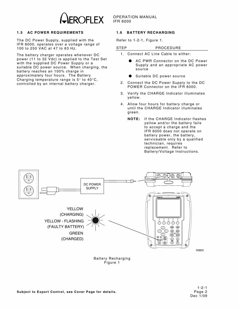
1.5 AC POWER REQUIREMENTS
The DC Power Supply , suppl ied wi th the IFR 6000, operates over a vo l tage range of 100 to 250 VAC at 47 to 63 Hz.
The bat tery charger operates whenever DC power (11 to 32 Vdc) is appl ied to the Test Set wi th the suppl ied DC Power Supply or a su i tab le DC power source. When charg ing, the bat tery reaches an 100% charge in approx imate ly four hours. The Bat tery Charg ing temperature range is 5° to 40°C, contro l led by an in ternal bat tery charger .
1 .6 BATTERY RECHARGING
Refer to 1-2-1, F igure 1.
STEP PROCEDURE
1. Connect AC L ine Cable to e i ther :
● AC PWR Connector on the DC Power Supply and an appropr ia te AC power source
● Sui tab le DC power source
2. Connect the DC Power Supply to the DC POWER Connector on the IFR 6000.
3 . Ver i fy the CHARGE Indicator i l luminates ye l low.
4 . A l low four hours for bat tery charge or unt i l the CHARGE Indicator i l luminates green.
NOTE: I f the CHARGE Indicator f lashes ye l low and/or the bat tery fa i ls to accept a charge and the IFR 6000 does not operate on bat tery power, the bat tery , serv iceable on ly by a qual i f ied technic ian, requi res rep lacement . Refer to Bat tery /Vol tage Inst ruct ions.
DC POWERSUPPLY
YELLOW(CHARGING)
YELLOW - FLASHING(FAULTY BATTERY)
(CHARGED)GREEN
05803
Bat tery Recharg ing F igure 1

OPERATION MANUAL IFR 6000
1-2-1 Subject to Export Control , see Cover Page for deta i ls . Page 3
Dec 1/09
1.7 EXTERNAL CLEANING
The fo l lowing procedure conta ins rout ine inst ruct ions for c leaning the outs ide of the Test Set .
CAUTION: DISCONNECT POWER FROM TEST SET TO AVOID POSSIBLE DAMAGE TO ELECTRONIC CIRCUITS.
STEP PROCEDURE
1. Clean f ront panel but tons and d isp lay face wi th sof t l in t - f ree c lo th. I f d i r t is d i f f icu l t to remove, dampen c lo th wi th water and a mi ld l iqu id detergent .
2 . Remove grease, fungus and ground- in d i r t f rom sur faces wi th sof t l in t - f ree c lo th dampened (not soaked) wi th isopropy l a lcohol .
3 . Remove dust and d i r t f rom connectors wi th sof t -br is t led brush.
4 . Cover connectors , not in use, wi th su i tab le dust cover to prevent tarn ish ing of connector contacts .
5 . Clean cables wi th sof t l in t - f ree c lo th.
6 . Paint exposed meta l sur face to avoid corros ion.

OPERATION MANUAL IFR 6000
1-2-1 Subject to Export Control , see Cover Page for deta i ls . Page 4
Dec 1/09
THIS PAGE INTENTIONALLY LEFT BLANK.

OPERATION MANUAL IFR 6000
1-2-2 Subject to Export Control , see Cover Page for deta i ls . Page 1
Dec 1/09
2. CONTROLS, CONNECTORS AND INDICATORS
21
REMOTE
VIDEOSYNC RF I/O ANT
REMOTE
XPDR TCAS
DME SETUP
FREQ RF LVL
CTRS
BKLT
DME
INTERR REPLY
POWER CHARGE
RANGE RATE
DISPLAY
1 2 3 4 5
7
11
19
20
22
23
28
29
27
26
24
18
16
17
15
14
13
12
10
9
8
05804
6
25
IFR 6000 Front Panel F igure 1

OPERATION MANUAL IFR 6000
1-2-2 Subject to Export Control , see Cover Page for deta i ls . Page 2
Dec 1/09
NUMERICAL LOCATION LIST ALPHABETICAL LOCATION LIST
1. SYNC Connector
2 . VIDEO Connector
3 . DC POWER Connector
4 . RF I /O Connector
5 . Test Set ANT Connector
6 . REMOTE Connector
7 . Disp lay
8. Mul t i -Funct ion Sof t Keys
9. XPDR Mode Select Key
10. TCAS Mode Select Key
11. DME Mode Select Key
12. SETUP Select Key
13. FREQ Select Key
14. RF LVL Key
15. RATE INCREMENT Key
16. RANGE INCREMENT Key
17. RATE DECREMENT Key
18. RANGE DECREMENT Key
19. BACKLIGHT Key
20. POWER Key
21. CHARGE Indicator
22. POWER Indicator
23. INTERR Indicator
24. REPLY Indicator
25. CONTRAST Key
26. DECREMENT/SELECT Data Key
27. SELECT DATA UNIT MSB Key
28. SELECT DATA UNIT LSB Key
29. INCREMENT/SELECT Data Key
30. ANT Connector
31. AUX OUT Connector 1
32. AUX OUT Connector 2
33. AUX OUT Connector 3
34. AUX OUT Connector 4
35. USB HOST Connector
36. USB DEVICE Connector
37. A l t i tude Encoder Connector
38. AUX IN Connector
39. RS-232 Connector
40. REMOTE Connector
ALTITUDE ENCODER Connector 37
ANT Connector 30
AUX IN Connector 38
AUX OUT Connector 1 31
AUX OUT Connector 2 32
AUX OUT Connector 3 33
AUX OUT Connector 4 34
BACKLIGHT Key 19
CHARGE Indicator 21
CONTRAST Key 25
DC POWER Connector 3
DECREMENT/SELECT Data Key 26
RF LEVEL Key 14
Disp lay 7
DME Mode Select Key 11
FREQ Select Key 13
INCREMENT/SELECT Data Key 29
INTERR Indicator 23
Mul t i -Funct ion Sof t Keys 8
POWER Indicator 22
POWER Key 20
RANGE DECREMENT Key 18
RANGE INCREMENT Key 16
RATE DECREMENT Key 17
RATE INCREMENT Key 15
REMOTE Connector 6
REMOTE Connector 40
REPLY Indicator 24
RF I /O Connector 4
RS-232 Connector 39
SETUP Select Key 12
SELECT DATA UNIT MSB Key 27
SELECT DATA UNIT LSB Key 28
SYNC Connector 1
TCAS Mode Select Key 10
Test Set ANT Connector 5
USB DEVICE Connector 36
USB HOST Connector 35
VIDEO Connector 2
XPDR Mode Key 9

OPERATION MANUAL IFR 6000
1-2-2 Subject to Export Control , see Cover Page for deta i ls . Page 3
Dec 1/09
ITEM DESCRIPTION
1. SYNC Connector
BNC type connector prov ides osc i l loscope SYNC pulse for each in ter rogat ion.
2 . VIDEO Connector
BNC type connector prov ides in ter rogat ion and rep ly pu lses.
3 . DC POWER Connector
Ci rcu lar Type Connector (2 .5 mm center , 5 .5 mm outer d iameter , center pos i t ive) used for bat tery charg ing or operat ion of Test Set .
4 . RF I /O Connector
CAUTION: MAXIMUM INPUT TO THE RF I /O CONNECTOR MUST NOT EXCEED 5 KW PEAK OR 30 W AVERAGE.
TNC Type connector used for d i rect connect ion to UUT antenna connector .
5 . Test Set ANT Connector
TNC Type Connector used for connect ion to the IFR 6000 d i rect ional antenna for over the a i r test ing.
6 . REMOTE Connector
Type HD DB44 Connector used for remote operat ion and sof tware upgrades. Conta ins RS-232, USB Host and USB Per iphera l connect ions (a l t i tude encoder inputs and SYNC outputs) .
7 . Disp lay (LCD)
38 characters by 16 l ines for main screen d isp lay wi th Sof t Key boxes at the bot tom of the screen.
8 . Mul t i -Funct ion Sof t Keys
Legends for the f ive sof t keys are d isp layed in boxes at the bot tom of the Disp lay (LCD) screen.
9. XPDR MODE Select Key
Selects Transponder Auto Test Screen.
10. TCAS MODE Select Key
Selects TCAS Auto Test Screen.
ITEM DESCRIPTION
11. DME MODE Select Key
Selects DME Test Screen.
12. SETUP Key
Disp lays the SETUP Menu.
13. FREQ Select Key
Selects DME Frequency as VOR Pai red, TACAN Channel or MHz.
14. RF LVL Key
DME mode funct ion only . Selects DME range rep ly and squi t ter RF leve l .
15. RATE INCREMENT Key
Increments DME or TCAS range rate.
16. RANGE INCREMENT Key
Increments DME or TCAS range.
17. RATE DECREMENT Key
Decrements DME or TCAS range rate.
18. RANGE DECREMENT Key
Decrements DME or TCAS range.
19. BACKLIGHT Key
Disp lays/ex i ts the Back l ight Adjust F ie ld .
INCREMENT/SELECT Data Key or DECREMENT/SELECT Data Key may be used to ad just the Back l ight In tens i ty .
The IFR 6000 powers up wi th the Back l ight set to the set t ing of the prev ious sess ion.
B A T 2 . 5 H r
B A C K L I G H T = 7 3 , H I T B K L T T O E X I T
OPERATION MANUAL IFR 6000
1-2-2 Subject to Export Control , see Cover Page for deta i ls . Page 4
Dec 1/09
ITEM DESCRIPTION
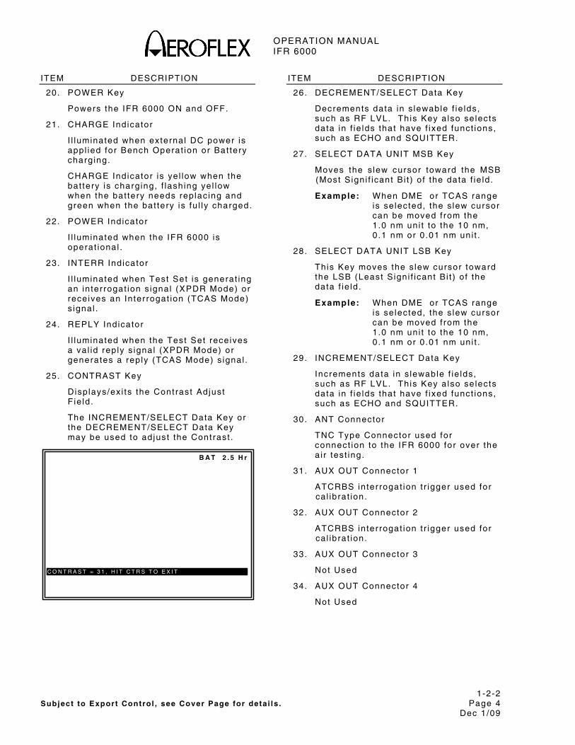
20. POWER Key
Powers the IFR 6000 ON and OFF.
21. CHARGE Indicator
I l luminated when external DC power is appl ied for Bench Operat ion or Bat tery charg ing.
CHARGE Indicator is ye l low when the bat tery is charg ing, f lash ing ye l low when the bat tery needs rep lac ing and green when the bat tery is fu l ly charged.
22. POWER Indicator
I l luminated when the IFR 6000 is operat ional .
23. INTERR Indicator
I l luminated when Test Set is generat ing an in ter rogat ion s ignal (XPDR Mode) or receives an In ter rogat ion (TCAS Mode) s ignal .
24. REPLY Indicator
I l luminated when the Test Set receives a va l id rep ly s ignal (XPDR Mode) or generates a rep ly (TCAS Mode) s ignal .
25. CONTRAST Key
Disp lays/ex i ts the Contrast Adjust F ie ld .
The INCREMENT/SELECT Data Key or the DECREMENT/SELECT Data Key may be used to ad just the Contrast .
B A T 2 . 5 H r
C O N T R A S T = 3 1 , H I T C T R S T O E X I T
ITEM DESCRIPTION
26. DECREMENT/SELECT Data Key
Decrements data in s lewable f ie lds, such as RF LVL. Th is Key a lso se lects data in f ie lds that have f ixed funct ions, such as ECHO and SQUITTER.
27. SELECT DATA UNIT MSB Key
Moves the s lew cursor toward the MSB (Most S ign i f icant B i t ) o f the data f ie ld .
Example: When DME or TCAS range is se lected, the s lew cursor can be moved f rom the 1 .0 nm uni t to the 10 nm, 0.1 nm or 0 .01 nm uni t .
28. SELECT DATA UNIT LSB Key
This Key moves the s lew cursor toward the LSB (Least S ign i f icant B i t ) o f the data f ie ld .
Example: When DME or TCAS range is se lected, the s lew cursor can be moved f rom the 1 .0 nm uni t to the 10 nm, 0.1 nm or 0 .01 nm uni t .
29. INCREMENT/SELECT Data Key
Increments data in s lewable f ie lds, such as RF LVL. Th is Key a lso se lects data in f ie lds that have f ixed funct ions, such as ECHO and SQUITTER.
30. ANT Connector
TNC Type Connector used for connect ion to the IFR 6000 for over the a i r test ing.
31. AUX OUT Connector 1
ATCRBS interrogat ion t r igger used for ca l ibrat ion.
32. AUX OUT Connector 2
ATCRBS interrogat ion t r igger used for ca l ibrat ion.
33. AUX OUT Connector 3
Not Used
34. AUX OUT Connector 4
Not Used

OPERATION MANUAL IFR 6000
1-2-2 Subject to Export Control , see Cover Page for deta i ls . Page 5
Dec 1/09
ITEM DESCRIPTION
35. USB HOST Connector
USB Jump Dr ive in ter face for sof tware update and test data dump (not act ive in f i rs t re lease) .
36. USB DEVICE Connector
Remote Contro l In ter face.
37. ALTITUDE ENCODER Connector
In ter face for external encoding a l t imeter .
38. AUX IN Connector
Not Used
39. RS-232 Connector
Used for remote contro l in ter face, sof tware update and test data dump.
40. REMOTE Connector
Used to in ter face wi th the IFR 6000.

OPERATION MANUAL IFR 6000
1-2-2 Subject to Export Control , see Cover Page for deta i ls . Page 6
Dec 1/09
05822
30
Di rect ional Antenna Figure 2
AUX OUT 1 AUX OUT 2
REMOTE
IFR 6000 BREAKOUT BOX51190 / 7005-5841-000
AUX OUT 3 AUX OUT 4
05815A
31 32 33 34
Breakout Box - Front V iew Figure 3

OPERATION MANUAL IFR 6000
1-2-2 Subject to Export Control , see Cover Page for deta i ls . Page 7
Dec 1/09
ALTITUDE ENCODERUSB HOST USB DEVICE AUX IN RS-232
05821A
35 36 37 38 39
Breakout Box - Top View
Figure 4
05821B
40
Breakout Box - Bot tom View
Figure 5
OPERATION MANUAL IFR 6000
1-2-2 Subject to Export Control , see Cover Page for deta i ls . Page 8
Dec 1/09
THIS PAGE INTENTIONALLY LEFT BLANK.
OPERATION MANUAL IFR 6000
1-2-3 Subject to Export Control , see Cover Page for deta i ls . Page 1
Dec 1/09
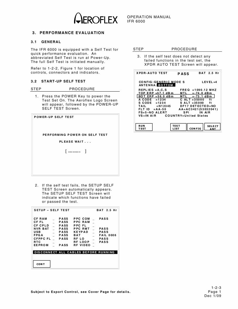
3. PERFORMANCE EVALUATION
3.1 GENERAL
The IFR 6000 is equipped wi th a Sel f Test for qu ick per formance evaluat ion. An abbrev iated Sel f Test is run at Power-Up. The fu l l Sel f Test is in i t ia ted manual ly .
Refer to 1-2-2, F igure 1 for locat ion of cont ro ls , connectors and ind icators .
3.2 START-UP SELF TEST
STEP PROCEDURE
1. Press the POWER Key to power the Test Set On. The Aerof lex Logo Screen wi l l appear , fo l lowed by the POWER-UP SELF TEST Screen.
P OW ER - U P S EL F T E ST
PE R F OR M IN G P OW E R ON SE L F T ES T
PL EA S E WA I T . . .
[ ******* * ]
2 . I f the se l f test fa i ls , the SETUP SELF TEST Screen automat ica l ly appears. The SETUP SELF TEST Screen wi l l ind icate which funct ions have fa i led or passed the test .
B A T 2 .5 H r
CON T
S ET U P – S EL F T E ST
C F R A M _ P A SS P PC C OM _ PA S S C F F L _ P A SS P PC R A M _ C F C P L D _ P A SS P PC F L _ N VR B AT _ P A SS P PC R M T _ PA S S U SB _ P A SS K E YP A D _ PA S S F PG A _ P A SS B A T _ F A IL 0 00 6 C F PP C F L _ P A SS R F L O _ PA S S R T C _ R F L OO P _ PA S S EE PR O M _ P A SS R F VI D EO _
D IS C ON N E CT A L L C A B L ES B E F OR E R U N N I NG
STEP PROCEDURE
3. I f the se l f test does not detect any fa i led funct ions in the test set , the XPDR AUTO TEST Screen wi l l appear .
B A T 2 .5 H r
R EPL IE S = A ,C , S F R E Q = 1 09 0 .1 2 M H Z T OP E R P =5 7 .1 d B m M T L = - 74 . 0 d B m BO T ER P = 5 6. 0 d B m M T L = - 73 . 1 d B m A C OD E = 1 2 34 C AL T = 3 50 0 0 f t S C OD E = 12 3 4 S A L T = 35 0 00 f t T A IL = N 1 23 45 D F 1 7 D ET EC T E D = NO F L T ID = A A - 5 0 A A = A C 3 42 1 (5 3 03 2 04 1 ) F S= 5 –N O A L E R T S PI IN AI R VS = IN A I R C O U N T R Y= U n i t ed St a t es
RUNT EST TES T
LIST
X PD R - A U T O T E ST
CON FIG
CO N F IG : GE N ER I C M OD E S AN T E N N A : B O T T OM
SELE CTA NT
P ASS
L EV EL =4

OPERATION MANUAL IFR 6000
1-2-3 Subject to Export Control , see Cover Page for deta i ls . Page 2
Dec 1/09
3.3 MANUAL SELF TEST
STEP PROCEDURE
1. Press SETUP Key unt i l the Setup-Genera l Screen is d isp layed.
B A T 2 .5 H r
PRE V PA RA M
S ET U P – G EN E R A L
H /W TO OLS
P W R DO W N : 10 m in s E R P U N I T S : d B m U NI T S : F EE T R E M OT E OP ER A T I ON : R S2 3 2
INFO
NEX T PA RA M
2 . Press H/W TOOLS Sof t Key to d isp lay the Hardware Tools Screen.
B A T 2 .5 H r
RS2 32
C AL
S ET U P – H A R D W A R E T OO L S
S /N 1 0 30 0 99 9 9 M U L T I - F U N C T IO N B O AR D R EV 0
R F B OA R D R EV 0 C P U B O A R D R E V 0
RET URN
SELF TES T
STEP PROCEDURE
3. Press SELF TEST Sof t Key to d isp lay the Sel f Test Screen.
B A T 2 .5 H r
RUN TES T
S ET U P – S EL F T E ST
D UMP IN FO
C F R A M _ P PC C OM _ C F F L _ P PC R A M _ C F C P L D _ P PC F L _ N VR B AT _ P PC R M T _ U SB _ K E YP A D _ F PG A _ B A T _ C F PP C F L _ R F I / F _ R T C _ R F M OD _ EE PR O M _
RET URN
D IS C ON N E CT A L L C A B L ES B E F OR E R U N N I NG
4 . Press RUN TEST Sof t Key to in i t ia te the Sel f Test .
5 . Ver i fy that a l l the modules/assembl ies pass the Sel f Test . I f the Sel f Test ind icates a fa i lure, contact Aerof lex for addi t ional in format ion:
AEROFLEX 10200 West York Wichi ta , KS 67215 U.S.A.
Phone: (800) 835-2350 FAX: (316) 524-2623 EMAIL: serv ice@aerof lex.com
AEROFLEX INTL LTD Uni ts 14/15 Monks Brook Indust r ia l Park , School Close Chandlers Ford, Hampshi re England A053 4RA
Phone: 44-2380-273722 FAX: 44-2380-254015

OPERATION MANUAL IFR 6000
1-2-4 Subject to Export Control , see Cover Page for deta i ls . Page 1
Dec 1/09
4. OPERATING PROCEDURES
4.1 GENERAL
This sect ion conta ins operat ing inst ruct ions for the IFR 6000. The IFR 6000 tests ATCRBS/MODE S Transponders, DME, TCAS, ADS-B, TIS and TIS-B. The IFR 6000 replaces the IFR ATC-600A, ATC-601 and TCAS-201.
Genera l procedures ident i fy the contro ls , connectors , ind icators and d isp lay screens used in ind iv idual test modes. For spec i f ic Uni t Under Test (UUT) Procedures, re fer to the UUT Manual .
Refer to 1-2-2, F igure 2 for locat ion of cont ro ls , connectors and ind icators .
The IFR 6000 Test Set prov ides ATCRBS/Mode S Transponder and DME Test capabi l i ty as s tandard modes.
Sof tware opt ions avai lab le are:
● TCAS I , I I , T IS (Traf f ic In format ion Serv ice) and TIS-B (Traf f ic In format ion Serv ice Broadcast ) .
● ADS-B (DO-260/A) and GICB ext racted DAP’s (Downl inked Ai rcraf t Parameters) .
The IFR 6000 uses four funct ional modes:
XPDR MODE
XPDR Mode prov ides f l ight l ine test capabi l i ty for ATCRBS and Mode S t ransponders us ing an Auto Test , a ser ies of tests d isp layed over severa l screens. A l l data normal ly requi red to ver i fy t ransponder operat ion in accordance wi th FAR 91.413, Par t 43, Appendix F, is d isp layed on one main Auto Test Screen.
Di f ferent c lasses of t ransponders are tested to bu i l t - in test l imi ts by se lect ion of conf igurat ion f i les . I f the c lass of t ransponder is unknown, gener ic conf igurat ion f i les are prov ided for ATCRBS and Mode S t ransponders that apply the widest system l imi ts .
Mode S Transponder leve l is automat ica l ly determined. European Enhanced Surve i l lance test capabi l i ty a l lows decode and d isp lay of GICB der ived BDS regis ter contents (pr imary parameters on ly) .
ADS-B prov ides f l ight l ine test capabi l i ty for rece iv ing, decoding and d isp lay ing fu l l DO-260/A DF17 extended squi t ter t ransmiss ions f rom Mode S t ransponders or DF18 extended squi t ters f rom 1090 MHz emi t ters . Capabi l i ty to generate fu l l DO-260/A DF17/18 extended squi t ter t ransmiss ions for test ing ADS-B receivers is prov ided. A GICB mode decodes and d isp lays a l l Enhanced Surve i l lance BDS regis ter contents .
NOTE: ADS-B operates as an XPDR submode.
NOTE: NUCp (DO-260) is not suppor ted. NIC/NAC/SIL (DO-260/A) is suppor ted.
DME MODE
DME Mode prov ides f l ight l ine test capabi l i ty for Dis tance Measur ing Equipment In ter rogators. A l l parameters normal ly requi red for DME test ing are d isp layed on one main screen. UUT in ter rogat ion parameters are c lear ly d isp layed in conjunct ion wi th Test Set rep ly parameters.
TCAS MODE
TCAS Mode prov ides f l ight l ine test capabi l i ty for TCAS I and I I . ATCRBS and Mode S in t ruders are s imulated, a l lowing the generat ion of prox imi ty , TA and RA f l ight deck annunciat ions. TCAS Inter rogator parametr ic measurements are d isp layed.
T IS Prov ides a f ive a i rcraf t s ta t ic f l ight s imulat ion, us ing the Comm A protocol , to test the TIS (Traf f ic In format ion Serv ice) .
T IS-B prov ides a f ive a i rcraf t s ta t ic f l ight s imulat ion, us ing DF18 extended squi t ter broadcasts , for test ing TIS-B (Traf f ic In format ion Serv ice Broadcast ) systems.
NOTE: TIS and TIS-B operate as TCAS sub modes.
NOTE: T IS-B is not prov ided in the second re lease of the TCAS opt ion.
SETUP MODE
SETUP Mode funct ion sets var ious parameters used in test ing, conf igurat ion and memory s torage for each funct ional mode.
OPERATION MANUAL IFR 6000
1-2-4 Subject to Export Control , see Cover Page for deta i ls . Page 2
Dec 1/09
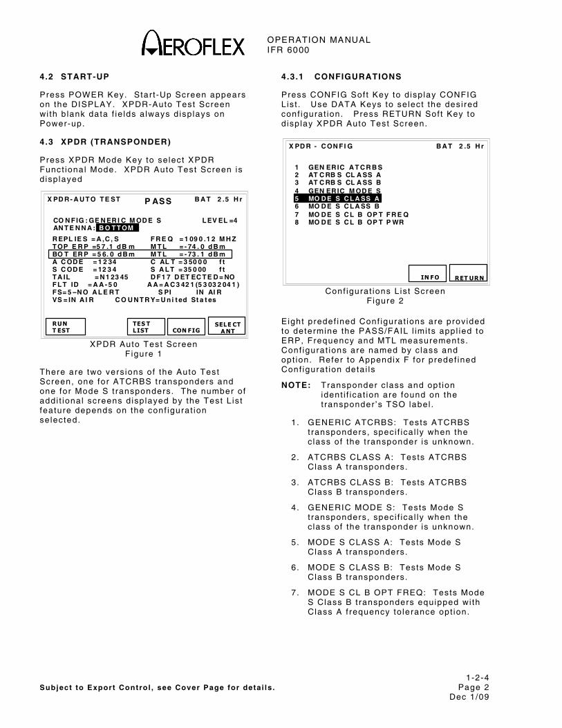
4.2 START-UP
Press POWER Key. Star t -Up Screen appears on the DISPLAY. XPDR-Auto Test Screen wi th b lank data f ie lds a lways d isp lays on Power-up.
4.3 XPDR (TRANSPONDER)
Press XPDR Mode Key to se lect XPDR Funct ional Mode. XPDR Auto Test Screen is d isp layed
B A T 2 .5 H r
R EPL IE S = A ,C , S F R E Q = 1 09 0 .1 2 M H Z T OP E R P =5 7 .1 d B m M T L = - 74 . 0 d B m BO T ER P = 5 6. 0 d B m M T L = - 73 . 1 d B m A C OD E = 1 2 34 C AL T = 3 50 0 0 f t S C OD E = 12 3 4 S A L T = 35 0 00 f t T A IL = N 1 23 45 D F 1 7 D ET EC T E D = NO F L T ID = A A - 5 0 A A = A C 3 42 1 (5 3 03 2 04 1 ) F S= 5 –N O A L E R T S PI IN AI R VS = IN A I R C O U N T R Y= U n i t ed St a t es
RUN T EST TES T
LIST
X PD R - A U T O T E ST
CON FIG
CO N F IG : GE N ER I C M OD E S AN T E N N A : B O T T OM
SELE CTA NT
P ASS
L EV EL =4
XPDR Auto Test Screen F igure 1
There are two vers ions of the Auto Test Screen, one for ATCRBS t ransponders and one for Mode S t ransponders. The number of addi t ional screens d isp layed by the Test L is t feature depends on the conf igurat ion se lected.
4.3.1 CONFIGURATIONS
Press CONFIG Sof t Key to d isp lay CONFIG L is t . Use DATA Keys to se lect the des i red conf igurat ion. Press RETURN Sof t Key to d isp lay XPDR Auto Test Screen.
B A T 2 .5 H r
X PD R - C ON F I G
IN F O
1 GEN ER IC A T C R B S 2 AT C RB S CL A SS A 3 AT C RB S CL A SS B 4 GEN ER IC M OD E S 5 MO D E S C L A SS A 6 MO D E S C L A SS B 7 MO D E S C L B OP T F R E Q 8 MO D E S C L B OP T P WR
RET URN
Conf igurat ions L is t Screen F igure 2
Eight predef ined Conf igurat ions are prov ided to determine the PASS/FAIL l imi ts appl ied to ERP, Frequency and MTL measurements. Conf igurat ions are named by c lass and opt ion. Refer to Appendix F for predef ined Conf igurat ion deta i ls
NOTE: Transponder c lass and opt ion ident i f icat ion are found on the t ransponder ’s TSO label .
1 . GENERIC ATCRBS: Tests ATCRBS t ransponders, spec i f ica l ly when the c lass of the t ransponder is unknown.
2. ATCRBS CLASS A: Tests ATCRBS Class A t ransponders.
3. ATCRBS CLASS B: Tests ATCRBS Class B t ransponders.
4 . GENERIC MODE S: Tests Mode S t ransponders, spec i f ica l ly when the c lass of the t ransponder is unknown.
5. MODE S CLASS A: Tests Mode S Class A t ransponders.
6 . MODE S CLASS B: Tests Mode S Class B t ransponders.
7 . MODE S CL B OPT FREQ: Tests Mode S Class B t ransponders equipped wi th Class A f requency to lerance opt ion.

OPERATION MANUAL IFR 6000
1-2-4 Subject to Export Control , see Cover Page for deta i ls . Page 3
Dec 1/09
8. MODE S CL B OPT PWR: Tes ts Mode S Class B t ransponders equipped wi th Class A power opt ion.
NOTE: Level detect ion is automat ic when running a test .
Press INFO Sof t Key to d isp lay XPDR INFO Screen. XPDR INFO Screen d isp lays the PASS/FAIL l imi ts for se lected Conf igurat ion.
B A T 2 .5 H r
T ES T PA R A M ET R I C S T R A N SM IT T ER PO WE R 48 .5 - 5 7. 0 d B m R EC E IV ER MT L - 74 + / - 3 d B m T x F R EQ 10 9 0 + /- 3 M H z
X PD R – IN F O
CO N F IG = GE NE R I C M OD E S
RETUR N
L E VE L = ?
XPDR Informat ion Screen F igure 3
4.3.2 SETUP
SETUP XPDR
Setup XPDR Screen conta ins parameters which determine operat ional character is t ics of the XPDR Funct ional Mode. Unless otherwise s tated, last used va lues are reta ined on Power-up.
NOTE: Enter Setup Screen in format ion before conduct ing test operat ions.
B A T 2 .5 H r
PR EVPA RA M
S ET U P - XP D R
DI AG
A NT EN N A : B O T T OM R F P OR T : A N T E N N A A N T R A N GE A N T H EI GH T T OP : 5 0. 0 m 1 0 .0 m B OT T O M : 5 0. 0 m 0 .0 m D IR CA B L E L OS S: 1 . 3 d B A N T GA I N ( d B i) A NT C A B L E :6 F T 1. 03 G Hz : 7 .1 A NT C A B L E L O SS : 1. 7 d B 1. 09 G Hz : 6 .1 U UT A D D R E SS :A U T O M A N U A L A A: 1 2 34 5 6 PW R L I M : F A R 4 3 DI V ER S IT Y T E ST : O N C H EC K C AP : Y E S
TES TDA TA
NEX T P ARA M
Setup XPDR Screen F igure 4
STEP PROCEDURE
1. Press SETUP Sof t Key to d isp lay SETUP-XPDR Screen (1-2-4, F igure 1) .
2 . Set the parameters by press ing NEXT PARAM. Press PREV PARAM to se lect the f ie ld . Use DATA Keys to s lew the data. Parameters are:
● ANTENNA:
TOP or BOTTOM
● RF PORT:
Selects ANTENNA (ANT CONNECTOR) or DIRECT CONNECT v ia RF I /O Connector .
● DIRECT CABLE LOSS:
Entered in dB, f igure (at 1090 MHz) marked on suppl ied RF coax ia l cable.
NOTE: Cable loss range 0.0 to 9 .9 dB.

OPERATION MANUAL IFR 6000
1-2-4 Subject to Export Control , see Cover Page for deta i ls . Page 4
Dec 1/09
STEP PROCEDURE
● ANT CABLE:
Select ions USER DEFINED, 1 FT, 6 FT, 25 FT, 50 FT, 60 FT.
When USER DEFINED selected, cable loss may be manual ly entered by the user in ANT CABLE LOSS f ie ld . When 1, 6 , 25, 50 or 60 feet is se lected, ANT CABLE LOSS f ie ld is automat ica l ly ca lcu la ted.
ANT CABLE select ion of 1 , 6 , 25, 50 or 60 feet resul ts in 0 , 0 , 68, 138 and 184 ns of de lay.
● ANT CABLE LOSS:
Disp lays antenna cable loss in dB (at 1090 MHZ). I f user def ined, normal ly th is is set once, f igure marked on suppl ied RF coax ia l cab le
NOTE: Cable loss range 0.0 to 9 .9 dB.
I f preset length 1, 6 , 25, 50 or 60 feet is se lected, then cable loss in dB is automat ica l ly ca lcu la ted and d isp layed.
NOTE: Based on Aerof lex suppl ied cables, (25 and 50 foot cables opt ional )
NOTE: 25 and 50 foot cable se lect ion compensates for de lay of Aerof lex opt ional cables.
● ANT GAIN:
Entered in dBi , ga in f igures for 1030 and 1090 MHz marked on suppl ied Di rect ional Antenna.
NOTE: Antenna gain range 0.0 to 20.9 dB.
● ANT RANGE:
Test Set Antenna to t ransponder antenna hor izonta l range. Enter parameters for BOTTOM and TOP antenna i f ins ta l la t ion has d ivers i ty capabi l i ty .
NOTE: Antenna Range is 6 to 250 f t or 2 .0 to 75.0 m. UNITS parameter on SETUP-GENERAL Screen determines feet or meters (1-2-4, F igure 11) .
STEP PROCEDURE
● PWR LIM:
FAR 43 OR MOD43. FAR 43 uses l imi ts in accordance wi th FAR 91.413, Par t 43, Appendix F. MOD 43 removes upper ERP l imi ts and lower MTL l imi ts .
● CHECK CAP:
YES or NO. I f YES (defaul t ) is se lected, BDS 1,7/1,8/1,9 is ver i f ied to conf i rm avai lab i l i ty o f :
BDS 0,5 BDS 0,6 BDS 0,7 BDS 0,8 BDS 0,9 BDS 1,D BDS 1,E BDS 1,F BDS 2,0 BDS 2,1 BDS 3,0 BDS 4,0 BDS 4,1 BDS 4,2 BDS 4,3 BDS 5,0 BDS 6,0 BDS 6,1 BDS 6,2 BDS 6,3
I f BDS 1,7/1,8/1,9 repor ts a par t icu lar BDS is not avai lab le, the data is b lanked a longs ide the respect ive BDS in the Enhanced Survei l lance Screen, or GICB screens.
I f NO is se lected, BDS 1,7/1,8/1,9 is not ver i f ied and the Test Set wi l l ext ract the BDS and d isp lay content .
NOTE: Some t ransponders rep ly to BDS requests even though BDS 1,7/1,8/1,9 repor ts they are not ava i lab le .

OPERATION MANUAL IFR 6000
1-2-4 Subject to Export Control , see Cover Page for deta i ls . Page 5
Dec 1/09
STEP PROCEDURE
● UUT ADDRESS:
MANUAL or AUTO (defaul ts to AUTO on power-up) . AUTO select ion Mode S address is obta ined v ia ATCRBS/Mode S Al l Cal l (FAR Par t 43, Appendix F approved method) .
On loss of ATCRBS/Mode S Al l Cal l rep ly ( i .e . , UUT p laced in ground s tate) tests a l ready running cont inue to use last ATCRBS/ Mode S Al l Cal l obta ined address. AUTO uses manual ly entered address i f no rep ly is rece ived.
NOTE: ICAO amendment 77 t ransponders on ly rep l ies to Mode S d iscrete in ter rogat ions when insta l la t ion is in ground state.
● MANUAL ADDRESS:
A s ix d ig i t HEX address is entered i f UUT ADDRESS: MANUAL is se lected.
● DIVERSITY TEST:
ON or OFF. I f test ing t ransponders wi th s ing le antenna systems, se lect OFF.
NOTE: I f Divers i ty Iso la t ion Test is enabled, ensure Antenna Shie ld is f i t ted to top or bot tom UUT antenna pr ior to running test . Refer to Appendix J for Antenna Shie ld mount ing procedure.
3 . Press XPDR Mode Key to re turn to XPDR Auto Test Screen.
STEP PROCEDURE
Software Update Procedure Via USB:
1. Sof tware must be loaded onto a FAT 16 USB Flash Memory s t ick . Sof tware updates may be downloaded f rom product data sect ion on the www.aerof lex .com webs i te . Note: on ly one vers ion of sof tware may res ide on the root d i rectory of the F lash Memory s t ick .
2 . Connect IFR 6000 breakout box to IFR 6000. Inser t F lash Memory s t ick in USB por t and Press Power key to power un i t . Sof tware load process is automat ic .
3 . When sof tware load is complete, remove F lash Memory s t ick .
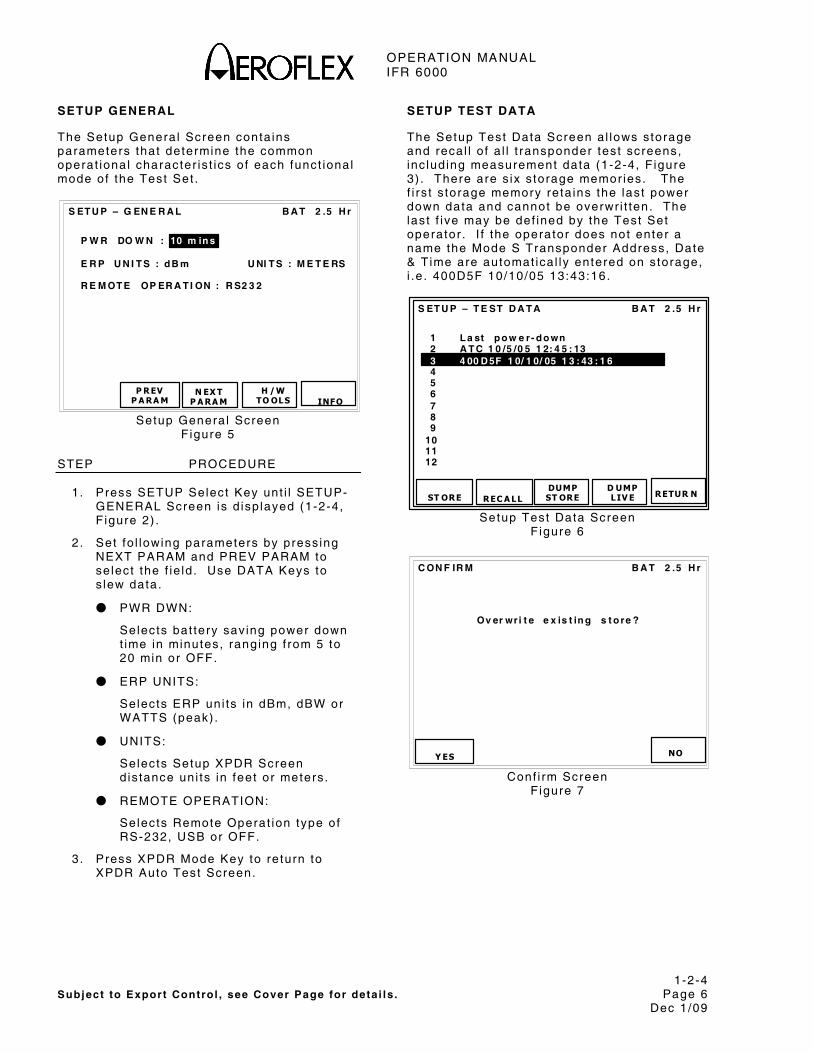
OPERATION MANUAL IFR 6000
1-2-4 Subject to Export Control , see Cover Page for deta i ls . Page 6
Dec 1/09
SETUP GENERAL
The Setup Genera l Screen conta ins parameters that determine the common operat ional character is t ics o f each funct ional mode of the Test Set .
B A T 2 .5 H r
P R EV P A RA M
S ET U P – G EN E R A L
H /W TO OLS
P W R DO W N : 10 m in s E R P U N I T S : d B m U NI T S : M E T E RS R E M OT E OP ER A T I ON : R S2 3 2
INFO
N EX T P A RA M
Setup Genera l Screen F igure 5
STEP PROCEDURE
1. Press SETUP Select Key unt i l SETUP- GENERAL Screen is d isp layed (1-2-4, F igure 2) .
2 . Set fo l lowing parameters by press ing NEXT PARAM and PREV PARAM to se lect the f ie ld . Use DATA Keys to s lew data.
● PWR DWN:
Selects bat tery sav ing power down t ime in minutes, ranging f rom 5 to 20 min or OFF.
● ERP UNITS:
Selects ERP uni ts in dBm, dBW or WATTS (peak) .
● UNITS:
Selects Setup XPDR Screen d is tance uni ts in feet or meters .
● REMOTE OPERATION:
Selects Remote Operat ion type of RS-232, USB or OFF.
3. Press XPDR Mode Key to re turn to XPDR Auto Test Screen.
SETUP TEST DATA
The Setup Test Data Screen a l lows s torage and recal l o f a l l t ransponder test screens, inc lud ing measurement data (1-2-4, F igure 3) . There are s ix s torage memor ies. The f i rs t s torage memory reta ins the last power down data and cannot be overwr i t ten. The last f ive may be def ined by the Test Set operator . I f the operator does not enter a name the Mode S Transponder Address, Date & T ime are automat ica l ly entered on s torage, i .e . 400D5F 10/10/05 13:43:16.
1 L a st p o w e r- d o wn 2 A T C 1 0 /5 /0 5 1 2: 4 5 : 13 3 4 00 D 5F 1 0/ 1 0/ 05 1 3 : 43 : 1 6
4 5
6 7 8 9
10 11 12
B A T 2 .5 H r
ST ORE
DUMP ST ORE
S ET U P – T E ST D A T A
D UMP LIV E REC A LL
S
RETUR N
Setup Test Data Screen F igure 6
B A T 2 .5 H r
Y ES
C ON F IR M
Ov er wr i t e e x is t in g s t o re ?
NO
Conf i rm Screen F igure 7
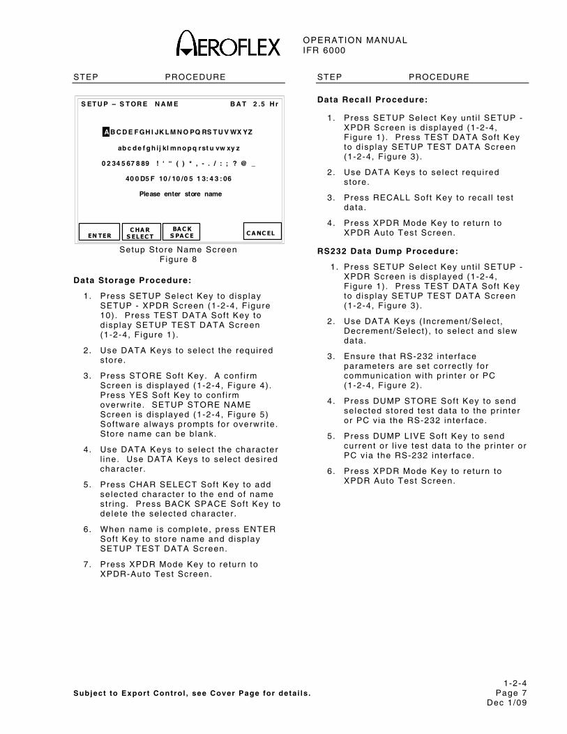
OPERATION MANUAL IFR 6000
1-2-4 Subject to Export Control , see Cover Page for deta i ls . Page 7
Dec 1/09
STEP PROCEDURE
B A T 2 .5 H r
EN TER
BA C K S PA C E
S ET U P – S T OR E N A M E
A B C D E F GH I JK L M N O PQ RS T U V WX YZ
ab c d e f g h ij kl mn o p q rst u vw xy z
0 2 34 5 67 8 89 ! ‘ “ ( ) * , - . / : ; ? @ _
40 0 D5 F 10 / 10 /0 5 1 3: 4 3 : 06
Please enter store name
C HA R S ELEC T
C A NC EL
Setup Store Name Screen F igure 8
Data Storage Procedure:
1. Press SETUP Select Key to d isp lay SETUP - XPDR Screen (1-2-4, F igure 10) . Press TEST DATA Sof t Key to d isp lay SETUP TEST DATA Screen (1-2-4, F igure 1) .
2 . Use DATA Keys to se lect the requi red s tore.
3 . Press STORE Sof t Key. A conf i rm Screen is d isp layed (1-2-4, F igure 4) . Press YES Sof t Key to conf i rm overwr i te . SETUP STORE NAME Screen is d isp layed (1-2-4, F igure 5) Sof tware a lways prompts for overwr i te . Store name can be b lank.
4 . Use DATA Keys to se lect the character l ine. Use DATA Keys to se lect des i red character .
5 . Press CHAR SELECT Sof t Key to add se lected character to the end of name s t r ing. Press BACK SPACE Sof t Key to de lete the se lected character .
6 . When name is complete, press ENTER Sof t Key to s tore name and d isp lay SETUP TEST DATA Screen.
7 . Press XPDR Mode Key to re turn to XPDR-Auto Test Screen.
STEP PROCEDURE
Data Recal l Procedure:
1. Press SETUP Select Key unt i l SETUP - XPDR Screen is d isp layed (1-2-4, F igure 1) . Press TEST DATA Sof t Key to d isp lay SETUP TEST DATA Screen (1-2-4, F igure 3) .
2 . Use DATA Keys to se lect requi red s tore.
3 . Press RECALL Sof t Key to reca l l tes t data.
4 . Press XPDR Mode Key to re turn to XPDR Auto Test Screen.
RS232 Data Dump Procedure:
1 . Press SETUP Select Key unt i l SETUP - XPDR Screen is d isp layed (1-2-4, F igure 1) . Press TEST DATA Sof t Key to d isp lay SETUP TEST DATA Screen (1-2-4, F igure 3) .
2 . Use DATA Keys ( Increment /Select , Decrement /Select ) , to se lect and s lew data.
3 . Ensure that RS-232 in ter face parameters are set correct ly for communicat ion wi th pr in ter or PC (1-2-4, F igure 2) .
4 . Press DUMP STORE Sof t Key to send se lected s tored test data to the pr in ter or PC v ia the RS-232 in ter face.
5 . Press DUMP LIVE Sof t Key to send current or l ive test data to the pr in ter or PC v ia the RS-232 in ter face.
6 . Press XPDR Mode Key to re turn to XPDR Auto Test Screen.
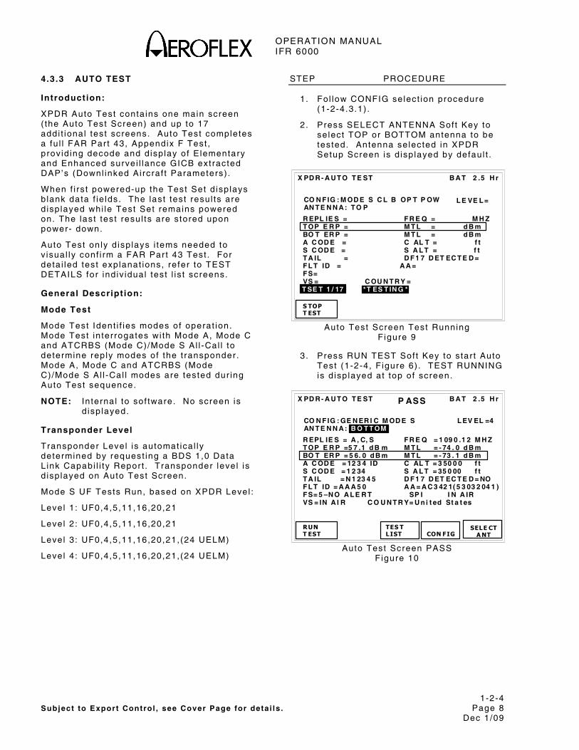
OPERATION MANUAL IFR 6000
1-2-4 Subject to Export Control , see Cover Page for deta i ls . Page 8
Dec 1/09
4.3.3 AUTO TEST
Introduction:
XPDR Auto Test conta ins one main screen ( the Auto Test Screen) and up to 17 addi t ional test screens. Auto Test completes a fu l l FAR Par t 43, Appendix F Test , prov id ing decode and d isp lay of E lementary and Enhanced surve i l lance GICB ext racted DAP’s (Downl inked Ai rcraf t Parameters) .
When f i rs t powered-up the Test Set d isp lays b lank data f ie lds. The last test resu l ts are d isp layed whi le Test Set remains powered on. The last test resul ts are s tored upon power- down.
Auto Test on ly d isp lays i tems needed to v isual ly conf i rm a FAR Par t 43 Test . For deta i led test explanat ions, re fer to TEST DETAILS for ind iv idual test l is t screens.
General Descript ion:
Mode Test
Mode Test Ident i f ies modes of operat ion. Mode Test in ter rogates wi th Mode A, Mode C and ATCRBS (Mode C)/Mode S Al l -Cal l to determine rep ly modes of the t ransponder . Mode A, Mode C and ATCRBS (Mode C)/Mode S Al l -Cal l modes are tested dur ing Auto Test sequence.
NOTE: In ternal to sof tware. No screen is d isp layed.
Transponder Level
Transponder Level is automat ica l ly determined by request ing a BDS 1,0 Data L ink Capabi l i ty Repor t . Transponder leve l is d isp layed on Auto Test Screen.
Mode S UF Tests Run, based on XPDR Level :
Level 1 : UF0,4,5,11,16,20,21
Level 2 : UF0,4,5,11,16,20,21
Level 3 : UF0,4,5,11,16,20,21, (24 UELM)
Level 4 : UF0,4,5,11,16,20,21, (24 UELM)
STEP PROCEDURE
1. Fo l low CONFIG select ion procedure (1-2-4.3.1) .
2 . Press SELECT ANTENNA Sof t Key to se lect TOP or BOTTOM antenna to be tested. Antenna se lected in XPDR Setup Screen is d isp layed by defaul t .
R EPL IE S = F R E Q = M H Z T OP E R P = M T L = d B m BO T ER P = M T L = d B m A C OD E = C AL T = f t S C OD E = S A L T = f t T A IL = D F 1 7 D ET EC T E D = F L T ID = A A = F S= VS = C OU N T R Y = T SE T 1 / 17 *T ES T IN G *
CO N F IG : M OD E S C L B OP T P OW AN T E N N A : T O P
B A T 2 .5 H r
S TOPT EST
X PD R - A U T O T E ST
L E VE L =
Auto Test Screen Test Running F igure 9
3. Press RUN TEST Sof t Key to s tar t Auto Test (1-2-4, F igure 6) . TEST RUNNING is d isp layed at top of screen.
B A T 2 .5 H r
R EPL IE S = A , C, S F R E Q = 1 09 0 .1 2 M H Z T OP E R P =5 7 .1 d B m M T L = - 74 . 0 d B m BO T ER P = 5 6. 0 d B m M T L = - 73 . 1 d B m A C OD E = 12 3 4 ID C AL T = 3 50 0 0 f t S C OD E = 1 2 34 S A L T = 35 0 00 f t T A IL = N 1 23 4 5 D F 1 7 D ET EC T E D = NO F L T ID = A A A 5 0 A A = A C 3 42 1( 5 3 03 2 04 1 ) F S= 5 –N O A L E R T SP I I N A IR VS = IN A I R C O U N T R Y= U n i t ed St a t es
RUNT EST TES T
LIST
X PD R - A U T O T E ST
CON FIG
CO N F IG : GE N ER I C M OD E S AN T E N N A : B O T T OM
SELE CTA NT
P ASS
L EV EL =4
Auto Test Screen PASS Figure 10

OPERATION MANUAL IFR 6000
1-2-4 Subject to Export Control , see Cover Page for deta i ls . Page 9
Dec 1/09
STEP PROCEDURE
4. Auto Test completes and d isp lays Parameters tes ted (1-2-4, F igure 7) . Warn ings/Errors are ident i f ied by an arrow symbol to le f t o f the i tem.
The Parameters d isp layed are:
Regulatory Test Requirements
TESTS IDENTIFIER SYMBOLS
♦ FAA FAR 91.413, Par t 43, Appendix F
• Other Civ i l Av ia t ion Author i ty Requi rement
♣ Eurocontro l /JAA (Proposed
Test Ident i f ier Symbols Table 1
Auto Test Detai ls:
♦REPLIES: Transponder Modes repl ied to A,C,S
♦FREQ: Transponder TX f requency in MHz
♦TOP ERP: Top t ransponder antenna Ef fect ive Radiated Power in dBm, dBW or peak
NOTE: Uni ts se lected in SETUP-GENERAL Screen.
♦TOP MTL: Top t ransponder antenna Min imum Tr igger Level
♦BOT ERP: Bot tom t ransponder antenna Ef fect ive Radiated Power in dBm, dBW or peak.
NOTE: Uni ts se lected in SETUP-GENERAL Screen.
♦BOTTOM MTL: Bot tom t ransponder antenna Min imum Tr igger Level
♦A CODE: Mode A 4096 squawk code. Presence of Ident (SPI) pu lse ind icated by d isp lay of ‘ ID’ a f ter the squawk code.
♦S CODE: Mode S 4096 Ident i ty Code. Presence of Ident (SPI) pu lse ind icated by d isp lay of ‘ ID’ a f ter the squawk code (obta ined f rom DF5)
NOTE: The Mode A code is compared wi th Mode S code. Modes A and S codes Pass when in agreement .
STEP PROCEDURE
♦C ALT: Mode C a l t i tude d isp layed (100 f t reso lut ion)
♦S ALT: Mode S a l t i tude d isp layed (25 or 100 feet resolut ion, obta ined f rom DF4)
NOTE: Mode C a l t i tude is compared to Mode S a l t i tude. Modes C and S a l t i tudes Pass when in agreement o f 100 f t .
♦TAIL: A i rcraf t ta i l number decoded f rom Mode S d iscrete address (obta ined f rom Mode S Al l Cal l DF11)
NOTE: Some countr ies have encoded the a i rcraf t ta i l number in to the Mode S d iscrete address. Refer to Appendix G for l is t o f countr ies suppor ted. I f not suppor ted only the country is d isp layed.
COUNTRY: Decoded f rom the Mode S d iscrete address (obta ined f rom Mode S Al l Cal l DF11).
DF17 DETECTED: Ind icates the presence of DF17 extended squi t ter .
NOTE: ADS-B opt ion is requi red to decode and d isp lay DF17 squi t ter content .
♣FLT ID: E ight Character ICAO Fl ight ID
♦AA: A i rcraf t Address (Mode S d iscrete address) d isp layed in HEX and (OCTAL)
♣FS: F l ight Status. The number preceding the text ident i f ies the RTCA DO-181C FS code ass ignment . Ind icat ions are:
ALERT, NO ALERT, SPI , NO SPI, AIRBORNE, ON GROUND (obta ined f rom DF0).
♣VS: Ver t ica l Status e i ther ON GND or IN AIR (obta ined f rom DF0)
Testing FS (Fl ight Status) and VS (Vert ical Status):
ICAO Amendment 77 t ransponders on ly rep ly to Mode S d iscrete in ter rogat ions when insta l la t ion is in ground state. Refer to Setup for UUT ADDRESS set t ings (para 1-2-4.3.2) .

OPERATION MANUAL IFR 6000
1-2-4 Subject to Export Control , see Cover Page for deta i ls . Page 10
Dec 1/09
STEP PROCEDURE
Auto Test Screen examples:
ATCRBS CLASS B conf igurat ion se lected wi th FAIL ind icat ion (Only ATCRBS parameters d isp layed) .
B A T 2 .5 H r
R EPL IE S = A F R E Q =1 0 90 . 12 M H Z BO T ER P = 5 6. 0 d B m M T L = - 73 . 1 d B m A C OD E = 1 2 34 I D C AL T = 3 05 0 0 f t
RUN T ES T T ES T
LIS T
X PD R - A U T O T E ST
CON FIG
CO N F IG : A T C R B S CL A SS B
F AIL
L EV EL = N / A
ATCRBS Class B Auto Test Screen F igure 11
GENERIC ATCRBS conf igurat ion se lected wi th NO REPLY ind icat ion (No Reply From Transponder) .
B A T 2 .5 H r
R EPL IE S = F R E Q = M H Z BO T ER P = d B m M T L = d B m A C OD E = C AL T =
RUN T ES T T ES T
LIS T
X PD R - A U T O T E ST
CON FIG
CO N F IG : GE N ER I C A T C R B S
N O R E PL Y
L EV EL = N / A
Gener ic ATCRBS Auto Test Screen F igure 12
4.3.4 TEST LIST
Introduction:
Auto Test Screen is the pr imary test screen. The complete Auto Test conta ins up to 17 addi t ional test screens.
The Test Set d isp lays b lank data f ie lds when f i rs t powered-up. Whi le the Test Set remains powered the last test resu l ts are d isp layed.
STEP PROCEDURE
1. Press TEST LIST Sof t Key to d isp lay Test L is t . When a Mode S conf igurat ion is se lected the test l is t is d isp layed over two screens (1-2-4, F igure 8) . When an ATCRBS conf igurat ion is se lected the test l is t is d isp layed on one screen (1-2-4, F igure 9) .
2. Use DATA Keys to se lect des i red test . Press SELECT TEST Sof t Key to d isp lay se lected test .
3 . Press RETURN Sof t Key to d isp lay XPDR Auto Test Screen.
4 . Press RUN TEST Sof t Key to s tar t tes t .
5 . Press STOP TEST Sof t Key to s top test .
6 . Press NEXT TEST Sof t Key to d isp lay the next test .
7 . Press PREV TEST Sof t Key to d isp lay the prev ious test .
8 . Press RETURN Sof t Key to d isp lay the test l is t and choose des i red test .
NOTE: The test runs unt i l s topped. Each pass through the test sequence updates the PASS/FAIL ind icat ion.

OPERATION MANUAL IFR 6000
1-2-4 Subject to Export Control , see Cover Page for deta i ls . Page 11
Dec 1/09
1 A /C D EC D R / SL S - PA S S 2 A /C F 1 /F 2 S PA C E /W ID T H - PA S S 3 PO W ER /F R EQ - PA S S 4 S A L L - C A L L - PA S S 5 S R EP L Y T I MI N G - PA S S 6 S R EP L Y - PA S S 7 U F 0 - PA S S 8 U F 4 - PA S S 9 U F 5 - PA S S 1 0 UF 11 - PA S S 1 1 UF 16 - PA S S 1 2 UF 20 - PA S S
B A T 2 .5 H r
X PD R – T ES T L IST
RET URN
SELE CT TES T
N EX T P A GE
B A T 2 .5 H r
X PD R – T ES T L IST
6 S R EP L Y - PA S S 7 U F 0 - PA S S 8 U F 4 - PA S S 9 U F 5 - PA S S 1 0 UF 11 - PA S S 1 1 UF 16 - PA S S 1 2 UF 20 - PA S S 1 3 UF 21 - PA S S 1 4 UF 24 - PA S S 1 5 EL E M EN T A R Y S U R V 1 - PA S S 1 6 EL E M EN T A R Y S U R V 2 - PA S S 1 7 EN H A N C ED SU R V - PA S S
RET URN
SELE CT TES T
N EX T P A GE
XPDR Test L is t Mode S F igure 13
B A T 2 .5 H r
X PD R – T ES T L IST
1 A/ C DE C D R /S L S - PA S S 2 A/ C F 1 / F 2 SP A C E/ W ID T H - PA S S 3 POW E R /F R E Q - PA S S
RET URN
SELE CT TES T
N EX T P A GE
XPDR Test L is t ATCRBS Figure 14
B A T 2 .5 H r
RUNT ES T
PR EV T ES T
X PD R – A /C D EC D R /S L S
NEX TT EST
A C OD E = 26 2 0 I D EN T A4 A 2 A 1 B 4 B 2 B 1 C 4 C 2 C 1 D 4 D 2 D1
D EC OD E R I N N ER L OW A = PA S S C = PA S S D EC OD E R I N N ER H IG H A = PA S S C = PA S S D EC OD E R O U T ER L OW A = PA S S C = PA S S D EC OD E R O U T ER H IG H A = PA S S C = PA S S SL S 0 d B A = PA S S C = PA S S SL S - 9 d B A = PA S S C = PA S S
RET URN
P A S S
C A L T = 10 0 0 00 f t A4 A 2 A 1 B 4 B 2 B 1 C 4 C 2 C 1 D 4 D 2
XPDR A/C Decoder /SLS Test Screen F igure 15
XPDR A/C Decoder/SLS Test
XPDR A/C Decoder /SLS Test (1-2-4, F igure 10) per forms these funct ions:
♦Ver i f ies inner and outer windows for Mode A and C in ter rogat ions
♦Ver i f ies the SLS per formance for Mode A and C in ter rogat ions
♦Displays Mode A Squawk Code, Ident (SPI) and code b inary b i ts .
♦Decodes and d isp lays the Mode C a l t i tude in feet and code b inary b i ts .
NOTE: Binary b i ts ver i fy i f spec i f ic cont ro l l ines are correct .
Decoder
The Test Set in ter rogates wi th va l id Mode A and C in ter rogat ions, +6 dB above MTL.
Nominal spac ing, P1 to P3, 8 μs for Mode A and 21 μs for Mode C. The test dev iates the pu lse spac ings as fo l lows:
Sets P1 to P3 pu lse spac ing to inner h igh "must rep ly" va lues (8.2 μs for Mode A and 21.2 μs for Mode C). The test ind icates PASS i f percent rep l ies are ≥90% or FAIL i f percent rep l ies are <90%. An arrow ident i f ies FAIL.
Sets P1 to P3 pu lse spac ing to inner low "must rep ly" va lues (7.8 μs for Mode A and 20.8 μs for Mode C). The test ind icates PASS i f percent rep l ies are ≥90% or FAIL i f percent rep l ies are <90%. An arrow ident i f ies FAIL.

OPERATION MANUAL IFR 6000
1-2-4 Subject to Export Control , see Cover Page for deta i ls . Page 12
Dec 1/09
Sets P1 to P3 pu lse spac ing to outer h igh "must not rep ly" va lues (9.0 μs for Mode A and 22 μs for Mode C). The test ind icates PASS i f percent rep l ies are <10% or FAIL i f percent rep l ies are ≥10%. An arrow ident i f ies FAIL.
Sets P1 to P3 pu lse spac ing to outer low "must not rep ly" va lues (7.0 μs for Mode A and 20 μs for Mode C). The test ind icates PASS i f percent rep l ies are <10% or FAIL i f percent rep l ies are ≥10%. An arrow ident i f ies FAIL.
SLS
The Test Set in ter rogates wi th Mode A and C in ter rogat ions inc lud ing the P2 SLS pulse. When P2 leve l is set a t -9 dB and rep l ies are ≥90%, the tes t ind icates PASS. I f rep l ies are <90%, the test ind icates FAIL.
When P2 leve l is set a t 0 dB and rep l ies are ≥1%, the test ind icates FAIL. I f rep l ies are <1%, the tes t ind icates PASS.
NOTE: Because in ter rogat ion wi th SLS at -9 dB is sent a t MTL + 12 dB, the test must be run wi th in 95 f t (28.96 m) of UUT antenna being tested.
A Code
The Test Set in ter rogates wi th Mode A in ter rogat ions, +6 dB above MTL. Repl ies are moni tored and t ransponder Squawk code is d isp layed in four d ig i t octa l and b inary.
I f Ident (SPI) is present in the rep ly , IDENT is d isp layed af ter the octa l code.
C Alt i tude
The Test Set in ter rogates wi th Mode C in ter rogat ions, +6 dB above MTL. The rep l ies are moni tored and t ransponder a l t i tude code is d isp layed in feet to a resolut ion of 100 f t . Receiv ing an inva l id input (no C b i t or C1 and C4 are on at the same t ime) b lanks out the a l t i tude f ie ld . Regard less of va l id i ty , the Mode C in format ion is shown in b inary format (MSD to LSD):
A4, A2, A1, A, B4, B2, B1,B, C4, C2, C1, C, D4, D2.
B A T 2 .5 H r
RUNT ES T
PR EV T ES T
X PD R – A /C SP A C/ W D T H
NEX T T EST
F 1W I DT H ➨ A= 0 .3 0 0 u s C = 0 . 45 0 u s F 2W I DT H A = 0 .4 00 u s C = 0. 6 00 u s F 1- F 2 A = 2 0. 30 0 u s C = 20 . 30 0 u s R EP L Y D EL A Y A =3 . 05 u s C = 3. 55 u s R EP L Y JI T T E R A =0 . 25 0 u s C = 0. 00 0 u s R EP L Y R A T IO A =1 0 0% C = 1 0 0% - 81 d B m R EP L Y R A T IO A = 0 % C = 0% A T C R B S AL L - C A L L A = P A SS C = P A S S P U L S E A M P V A R A = 0 . 0 d B C = 0 . 0 d B
RET URN
F AIL
XPDR A/C Spacing Width Test Screen F igure 16
XPDR A/C Spacing Width Test
XPDR A/C Spacing Width Test (1-2-4, F igure 11) per forms these funct ions:
♦Ver i f ies and d isp lays F1/F2 pu lse width and spacing for Mode A and C rep l ies.
♦Ver i f ies and d isp lays rep ly de lay for Mode A and C rep l ies.
♦Ver i f ies and d isp lays rep ly j i t ter for Mode A and C rep l ies.
♣Ver i f ies rep ly ra t io for Mode A and C in ter rogat ions.
♦Ver i f ies rep l ies to ATCRBS al l ca l l Mode A and C in ter rogat ions.
♣Ver i f ies Mode A and C rep ly pu lse droop.
F1/F2 Pulse Width and Spacing
The IFR 6000 in ter rogates wi th Mode A and C in ter rogat ions, +6 dB above MTL. The test ind icates F1 to F2 spac ing, F1 width and F2 width va lues on the DISPLAY for Mode A and C rep l ies. Measurements outs ide the fo l lowing to lerances resul t in a FAIL and are ident i f ied by an arrow.
F1 to F2 spac ing is 20.30 μs (±0.10 μs) .
F1/F2 pu lse widths are 0.45 μs (±0.10 μs) .

OPERATION MANUAL IFR 6000
1-2-4 Subject to Export Control , see Cover Page for deta i ls . Page 13
Dec 1/09
Reply Delay
The Test Set in ter rogates UUT wi th Modes A and C. The test ver i f ies rep ly de lay minus range delay is 3 .00 μs (±0.50 μs) .
Measurements outs ide the above to lerance resul t in a FAIL and are ident i f ied by an arrow.
Reply Ji t ter
The Test Set in ter rogates UUT wi th Modes A and C. The test ver i f ies rep ly j i t ter va lues (d i f ference between shor test and longest rep ly de lay) us ing the best that are ≤0.1 μs.
Measurements outs ide the above to lerance resul t in a FAIL and are ident i f ied by an arrow.
Reply Ratio
The Test Set in ter rogates UUT wi th Modes A and C. The test ver i f ies rep l ies are ≥90% between MTL +6 dBm and not more than ≤10% for -81 dBm. Repl ies outs ide th is to lerance resul ts in a FAIL and are ident i f ied by an arrow.
NOTE: Above paragraph only appl icable to d i rect connect test ing.
NOTE:Transponder occupancy in ‘over the a i r test ing ’ prevents re l iab le Reply Rat io measurements. When Antenna is se lected, Reply Rat io Mode A and C Test d isp lays percent rep l ies however , PASS/FAIL tes t l imi ts are not appl ied.
ATCRBS All Cal l
The Test Set in ter rogates wi th ATCRBS (Mode A and C) on ly Al l -Cal l in ter rogat ions, 6 dB above MTL. Test ver i f ies the fo l lowing:
ATCRBS t ransponder must rep ly .
Mode S t ransponder - FAIL i f rep ly Mode S.
Mode S t ransponder - FAIL i f rep ly ATCRBS.
Reply cr i ter ia is ≥90%. No Reply cr i ter ia is <10%. A FAIL is ident i f ied by an arrow.
NOTE: The se lected conf igurat ion f i le determines i f an ATCRBS or Mode S t ransponder is be ing tested.
Pulse Ampli tude Variat ion
The Test Set in ter rogates wi th Mode A and C in ter rogat ions, +6 dB above MTL. The test ver i f ies a l l pu lses in the Mode A and C rep l ies are wi th in a 2 dB ampl i tude window (min imum to maximum). Repl ies outs ide the 2 dB window resul t in a FAIL ind icat ion and are ident i f ied by an arrow.
B A T 2 .5 H r
RUNT ES T
PR EV T ES T
X PD R – PO WE R /F R E Q
NEX TT EST
T X F R E Q = 1 09 0 .1 2 M H z A N T EN N A : T O P T OP B OT T O M IN S T A N T ME A SU R E D V IA D IR E CT A N T EN N A D IR E CT MT L ( d B m) A T C R B S - 73 .2 - 73 .1 - 73 . 2 A - C D I F F 0 .2 -0 . 1 0 . 0 A L L C A L L - 73 .0 - 73 .2 - 73 . 2 M O D E S - 73 .2 - 72 .9 - 73 . 2 E R P ( d B m) 57 .1 57 .0 57 . 0
RET URN
P A S S
Power and Frequency (Mode S) Test Screen F igure 17
B A T 2 .5 H r
RUNT ES T
PR EV T ES T
X PD R – PO WE R /F R E Q
NEX TT EST
T X F R EQ = 1 0 90 .1 2 M Hz T OP B OT T O M IN S T A N T ME A SU R E D V IA D IR E CT A N T EN N A D IR E CT MT L ( d B m) A T C R B S N /A - 73 .1 - 73 . 2 A - C D I F F N /A 0 .1 0 . 0 A L L C A L L N /A - 73 .2 - 73 . 2 E R P ( d B m) N /A 57 .0 57 . 0
RET URN
P A S S
Power and Frequency (ATCRBS) Test Screen F igure 18
XPDR Power and Frequency Test
Refer to 1-2-4, F igure 12. The XPDR Power and Frequency Test per forms these funct ions:
♦Measures, ver i f ies and d isp lays TX Frequency in MHz.
♦Measures, ver i f ies and d isp lays TX ERP for top and bot tom antennas in dBm, dBW or W.
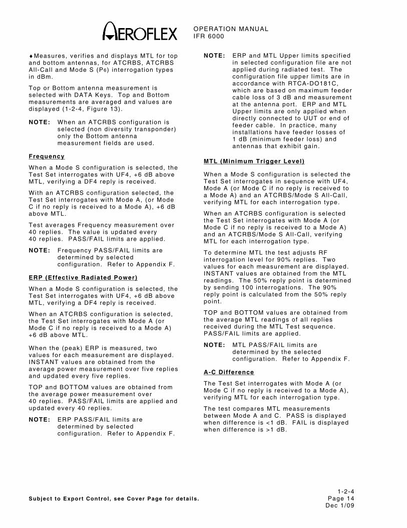
OPERATION MANUAL IFR 6000
1-2-4 Subject to Export Control , see Cover Page for deta i ls . Page 14
Dec 1/09
♦Measures, ver i f ies and d isp lays MTL for top and bot tom antennas, for ATCRBS, ATCRBS Al l -Cal l and Mode S (P6) in ter rogat ion types in dBm.
Top or Bot tom antenna measurement is se lected wi th DATA Keys. Top and Bot tom measurements are averaged and va lues are d isp layed (1-2-4, F igure 13) .
NOTE: When an ATCRBS conf igurat ion is se lected (non d ivers i ty t ransponder) on ly the Bot tom antenna measurement f ie lds are used.
Frequency
When a Mode S conf igurat ion is se lected, the Test Set in ter rogates wi th UF4, +6 dB above MTL, ver i fy ing a DF4 rep ly is rece ived.
Wi th an ATCRBS conf igurat ion se lected, the Test Set in ter rogates wi th Mode A, (or Mode C i f no rep ly is received to a Mode A) , +6 dB above MTL.
Test averages Frequency measurement over 40 rep l ies. The va lue is updated every 40 rep l ies. PASS/FAIL l imi ts are appl ied.
NOTE: Frequency PASS/FAIL l imi ts are determined by se lected conf igurat ion. Refer to Appendix F.
ERP (Effect ive Radiated Power)
When a Mode S conf igurat ion is se lected, the Test Set in ter rogates wi th UF4, +6 dB above MTL, ver i fy ing a DF4 rep ly is rece ived.
When an ATCRBS conf igurat ion is se lected, the Test Set in ter rogates wi th Mode A (or Mode C i f no rep ly is received to a Mode A) +6 dB above MTL.
When the (peak) ERP is measured, two va lues for each measurement are d isp layed. INSTANT values are obta ined f rom the average power measurement over f ive rep l ies and updated every f ive rep l ies.
TOP and BOTTOM values are obta ined f rom the average power measurement over 40 rep l ies. PASS/FAIL l imi ts are appl ied and updated every 40 rep l ies.
NOTE: ERP PASS/FAIL l imi ts are determined by se lected conf igurat ion. Refer to Appendix F.
NOTE: ERP and MTL Upper l imi ts spec i f ied in se lected conf igurat ion f i le are not appl ied dur ing rad iated test . The conf igurat ion f i le upper l imi ts are in accordance wi th RTCA-DO181C, which are based on maximum feeder cable loss of 3 dB and measurement at the antenna por t . ERP and MTL Upper l imi ts are on ly appl ied when d i rect ly connected to UUT or end of feeder cable. In pract ice, many insta l la t ions have feeder losses of 1 dB (min imum feeder loss) and antennas that exhib i t ga in .
MTL (Minimum Trigger Level)
When a Mode S conf igurat ion is se lected the Test Set in ter rogates in sequence wi th UF4, Mode A (or Mode C i f no rep ly is received to a Mode A) and an ATCRBS/Mode S Al l -Cal l , ver i fy ing MTL for each in ter rogat ion type.
When an ATCRBS conf igurat ion is se lected the Test Set in ter rogates wi th Mode A (or Mode C i f no rep ly is received to a Mode A) and an ATCRBS/Mode S Al l -Cal l , ver i fy ing MTL for each in ter rogat ion type.
To determine MTL the test ad justs RF in ter rogat ion leve l for 90% repl ies. Two va lues for each measurement are d isp layed. INSTANT values are obta ined f rom the MTL readings. The 50% reply po int is determined by sending 100 in ter rogat ions. The 90% reply po int is ca lcu la ted f rom the 50% reply po int .
TOP and BOTTOM values are obta ined f rom the average MTL readings of a l l rep l ies received dur ing the MTL Test sequence. PASS/FAIL l imi ts are appl ied.
NOTE: MTL PASS/FAIL l imi ts are determined by the se lected conf igurat ion. Refer to Appendix F.
A-C Difference
The Test Set in ter rogates wi th Mode A (or Mode C i f no rep ly is received to a Mode A) , ver i fy ing MTL for each in ter rogat ion type.
The test compares MTL measurements between Mode A and C. PASS is d isp layed when d i f ference is <1 dB. FAIL is d isp layed when d i f ference is >1 dB.
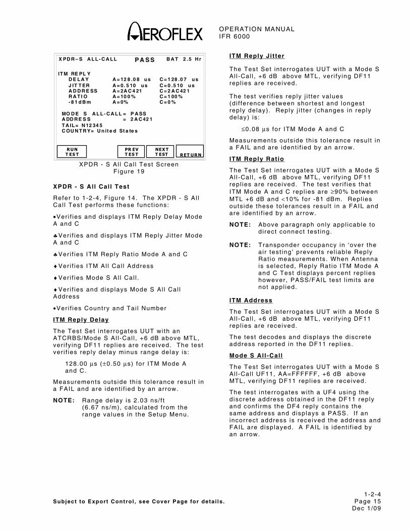
OPERATION MANUAL IFR 6000
1-2-4 Subject to Export Control , see Cover Page for deta i ls . Page 15
Dec 1/09
B A T 2 .5 H r
RUN T ES T
PR EV T ES T
X PD R – S A L L - C A L L
NEX T T EST
IT M RE PL Y D E L A Y A = 12 8 .0 8 u s C = 1 28 .0 7 u s J IT T ER A = 0. 5 10 u s C = 0 .5 10 u s A D D R E SS A = 2A C 4 21 C = 2 A C 42 1 R A T I O A = 10 0 % C = 1 00 % - 8 1 d B m A = 0% C = 0 % MO D E S A L L - C A L L = P A SS A DD R E S S = 2 A C 42 1 T A IL = N 12 34 5 C OU N T R Y= U n it e d St a te s
RET URN
P A S S
XPDR - S Al l Cal l Test Screen F igure 19
XPDR - S Al l Cal l Test
Refer to 1-2-4, F igure 14. The XPDR - S Al l Cal l Test per forms these funct ions:
•Ver i f ies and d isp lays ITM Reply Delay Mode A and C
♣Ver i f ies and d isp lays ITM Reply J i t ter Mode A and C
♣Ver i f ies ITM Reply Rat io Mode A and C
♦Ver i f ies ITM Al l Cal l Address
♦Ver i f ies Mode S Al l Cal l .
♦Ver i f ies and d isp lays Mode S Al l Cal l Address
•Ver i f ies Country and Tai l Number
ITM Reply Delay
The Test Set in ter rogates UUT wi th an ATCRBS/Mode S Al l -Cal l , +6 dB above MTL, ver i fy ing DF11 rep l ies are received. The test ver i f ies rep ly de lay minus range delay is :
128.00 μs (±0.50 μs) for ITM Mode A and C.
Measurements outs ide th is to lerance resul t in a FAIL and are ident i f ied by an arrow.
NOTE: Range delay is 2 .03 ns/ f t (6 .67 ns/m), ca lcu lated f rom the range va lues in the Setup Menu.
ITM Reply Ji t ter
The Test Set in ter rogates UUT wi th a Mode S Al l -Cal l , +6 dB above MTL, ver i fy ing DF11 rep l ies are received.
The test ver i f ies rep ly j i t ter va lues (d i f ference between shor test and longest rep ly de lay) . Reply j i t ter (changes in rep ly de lay) is :
≤0.08 μs for ITM Mode A and C
Measurements outs ide th is to lerance resul t in a FAIL and are ident i f ied by an arrow.
ITM Reply Ratio
The Test Set in ter rogates UUT wi th a Mode S Al l -Cal l , +6 dB above MTL, ver i fy ing DF11 rep l ies are received. The test ver i f ies that ITM Mode A and C rep l ies are ≥90% between MTL +6 dB and <10% for -81 dBm. Repl ies outs ide these to lerances resul t in a FAIL and are ident i f ied by an arrow.
NOTE: Above paragraph only appl icable to d i rect connect test ing.
NOTE: Transponder occupancy in ‘over the a i r test ing ’ prevents re l iab le Reply Rat io measurements. When Antenna is se lected, Reply Rat io ITM Mode A and C Test d isp lays percent rep l ies however , PASS/FAIL tes t l imi ts are not appl ied.
ITM Address
The Test Set in ter rogates UUT wi th a Mode S Al l -Cal l , +6 dB above MTL, ver i fy ing DF11 rep l ies are received.
The test decodes and d isp lays the d iscrete address repor ted in the DF11 rep l ies.
Mode S Al l -Cal l
The Test Set in ter rogates UUT wi th a Mode S Al l -Cal l UF11, AA=FFFFFF, +6 dB above MTL, ver i fy ing DF11 rep l ies are received.
The test in ter rogates wi th a UF4 us ing the d iscrete address obta ined in the DF11 rep ly and conf i rms the DF4 rep ly conta ins the same address and d isp lays a PASS. I f an incorrect address is rece ived the address and FAIL are d isp layed. A FAIL is ident i f ied by an arrow.
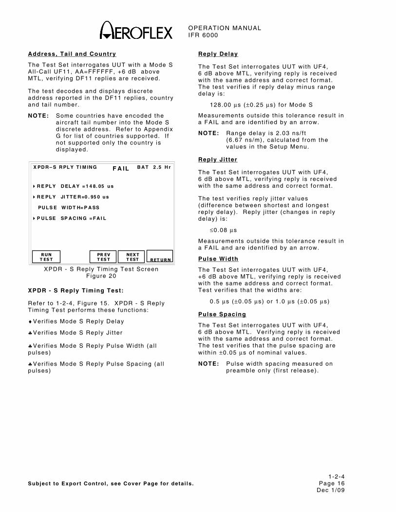
OPERATION MANUAL IFR 6000
1-2-4 Subject to Export Control , see Cover Page for deta i ls . Page 16
Dec 1/09
Address, Tai l and Country
The Test Set in ter rogates UUT wi th a Mode S Al l -Cal l UF11, AA=FFFFFF, +6 dB above MTL, ver i fy ing DF11 rep l ies are received.
The test decodes and d isp lays d iscrete address repor ted in the DF11 rep l ies, country and ta i l number.
NOTE: Some countr ies have encoded the a i rcraf t ta i l number in to the Mode S d iscrete address. Refer to Appendix G for l is t o f countr ies suppor ted. I f not suppor ted only the country is d isp layed.
B A T 2 .5 H r
R E PL Y D EL A Y = 1 4 8. 05 u s R E PL Y JI T T E R =0 . 95 0 u s PU L S E W ID T H= P A SS P U L SE SP A C IN G = F A I L
RUN T ES T PR EV
T ES T
X PD R – S R PL Y T I M IN G
NEX T T EST
RET URN
F A IL
XPDR - S Reply T iming Test Screen F igure 20
XPDR - S Reply Timing Test:
Refer to 1-2-4, F igure 15. XPDR - S Reply T iming Test per forms these funct ions:
♦Ver i f ies Mode S Reply Delay
♣Ver i f ies Mode S Reply J i t ter
♣Ver i f ies Mode S Reply Pulse Width (a l l pu lses)
♣Ver i f ies Mode S Reply Pulse Spacing (a l l pu lses)
Reply Delay
The Test Set in ter rogates UUT wi th UF4, 6 dB above MTL, ver i fy ing rep ly is rece ived wi th the same address and correct format . The test ver i f ies i f rep ly de lay minus range delay is :
128.00 μs (±0.25 μs) for Mode S
Measurements outs ide th is to lerance resul t in a FAIL and are ident i f ied by an arrow.
NOTE: Range delay is 2 .03 ns/ f t (6 .67 ns/m), ca lcu lated f rom the va lues in the Setup Menu.
Reply Ji t ter
The Test Set in ter rogates UUT wi th UF4, 6 dB above MTL, ver i fy ing rep ly is rece ived wi th the same address and correct format .
The test ver i f ies rep ly j i t ter va lues (d i f ference between shor test and longest rep ly de lay) . Reply j i t ter (changes in rep ly de lay) is :
≤0.08 μs
Measurements outs ide th is to lerance resul t in a FAIL and are ident i f ied by an arrow.
Pulse Width
The Test Set in ter rogates UUT wi th UF4, +6 dB above MTL, ver i fy ing rep ly is rece ived wi th the same address and correct format . Test ver i f ies that the widths are:
0 .5 μs (±0.05 μs) or 1 .0 μs (±0.05 μs)
Pulse Spacing
The Test Set in ter rogates UUT wi th UF4, 6 dB above MTL. Ver i fy ing rep ly is received wi th the same address and correct format . The test ver i f ies that the pu lse spac ing are wi th in ±0.05 μs of nominal va lues.
NOTE: Pulse width spac ing measured on preamble only ( f i rs t re lease) .
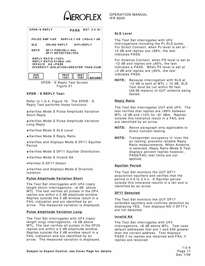
OPERATION MANUAL IFR 6000
1-2-4 Subject to Export Control , see Cover Page for deta i ls . Page 17
Dec 1/09
B A T 2 .5 H r
PU L S E A MP V A R SH R T = 0 .1 d B L N G= 0. 1 d B SL S ON = N O R EP L Y O F F = R EP L Y SQT R DF 11 P ER I OD = 1 .0 0 s DF 17 D E T EC T ED = YE S R EP L Y R A T I O = 1 0 0 % R EP L Y R A T I O 8 1 d B m = 0% IN V A L I D A A = P A SS D IV ER S IT Y IS OL A T I ON = GR E A T ER T H A N 2 5 d B
RUN T ES T PR EV
T ES T
X PD R – S R EP L Y
NEX T T EST
RET URN
PA SS
XPDR - S Reply Test Screen F igure 21
XPDR - S REPLY Test:
Refer to 1-2-4, F igure 16. The XPDR - S Reply Test per forms these funct ions:
♣Ver i f ies Mode S Pulse Ampl i tude Var ia t ion Shor t Reply
♣Ver i f ies Mode S Pulse Ampl i tude Var ia t ion Long Reply
♣Ver i f ies Mode S SLS Level
♣Ver i f ies Mode S Reply Rat io
♦Ver i f ies and d isp lays Mode S DF11 Squi t ter Per iod
♣Ver i f ies Mode S DF11 Squi t ter Dis t r ibut ion.
♦Ver i f ies Mode S Inval id AA
•Ver i f ies S DF17 Detect
♦Ver i f ies and d isp lays Mode S Divers i ty Iso la t ion
Pulse Ampli tude Variat ion Short
The Test Set in ter rogates wi th UF4 ( rep ly length shor t ) in ter rogat ions, +6 dB above MTL. The test ver i f ies a l l pu lses in the DF4 rep l ies are wi th in a 2 dB ampl i tude window. Repl ies outs ide the 2 dB window resul t in a FAIL ind icat ion and are ident i f ied by an arrow. The measured var ia t ion is d isp layed.
Pulse Ampli tude Variat ion Long
The Test Set in ter rogates wi th UF4 ( rep ly length long) in ter rogat ions, +6 dB above MTL. The test ver i f ies a l l pu lses in the DF20 rep l ies are wi th in a 2 dB ampl i tude window. Repl ies outs ide the 2 dB window resul t in a FAIL ind icat ion and are ident i f ied by an arrow. The measured var ia t ion is d isp layed.
SLS Level
The Test Set in ter rogates wi th UF4 in ter rogat ions inc lud ing the P5 SLS pulse. For Di rect Connect , when P5 leve l is set a t -12 dB and rep l ies are ≥99%, the test ind icates PASS.
For Antenna Connect , when PS level is set a t -12 dB and rep l ies are >90%, the test ind icates a PASS. When P5 level is set a t +3 dB and rep l ies are >90%, the test ind icates PASS.
NOTE: Because in ter rogat ion wi th SLS at -12 dB is sent a t MTL + 12 dB, SLS Test must be run wi th in 95 feet (28.96 meters) o f UUT antenna being tested.
Reply Ratio
The Test Set in ter rogates UUT wi th UF4. The test ver i f ies that rep l ies are ≥99% between MTL +6 dB and ≤10% for -81 dBm. Repl ies outs ide th is to lerance resul t in a FAIL and are ident i f ied by an arrow.
NOTE: Above paragraph only appl icable to d i rect connect test ing.
NOTE: Transponder occupancy in ‘over the a i r test ing ’ prevents re l iab le Reply Rat io measurements. When Antenna is se lected, Reply Rat io Mode S Test d isp lays percent rep l ies however , PASS/FAIL tes t l imi ts are not appl ied.
Squit ter Period
The Test Set moni tors the UUT DF11 acquis i t ion squi t ters and ver i f ies that the per iod is 0 .6 to 2.4 s . A Squi t ter per iod outs ide th is to lerance resul ts in a fa i l and is ident i f ied by an arrow.
DF17 Detected
The Test Set moni tors the UUT DF17 extended squi t ters and conf i rms detect ion by d isp lay ing YES. Test d isp lays NO i f DF17’s are not detected.
Inval id AA
The Test Set in ter rogates wi th UF4 in ter rogat ions, +6 dB above MTL. Test uses defaul t addresses that are 1 and 256 greater than the correct address. Test d isp lays PASS i f no rep l ies are received and FAIL i f rep l ies are received.
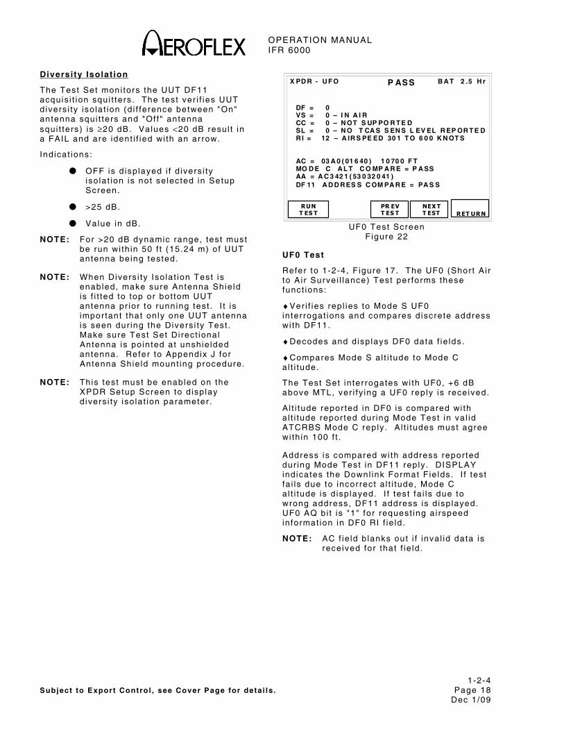
OPERATION MANUAL IFR 6000
1-2-4 Subject to Export Control , see Cover Page for deta i ls . Page 18
Dec 1/09
Diversi ty Isolat ion
The Test Set moni tors the UUT DF11 acquis i t ion squi t ters . The test ver i f ies UUT d ivers i ty iso la t ion (d i f ference between "On" antenna squi t ters and "Of f " antenna squi t ters) is ≥20 dB. Values <20 dB resul t in a FAIL and are ident i f ied wi th an arrow.
Ind icat ions:
● OFF is d isp layed i f d ivers i ty iso la t ion is not se lected in Setup Screen.
● >25 dB.
● Value in dB.
NOTE: For >20 dB dynamic range, test must be run wi th in 50 f t (15.24 m) of UUT antenna being tested.
NOTE: When Divers i ty Iso la t ion Test is enabled, make sure Antenna Shie ld is f i t ted to top or bot tom UUT antenna pr ior to running test . I t is impor tant that on ly one UUT antenna is seen dur ing the Divers i ty Test . Make sure Test Set Di rect ional Antenna is po inted at unshie lded antenna. Refer to Appendix J for Antenna Shie ld mount ing procedure.
NOTE: This test must be enabled on the XPDR Setup Screen to d isp lay d ivers i ty iso la t ion parameter .
B A T 2 .5 H r
DF = 0 VS = 0 – I N A I R CC = 0 – N OT S UP PO R T E D SL = 0 – N O T CA S S EN S L EV EL R EP OR T E D R I = 12 – A IR S PE ED 30 1 T O 6 0 0 K N OT S AC = 03 A 0 ( 01 6 40 ) 1 0 70 0 F T MO D E C A L T C O MP A R E = P A SS AA = A C 3 42 1 ( 53 0 32 0 41 ) DF 11 A D D R ES S C OM PA R E = PA S S
RUNT ES T PR EV
T ES T
X PD R - U F O
NEX T T EST
RET URN
P ASS
UF0 Test Screen F igure 22
UF0 Test
Refer to 1-2-4, F igure 17. The UF0 (Shor t A i r to A i r Surve i l lance) Test per forms these funct ions:
♦Ver i f ies rep l ies to Mode S UF0 in ter rogat ions and compares d iscrete address wi th DF11.
♦Decodes and d isp lays DF0 data f ie lds.
♦Compares Mode S a l t i tude to Mode C a l t i tude.
The Test Set in ter rogates wi th UF0, +6 dB above MTL, ver i fy ing a UF0 rep ly is rece ived.
A l t i tude repor ted in DF0 is compared wi th a l t i tude repor ted dur ing Mode Test in va l id ATCRBS Mode C reply . A l t i tudes must agree wi th in 100 f t .
Address is compared wi th address repor ted dur ing Mode Test in DF11 reply . DISPLAY ind icates the Downl ink Format F ie lds. I f test fa i ls due to incorrect a l t i tude, Mode C a l t i tude is d isp layed. I f test fa i ls due to wrong address, DF11 address is d isp layed. UF0 AQ bi t is "1" for request ing a i rspeed in format ion in DF0 RI f ie ld .
NOTE: AC f ie ld b lanks out i f inva l id data is received for that f ie ld .

OPERATION MANUAL IFR 6000
1-2-4 Subject to Export Control , see Cover Page for deta i ls . Page 19
Dec 1/09
Testing VS (Vert ical Status)
ICAO amendment 77 t ransponders on ly rep l ies to Mode S d iscrete in ter rogat ions when insta l la t ion is in ground s tate. Refer to para 1-2-4.3.2 for UUT ADDRESS and MANUAL AA set t ings.
B A T 2 .5 H r
DF = 4 F S = 3 - AL ER T N O S P I O N G R OU N D DR = 0 – N O D O WN L IN K R EQ U ES T UM = 0 - ( ID S = 0 ) ( I IS = 0) AC = 03 A 0 ( 01 6 40 ) 1 0 70 0 F T MO D E C A L T C O MP A R E = P A SS AA = A C 3 42 1 ( 53 0 32 0 41 ) DF 11 A D D R ES S C OM PA R E = PA S S
RUN T ES T PR EV
T ES T
X PD R – UF 4
NEX T T EST
RET URN
P ASS
UF4 Test Screen F igure 23
UF4 Test
Refer to 1-2-4, F igure 18. UF4 (Shor t Surve i l lance Al t i tude) Test per forms these funct ions:
♦Ver i f ies rep l ies to Mode S UF4 in ter rogat ions and compares d iscrete address wi th DF11.
♦Decodes and d isp lays DF4 data f ie lds.
♦Compares Mode S a l t i tude to Mode C a l t i tude.
The Test Set in ter rogates wi th UF4, +6 dB above MTL, ver i fy ing a DF4 rep ly is rece ived.
A l t i tude repor ted in DF4 is compared wi th a l t i tude repor ted dur ing Mode Test in va l id ATCRBS Mode C reply . A l t i tudes must agree wi th in 100 f t .
Address is compared wi th address repor ted dur ing Mode Test .
NOTE: AC f ie ld b lanks out i f inva l id data is received for that f ie ld .
Test ing FS (Fl ight Status)
ICAO amendment 77 t ransponders on ly rep ly to Mode S d iscrete in ter rogat ions when insta l la t ion is in ground s tate. Refer to para 1-2-4.3.2 for UUT ADDRESS and MANUAL AA set t ings.
B A T 2 .5 H r
DF =5 F S= 0- NO A L E R T N O S PI I N A I R DR = 0 - N O D OW N L IN K R EQ UE ST UM = 0 - ( ID S = 0 ) ( I IS = 0) ID = 02 0 A ( 01 0 12 ) O C T A L ID 2 6 00 MO D E A ID C O M PA R E = PA S S AA = A C 3 42 1 ( 53 0 32 0 41 ) DF 11 A D D R ES S C OM PA R E = PA S S
RUNT ES T PR EV
T ES T
X PD R – U F 5
NEX TT EST
RET URN
P ASS
UF5 Test Screen F igure 24
UF5 Test
Refer to 1-2-4, F igure 19. The UF5 Test (Shor t Surve i l lance Ident i ty ) per forms these funct ions:
♦Ver i f ies rep l ies to Mode S UF5 in ter rogat ions and compares d iscrete address wi th DF11.
♦Decodes and d isp lays DF5 data f ie lds.
♦Compares Mode S Ident i ty Code to Mode A Squawk Code.
The Test Set in ter rogates wi th UF5, +6 dB above MTL, ver i fy ing a DF5 rep ly is rece ived.
ID code repor ted in DF5 is compared wi th ID code repor ted dur ing Mode Test in va l id ATCRBS Mode A reply . Address is compared wi th address repor ted dur ing Mode Test .

OPERATION MANUAL IFR 6000
1-2-4 Subject to Export Control , see Cover Page for deta i ls . Page 20
Dec 1/09
Testing FS (Fl ight Status)
ICAO amendment 77 t ransponders on ly rep ly to Mode S d iscrete in ter rogat ions when insta l la t ion is in ground s tate. Refer to para 1-2-4.3.2 for UUT ADDRESS and MANUAL AA set t ings.
B A T 2 .5 H r
DF =1 1 C A= 0 - L E VEL 2 C A M OD E PI = 0 2F 0 8 D AA = A C 3 42 1 ( 53 0 32 0 41 ) I I L OC K O U T T IM ER = 1 8S I I M A T C H = P A SS SI L OC K O U T T IM ER = 1 8 S SI M A T C H = PA S S
RUN T ES T PR EV
T ES T
X PD R – U F 11
NEX T T EST
RET URN
P ASS
UF11 Test Screen F igure 25
UF11 Test
Refer to 1-2-4, F igure 20. UF11 Test per forms these funct ions:
♦ In ter rogates wi th Mode S UF11, AP set FFFFFF. Decodes and d isp lays DF11 rep l ies.
♣Performs comprehensive I I and SI Match Test .
•Performs I I and SI lockout T imer Test .
The Test Set in ter rogates wi th UF11, +6 dB above MTL, ver i fy ing a DF11 rep ly is received.
Address is compared wi th address repor ted dur ing Mode Test in DF11 rep ly (1-2-4, F igure 20) . Test in ter rogates wi th a UF11, us ing the 15 I I codes, in sequence f rom 1 to 15. I f a l l codes are correct PASS is d isp layed. I f the t ransponder suppor ts SI (Survei l lance Ident i f ier ) each of the 63 SI codes f rom 1 to 63 are tested. When a l l codes are correct PASS is d isp layed. BDS 1,0 is ver i f ied to determine SI suppor t .
NOTE: When a s ing le code fa i ls the code is d isp layed. When more than one code fa i ls , the range of codes are d isp layed. An arrow ident i f ies a FAIL (1-2-4, F igure 21) .
The mul t i -s i te lockout protocol is u t i l ized in conjunct ion wi th an I I code to ver i fy lockout (not accept any Mode S only Al l -Cal l ) t ime. I f lockout t ime is 18 sec (±1 sec) , PASS is d isp layed. FAIL is d isp layed i f lockout t ime is outs ide th is window.
The mul t i -s i te lockout protocol is u t i l ized in conjunct ion wi th an SI code to ver i fy lockout (not accept any Mode S only Al l -Cal l ) t ime. I f lockout t ime is 18 sec (±1 sec) , PASS is d isp layed. FAIL is d isp layed i f lockout t ime is outs ide th is window.
The test in ter rogates dur ing the lockout per iod wi th a d i f ferent SI code to conf i rm in ter rogat ion acceptance.
NOTE: Due to long test t ime requi red, lockout t imer test is not run as par t o f Auto Test . Test is run only i f UF11 Test is per formed separate ly .
B A T 2 .5 H r
DF = 1 1 C A = 0 - L EV EL 2 C A M OD E PI = 02 F 0 8 D AA = A C 3 42 1 ( 53 0 32 0 41 ) I I L OC K O U T T IM ER = 1 8S
I I M AT C H = 0 - 1 ,3 - 4, 6- 7 , 9- 1 0, 1 2- 1 3 ,1 5 SI L OC K O U T T IM ER = 1 8 S S I M A T C H = 1 -2 , 4- 5 ,7 - 8 ,1 0- 1 1 ,1 3 -1 4 , 1 6 -1 7 ,1 9 - 20 ,2 2 - 23 , 25 - 26 , 2 8 -2 9 ,3 1 - 32 ,3 4 - 35 , 37 - 38 , 4 0 -4 1 ,4 3 - 44 ,4 6 - 47 , 49 - 50 , 5 2 -5 3 ,5 5 - 56 ,5 8 - 59 , 61 - 62
RUNT ES T
MOREI NFO
PR EV T ES T
X PD R – UF 11
NEX T T EST
RET URN
F AIL
UF11 FAIL Test Screen F igure 26

OPERATION MANUAL IFR 6000
1-2-4 Subject to Export Control , see Cover Page for deta i ls . Page 21
Dec 1/09
B A T 2 .5 H r
DF =1 6 VS =0 – IN A IR SL = 0 R I = 0 – NO O N – B O A R D T C A S MV = 30 0 10 0 00 0 00 0 00 AC = 0 3 A0 ( 0 16 4 0) 10 7 00 f t MO D E C A L T C O MP A R E= P A SS AA = A C 3 42 1 ( 53 0 32 0 41 ) DF 11 A D D R ES S C OM PA R E = PA S S
RUN T ES T PR EV
T ES T
X PD R – U F 16
NEX T T EST
RET URN
P ASS
UF16 Test Screen F igure 27
UF16 Test
Refer to 1-2-4, F igure 22. UF16 Test (Long Ai r to Ai r Survei l lance) per forms these funct ions:
♦Ver i f ies rep l ies to Mode S UF16 in ter rogat ions and compares d iscrete address wi th DF11.
♦Decodes and d isp lays DF16 data f ie lds.
♦Compares Mode S Al t i tude to Mode C Al t i tude.
The Test Set in ter rogates wi th UF16, +6 dB above MTL, ver i fy ing a DF16 rep ly is received.
A l t i tude repor ted in DF16 is compared wi th a l t i tude repor ted dur ing Mode Test in va l id ATCRBS Mode C reply . A l t i tudes must agree wi th in 100 f t .
Address is compared wi th address repor ted dur ing Mode Test in DF11 rep ly . The DISPLAY ind icates the Downl ink Format F ie lds. I f test fa i ls because of incorrect a l t i tude, Mode C a l t i tude is d isp layed. I f test fa i ls due to wrong address, DF11 address is d isp layed.
NOTE: AC f ie ld b lanks out i f inva l id data is received for that f ie ld .
NOTE: No reply to UF16 resul ts in Mode S pass in Auto Test .
NOTE: Repl ies to UF16 are received only i f an act ive TCAS I I system is insta l led.
Testing VS (Vert ical Status)
ICAO amendment 77 t ransponders on ly rep l ies to Mode S d iscrete in ter rogat ions when insta l la t ion is in ground s tate. Refer to para 1-2-4.3.2 for UUT ADDRESS and MANUAL AA set t ings.
B A T 2 . 5 H r
D F = 2 0F S = 3 - A L E R T N O S P I O N G R O U N DD R = 0 - N O D O W N L I N K R E Q U E S TU M = 0 ( I D S = 0 ) ( I I S = 0 )M B = 3 0 0 1 0 0 0 0 0 0 0 0 0 0
A C = 0 3 A0 ( 0 1 6 4 0 ) 1 0 7 0 0 f tM O D E C A L T C O M P A R E = P A S SA A = A C 3 4 2 1 ( 5 3 0 3 2 0 4 1 )D F 1 1 A D D R E S S C O M P A R E = P A S S
R U NT E S T
P R E VT E S T
X P D R – U F 2 0
N E X TT E S T R E T U R N
PASS
F20 Test Screen F igure 28
UF20 Test
Refer to 1-2-4, F igure 23. UF20 (Long Survei l lance Al t i tude) Test per forms these funct ions:
♦Ver i f ies rep l ies to Mode S UF20 in ter rogat ions and compares d iscrete address wi th DF11.
♦Decodes and d isp lays DF20 data f ie lds. Disp lays MB message f ie ld in HEX.
♦Compares Mode S a l t i tude to Mode C a l t i tude.
The Test Set in ter rogates wi th UF20 (Comm A, a l t i tude request) , RR=17 ( long rep ly) , DI=7, RRS=0, request ing a BDS 1,0 data l ink capabi l i ty repor t , +6 dB above MTL, ver i fy ing a DF20 rep ly is rece ived. I f rep ly is not received, the test in ter rogates for BDS 3,0 TCAS sensi t iv i ty s ta tus message.
A l t i tude repor ted in DF20 is compared wi th a l t i tude repor ted dur ing Mode Test in va l id ATCRBS Mode C reply . A l t i tudes must agree wi th in 100 f t .
Address is compared wi th address repor ted dur ing Mode Test in DF11 rep ly .

OPERATION MANUAL IFR 6000
1-2-4 Subject to Export Control , see Cover Page for deta i ls . Page 22
Dec 1/09
NOTE: The BDS 3,0 TCAS sensi t iv i ty s ta tus message in ter rogates wi th Mode S UF20 (Comm A, a l t i tude request) , RR=19 ( long rep ly) , DI=7, RRS=0, MA=05000000000000, ver i fy ing DF20 rep ly received has correct a l t i tude (compared wi th Mode C a l t i tude) , address (compared wi th Mode Test address) and format .
NOTE: Data d isp layed in MB message f ie ld is not decoded.
NOTE: The Data l ink Capabi l i ty Repor t determines the leve l o f t ransponder under test .
NOTE: AC f ie ld b lanks out i f inva l id data is received for that f ie ld .
NOTE: Transponders wi thout act ive subsystems capable of accept ing Comm A data do not rep ly to UF20 in ter rogat ions.
Testing FS (Fl ight Status )
ICAO amendment 77 t ransponders on ly rep ly to Mode S d iscrete in ter rogat ions when insta l la t ion is in ground s tate. Refer to para 1-2-4.3.2 for UUT ADDRESS and MANUAL AA set t ings.
B A T 2 .5 H r
DF =2 1 F S= 3- AL ER T N O S PI O N GR O U N D DR = 0 - N O D OW N L I N K R EQU ES T UM = 0 ( ID S =0 ) ( I IS = 0 ) MB = 3 00 1 00 0 00 0 00 0 0 ID = 03 A 0 ( 01 6 40 ) O C T A L ID 6 1 40 MO D E A ID C OM P A R E= P A SS AA = A C 3 42 1 ( 53 0 32 0 41 ) DF 11 A D D R ES S C OM PA R E = PA S S
RUNT ES T PR EV
T ES T
X PD R – U F 21
NEX T T EST
RET URN
P ASS
UF21 Test Screen PASS Figure 29
UF21 Test
Refer to 1-2-4, F igure 24. UF21 (Long Survei l lance Ident i ty ) Test per forms these funct ions:
♦Ver i f ies rep l ies to Mode S UF21 in ter rogat ions and compares d iscrete address wi th DF11.
♦Decodes and d isp lays DF21 data f ie lds. Disp lays MB message f ie ld in HEX.
♦Compares Mode S Ident i ty Code to Mode A Squawk Code.
The Test Set in ter rogates wi th UF21 (Comm A, a l t i tude request) , RR=17 ( long rep ly) , DI=7, RRS=0, request ing a BDS 1,0 data l ink capabi l i ty repor t , +6 dB above MTL, ver i fy ing a DF21 rep ly is rece ived. I f rep ly is not received test in ter rogates for BDS 3,0 TCAS sensi t iv i ty s ta tus message.
ID code repor ted in DF21 is compared wi th ID code repor ted dur ing Mode Test in va l id ATCRBS Mode A reply .
Address is compared wi th address repor ted dur ing Mode Test in DF11 rep ly .
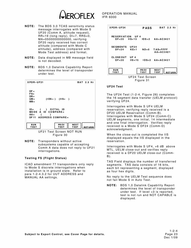
OPERATION MANUAL IFR 6000
1-2-4 Subject to Export Control , see Cover Page for deta i ls . Page 23
Dec 1/09
NOTE: The BDS 3,0 TCAS sensi t iv i ty s ta tus message in ter rogates wi th Mode S UF20 (Comm A, a l t i tude request) , RR=19 ( long rep ly) , DI=7, RRS=0, MA=05000000000000, ver i fy ing DF20 rep ly received has correct a l t i tude (compared wi th Mode C a l t i tude) , address (compared wi th Mode Test address) and format .
NOTE: Data d isp layed in MB message f ie ld is not decoded.
NOTE: BDS 1,0 Data l ink Capabi l i ty Repor t determines the leve l o f t ransponder under test .
B A T 2 .5 H r
DF = F S= DR = UM = ( I DS = ) ( I I S= ) MB = ID = ( ) O C T A L ID MO D E A ID C O M PA R E = AA = ( ) DF 11 A D D R ES S C OM PA R E =
RUN T ES T PR EV
T ES T
X PD R – U F 21
NEX T T EST
RET URN
UF21 Test Screen NOT RUN Figure 30
NOTE: Transponders wi thout act ive subsystems capable of accept ing Comm A data does not rep ly to UF21 in ter rogat ions.
Testing FS (Fl ight Status)
ICAO amendment 77 t ransponders on ly rep ly to Mode S d iscrete in ter rogat ions when insta l la t ion is in ground s tate. Refer to para 1-2-4.3.2 for UUT ADDRESS and MANUAL AA set t ings.
B A T 2 .5 H r
RE S ER V AT ION U F 4 D F = 2 0 I I S= 1 5 ID S = 2 A A = A C 34 2 1 SE GM EN T S U F 2 4 D F = 2 4 K E= 1 N D = 0 T A S= F F F F A A = A C 3 42 1 CL OSE OU T U F 4 D F = 2 0 I IS = 15 I D S= 2 A A = A C 34 2 1
RUNT ES T PR EV
T ES T
X PD R – U F 24
NEX TT EST
RET URN
P ASS
UF24 Test Screen F igure 31
UF24 Test
The UF24 Test (1-2-4, F igure 26) completes the 16 segment data t ransfer (UELM protocol ) ver i fy ing UF24.
In ter rogates wi th Mode S UF4 UELM reservat ion, ver i fy ing rep ly received is a DF20 UELM Reservat ion (Comm-B). In ter rogates wi th Mode S UF24 (Comm-C) UELM segments, one in i t ia l , 14 in termediate and one f ina l in ter rogat ion. Ver i f ies rep ly received is a Mode S DF24 (Comm-D) acknowledgment .
When the c lose-out is completed the I IS d isp layed equals the I IS d isp layed in the reservat ion.
In ter rogates wi th Mode S UF4, +6 dB above MTL, UELM c lose-out and ver i f ies rep ly received is a DF20 UELM c lose-out (Comm-B).
TAS Fie ld d isp lays the number of t ransferred segments. TAS data consis ts o f 16 b i ts , each b i t represent ing a segment , d isp layed as four hex d ig i ts .
No rep ly to the UELM Test sequence does not fa i l Mode S in Auto Test .
NOTE: BDS 1,0 Data l ink Capabi l i ty Repor t determines the leve l o f t ransponder under test . I f leve l <3 is repor ted, test is not run and NOT CAPABLE is d isp layed.
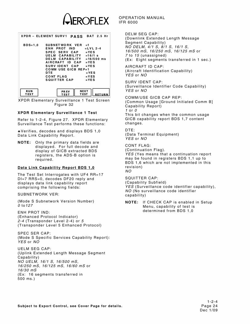
OPERATION MANUAL IFR 6000
1-2-4 Subject to Export Control , see Cover Page for deta i ls . Page 24
Dec 1/09
B A T 2 .5 H r
RUN T ES T
PR EV T ES T
X PD R – EL E M EN T SU R V 1
NEX T T EST
B D S= 1 ,0 SU B N ET WO R K VE R =1 E N H PR OT IN D = L V L 2 - 4 S PE C SE R V C A P = YE S U E L M C A PA B IL IT Y =1 6 /1 s D E L M C A PA B IL IT Y = 16 /5 0 0 ms A I R C RA F T ID C A P = YE S S U R V ID E N T C A P = YE S C O MM U SE G IC B RE P= 1 D T E = YE S C O NT F L A G = Y ES S QU IT T ER C A P = YE S
RET URN
P A SS
XPDR Elementary Survei l lance 1 Test Screen F igure 32
XPDR Elementary Survei l lance 1 Test
Refer to 1-2-4, F igure 27. XPDR Elementary Surve i l lance Test per forms these funct ions:
♣Ver i f ies , decodes and d isp lays BDS 1,0 Data L ink Capabi l i ty Repor t .
NOTE: Only the pr imary data f ie lds are d isp layed. For fu l l decode and d isp lay of GICB ext racted BDS regis ters , the ADS-B opt ion is requi red.
Data Link Capabi l i ty Report BDS 1,0
The Test Set In ter rogates wi th UF4 RR=17 DI=7 RRS=0, decodes DF20 rep ly and d isp lays data l ink capabi l i ty repor t compr is ing the fo l lowing f ie lds:
SUBNETWORK VER:
(Mode S Subnetwork Vers ion Number) 0 to127
ENH PROT IND: (Enhanced Protocol Ind icator) 2-4 (Transponder Level 2-4) or 5 (Transponder Level 5 Enhanced Protocol )
SPEC SER CAP: (Mode S Speci f ic Serv ices Capabi l i ty Repor t ) : YES or NO
UELM SEG CAP: (Upl ink Extended Length Message Segment Capabi l i ty ) NO UELM , 16/1 S , 16/500 mS , 16/250 mS , 16/125 mS , 16/60 mS or 16/30 mS (Ex: 16 segments t ransferred in 500 ms.)
DELM SEG CAP: (Downl ink Extended Length Message Segment Capabi l i ty ) NO DELM , 4/1 S , 8/1 S , 16/1 S , 16/500 mS , 16/250 mS , 16/125 mS or 7 to 15 (unass igned) (Ex: E ight segments t ransferred in 1 sec. )
AIRCRAFT ID CAP: (A i rcraf t Ident i f icat ion Capabi l i ty ) YES or NO
SURV IDENT CAP: (Surve i l lance Ident i f ier Code Capabi l i ty ) YES or NO
COMM/USE GICB CAP REP: (Common Usage [Ground In i t ia ted Comm B] Capabi l i ty Repor t ) 1 or 0 This b i t changes when the common usage GICB capabi l i ty repor t BDS 1,7 content changes.
DTE: (Data Terminal Equipment) YES or NO
CONT FLAG: (Cont inuat ion F lag) . YES (Yes means that a cont inuat ion repor t may be found in reg is ters BDS 1,1 up to BDS 1,6 which are not implemented in th is rev is ion) NO
SQUITTER CAP: (Capabi l i ty Subf ie ld) YES (Surve i l lance code ident i f ier capabi l i ty ) , NO (No surve i l lance code ident i f ier capabi l i ty )
NOTE: I f CHECK CAP is enabled in Setup Menu, capabi l i ty o f test is determined f rom BDS 1,0

OPERATION MANUAL IFR 6000
1-2-4 Subject to Export Control , see Cover Page for deta i ls . Page 25
Dec 1/09
B A T 2 .5 H r
RUN T ES T
PR EV T ES T
X PD R – EL E M EN T SU R V 2
NEX T T EST
B D S = 1 , 7 : 0 , 5 : 0 , 6 : 0 , 7 : 0 , 8 : 0 , 9 : 0 , A : 2 , 0 : 2 , 1 : 4 , 0 : 4 , 1 : 4 , 2 : 4 , 3 : 4 , 4 : 4 , 5 : 4 , 8 : 5 , 0 : 5 , 1 : 5 , 2 : 5 , 3 : 5 , 4 : 5 , 5 : 5 , 6 : 5 , F : 6 , 0 B D S 1 , 8 = 0 0 0 0 0 0 0 0 0 0 0 0 0 0 B D S 1 , 9 = 0 0 0 0 0 0 0 0 0 0 0 0 0 0 B D S 1 , A = 0 0 0 0 0 0 0 0 0 0 0 0 0 0 B D S 1 , B = 0 0 0 0 0 0 0 0 0 0 0 0 0 0 B D S 1 , C = 0 0 0 0 0 0 0 0 0 0 0 0 0 0 B D S= 2 ,0 F L IG HT ID = U A 6 61 B D S= 3 ,0 A RA =1 1 10 1 01 0 00 0 00 0 R A C = 10 1 0 R A T = 0
RET URN
P A SS
XPDR Elementary Survei l lance 2 Test Screen F igure 33
XPDR Elementary Survei l lance 2 Test
Refer to 1-2-4, F igure 28. XPDR Elementary Surve i l lance Test per forms these funct ions:
♣Ver i f ies , decodes and d isp lays BDS 1,7 Common Usage GICB Capabi l i ty Repor t .
♣Ver i f ies , decodes and d isp lays BDS 1,8 to BDS 1,C Speci f ic Serv ices Capabi l i ty Repor t .
♣Ver i f ies , decodes and d isp lays BDS 2,0 Ai rcraf t Ident i f icat ion (F l ight ID) .
♣Ver i f ies , decodes and d isp lays BDS 3,0 ACAS Resolut ion Adv isory .
NOTE: Only pr imary data f ie lds are d isp layed. For fu l l decode and d isp lay of GICB ext racted BDS regis ters , the ADS-B opt ion is requi red.
GICB Common Usage Capabi l i t ies Repor t :
In ter rogates wi th UF4 RR=16 DI=7 RRS=7, decodes DF20 rep ly and d isp lays common usage GICB capabi l i ty repor t .
The Screen d isp lays BDS Numbers for the common usage GICB serv ices current ly suppor ted by the t ransponder and decodable by the Test Set .
BDS DESCRIPTION
0.5 Ext Squit ter Airborne Posit ion
0,6 Ext Squit ter Surface Posit ion
0,7 Ext Squit ter Status
0,8 Ext Squit ter Type and Ident i f icat ion
0,9 Ext Squit ter Airborne Veloci ty Information
0,A Ext Squit ter Event Driven Information
1,0 Data Link Capabi l i ty Report
1,7 Common Usage GICB Capabi l i ty Report
2,0 Aircraft Ident i f icat ion (Fl ight ID)
2,1 Aircraft Registrat ion Number
3.0 ACAS Resolut ion Advisory
4,0 Aircraft Vert ical Intent ion
4,1 Next Way Point Ident i f ier
4,2 Next Way Point Posi t ion
4,3 Next Way Point Information
4,4 Meteorological Rout ine Report
4,5 Meteorological Hazard Report
4,8 VHF Channel Report
5,0 Track and Turn Report
5,1 Posit ion Coarse
5,2 Posit ion Fine
5,3 Air Referenced State Vector
5,4 Way Point 1
5,5 Way Point 2
5,6 Way Point 3
5,F Quasi-Stat ic Parameter Monitor ing
6,0 Heading and Speed Report
Common Usage GICB BDS Table 2
NOTE: Refer to 1-2-4, Table 2. Dark Shaded BDS are not suppor ted by current IFR 6000 sof tware. L ight shaded BDS are suppor ted by ADS-B opt ion.
Specif ic Services GICB Capabi l i ty Report BDS 1,8
BDS 1,8 In ter rogates wi th UF4 RR=17 DI=7 and RRS=8. DF20 reply BDS regis ter content d isp layed as 14 HEX d ig i ts . Each b i t set ind icates capabi l i ty suppor ted for BDS 0,1 to 3,8.
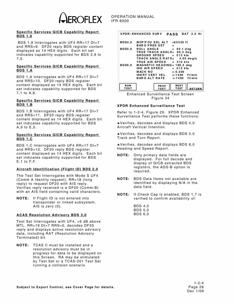
OPERATION MANUAL IFR 6000
1-2-4 Subject to Export Control , see Cover Page for deta i ls . Page 26
Dec 1/09
Specif ic Services GICB Capabi l i ty Report BDS 1,9
BDS 1,9 In ter rogates wi th UF4 RR=17 DI=7 and RRS=9. DF20 reply BDS regis ter content d isp layed as 14 HEX d ig i ts . Each b i t set ind icates capabi l i ty suppor ted for BDS 3,9 to 7,0.
Specif ic Services GICB Capabi l i ty Report BDS 1,A
BDS 1,A In terrogates wi th UF4 RR=17 DI=7 and RRS=10. DF20 reply BDS regis ter content d isp layed as 14 HEX d ig i ts . Each b i t set ind icates capabi l i ty suppor ted for BDS 7,1 to A,8.
Specif ic Services GICB Capabi l i ty Report BDS 1,B
BDS 1,B In terrogates wi th UF4 RR=17 DI=7 and RRS=11. DF20 reply BDS regis ter content d isp layed as 14 HEX d ig i ts . Each b i t set ind icates capabi l i ty suppor ted for BDS A,9 to E,0.
Specif ic Services GICB Capabi l i ty Report BDS 1,C
BDS 1,C Interrogates wi th UF4 RR=17 DI=7 and RRS=12. DF20 reply BDS regis ter content d isp layed as 14 HEX d ig i ts . Each b i t set ind icates capabi l i ty suppor ted for BDS E,1 to F,F.
Aircraft Identi f icat ion (Fl ight ID) BDS 2,0
The Test Set In ter rogates wi th Mode S UF4 (Comm A Ident i ty request) , RR=18 ( long reply) to request DF20 wi th AIS reply . Ver i f ies rep ly received is a DF20 (Comm-B) wi th an AIS f ie ld conta in ing va l id characters .
NOTE: I f Fl ight ID is not entered in to t ransponder or l inked subsystem, AIS is zero (0) .
ACAS Resolut ion Advisory BDS 3,0
Test Set In ter rogates wi th UF4, +6 dB above MTL, RR=19 DI=7 RRS=0, decodes DF20 rep ly and d isp lays act ive reso lut ion adv isory data, inc lud ing RAT (Resolut ion Advisory Terminated) b i t .
NOTE: TCAS I I must be insta l led and a resolut ion adv isory must be in progress for data to be d isp layed on th is Screen. RA may be s t imulated by Test Set or a TCAS-201 Test Set running a co l l is ion scenar io
B A T 2 .5 H r
RUNT ES T
PR EV T ES T
X PD R – EN H A N C ED S UR V
NEX T T EST
B D S4 ,0 M CP /F CU S EL AL T =6 5 5 20 f t B AR O P R ES S ET = B D S5 ,0 R OL L A N GL E = 4 0 .1 d eg T R U E T R A C K A N GL E= 9 0. 3 d e g GR OU N D SP EE D = 5 1 2 k ts T R A C K A N GL E R AT E= 4. 0 0 d e g /s T R U E A IR SP EE D = 5 12 k t s B D S6 ,0 M AG N ET I C H E A D IN G = 1 80 .3 d eg IN D AI R S P EE D = 5 1 2 k ts M AC H N O = 0 .3 00 IN E R T V ER T VE L =- 1 4 00 f t / min B AR O A L T R A T E =- 1 4 00 f t / min
RET URN
P A SS
Enhanced Surve i l lance Test Screen F igure 34
XPDR Enhanced Survei l lance Test
Refer to 1-2-4, F igure 29. XPDR Enhanced Surve i l lance Test per forms these funct ions:
♣Ver i f ies , decodes and d isp lays BDS 4,0 Ai rcraf t Ver t ica l In tent ion.
♣Ver i f ies , decodes and d isp lays BDS 5.0 Track and Turn Repor t .
♣Ver i f ies , decodes and d isp lays BDS 6,0 Heading and Speed Repor t .
NOTE: Only pr imary data f ie lds are d isp layed. For fu l l decode and d isp lay of GICB ext racted BDS regis ters , the ADS-B opt ion is requi red.
NOTE: BDS Data I tems not avai lab le are ident i f ied by d isp lay ing N/A in the data f ie ld .
NOTE: I f Check Cap is enabled, BDS 1,7 is ver i f ied to conf i rm avai lab i l i ty o f :
BDS 4,0 BDS 5,0 BDS 6,0

OPERATION MANUAL IFR 6000
1-2-4 Subject to Export Control , see Cover Page for deta i ls . Page 27
Dec 1/09
Aircraft Vert ical Intention BDS 4,0
The Test Set In ter rogates wi th UF4 RR=20 DI=7 RRS=0, decodes DF20 rep ly and d isp lays ver t ica l in tent repor t data.
NOTE: ADLP (Ai r Data L ink Processor) must be insta l led or t ransponder must have embedded ADLP to receive data f rom subsystem ( in th is case the FMS [F l ight Management System]) .
MCP/FCU SEL ALT:
(Mode Contro l Panel /F l ight Contro l Uni t Selected Al t i tude) d isp layed in feet .
Track and Turn Report BDS 5,0
The Test Set In ter rogates wi th UF4 RR=21 DI=7 RRS=0, decodes DF20 rep ly and d isp lays Track and Turn Repor t data.
NOTE: ADLP (Ai r Data L ink Processor) must be insta l led or t ransponder must have embedded ADLP to receive data f rom subsystem ( in th is case the FMS [F l ight Management System]) .
ROLL ANGLE:
±90.0 deg
TRUE TRACK ANGLE:
(True Track Angle) 0 to 359 deg
GROUND SPEED:
(Ground Speed) 0 to 2048 k ts (2 k t reso lut ion)
TRUE TRACK ANGLE RATE:
(True Track Angle Rate) ±16.0 deg/sec
TRUE AIR SPEED:
(True Ai r Speed) 0 to 2046 k ts (2 k t reso lut ion)
Heading and Speed Report BDS 6, 0
The Test Set In ter rogates wi th UF4 RR=22 DI=7 RRS=0, decodes DF20 rep ly and d isp lays Heading and Speed Repor t data.
MAG HDG:
(Magnet ic Heading) 0 to 360 deg
IND AIR SPEED:
( Ind icated Ai r Speed) 0 to 1023 k ts (1 k t reso lut ion)
MACH NO:
(Mach Number) 0 to 4.096 (Mach Number)
INERT VERT VEL:
( Iner t ia l Ver t ica l Veloc i ty) -16384 to +16352 f t /min (32 f t /min resolut ion)
BARO ALT RATE:
(Barometr ic A l t i tude Rate) -16384 to +16352 f t / min (32 f t /min resolut ion)
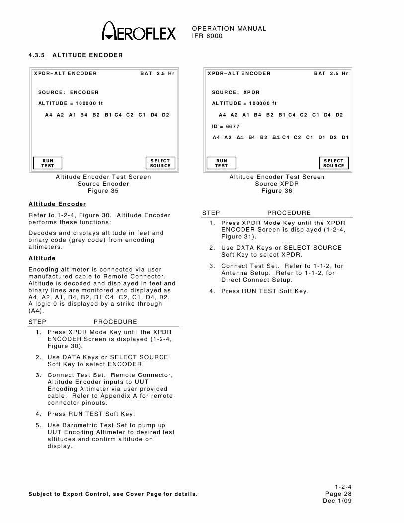
OPERATION MANUAL IFR 6000
1-2-4 Subject to Export Control , see Cover Page for deta i ls . Page 28
Dec 1/09
4.3.5 ALTITUDE ENCODER
B A T 2 .5 H r
X PD R – A L T E N C OD E R
SOU R C E : EN C O D ER AL T IT U D E = 1 0 00 0 0 f t
A 4 A 2 A 1 B 4 B 2 B 1 C 4 C 2 C 1 D4 D 2
RUN TE ST
S EL EC T SOU RCE
Al t i tude Encoder Test Screen
Source Encoder F igure 35
Alt i tude Encoder
Refer to 1-2-4, F igure 30. A l t i tude Encoder per forms these funct ions:
Decodes and d isp lays a l t i tude in feet and b inary code (grey code) f rom encoding a l t imeters.
Alt i tude
Encoding a l t imeter is connected v ia user manufactured cable to Remote Connector . A l t i tude is decoded and d isp layed in feet and b inary l ines are moni tored and d isp layed as A4, A2, A1, B4, B2, B1 C4, C2, C1, D4, D2. A log ic 0 is d isp layed by a s t r ike through (A4) .
STEP PROCEDURE
1. Press XPDR Mode Key unt i l the XPDR ENCODER Screen is d isp layed (1-2-4, F igure 30) .
2 . Use DATA Keys or SELECT SOURCE Sof t Key to se lect ENCODER.
3. Connect Test Set . Remote Connector , A l t i tude Encoder inputs to UUT Encoding Al t imeter v ia user prov ided cable. Refer to Appendix A for remote connector p inouts .
4 . Press RUN TEST Sof t Key.
5 . Use Barometr ic Test Set to pump up UUT Encoding Al t imeter to des i red test a l t i tudes and conf i rm a l t i tude on d isp lay.
B A T 2 .5 H r
X PD R – A L T E N C OD E R
SOU R C E : XP D R AL T IT U D E = 1 0 00 0 0 f t
A 4 A 2 A 1 B 4 B 2 B 1 C 4 C 2 C 1 D4 D 2 ID = 66 7 7 A 4 A 2 A 1 B4 B 2 B 1 C 4 C 2 C 1 D 4 D 2 D 1
RUN TE ST
S EL EC TSOU RCE
Al t i tude Encoder Test Screen
Source XPDR Figure 36
STEP PROCEDURE
1. Press XPDR Mode Key unt i l the XPDR ENCODER Screen is d isp layed (1-2-4, F igure 31) .
2 . Use DATA Keys or SELECT SOURCE Sof t Key to se lect XPDR.
3. Connect Test Set . Refer to 1-1-2, for Antenna Setup. Refer to 1-1-2, for Di rect Connect Setup.
4 . Press RUN TEST Sof t Key.
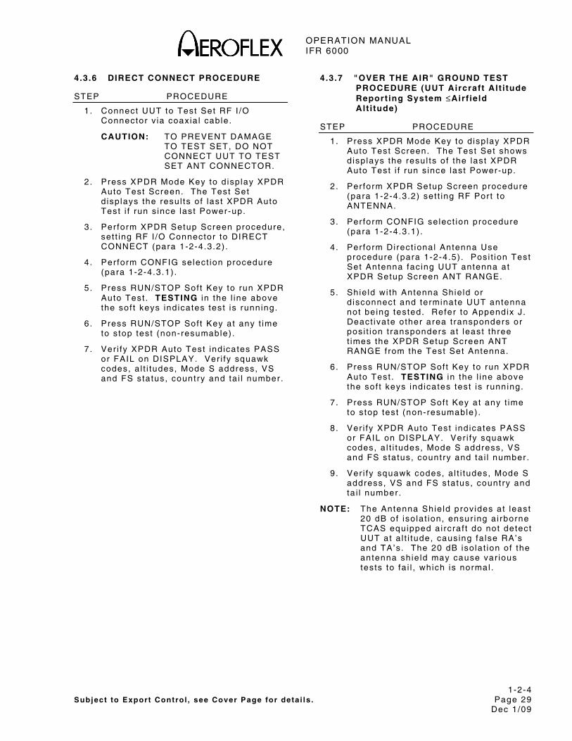
OPERATION MANUAL IFR 6000
1-2-4 Subject to Export Control , see Cover Page for deta i ls . Page 29
Dec 1/09
4.3.6 DIRECT CONNECT PROCEDURE
STEP PROCEDURE
1. Connect UUT to Test Set RF I /O Connector v ia coax ia l cable.
CAUTION: TO PREVENT DAMAGE TO TEST SET, DO NOT CONNECT UUT TO TEST SET ANT CONNECTOR.
2. Press XPDR Mode Key to d isp lay XPDR Auto Test Screen. The Test Set d isp lays the resu l ts o f las t XPDR Auto Test i f run s ince last Power-up.
3 . Per form XPDR Setup Screen procedure, set t ing RF I /O Connector to DIRECT CONNECT (para 1-2-4.3.2) .
4 . Per form CONFIG select ion procedure (para 1-2-4.3.1) .
5 . Press RUN/STOP Sof t Key to run XPDR Auto Test . TESTING in the l ine above the sof t keys ind icates test is running.
6 . Press RUN/STOP Sof t Key at any t ime to s top test (non-resumable) .
7 . Ver i fy XPDR Auto Test ind icates PASS or FAIL on DISPLAY. Ver i fy squawk codes, a l t i tudes, Mode S address, VS and FS status, country and ta i l number.
4.3.7 "OVER THE AIR" GROUND TEST PROCEDURE (UUT Aircraft Alt i tude Report ing System ≤Airf ield Al t i tude)
STEP PROCEDURE
1. Press XPDR Mode Key to d isp lay XPDR Auto Test Screen. The Test Set shows d isp lays the resul ts o f the last XPDR Auto Test i f run s ince last Power-up.
2 . Per form XPDR Setup Screen procedure (para 1-2-4.3.2) set t ing RF Por t to ANTENNA.
3. Per form CONFIG select ion procedure (para 1-2-4.3.1) .
4 . Per form Di rect ional Antenna Use procedure (para 1-2-4.5) . Pos i t ion Test Set Antenna fac ing UUT antenna at XPDR Setup Screen ANT RANGE.
5. Shie ld wi th Antenna Shie ld or d isconnect and terminate UUT antenna not be ing tested. Refer to Appendix J . Deact ivate other area t ransponders or pos i t ion t ransponders at least three t imes the XPDR Setup Screen ANT RANGE f rom the Test Set Antenna.
6 . Press RUN/STOP Sof t Key to run XPDR Auto Test . TESTING in the l ine above the sof t keys ind icates test is running.
7 . Press RUN/STOP Sof t Key at any t ime to s top test (non-resumable) .
8 . Ver i fy XPDR Auto Test ind icates PASS or FAIL on DISPLAY. Ver i fy squawk codes, a l t i tudes, Mode S address, VS and FS status, country and ta i l number.
9 . Ver i fy squawk codes, a l t i tudes, Mode S address, VS and FS status, country and ta i l number.
NOTE: The Antenna Shie ld prov ides at least 20 dB of iso la t ion, ensur ing a i rborne TCAS equipped a i rcraf t do not detect UUT at a l t i tude, caus ing fa lse RA’s and TA’s . The 20 dB iso la t ion of the antenna sh ie ld may cause var ious tests to fa i l , which is normal .

OPERATION MANUAL IFR 6000
1-2-4 Subject to Export Control , see Cover Page for deta i ls . Page 30
Dec 1/09
4.3.8 "OVER THE AIR" SIMULATED ALTITUDE TEST PROCEDURE (UUT Aircraft Alt i tude Report ing System >Airf ie ld Alt i tude ["Pumped Up"])
STEP PROCEDURE
1. Press XPDR Mode Key to d isp lay XPDR Auto Test Screen. Test Set d isp lays resul ts o f las t XPDR Auto Test i f run s ince last Power-up.
2 . Per form XPDR Setup Screen procedure, set t ing RF I /O Connector to ANTENNA (para 1-2-4.3.2) . Set ANT RANGE to ≤20 f t (6 .1 m).
3 . Per form CONFIG select ion procedure (para 1-2-4.3.1) .
4 . Per form Di rect ional Antenna procedure (para 1-2-4.5) . Posi t ion Test Set Antenna fac ing UUT antenna at XPDR Setup Screen ANT RANGE.
5. Shie ld both UUT antenna’s wi th Antenna Shie lds or d isconnect and terminate UUT Antenna not be ing tested. Deact ivate other area t ransponders or pos i t ion t ransponders >50 f t (15.24 m) f rom the Test Set antenna.
6 . Press RUN/STOP Key to run XPDR Auto Test . TESTING in the l ine above the sof t keys ind icates test is running.
7 . Press RUN/STOP Key at any t ime to s top test (non-resumable) . Otherwise, Auto Test runs unt i l a l l tests are complete.
8 . XPDR Auto Test wi l l ind icate a FAIL on DISPLAY.
9 . Ver i fy squawk codes, a l t i tudes, Mode S address, VS and FS status, country and ta i l number.
NOTE: The Antenna Shie ld prov ides at least 20 dB of iso la t ion, ensur ing a i rborne TCAS equipped a i rcraf t do not detect UUT at a l t i tude, caus ing fa lse RA’s and TA’s . The 20 dB iso la t ion of the antenna sh ie ld may cause var ious tests to fa i l , which is normal .
4.4 DME
Press DME Mode Key to se lect DME funct ional mode. DME Test Screen is d isp layed (1-2-4, F igure 32) .
B A T 2 .5 H r
% R E PL Y : 1 0 0 E C H O : OF F SQT R : O N I D EN T : OF F
T X F R EQ = 10 41 . 00 M H Z E R P= 5 5 .0 d B m P1 W ID T H = 3. 5 00 u s P R F = 1 50 H z P2 W ID T H = 3. 5 00 u s P1 - P2 = 3 6. 0 0 u s( Y )
U UT L VL = - 3 8. 2 d B m
RUNT EST
P REV P A RA M
NEX TPA RA M
D M E
STO P RAT E
V OR : 1 0 8. 0 0 M H z R F L VL : - 2 .0 d B m F R E Q: 97 8 M H z R A T E: 65 0 kt s IN CHAN: 17X RANGE: 450.00 nm
IN/ OUT
DME Screen F igure 37
DME funct ional mode has a s ing le test screen that prov ides a l l requi red contro l funct ions and measurement d isp lay. A Setup DME Screen a l lows user parameters to be entered.
User Controls:
Sof t Keys:
RUN TEST:
Star ts the DME Test . TEST RUNNING is d isp layed at the top of Screen.
NEXT PARAM:
Selects next cont ro l f ie ld . Inc ludes se lect ion of f ie lds that have dedicated Keys.
PREV PARAM:
Selects prev ious cont ro l f ie ld . Inc ludes se lect ion of f ie lds that have dedicated Keys.
STOP(START) RATE:
Stops or s tar ts Range Rate.
IN/OUT:
Reverses s imulated d i rect ion of a i rcraf t .
OPERATION MANUAL IFR 6000
1-2-4 Subject to Export Control , see Cover Page for deta i ls . Page 31
Dec 1/09
Dedicated Keys and Control Fields:
FREQ Key:
Test Set rep ly Frequency is d isp layed in three l inked uni ts .
VOR (pai red f requency MHz)
FREQ (ground to a i r f requency MHz)
CHAN (DME channel number)
Press Frequency Key to se lect each uni t in sequence. Press DATA Key to se lect X or Y channel .
RF LVL Key:
Selects RF LVL f ie ld .
Note: When swi tch ing RF por ts , RF LVL defaul ts to maximum value appropr ia te to at tenuat ion range for se lected por t .
UUT LVL f ie ld d isp lays RF leve l a t UUT antenna. Calcu lated f rom RF LVL – Path Loss + Antenna Gain – Cable Loss.
RANGE Key:
Selects Range f ie ld .
RATE Key:
Selects Rate f ie ld .
Control Fields Selected with NEXT/PREV PARAM Soft Keys:
% REPLY:
Selectab le in 1% steps. Range is 0% to 100%.
SQTR:
Selectable ON or OFF. Squi t ter must be on for DME to search and acqui re t rack.
ECHO:
Selectable ON or OFF. Mul t i -path Reply Echo s imulat ion at F ixed 30 nm, RF leve l -11 dB re la t ive to RF LVL se lected (Main Reply) .
IDENT:
Selectable ON or OFF. Sends 1350 Hz tone wi th three le t ter s ta t ion Ident i f icat ion. Def ined in Setup DME Screen (1-2-4, F igure 43) .
Measurement Parameters:
TX FREQ:
Measures and d isp lays In ter rogat ion Frequency in MHz.
ERP:
Measures and d isp lays In ter rogator ERP (Ef fect ive Radiated Power) in dBm, dBW or W peak. Uni ts are se lected in SETUP- GENERAL Screen (1-2-4, F igure 2) .
PRF:
Measures and d isp lays in ter rogator Pulse Repet i t ion Frequency.
P1 WIDTH:
Measures and d isp lays In ter rogator P1 width in us.
P2 WIDTH:
Measures and d isp lays In ter rogator P2 width in us.
P1/P2:
Measures and d isp lays in ter rogator P1 to P2 spac ing and d isp lays Mode X or Y, depending on spac ing.
Control Field Power Up Defaults:
FREQ: 978 MHz.
RF LVL (UUT LVL): Maximum
RF LVL: Maximum
RATE: 0 k ts IN
RANGE: 0 nm
% REPLY: 100
ECHO: OFF
SQTR: ON
IDENT: ON

OPERATION MANUAL IFR 6000
1-2-4 Subject to Export Control , see Cover Page for deta i ls . Page 32
Dec 1/09
4.4.1 SETUP
Setup DME
Setup DME Screen conta ins parameters which determine the operat ional character is t ics of each funct ional mode of the Test Set .
NOTE: Setup Screen in format ion is entered before conduct ing test operat ions.
B A T 2 .5 H r
P R EV P A RA M
S ET U P –D M E
DI AG
R F PO R T : DI R EC T C ON N E C T A N T R A N G E : 1 0. 5 m A NT G A I N ( d B i) I D EN T T ON E : IF R 0 .9 6 GH z : 7 .5 D I R C A B L E L O SS : 1 .2 d B 1 . 03 GH z : 7 .1 A N T C A B L E: 2 5 F T 1 . 09 GH z : 6 .1 A N T C A B L E L OS S: 4. 0 d B 1 . 15 GH z : 5 .0 M A X R A N G E: 2 00 . 00 n m 1 . 22 GH z : 2 .8
N EX T P A RA M
Setup DME Screen F igure 38
STEP PROCEDURE
1. Press SETUP Select Key to d isp lay SETUP-DME Contro l Screen (1-2-4, F igure 33) .
2 . Set fo l lowing parameters by press ing NEXT PARAM and PREV PARAM to se lect f ie ld . Use DATA Keys to s lew the data.
● RF I /O CONNECTOR:
Selects ANTENNA (ANT CONNECTOR) or DIRECT CONNECT v ia RF I /O Connector .
● DIRECT CABLE LOSS:
Entered in dB, normal ly th is is set once, f igure marked on suppl ied RF coaxia l cable (0 .0 to 9.9 dB) .
STEP PROCEDURE
● ANT CABLE:
Select ions USER DEFINED, 1 FT, 6 FT, 25 FT, 50 FT, 60 FT.
When USER DEFINED selected, cable loss may be manual ly entered by the user in ANT CABLE LOSS f ie ld . When 1, 6 , 25, 50 or 60 feet se lected, ANT CABLE LOSS f ie ld is automat ica l ly ca lcu la ted.
ANT CABLE select ion of 1 , 6 , 25, 50 or 60 feet resul ts in 0 , 0 , 68, 138 and 184 ns of de lay.
● ANT CABLE LOSS:
Disp lays antenna cable loss in dB. I f user def ined, normal ly th is is set once, f igure marked on suppl ied RF coaxia l cable (0 .0 to 9.9 dB) . I f preset length 1, 6 , 25, 50 or 60 feet is se lected, then cable loss in dB is automat ica l ly ca lcu la ted and d isp layed.
NOTE: Based on Aerof lex suppl ied cables, (25 and 50 foot cables opt ional )
NOTE: 25 and 50 foot cable se lect ion compensates for de lay of Aerof lex opt ional cables.
● ANT RANGE:
Test Set Antenna to t ransponder antenna range (6 to 250 f t or 2 .0 to 75.0 m).
NOTE: SETUP GENERAL Screen UNITS parameter determines feet or meters (1-2-4, F igure 11) .
● ANT GAIN:
Entered in dBi and normal ly set once, the f ive ga in f igures (0.0 to 20.9) for f requencies are:
0 .96 GHz 1.15 GHz 1.03 GHz 1.21 GHz 1.09 GHz
Gain f igures are a lso marked on the Di rect ional Antenna.

OPERATION MANUAL IFR 6000
1-2-4 Subject to Export Control , see Cover Page for deta i ls . Page 33
Dec 1/09
STEP PROCEDURE
● IDENT TONE:
Sets the three le t ter IDENT tone. Defaul t is IFR.
● MAX RANGE:
L imi ts the maximum s imulated range (10.00 to 450.00) Defaul t is 400 nm.
3 . Press DME Mode Key to re turn to DME Test Screen.
DME Test Guidel ines:
1. Press DME Mode Key to d isp lay DME Test Screen (1-2-4, F igure 32) .
2 . Set Test Set contro ls as fo l lows:
RF LVL (UUT LVL): Maximum Output
UUT LVL: Maximum Output
RF FREQ: To des i red channel
RANGE: 0.00 nm
RATE: STOP
IN/OUT: OUT
ECHO: OFF
SQTR: OFF
% REPLY: 70
IDENT: ON
3. Set SQTR to ON and ver i fy UUT DME searches and locks on wi th in 1 .5 sec.
4 . Ver i fy Range d isp layed on UUT DME dis tance ind icator is 0 nm (±0.5 nm).
5 . Ver i fy Track PRF is ≤30 Hz.
6 . Ver i fy TX Frequency is wi th in ±0.1 MHz of ass igned channel .
7 . Ver i fy P1 to P2 Pulse Widths are 3.5 μs (±0.5 μs) .
8 . Ver i fy P1 to P2 Pulse Spacing is : X channel 12.0 us (±0.5 μs) Y Channel 36.0 us (±0.5 μs)
9. Ver i fy ERP is for : TSO’d DME >18,000 f t ≥250 W (+54 dBm)
TSO’d DME <18,000 f t ≥50 W (+47 dBm)
STEP PROCEDURE
10. Set RATE to 600 k ts and ver i fy UUT DME dis tance ind icator d isp lays an outbound t rack, wi thout break ing lock.
11. Set IN/OUT to IN and ver i fy UUT DME dis tance ind icator d isp lays an inbound t rack, wi thout break ing lock. Set RATE to 0 k ts .
12. Set %REPLY to 0. Ver i fy d is tance cont inues to be d isp layed and f lag remains out o f v iew for 8 s (±4 sec) . Af ter memory t imes out , ver i fy on UUT DME dis tance ind icator that d is tance is not d isp layed and f lag is in v iew. Ver i fy Search PRF is ≤150 Hz.
13. Set %REPLY to 70 and RF LVL to -79 dBm, ver i fy UUT DME locks on. Set IDENT tone to ON. Ver i fy 1350 Hz Ident morse is present on UUT DME audio. Set IDENT to OFF.
14. Set RANGE to 40 nm. Set ECHO to ON. Ver i fy UUT DME does not break lock and range d isp layed on UUT DME ind icator is 40 nm (±0.5 nm). Set ECHO to OFF.
15. Set UUT LVL to -79 dBm and %REPLY to 70. Ver i fy UUT DME is locked on. Adjust UUT LVL in -1 dB steps, a l lowing 15 sec between s teps unt i l UUT DME breaks lock. Ver i fy UUT LVL is ≥ -83 dBm.
NOTE: OEM Test procedures should be fo l lowed.
NOTE: For Radiated Test ing, Maximum UUT LVL set tab le depends on d is tance of Test Set f rom UUT and Setup DME Screen set t ings.
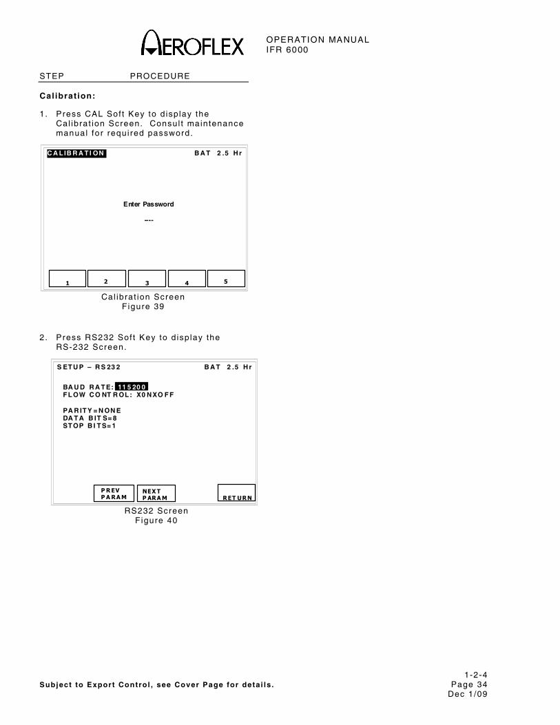
OPERATION MANUAL IFR 6000
1-2-4 Subject to Export Control , see Cover Page for deta i ls . Page 34
Dec 1/09
STEP PROCEDURE
Calibrat ion:
1. Press CAL Sof t Key to d isp lay the Cal ibrat ion Screen. Consul t maintenance manual for requi red password.
B A T 2 .5 H rC A L IB R A T I ON
Enter Password
----
2 5 1 3 4
Cal ibrat ion Screen F igure 39
2 . Press RS232 Sof t Key to d isp lay the RS-232 Screen.
B A T 2 .5 H r
P R EV P A RA M
S ET U P – R S 23 2
BA U D R A T E: 11 5 20 0 F L OW C O NT R OL : X0 N XO F F PA R IT Y = N ON E DA T A B IT S= 8 ST OP B I T S= 1
RET URN
NEX T P ARA M
RS232 Screen F igure 40

OPERATION MANUAL IFR 6000
1-2-4 Subject to Export Control , see Cover Page for deta i ls . Page 35
Dec 1/09
4.5 TCAS
The IFR 6000 fu l ly tests ATCRBS and Mode S, ACAS, TCAS I and I I (Traf f ic A ler t Col l is ion Avoidance System).
The test set s imulates an In t ruder A i rcraf t converg ing on the pos i t ion of the TCAS UUT. By manual ly def in ing a scenar io or u t i l iz ing the factory defaul t scenar ios in test set memory, the Test Set operator can ver i fy the correct TA’s (Traf f ic Advisory) and RA’s (Resolut ion Advisory) have occurred on the TCAS d isp lay.
The IFR 6000 is used wi th the d i rect ional antenna at tached, a l lowing the user to move the test set to d i f ferent locat ions and headings f rom the Ai rcraf t UUT.
4.5.1 TCAS OPERATION CONCEPT
TCAS is a system which prov ides s i tuat ional awareness of the surrounding a i rspace of an a i rcraf t to the p i lo t and crew. TCAS estab l ishes a vo lume of a i rspace around the a i rcraf t based upon range, speed and a l t i tude. Refer to 1-2-4, F igure 33.
By work ing in-conjunct ion wi th the a i rcraf t Transponder system, TCAS can determine the re la t ive threat o f an a i rcraf t and issue v isual and audib le adv isor ies to ass is t the crew in tak ing act ion that prevents a co l l is ion. Refer to 1-2-4, Table 3.
TCAS Protect ion Volume Example
5 ,000 f t to 10,000 f t F igure 41

OPERATION MANUAL IFR 6000
1-2-4 Subject to Export Control , see Cover Page for deta i ls . Page 36
Dec 1/09
Tau (sec)
DMOD (nmi)
Alt i tude Threshold ( f t )
Your Alt i tude ( f t )
SL
TA RA TA RA TA RA (ALIM)
<1000 2 20 N/A 0.30 N/A 850 N/A
1000 - 2350 3 25 15 0.33 0.20 850 300
2350 - 5000 4 30 20 0.48 0.35 850 300
5000 - 10,000 5 40 25 0.75 0.55 850 350
10,000 - 20,000 6 45 30 1.00 0.80 850 400
20,000 - 42,000 7 48 35 1.30 1.10 850 600
>42,000 7 48 35 1.30 1.10 1200 700
Protect ion Volume Parameters Versus Al t i tude Table 3

OPERATION MANUAL IFR 6000
1-2-4 Subject to Export Control , see Cover Page for deta i ls . Page 37
Dec 1/09
Typica l TCAS I I Disp lay F igure 42
Non-Threat Traff ic: An open whi te d iamond ind icates that an in t ruder ’s re la t ive a l t i tude is ±1200 f t ver t ica l ly or d is tance is beyond 6 nm range and not yet cons idered a threat .
Proximity Intruder Traff ic: A f i l led whi te d iamond ind icates that the in t rud ing a i rcraf t is ±1200 f t ver t ica l ly and wi th in 6 nm range, and s t i l l not cons idered a threat .
Traff ic Advisory: A symbol change to a f i l led ye l low c i rc le ind icates that the in t rud ing a i rcraf t is cons idered to be potent ia l ly hazardous. Depending on a l t i tude TCAS I I d isp lays a TA when the t ime to CPA is between 20 and 48 sec.
Resolut ion Advisory: A so l id red square ind icates that the in t rud ing a i rcraf t is pro jected to be a co l l is ion threat . TCAS I I ca lcu lates that the in t ruder has reached the point where a Resolut ion Advisory is necessary. The t ime to c losest approach wi th the in t ruder is now between 15 and 35 sec depending on a l t i tude. The symbol appears together wi th an appropr ia te audio warn ing and a ver t ica l maneuver ind icat ion on the RA/VSI.
Numbers: Represents the in t ruder a i rcraf t re la t ive a l t i tude ±100 f t leve ls f rom a i rcraf t .
Arrows: Ind icate i f the in t ruder a i rcraf t is ascending or descending f rom re la t ive pos i t ion.
-05

OPERATION MANUAL IFR 6000
1-2-4 Subject to Export Control , see Cover Page for deta i ls . Page 38
Dec 1/09
4.5.2 TCAS TESTING
The IFR 6000 prov ides three bas ic TCAS test funct ions.
TCAS Screen
Provides s imulated encounters wi th in t rud ing Mode S or Mode C a i rcraf t . Measures Peak Pulse Power or ERP (Ef fect ive Radiated Power) and TX Frequency of the in ter rogator .
Monitor Screens
Survei l lance Moni tor :
Disp lays surve i l lance in ter rogat ions UF0 and UF16 f ie ld content , surve i l lance in terva l and count .
Broadcast Moni tor :
Disp lays TCAS broadcast in ter rogat ions UF16 f ie ld content , broadcast in terva l and count .
Disp lays RA broadcast in ter rogat ions UF16 f ie ld content , broadcast in terva l and count .
Whisper-Shout Moni tor :
Disp lays whisper-shout sequence in terva l , count o f in ter rogat ions wi th no suppress ion, S1, P2 or both S1 and P2. In ter rogat ion spac ing is a lso d isp layed.
Setup Screens
Sets operat ional range and height f rom test set antenna to UUT antenna, cable loss, antenna gain parameters s imulated and t ransponder Mode S address.
Reply Parameters Screen a l lows contro l over Mode S DF0, DF11 and DF16 f ie ld content .
4.5.3 SETUP
SETUP-TCAS SCREEN:
SETUP-TCAS Screen conta ins parameters which determine operat ional character is t ics of the TCAS Funct ional Mode. Unless otherwise s tated, last used va lues are re ta ined on Power-Up.
NOTE: Enter Setup Screen in format ion before conduct ing test operat ions.
R F P OR T : A N T E N N A A N T R A N G E : 1 2 f t A N T H E IG H T : 1 f t U U T A D D R E SS : A U T O M A N U A L A A :0 0 00 0 0 D IR C A B L E L O SS : 1. 3 d B D IR C A B L E L O SS : 1. 2 d B A N T C A B L E : 25 F T A N T C A B L E L O S S: 4 .0 d B A N T G A IN ( d B i) SQ U IT T E R S: ON 1 .0 3 GH z: 7. 1 A L T R EP OR T I NG : O N 1. 0 9 G Hz : 6 .1 D IS PL AY ED A L T : R E L A T IV E T E ST SE T A A : A 9 24 9 3
B A T 2 .5 H r
RE PLYPA RA M
NEX T P ARA M
S ET U P -T C A S
DI AG
PR EVPA RA M
ST OR E/RE CA LL
SETUP-TCAS Screen F igure 43
STEP PROCEDURE
1. Press SETUP Select Key to d isp lay SETUP TCAS Screen (1-2-4, F igure 35) .
2 . Set fo l lowing parameters by press ing NEXT PARAM and PREV PARAM to se lect f ie ld . Use DATA Keys to s lew the data.
● RF PORT:
Selects ANTENNA or DIRECT CONNECT v ia RF I /O Connector .
● DIR CABLE LOSS:
Entered in dB, f igure (at 1090 MHz) marked on suppl ied long RF coaxia l cable.
NOTE: Cable loss range is 0 .0 to 9 .9 dB.

OPERATION MANUAL IFR 6000
1-2-4 Subject to Export Control , see Cover Page for deta i ls . Page 39
Dec 1/09
STEP PROCEDURE
● ANT CABLE:
Select ions USER DEFINED, 1 FT, 6 FT, 25 FT, 50FT, 60 FT.
When USER DEFINED selected, cable loss may be manual ly entered by the user in ANT CABLE LOSS f ie ld . When 1, 6 , 25, 50 or 60 feet se lected, ANT CABLE LOSS f ie ld is automat ica l ly ca lcu la ted.
ANT CABLE select ion of 1 , 6 , 25, 50 or 60 feet resul ts in 0 , 0 , 68, 138 and 184 ns of de lay.
● ANT CABLE LOSS:
Disp lays antenna cable loss in dB (1090 MHZ). I f user def ined, normal ly th is is set once, f igure marked on suppl ied RF coax ia l cable
NOTE: Cable loss range 0.0 to 9 .9 dB.
I f preset length 1, 6 , 25, 50 or 60 feet is se lected, then cable loss in dB is automat ica l ly ca lcu la ted and d isp layed.
NOTE: Based on Aerof lex suppl ied cables, (25 and 50 foot cables opt ional ) .
NOTE: 25 and 50 foot cable se lect ion compensates for de lay of Aerof lex opt ional cables.
● ANT GAIN:
Entered in dBi , ga in f igures (0.0 to 20.9) for 1 .03 and 1.096 GHz marked on suppl ied Di rect ional Antenna.
● ANT RANGE:
Test Set Antenna to TCAS antenna hor izonta l range (6 to 250 f t or 2 .0 to 75.0 m).
NOTE: UNITS parameter determines feet or meters.
● ANT HEIGHT:
Test Set Antenna to TCAS antenna height d i f ference (1 to 99 f t or 0 .5 to 30.0 m).
NOTE: UNITS parameter determines feet or meters.
STEP PROCEDURE
● UUT ADDRESS:
I f AUTO is se lected the test set in ter rogates the TCAS UUT Transponder wi th an ATCRBS Al l Cal l , to obta in the Mode S address, which is used in subsequent Transponder in ter rogat ions to obta in the TCAS UUT a l t i tude.
I f MANUAL is se lected, the UUT address is obta ined f rom the MANUAL AA f ie ld .
● MANUAL AA:
User entered Transponder address for TCAS UUT Transponder .
● SQUITTERS:
Used to turn ON or OFF Simulated Mode S Transponder DF11 squi t ters conta in ing address spec i f ied in TEST SET AA: f ie ld . Squi t ters are t ransmi t ted once per second and should be set to ON for normal in ter rogat ion/ rep ly operat ion.
● ALT REPORTING:
Used to turn ON or OFF Simulated Transponder ATCRBS Mode C or Mode S a l t i tude in format ion.
● DISPLAYED ALT:
Wi th RELATIVE selected, s imulated a l t i tude d isp layed in ALT f ie ld o f TCAS screen is re la t ive to UUT Al t i tude ( i .e . , ± UUT a l t i tude) . Wi th ABSOLUTE selected, s imulated a l t i tude d isp layed in ALT f ie ld o f TCAS screen is actua l a l t i tude.
● TEST SET AA:
Enter test set s imulated Mode S Transponder address in HEX.
3 . Press TCAS Mode Key to return to TCAS Test Screen.

OPERATION MANUAL IFR 6000
1-2-4 Subject to Export Control , see Cover Page for deta i ls . Page 40
Dec 1/09
TCAS REPLY PARAMETERS SCREEN:
Press SETUP SELECT Key unt i l TCAS-SETUP screen is d isp layed. Press REPLY PARAM Sof t Key to d isp lay TCAS Reply Param Screen (1-2-4, F igure 36) .
DF 0 V S : 0 SL : 0 DF 11 C A : 0 DF 16 VS : 0 SL :0 R Ia : 8 R It : 3 A R A : 00 0 0 R A C : 0 VD S : 30
B A T 2 .5 H r
PR EV P ARA M
T C A S- R EPL Y PA R A M
RET URNNEX T
PA RA M RES ET
PA RA MS
TCAS Reply Parameters Screen F igure 44
The rep ly parameters screen contro ls the content o f the Mode S Repl ies DF0, DF11 and DF16 used in the TCAS test . The message f ie lds a l low the user to program capabi l i ty in format ion and var ious adv isor ies to the TCAS in terrogator .
NOTE: Refer to Appendix I for deta i led descr ip t ions of the fo l lowing d isp layed Downl ink Format (DF) f ie lds and subf ie lds. A l l f ie lds are d isp layed in hexadecimal . Unless otherwise spec i f ied, both s ing le and cont inuous SLEW key depress ions change va lues by 1.
USER CONTROL SOFT KEYS
NEXT PARAM:
Selects next cont ro l f ie ld , inc lud ing se lect ion of f ie lds that have dedicated keys.
PREV PARAM:
Selects prev ious cont ro l f ie ld , inc lud ing se lect ion of f ie lds that have dedicated keys.
RESET PARAMS:
Resets a l l parameters to factory defaul t .
RETURN:
Displays the SETUP-TCAS screen.
CONTROL FIELD SOFT KEYS
VS:
Enter ver t ica l s ta tus. VS: f ie ld ind icates in t rud ing a i rcraf t is a i rborne when ‘0 ’ or on the ground when ‘1 ’ . The VS: f ie ld is t ransmi t ted in DF0 and DF16.
SL:
Enter s imulated IFR 6000 Sensi t iv i ty Level (1-2-4, Table 4)
NOTE:The SL: f ie ld conta ins s imulated sens i t iv i ty leve l in format ion and does not actua l ly set the IFR 6000 to a par t icu lar Sensi t iv i ty Level .
INPUT DATA
DEFINITION
0 No Sensit iv i ty Level reported
1 Operates at Sensit iv i ty Level 1
2 Operates at Sensit iv i ty Level 2
3 Operates at Sensit iv i ty Level 3
4 Operates at Sensit iv i ty Level 4
5 Operates at Sensit iv i ty Level 5
6 Operates at Sensit iv i ty Level 6
7 Operates at Sensit iv i ty Level 7
SL: F ie ld Val id Data Table 4
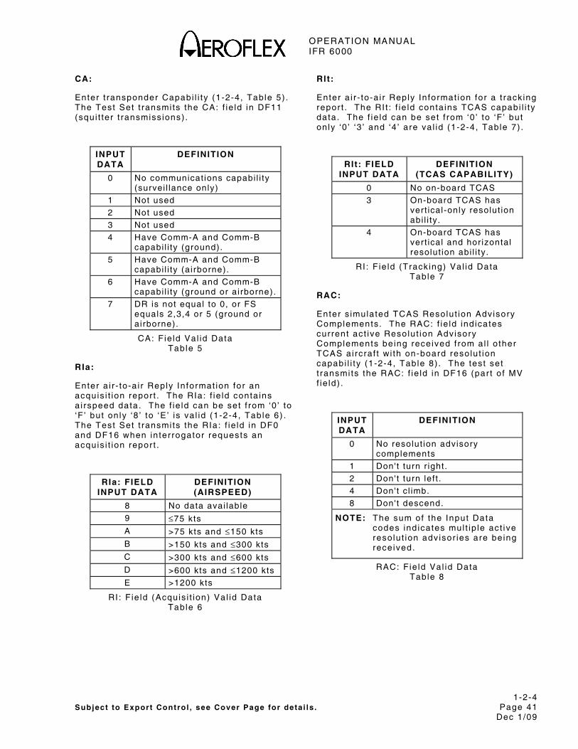
OPERATION MANUAL IFR 6000
1-2-4 Subject to Export Control , see Cover Page for deta i ls . Page 41
Dec 1/09
CA:
Enter t ransponder Capabi l i ty (1-2-4, Table 5) . The Test Set t ransmi ts the CA: f ie ld in DF11 (squi t ter t ransmiss ions) .
INPUT DATA
DEFINITION
0 No communicat ions capabi l i ty (survei l lance only)
1 Not used
2 Not used
3 Not used
4 Have Comm-A and Comm-B capabi l i ty (ground).
5 Have Comm-A and Comm-B capabi l i ty (airborne).
6 Have Comm-A and Comm-B capabi l i ty (ground or airborne).
7 DR is not equal to 0, or FS equals 2,3,4 or 5 (ground or airborne).
CA: F ie ld Val id Data Table 5
RIa:
Enter a i r - to-a i r Reply In format ion for an acquis i t ion repor t . The RIa: f ie ld conta ins a i rspeed data. The f ie ld can be set f rom ‘0 ’ to ‘F ’ but on ly ‘8 ’ to ‘E ’ is va l id (1-2-4, Table 6) . The Test Set t ransmi ts the RIa: f ie ld in DF0 and DF16 when in ter rogator requests an acquis i t ion repor t .
RIa: FIELD INPUT DATA
DEFINITION (AIRSPEED)
8 No data avai lable
9 ≤75 kts
A >75 kts and ≤150 kts
B >150 kts and ≤300 kts
C >300 kts and ≤600 kts
D >600 kts and ≤1200 kts
E >1200 kts
RI : F ie ld (Acquis i t ion) Val id Data Table 6
Rlt:
Enter a i r - to-a i r Reply In format ion for a t rack ing repor t . The RI t : f ie ld conta ins TCAS capabi l i ty data. The f ie ld can be set f rom ‘0 ’ to ‘F ’ but on ly ‘0 ’ ‘3 ’ and ‘4 ’ are va l id (1-2-4, Table 7) .
RIt: FIELD INPUT DATA
DEFINITION (TCAS CAPABILITY)
0 No on-board TCAS
3 On-board TCAS has vert ical-only resolut ion abi l i ty.
4 On-board TCAS has vert ical and hor izontal resolut ion abi l i ty.
RI : F ie ld (Track ing) Val id Data Table 7
RAC:
Enter s imulated TCAS Resolut ion Advisory Complements. The RAC: f ie ld ind icates current act ive Resolut ion Advisory Complements be ing received f rom a l l o ther TCAS ai rcraf t wi th on-board resolut ion capabi l i ty (1-2-4, Table 8) . The test set t ransmi ts the RAC: f ie ld in DF16 (par t o f MV f ie ld) .
INPUT DATA
DEFINITION
0 No resolut ion advisory complements
1 Don't turn r ight.
2 Don't turn lef t .
4 Don't c l imb.
8 Don't descend.
NOTE: The sum of the Input Data codes ind icates mul t ip le act ive resolut ion adv isor ies are be ing received.
RAC: Fie ld Val id Data Table 8
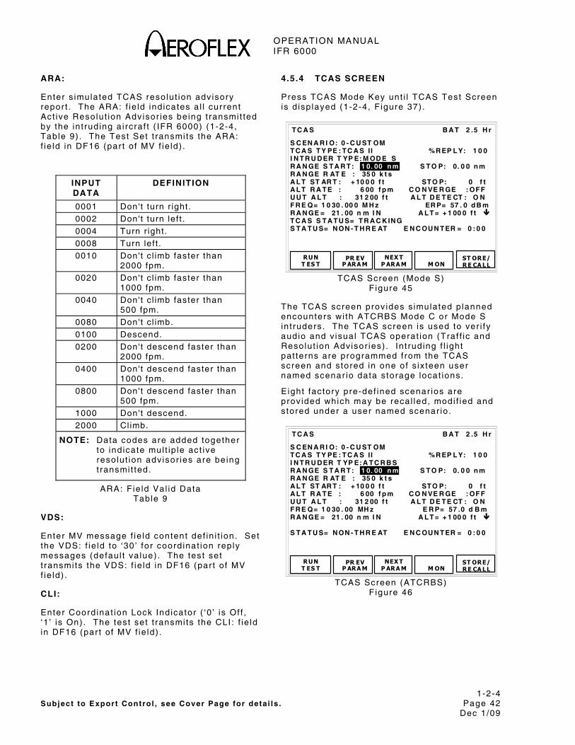
OPERATION MANUAL IFR 6000
1-2-4 Subject to Export Control , see Cover Page for deta i ls . Page 42
Dec 1/09
ARA:
Enter s imulated TCAS resolut ion adv isory repor t . The ARA: f ie ld ind icates a l l current Act ive Resolut ion Advisor ies be ing t ransmi t ted by the in t rud ing a i rcraf t ( IFR 6000) (1-2-4, Table 9) . The Test Set t ransmi ts the ARA: f ie ld in DF16 (par t o f MV f ie ld) .
INPUT DATA
DEFINITION
0001 Don't turn r ight.
0002 Don't turn lef t .
0004 Turn r ight.
0008 Turn lef t .
0010 Don't c l imb faster than 2000 fpm.
0020 Don't c l imb faster than 1000 fpm.
0040 Don't c l imb faster than 500 fpm.
0080 Don't c l imb.
0100 Descend.
0200 Don't descend faster than 2000 fpm.
0400 Don't descend faster than 1000 fpm.
0800 Don't descend faster than 500 fpm.
1000 Don't descend.
2000 Cl imb.
NOTE: Data codes are added together to ind icate mul t ip le act ive resolut ion adv isor ies are be ing t ransmi t ted.
ARA: F ie ld Val id Data Table 9
VDS:
Enter MV message f ie ld content def in i t ion. Set the VDS: f ie ld to ‘30 ’ for coord inat ion rep ly messages (defaul t va lue) . The test set t ransmi ts the VDS: f ie ld in DF16 (par t o f MV f ie ld) .
CLI:
Enter Coord inat ion Lock Ind icator ( ‘0 ’ is Of f , ‘1 ’ is On) . The test set t ransmi ts the CLI : f ie ld in DF16 (par t o f MV f ie ld) .
4.5.4 TCAS SCREEN
Press TCAS Mode Key unt i l TCAS Test Screen is d isp layed (1-2-4, F igure 37) .
B A T 2 .5 H r
S C EN A R I O: 0 - C U ST OM T C A S T Y PE : T C A S I I %R EP L Y: 1 0 0 I N T R U D ER T YP E: M OD E S R A N GE S T A R T : 1 0. 00 n m S T O P: 0. 0 0 n m R A N GE R AT E : 35 0 k t s A L T ST AR T : + 10 0 0 f t ST O P: 0 f t A L T R A T E : 6 00 f p m C O N VE R GE : OF F U U T A L T : 31 2 00 f t A L T D E T E CT : O N F R E Q= 1 0 30 . 00 0 M H z ER P= 57 . 0 d B m R A N GE = 21 . 00 n m I N A L T = + 1 00 0 f t T C A S S T A T U S= T R A C K IN G S T A T U S= N ON - T H R E AT E N C OU N T ER = 0 : 0 0
RUNT ES T
PR EVP ARA M
NEX T P ARA M
T C A S
M ON
ST ORE/R E CA LL
TCAS Screen (Mode S)
F igure 45
The TCAS screen prov ides s imulated p lanned encounters wi th ATCRBS Mode C or Mode S in t ruders. The TCAS screen is used to ver i fy audio and v isual TCAS operat ion (Traf f ic and Resolut ion Advisor ies) . In t rud ing f l ight pat terns are programmed f rom the TCAS screen and s tored in one of s ix teen user named scenar io data s torage locat ions.
E ight factory pre-def ined scenar ios are prov ided which may be recal led, modi f ied and s tored under a user named scenar io .
S C EN A R I O: 0 - C U ST OM T C A S T Y PE : T C A S I I %R EP L Y: 1 0 0 I N T R U D ER T YP E: A T C R B S R A N GE S T A R T : 1 0. 00 n m S T O P: 0. 0 0 n m R A N GE R AT E : 35 0 k t s A L T ST AR T : + 10 0 0 f t ST O P: 0 f t A L T R A T E : 6 00 f p m C O N VE R GE : OF F U U T A L T : 31 2 00 f t A L T D E T E CT : O N F R E Q= 1 0 30 . 00 MH z E R P= 57 .0 d B m R A N GE = 21 . 00 n m I N A L T = + 1 00 0 f t S T A T U S= N ON - T H R E AT E N C OU N T ER = 0 : 0 0
B A T 2 .5 H r
RUNT ES T
PR EVP ARA M
NEX T P ARA M
T C A S
M ON
ST ORE/R E CA LL
TCAS Screen (ATCRBS)
F igure 46

OPERATION MANUAL IFR 6000
1-2-4 Subject to Export Control , see Cover Page for deta i ls . Page 43
Dec 1/09
Calculat ion of Scenarios:
Ex: Assume in t ruder at 10,000 f t above UUT a l t i tude. In t ruder ve loc i ty is 600 k ts and in t ruder d is tance is 20 nm.
Manual ca lcu la t ion of a l t i tude rate to ensure convergence:
Select CONVERGE: OFF
STOP ALT= 0 f t , STOP RANGE= 0 nm.
ALT RATE= ALT START x RANGE RATE START RANGE x 60
ALT RATE= 10,000 x 600 20 x 60
ALT RATE = 5000 fpm
Auto ca lcu lat ion of a l t i tude rate to ensure convergence:
Set the fo l lowing:
RANGE START: 20 nm
RANGE RATE: 600 k ts
ALT START: +10,000 f t
Select CONVERGE: ON. A l t i tude rate is automat ica l ly determined to achieve co l l is ion. STOP (Range) and STOP (Al t ) f ie lds is c leared, a l lowing easy programming of random but converg ing scenar ios.
STEP PROCEDURE
1. Refer to para 1-2-4.7 for Di rect ional Antenna use and setup procedure.
2 . Press TCAS Mode Key to d isp lay TCAS Test Screen (1-2-4, F igure 37) .
3 . Set fo l lowing parameters by press ing NEXT PARAM and PREV PARAM to se lect f ie ld . Use DATA Keys to s lew the data.
USER CONTROLS SOFT KEYS
RUN TEST:
Star ts the TCAS Test .
NEXT PARAM:
Selects next cont ro l f ie ld . Inc ludes se lect ion of f ie lds that have dedicated Keys.
PREV PARAM:
Selects prev ious cont ro l f ie ld . Inc ludes se lect ion of f ie lds that have dedicated Keys.
MON:
Selects the Surve i l lance or Broadcast Moni tor Screens.
STORE/RECALL:
Selects the Setup-Scenar io Data Screen.
DEDICATED KEYS AND CONTROL FIELDS
RANGE:
RANGE Keys change RANGE.
RATE:
RATE Keys change RATE in 1kt s teps (0 to 1200 kts) .
CONTROL FIELDS SOFT KEYS
STORE/RECALL:
Selects Custom, Predef ined or User def ined scenar ios.
TCAS TYPE:
Select ions are TCAS I or TCAS I I .
% REPLY:
Selects s imulated t ransponder % reply . Selectab le in 1% steps. Range is 0 to 100%.

OPERATION MANUAL IFR 6000
1-2-4 Subject to Export Control , see Cover Page for deta i ls . Page 44
Dec 1/09
STEP PROCEDURE
INTRUDER TYPE:
Selects in t ruder type MODE S or ATCRBS.
RANGE START:
Selects s tar t range of scenar io in nm. Range is Mode S, 0 .00 to 260.00 nm or ATCRBS, 0.35 to 260.00.
RANGE STOP:
Selects s top range of scenar io in nm. Range is Mode S, 0 .00 to 260.00 nm or ATCRBS, 0.35 to 260.00.
RANGE RATE:
Selects range rate of scenar io (0 to 1200 k ts) .
ALT START:
Selects s tar t a l t i tude of scenar io in f t . Range is +127,700 f t .
NOTE: In a l l IFR 6000 TCAS scenar ios, a l t i tude START and STOP parameters are Relat ive to UUT a l t i tude, enabl ing scenar ios to be used at any a l t i tude wi thout reprogramming.
ALT STOP:
Selects s top a l t i tude of scenar io in f t . Range is +127,700 f t .
NOTE: In a l l IFR 6000 TCAS scenar ios, a l t i tude START and STOP parameters are re la t ive to UUT a l t i tude, enabl ing scenar ios to be used at any a l t i tude wi thout reprogramming.
ALT RATE:
Selects a l t i tude rate of scenar io in fpm. Range is 0 to 10000 fpm.
CONVERGE:
When converge is ON, a l t i tude rate is automat ica l ly ca lcu la ted to achieve co l l is ion at 0 nm and 0 f t ( re la t ive to UUT). Range STOP and Al t STOP f ie lds are b lanked when converge is ON.
STEP PROCEDURE
UUT ALT:
Displays s imulated in t ruder a l t i tude in f t . Th is is e i ther entered v ia the TCAS Screen or is obta ined automat ica l ly f rom the TCAS UUT t ransponder when ALT DETECT is set to ON.
ALT DETECT:
When set to ON, UUT a l t i tude is obta ined automat ica l ly f rom TCAS UUT t ransponder .
FREQ:
Displays TCAS UUT t ransmi t ter f requency in MHz.
ERP:
Displays TCAS UUT t ransmi t ter ERP (Ef fect ive Radiated Power) in dBm, dBW or W peak.
RANGE:
Displays s imulated range in nm.
ALT:
Displays s imulated a l t i tude. Depending on setup TCAS menu DISPLAYED ALT set t ing, a l t i tude d isp layed is e i ther re la t ive to UUT ALT or actual a l t i tude.
NOTE: In a l l IFR 6000 TCAS scenar ios, a l t i tude START and STOP parameters are re la t ive to UUT a l t i tude, enabl ing scenar ios to be used at any a l t i tude wi thout reprogramming.
TCAS STATUS:
Displays TCAS status e i ther ACQUIRING or TRACKING. When TRACKING is annunciated, an in t ruder should be d isp layed on the TCAS d isp lay (Mode S feature) .
NOTE: ACQUIRING or TRACKING is determined f rom UF0 or UF16 d iscrete in ter rogat ions AQ f ie ld .

OPERATION MANUAL IFR 6000
1-2-4 Subject to Export Control , see Cover Page for deta i ls . Page 45
Dec 1/09
STEP PROCEDURE
STATUS:
Displays s imulated test set s ta tus in re la t ionship to TCAS UUT. Four d i f ferent s ta tus messages may be d isp layed.
“NON THREAT”
Range is >4 nm and t ime unt i l encounter is >40 s .
“PROXIMITY”
Range is 4 nm and t ime unt i l encounter is >40 sec.
“TRAFFIC”
Time unt i l encounter is 40 sec and >25 sec.
“RESOLUTION”
Time unt i l encounter is 25 sec.
ENCOUNTER:
Displays t ime in minutes and seconds to encounter .
NOTE: There are usual ly two to three seconds of de lay ( target acquis i t ion t ime) between the s tar t o f TCAS operat ion and when the UUT acqui res the test set as a target .
When any UUT antenna is be ing tested the target acquis i t ion t ime increases. Refer to Appendix K for target acquis i t ion t ime probabi l i t ies .
5 . Press RUN Sof t Key to s tar t tes t .
4.5.5 SETUP-SCENARIO DATA SCREEN
The SETUP-SCENARIO DATA Screen may be accessed f rom e i ther the TCAS Screen or SETUP-TCAS Screen by press ing the STORE/RECALL Sof t Key.
The Setup Scenar io Screen a l lows the recal l o f n ine factory predetermined scenar ios and the Storage and Recal l o f up to 16 user def ined and named scenar ios.
B A T 2 .5 H r
1 L a st Po w e r D o w n 2 + 3 50 0 f t c o l l is i o n 3 – 35 0 0 f t c o ll is io n 4 + 3 50 0 f t f l y- b y 5 – 35 0 0 f t f l y- b y 6 + 2 00 f t co l l i si o n 7 – 20 0 f t c o l l i si o n 8 + 2 00 f t f ly - b y 9 – 20 0 f t f l y- b y 10 11 12
S TORE
SET U P- S C EN A R IO D AT A
R ET URN
N EX TP A GE
PR EV PA GE
Setup Scenar io Screen
F igure 47
USER CONTROL SOFT KEYS
STORE:
To store a spec i f ic scenar io , use the Data Select Keys to h igh l ight user s torage locat ions 10 to 25. Press STORE Sof t Key to d isp lay SETUP-STORE NAME. Use the Data Select Keys to h igh l ight des i red character .
B A T 2 .5 H r
A B C D EF G H IJ K L M N OP QR S T U VW X YZ a b c d e f g h ij kl mn o p q rs tu vw xy z 0 12 3 45 6 78 9 ! ” ’ ( ) * , - . / : ; ? @ _ __ _ __ _ __ __ _ _ __ _ __ _ __ _ __ _ __ _ _ Pl e as e E n t er S t o re N a me
E NTE RC HA R
S ELEC T
SET U P- S T OR E N A M E
C A NC ELB A CK
S P AC E
Setup Store Name Screen F igure 48

OPERATION MANUAL IFR 6000
1-2-4 Subject to Export Control , see Cover Page for deta i ls . Page 46
Dec 1/09
CHAR SELECT:
Press CHAR SELECT Sof t Key to se lect character . Repeat unt i l a l l characters have been se lected.
ENTER:
Press ENTER Sof t Key to s tore name and data. Use backspace key to change any prev ious character se lect ion.
CANCEL:
Press CANCEL Sof t Key to cancel s torage operat ion.
RECALL:
To recal l a spec i f ic scenar io use the Data Select Keys to se lect a spec i f ic scenar io . Press the RECALL Sof t Key.
RETURN:
Press the RETURN Sof t Key to d isp lay the prev ious screen.
NOTE: Scenar ios are a lso se lected by us ing the DATA KEYS when in the scenar io f ie ld of the TCAS screen.
OVERWRITE EXISTING SCENARIO:
To overwr i te an ex is t ing TCAS scenar io , press YES Sof t Key on CONFIRM Screen.
B A T 2 .5 H r
Y ES
C ON F IR M
Ov er wr i t e e x is t in g s t o re ?
NO
Conf i rm Screen F igure 49
Enter password by press ing the Sof t Keys on the SETUP-TCAS SCENARIO Screen.
B A T 2 .5 H r SE T U P- T C A S S C EN A R I O
Enter Password
----
2 51 3 4
Setup-TCAS Scenar io Screen F igure 50
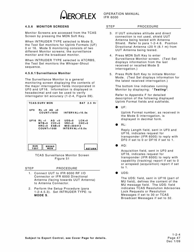
OPERATION MANUAL IFR 6000
1-2-4 Subject to Export Control , see Cover Page for deta i ls . Page 47
Dec 1/09
4.5.6 MONITOR SCREENS
Moni tor Screens are accessed f rom the TCAS Screen by press ing the MON Sof t Key.
When INTRUDER TYPE selected is Mode S, the Test Set moni tors for Upl ink Formats (UF) 0 or 16. Mode S moni tor ing consis ts o f two d i f ferent Moni tor screens; the surve i l lance moni tor and the broadcast moni tor .
When INTRUDER TYPE selected is ATCRBS, the Test Set moni tors the Whisper-Shout sequence.
4.5.6.1 Survei l lance Monitor
The Survei l lance Moni tor is a genera l moni tor ing screen d isp lay ing the contents o f the major in ter rogat ion f ie lds incorporated in UF0 and UF16. In format ion is d isp layed in hexadecimal and can be used to ver i fy in ter rogator b i t accuracy (1-2-4, F igure 39) .
B A T 2 .5 H r
U F 0 R L = 0 AQ =0 C O U N T = 10 0 0 I N T ER V A L = 10 . 0s U F 16 R L =1 A Q = 0 U D S= 0 L C K = 0 M T B = 0 C VC = 0 VR C = 0 C H C = 0 H R C = 0 E SB = 0 MI D = 35 6 41 2 C OU N T = 1 0 00 IN T E R V AL =1 0 .0 s
RUN T ES T
B ROA D MO N
T C A S- S U R V M ON
RET URN
TCAS Survei l lance Moni tor Screen F igure 51
STEP PROCEDURE
1. Connect UUT to IFR 6000 RF I /O Connector or IFR 6000 Di rect ional Antenna ( fac ing towards UUT Antenna) to Antenna Connector .
2 . Per form the Setup Procedure (para 1-2-4.5.3) . Set INTRUDER TYPE: to MODE S .
STEP PROCEDURE
3. I f UUT s imulates a l t i tude and d i rect connect ion is not used, sh ie ld UUT Antenna being tested wi th Antenna Shie ld . Refer to para 1-2-4.6. Posi t ion Di rect ional Antenna ≤20 f t (6 .1 m) f rom UUT Antenna being tested.
4 . Press MON Sof t Key to enter Survei l lance Moni tor screen. (Test Set d isp lays in format ion f rom the last received or recal led Mode S in ter rogat ion. )
5 . Press RUN Sof t Key to in i t ia te Moni tor Mode. (Test Set d isp lays in format ion for the la test received in ter rogat ion. )
The bot tom l ine ind icates running Moni tor by d isp lay ing: *Testing* .
Refer to Appendix F for deta i led descr ip t ion of the fo l lowing d isp layed Upl ink Format f ie lds and subf ie lds.
● UF:
Upl ink Format number, as received in the Mode S in ter rogat ion, is d isp layed in dec imal form.
● RL:
Reply Length f ie ld , sent in UF0 and UF16, ind icates request for t ransponder ( IFR 6000) to rep ly wi th DF0 i f set to 0 or DF16 i f set to 1.
● AQ:
Acquis i t ion f ie ld , sent in UF0 and UF16, ind icates request for t ransponder ( IFR 6000) to rep ly wi th capabi l i ty ( t rack ing) repor t i f set to 0 or a i rspeed (acquis i t ion) repor t i f set to 1.
● UDS:
The UDS: f ie ld , sent in UF16 (par t o f MU f ie ld) , def ines the content o f the MU message f ie ld . The UDS: f ie ld ind icates TCAS Resolut ion Advisor ies Lock Requests or Resolut ion Messages i f set to 30 or TCAS Broadcast Messages i f set to 32.

OPERATION MANUAL IFR 6000
1-2-4 Subject to Export Control , see Cover Page for deta i ls . Page 48
Dec 1/09
STEP PROCEDURE
● LCK:
I f set to 1 , the Lock f ie ld ind icates request for the t ransponder ( IFR 6000) to send in format ion for TCAS Resolut ion Advisory ( t ransponder is a co l l is ion threat to the in ter rogator) and is received in UF16 (par t o f MU f ie ld) .
● MTB:
I f set to 1 the Mul t ip le Threat B i t received in UF16 (par t o f MU f ie ld) ind icates the in ter rogator is receiv ing more than one co l l is ion threat .
● CVC:
The Cancel Ver t ica l Resolut ion Advisory Complement is rece ived in UF16 (par t o f MU f ie ld) (1-2-4, Table 10) .
CVC: FIELD DEFINITION
0 No cancel lat ion
1 Cancel, don't descend.
2 Cancel, don't c l imb.
CVC: Fie ld Disp lay Data Table 10
● VRC:
The Ver t ica l Resolut ion Advisory Complement is received in UF16 (par t o f MU f ie ld) (1-2-4, Table 11) .
VRC: FIELD DEFINITION
0 No complement sent
1 Don't descend.
2 Don't c l imb.
VRC: Fie ld Disp lay Data Table 11
STEP PROCEDURE
● CHC:
The Cancel Hor izonta l Resolut ion Advisory Complement is rece ived in UF16 (par t o f MU f ie ld) (1-2-4, Table 12) .
CHC: FIELD DEFINITION
0 No cancel lat ion
1 Cancel, don't turn lef t .
2 Cancel, don't turn r ight.
CHC: Fie ld Disp lay Data Table 12
● HRC:
Refer to 1-2-4, Table 13 for the Hor izonta l Resolut ion Advisory Complement received in UF16 (par t o f MU f ie ld) .
HRC: FIELD DEFINITION
0 No complement sent
1 Intruder TCAS sense is turn lef t /Don't turn lef t .
2 Intruder TCAS sense is turn lef t /Don't turn r ight.
5 Intruder TCAS sense is turn r ight/Don't turn lef t .
6 Intruder TCAS sense is turn r ight/Don't turn r ight.
HRC: Fie ld Disp lay Data Table 13

OPERATION MANUAL IFR 6000
1-2-4 Subject to Export Control , see Cover Page for deta i ls . Page 49
Dec 1/09
STEP PROCEDURE
● ESB:
Refer to 1-2-4, Table 14 for the Encoded/Ver t ica l Sense Bi ts received in UF16 (now VSB, par t o f MU f ie ld) to ver i fy Ver t ica l Resolut ion Advisory Complements .
CVC: FIELD
VRC: FIELD
VALID ESB: FIELD
0 0 0
0 1 E
0 2 7
0 3 9
1 0 B
1 1 5
1 2 C
1 3 2
2 0 D
2 1 3
2 2 A
2 3 4
3 0 6
3 1 8
3 2 1
3 3 F
ESB: F ie ld Disp lay Data Table 14
● MID:
The MID: f ie ld , rece ived in UF16 (par t o f MU f ie ld) d isp lays the d iscrete Mode S address of the TCAS in terrogator .
STEP PROCEDURE
● INTERVAL:
The IFR 6000 d isp lays t ime f rom the s tar t o f one in ter rogat ion to the s tar t o f the next in ter rogat ion. The IFR 6000 looks for the in terva l between 0.53 sec ( t ime to d isp lay in format ion) and 1.27 sec (1 .0 sec is nominal ) .
● COUNT:
The COUNT: f ie ld d isp lays the number of TCAS Survei l lance In ter rogat ions received dur ing the test operat ion.
6 . Press STOP Sof t Key to terminate test operat ion.
4.5.6.2 BROADCAST MONITOR
The Broadcast Moni tor ver i f ies the TCAS Broadcast is t ransmi t ted in UF16 approx imate ly every ten seconds. The Test Set detects a TCAS Broadcast when the AA address f ie ld decoded f rom the AP f ie ld in UF16 has a l l ones. The Broadcast Moni tor a lso ver i f ies the RA Broadcast content (1-2-4, F igure 40) .
B A T 2 .5 H r
R A B R O AD C A S T U D S= 3 1 C A C = 1 00 0 00 f t R AT =1 A R A = 1 11 01 0 1 00 00 0 0 0 MT E= 1 R AC = 1 0 10 A ID = 7 77 7 C OU N T = 10 0 0 T C A S B R OA D C A ST U D S= 3 2 M ID = A 9 24 9 2 C OU N T = 10 0 0 IN T ER V AL =1 0 .0 s
RUNT ES T
SURVMO N
T C A S- B R D C A S T M O N
RET URN
TCAS Broadcast Moni tor Screen F igure 52
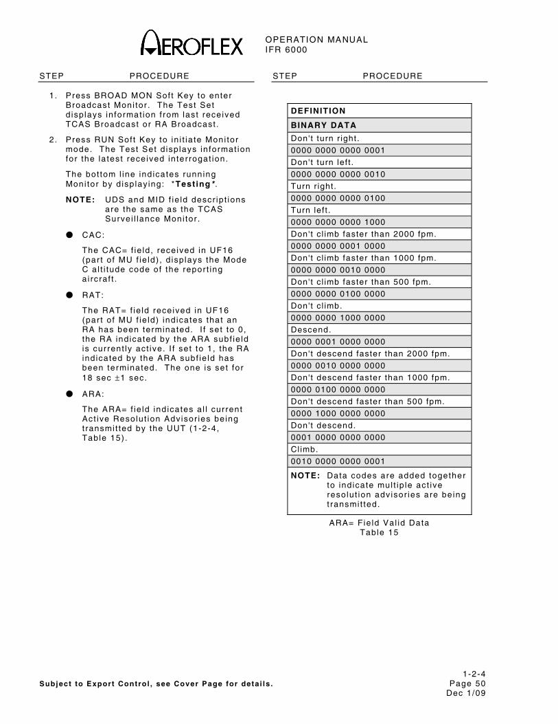
OPERATION MANUAL IFR 6000
1-2-4 Subject to Export Control , see Cover Page for deta i ls . Page 50
Dec 1/09
STEP PROCEDURE
1. Press BROAD MON Sof t Key to enter Broadcast Moni tor . The Test Set d isp lays in format ion f rom last rece ived TCAS Broadcast or RA Broadcast .
2 . Press RUN Sof t Key to in i t ia te Moni tor mode. The Test Set d isp lays in format ion for the la test received in ter rogat ion.
The bot tom l ine ind icates running Moni tor by d isp lay ing: *Testing* .
NOTE: UDS and MID f ie ld descr ip t ions are the same as the TCAS Survei l lance Moni tor .
● CAC:
The CAC= f ie ld , rece ived in UF16 (par t o f MU f ie ld) , d isp lays the Mode C a l t i tude code of the repor t ing a i rcraf t .
● RAT:
The RAT= f ie ld received in UF16 (par t o f MU f ie ld) ind icates that an RA has been terminated. I f set to 0, the RA ind icated by the ARA subf ie ld is current ly act ive. I f set to 1, the RA ind icated by the ARA subf ie ld has been terminated. The one is set for 18 sec ±1 sec.
● ARA:
The ARA= f ie ld ind icates a l l current Act ive Resolut ion Advisor ies be ing t ransmi t ted by the UUT (1-2-4, Table 15) .
STEP PROCEDURE
DEFINITION
BINARY DATA
Don't turn r ight.
0000 0000 0000 0001
Don't turn lef t .
0000 0000 0000 0010
Turn r ight.
0000 0000 0000 0100
Turn lef t .
0000 0000 0000 1000
Don't c l imb faster than 2000 fpm.
0000 0000 0001 0000
Don't c l imb faster than 1000 fpm.
0000 0000 0010 0000
Don't c l imb faster than 500 fpm.
0000 0000 0100 0000
Don't c l imb.
0000 0000 1000 0000
Descend.
0000 0001 0000 0000
Don't descend faster than 2000 fpm.
0000 0010 0000 0000
Don't descend faster than 1000 fpm.
0000 0100 0000 0000
Don't descend faster than 500 fpm.
0000 1000 0000 0000
Don't descend.
0001 0000 0000 0000
Cl imb.
0010 0000 0000 0001
NOTE: Data codes are added together to ind icate mul t ip le act ive resolut ion adv isor ies are be ing t ransmi t ted.
ARA= Fie ld Val id Data Table 15

OPERATION MANUAL IFR 6000
1-2-4 Subject to Export Control , see Cover Page for deta i ls . Page 51
Dec 1/09
STEP PROCEDURE
● RAC:
The RAC= f ie ld ind icates current act ive Resolut ion Advisory Complements be ing received f rom a l l o ther TCAS ai rcraf t wi th on-board resolut ion capabi l i ty (1-2-4, Table 16) .
DATA DEFINITION
0 No resolut ion advisory complements
1 Don't turn r ight.
2 Don't turn lef t .
4 Don't c l imb.
8 Don't descend.
NOTE: The sum of the Input Data codes ind icates mul t ip le act ive resolut ion adv isor ies are be ing received.
RAC= Fie ld Val id Data Table 16
● MTE:
The MTE= f ie ld , received in UF16 (par t o f MU f ie ld) , ind icates i f two or more s imul taneous threats are current ly be ing processed by the TCAS threat resolut ion log ic . 0= One threat is be ing processed by the resolut ion log ic (when ARA bi t 41=1) ; or no threat is be ing processed by the resolut ion log ic (when ARA b i t 41=0) . 1= Two or more s imul taneous threats are be ing processed by the resolut ion log ic .
● AID:
The AID= f ie ld , received in UF16 (par t o f MU f ie ld) , d isp lays the Mode A ident i ty code of the repor t ing a i rcraf t .
● INTERVAL:
The INTERVAL= f ie ld d isp lays the t ime in terva l , in seconds, between the la test two TCAS Broadcast Messages received (nominal ly 10 sec for each in ter rogator) .
STEP PROCEDURE
NOTE: TCAS Broadcast Messages are j i t tered ±0.2 sec of f the nominal 10 sec in terva l t ime. The TCAS Broadcast Message may a lso be s taggered between the d i rect ional antennas caus ing shor ter in terva ls , i f detected.
● COUNT:
The COUNT: f ie ld d isp lays the number of TCAS Broadcast Messages received dur ing the test operat ion.
3 . Press STOP Sof t Key to terminate test operat ion.
4.5.6.3 ATCRBS (WHISPER-SHOUT)
The Whisper-Shout Moni tor screen prov ides in format ion used to ver i fy whisper-shout s teps and Side Lobe Suppress ion (SLS). By conduct ing severa l tests f rom d i f ferent po ints around the a i rcraf t (para 1-2-4.5.7) , the capabi l i t ies of the TCAS in ter rogator concern ing coverage (d i rect ional and/or omni-d i rect ional ) , whisper-shout sequence operat ion and in ter rogat ion t iming are ef fect ive ly eva luated (para 1-2-4, F igure 41) .
R A NG E = 12 . 80 n m A L T = 10 ,0 0 0 f t AT T EN : 0. 0 d B N O S U PP = 1 I S1 = 0 P2 = 0 B OT H = 0 SP A C IN G = 4. 3 ms W- S S EQ U EN C E I N T ER V A L = 10 .0 s
B A T 2 .5 H r
RUNT ES T
T C A S- W / SH O UT M ON
RET URN
Whisper-Shout Moni tor Screen F igure 53

OPERATION MANUAL IFR 6000
1-2-4 Subject to Export Control , see Cover Page for deta i ls . Page 52
Dec 1/09
STEP PROCEDURE
1. Connect UUT to IFR 6000 RF I /O Connector or IFR 6000 Di rect ional Antenna ( fac ing towards UUT Antenna) to ANT Connector .
2 . Per form the Setup Procedure (para 1-2-4.5.3) . Set INTRUDER TYPE: to ATCRBS .
3 . I f UUT s imulates a l t i tude and d i rect connect ion is not used, sh ie ld UUT Antenna being tested wi th Antenna Shie ld . Refer to para 1-2-4.6. Posi t ion Di rect ional Antenna ≤20 f t (6 .1 m) f rom UUT Antenna being tested.
4 . Press MON Key to enter Whisper-Shout Moni tor Screen. The IFR 6000 d isp lays in format ion f rom the last received or recal led whisper-shout sequence. The la test sequence is d isp layed i f the Test Set is a l ready in the running mode.
4 . Set fo l lowing parameters by press ing NEXT PARAM and PREV PARAM to se lect f ie ld . Use DATA Keys to s lew data.
● RANGE:
The RANGE: f ie ld is the same as in TCAS Test (para 1-2-4.5.4) .
● ALT:
The ALT: f ie ld is the same as the ALT: f ie ld in TCAS Test (para 1-2-4.5.4) .
● ATTEN:
Set a t tenuat ion of incoming s ignals (UUT in ter rogat ions) . (The same at tenuat ion is set for outgoing s ignals [ IFR 6000 rep l ies] when Scenar io Test or Reply Test funct ions have been in i t ia ted. The IFR 6000 sets a defaul t va lue in ternal ly based upon the UUT d is tance in format ion entered in XPDR Setup Menu.)
NOTE: At tenuat ion may be changed us ing the Whisper-Shout Moni tor screen. Defaul t va lue is restored upon ex i t f rom the screen.
STEP PROCEDURE
6. Press RUN Sof t Key to in i t ia te Moni tor mode. (The IFR 6000 d isp lays la test whisper-shout sequence in format ion. )
The bot tom l ine ind icates running Moni tor by d isp lay ing *Test ing* .
● NO SUPP:
The IFR 6000 d isp lays the number of processed in ter rogat ions, rece ived in la test sequence, wi thout detected S1 (whisper-shout suppress ion) and P2 (SLS) pu lses. These in ter rogat ions so l ic i t rep l ies.
NOTE: I f a TCAS Test has been act ivated, the IFR 6000 sends the number of rep l ies ind icated in the NO SUPP: f ie ld .
● S1:
The IFR 6000 d isp lays the number of processed in ter rogat ions, rece ived in la test sequence, conta in ing a detected S1 pulse, but wi thout a detected P2 pulse.
NOTE: S1: f ie ld added wi th NO SUPP: f ie ld prov ides the number of whisper-shout s teps received in la test sequence f rom the UUT Antenna d i rected towards the Test Set .
● P2:
The IFR 6000 d isp lays the number of in ter rogat ions, received in la test sequence conta in ing a detected P2 pulse, but wi thout a detected S1 pulse. Th is in format ion can be used to ver i fy correct SLS operat ion when the IFR 6000 is pos i t ioned between the d i rect ional antenna lobes. The P2: f ie ld ind icates in ter rogat ions not d i rected towards the Test Set .
● BOTH:
The IFR 6000 d isp lays the number of processed in ter rogat ions, rece ived in la test sequence conta in ing both detected S1 and P2 pulses. The BOTH: f ie ld added to the P2: f ie ld ind icates the number of to ta l in ter rogat ions not d i rected towards the Test Set ( f rom the other UUT Antennas) .
OPERATION MANUAL IFR 6000
1-2-4 Subject to Export Control , see Cover Page for deta i ls . Page 53
Dec 1/09
STEP PROCEDURE
● SPACING:
The IFR 6000 d isp lays the min imum t ime spacing in ms between any two success ive in ter rogat ions received in la test sequence.
● W-S SEQUENCE INTERVAL:
The IFR 6000 d isp lays t ime f rom the s tar t o f one whisper-shout sequence to the s tar t o f the next whisper-shout sequence. The IFR 6000 looks for the in terva l between 0.53 sec ( t ime to d isp lay in format ion) and 1.27 sec (1 .0 sec is nominal ) .
7 . Press STOP Sof t Key to terminate test operat ion.
8 . Press RETURN Sof t Key to ex i t Whisper-Shout Moni tor Screen.

OPERATION MANUAL IFR 6000
1-2-4 Subject to Export Control , see Cover Page for deta i ls . Page 54
Dec 1/09
4.5.7 RECOMMENDED TEST PROCEDURE
Z 135°
Z 225°
X 180°
X
X
NOTE: X, Y AND Z REPRESENTTEST LOCATIONS.(NUMBER)° IS BEARING.
FORWARDSECTOR
Y 150°
Y 120°
Y 210°
Y 240°
60° Y
30° Y
45° Z
0° X
330° Y315° Z
300° Y
270°
90°
8518014 Recommended Test Locat ions
F igure 54
STEP PROCEDURE
INITIAL SETUP
1 . Posi t ion Test Set a t Forward Sector Test Locat ion (1-2-4, F igure 42) ≤50 f t (15.24 m) f rom and in l ine of s ight wi th TCAS top antenna.
2. Press SETUP Key. Use NEXT PARAM and PREV PARAM Keys to enter UUT Antenna Range Height and Test Set Di rect ional Antenna in format ion.
3 . Press TCAS Mode key to d isp lay TCAS Screen.
4 . Set INTRUDER TYPE: f ie ld to MODE S
5. Select SCENARIO: f ie ld and s lew to (6 +200 f t Col l is ion) .
6 . Set ALT DETECT f ie ld to ON.
TCAS ADVISORY OPERATION AND BEARING ACCURACY
7. Press RUN Sof t Key to in i t ia te tes t operat ion.
8 . Ver i fy UUT v isual and audio operat ion:
● Ver i fy Traf f ic Adv isory at 40 sec unt i l encounter t ime.
● Ver i fy Resolut ion Advisory at 25 sec unt i l encounter t ime.
● Ver i fy TCAS bear ing reads 0° (±15° ) .
STEP PROCEDURE
9. Press STOP Sof t Key to terminate test operat ion.
TCAS SURVEILLANCE OPERATION
10. Press MON Key to d isp lay TCAS Survei l lance Moni tor Screen.
11. Press RUN Sof t Key to in i t ia te tes t operat ion.
12. Ver i fy TCAS Survei l lance In terva l . INTERVAL: 0 .53 to 1.27 sec.
13. Press STOP Sof t Key to terminate test operat ion.
TCAS BROADCAST OPERATION
14. Press BROAD MON Sof t Key to d isp lay TCAS Broadcast Moni tor screen.
15. Press RUN Sof t Key to in i t ia te tes t operat ion.
16. Ver i fy TCAS Broadcast In terva l . INTERVAL: 10 sec (±0.2 sec) and MID: f ie ld conta ins correct UUT address.
17. Press STOP Sof t Key to terminate test operat ion.

OPERATION MANUAL IFR 6000
1-2-4 Subject to Export Control , see Cover Page for deta i ls . Page 55
Dec 1/09
STEP PROCEDURE
TCAS OPERATES AT EVERY STEP IN W-S SEQUENCE (Not avai lable in V1.01)
18. Press TCAS Mode Key to d isp lay TCAS Screen.
19. Set INTRUDER TYPE: f ie ld to ATCRBS.
20. Press MON Key to enter Whisper-Shout Moni tor Screen.
21. Press RUN Sof t Key to in i t ia te tes t operat ion.
22. Star t ing at 0.0 , s lew ATTEN: f ie ld up in 1.0 dB steps, ver i fy ing NO SUPP: f ie ld is ≥1 at each s tep. Cont inue unt i l S1: f ie ld is 0 .
23. Press STOP Sof t Key to terminate test .
UUT POWER (ERP) AND FREQUENCY
24. Press TCAS Mode Key to d isp lay TCAS screen.
25. Press RUN Sof t Key to in i t ia te tes t operat ion. Run test for >30 sec.
26. Ver i fy power (ERP) = 49.0 dBm (±2 dBm) and f requency (FREQ) = 1030 MHz (±0.01 MHz).
27. Press STOP Sof t Key to terminate test operat ion.
28. Reposi t ion Test Set To a "Y" Test Locat ion (1-2-4, F igure 42) . Stay at same d is tance f rom UUT as estab l ished in Steps 1 through 2.
TCAS BEARING ACCURACY
29. Press TCAS Mode Key to d isp lay TCAS Screen.
30. Set INTRUDER TYPE: f ie ld to ATCRBS.
31. Press RUN Sof t Key to in i t ia te tes t operat ion.
32. Ver i fy TCAS bear ing is correct (±15° ) .
33. Press STOP Sof t Key to terminate test operat ion.
34. Reposi t ion Test Set to a "Z" Test Locat ion (1-2-4, F igure 42) . Stay at same d is tance f rom UUT as estab l ished in Steps 1 through 2.
STEP PROCEDURE
SLS PATTERN AT CROSSOVER
35. Press MON Sof t Key to enter Whisper Shout Moni tor Screen.
36. Press RUN Sof t Key to in i t ia te tes t operat ion.
37. Ver i fy NO SUPP: f ie ld is ≥2.
38. Press STOP Sof t Key to terminate test operat ion.
UUT ANTENNA PATTERN AT CROSSOVER
39. Press TCAS Mode Key to d isp lay TCAS Screen.
40. Press RUN Sof t Key to in i t ia te tes t operat ion. Run test for >30 sec.
41. Ver i fy power (ERP) is ≤3 dB below the greater ERP of the two adjacent "X" Test Locat ions.
42. Press STOP Sof t Key to end test operat ion.
43. Per form Steps 24 through 27 and 29 through 33 f rom a l l "X" Test Locat ions (1-2-4, F igure 42) . Stay at same d is tance f rom UUT as estab l ished in Steps 1 through 5.
44. Per form Steps 28 through 33 f rom a l l "Y" Test Locat ions (1-2-4, F igure 42) .
45. Per form Steps 34 through 42 f rom a l l "Z" Test Locat ions (1-2-4, F igure 42)
NOTE: TCAS I I systems do not d isp lay RA’s un less Radio Al t i tude is above 500 f t .
NOTE: Ensure a i rcraf t ins ta l la t ion is in a i rborne s tate.
NOTE: Refer to para 1-2-4.5.1 regard ing TCAS I I contro l panels . When s imulat ing an in t ruder above the a i rcraf t se lec t ABOVE.
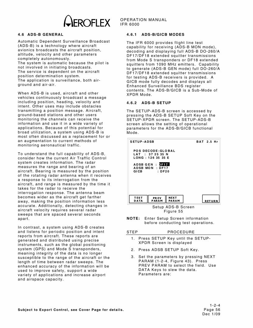
OPERATION MANUAL IFR 6000
1-2-4 Subject to Export Control , see Cover Page for deta i ls . Page 56
Dec 1/09
4.6 ADS-B GENERAL
Automat ic Dependent Surve i l lance Broadcast (ADS-B) is a technology where a i rcraf t av ion ics broadcasts the a i rcraf t pos i t ion, a l t i tude, ve loc i ty and other parameters complete ly autonomously . The system is automat ic because the p i lo t is not invo lved in in i t ia t ing broadcasts . The serv ice is dependent on the a i rcraf t pos i t ion determinat ion system. The appl icat ion is surve i l lance, both a i r -ground and a i r -a i r . When ADS-B is used, a i rcraf t and other vehic les cont inuously broadcast a message inc lud ing pos i t ion, heading, ve loc i ty and in tent . Other uses may inc lude obstac les t ransmi t t ing a pos i t ion message. A i rcraf t , ground-based s tat ions and other users moni tor ing the channels can receive the in format ion and use i t in a wide var ie ty o f appl icat ions. Because of th is potent ia l for broad ut i l izat ion, a system us ing ADS-B is most o f ten d iscussed as a rep lacement for or an augmentat ion to current methods of moni tor ing aeronaut ica l t ra f f ic . To understand the fu l l capabi l i ty o f ADS-B, consider how the current A i r Traf f ic Contro l system creates in format ion. The radar measures the range and bear ing of an a i rcraf t . Bear ing is measured by the pos i t ion of the rotat ing radar antenna when i t rece ives a response to i ts in ter rogat ion f rom the a i rcraf t , and range is measured by the t ime i t takes for the radar to receive the in ter rogat ion response. The antenna beam becomes wider as the a i rcraf t get far ther away, making the pos i t ion in format ion less accurate. Addi t ional ly , detect ing changes in a i rcraf t ve loc i ty requi res severa l radar sweeps that are spaced severa l seconds apar t . In cont rast , a system us ing ADS-B creates and l is tens for per iod ic pos i t ion and in tent repor ts f rom a i rcraf t . These repor ts are generated and d is t r ibuted us ing prec ise inst ruments, such as the g lobal pos i t ion ing system (GPS) and Mode S t ransponders, meaning in tegr i ty o f the data is no longer suscept ib le to the range of the a i rcraf t or the length of t ime between radar sweeps. The enhanced accuracy of the in format ion wi l l be used to improve safety , suppor t a wide var ie ty o f appl icat ions and increase a i rpor t and a i rspace capaci ty .
4.6.1 ADS-B/GICB MODES
The IFR 6000 prov ides f l ight l ine test capabi l i ty for receiv ing (ADS-B MON mode) , decoding and d isp lay ing fu l l ADS-B DO-260/A DF17/DF18 extended squi t ter t ransmiss ions f rom Mode S t ransponders or DF18 extended squi t ters f rom 1090 MHz emi t ters . Capabi l i ty to generate (ADS-B GEN mode) fu l l DO-260/A DF17/DF18 extended squi t ter t ransmiss ions for test ing ADS-B receivers is prov ided. A GICB mode fu l ly decodes and d isp lays a l l Enhanced Survei l lance BDS regis ter contents . The ADS-B/GICB is a Sub-Mode of XPDR Mode.
4.6.2 ADS-B SETUP
The SETUP-ADS-B screen is accessed by press ing the ADS-B SETUP Sof t Key on the SETUP-XPDR screen. The SETUP-ADS-B screen a l lows the set t ing of operat ional parameters for the ADS-B/GICB funct ional Mode.
B A T 2 .5 H r
PO S D EC OD E : GL O B A L L A T : 3 7 2 5 35 N L ON G : 1 2 6 35 35 E A D SB G E N : D F 1 7 A D SB MO N : D F 1 7 GI CB : D F 2 0
T ES TD A TA
PR EVP ARA M
NEX TPA RA M
S ET U P - A D SB
RET URN
Setup ADS-B Screen F igure 55
NOTE: Enter Setup Screen in format ion before conduct ing test operat ions.
STEP PROCEDURE
1. Press SETUP Key unt i l the SETUP-XPDR Screen is d isp layed
2. Press ADSB SETUP Sof t Key.
3 . Set the parameters by press ing NEXT PARAM (1-2-4, F igure 43) . Press PREV PARAM to se lect the f ie ld . Use DATA Keys to s lew the data. Parameters are:

OPERATION MANUAL IFR 6000
1-2-4 Subject to Export Control , see Cover Page for deta i ls . Page 57
Dec 1/09
STEP PROCEDURE
● POS DECODE:
Wi th GLOBAL selected s imulated or decoded Lat i tude and Longi tude wi l l use the Global a lgor i thm. BDS 0,6 requi res a loca l LAT and LONG to resolve CPB posi t ional a lgor i thm ambigui ty .
Wi th LOCAL selected, s imulated or decoded Lat i tude and Longi tude (BDS 0,5 and BDS 0,6) wi l l use the loca l a lgor i thm which requi res a loca l LAT and LONG to be entered to resolve CPR posi t ional a lgor i thm ambigui ty .
● LAT:
Local Lat i tude of UUT in Degrees, Minutes and Seconds, East or West .
● LONG:
Local Longi tude of UUT in Degrees, Minutes and Seconds, Nor th or South.
● ADS-B GEN:
Select Extended squi t ter type that test set wi l l t ransmi t , DF17 or DF18.
● ADS-B MON:
Select Extended squi t ter type that test set wi l l rece ive DF17 or DF18.
● GICB:
Select DF20 or DF21 for GICB BDS t ransfer .
4 . Press the RETURN sof tkey to d isp lay the prev ious screen.
SETUP TEST DATA
The SETUP-ADS-B Screen a l lows storage and recal l o f a l l SETUP-ADS-B test screens, inc lud ing measurement data (1-2-4, F igure 45) . There are s ix s torage memor ies. The f i rs t s torage memory reta ins the last power down data and cannot be overwr i t ten. The last f ive are def ined by the Test Set operator .
1 L a st p o w e r- d o wn 2 A T C 1 0 /5 /0 5 1 2: 4 5 : 13 3 4 00 D 5 F 1 0 /1 0 /0 5 1 3: 4 3: 1 6
4 5 6 7 8 9 10 11 12
B A T 2 .5 H r
ST ORE
DUMP ST ORE
S ET U P – A D S B T E ST D A T A
D UMPLIV E LO A D
S RETUR N
Setup Test Data Screen F igure 56
B A T 2 .5 H r
Y ES
C ON F IR M
Ov er wr i t e e x is t in g s t o re ?
NO
Conf i rm Screen F igure 57
B A T 2 .5 H r
EN TER
BA C K S PA C E
S ET U P – S T OR E N A M E
A B C D E F GH I JK L M N O PQ RS T U V WX YZ
ab c d e f g h ij kl mn o p q rst u vw xy z
0 2 34 5 67 8 89 ! ‘ “ ( ) * , - . / : ; ? @ _
40 0 D5 F 10 / 10 /0 5 1 3: 4 3 : 06
Please enter store name
C HA RS ELEC T
C A NC EL
Setup Store Name Screen F igure 58

OPERATION MANUAL IFR 6000
1-2-4 Subject to Export Control , see Cover Page for deta i ls . Page 58
Dec 1/09
Data Storage Procedure:
STEP PROCEDURE
1. Press SETUP Select Key unt i l SETUP – XPDR Screen is d isp layed. Press ADSB SETUP Sof t Key to d isp lay SETUP ADS-B Screen (1-2-4, F igure 43) .
2 . Press TEST DATA Sof t Key to d isp lay SETUP-ADSB Test Data Screen (1-2-4, F igure 44) .
3 . Use DATA Keys to se lect the requi red s tore. Press STORE Sof t Key to d isp lay CONFIRM Screen (1-2-4, F igure 45) .
4 . Press YES Sof t Key to conf i rm overwr i te . SETUP STORE NAME Screen is d isp layed (1-2-4, F igure 46) . Store name can be b lank.
5 . Use DATA Keys to se lect the character l ine. Use DATA Keys to se lect des i red character .
6 . Press CHAR SELECT Sof t Key to add se lected character to the end of name s t r ing. Press BACK SPACE Sof t Key to de lete the se lected character .
7 . Press ENTER Sof t Key to s tore name and d isp lay SETUP-ADSB TEST DATA Screen.
8 . Press XPDR Mode Key unt i l ADS-B MAIN menu is d isp layed.
Data Recal l Procedure:
1. Press SETUP Select Key unt i l SETUP – XPDR Screen is d isp layed. Press ADSB SETUP Sof t Key to d isp lay SETUP ADS-B Screen (1-2-4, F igure 43) .
2 . Press TEST DATA Sof t Key to d isp lay SETUP-ADSB Test Data Screen (1-2-4, F igure 44) .
3 . Press RECALL Sof t Key to reca l l tes t data. Press XPDR Mode Key unt i l ADSB MAIN menu is d isp layed.
4.6.3 ADS-B/GICB MAIN
Press the XPDR mode key twice to d isp lay the ADS-B/GICB Main Menu (1-2-4 f igure 47) .
B A T 2 .5 H r
A D SBMO N GI CB
A D S- B / GI C B M A IN
A DSBGEN
ADS-B/GICB Main Menu Figure 59
Press the ADS-B MON sof tkey to d isp lay the ADS-B MON l is t screen. Press the GICB sof tkey to d isp lay the GICB l is t screen.
4.6.4 ADS-B MON
The ADS-B MON mode of operat ion receives Transponder DF17 or Ground Emit ter DF18 extended squi t ters , e i ther v ia the Antenna por t or RF I /O por t . The squi t ters are captured in a buf fer , decoded and d isp layed.
B A T 2 .5 H r
1 0, 5 A I RB O R N E PO S - AV A IL 2 0, 6 S U RF A C E PO S - N O T C A P 3 0, 8 I D EN T & C A T - AV A IL 4 0, 9 A I RB O R N E VE L - AV A IL 5 6, 1 A / C S T A T U S - AV A IL 6 6, 2 T A R G ST A T E - AV A IL 7 6, 5 A / C OP S T A T U S - AV A IL 8 0, A T EST M SG - AV A IL
RUNT ES T
B DSDA TA
A D S- B M ON DF 17
RET URN
ADS-B MON Lis t Screen F igure 60

OPERATION MANUAL IFR 6000
1-2-4 Subject to Export Control , see Cover Page for deta i ls . Page 59
Dec 1/09
The ADS-B MON screen d isp lays suppor ted squi t ters that are ident i f ied by BDS regis ter number and an abbrev iated name (1-2-4 f igure 48) . Status of the received squi t ter is d isp layed to the r ight o f the squi t ter name. Ind icat ions are AVAIL (squi t ter has been captured) , NO SQTR (Squi t ter avai lab le but not captured) , NOT CAP ( t ransponder has ident i f ied squi t ter is not suppor ted by t ransponder /subsystem).
TEST SCREEN DESCRIPTIONS
ADS-B MON BDS 0,5
B A T 2 .5 H r
B D S= 0 ,5 A I R B OR N E PO S T YP E= 14 DF 17 A A= 3 A C 42 1 ( 1 6 54 2 04 1 ) C O U N T = 10 0 0 M E= 00 0 00 0 00 0 0 00 00 P ER I OD = D EF AU L T L A T = 3 7 3 9 00 N L O N G= 9 7 2 5 48 W PO S= GL O B A L SA F = 1 T = N /U T C SU R V EI L L A N C E ST A T US = N O IN F O B A RO P R ES A L T = 13 10 2 5 f t GN S S AL T = N/ A
RUN T ES T
PRE V TES T
A D S- B M ON BD S 0 , 5 A V A IL
NEX T TES T
RET URN
ADS-B MON BDS 0,5 Screen F igure 61
DF17/18: Receives extended squi t ter decodes and d isp lays a i rborne pos i t ion
NOTE: ADLP (Ai r Data L ink Processor) must be insta l led or t ransponder must have embedded ADLP, to receive data f rom subsystem.
NOTE: Insta l la t ion must be in the a i rborne s tate to t ransmi t a i rborne pos i t ion.
AA (Ai rcraf t Address) in HEX and (OCTAL) COUNT Ind icat ions: Disp lays to ta l squi t ters received s ince test was run, range 0 to 9999.
ME message f ie ld d isp layed in 14 d ig i t HEX format .
PERIOD Ind icat ions: Disp lays DF17/18 squi t ter per iod in seconds.
LAT (Encoded la t i tude) and LONG (Encoded longi tude) decoded CPR format in degrees, minutes and seconds.
BARO PRESS ALT (Barometr ic Pressure Al t i tude) Ind icat ions: N/A Disp layed for types 9 to 18, range –1000 to 126700 f t . GNSS ALTITUDE. Ind icat ions: N/A Disp layed for types 20 to 22, RANGE -1000 TO 126700 f t .
POS (Posi t ion Decode) Ind icat ions: GLOBAL ( i f Global LAT/LONG not entered in ADS-B/GICB setup menu). LOCAL ( i f Local LAT/LONG is entered in ADS-B/GICB setup menu).
SURVEILLANCE STATUS Ind icat ions: NO INFO (No Informat ion) , SPI (Specia l Posi t ion Ident i f icat ion) , PERM ALERT (Permanent Aler t (Emergency) , TEMP ALERT (Temporary Aler t (change in Mode ident i ty code) .
SAF (Single Antenna Flag) Ind icat ions: 0 (s ing le antenna) , 1 (dual antenna) .
T (T ime Sync to UTC) Ind icat ions: N/UTC (not UTC), UTC.
TYPE Speci f ies c lass and accuracy of data. Refer to tab le A-2 RTCA DO-260A V2.
NOTE : Refer to ICAO Annex 10, Vol l I I , Par t 1 , Chapter 5 and RTCA-DO-260 for deta i led descr ip t ion of data f ie lds
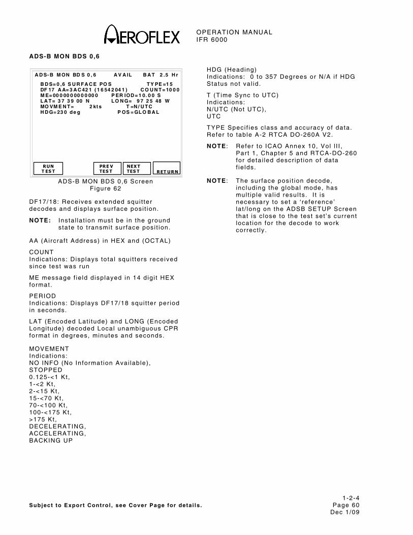
OPERATION MANUAL IFR 6000
1-2-4 Subject to Export Control , see Cover Page for deta i ls . Page 60
Dec 1/09
ADS-B MON BDS 0,6
B A T 2 .5 H r
B D S= 0 ,6 S U R F A C E PO S T Y PE =1 5 DF 17 A A= 3 A C 42 1 ( 1 6 54 2 04 1 ) C O U N T = 10 0 0 M E= 00 0 00 0 00 0 0 00 0 P ER IOD = 1 0. 0 0 S L A T = 3 7 3 9 00 N L O N G= 9 7 2 5 48 W MO VM E N T = 2 kt s T =N / U T C H D G= 23 0 d e g P OS = GL O B A L
RUN T ES T
PRE V TES T
A D S- B M ON BD S 0 , 6 A V A IL
NEX T TES T
RET URN
ADS-B MON BDS 0,6 Screen F igure 62
DF17/18: Receives extended squi t ter decodes and d isp lays sur face pos i t ion.
NOTE: Insta l la t ion must be in the ground s tate to t ransmi t sur face pos i t ion.
AA (Ai rcraf t Address) in HEX and (OCTAL)
COUNT Ind icat ions: Disp lays to ta l squi t ters received s ince test was run
ME message f ie ld d isp layed in 14 d ig i t HEX format .
PERIOD Ind icat ions: Disp lays DF17/18 squi t ter per iod in seconds.
LAT (Encoded Lat i tude) and LONG (Encoded Longi tude) decoded Local unambiguous CPR format in degrees, minutes and seconds.
MOVEMENT Ind icat ions: NO INFO (No Informat ion Avai lab le) , STOPPED 0.125-<1 Kt , 1-<2 Kt , 2-<15 Kt , 15-<70 Kt , 70-<100 Kt , 100-<175 Kt , >175 Kt , DECELERATING, ACCELERATING, BACKING UP
HDG (Heading) Ind icat ions: 0 to 357 Degrees or N/A i f HDG Status not va l id .
T (T ime Sync to UTC) Ind icat ions: N/UTC (Not UTC), UTC
TYPE Speci f ies c lass and accuracy of data. Refer to tab le A-2 RTCA DO-260A V2.
NOTE : Refer to ICAO Annex 10, Vol l I I , Par t 1 , Chapter 5 and RTCA-DO-260 for deta i led descr ip t ion of data f ie lds.
NOTE : The sur face pos i t ion decode, inc lud ing the g lobal mode, has mul t ip le va l id resul ts . I t is necessary to set a ‘ re ference’ la t / long on the ADSB SETUP Screen that is c lose to the test set ’s current locat ion for the decode to work correct ly .

OPERATION MANUAL IFR 6000
1-2-4 Subject to Export Control , see Cover Page for deta i ls . Page 61
Dec 1/09
ADS-B MON BDS 0,8
B A T 2 .5 H r
B D S= 0 ,8 I D EN T & C A T T YP E= 2 DF 17 A A= 3 A C 42 1 ( 1 6 54 2 04 1 ) C O U N T = 10 0 0 M E= 00 0 00 0 00 0 0 00 00 P ER I OD = 10 . 00 S A IS = 2 04 2 0C C B 9 C 10 F L IG H T I D = XP N3 4 5 12 EM IT C A T SE T = A EM IT C A T = L A R GE
RUN T ES T
PRE V TES T
A D S- B M ON BD S 0 , 8 A VA I L
NEX T TES T
RET URN
ADS-B MON BDS 0,8 Screen F igure 63
DF17,18: Receives extended squi t ter decodes and d isp lays ident i f icat ion and category.
NOTE: ADLP (Ai r Data L ink Processor) must be insta l led or t ransponder must have embedded ADLP, to receive data f rom subsystem.
AA (Ai rcraf t Address) in HEX and (OCTAL)
COUNT Ind icat ions: Disp lays to ta l squi t ters received s ince test was run.
ME message f ie ld d isp layed in 14 d ig i t HEX format .
PERIOD Ind icat ions: Disp lays DF17/18 squi t ter per iod in seconds.
EMIT CAT SET (ADS-B Emit ter Category Set) . Ind icat ions: D,C,B,A.
EMIT CAT (ADS-B Emit ter Category) . Ind icat ions: SMALL, MEDIUM or LARGE
EMIT CAT A:
NO ADS-B EMITTER INFO, LIGHT, SMALL, LARGE, HIGH VORTEX, HEAVY, HIGH PERFORMANCE, ROTOCRAFT,
EMIT CAT B:
NO ADS-B EMITTER INFO, GLIDER/SAILPLANE, LIGHTER-THAN-AIR, PARACHUTIST/SKYDIVER, ULTRALIGHT/HANG-GLIDER, RESERVED, UNMANNED AERIAL VEHICLE, SPACE VEHICLE.
EMIT CAT C: NO ADS-B EMITTER INFO, SURFACE EMERGENCY VEHICLE, SURFACE SERVICE VEHICLE, FIXED GND/TETHERED OBSTR, CLUSTER OBSTR, LINE OBSTR, RESERVED, RESERVED
EMIT CAT D:
RESERVED, RESERVED, RESERVED, RESERVED, RESERVED, RESERVED, RESERVED
AIS (Ai rcraf t Ident i ty Subf ie ld) HEX f ie ld conta in ing BDS p lus f l ight ID.
FLIGHT ID Ind icat ions: 8 ICAO character f ie ld .
TYPE Speci f ies c lass and accuracy of data. Refer to tab le A-2 RTCA DO-260A V2.
NOTE : Refer to ICAO Annex 10, Vol l I I , Par t 1 , Chapter 5 and RTCA-DO-260 for deta i led descr ip t ion of data f ie lds.
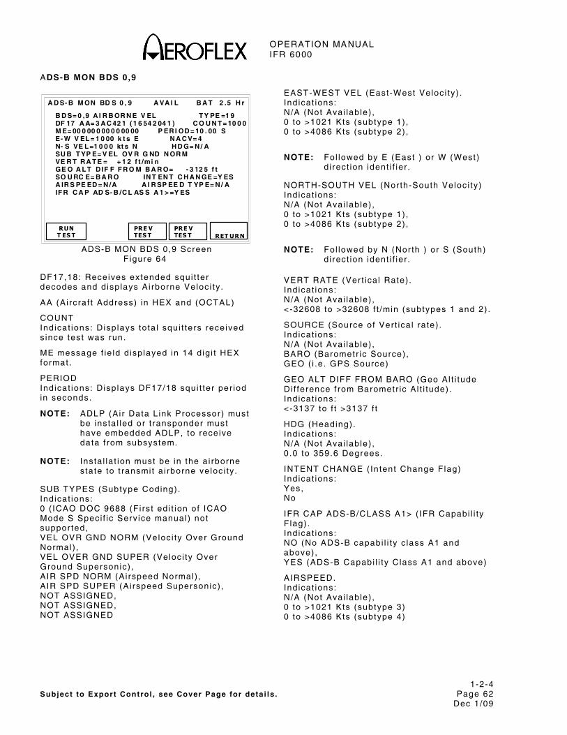
OPERATION MANUAL IFR 6000
1-2-4 Subject to Export Control , see Cover Page for deta i ls . Page 62
Dec 1/09
ADS-B MON BDS 0,9
B A T 2 .5 H r
B D S= 0 ,9 A I R B OR N E V EL T Y PE =1 9 DF 17 A A= 3 A C 42 1 ( 1 6 54 2 04 1 ) C O U N T = 10 0 0 M E= 00 0 00 0 00 0 0 00 00 P ER I OD = 10 . 00 S E- W V EL = 1 0 00 k t s E N A C V= 4 N- S VE L =1 0 0 0 kt s N H D G= N / A SU B T YP E= V EL OV R G ND N OR M VE R T R A T E = + 1 2 f t /mi n GE O A L T D IF F F R O M B A R O= - 3 12 5 f t SO U RC E= B A R O IN T EN T C H A N GE =Y ES A IR S PE ED = N /A A I R SP EE D T YP E= N / A IF R C A P AD S- B /C L AS S A 1 > =Y ES
RUN T ES T
PRE V TES T
A D S- B M ON BD S 0 , 9 A VA I L
PRE V TES T
RET URN
ADS-B MON BDS 0,9 Screen F igure 64
DF17,18: Receives extended squi t ter decodes and d isp lays Ai rborne Veloc i ty .
AA (Ai rcraf t Address) in HEX and (OCTAL)
COUNT Ind icat ions: Disp lays to ta l squi t ters received s ince test was run.
ME message f ie ld d isp layed in 14 d ig i t HEX format .
PERIOD Ind icat ions: Disp lays DF17/18 squi t ter per iod in seconds.
NOTE: ADLP (Ai r Data L ink Processor) must be insta l led or t ransponder must have embedded ADLP, to receive data f rom subsystem.
NOTE: Insta l la t ion must be in the a i rborne s tate to t ransmi t a i rborne ve loc i ty .
SUB TYPES (Subtype Coding) . Ind icat ions: 0 ( ICAO DOC 9688 (F i rs t ed i t ion of ICAO Mode S Speci f ic Serv ice manual ) not suppor ted, VEL OVR GND NORM (Veloc i ty Over Ground Normal) , VEL OVER GND SUPER (Veloc i ty Over Ground Supersonic) , AIR SPD NORM (Ai rspeed Normal) , AIR SPD SUPER (Ai rspeed Supersonic) , NOT ASSIGNED, NOT ASSIGNED, NOT ASSIGNED
EAST-WEST VEL (East-West Veloc i ty ) . Ind icat ions: N/A (Not Avai lab le) , 0 to >1021 Kts (subtype 1) , 0 to >4086 Kts (subtype 2) ,
NOTE: Fol lowed by E (East ) or W (West) d i rect ion ident i f ier .
NORTH-SOUTH VEL (North-South Veloc i ty ) Ind icat ions: N/A (Not Avai lab le) , 0 to >1021 Kts (subtype 1) , 0 to >4086 Kts (subtype 2) ,
NOTE: Fol lowed by N (Nor th ) or S (South) d i rect ion ident i f ier .
VERT RATE (Ver t ica l Rate) . Ind icat ions: N/A (Not Avai lab le) , <-32608 to >32608 f t /min (subtypes 1 and 2) .
SOURCE (Source of Ver t ica l ra te) . Ind icat ions: N/A (Not Avai lab le) , BARO (Barometr ic Source) , GEO ( i .e . GPS Source)
GEO ALT DIFF FROM BARO (Geo Al t i tude Di f ference f rom Barometr ic A l t i tude) . Ind icat ions: <-3137 to f t >3137 f t
HDG (Heading) . Ind icat ions: N/A (Not Avai lab le) , 0 .0 to 359.6 Degrees.
INTENT CHANGE ( Intent Change Flag) Ind icat ions: Yes, No
IFR CAP ADS-B/CLASS A1> ( IFR Capabi l i ty F lag) . Ind icat ions: NO (No ADS-B capabi l i ty c lass A1 and above) , YES (ADS-B Capabi l i ty Class A1 and above)
AIRSPEED. Ind icat ions: N/A (Not Avai lab le) , 0 to >1021 Kts (subtype 3) 0 to >4086 Kts (subtype 4)
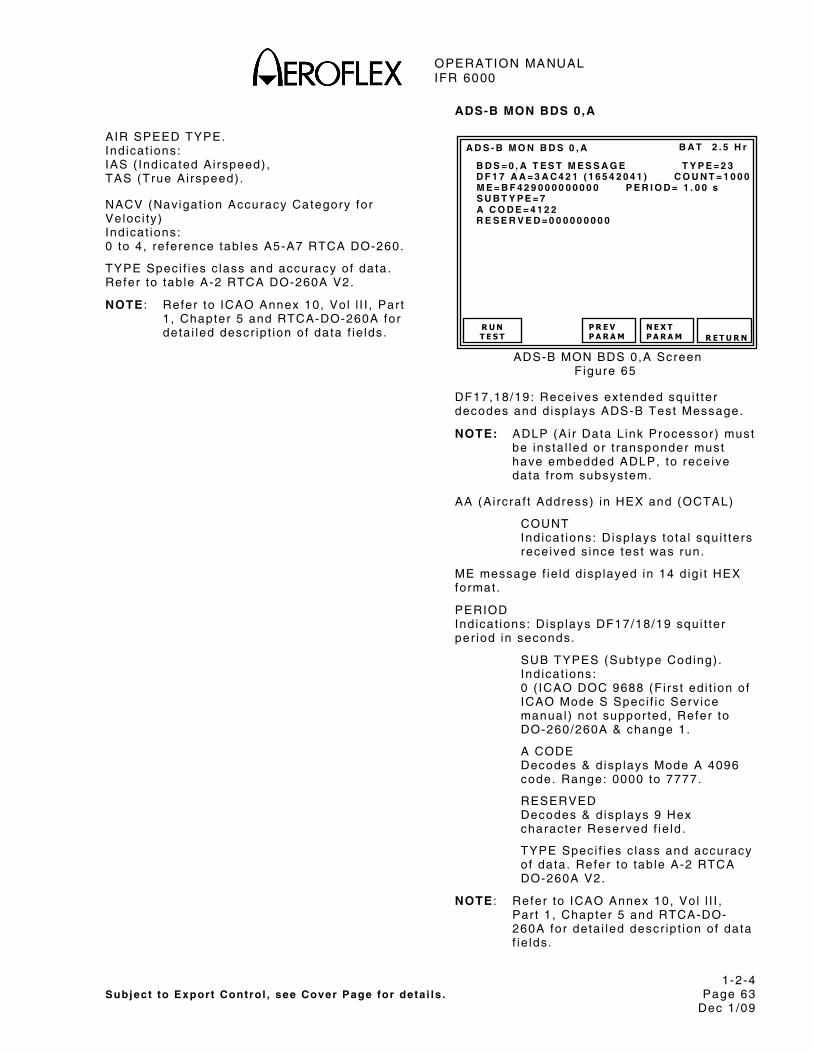
OPERATION MANUAL IFR 6000
1-2-4 Subject to Export Control , see Cover Page for deta i ls . Page 63
Dec 1/09
AIR SPEED TYPE. Ind icat ions: IAS ( Ind icated Ai rspeed) , TAS (True Ai rspeed) .
NACV (Navigat ion Accuracy Category for Veloc i ty ) Ind icat ions: 0 to 4, re ference tab les A5-A7 RTCA DO-260.
TYPE Speci f ies c lass and accuracy of data. Refer to tab le A-2 RTCA DO-260A V2.
NOTE : Refer to ICAO Annex 10, Vol l I I , Par t 1 , Chapter 5 and RTCA-DO-260A for deta i led descr ip t ion of data f ie lds.
ADS-B MON BDS 0,A
B A T 2 . 5 H r
B D S = 0 , A T E S T M E S S A G E T Y P E = 2 3 D F 1 7 A A = 3 A C 4 2 1 ( 1 6 5 4 2 0 4 1 ) C O U N T = 1 0 0 0 M E = B F 4 2 9 0 0 0 0 0 0 0 0 0 P E R I O D = 1 . 0 0 s S U B T Y P E = 7 A C O D E = 4 1 2 2 R E S E R V E D = 0 0 0 0 0 0 0 0 0
R U NT E S T
P R E VP A R A M
A D S - B M O N B D S 0 , A
N E X TP A R A M R E T U R N
ADS-B MON BDS 0,A Screen F igure 65
DF17,18/19: Receives extended squi t ter decodes and d isp lays ADS-B Test Message.
NOTE: ADLP (Ai r Data L ink Processor) must be insta l led or t ransponder must have embedded ADLP, to receive data f rom subsystem.
AA (Ai rcraf t Address) in HEX and (OCTAL)
COUNT Ind icat ions: Disp lays to ta l squi t ters received s ince test was run.
ME message f ie ld d isp layed in 14 d ig i t HEX format .
PERIOD Ind icat ions: Disp lays DF17/18/19 squi t ter per iod in seconds.
SUB TYPES (Subtype Coding) . Ind icat ions: 0 ( ICAO DOC 9688 (F i rs t ed i t ion of ICAO Mode S Speci f ic Serv ice manual ) not suppor ted, Refer to DO-260/260A & change 1.
A CODE Decodes & d isp lays Mode A 4096 code. Range: 0000 to 7777.
RESERVED Decodes & d isp lays 9 Hex character Reserved f ie ld .
TYPE Speci f ies c lass and accuracy of data. Refer to tab le A-2 RTCA DO-260A V2.
NOTE : Refer to ICAO Annex 10, Vol l I I , Par t 1 , Chapter 5 and RTCA-DO-260A for deta i led descr ip t ion of data f ie lds.

OPERATION MANUAL IFR 6000
1-2-4 Subject to Export Control , see Cover Page for deta i ls . Page 64
Dec 1/09
ADS-B MON BDS 6,1
B A T 2 .5 H r
B D S= 6 ,1 A / C S T A T U S T YP E= 2 8 DF 17 A A= 3 A C 42 1 ( 1 6 54 2 04 1 ) C O U N T = 10 0 0 M E= 00 0 00 0 00 0 0 00 00 P ER I OD = 10 . 00 S EM E RG /P R IO R C O D E= U N L A W F U L IN T ER F N C R ES ER V ED = 0 00 0 00 0 00 0 00 0 0 SU B T Y PE = EM E RG EN C Y /P R IO R IT Y S T A T U S
RUN T ES T
PRE V TES T
A D S- B M ON BD S 6 , 1 A V A IL
PRE V TES T
RET URN
ADS-B MON BDS 6,1 Screen F igure 66
DF17,18: Receives extended squi t ter decodes and d isp lays Ai rcraf t Status.
AA (Ai rcraf t Address) in HEX and (OCTAL)
COUNT Ind icat ions: Disp lays to ta l squi t ters received s ince test was run.
ME message f ie ld d isp layed in 14 d ig i t HEX format .
PERIOD Ind icat ions: Disp lays DF17/18 squi t ter per iod in seconds.
NOTE: ADLP (Ai r Data L ink Processor) must be insta l led or t ransponder must have embedded ADLP, to receive data f rom subsystem.
SUB TYPE (Subtype Coding) . Ind icat ions: NO INFO, EMERGENCY/PRIORITY STATUS, RESERVED
EMERG/PRIOR CODE (Emergency/Pr ior i ty Status Coding) . Ind icat ions: NO EMERGENCY, GENERAL EMERGENCY, LIFEGUARD/MEDICAL, MINIMUM FUEL, NO COMM, UNLAWFUL INTERFNC, DOWNED AIRCRAFT, RESERVED.
RESERVED subf ie ld , 12 d ig i t HEX f ie ld conta in ing contents of b i ts 9 to 56. TYPE Speci f ies c lass and accuracy of data. Refer to tab le A-2 DO-260A V2.ADS-B MON BDS 6,2
B A T 2 .5 H r
B D S= 6 ,2 T A R G S T A T E T Y PE = 29 DF 17 A A= 3 A C 42 1 ( 1 6 54 2 04 1 ) C O U N T = 10 0 0 M E= 00 0 00 0 00 0 0 00 00 P ER I OD = 10 . 00 S VE R T D A T A / SO U R C E IN F O =F MS /N A V T A R G AL T C A P =H L D G AL T - A C P- F M S/ R N A V VE R T M OD E I N D = A C QU IR IN G S IL = 1 T A R G AL T T Y PE = M SL N IC B AR O = 1 T A R G AL T = 3 10 0 0 f t T A R G H D G = 24 0 d e g T C A S/ A C AS OPE R A T I ON A L = Y ES R A A = N O H OR IZ D A T A AV A IL /S OU R C E IN D = M C P/ F C U H OR IZ M OD E I N D = M AI N T A IN I N G N A C = 0 EM E RG /P R IO R C O D E= U N L A W F U L IN T ER F N C
RUNT ES T
PRE VTES T
A D S- B M ON BD S 6 , 2 A V A IL
PRE V TES T
RET URN
ADS-B MON BDS 6,2 Screen F igure 67
DF17,18: Receives extended squi t ter decodes and d isp lays Target State.
AA (Ai rcraf t Address) in HEX and (OCTAL)
COUNT Ind icat ions: Disp lays to ta l squi t ters received s ince test was run.
ME message f ie ld d isp layed in 14 d ig i t HEX format .
PERIOD Ind icat ions: Disp lays DF17/18 squi t ter in seconds.
NOTE: ADLP (Ai r Data L ink Processor) must be insta l led or t ransponder must have embedded ADLP, to receive data f rom subsystem.
NOTE Insta l la t ion must be in the a i rborne s tate to t ransmi t target s ta te and s tatus.
NOTE: Autopi lo t must be engaged and s t imulated by sensor data for some f ie lds to d isp lay data.
SUBTYPE= 0
VERT DATA/SOURCE INFO (Vert ica l Data Avai lab le/Source Ind icator) Ind icat ions: MCP/FCU (Mode Contro l Panel /F l ight Contro l Uni t ) , HLD ALT (Hold ing Al t i tude) , FMS/RNAV (FMS/RNAV System).

OPERATION MANUAL IFR 6000
1-2-4 Subject to Export Control , see Cover Page for deta i ls . Page 65
Dec 1/09
VERT MODE IND (Ver t ica l Mode Ind icator) Ind icat ions: UNKNOWN, (Unknown Mode or In format ion unavai lab le) , ACQUIRING (Acqui r ing Mode) , MAINTAINING (Captur ing or Mainta in ing Mode) . RESERVED
TARGET ALT CAP (Target Al t i tude Capabi l i ty ) Ind icat ions: HLDG ALT (Capabi l i ty for repor t ing Hold ing a l t i tude only) , HLDG ALT-ACP (Capabi l i ty for repor t ing e i ther Hold ing a l t i tude or Autopi lo t cont ro l panel se lected a l t i tude) , HLDG ALT-ACP-FMS/RNAV (Capabi l i ty for repor t ing e i ther Hold ing a l t i tude or Autopi lo t cont ro l panel se lected a l t i tude, or any FMS/RNAV level o f f a l t i tude) . RESERVED
H DATA AVAIL/SOURCE IND (Hor izonta l Data Avai lab le/Source Ind icator) Ind icat ions: NOT VALID (No Val id Hor izonta l Target State Data is avai lab le) , MCP/FCU (Mode Contro l Panel /F l ight Contro l Uni t se lected t rack angle) , MAINTAIN (Mainta in Current Heading or Track angle) , FMS/RNAV (FMS/RNAV System)
TARGET HDG (Target Heading Angle) Ind icat ions: 0 to 359 degrees. INVALID
HORIZ MODE IND (Hor izonta l Mode Ind icator) Ind icat ions: UNKNOWN (Unknown Mode or In format ion unavai lab le) , ACQUIRING (Acqui r ing Mode) , MAINTAINING (Captur ing or Mainta in ing Mode) , RESERVED.
NIC BARO (Navigat ion In tegr i ty Baro) Ind icat ions: 0 (Gi l lum Cross Checked) 1 (Gi l lum Not Cross Checked)
SIL (Surve i l lance In tegr i ty Level ) Ind icat ions: 0 (Unknown), 1 (1x10(-3) per f l ight ) , 2 (1x10(-5) per f l ight ) , 3 (1x10(-7) per f l ight )
TCAS/ACAS OPERATIONAL (TCAS/ACAS Operat ional ) Ind icat ions: YES, NO.
RAA (TCAS/ACAS Resolut ion Adv isory Act ive) Ind icat ions: YES, NO.
TYPE Speci f ies c lass and accuracy of data. Refer to tab le A-2 RTCA DO-260A V2.
NOTE: Refer to ICAO Annex 10 Vol l I I Chapter 5 and RTCA-DO-260A for deta i led descr ip t ion of data f ie lds.
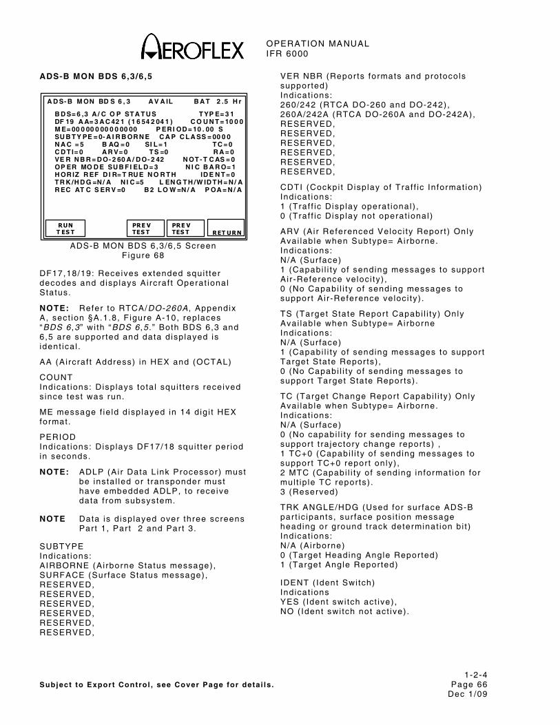
OPERATION MANUAL IFR 6000
1-2-4 Subject to Export Control , see Cover Page for deta i ls . Page 66
Dec 1/09
ADS-B MON BDS 6,3/6,5
B A T 2 .5 H r
B D S= 6 ,3 A / C O P ST A T U S T YP E= 3 1 DF 19 A A= 3 A C 42 1 ( 1 6 54 2 04 1 ) C O U N T = 10 0 0 M E= 00 0 00 0 00 0 0 00 00 P ER I OD = 10 . 00 S SU B T Y PE = 0- A I R B OR N E C A P C L A SS = 00 0 0 N A C = 5 B AQ = 0 SI L = 1 T C = 0 C D T I= 0 A R V= 0 T S =0 R A = 0 VE R N B R = D O- 2 60 A / D O- 2 42 N OT - T C AS = 0 OP ER MO D E SU B F I EL D = 3 N I C B A R O= 1 H OR IZ R EF D I R= T RU E N O R T H ID E N T = 0 T R K /H D G =N / A N I C =5 L EN G T H /W ID T H = N / A R EC AT C S ER V =0 B 2 L O W =N / A P OA = N / A
RUN T ES T
PRE V TES T
A D S- B M ON BD S 6 , 3 A V A IL
PRE V TES T
RET URN
ADS-B MON BDS 6,3/6,5 Screen F igure 68
DF17,18/19: Receives extended squi t ter decodes and d isp lays Ai rcraf t Operat ional Status.
NOTE: Refer to RTCA/DO-260A , Appendix A, sect ion §A.1.8, F igure A-10, rep laces “BDS 6 ,3 ” wi th “BDS 6 ,5 . ” Both BDS 6,3 and 6,5 are suppor ted and data d isp layed is ident ica l .
AA (Ai rcraf t Address) in HEX and (OCTAL)
COUNT Ind icat ions: Disp lays to ta l squi t ters received s ince test was run.
ME message f ie ld d isp layed in 14 d ig i t HEX format .
PERIOD Ind icat ions: Disp lays DF17/18 squi t ter per iod in seconds.
NOTE: ADLP (Ai r Data L ink Processor) must be insta l led or t ransponder must have embedded ADLP, to receive data f rom subsystem.
NOTE Data is d isp layed over three screens Par t 1 , Par t 2 and Par t 3 .
SUBTYPE Ind icat ions: AIRBORNE (Ai rborne Status message) , SURFACE (Sur face Status message) , RESERVED, RESERVED, RESERVED, RESERVED, RESERVED, RESERVED,
VER NBR (Repor ts formats and protocols suppor ted) Ind icat ions: 260/242 (RTCA DO-260 and DO-242) , 260A/242A (RTCA DO-260A and DO-242A), RESERVED, RESERVED, RESERVED, RESERVED, RESERVED, RESERVED,
CDTI (Cockpi t Disp lay of Traf f ic In format ion) Ind icat ions: 1 (Traf f ic Disp lay operat ional ) , 0 (Traf f ic Disp lay not operat ional )
ARV (Ai r Referenced Veloc i ty Repor t ) Only Avai lab le when Subtype= Ai rborne. Ind icat ions: N/A (Sur face) 1 (Capabi l i ty o f sending messages to suppor t A i r -Reference ve loc i ty) , 0 (No Capabi l i ty o f sending messages to suppor t A i r -Reference ve loc i ty) .
TS (Target State Repor t Capabi l i ty ) Only Avai lab le when Subtype= Ai rborne Ind icat ions: N/A (Sur face) 1 (Capabi l i ty o f sending messages to suppor t Target State Repor ts) , 0 (No Capabi l i ty o f sending messages to suppor t Target State Repor ts) .
TC (Target Change Repor t Capabi l i ty ) Only Avai lab le when Subtype= Ai rborne. Ind icat ions: N/A (Sur face) 0 (No capabi l i ty for sending messages to suppor t t ra jectory change repor ts) , 1 TC+0 (Capabi l i ty o f sending messages to suppor t TC+0 repor t on ly) , 2 MTC (Capabi l i ty o f sending in format ion for mul t ip le TC repor ts) . 3 (Reserved)
TRK ANGLE/HDG (Used for sur face ADS-B par t ic ipants , sur face pos i t ion message heading or ground t rack determinat ion b i t ) Ind icat ions: N/A (Ai rborne) 0 (Target Heading Angle Repor ted) 1 (Target Angle Repor ted)
IDENT ( Ident Swi tch) Ind icat ions YES ( Ident swi tch act ive) , NO ( Ident swi tch not act ive) .

OPERATION MANUAL IFR 6000
1-2-4 Subject to Export Control , see Cover Page for deta i ls . Page 67
Dec 1/09
REC ATC SER (Receiv ing ATC Serv ices) Ind icat ions: 1 (A i rcraf t receiv ing ATC serv ices) , 0 (A i rcraf t not receiv ing ATC serv ices) .
A/V LENGTH (Ai rcraf t or Vehic le Length) Ind icat ions: N/A (Ai rborne) <15m, <25m, <35m, <45m, <55m, <65m, <75m, <=200m.
A/V WIDTH (Ai rcraf t or Vehic le Width) Ind icat ions: N/A (Ai rborne) <11.5m, <23m, <28.5m, <34m, <33m, <38m, <39.5m, <45m, <52m, <59.5m, <67m, <72m, <80m, =>80m.
SIL (Surve i l lance In tegr i ty Level ) Ind icat ions: 0 (Unknown), 1 (1x10(-3) per f l ight ) , 2 (1x10(-5) per f l ight ) , 3 (1x10(-7) per f l ight )
NIC BARO (Navigat ion In tegr i ty Baro) Ind icat ions: N/A (Sur face) 0 (Gi l lum Cross Checked) 1 (Gi l lum Not Cross Checked)
NAC Ind icat ions: 0 (EPU >18.52 km) 1 (EPU <18.52 km) 2 (EPU <7.408 km) 3 (EPU <3.704 km) 4 (EPU <1852 m) 5 (EPU <926 m) 6 (EPU <555.6 m) 7 (EPU <185.2 m) 8 (EPU <92.6 m) 9 (EPU <30 m and VEPU <45 m) A (EPU <30 m and VEPU <15 m) B (EPU <3 m and VEPU <4 m) C ( reserved) D ( reserved) E ( reserved) F ( reserved)
BAQ Ind icat ions: N/A (Sur face) 0 (a lways 0 for a i rborne message) 1 (not spec i f ied) 2 (not spec i f ied) 3 (not spec i f ied)
NOT TCAS Ind icat ions: N/A (Sur face) 0 (TCAS operat ions or unknown) 1 (TCAS not insta l led or not operat ional )
OPER MODE Subf ie ld Ind icat ions: 0 (TCAS RA Act ive, IDENT Swi tch Act ive, Receiv ing ATC Serv ices) 1 (Reserved) 2 (Reserved) 3 (Reserved)
NIC Ind icat ions: 0 (Rc unknown) 1 (Rc < 20 NM)
B2 LOW Indicat ions: N/A (Ai rborne) 0 (>70 W) 1 (<70 W)
POA Ind icat ions: N/A (Ai rborne) 0 (Posi t ion t ransmi t ted is not the ADS-B posi t ion reference point ) 1 (Posi t ion t ransmi t ted is the ADS-B posi t ion reference point )
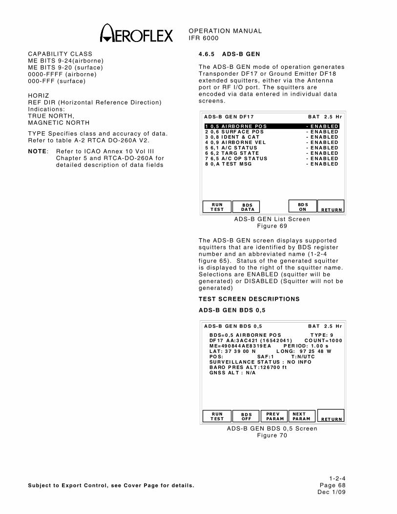
OPERATION MANUAL IFR 6000
1-2-4 Subject to Export Control , see Cover Page for deta i ls . Page 68
Dec 1/09
CAPABILITY CLASS ME BITS 9-24(a i rborne) ME BITS 9-20 (sur face) 0000-FFFF (a i rborne) 000-FFF (sur face)
HORIZ REF DIR (Hor izonta l Reference Di rect ion) Ind icat ions: TRUE NORTH, MAGNETIC NORTH
TYPE Speci f ies c lass and accuracy of data. Refer to tab le A-2 RTCA DO-260A V2.
NOTE : Refer to ICAO Annex 10 Vol l I I Chapter 5 and RTCA-DO-260A for deta i led descr ip t ion of data f ie lds
4.6.5 ADS-B GEN
The ADS-B GEN mode of operat ion generates Transponder DF17 or Ground Emit ter DF18 extended squi t ters , e i ther v ia the Antenna por t or RF I /O por t . The squi t ters are encoded v ia data entered in ind iv idual data screens.
B A T 2 .5 H r
1 0, 5 A I RB O R N E PO S - E N A B L ED 2 0, 6 S U RF A C E PO S - E N A B L ED 3 0, 8 I D EN T & C A T - E N A B L ED 4 0, 9 A I RB O R N E VE L - E N A B L ED 5 6, 1 A / C S T A T U S - E N A B L ED 6 6, 2 T A R G ST A T E - E N A B L ED 7 6, 5 A / C OP S T A T U S - E N A B L ED 8 0, A T EST M SG - E N A B L ED
RUNT ES T
B DSDA TA
A D S- B GE N D F 1 7
RET URN
BD S ON
ADS-B GEN Lis t Screen F igure 69
The ADS-B GEN screen d isp lays suppor ted squi t ters that are ident i f ied by BDS regis ter number and an abbrev iated name (1-2-4 f igure 65) . Status of the generated squi t ter is d isp layed to the r ight o f the squi t ter name. Select ions are ENABLED (squi t ter wi l l be generated) or DISABLED (Squi t ter wi l l not be generated)
TEST SCREEN DESCRIPTIONS
ADS-B GEN BDS 0,5
B A T 2 .5 H r
B D S= 0 ,5 A I R B OR N E PO S T YP E: 9 DF 17 A A: 3 A C 4 21 ( 1 6 54 2 04 1 ) C O U N T = 10 0 0 M E= 49 0 84 4 A E8 3 19 E A P ER IOD : 1. 0 0 s L A T : 3 7 3 9 00 N L ON G: 9 7 25 48 W PO S: SA F : 1 T : N /U T C SU R V EI L L A N C E ST A T US : N O IN F O B A RO P R ES A L T : 12 6 70 0 f t GN S S AL T : N /A
RUNT ES T
B D SOF F
PRE V PA RA M
A D S- B GE N B D S 0 ,5
NEX T PA RA M
RET URN
ADS-B GEN BDS 0,5 Screen F igure 70

OPERATION MANUAL IFR 6000
1-2-4 Subject to Export Control , see Cover Page for deta i ls . Page 69
Dec 1/09
DF17/18: Encodes Ai rborne Posi t ion and generates extended squi t ter .
AA (Ai rcraf t Address) in HEX.
COUNT Ind icat ions: Disp lays to ta l squi t ters generated s ince test was run. Range 0 to 9999.
ME message f ie ld d isp layed in 14 d ig i t HEX format .
PERIOD Select ion: DF17/18 squi t ter per iod in seconds. Range: 0 .5 to 20.00 seconds wi th 0 .2 sec d is t r ibut ion.
LAT (Encoded la t i tude) and LONG (Encoded longi tude) CPR format in degrees, minutes and seconds.
BARO PRESS ALT (Barometr ic Pressure Al t i tude) Select ion: - NA (Not avai lab le) Selectable for types 9 to 18, range –1000 to 126700 f t in 25f t increments. GNSS ALTITUDE. Select ion: - NA (Not avai lab le) Selectable for types 20 to 22, RANGE -1000 to 126700 f t in 25f t increments.
POS (Posi t ion Decode)
SURVEILLANCE STATUS Select ions: NO INFO (No Informat ion) , SPI (Specia l Posi t ion Ident i f icat ion) , PERM ALERT (Permanent Aler t (Emergency) , TEMP ALERT (Temporary Aler t (change in Mode ident i ty code) .
SAF (Single Antenna Flag) Select ions: 0 (s ing le antenna) , 1 (dual antenna) .
T (T ime Sync to UTC) Select ions: N/UTC (not UTC), UTC.
TYPE Speci f ies c lass and accuracy of data. Refer to tab le A-2 RTCA DO-260A V2.
NOTE : Refer to ICAO Annex 10, Vol l I I , Par t 1 , Chapter 5 and RTCA-DO-260A for deta i led descr ip t ion of data f ie lds
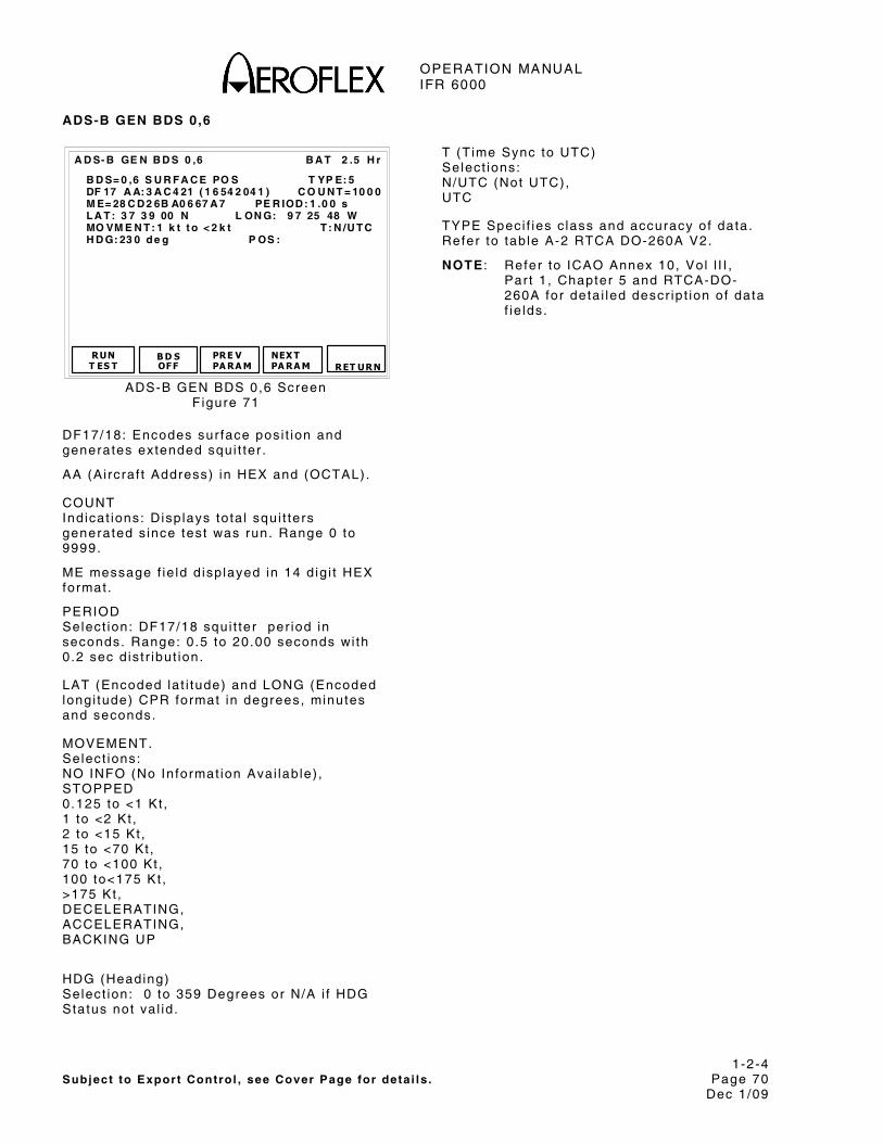
OPERATION MANUAL IFR 6000
1-2-4 Subject to Export Control , see Cover Page for deta i ls . Page 70
Dec 1/09
ADS-B GEN BDS 0,6
B A T 2 .5 H r
B D S= 0 ,6 S U R F A C E PO S T YP E: 5 DF 17 A A: 3 A C 4 21 ( 1 6 54 2 04 1 ) C O U N T = 10 0 0 M E= 28 C D 2 6B A0 6 67 A 7 PE R IOD : 1 .0 0 s L A T : 3 7 3 9 00 N L ON G: 9 7 25 48 W MO VM E N T : 1 k t t o < 2 k t T : N /U T C H D G: 23 0 d e g P OS :
RUN T ES T
B D S OF F
PRE V PA RA M
A D S- B GE N B D S 0 ,6
NEX T PA RA M
RET URN
ADS-B GEN BDS 0,6 Screen F igure 71
DF17/18: Encodes sur face pos i t ion and generates extended squi t ter .
AA (Ai rcraf t Address) in HEX and (OCTAL).
COUNT Ind icat ions: Disp lays to ta l squi t ters generated s ince test was run. Range 0 to 9999.
ME message f ie ld d isp layed in 14 d ig i t HEX format .
PERIOD Select ion: DF17/18 squi t ter per iod in seconds. Range: 0 .5 to 20.00 seconds wi th 0 .2 sec d is t r ibut ion.
LAT (Encoded la t i tude) and LONG (Encoded longi tude) CPR format in degrees, minutes and seconds.
MOVEMENT. Select ions: NO INFO (No Informat ion Avai lab le) , STOPPED 0.125 to <1 Kt , 1 to <2 Kt , 2 to <15 Kt , 15 to <70 Kt , 70 to <100 Kt , 100 to<175 Kt , >175 Kt , DECELERATING, ACCELERATING, BACKING UP
HDG (Heading) Select ion: 0 to 359 Degrees or N/A i f HDG Status not va l id .
T (T ime Sync to UTC) Select ions: N/UTC (Not UTC), UTC
TYPE Speci f ies c lass and accuracy of data. Refer to tab le A-2 RTCA DO-260A V2.
NOTE : Refer to ICAO Annex 10, Vol l I I , Par t 1 , Chapter 5 and RTCA-DO-260A for deta i led descr ip t ion of data f ie lds.

OPERATION MANUAL IFR 6000
1-2-4 Subject to Export Control , see Cover Page for deta i ls . Page 71
Dec 1/09
ADS-B GEN BDS 0,8
B A T 2 .5 H r
B D S= 0 ,8 I D EN T & C A T T YP E: 4 DF 17 A A= 3 A C 42 1 C OU NT = 10 00 M E= 00 0 00 0 00 0 0 00 00 PE R IO D : 1 .0 0 s A IS = 6 10 3 B 3D 3 5C 72 F L IG H T I D : XP N 34 5 12 EM IT C A T SE T : A EM IT C A T : L A R GE
RUN T ES T
B D S OF F
PRE V PA RA M
A D S- B GE N B D S 0 ,8
NEX T PA RA M
RET URN
ADS-B GEN BDS 0,8 Screen F igure 72
DF17,18: Encodes Ident i f icat ion and Category and generates extended squi t ter .
AA (Ai rcraf t Address) in HEX.
COUNT Ind icat ions: Disp lays to ta l squi t ters generated s ince test was run. Range 0 to 9999.
ME message f ie ld d isp layed in 14 d ig i t HEX format .
PERIOD Select ion: DF17/18 squi t ter per iod in seconds. Range: 0 .5 to 20.00 seconds wi th 0 .2 sec d is t r ibut ion.
EMIT CAT SET (ADS-B Emit ter Category Set) . Select ions: D,C,B,A.
EMIT CAT (ADS-B Emit ter Category) . Select ions:
EMIT CAT A:
NO ADS-B EMITTER INFO, LIGHT, SMALL, LARGE, HIGH VORTEX, HEAVY, HIGH PERFORMANCE, ROTOCRAFT,
EMIT CAT B: NO ADS-B EMITTER INFO, GLIDER/SAILPLANE, LIGHTER-THAN-AIR, PARACHUTIST/SKYDIVER, ULTRALIGHT/HANG-GLIDER, RESERVED, UNMANNED AERIAL VEHICLE, SPACE VEHICLE.
EMIT CAT C: NO ADS-B EMITTER INFO, SURFACE EMERGENCY VEHICLE, SURFACE SERVICE VEHICLE, FIXED GND/TETHERED OBSTR, CLUSTER OBSTR, LINE OBSTR, RESERVED, RESERVED
EMIT CAT D:
RESERVED, RESERVED, RESERVED, RESERVED, RESERVED, RESERVED, RESERVED
AIS (Ai rcraf t Ident i ty Subf ie ld) Ind icat ion: HEX f ie ld conta in ing BDS p lus f l ight ID.
FLIGHT ID Select ion: 8 ICAO character f ie ld .
TYPE Speci f ies c lass and accuracy of data. Refer to tab le A-2 RTCA DO-260A V2.
NOTE : Refer to ICAO Annex 10, Vol l I I , Par t 1 , Chapter 5 and RTCA-DO-260A for deta i led descr ip t ion of data f ie lds.

OPERATION MANUAL IFR 6000
1-2-4 Subject to Export Control , see Cover Page for deta i ls . Page 72
Dec 1/09
ADS-B GEN BDS 0,9
B A T 2 .5 H r
B D S= 0 ,9 A I R B OR N E V EL T Y PE : 19 DF 17 A A: 3 A C 4 21 ( 1 6 54 2 04 1 ) C O U N T = 10 0 0 M E= 99 6 0F 80 EF 00 C 83 P ER I OD : 1 . 00 s E- W V EL : 2 4 7 kt s E N A C V : 4 N- S VE L : 1 1 8 k t s N H D G: - SU B T YP E: 1- V EL OV R G N D N O R M VE R T R A T E = 1 28 f t / mi n GE O A L T D IF F F R O M B A R O: - 50 f t SO U RC E: B A R O I NT EN T C H A NG E: N O A IR S PE ED : - A IR S PE ED T YP E: - IF R C A P AD S- B /C L AS S A 1 >: Y ES
RUN T ES T
B D S OF F
PRE V PA RA M
A D S- B GE N B D S 0 ,9
NEX T PA RA M
RET URN
ADS-B GEN BDS 0,9 Screen F igure 73
DF17,18: Encodes Ai rborne Veloc i ty and generates extended squi t ter .
AA (Ai rcraf t Address) in HEX and OCTAL.
COUNT Ind icat ions: Disp lays to ta l squi t ters generated s ince test was run.
ME message f ie ld d isp layed in 14 d ig i t HEX format .
PERIOD Select ion: DF17/18 squi t ter per iod in seconds. Range: 0 .5 to 20.00 seconds wi th 0 .2 sec d is t r ibut ion.
SUB TYPES (Subtype Coding) . Select ions: 0 ( ICAO DOC 9688 (F i rs t ed i t ion of ICAO Mode S Speci f ic Serv ice manual ) not suppor ted, VEL OVR GND NORM (Veloc i ty Over Ground Normal) , VEL OVER GND SUPER (Veloc i ty Over Ground Supersonic) , AIR SPD NORM (Ai rspeed Normal) , AIR SPD SUPER (Ai rspeed Supersonic) , NOT ASSIGNED, NOT ASSIGNED, NOT ASSIGNED
EAST-WEST VEL (East-West Veloc i ty ) . Ind icat ions: - (Not Appl icable) , - NA (Not Avai lab le) , 0 to >1021 Kts (subtype 1) , 0 to >4086 Kts (subtype 2) ,
NOTE: Fol lowed by E (East ) or W (West) d i rect ion ident i f ier .
NORTH-SOUTH VEL (North-South Veloc i ty ) Ind icat ions: - (Not Appl icable) , - NA (Not Avai lab le) , 0 to >1021 Kts (subtype 1) , 0 to >4086 Kts (subtype 2) ,
NOTE: Fol lowed by N (Nor th ) or S (South) d i rect ion ident i f ier .
VERT RATE (Ver t ica l Rate) . Select ions: - (Not Appl icable) , - NA (Not Avai lab le) , <-32608 to >32608 f t /min (subtypes 1 and 2) .
SOURCE (Source of Ver t ica l ra te) . Select ions: - N/A (Not Avai lab le) , BARO (Barometr ic Source) , GEO ( i .e . GPS Source)
GEO ALT DIFF FROM BARO (Geo Al t i tude Di f ference f rom Barometr ic A l t i tude) . Select ions: - NA (Not Avai lab le) , - (Not Appl icable) , <-3137 to f t >3137 f t
HDG (Heading) . Select ions: - (Not Appl icable) , - (Not Avai lab le) , 0 .0 to 359.0 Degrees.
INTENT CHANGE ( Intent Change Flag) Select ions: - (Not Appl icable) , YES, NO
IFR CAP ADS-B/CLASS A1> ( IFR Capabi l i ty F lag) . Select ions: NO (No ADS-B capabi l i ty c lass A1 and above) , YES (ADS-B Capabi l i ty Class A1 and above)
AIRSPEED. Select ions: - (Not Appl icable) , - (Not Avai lab le) , 0 to >1021 Kts (subtype 3) 0 to >4086 Kts (subtype 4)
AIR SPEED TYPE. Select ions: - (Not Appl icable) , IAS ( Ind icated Ai rspeed) , TAS (True Ai rspeed) .

OPERATION MANUAL IFR 6000
1-2-4 Subject to Export Control , see Cover Page for deta i ls . Page 73
Dec 1/09
NACV (Navigat ion Accuracy Category for Veloc i ty ) Select ions: - (Not Appl icable) , 0 to 4, re ference tab les A5-A7 RTCA DO-260A.
TYPE Speci f ies c lass and accuracy of data. Refer to tab le A-2 RTCA DO-260A V2.
NOTE : Refer to ICAO Annex 10, Vol l I I , Par t 1 , Chapter 5 and RTCA-DO-260 for deta i led descr ip t ion of data f ie lds.
ADS-B GEN BDS 0,A
B A T 2 . 5 H r
B D S = 0 , A A D S - B T E S T ME S S AG E T Y P E : 2 3 D F 1 7 A A : 3 A C 4 2 1 ( 1 6 5 4 2 0 4 1 ) C O U N T = 1 0 0 0 M E = B F 4 2 9 0 0 0 0 0 0 0 0 0 P E R I O D : 1 . 0 0 s S U B T Y P E : 7 A C O D E : 4 1 2 2 R E S E R V E D : 0 0 0 0 0 0 0 0 0
R U NT E S T
B D SO F F
P R E VP A R A M
A D S - B G E N B D S 0 , A
N E X TP A R A M R E T U R N
ADS-B GEN BDS 0,A Screen F igure 74
DF17,18/19: Encodes ADS-B Test Message and generates extended squi t ter .
AA (Ai rcraf t Address) in HEX and OCTAL.
COUNT Ind icat ions: Disp lays to ta l squi t ters generated s ince test was run.
ME message f ie ld d isp layed in 14 d ig i t HEX format .
PERIOD Select ion: DF17/18/19 squi t ter per iod in seconds. Range: 0 .5 to 20.00 seconds wi th 0 .2 sec d is t r ibut ion.
SUB TYPE (Subtype Coding) . F ixed for Subtype 7 Radiated ADS-B Test Message. Refer to Do-260/260A change 1.
A CODE Select ion Mode A 4096 code. Range: 0000 to 7777.
RESERVED Select ion: 9 Hex character Reserved f ie ld .
TYPE Speci f ies c lass and accuracy of data. Refer to tab le A-2 RTCA DO-260A V2.
NOTE : Refer to ICAO Annex 10, Vol l I I , Par t 1 , Chapter 5 and RTCA-DO-260A for deta i led descr ip t ion of data f ie lds.

OPERATION MANUAL IFR 6000
1-2-4 Subject to Export Control , see Cover Page for deta i ls . Page 74
Dec 1/09
ADS-B GEN BDS 6,1
B A T 2 .5 H r
B D S= 6 ,1 A / C S T A T U S T Y PE : 28 DF 17 A A: 3 A C 4 21 ( 1 6 54 2 04 1 ) C OU N T = 1 0 00 M E= E1 A 0 00 0 00 0 00 0 0 P ER I OD = 1 . 00 s EM E RG /P R IO R C O D E: U N L A W F U L I N T ER F N C R ES ER V ED : 0 00 0 00 0 00 0 00 0 0 SU B T Y PE : EM E RG E NC Y/ PR IO R S T A T U S
RUN T ES T
B D S OF F
PRE V PA RA M
A D S- B GE N B D S 6 ,1
NEX T PA RA M
RET URN
ADS-B GEN BDS 6,1 Screen F igure 75
DF17,18: Encodes Ai rcraf t Status and generates extended squi t ter .
AA (Ai rcraf t Address) in HEX.
COUNT Ind icat ions: Disp lays to ta l squi t ters generated s ince test was run. Range 0 to 9999.
ME message f ie ld d isp layed in 14 d ig i t HEX format .
PERIOD Ind icat ions: Disp lays DF17/18 squi t ter per iod in seconds. Range: 0 .5 to 20.00 seconds wi th 0 .2 sec d is t r ibut ion.
SUB TYPE (Subtype Coding) . Select ions: NO INFO, EMERGENCY/PRIORITY STATUS, RESERVED
EMERG/PRIOR CODE (Emergency/Pr ior i ty Status Coding) . Select ions: - (Not Appl icable) , NO EMERGENCY, GENERAL EMERGENCY, LIFEGUARD/MEDICAL, MINIMUM FUEL, NO COMM, UNLAWFUL INTERFNC, DOWNED AIRCRAFT, RESERVED.
RESERVED subf ie ld , 12 d ig i t HEX f ie ld conta in ing contents of b i ts 9 to 56.
TYPE Speci f ies c lass and accuracy of data. Refer to tab le A-2 DO-260A V2.ADS-B GEN BDS 6,2
B A T 2 .5 H r
B D S= 6 ,2 T A R G S T A T E T Y PE : 29 DF 17 A A: 3 A C 4 21 ( 1 6 54 2 04 1 ) C O U N T = 10 0 0 M E= E9 D 2 A 02 F 0 41 4 15 PE R IOD : 1. 0 0 s VE R T D A T A / SO U R C E IN F O: F MS /R N A V T A R G AL T C A P : H L D G A L T - AC P - F M S/ R N A V VE R T M OD E I N D : A C QU I R IN G S IL : 1 T A R G AL T T Y PE : M SL N IC B A R O: 1 T A R G AL T : 3 10 0 0 f t T A R G H DG : 24 0 d e g T C A S/ A C AS OPE R A T I ON A L : YE S R A A : N O H OR IZ D A T A AV A IL /S OU R C E IN D : M C P/ F C U H OR IZ M OD E I N D : MA I N T A IN I N G N A C : 0 EM E RG /P R IO R C O D E: U N L A W F U L I N T ER F N C
RUNT ES T
B D SOF F
PRE VTES T
A D S- B GE N B D S 6 ,2
NEX T TES T
RET URN
ADS-B GEN BDS 6,2 Screen F igure 76
DF17,18: Encodes Target State and generates extended squi t ter .
AA (Ai rcraf t Address) in HEX and (OCTAL).
COUNT Ind icat ions: Disp lays to ta l squi t ters generated s ince test was run.
ME message f ie ld d isp layed in 14 d ig i t HEX format .
PERIOD Ind icat ions: Disp lays DF17/18 squi t ter in seconds. Range: 0 .5 to 20.00 seconds wi th 0 .2 sec d is t r ibut ion.
TYPE= 29
VERT DATA/SOURCE INFO (Vert ica l Data Avai lab le/Source Ind icator) Select ions:
MCP/FCU (Mode Contro l Panel /F l ight Contro l Uni t ) , HLD ALT (Hold ing Al t i tude) , FMS/RNAV (FMS/RNAV System).
VERT MODE IND (Ver t ica l Mode Ind icator) Select ions: NOT AVAIL (no va l id Ver t ica l Target s tate data avai lab le) UNKNOWN, (Unknown Mode or In format ion unavai lab le) , ACQUIRING (Acqui r ing Mode) , MAINTAINING (Captur ing or Mainta in ing Mode) . RESERVED

OPERATION MANUAL IFR 6000
1-2-4 Subject to Export Control , see Cover Page for deta i ls . Page 75
Dec 1/09
TARGET ALT CAP (Target Al t i tude Capabi l i ty ) Select ions: HLDG ALT (Capabi l i ty for repor t ing Hold ing a l t i tude only) , HLDG ALT-ACP (Capabi l i ty for repor t ing e i ther Hold ing a l t i tude or Autopi lo t cont ro l panel se lected a l t i tude) , HLDG ALT-ACP-FMS/RNAV (Capabi l i ty for repor t ing e i ther Hold ing a l t i tude or Autopi lo t cont ro l panel se lected a l t i tude, or any FMS/RNAV level o f f a l t i tude) . RESERVED
HORIZ DATA AVAL/SOURCE IND (Hor izonta l Data Avai lab le/Source Ind icator) Select ions: NOT VALID (No Val id Hor izonta l Target State Data is avai lab le) , MCP/FCU (Mode Contro l Panel /F l ight Contro l Uni t se lected t rack angle) , MAINTAIN (Mainta in Current Heading or Track angle) , FMS/RNAV (FMS/RNAV System)
TARGET HDG (Target Heading Angle) Select ions: 0 to 359 degrees and INVALID
HORIZ MODE IND (Hor izonta l Mode Ind icator) Select ions: UNKOWN (Unknown Mode or In format ion unavai lab le) , ACQUIRING (Acqui r ing Mode) , MAINTAINING (Captur ing or Mainta in ing Mode) , RESERVED.
NIC BARO (Navigat ion In tegr i ty Baro) Select ions: 0 (Gi l lum Cross Checked) 1 (Gi l lum Not Cross Checked)
SIL (Surve i l lance In tegr i ty Level ) Select ions: 0 (Unknown), 1 (1x10(-3) per f l ight ) , 2 (1x10(-5) per f l ight ) , 3 (1x10(-7) per f l ight )
TCAS/ACAS OPERATIONAL (TCAS/ACAS Operat ional ) Select ions: YES, NO.
RAA (TCAS/ACAS Resolut ion Adv isory Act ive) Select ions: YES, NO.
TYPE Speci f ies c lass and accuracy of data. Refer to tab le A-2 RTCA DO-260A V2.
NOTE: Refer to ICAO Annex 10 Vol l I I Chapter 5 and RTCA-DO-260A for deta i led descr ip t ion of data f ie lds.

OPERATION MANUAL IFR 6000
1-2-4 Subject to Export Control , see Cover Page for deta i ls . Page 76
Dec 1/09
ADS-B GEN BDS 6,5
B A T 2 .5 H r
B D S= 6 ,5 A / C O P ST A T U S T YP E: 3 1 DF 17 A A: 3 A C 4 21 ( 1 6 54 2 04 1 ) C O U N T = 10 0 0 M E= F 8 00 0 00 C 0 00 1 51 8 P ER IO D : 1 .0 0 s SU B T Y PE : 0- A I R B OR N E C A P C L A SS = 00 0 0 N A C : 5 B A Q : 0 SI L : 1 T C : 0 C D T I: 0 A R V: 0 T S : 0 R A: 0 VE R N B R : D O- 2 60 A / D O- 2 42 N OT - T CA S : 0 OP ER MO D E SU B F I EL D : 3 N I C B A R O :1 H OR IZ R EF D I R: T R UE N O R T H ID E N T : N O T R K /H D G: - N I C :1 L EN G T H /W ID T H : - R EC AT C S ER V :0 B 2 L OW : - PO A: -
RUN T ES T
B D S OF F
PRE V TES T
A D S- B GE N B D S 6 ,5
NEX T TES T
RET URN
ADS-B GEN BDS 6,5 Screen F igure 77
DF17,18: Encodes Ai rcraf t Operat ional Status and generates extended squi t ter .
AA (Ai rcraf t Address) in HEX.
COUNT Ind icat ions: Disp lays to ta l squi t ters generated s ince test was run. Range 0 to 9999.
ME message f ie ld d isp layed in 14 d ig i t HEX format .
PERIOD Select ion: DF17/18 squi t ter per iod in seconds. Range: 0 .5 to 20.00 seconds wi th 0 .2 sec d is t r ibut ion.
SUBTYPE Select ions: 0 - AIRBORNE (Ai rborne Status message) , 1 - SURFACE (Sur face Status message) , VER NBR (Repor ts formats and protocols suppor ted) Select ions: 260/242 (RTCA DO-260 and DO-242) , 260A/242A (RTCA DO-260A and DO-242A), RESERVED, CDTI (Cockpi t Disp lay of Traf f ic In format ion) Select ions: 1 (Traf f ic Disp lay operat ional ) , 0 (Traf f ic Disp lay not operat ional )
ARV (Ai r Referenced Veloc i ty Repor t ) Only Avai lab le when Subtype= Ai rborne. Select ions: N/A (Sur face) 1 (Capabi l i ty o f sending messages to suppor t A i r -Reference ve loc i ty) , 0 (No Capabi l i ty o f sending messages to suppor t A i r -Reference ve loc i ty) .TS (Target State Repor t Capabi l i ty ) Only Avai lab le when Subtype= Ai rborne Select ions: N/A (Sur face) 1 (Capabi l i ty o f sending messages to suppor t Target State Repor ts) , 0 (No Capabi l i ty o f sending messages to suppor t Target State Repor ts) .
TC (Target Change Repor t Capabi l i ty ) Only Avai lab le when Subtype= Ai rborne. Select ions: N/A (Sur face) 0 (No capabi l i ty for sending messages to suppor t t ra jectory change repor ts) , 1TC+0 (Capabi l i ty o f sending messages to suppor t TC+0 repor t on ly) , MTC (Capabi l i ty o f sending in format ion for mul t ip le TC repor ts) .
TRK/HDG (Used for sur face ADS-B par t ic ipants , sur face pos i t ion message heading or ground t rack determinat ion b i t ) Select ions: - (A i rborne) 0 (Target Heading Angle Repor ted 1 (Target Angle Repor ted)
IDENT ( Ident Swi tch) Select ions: YES ( Ident swi tch act ive) , NO ( Ident swi tch not act ive) .
REC ATC SER (Receiv ing ATC Serv ices) Select ions: 1 (A i rcraf t receiv ing ATC serv ices) , 0 (A i rcraf t not receiv ing ATC serv ices) .
A/V LENGTH (Ai rcraf t or Vehic le Length) Select ions: - (A i rborne) <15m, <25m, <35m, <45m, <55m, <65m, <75m, <=200m.

OPERATION MANUAL IFR 6000
1-2-4 Subject to Export Control , see Cover Page for deta i ls . Page 77
Dec 1/09
A/V WIDTH (Ai rcraf t or Vehic le Width) Select ions: - (A i rborne) <11.5m, <23m, <28.5m, <34m, <33m, <38m, <39.5m, <45m, <52m, <59.5m, <67m, <72m, <80m, =>80m.
SIL (Surve i l lance In tegr i ty Level ) Select ions: 0 (Unknown), 1 (1x10(-3) per f l ight ) , 2 (1x10(-5) per f l ight ) , 3 (1x10(-7) per f l ight )
NIC BARO (Navigat ion In tegr i ty Baro) Select ions: N/A (Sur face) 0 (Gi l lum Cross Checked) 1 (Gi l lum Not Cross Checked)
NAC Select ions: 0 (EPU >18.52 km) 1 (EPU <18.52 km) 2 (EPU <7.408 km) 3 (EPU <3.704 km) 4 (EPU <1852 m) 5 (EPU <926 m) 6 (EPU <555.6 m) 7 (EPU <185.2 m) 8 (EPU <92.6 m) 9 (EPU <30 m and VEPU <45 m) A (EPU <30 m and VEPU <15 m) B (EPU <3 m and VEPU <4 m) C ( reserved) D ( reserved) E ( reserved) F ( reserved)
BAQ Select ions: - (Sur face) 0 (a lways 0 for a i rborne message) 1 (not spec i f ied) 2 (not spec i f ied) 3 (not spec i f ied)
NOT TCAS Select ions: - (Sur face) 0 (TCAS operat ions or unknown) 1 (TCAS not insta l led or not operat ional )
OPER MODE Subf ie ld Select ions: 0 (TCAS RA Act ive, IDENT Swi tch Act ive, Receiv ing ATC Serv ices) 2 (Reserved) 3 (Reserved)
NIC Select ions: 0 (Rc unknown) 1 (Rc < 20 NM)
B2low Ind icat ions: - (A i rborne) 0 (>70 W) 1 (<70 W)
POA Select ions: - (A i rborne) 0 (Posi t ion t ransmi t ted is not the ADS-B posi t ion reference point ) 1 (Posi t ion t ransmi t ted is the ADS-B posi t ion reference point )
CAPABILITY CLASS ME BITS 9-24(a i rborne) ME BITS 9-20 (sur face) 0000-FFFF (a i rborne) 000-FFF (sur face)
HORIZ REF DIR (Hor izonta l Reference Di rect ion) Select ions: TRUE NORTH, MAGNETIC NORTH
TYPE Speci f ies c lass and accuracy of data. Refer to tab le A-2 RTCA DO-260A V2.
NOTE : Refer to ICAO Annex 10 Vol l I I Chapter 5 and RTCA-DO-260A for deta i led descr ip t ion of data f ie lds

OPERATION MANUAL IFR 6000
1-2-4 Subject to Export Control , see Cover Page for deta i ls . Page 78
Dec 1/09
4.6.6 GICB GENERAL
GICB (Ground In t ia ted Comm B) is a protocol used by Mode S ground s tat ions to ext ract DAP’s (Downl inked Ai rcraf t Parameters) f rom Mode S t ransponder equipped a i rcraf t . DAP’s are ut i l ized by Ai r Traf f ic Contro l equipment , to prov ide the a i r t ra f f ic cont ro l ler wi th accurate and predic t ive t racks i .e . ant ic ipated a l t i tude changes. DAP’S are obta ined f rom var ious sub-systems v ia a separate or t ransponder in tegra l ADLP (Ai r Data L ink Processor) . DAP’s are s tored in the t ransponder BDS (B-Def in i t ion Subf ie ld) reg is ters . There are 255 BDS regis ters , not a l l def ined at th is t ime.
4.6.7 GICB MODE
GICB mode of operat ion uses UF4 or UF5 in ter rogat ions wi th rep ly length set to long, to request DF20 or DF21 rep l ies wi th MB message f ie ld conta in ing t ransponder BDS regis ter contents , which are decoded and d isp layed.
B A T 2 .5 H r
1 0 ,5 A I R B OR N E PO S - AV A IL 2 0 ,6 S U R F A C E PO S - N O T C A P 3 0 ,7 S QT R ST A T U S - AV A IL 4 0 ,8 I D EN T & C A T - AV A IL 5 0 ,9 A I R B OR N E V EL - A VA I L 6 1 ,0 D A T A L N K C A P - AV A IL 7 1 ,7 C O M GI C B C A P - AV A IL 8 1 ,8 S PE C S ER V C A P # 1 - AV A IL 9 1 ,9 S PE C S ER V C A P # 2 - AV A IL 1 0 1, A S PE C S ER V C A P # 3 - AV A IL 1 1 1, B S PE C S ER V C A P # 4 - AV A IL 1 2 1, C S PE C S ER V C A P # 5 - AV A IL
RUN T ES T
B DS DA TA
GI C B D F 2 0
RET URN
GICB L is t Screen, 1-12 F igure 78
B A T 2 .5 H r
1 3 1, D M S P C A P R PT 1- 2 8 - A VA I L 1 4 1, E M SP C A P R P T 2 9 - 56 - AV A IL 1 5 1, F M S P C A P R PT 5 7- 6 3 - AV A IL 1 6 2, 0 F L I GH T ID A T - AV A IL 1 7 2, 1 A IR C R A F T R EG - AV A IL 1 8 3, 0 A C A S A R A - AV A IL 1 9 4, 0 V ER T IN T E N T - AV A IL 2 0 5, 0 T R A C K & T U R N - AV A IL 2 1 6, 0 H E AD IN G & S PE ED - AV A IL 2 2 6, 1 A /C ST AT U S - A VA IL 2 3 6, 2 C U R /N X T T C P - N OT R U N 2 4 6, 3 C OO R D M SG - N O T R U N
RUN T ES T
B DS DA TA
GI C B D F 2 0
RET URN
GICB L is t Screen, 13-24 F igure 79
B A T 2 .5 H r
1 6 2, 0 F L I GH T ID A T - AV A IL 1 7 2, 1 A IR C R A F T R EG # - AV A IL 1 8 3, 0 A C A S A R A - AV A IL 1 9 4, 0 V ER T IN T E N T - AV A IL 2 0 4, 1 W A YP OI N T N A M E - AV A IL 2 1 4, 2 W A YP OI N T N A M E - AV A IL 2 2 4, 3 W A YP OI N T N A M E - AV A IL 2 3 5, 0 T R A C K & T U R N - AV A IL 2 4 6, 0 H E AD IN G & S PE ED - AV A IL 2 5 6, 1 A /C ST AT U S - AV A IL 2 6 6, 2 T A R G ST AT E - AV A IL 2 7 6, 5 A /C OP S T A T U S - N O T R U N
RUNT ES T
B DSDA TA
GI C B D F 2 0
RET URNP REV P A GE
GICB L is t Screen, 16-27 F igure 80
The GICB screen d isp lays the suppor ted BDS regis ters (determined by test set sof tware vers ion) , ident i f ied by BDS regis ter number and an abbrev iated name. The Status of the received BDS is d isp layed to the r ight o f the BDS name. Ind icat ions are NOT RUN (Test has not re t r ieved th is BDS yet) , AVAIL (BDS is avai lab le) , NO DATA (BDS avai lab le but not repor t ing data) , NOT CAP ( t ransponder has ident i f ied that th is BDS is not suppor ted by t ransponder /subsystem).

OPERATION MANUAL IFR 6000
1-2-4 Subject to Export Control , see Cover Page for deta i ls . Page 79
Dec 1/09
BDS regis ters suppor ted by sof tware vers ion 1.1.2 and above, are l is ted in 1-2-4 Table 17.
BDS DESCRIPTION
0.5 Ext Squit ter Airborne Posit ion 0,6 Ext Squit ter Surface Posit ion 0,7 Ext Squit ter Status 0,8 Ext Squit ter Type and Ident i f icat ion 0,9 Ext Squit ter Airborne Veloci ty
Information 1,0 Data Link Capabi l i ty Report 1,7 Common Usage GICB Capabi l i ty Report 1,8 Mode S Specif ic Services #1 1,9 Mode S Specif ic Services #2 1,A Mode S Specif ic Services #3 1,B Mode S Specif ic Services #4 1,C Mode S Specif ic Services #5 1,D Mode S Specif ic Service Capabi l i ty
Report 1-28 1,E Mode S Specif ic Service Capabi l i ty
Report 29-56 1,F Mode S Specif ic Service Capabi l i ty
Report 57-63 2,0 Aircraft Ident i f icat ion (Fl ight ID) 2,1 Aircraft Registrat ion Number 3.0 ACAS Resolut ion Advisory 4,0 Aircraft Vert ical Intent ion 4,1 Waypoint Name 4,2 Waypoint Posi t ion 4,3 Waypoint Detai ls 5,0 Track and Turn Report 6,0 Heading and Speed Report 6,1 Aircraft Status 6,2 Target State 6,5 A/C Operat ional Status DO-260A
GICB Suppor ted BDS Regis ters Table 17

OPERATION MANUAL IFR 6000
1-2-4 Subject to Export Control , see Cover Page for deta i ls . Page 80
Dec 1/09
TEST SCREEN DESCRIPTIONS
GICB BDS 0,5
B A T 2 .5 H r
B D S= 0 ,5 A I R B OR N E PO S T YP E= 14 DF 20 A A= 3 A C 42 1 ( 1 6 54 2 04 1 ) MB = 0 0 00 0 00 0 00 0 00 0 L A T = 3 7 3 9 00 N L O N G= 9 7 2 5 48 W PO S= GL O B A L SA F = 1 T = N /U T C SU R V EI L L A N C E ST A T US = N O IN F O B A RO P R ES A L T = 13 10 2 5 f t GN S S AL T = N/ A
RUN T ES T
PRE V TES T
GI C B B D S 0 ,5 A VA I L
NEX T TES T
RET URN
GICB BDS 0,5 Screen F igure 81
Uses UF4/5 Reply Length Long, BDS 0,5 reg is ter request : Receives DF20/21 rep ly and decodes MB message f ie ld conta in ing BDS regis ter contents and d isp lays a i rborne pos i t ion.
NOTE: ADLP (Ai r Data L ink Processor) must be insta l led or t ransponder must have embedded ADLP to receive data f rom subsystem.
NOTE: Insta l la t ion must be in the a i rborne s tate to t ransmi t a i rborne pos i t ion.
AA (Ai rcraf t Address) in HEX and (OCTAL)
MB message f ie ld d isp layed in 14 d ig i t HEX format .
LAT (Encoded la t i tude) and LONG (Encoded longi tude) decoded CPR format in degrees, minutes and seconds.
BARO PRESS ALT (Barometr ic Pressure Al t i tude) Ind icat ions: N/A In feet . Disp layed for types 9 to 18, range –1000 to 126700 f t .
GNSS ALT (Global pos i t ion ing system der ived a l t i tude) Ind icat ions: N/A In feet . Disp layed for types 20 to 22, range -1000 to 126700 f t .
POS (Posi t ion Decode) Ind icat ions: GLOBAL ( i f Global LAT/LONG not entered in ADS-B/GICB setup menu). LOCAL ( i f Local LAT/LONG is entered in ADS-B/GICB setup menu).
SURVEILLANCE STATUS Ind icat ions: NO INFO (No Informat ion) , SPI (Specia l Posi t ion Ident i f icat ion) , PERM ALERT (Permanent Aler t (Emergency) , TEMP ALERT (Temporary Aler t (change in Mode ident i ty code) .
SAF (Single Antenna Flag) Ind icat ions: 0 (s ing le antenna) , 1 (dual antenna) .
T (T ime Sync to UTC) Ind icat ions: N/UTC (not UTC), UTC.
TYPE Speci f ies c lass and accuracy of data. Refer to tab le A-2 RTCA DO-260A V2.
NOTE : Refer to ICAO manual on Mode S speci f ic serv ices DOC 9688-AN/952 and RTCA DO-260A V2 for deta i led descr ip t ion of data f ie lds

OPERATION MANUAL IFR 6000
1-2-4 Subject to Export Control , see Cover Page for deta i ls . Page 81
Dec 1/09
GICB BDS 0,6
B A T 2 .5 H r
B D S= 0 ,6 S U R F A C E PO S T Y PE =1 5 DF 20 A A= 3 A C 42 1 ( 1 6 54 2 04 1 ) MB = 0 0 00 0 00 0 00 0 00 L A T = 3 7 3 9 00 N L O N G= 9 7 2 5 48 W MO VM E N T = 2 kt s T =N / U T C H D G= 23 0 d e g P OS = GL O B A L
RUN T ES T
PRE V TES T
GI C B B D S 0 ,6 A VA I L
NEX T TES T
RET URN
GICB BDS 0,6 Screen F igure 82
Uses UF4/5 Reply Length Long, BDS 0,6 reg is ter request : Receives DF20/21 rep ly and decodes MB message f ie ld conta in ing BDS reg is ter contents and d isp lays sur face pos i t ion.
NOTE: ADLP (Air Data Link Processor) must be insta l led or t ransponder must have embedded ADLP to receive data f rom subsystem.
NOTE: Insta l la t ion must be in the ground s tate to t ransmi t sur face pos i t ion.
AA (Ai rcraf t Address) in HEX and (OCTAL)
MB message f ie ld d isp layed in 14 d ig i t HEX format .
LAT (Encoded la t i tude) and LONG (Encoded longi tude) decoded Local unambiguous CPR format in degrees, minutes and seconds.
MOVEMENT Ind icat ions: NO INFO (No Informat ion Avai lab le) , STOPPED 0.125-<1 Kt , 1-<2 Kt , 2-<15 Kt , 15-<70 Kt , 70-<100 Kt , 100-<175 Kt , >175 Kt , DECELERATING, ACCELERATING, BACKING UP
HDG (Heading) Ind icat ions: 0 to 357 Degrees or N/A i f HDG Status not va l id .
T (T ime Sync to UTC) Ind icat ions: N/UTC (Not UTC), UTC
TYPE Speci f ies c lass and accuracy of data. Refer to tab le A-2 RTCA DO-260A V2.
NOTE : Refer to ICAO manual on Mode S speci f ic serv ices DOC 9688-AN/952 and RTCA DO-260A V2, for deta i led descr ip t ion of data f ie lds
NOTE : The sur face pos i t ion decode, inc lud ing the g lobal mode, has mul t ip le va l id resul ts . I t is necessary to set a ‘ re ference’ la t / long on the ADSB SETUP Screen that is c lose to the test set ’s current locat ion for the decode to work correct ly .

OPERATION MANUAL IFR 6000
1-2-4 Subject to Export Control , see Cover Page for deta i ls . Page 82
Dec 1/09
GICB BDS 0,7
B A T 2 .5 H r
B D S= 0 ,7 S QT R ST A T U S DF 20 A A= 3 A C 42 1 ( 1 6 54 2 04 1 ) MB = 0 0 00 0 00 0 00 0 00 SU R F A C E S QT R T R A N S R AT E= H IG H AL T T YPE = B A R O ES S= 0 00 0 00 0 00 0 00 0 0
RUN T ES T
PRE V TES T
GI C B B D S 0 ,7 A VA I L
NEX T TES T
RET URN
GICB BDS 0,7 Screen F igure 83
Uses UF20/21 BDS 0,5 reg is ter request : Receives DF20/21 rep ly and decodes MB message f ie ld conta in ing BDS regis ter contents and d isp lays Squi t ter Status.
NOTE: ADLP (Ai r Data L ink Processor) must be insta l led or t ransponder must have embedded ADLP to receive data f rom subsystem.
SURF SQTR TRAN RATE Ind icat ions: NOT CAP (No Capabi l i ty to determine sur face squi t ter ra te) , HIGH (High sur face squi t ter ra te se lected) , LOW (Low sur face squi t ter ra te se lected) .
ALT TYPE Ind icat ions: BARO, GNSS
ESS (Extended Squi t ter Status) Ind icat ions: 14 d ig i t hex f ie ld , b i ts 1 to 56
NOTE: Refer to ICAO manual on Mode S speci f ic serv ices DOC 9688-AN/952 and RTCA DO-260A V2 for deta i led descr ip t ion of data f ie lds.
GICB BDS 0,8
B A T 2 .5 H r
B D S= 0 ,8 I D EN T & C A T T YP E= 2 DF 20 A A= 3 A C 42 1 ( 1 6 54 2 04 1 ) MB = 0 0 00 0 00 0 00 0 00 0 A IS = 2 04 2 0C C B 9 C 10 F L IG H T I D = XP N3 4 5 12 EM IT C A T SE T = A EM IT C A T = L A R GE
RUNT ES T
PRE VTES T
GI C B B D S 0 ,8 A VA I L
NEX T TES T
RET URN
GICB BDS 0,8 Screen F igure 84
Uses UF4/5 Reply Length Long, BDS 0,8 reg is ter request : Receives DF20/21 rep ly and decodes MB message f ie ld conta in ing BDS regis ter contents and d isp lays Squi t ter Ident and Category.
NOTE: ADLP (Ai r Data L ink Processor) must be insta l led or t ransponder must have embedded ADLP to receive data f rom subsystem.
AA (Ai rcraf t Address) in HEX and (OCTAL)
MB message f ie ld d isp layed in 14 d ig i t HEX format .
EMIT CAT SET (ADS-B Emit ter Category Set) Ind icat ions: D,C,B,A.
EMIT CAT (ADS-B Emit ter Category) . Ind icat ions:
EMIT CAT A:
NO ADS-B EMITTER INFO, LIGHT, SMALL, LARGE, HIGH VORTEX, HEAVY, HIGH PERFORMANCE, ROTOCRAFT,

OPERATION MANUAL IFR 6000
1-2-4 Subject to Export Control , see Cover Page for deta i ls . Page 83
Dec 1/09
EMIT CAT B: NO ADS-B EMITTER INFO, GLIDER/SAILPLANE, LIGHTER-THAN-AIR, PARACHUTIST/SKYDIVER, ULTRALIGHT/HANG-GLIDER, RESERVED, UNMANNED AERIAL VEHICLE, SPACE VEHICLE.
EMIT CAT C: NO ADS-B EMITTER INFO, SURFACE EMERGENCY VEHICLE, SURFACE SERVICE VEHICLE, FIXED GND/TETHERED OBSTR, CLUSTER OBSTR, LINE OBSTR, RESERVED, RESERVED
EMIT CAT D: RESERVED, RESERVED, RESERVED, RESERVED, RESERVED, RESERVED, RESERVED
AIS (Ai rcraf t Ident i ty Subf ie ld) HEX f ie ld conta in ing BDS p lus f l ight ID.
FLIGHT ID Ind icat ions: 8 ICAO character f ie ld .
TYPE Speci f ies c lass and accuracy of data. Refer to tab le A-2 RTCA DO-260A V2.
NOTE : Refer to ICAO manual on Mode S speci f ic serv ices DOC 9688-AN/952 and RTCA DO-260A V2 for deta i led descr ip t ion of data f ie lds
GICB BDS 0,9
B A T 2 .5 H r
B D S= 0 ,9 A I R B OR N E V EL T Y PE =1 9 DF 20 A A= 3 A C 42 1 ( 1 6 54 2 04 1 ) MB = 0 0 00 0 00 0 00 0 00 0 E- W V EL = 1 0 00 k t s E N A C V= 4 N- S VE L =1 0 0 0 kt s N H D G= N / A SU B T YP E= V EL OV R G ND N OR M VE R T R A T E = + 1 2 f t /mi n GE O A L T D IF F F R O M B A R O= - 3 12 5 f t SO U RC E= B A R O IN T EN T C H A N GE =Y ES A IR S PE ED = N /A A IR S PE ED T YP E =N / A IF R C A P AD S- B /C L AS S A 1 > =Y ES
RUNT ES T
PRE V TES T
A D S- B M ON BD S 0 , 9 A VA I L
PRE VTES T
RET URN
GICB BDS 0,9 Screen F igure 85
Uses UF4/5 Reply Length Long, BDS 0,9 reg is ter request : Receives DF20/21 rep ly and decodes MB message f ie ld conta in ing BDS regis ter contents and d isp lays Ai rborne Veloc i ty .
AA (Ai rcraf t Address) in HEX and (OCTAL)
MB message f ie ld d isp layed in 14 d ig i t HEX format .
NOTE: ADLP (Ai r Data L ink Processor) must be insta l led or t ransponder must have embedded ADLP to receive data f rom subsystem.
NOTE: Insta l la t ion must be in the a i rborne s tate to t ransmi t a i rborne ve loc i ty .
SUB TYPES (Subtype Coding) . Ind icat ions: 0 ( ICAO DOC 9688 (F i rs t ed i t ion of ICAO Mode S Speci f ic Serv ice manual ) not suppor ted, VEL OVR GND NORM (Veloc i ty Over Ground Normal) , VEL OVER GND SUPER (Veloc i ty Over Ground Supersonic) , AIR SPD NORM (Ai rspeed Normal) , AIR SPD SUPER (Ai rspeed Supersonic) , NOT ASSIGNED, NOT ASSIGNED, NOT ASSIGNED
EAST-WEST VEL (East-West Veloc i ty ) Ind icat ions: N/A (Not Avai lab le) NO INFO (No Informat ion) , 0 to >1021 Kts (subtype 1) , 0 to >4086 Kts (subtype 2) ,
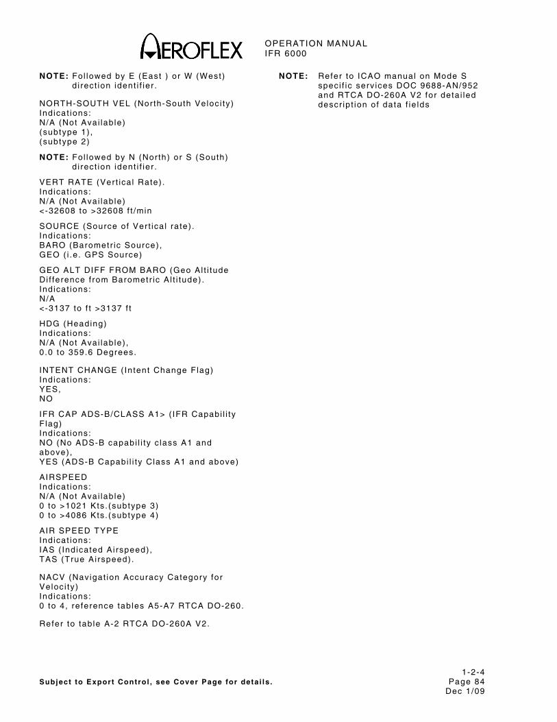
OPERATION MANUAL IFR 6000
1-2-4 Subject to Export Control , see Cover Page for deta i ls . Page 84
Dec 1/09
NOTE: Fol lowed by E (East ) or W (West) d i rect ion ident i f ier .
NORTH-SOUTH VEL (North-South Veloc i ty ) Ind icat ions: N/A (Not Avai lab le) (subtype 1) , (subtype 2)
NOTE: Fol lowed by N (Nor th) or S (South) d i rect ion ident i f ier .
VERT RATE (Ver t ica l Rate) . Ind icat ions: N/A (Not Avai lab le) <-32608 to >32608 f t /min
SOURCE (Source of Ver t ica l ra te) . Ind icat ions: BARO (Barometr ic Source) , GEO ( i .e . GPS Source)
GEO ALT DIFF FROM BARO (Geo Al t i tude Di f ference f rom Barometr ic A l t i tude) . Ind icat ions: N/A <-3137 to f t >3137 f t
HDG (Heading) Ind icat ions: N/A (Not Avai lab le) , 0 .0 to 359.6 Degrees.
INTENT CHANGE ( Intent Change Flag) Ind icat ions: YES, NO
IFR CAP ADS-B/CLASS A1> ( IFR Capabi l i ty F lag) Ind icat ions: NO (No ADS-B capabi l i ty c lass A1 and above) , YES (ADS-B Capabi l i ty Class A1 and above)
AIRSPEED Ind icat ions: N/A (Not Avai lab le) 0 to >1021 Kts . (subtype 3) 0 to >4086 Kts . (subtype 4)
AIR SPEED TYPE Ind icat ions: IAS ( Ind icated Ai rspeed) , TAS (True Ai rspeed) .
NACV (Navigat ion Accuracy Category for Veloc i ty ) Ind icat ions: 0 to 4, re ference tab les A5-A7 RTCA DO-260.
Refer to tab le A-2 RTCA DO-260A V2.
NOTE: Refer to ICAO manual on Mode S speci f ic serv ices DOC 9688-AN/952 and RTCA DO-260A V2 for deta i led descr ip t ion of data f ie lds
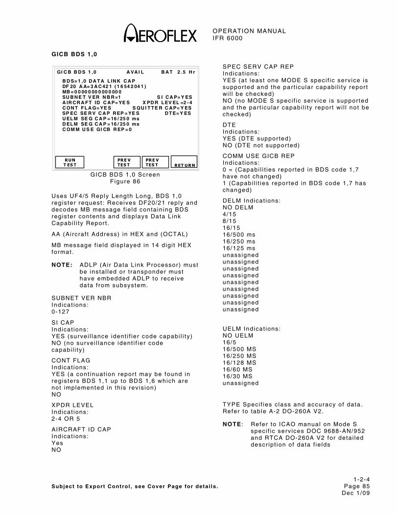
OPERATION MANUAL IFR 6000
1-2-4 Subject to Export Control , see Cover Page for deta i ls . Page 85
Dec 1/09
GICB BDS 1,0
B A T 2 .5 H r
B D S= 1 ,0 D A T A L IN K C A P DF 20 A A= 3 A C 42 1 ( 1 6 54 2 04 1 ) MB = 0 0 00 0 00 0 00 0 00 0 SU B N E T V ER N B R =1 S I C A P= Y ES A IR C R A F T ID C A P= YE S X PD R L EV EL =2 - 4 C ON T F L A G= YE S S QU I T T E R C A P= Y ES SP EC SE R V C A P R EP = YE S D T E= Y ES U EL M SE G C A P = 16 / 25 0 ms D EL M SE G C A P = 16 / 25 0 ms C OM M U S E GI CB R EP = 0
RUN T ES T
PRE V TES T
GI C B B D S 1 ,0 A VA I L
PRE V TES T
RET URN
GICB BDS 1,0 Screen F igure 86
Uses UF4/5 Reply Length Long, BDS 1,0 reg is ter request : Receives DF20/21 rep ly and decodes MB message f ie ld conta in ing BDS reg is ter contents and d isp lays Data L ink Capabi l i ty Repor t .
AA (Ai rcraf t Address) in HEX and (OCTAL)
MB message f ie ld d isp layed in 14 d ig i t HEX format .
NOTE: ADLP (Ai r Data L ink Processor) must be insta l led or t ransponder must have embedded ADLP to receive data f rom subsystem.
SUBNET VER NBR Ind icat ions: 0-127
SI CAP Ind icat ions: YES (surve i l lance ident i f ier code capabi l i ty ) NO (no surve i l lance ident i f ier code capabi l i ty )
CONT FLAG Ind icat ions: YES (a cont inuat ion repor t may be found in reg is ters BDS 1,1 up to BDS 1,6 which are not implemented in th is rev is ion) NO
XPDR LEVEL Ind icat ions: 2-4 OR 5
AIRCRAFT ID CAP Ind icat ions: Yes NO
SPEC SERV CAP REP Ind icat ions: YES (at least one MODE S spec i f ic serv ice is suppor ted and the par t icu lar capabi l i ty repor t wi l l be checked) NO (no MODE S speci f ic serv ice is suppor ted and the par t icu lar capabi l i ty repor t wi l l not be checked)
DTE Ind icat ions: YES (DTE suppor ted) NO (DTE not suppor ted)
COMM USE GICB REP Ind icat ions: 0 = (Capabi l i t ies repor ted in BDS code 1,7 have not changed) 1 (Capabi l i t ies repor ted in BDS code 1,7 has changed)
DELM Ind icat ions: NO DELM 4/15 8/15 16/15 16/500 ms 16/250 ms 16/125 ms unass igned unass igned unass igned unass igned unass igned unass igned unass igned unass igned unass igned
UELM Ind icat ions: NO UELM 16/5 16/500 MS 16/250 MS 16/128 MS 16/60 MS 16/30 MS unass igned
TYPE Speci f ies c lass and accuracy of data. Refer to tab le A-2 DO-260A V2.
NOTE : Refer to ICAO manual on Mode S speci f ic serv ices DOC 9688-AN/952 and RTCA DO-260A V2 for deta i led descr ip t ion of data f ie lds

OPERATION MANUAL IFR 6000
1-2-4 Subject to Export Control , see Cover Page for deta i ls . Page 86
Dec 1/09
GICB BDS 1,7
B A T 2 .5 H r
B D S= 1 ,7 C O M GI C B C A P DF 20 A A= 3 A C 42 1 ( 1 6 54 2 04 1 ) MB = F F F F F F 0 00 00 0 00 : 0 ,5 : 0 ,6 : 0 ,7 : 0 , 8 : 0, 9 : 0, A : 2 ,0 : 2 ,1 : 4 ,0 : 4 , 1 : 4, 2 : 4, 3 : 4 ,4 : 4 ,5 : 4 ,8 : 5 , 0 : 5, 1 : 5, 2 : 5 ,3 : 5 ,4 : 5 ,5 : 5 , 6 : 5, F : 6 ,0
RUN T ES T
PRE V TES T
GI C B B D S 1 ,7 A V A IL
PRE V TES T
RET URN
GICB BDS 1,7 Screen F igure 87
Uses UF4/5 Reply Length Long, BDS 1,7 reg is ter request : Receives DF20/21 rep ly and decodes MB message f ie ld conta in ing BDS reg is ter contents and d isp lays Common GICB Capabi l i ty Repor t .
AA (Ai rcraf t Address) in HEX and (OCTAL)
MB message f ie ld d isp layed in 14 d ig i t HEX format .
Refer to 1-2-4, Table 17. Each BDS regis ter suppor ted by the t ransponder is d isp layed.
NOTE: ADLP (Ai r Data L ink Processor) must be insta l led or t ransponder must have embedded ADLP to receive data f rom subsystem.
NOTE : Refer to ICAO manual on Mode S speci f ic serv ices DOC 9688-AN/952 and RTCA DO-260A V2 for deta i led descr ip t ion of data f ie lds
GICB BDS 1,8 – 1,C
B A T 2 .5 H r
B D S= 1 ,8 S PE C IF I C S ER V # 1 DF 20 A A= 3 A C 42 1 ( 1 6 54 2 04 1 ) MB = F F F F F F F F F F F F F F :0 , 1 : 0 ,2 : 0 ,3 : 0, 4 : 0 ,5 : 0 ,6 : 0, 7 :0 , 8 : 0 ,9 : 0 ,A : 0, B : 0 ,C : 0 ,D : 0, E :0 , F : 1 ,0 : 1 ,1 : 1, 2 : 1 ,3 : 1 ,4 : 1, 5 :1 , 6 : 1 ,7 : 1 ,8 : 1, 9 : 1 ,A : 1 ,B : 1, C :1 , D : 1 ,E : 1 ,F : 2, 0 : 2 ,1 : 2 ,2 : 2, 3 :2 , 4 : 2 ,5 : 2 ,6 : 2, 7 : 2 ,8 : 2 ,9 : 2, A :2 , B : 2 ,C : 2 ,D : 2, E : 2 ,F : 3 ,0 : 3, 1 :3 , 2 : 3 ,3 : 3 ,4 : 3, 5 : 3 ,6 : 3 ,7 : 3, 8
RUNT ES T
PRE VTES T
GI C B B D S 1 ,8 A VA I L
PRE V TES T
RET URN
GICB BDS 1,8 Screen F igure 88
B A T 2 .5 H r
B D S= 1 ,9 S PE C IF I C S ER V # 2 DF 20 A A= 3 A C 42 1 ( 1 6 54 2 04 1 ) MB = F F F F F F F F F F F F F F : 3 ,9 : 3 ,A : 3 ,B : 3 ,C : 3 ,D :3 , E : 3, F : 4 ,0 : 4 ,1 : 4 ,2 : 4 ,3 : 4 ,4 :4 , 5 : 4, 6 : 4 ,7 : 4 ,8 : 4 ,9 : 4 ,A : 4 ,B :4 , C : 4, D : 4 ,E : 4 ,F : 5 ,0 : 5 ,1 : 5 ,2 :5 , 3 : 5, 4 : 5 ,5 : 5 ,6 : 5 ,7 : 5 ,8 : 5 ,9 :5 , A : 5, B : 5 ,C : 5 ,D : 5 ,E : 5 ,F : 6 ,0 :6 , 1 : 6, 2 : 6 ,3 : 6 ,4 : 6 ,5 : 6 ,6 : 6 ,7 :6 , 8 : 6, 9 : 6 ,A : 6 ,B : 6 ,C : 6 ,D : 6 ,E :6 , F : 7, 0
RUNT ES T
PRE VTES T
GI C B B D S 1 ,9 A V A IL
PRE V TES T
RET URN
GICB BDS 1,9 Screen F igure 89
B A T 2 .5 H r
B D S= 1 ,A SP EC I F IC SE R V #3 DF 20 A A= 3 A C 42 1 ( 1 6 54 2 04 1 ) MB = F F F F F F F F F F F F F F :7 , 1 : 7 ,2 : 7 ,3 : 7, 4 : 7 ,5 :7 , 6 : 7, 7 :7 , 8 : 7 ,9 : 7 ,A : 7, B : 7 ,C :7 , D : 7, E :7 , F : 8 ,0 : 8 ,1 : 8, 2 : 8 ,3 :8 , 4 : 8, 5 :8 , 6 : 8 ,7 : 8 ,8 : 8, 9 : 8 ,A :8 , B : 8, C :8 , D : 8 ,E : 8 ,F : 9, 0 : 9 ,1 :9 , 2 : 9, 3 :9 , 4 : 9 ,5 : 9 ,6 : 9, 7 : 9 ,8 :9 , 9 : 9, A :9 , B : 9 ,C : 9 ,D : 9, E : 9 ,F :A , 0 : A ,1 :A , 2 : A ,3 : A , 4 : A ,5 : A ,6 :A , 7 : A ,8
RUNT ES T
PRE VTES T
GI C B B D S 1 , A A VA IL
PRE V TES T
RET URN
GICB BDS 1,A Screen F igure 90

OPERATION MANUAL IFR 6000
1-2-4 Subject to Export Control , see Cover Page for deta i ls . Page 87
Dec 1/09
B A T 2 .5 H r
B D S= 1 ,B SP EC I F IC SE R V #4 DF 20 A A= 3 A C 42 1 ( 1 6 54 2 04 1 ) MB = F F F F F F F F F F F F F F :A , 9 : A ,A : A , B : A ,C : A ,D :A , E : A ,F :B , 0 : B ,1 : B , 2 : B ,3 : B ,4 :B , 5 : B ,6 :B , 7 : B ,8 : B , 9 : B ,A : B ,B :B , C : B ,D :B , E : B ,F : C , 0 : C ,1 : C ,2 :C , 3 : C ,4 :C , 5 : C ,6 : C , 7 : C ,8 : C ,9 :C , A : C ,B :C , C : C ,D : C , E : C ,F : D ,0 :D , 1 : D ,2 :D , 3 : D ,4 : D , 5 : D ,6 : D ,7 :D , 8 : D ,9 :D , A : D ,B : D , C : D ,D : D ,E :D , F : E, 0
RUN T ES T
PRE V TES T
GI C B B D S 1 ,B A VA IL
PRE V TES T
RET URN
GICB BDS 1,B Screen F igure 91
B A T 2 .5 H r
B D S= 1 ,C SP EC I F IC SE R V #5 DF 20 A A= 3 A C 42 1 ( 1 6 54 2 04 1 ) MB = 0 0 00 0 0F F F F F F F F :E ,1 : E, 2 : E ,3 : E, 4 : E, 5 :E ,6 : E, 7 :E ,8 : E, 9 : E ,A : E, B : E, C :E ,D : E, E :E ,F : F ,0 : F , 1 : F ,2 : F , 3 :F ,4 : F ,5 :F ,6 : F ,7 : F , 8 : F ,9 : F , A :F ,B : F ,C :F ,D : F ,E : F , F
RUN T ES T
PRE V TES T
GI C B B D S 1 ,C A VA IL
PRE V TES T
RET URN
GICB BDS 1,C Screen F igure 92
Uses UF4/5 Reply Length Long, BDS 1,8 through 1,C reg is ter requests : Receives DF20/21 rep ly and decodes MB message f ie ld conta in ing BDS regis ter contents and d isp lays Mode S Speci f ic Serv ice GICB Capabi l i ty Repor ts #1 through #5.
AA (Ai rcraf t Address) in HEX and (OCTAL)
MB message f ie ld d isp layed in 14 d ig i t HEX format .
Mode S Speci f ic Serv ice GICB Capabi l i ty Repor ts adv ise which BDS regis ters are current ly avai lab le f rom the t ransponder for data download v ia GICB protocol .
NOTE: ADLP (Ai r Data L ink Processor) must be insta l led or t ransponder must have embedded ADLP to receive data f rom subsystem.
NOTE: Refer to ICAO manual on Mode S speci f ic serv ices DOC 9688-AN/952 and RTCA DO-260A V2 for deta i led descr ip t ion of data f ie lds

OPERATION MANUAL IFR 6000
1-2-4 Subject to Export Control , see Cover Page for deta i ls . Page 88
Dec 1/09
GICB BDS 1,D – 1,F
B A T 2 .5 H r
B D S= 1 ,D MS P C A P R PT 1 - 28 DF 20 A A= 3 A C 42 1 ( 1 6 54 2 04 1 ) MB = F F F F F F F F F F F F F F U PL I N K 1 2 3 4 5 6 7 8 1 0 11 1 2 13 1 4 15 1 6 17 1 8 19 2 0 2 1 22 2 3 25 2 6 27 2 8 D OW N L IN K 1 2 3 4 5 6 7 8 1 0 11 1 2 13 1 4 15 1 6 17 1 8 19 2 0 2 1 22 2 3 25 2 6 27 2 8
RUN T ES T
PRE V TES T
GI C B B D S 1 ,D A VA IL
PRE V TES T
RET URN
GICB BDS 1,D Screen F igure 93
B A T 2 .5 H r
B D S= 1 ,E M S P C AP R P T 29 - 56 DF 20 A A= 3 A C 42 1 ( 1 6 54 2 04 1 ) MB = F F F F F F F F F F F F F F U PL I N K 2 9 3 0 31 3 2 3 3 34 3 5 3 6 37 38 3 9 4 0 4 1 4 2 43 4 4 4 5 46 4 7 4 8 49 50 5 1 5 2 5 3 5 4 55 5 6 D OW N L IN K 2 9 3 0 31 3 2 3 3 34 3 5 3 6 37 38 3 9 4 0 4 1 4 2 43 4 4 4 5 46 4 7 4 8 49 50 5 1 5 2 5 3 5 4 55 5 6
RUN T ES T
PRE V TES T
GI C B B D S 1 ,E A V A IL
PRE V TES T
RET URN
GICB BDS 1,E Screen F igure 94
B A T 2 .5 H r
B D S= 1 ,F M SP C A P R PT 5 7- 6 3 DF 20 A A= 3 A C 42 1 ( 1 6 54 2 04 1 ) MB = F F F F F F F F F F F F F F U PL I N K 5 7 58 59 6 0 6 1 6 2 63 D OW N L IN K 5 7 58 59 6 0 6 1 6 2 63
RUN T ES T
PRE V TES T
GI C B B D S 1 ,F A VA I L
PRE V TES T
RET URN
GICB BDS 1,F Screen F igure 95
Uses UF4/5 Reply Length Long, BDS 1,D through 1,F reg is ter requests : Receives DF20/21 rep ly and decodes MB message f ie ld conta in ing BDS regis ter contents and d isp lays Mode S Speci f ic Protocol Capabi l i ty Repor ts 1,D MSP channels 1-28, 1 ,E MSP Channels 29-56, 1 ,F MSP channels 57-63.
AA (Ai rcraf t Address) in HEX and (OCTAL)
MB message f ie ld d isp layed in 14 d ig i t HEX format .
Mode S Speci f ic Protocols (MSPs) ut i l ize one or more of the 63 upl ink or downl ink channels prov ided by th is protocol to t ransfer data in e i ther shor t or long form MSP packets f rom the GDLP (Ground Data L ink Processor) to the ADLP (Ai rborne Data L ink Processor) or v ice versa. The avai lab le channels are d isp layed over three screens BDS 1,D BDS 1,E and BDS 1,F.
NOTE: Refer to ICAO manual on Mode S speci f ic serv ices DOC 9688-AN/952 and RTCA DO-260A V2 for deta i led descr ip t ion of data f ie lds

OPERATION MANUAL IFR 6000
1-2-4 Subject to Export Control , see Cover Page for deta i ls . Page 89
Dec 1/09
GICB BDS 2,0
B A T 2 .5 H r
B D S= 2 ,0 F L IG H T I D DF 20 A A= 3 A C 42 1 ( 1 6 54 2 04 1 ) MB = 0 0 00 0 00 0 00 0 00 0 F L IG H T I D = U A6 6 12 1
RUN T ES T
PRE V TES T
GI C B B D S 2 ,0 A V A IL
PRE V TES T
RET URN
GICB BDS 2,0 Screen F igure 96
Uses UF4/5 Reply Length Long, BDS 2,0 reg is ter request : Receives DF20/21 rep ly and decodes MB message f ie ld conta in ing BDS regis ter contents and d isp lays AIS F l ight ID.
AA (Ai rcraf t Address) in HEX and (OCTAL)
MB message f ie ld d isp layed in 14 d ig i t HEX format .
F l ight Id is seven characters .
GICB BDS 2,1
B A T 2 .5 H r
B D S= 2 ,1 A IR C R A F T R EG # DF 20 A A= 3 A C 42 1 ( 1 6 54 2 04 1 ) MB = 0 0 00 0 00 0 00 0 00 0 A R N =1 2 34 5 A B A R = AA
RUNT ES T
PRE V TES T
GI C B B D S 2 ,1 A V A IL
PRE VTES T
RET URN
GICB BDS 2,1 Screen F igure 97
Uses UF20/21 BDS 2,1 reg is ter request : Receives DF20/21 rep ly and decodes MB message f ie ld conta in ing BDS regis ter contents and d isp lays Ai rcraf t Regis t ra t ion Number.
AA (Ai rcraf t Address) in HEX and (OCTAL)
MB message f ie ld d isp layed in 14 d ig i t HEX format .
ARN (Ai rcraf t Regis t ra t ion Number) up to seven characters .
AR (Ai r l ine Regis t ra t ion) two characters .

OPERATION MANUAL IFR 6000
1-2-4 Subject to Export Control , see Cover Page for deta i ls . Page 90
Dec 1/09
GICB BDS 3,0
B A T 2 .5 H r
B D S= 3 ,0 A C A S A R A DF 20 A A= 3 A C 42 1 ( 1 6 54 2 04 1 ) MB = 0 0 00 0 00 0 00 0 00 0 T ID B = 7 0 d e g T ID A = 3 2 00 0 f t T ID R = 1 .0 0 n m A R A =1 1 10 1 01 0 00 0 00 0 T I D =3 A 4 51 8 R A C =1 0 10 R A T = 1 MT E= 3 T H R EA T A D D R ES S= N / A T T I= 2 - A L T /R AN G E/ B EA R I NG D AT A
RUN T ES T
PRE V TES T
GI C B B D S 3 ,0 A V A IL
PRE V TES T
RET URN
GICB BDS 3,0 Screen F igure 98
Uses UF4/5 Reply Length Long, BDS 3,0 reg is ter request : Receives DF20/21 rep ly and decodes MB message f ie ld conta in ing BDS regis ter contents and d isp lays ACAS Act ive Resolut ion Advisory data.
AA (Ai rcraf t Address) in HEX and (OCTAL)
MB message f ie ld d isp layed in 14 d ig i t HEX format .
ARA (Act ive Resolut ion Advisor ies) b i ts 41-54 d isp layed in b inary .
RAC (Resolut ion Advisory Compl iment) b i t 55-58 d isp layed in b inary.
RAT (RA Terminated) ind icator b i t 59 d isp layed in b inary. Note: Normal ly 0 unt i l an RA is terminated, then wi l l be 1 for 18 seconds.
TIDA (Threat Ident i ty Data Al t i tude) d isp layed in feet . N/A (Not Avai lab le) Note: Only d isp layed when TTI = 2, In t ruder Not Mode S Equipped.
TID (Threat Ident i ty Data) Mode S address (HEX) of the threat . Note: Only d isp layed when TTI = 1.
TIDR (Threat Ident i ty Data Range) in nm. N/A (Not Avai lab le) Note: Only d isp layed when TTI = 2, In t ruder Not Mode S Equipped.
TIDB (Threat Ident i ty Data Bear ing) in degrees. N/A (Not Avai lab le) Note: Only d isp layed when TTI = 2, In t ruder Not Mode S Equipped.
THREAT ADDRESS (Mode S threat address) d isp layed in 6 HEX d ig i ts N/A (Not Avai lab le) Note: Only d isp layed when TTI = 1.
MTE (Mul t ip le Threat Encounter) d isp layed in 1 b i t b inary.
TTI (Threat Type Ind icator) Ind icat ions: 0-NO DATA 1-MODE S ADDRESS 2-ALT/RANGE/BEARING DATA 3-NOT ASSIGNED
NOTE : Refer to ICAO Annex 10, Vol l I I , Par t 1 , Chapter 5 and RTCA-DO-260A V2 for deta i led descr ip t ion of data f ie lds. A lso refer to RTCA D0-185A para 2.2.3.9.3.2.3 MB f ie lds used by TCASII

OPERATION MANUAL IFR 6000
1-2-4 Subject to Export Control , see Cover Page for deta i ls . Page 91
Dec 1/09
GICB BDS 4,0
B A T 2 .5 H r
B D S= 4 ,0 VE R T I N T EN T DF 20 A A= 3 A C 42 1 ( 1 6 54 2 04 1 ) MB = 0 0 00 0 00 0 00 0 00 0 MC P /F CU S EL AL T = 6 55 3 6 f t F M S SE L A L T = 65 5 36 f t A P P M OD E= Y E S SO U RC E IN F O= Y ES M O DE IN F O= Y ES T A R GE T A L T = F C U / MC P SE L A L T VN A V H OL D M OD E A C T I VE = YE S AL T H O L D M OD E A C T IV E = YE S B A RO P R ES S ET = 11 00 . 0 mb
RUN T ES T
PRE V TES T
GI C B B D S 4 ,0 A V A IL
PRE V TES T
RET URN
GICB BDS 4,0 Screen F igure 99
Uses UF4/5 Reply Length Long, BDS 4,0 reg is ter request : Receives DF20/21 rep ly and decodes MB message f ie ld conta in ing BDS regis ter contents and d isp lays Ver t ica l In tent .
AA (Ai rcraf t Address) in HEX and (OCTAL)
MB message f ie ld d isp layed in 14 d ig i t HEX format .
NOTE: ADLP (Ai r Data L ink Processor) must be insta l led or t ransponder must have embedded ADLP to receive data f rom subsystem.
MCP/FCU SEL ALT (Mode Contro l Panel /F l ight Contro l Uni t Selected Al t i tude) Ind icat ions in feet . N/A (Not Avai lab le)
FMS SEL ALT (F l ight management System) Ind icat ions in feet . N/A (Not Avai lab le)
TARGET ALT (Target A l t i tude) Ind icat ions: N/A (Not Avai lab le) UNKNOWN, AIRCRAFT ALT, FCU/MCP SEL ALT, FMS SEL ALT
SOURCE INFO (Target Al t i tude Source In format ion) Ind icat ions: YES (Source in format ion Prov ided) , NO (No Source In format ion Prov ided)
BARO PRES SET (Barometr ic Pressure set) Ind icat ions: N/A (Not Avai lab le) 800 to 1209.5 in mb.
VNAV HOLD MODE (Ver t ica l Navigat ion Mode) Ind icat ions: YES, NO (Not Act ive)
ALT HOLD MODE (Al t i tude Hold Mode) Ind icat ions: YES, NO (Not Act ive)
APP MODE (Approach Mode) Ind icat ions: YES, NO (Not Act ive)
MODE INFO (Mode Informat ion) Ind icat ions YES (Mode Informat ion Prov ided) , NO (No Mode Informat ion Prov ided) .
NOTE : Refer to ICAO manual on Mode S speci f ic serv ices DOC 9688-AN/952 and RTCA DO-260A V2 for deta i led descr ip t ion of data f ie lds.
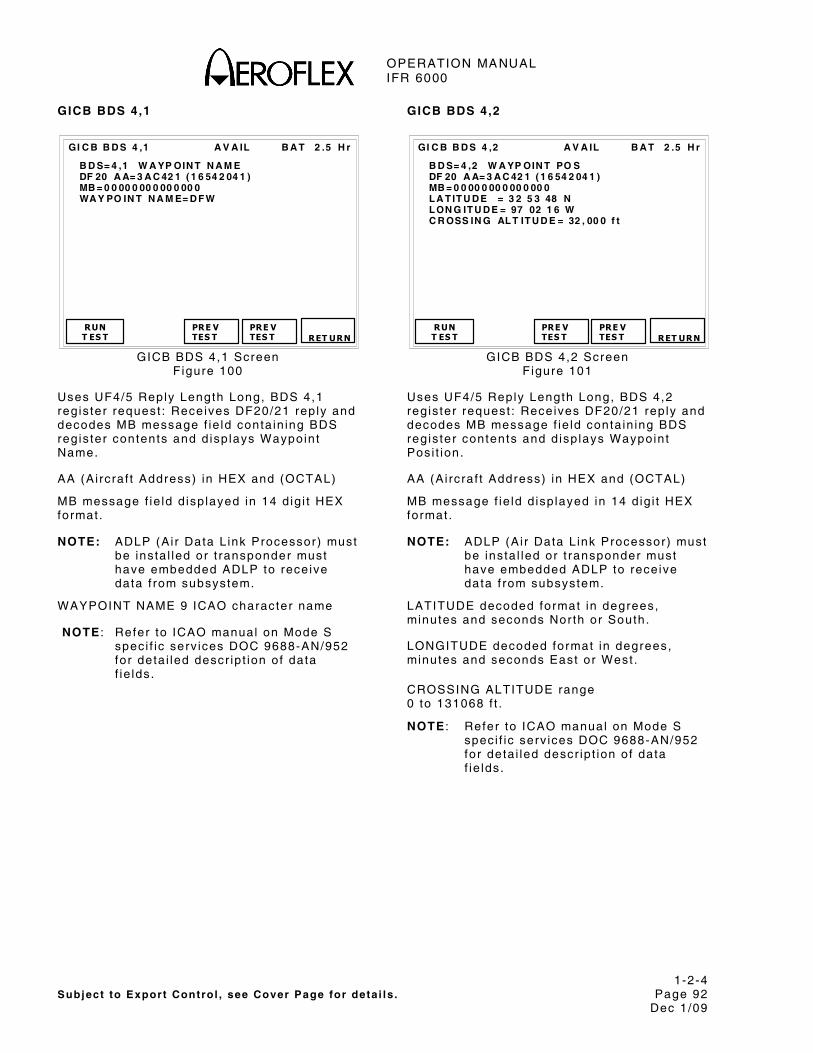
OPERATION MANUAL IFR 6000
1-2-4 Subject to Export Control , see Cover Page for deta i ls . Page 92
Dec 1/09
GICB BDS 4,1
B A T 2 .5 H r
B D S= 4 ,1 W A YP OIN T N A M E DF 20 A A= 3 A C 42 1 ( 1 6 54 2 04 1 ) MB = 0 0 00 0 00 0 00 0 00 0 WA Y PO IN T N A M E= D F W
RUN T ES T
PRE V TES T
GI C B B D S 4 ,1 A V A IL
PRE V TES T
RET URN
GICB BDS 4,1 Screen F igure 100
Uses UF4/5 Reply Length Long, BDS 4,1 reg is ter request : Receives DF20/21 rep ly and decodes MB message f ie ld conta in ing BDS reg is ter contents and d isp lays Waypoint Name.
AA (Ai rcraf t Address) in HEX and (OCTAL)
MB message f ie ld d isp layed in 14 d ig i t HEX format .
NOTE: ADLP (Ai r Data L ink Processor) must be insta l led or t ransponder must have embedded ADLP to receive data f rom subsystem.
WAYPOINT NAME 9 ICAO character name
NOTE : Refer to ICAO manual on Mode S speci f ic serv ices DOC 9688-AN/952 for deta i led descr ip t ion of data f ie lds.
GICB BDS 4,2
B A T 2 .5 H r
B D S= 4 ,2 W A YP OIN T PO S DF 20 A A= 3 A C 42 1 ( 1 6 54 2 04 1 ) MB = 0 0 00 0 00 0 00 0 00 0 L A T IT U D E = 3 2 5 3 48 N L ON G IT U D E = 97 02 1 6 W C R OSS IN G AL T IT U D E = 32 , 00 0 f t
RUNT ES T
PRE VTES T
GI C B B D S 4 ,2 A V A IL
PRE V TES T
RET URN
GICB BDS 4,2 Screen F igure 101
Uses UF4/5 Reply Length Long, BDS 4,2 reg is ter request : Receives DF20/21 rep ly and decodes MB message f ie ld conta in ing BDS reg is ter contents and d isp lays Waypoint Posi t ion.
AA (Ai rcraf t Address) in HEX and (OCTAL)
MB message f ie ld d isp layed in 14 d ig i t HEX format .
NOTE: ADLP (Ai r Data L ink Processor) must be insta l led or t ransponder must have embedded ADLP to receive data f rom subsystem.
LATITUDE decoded format in degrees, minutes and seconds Nor th or South.
LONGITUDE decoded format in degrees, minutes and seconds East or West .
CROSSING ALTITUDE range 0 to 131068 f t .
NOTE : Refer to ICAO manual on Mode S speci f ic serv ices DOC 9688-AN/952 for deta i led descr ip t ion of data f ie lds.
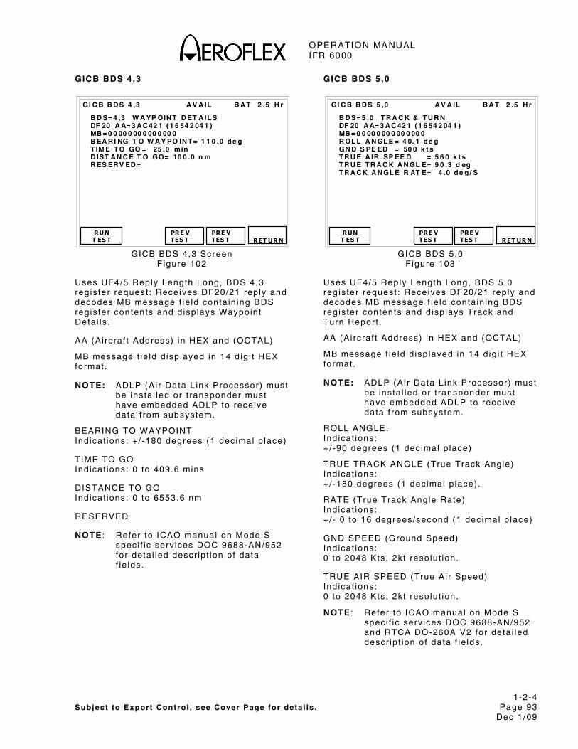
OPERATION MANUAL IFR 6000
1-2-4 Subject to Export Control , see Cover Page for deta i ls . Page 93
Dec 1/09
GICB BDS 4,3
B A T 2 .5 H r
B D S= 4 ,3 W A YP OIN T D ET A IL S DF 20 A A= 3 A C 42 1 ( 1 6 54 2 04 1 ) MB = 0 0 00 0 00 0 00 0 00 0 B EA R I NG T O W A Y PO IN T = 1 1 0 .0 d e g T IM E T O GO = 25 .0 min D IST A N C E T O GO= 10 0 .0 n m R ES ER V ED =
RUN T ES T
PRE V TES T
GI C B B D S 4 ,3 A V A IL
PRE V TES T
RET URN
GICB BDS 4,3 Screen F igure 102
Uses UF4/5 Reply Length Long, BDS 4,3 reg is ter request : Receives DF20/21 rep ly and decodes MB message f ie ld conta in ing BDS reg is ter contents and d isp lays Waypoint Deta i ls .
AA (Ai rcraf t Address) in HEX and (OCTAL)
MB message f ie ld d isp layed in 14 d ig i t HEX format .
NOTE: ADLP (Ai r Data L ink Processor) must be insta l led or t ransponder must have embedded ADLP to receive data f rom subsystem.
BEARING TO WAYPOINT Ind icat ions: +/ -180 degrees (1 dec imal p lace)
TIME TO GO Ind icat ions: 0 to 409.6 mins
DISTANCE TO GO Ind icat ions: 0 to 6553.6 nm
RESERVED
NOTE : Refer to ICAO manual on Mode S speci f ic serv ices DOC 9688-AN/952 for deta i led descr ip t ion of data f ie lds.
GICB BDS 5,0
B A T 2 .5 H r
B D S= 5 ,0 T R A C K & T U R N DF 20 A A= 3 A C 42 1 ( 1 6 54 2 04 1 ) MB = 0 0 00 0 00 0 00 0 00 0 R OL L A N GL E = 4 0. 1 d e g GN D S PE ED = 50 0 k t s T R U E A IR SP EE D = 5 6 0 k t s T R U E T R A C K A N GL E= 9 0 .3 d eg T R A C K A N GL E R AT E= 4 .0 d e g / S
RUNT ES T
PRE V TES T
GI C B B D S 5 ,0 A V A IL
PRE VTES T
RET URN
GICB BDS 5,0 F igure 103
Uses UF4/5 Reply Length Long, BDS 5,0 reg is ter request : Receives DF20/21 rep ly and decodes MB message f ie ld conta in ing BDS reg is ter contents and d isp lays Track and Turn Repor t .
AA (Ai rcraf t Address) in HEX and (OCTAL)
MB message f ie ld d isp layed in 14 d ig i t HEX format .
NOTE: ADLP (Ai r Data L ink Processor) must be insta l led or t ransponder must have embedded ADLP to receive data f rom subsystem.
ROLL ANGLE. Ind icat ions: +/ -90 degrees (1 dec imal p lace)
TRUE TRACK ANGLE (True Track Angle) Ind icat ions: +/ -180 degrees (1 dec imal p lace) .
RATE (True Track Angle Rate) Ind icat ions: +/ - 0 to 16 degrees/second (1 dec imal p lace)
GND SPEED (Ground Speed) Ind icat ions: 0 to 2048 Kts , 2kt resolut ion.
TRUE AIR SPEED (True Ai r Speed) Ind icat ions: 0 to 2048 Kts , 2kt resolut ion.
NOTE : Refer to ICAO manual on Mode S speci f ic serv ices DOC 9688-AN/952 and RTCA DO-260A V2 for deta i led descr ip t ion of data f ie lds.

OPERATION MANUAL IFR 6000
1-2-4 Subject to Export Control , see Cover Page for deta i ls . Page 94
Dec 1/09
GICB BDS 6,0
B A T 2 .5 H r
B D S= 6 ,0 H D G & S PE ED DF 20 A A= 3 A C 42 1 ( 1 6 54 2 04 1 ) MB = 0 0 00 0 00 0 00 0 00 0 IN D AI R S P EE D = 51 2 k t s M A C H = 0. 72 9 B A RO AL T R A T E = 1 40 0 f t / min M AG H D G = 18 0. 0 d e g IN E R T V ER T VE L = 14 0 0 f t /mi n
RUN T ES T
PRE V TES T
GI C B B D S 6 ,0 A V A IL
PRE V TES T
RET URN
GICB BDS 6,0 Screen F igure 104
Uses UF4/5 Reply Length Long, BDS 6,0 reg is ter request : Receives DF20/21 rep ly and decodes MB message f ie ld conta in ing BDS reg is ter contents and d isp lays Heading and Speed Repor t .
AA (Ai rcraf t Address) in HEX and (OCTAL)
MB message f ie ld d isp layed in 14 d ig i t HEX format .
NOTE: ADLP (Ai r Data L ink Processor) must be insta l led or t ransponder must have embedded ADLP to receive data f rom subsystem.
IND AIR SPEED ( Indicated Ai r Speed) Ind icat ions: N/A (Not Avai lab le) 0 to 1023 Kts , 1 k t resolut ion.
MACH (Mach Number) Ind icat ions: N/A (Not Avai lab le) 0 to 4.096 mach number, resolut ion to three dec imal p laces.
BARO ALT RATE (Barometr ic A l t i tude Rate) Ind icat ions: N/A (Not Avai lab le) -16384 to +16352 f t / minute, resolut ion 32 f t /min.
MAG HDG (Magnet ic Heading) Ind icat ions: N/A (Not Avai lab le) 0 to 359 degrees.
INERT VERT VEL ( Iner t ia l Ver t ica l Veloc i ty ) Ind icat ions: N/A (Not Avai lab le) -16384 to +16352 f t / minute, resolut ion 32 f t /min.
NOTE: Refer to ICAO manual on Mode S spec i f ic serv ices DOC 9688-AN/952 and RTCA DO-260A V2 for deta i led descr ip t ion of data f ie lds.
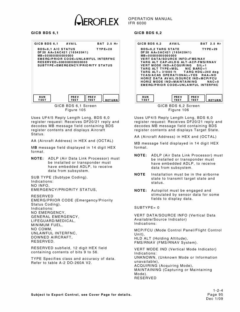
OPERATION MANUAL IFR 6000
1-2-4 Subject to Export Control , see Cover Page for deta i ls . Page 95
Dec 1/09
GICB BDS 6,1
B A T 2 .5 H r
B D S= 6 ,1 A / C S T A T U S T YP E= 2 8 DF 20 A A= 3 A C 42 1 ( 1 6 54 2 04 1 ) MB = 0 0 00 0 00 0 00 0 00 0 EM E RG /P R IO R C O D E= U N L A W F U L IN T ER F N C R ES ER V ED = 0 00 0 00 0 00 0 00 0 0 SU B T Y PE = EM E RG EN C Y /P R IO R IT Y S T A T U S
RUN T ES T
PRE V TES T
GI C B B D S 6 ,1 A VA I L
PRE V TES T
RET URN
GICB BDS 6,1 Screen F igure 105
Uses UF4/5 Reply Length Long, BDS 6,0 reg is ter request : Receives DF20/21 rep ly and decodes MB message f ie ld conta in ing BDS regis ter contents and d isp lays Ai rcraf t Status.
AA (Ai rcraf t Address) in HEX and (OCTAL)
MB message f ie ld d isp layed in 14 d ig i t HEX format .
NOTE: ADLP (Ai r Data L ink Processor) must be insta l led or t ransponder must have embedded ADLP, to receive data f rom subsystem.
SUB TYPE (Subtype Coding) . Ind icat ions: NO INFO, EMERGENCY/PRIORITY STATUS,
RESERVED EMERG/PRIOR CODE (Emergency/Pr ior i ty Status Coding) . Ind icat ions: NO EMERGENCY, GENERAL EMERGENCY, LIFEGUARD/MEDICAL, MINIMUM FUEL, NO COMM, UNLAWFUL INTERFNC, DOWNED AIRCRAFT, RESERVED.
RESERVED subf ie ld , 12 d ig i t HEX f ie ld conta in ing contents of b i ts 9 to 56.
TYPE Speci f ies c lass and accuracy of data. Refer to tab le A-2 DO-260A V2.
GICB BDS 6,2
B A T 2 .5 H r
B D S= 6 ,2 T A R G S T A T E T Y PE = 29 DF 20 A A= 3 A C 42 1 ( 1 6 54 2 04 1 ) MB = 0 0 00 0 00 0 00 0 00 0 VE R T D A T A / SO U R C E IN F O =F MS /N A V T A R G AL T C A P =H L D G AL T - A C P- F M S/ R N A V VE R T M OD E I N D = A C QU IR IN G S IL = 1 T A R G AL T T Y PE = M SL N IC B AR O = 1 T A R G AL T = 3 10 0 0 f t T A R G H D G = 24 0 d e g T C A S/ A C AS OPE R A T I ON A L = Y ES R A A = N O H OR IZ D A T A AV A IL /S OU R C E IN D = M C P/ F C U H OR IZ M OD E I N D = M AI N T A IN I N G N A C = 0 EM E RG /P R IO R C O D E= U N L A W F U L IN T ER F N C
RUNT ES T
PRE V TES T
GI C B B D S 6 ,2 A VA I L
PRE VTES T
RET URN
GICB BDS 6,2 Screen F igure 106
Uses UF4/5 Reply Length Long, BDS 6,0 reg is ter request : Receives DF20/21 rep ly and decodes MB message f ie ld conta in ing BDS regis ter contents and d isp lays Target State.
AA (Ai rcraf t Address) in HEX and (OCTAL)
MB message f ie ld d isp layed in 14 d ig i t HEX format .
NOTE: ADLP (Ai r Data L ink Processor) must be insta l led or t ransponder must have embedded ADLP, to receive data f rom subsystem.
NOTE Insta l la t ion must be in the a i rborne s tate to t ransmi t target s ta te and s ta tus.
NOTE: Autopi lo t must be engaged and s t imulated by sensor data for some f ie lds to d isp lay data.
SUBTYPE= 0
VERT DATA/SOURCE INFO (Vert ica l Data Avai lab le/Source Ind icator) Ind icat ions:
MCP/FCU (Mode Contro l Panel /F l ight Contro l Uni t ) , HLD ALT (Hold ing Al t i tude) , FMS/RNAV (FMS/RNAV System).
VERT MODE IND (Ver t ica l Mode Ind icator) Ind icat ions: UNKNOWN, (Unknown Mode or In format ion unavai lab le) , ACQUIRING (Acqui r ing Mode) , MAINTAINING (Captur ing or Mainta in ing Mode) . RESERVED

OPERATION MANUAL IFR 6000
1-2-4 Subject to Export Control , see Cover Page for deta i ls . Page 96
Dec 1/09
TARGET ALT CAP (Target Al t i tude Capabi l i ty ) Ind icat ions: HLD-ALT (Capabi l i ty for repor t ing Hold ing a l t i tude only) , HOLD+AUTOPILOT (Capabi l i ty for repor t ing e i ther Hold ing a l t i tude or Autopi lo t cont ro l panel se lected a l t i tude) , HOLD+AUTOPILOT+FMS/RNAV (Capabi l i ty for repor t ing e i ther Hold ing a l t i tude or Autopi lo t cont ro l panel se lected a l t i tude, or any FMS/RNAV level o f f a l t i tude) . RESERVED
H DATA AVAIL/SOURCE IND (Hor izonta l Data Avai lab le/Source Ind icator) Ind icat ions: NOT VALID (No Val id Hor izonta l Target State Data is avai lab le) , MCP/FCU (Mode Contro l Panel /F l ight Contro l Uni t se lected t rack angle) , MAINTAIN (Mainta in Current Heading or Track angle) , FMS/RNAV (FMS/RNAV System)
TARGET HDG (Target Heading Angle) Ind icat ions: 0 to 359 degrees. INVALID
HORIZ MODE IND (Hor izonta l Mode Ind icator) Ind icat ions: UNKNOWN (Unknown Mode or In format ion unavai lab le) , ACQUIRING (Acqui r ing Mode) , MAINTAINING (Captur ing or Mainta in ing Mode) , RESERVED.
NIC BARO (Navigat ion In tegr i ty Baro) Ind icat ions: 0 (Gi l lum Cross Checked) 1 (Gi l lum Not Cross Checked)
SIL (Surve i l lance In tegr i ty Level ) Ind icat ions: 0 (Unknown), 1 (1x10(-3) per f l ight ) , 2 (1x10(-5) per f l ight ) , 3 (1x10(-7) per f l ight )
TCAS/ACAS OPERATIONAL (TCAS/ACAS Operat ional ) Ind icat ions: YES, NO.
RAA (TCAS/ACAS Resolut ion Adv isory Act ive) Ind icat ions: YES, NO. TYPE Speci f ies c lass and accuracy of data. Refer to tab le A-2 RTCA DO-260A V2.
NOTE: Refer to ICAO Annex 10 Vol l I I Chapter 5 and RTCA-DO-260A for deta i led descr ip t ion of data f ie lds.

OPERATION MANUAL IFR 6000
1-2-4 Subject to Export Control , see Cover Page for deta i ls . Page 97
Dec 1/09
GICB BDS 6,5
B A T 2 .5 H r
B D S= 6 ,5 A /C OP S T A T U S T Y PE = 31 DF 20 A A= 3 A C 42 1 ( 1 6 54 2 04 1 ) M E= 00 0 00 0 00 0 0 00 00 SU B T Y PE = 0- A I R B OR N E C A P C L A SS = 00 0 0 N A C = 5 B AQ = 0 SI L = 1 T C = 0 C D T I= 0 A R V= 0 T S =0 R A = 0 VE R N B R = D O- 2 60 A / D O- 2 42 N OT - T C AS = 0 OP ER MO D E SU B F I EL D = 3 N I C B A R O= 1 H OR IZ R EF D I R= T RU E N O R T H ID E N T = 0 T R K /H D G =N / A N I C =5 L EN G T H /W ID T H = N / A R EC AT C S ER V =0 B 2 L O W =N / A P OA = N / A
RUN T ES T
PRE V TES T
GI C B B D S 6 ,5 AV A IL
PRE V TES T
RET URN
GICB 6,5 Screen F igure 107
DF20,21: Receives extended squi t ter decodes and d isp lays Ai rcraf t Operat ional Status.
AA (Ai rcraf t Address) in HEX and (OCTAL)
ME message f ie ld d isp layed in 14 d ig i t HEX format .
NOTE: ADLP (Ai r Data L ink Processor) must be insta l led or t ransponder must have embedded ADLP, to receive data f rom subsystem.
NOTE Data is d isp layed over three screens Par t 1 , Par t 2 and Par t 3 .
SUBTYPE Ind icat ions: AIRBORNE (Ai rborne Status message) , SURFACE (Sur face Status message) , RESERVED, RESERVED, RESERVED, RESERVED, RESERVED, RESERVED,
VER NBR (Repor ts formats and protocols suppor ted) Ind icat ions: 260/242 (RTCA DO-260 and DO-242) , 260A/242A (RTCA DO-260A and DO-242A), RESERVED, RESERVED, RESERVED, RESERVED, RESERVED, RESERVED,
CDTI (Cockpi t Disp lay of Traf f ic In format ion) Ind icat ions: 1 (Traf f ic Disp lay operat ional ) , 0 (Traf f ic Disp lay not operat ional )
ARV (Ai r Referenced Veloc i ty Repor t ) Only Avai lab le when Subtype= Ai rborne. Ind icat ions: N/A (Sur face) 1 (Capabi l i ty o f sending messages to suppor t A i r -Reference ve loc i ty) , 0 (No Capabi l i ty o f sending messages to suppor t A i r -Reference ve loc i ty) .
TS (Target State Repor t Capabi l i ty ) Only Avai lab le when Subtype= Ai rborne Ind icat ions: N/A (Sur face) 1 (Capabi l i ty o f sending messages to suppor t Target State Repor ts) , 0 (No Capabi l i ty o f sending messages to suppor t Target State Repor ts) .
TC (Target Change Repor t Capabi l i ty ) Only Avai lab le when Subtype= Ai rborne. Ind icat ions: N/A (Sur face) 0 (No capabi l i ty for sending messages to suppor t t ra jectory change repor ts) , 1TC+0 (Capabi l i ty o f sending messages to suppor t TC+0 repor t on ly) , 2 MTC (Capabi l i ty o f sending in format ion for mul t ip le TC repor ts) 3 (Reserved)
TRK ANGLE/HDG (Used for sur face ADS-B par t ic ipants , sur face pos i t ion message heading or ground t rack determinat ion b i t ) Ind icat ions: N/A (Ai rborne) 0 (Target Heading Angle Repor ted 1 (Target Angle Repor ted)
IDENT ( Ident Swi tch) Ind icat ions YES ( Ident swi tch act ive) , NO ( Ident swi tch not act ive) .
REC ATC SER (Receiv ing ATC Serv ices) Ind icat ions: 1 (A i rcraf t receiv ing ATC serv ices) , 0 (A i rcraf t not receiv ing ATC serv ices) .
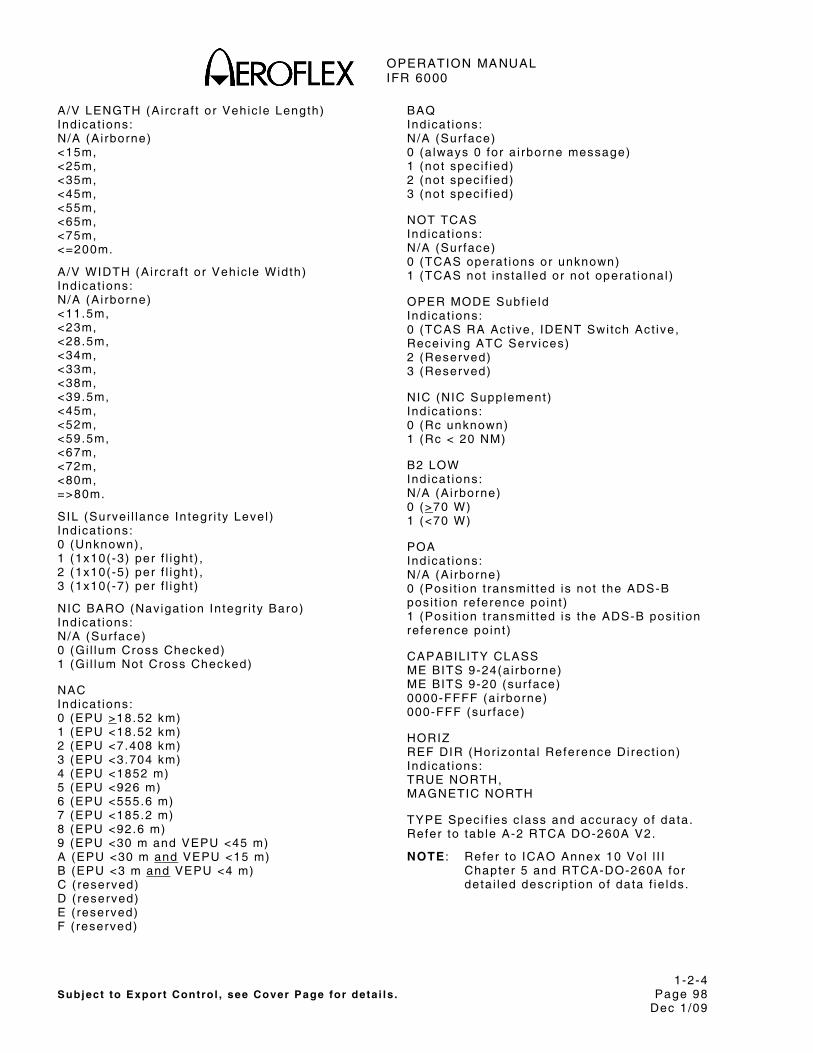
OPERATION MANUAL IFR 6000
1-2-4 Subject to Export Control , see Cover Page for deta i ls . Page 98
Dec 1/09
A/V LENGTH (Ai rcraf t or Vehic le Length) Ind icat ions: N/A (Ai rborne) <15m, <25m, <35m, <45m, <55m, <65m, <75m, <=200m.
A/V WIDTH (Ai rcraf t or Vehic le Width) Ind icat ions: N/A (Ai rborne) <11.5m, <23m, <28.5m, <34m, <33m, <38m, <39.5m, <45m, <52m, <59.5m, <67m, <72m, <80m, =>80m.
SIL (Surve i l lance In tegr i ty Level ) Ind icat ions: 0 (Unknown), 1 (1x10(-3) per f l ight ) , 2 (1x10(-5) per f l ight ) , 3 (1x10(-7) per f l ight )
NIC BARO (Navigat ion In tegr i ty Baro) Ind icat ions: N/A (Sur face) 0 (Gi l lum Cross Checked) 1 (Gi l lum Not Cross Checked)
NAC Ind icat ions: 0 (EPU >18.52 km) 1 (EPU <18.52 km) 2 (EPU <7.408 km) 3 (EPU <3.704 km) 4 (EPU <1852 m) 5 (EPU <926 m) 6 (EPU <555.6 m) 7 (EPU <185.2 m) 8 (EPU <92.6 m) 9 (EPU <30 m and VEPU <45 m) A (EPU <30 m and VEPU <15 m) B (EPU <3 m and VEPU <4 m) C ( reserved) D ( reserved) E ( reserved) F ( reserved)
BAQ Ind icat ions: N/A (Sur face) 0 (a lways 0 for a i rborne message) 1 (not spec i f ied) 2 (not spec i f ied) 3 (not spec i f ied)
NOT TCAS Ind icat ions: N/A (Sur face) 0 (TCAS operat ions or unknown) 1 (TCAS not insta l led or not operat ional )
OPER MODE Subf ie ld Ind icat ions: 0 (TCAS RA Act ive, IDENT Swi tch Act ive, Receiv ing ATC Serv ices) 2 (Reserved) 3 (Reserved)
NIC (NIC Supplement) Ind icat ions: 0 (Rc unknown) 1 (Rc < 20 NM)
B2 LOW Indicat ions: N/A (Ai rborne) 0 (>70 W) 1 (<70 W)
POA Ind icat ions: N/A (Ai rborne) 0 (Posi t ion t ransmi t ted is not the ADS-B posi t ion reference point ) 1 (Posi t ion t ransmi t ted is the ADS-B posi t ion reference point )
CAPABILITY CLASS ME BITS 9-24(a i rborne) ME BITS 9-20 (sur face) 0000-FFFF (a i rborne) 000-FFF (sur face)
HORIZ REF DIR (Hor izonta l Reference Di rect ion) Ind icat ions: TRUE NORTH, MAGNETIC NORTH
TYPE Speci f ies c lass and accuracy of data. Refer to tab le A-2 RTCA DO-260A V2.
NOTE : Refer to ICAO Annex 10 Vol l I I Chapter 5 and RTCA-DO-260A for deta i led descr ip t ion of data f ie lds.
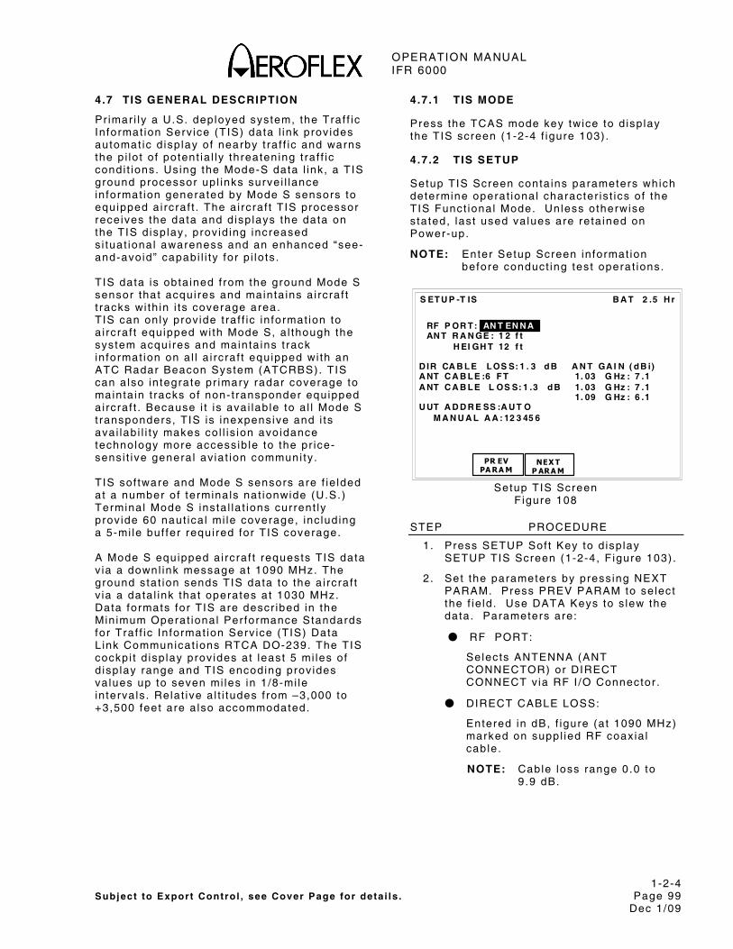
OPERATION MANUAL IFR 6000
1-2-4 Subject to Export Control , see Cover Page for deta i ls . Page 99
Dec 1/09
4.7 TIS GENERAL DESCRIPTION
Primar i ly a U.S. deployed system, the Traf f ic In format ion Serv ice (TIS) data l ink prov ides automat ic d isp lay of nearby t ra f f ic and warns the p i lo t o f potent ia l ly threatening t ra f f ic condi t ions. Us ing the Mode-S data l ink , a TIS ground processor up l inks surve i l lance in format ion generated by Mode S sensors to equipped a i rcraf t . The a i rcraf t TIS processor rece ives the data and d isp lays the data on the TIS d isp lay, prov id ing increased s i tuat ional awareness and an enhanced “see-and-avoid” capabi l i ty for p i lo ts . TIS data is obta ined f rom the ground Mode S sensor that acqui res and mainta ins a i rcraf t t racks wi th in i ts coverage area. TIS can only prov ide t ra f f ic in format ion to a i rcraf t equipped wi th Mode S, a l though the system acqui res and mainta ins t rack in format ion on a l l a i rcraf t equipped wi th an ATC Radar Beacon System (ATCRBS). TIS can a lso in tegrate pr imary radar coverage to mainta in t racks of non- t ransponder equipped a i rcraf t . Because i t is avai lab le to a l l Mode S t ransponders, TIS is inexpensive and i ts ava i lab i l i ty makes co l l is ion avo idance technology more access ib le to the pr ice-sens i t ive genera l av ia t ion communi ty . T IS sof tware and Mode S sensors are f ie lded at a number of terminals nat ionwide (U.S.) Terminal Mode S insta l la t ions current ly prov ide 60 naut ica l mi le coverage, inc lud ing a 5-mi le buf fer requi red for TIS coverage. A Mode S equipped a i rcraf t requests TIS data v ia a downl ink message at 1090 MHz. The ground stat ion sends TIS data to the a i rcraf t v ia a data l ink that operates at 1030 MHz. Data formats for TIS are descr ibed in the Min imum Operat ional Per formance Standards for Traf f ic In format ion Serv ice (TIS) Data L ink Communicat ions RTCA DO-239. The TIS cockpi t d isp lay prov ides at least 5 mi les of d isp lay range and TIS encoding prov ides va lues up to seven mi les in 1 /8-mi le in terva ls . Relat ive a l t i tudes f rom –3,000 to +3,500 feet are a lso accommodated.
4.7.1 TIS MODE
Press the TCAS mode key twice to d isp lay the TIS screen (1-2-4 f igure 103) .
4.7.2 TIS SETUP
Setup TIS Screen conta ins parameters which determine operat ional character is t ics of the TIS Funct ional Mode. Unless otherwise s tated, last used va lues are re ta ined on Power-up.
NOTE: Enter Setup Screen in format ion before conduct ing test operat ions.
B A T 2 .5 H r
PR EVPA RA M
S ET U P -T IS
NEX T P ARA M
RF P OR T : AN T EN N A AN T R A N GE : 1 2 f t H EI GH T 12 f t D IR CA B L E L OS S: 1 . 3 d B A N T GA I N ( d B i) A NT C A B L E :6 F T 1. 03 G Hz : 7 .1 A NT C A B L E L OS S: 1 .3 d B 1. 03 G Hz : 7 .1 1. 09 G Hz : 6 .1 U UT A D D R E SS :A U T O M A N U A L A A : 12 3 45 6
Setup TIS Screen F igure 108
STEP PROCEDURE
1. Press SETUP Sof t Key to d isp lay SETUP TIS Screen (1-2-4, F igure 103) .
2 . Set the parameters by press ing NEXT PARAM. Press PREV PARAM to se lect the f ie ld . Use DATA Keys to s lew the data. Parameters are:
● RF PORT:
Selects ANTENNA (ANT CONNECTOR) or DIRECT CONNECT v ia RF I /O Connector .
● DIRECT CABLE LOSS:
Entered in dB, f igure (at 1090 MHz) marked on suppl ied RF coax ia l cable.
NOTE: Cable loss range 0.0 to 9 .9 dB.

OPERATION MANUAL IFR 6000
1-2-4 Subject to Export Control , see Cover Page for deta i ls . Page 100
Dec 1/09
STEP PROCEDURE
● ANT CABLE:
Select ions USER DEFINED, 1 FT, 6 FT, 25 FT, 50 FT, 60 FT.
When USER DEFINED selected, cable loss may be manual ly entered by the user in ANT CABLE LOSS f ie ld . When 1, 6 , 25, 50 or 60 feet is se lected, ANT CABLE LOSS f ie ld is automat ica l ly ca lcu la ted.
ANT CABLE select ion of 1 , 6 , 25, 50 or 60 feet resul ts in 0 , 0 , 68, 138 and 184 ns of de lay.
● ANT CABLE LOSS:
Disp lays antenna cable loss in dB (at 1090 MHZ). I f user def ined, normal ly th is is set once, f igure marked on suppl ied RF coax ia l cab le
NOTE: Cable loss range 0.0 to 9 .9 dB.
I f preset length 1, 6 , 25, 50 or 60 feet is se lected, then cable loss in dB is automat ica l ly ca lcu la ted and d isp layed.
NOTE: Based on Aerof lex suppl ied cables, (25 and 50 foot cables opt ional )
NOTE: 25 and 50 foot cable se lect ion compensates for de lay of Aerof lex opt ional cables.
● ANT GAIN:
Entered in dBi , ga in f igures for 1030 and 1090 MHz marked on suppl ied Di rect ional Antenna.
NOTE: Cable loss range 0.0 to 20.9 dB.
● ANT RANGE:
Test Set Antenna to t ransponder antenna hor izonta l range (6 to 250) . Enter parameters for BOTTOM and TOP antenna i f ins ta l la t ion has d ivers i ty capabi l i ty .
NOTE: UNITS parameter determines feet or meters (1-2-4, F igure 11) .
STEP PROCEDURE
● ANT HEIGHT:
Test Set Antenna Range to t ransponder antenna height d i f ference (1 to 99) .
NOTE: UNITS parameter determines feet or meters (1-2-4, F igure 11) .
● UUT ADDRESS:
MANUAL or AUTO (defaul ts to AUTO on power-up) . AUTO select ion Mode S address is obta ined v ia ATCRBS/Mode S Al l Cal l (FAR Par t 43, Appendix F approved method) .
On loss of ATCRBS/Mode S Al l Cal l rep ly ( i .e . , UUT p laced in ground s tate) tests a l ready running cont inue to use last ATCRBS/ Mode S Al l Cal l obta ined address. AUTO uses manual ly entered address i f no rep ly is rece ived.
NOTE: ICAO amendment 77 t ransponders on ly rep l ies to Mode S d iscrete in ter rogat ions when insta l la t ion is in ground state.
● MANUAL ADDRESS:
A s ix d ig i t HEX address is entered i f UUT ADDRESS: MANUAL is se lected.

OPERATION MANUAL IFR 6000
1-2-4 Subject to Export Control , see Cover Page for deta i ls . Page 101
Dec 1/09
TIS TEST SCREEN
B A T 2 .5 H r
T A R G ET S : 5 U U T H DG : 1 80 d e g 1 2 3 4 5 B R G( d e g ) : 1 20 9 0 23 4 1 82 2 3 R N G( n m) : 6 . 00 4 . 00 3 .0 0 2 .0 0 1. 00 A L T ( f t ) : 35 0 0 2 0 00 1 00 0 5 00 0 A L T R A T E: C L IM B L E VE L L EV EL C L IM B L EV EL H D G( d e g ) : 2 34 1 78 5 6 2 2 0 T R A F F I C : P R OX PR O X PR O X PR O X T R F C A D D R = 3 A C4 2 1 ( 16 5 42 0 4 1) N 1 23 4 5 T S C R = 5 T SD R = 1 A L T = 12 6 70 0 f t T I S ST A T US = C ON N E CT IN G I N F O= 0 00 0
RUN T ES T
P REV P A RA M
NEX T PA RA M
T I S
T IS Operat ion Screen F igure 109
Test Screen Descr ip t ion:
TARGETS: Sets the number of s imulated targets 0 to 5.
UUT HDG: Prov ides ent ry for UUT Heading in degrees range 0 to 354. This or ientates the target bear ings wi th respect to UUT (a i rcraf t ) heading.
BRG: Sets target bear ing re la t ive to UUT (a i rcraf t ) range 0 to 354 degrees
RNG: Sets targets range re la t ive to UUT (a i rcraf t ) range 0 to 7 nm
ALT: Sets target a l t i tude re la t ive to UUT (a i rcraf t ) range +/ - 3500 f t
ALT RATE: Sets Al t i tude Rate annunciat ion on TIS d isp lay ind icat ions: CLIMB, LEVEL, DESCEND, UNUSED.
HDG: Sets target Heading
TRAFFIC: Sets target t ra f f ic s tatus on TIS d isp lay. PROX (Prox imi ty ) , TRFC (Traf f ic )
ADDR= (UUT Aircraf t Address) in HEX and (OCTAL)
TSCR= Number of TIS connect requests rece ived
TSDR= Number of TIS d isconnect requests rece ived
ALT UUT= UUT Al t i tude in f t
TIS STATUS: Ind icat ions CONNECTED (Up- l ink ing data to UUTTSCR but not up- l ink ing data to UUT)
INFO= (Debug output o f IFR 6000)
0x0001 - Reply to Data l ink Cap Repor t 0x0002 - No rep ly to Data l ink Cap Repor t 0x0004 - Reply to MSP Cap Repor t 0x0008 - No reply to MSP Cap Repor t 0x0010 - Reply to Broadcast Cap Repor t 0x0020 - No rep ly to Broadcast Cap Repor t 0x0040 - Reply to keep a l ive up l ink 0x0080 - No rep ly to keep a l ive up l ink 0x0100 - Reply to TIS upl ink 0x0200 - No rep ly to TIS upl ink Reply 0x0400 - Reply to lockout 0x0800 - No rep ly to lockout
TIS DISPLAY
Refer to 1-2-4, F igure 105. The Ai rcraf t heading is shown at the top of the d isp lay and the target headings are shown as l ines rad iat ing f rom the target symbols .
TIS Disp lay Example F igure 110
Target s ta tus:
Whi te symbol Prox imi ty
Yel low symbol Traf f ic
Relat ive a l t i tudes are d isp layed a longs ide the targets wi th ar row symbols ind icat ing c l imbing or descending. The b lue cross (bot tom center) , is the UUT Ai rcraf t .

OPERATION MANUAL IFR 6000
1-2-4 Subject to Export Control , see Cover Page for deta i ls . Page 102
Dec 1/09
TIS Operat ion F low Char t F igure 111

OPERATION MANUAL IFR 6000
1-2-4 Subject to Export Control , see Cover Page for deta i ls . Page 103
Dec 1/09
4.7 DIRECTIONAL ANTENNA USE
The Di rect ional Antenna is used three ways.
Di rect ional Antenna Mounted on Test Set F igure 112
Mount Di rect ional Antenna on f r ic t ion h inge and connect Di rect ional Antenna ANT Connector to Test Set ANT Connector v ia 12 in coax ia l cable (1-2-4, F igure 107) .
Hand Held Di rect ional Antenna F igure 113
Connect Di rect ional Antenna ANT Connector to Test Set ANT Connector v ia 72 in coaxia l cable. Point Di rect ional Antenna at UUT antenna (1-2-4, F igure 108) .
Tr ipod Mounted Di rect ional Antenna F igure 114
Connect Di rect ional Antenna ANT Connector to Test Set ANT Connector v ia 72 in coaxia l cable. Mount Di rect ional Antenna on t r ipod and point a t UUT antenna (1-2-4, F igure 109) .
XPDR:
XPDR antennas are top and bot tom mounted on a i r f rame. Ver i fy which antenna(s) is t ransponder antenna(s) as the DME antenna(s) look s imi lar .
Pos i t ion Di rect ional Antenna in d i rect s ight o f UUT antenna, avo id ing c lose obst ruct ions (such as gantr ies, ladders and too l chests etc . ) , to min imize mul t i -path re f lect ions which cause random test fa i lures.
Dis tance for test ing top UUT antenna should be suf f ic ient so UUT antenna is v is ib le (1-2-4, F igures 110 and 111) .
Shie ld wi th Antenna Shie ld (Appendix J) or d isconnect and terminate UUT Antenna not be ing tested. Deact ivate other area t ransponders or pos i t ion t ransponders at least three t imes the XPDR Setup Menu Range f rom Di rect ional Antenna.

OPERATION MANUAL IFR 6000
1-2-4 Subject to Export Control , see Cover Page for deta i ls . Page 104
Dec 1/09
Procedure to Avoid False TCAS RA’s on Overf lying Aircraft or Alt i tude:
I f the a i rc raf t barometr ic system is a t a l t i tude, sh ie ld UUT Antenna being tested wi th Antenna Shie ld (Appendix J) . Shie ld wi th another Antenna Shie ld or d isconnect and terminate UUT Antenna(s) not be ing tested. Deact ivate other area t ransponders or pos i t ion t ransponder >50 f t (15.24 m) f rom the Di rect ional Antenna. Pos i t ion Di rect ional Antenna ≤20 f t (6 .1 m) f rom UUT Antenna being tested.
DME:
DME Antennas are bot tom mounted on a i r f rame. Ver i fy which antenna(s) is DME Antenna(s) as the t ransponder lower antenna(s) look s imi lar .
Pos i t ion Di rect ional Antenna in d i rect s ight o f UUT antenna, avo id ing c lose obst ruct ions (such as gantr ies, ladders and too l chests etc . ) , to min imize mul t ipath re f lect ions which cause random test fa i lures. Usual d is tance f rom UUT antenna is approx imate ly 10 to 20 feet .
NOTE: Direct ional Antenna should not be pos i t ioned c loser than 6 feet , to ensure that the antenna far f ie ld is tested
TCAS:
Most TCAS insta l la t ions have top and bot tom d i rect ional antennas. Some a i rcraf t are f i t ted wi th an omni-d i rect ional bot tom antenna.
Fol low Avoid False TCAS RA’s on Over f ly ing Ai rcraf t or A l t i tude procedure.
Posi t ion the Test Set Di rect ional Antenna in d i rect s ight o f UUT antenna. To min imize in t ruder bear ing error , Test Set antenna should be at the same height as the UUT antenna. Refer to 1-2-4, F igure 105 to ensure Test Set Di rect ional Antenna is wi th in ef fect ive coverage area for e i ther ATCRBS or Mode S.
Avoid c lose obst ruct ions (such as gantr ies, ladders and too l chests) to min imize mul t ipath re f lect ions which cause erroneous in t ruder bear ings.
Test ing in a i rcraf t hangers may resul t in er rat ic bear ing of s imulated in t ruder . Changing bear ing may resul t in a more re l iab le t rack. When test ing top antenna in a hanger use a gantry a t the same height as the top antenna.
Mode S Coverage Wi th in 12 nmi S imulated Range
Figure 115
Refer to 1-2-4, F igure 110. Due to h igh power densi ty reduct ion in some TCAS in ter rogators , Mode S ef fect ive coverage d is tance may be dependent on the Test Set s imulated range. For those uni ts p lace Test Set accord ing to 1-2-4, F igure 111. For s imulated ranges wi th in 1 nm, pos i t ion test set wi th in 30 f t (9 .0 m) of UUT antenna.
TCAS 6000 Ef fect ive Test Coverage F igure 116

OPERATION MANUAL IFR 6000
1-2-4 Subject to Export Control , see Cover Page for deta i ls . Page 105
Dec 1/09
AIRCRAFTWITH UUTBUILDING
BUILDING
TEST SETWITH ANTENNA
FOR OPTIMUM PERFORMANCE:BUILDINGS, VEHICLES AND OTHERAIRCRAFT SHOULD BE LOCATED AT RIGHT ANGLES TO OR BEHIND ANTENNA.
FOR ACCEPTABLE PERFORMANCE:OTHER AIRCRAFT SHOULD BE >3XDISTANCE FROM TEST SET. BUILDINGSSHOULD BE AT OBLIQUE ANGLES
20 OF BEAMWIDTH.
05817A
ANTENNA
BEAMWIDTH
± VERTICALHORIZONTAL
PATTERNHANDLE
TNC CONNECTOR
6’ CABLE TOTEST SET
MULTIPATH
MULTIP
ATH
X
FLAT ANTENNA
≈20
OCCUPYING <
25±
Suggested Layout to Reduce Mul t ipath Errors F igure 117
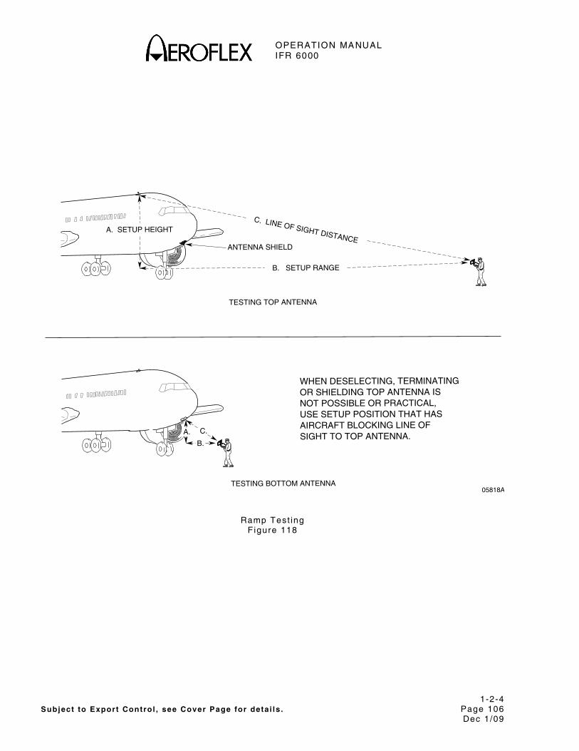
OPERATION MANUAL IFR 6000
1-2-4 Subject to Export Control , see Cover Page for deta i ls . Page 106
Dec 1/09
C. LINE OF SIGHT DISTANCEANTENNA SHIELD
TESTING BOTTOM ANTENNA
TESTING TOP ANTENNA
AIRCRAFT BLOCKING LINE OFUSE SETUP POSITION THAT HASNOT POSSIBLE OR PRACTICAL,OR SHIELDING TOP ANTENNA ISWHEN DESELECTING, TERMINATING
B. SETUP RANGE
A. SETUP HEIGHT
B.
A. C.SIGHT TO TOP ANTENNA.
05818A
Ramp Test ing F igure 118
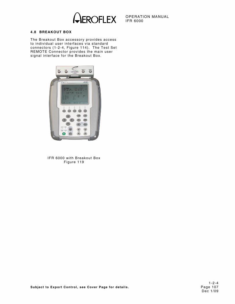
OPERATION MANUAL IFR 6000
1-2-4 Subject to Export Control , see Cover Page for deta i ls . Page 107
Dec 1/09
4.8 BREAKOUT BOX
The Breakout Box accessory prov ides access to ind iv idual user in ter faces v ia s tandard connectors (1-2-4, F igure 114) . The Test Set REMOTE Connector prov ides the main user s ignal in ter face for the Breakout Box.
IFR 6000 wi th Breakout Box F igure 119

OPERATION MANUAL IFR 6000
1-2-4 Subject to Export Control , see Cover Page for deta i ls . Page 108
Dec 1/09
THIS PAGE INTENTIONALLY LEFT BLANK.

OPERATION MANUAL IFR 6000
1-3-1 Subject to Export Control , see Cover Page for deta i ls . Page 1
Dec 1/09
SECTION 3 - SPECIFICATIONS
NOTE: A 5 minute warm-up per iod is requi red for a l l spec i f icat ions.
NOTE: Speci f icat ions are subjec t to change wi thout not ice.
DME MODE SIGNAL GENERATOR
Output Frequency:
Reply Frequency:
Range: 962 to 1213 MHz
Accuracy: ±10 kHz
Output Level:
ANT Connector :
Range: -67 to -2 dBm at ANT Connector
Resolut ion: 1 dB
Accuracy: ±2 dB
Dis tance to UUT Antenna: 6 to 300 f t wi th suppl ied antenna
RF I /O Connector :
Range: -115 to -47 dBm
Resolut ion: 1 dB
Accuracy:
-95 to -47 dBm: ±1 dB
-115 to <-95 dBm: ±2 dB
Reply Pulse Spacing:
P1 to P2: 12 μs (±100 ns) (X Channel ) a t 50% peak
P1 to P2: 30 μs (±100 ns) (Y Channel ) a t 50% peak
Reply Pulse Width:
P1/P2: 3 .5 μs (±0.5 μs)
Echo Reply:
Contro l : On/Of f
Pos i t ion: 30 nmi (±1 nmi)
Ampl i tude: -11 dB (±1 dB) re la t ive to rep ly leve l

OPERATION MANUAL IFR 6000
1-3-1 Subject to Export Control , see Cover Page for deta i ls . Page 2
Dec 1/09
DME MODE SIGNAL GENERATOR (cont)
Reply Pulse Rise and Fal l Times:
A l l Pulses:
Rise T ime: 2 .5 μs (±0.25 μs) (10% to 90%)
Fa l l T ime: 2 .5 μs (±0.25 μs) (90% to 10%)
Reply Delay:
X Channel :
F ixed Reply Delay: 50 μs (±100 ns)
Y Channel :
F ixed Reply Delay: 56 μs (±100 ns)
Range Delay:
X and Y Channel :
Range: 0 to 450.00 nmi
Resolut ion: 0 .01 nmi
Accuracy: ±0.01 nmi
Range Rate:
X and Y Channel :
Range: 10 to 6500 k ts
Resolut ion: 1 k ts
Accuracy: ±0.01 % typ ica l , tested to ±0.5%
Squitter:
PRF: 2700 Hz
Accuracy: ±2%
Dis t r ibut ion: Per ARINC 568
Reply Eff ic iency:
Range: 0 to 100%
Resolut ion: 1% increments
Accuracy: ±0.5%
Ident Tone:
Select ion: Selectable three le t ter code
Frequency: 1350 Hz
Accuracy: ±2 Hz

OPERATION MANUAL IFR 6000
1-3-1 Subject to Export Control , see Cover Page for deta i ls . Page 3
Dec 1/09
DME MODE UUT MEASUREMENTS
ERP:
Range: +47 to +64 dBm
Resolut ion: 0 .1 dB
Accuracy: ±2 dB
Direct Connection Peak Pulse Power:
Range: +47 to +64 dBm
Resolut ion: 0 .1 dB
Accuracy: ±1 dB
Frequency:
Range: 1025.00 to 1150.00 MHz
Resolut ion: 10 kHz
Accuracy: ±20 kHz
Interrogat ion Pulse Width:
P1 and P2 Pulse Widths:
Range: 2 .00 to 5.00 μs
Resolut ion: 1 ns
Accuracy: ±50 ns
Interrogat ion Pulse Spacing:
P1 to P2 Spacing: 10 to 14 μs (X Channel ) 34 to 38 μs (Y Channel )
Resolut ion: 10 ns
Accuracy: ±20 ns
Interrogation PRF:
Range: 1 to 300 Hz
Resolut ion: 1 Hz
Accuracy: ±2 Hz

OPERATION MANUAL IFR 6000
1-3-1 Subject to Export Control , see Cover Page for deta i ls . Page 4
Dec 1/09
TRANSPONDER MODE SIGNAL GENERATOR
RF Output Frequency:
In ter rogat ion Frequency: 1030 MHz
Accuracy: ±10 kHz
RF Output Level:
Ant Connector : MTL +6 dB typ ica l , automat ica l ly cont ro l led for a MTL range of -83 to -68 dBm
Range: -67 to -2 dBm at ANT Connector
Resolut ion: 0 .5 dB
Accuracy: ±2 dB
Dis tance to UUT Antenna: 6 to 200 f t wi th suppl ied antenna
RF I /O Connector : MTL + 6 dB typ ica l , automat ica l ly cont ro l led
Range: -115 to -47 dBm
Resolut ion: 0 .5 dB
Accuracy:
-95 to -47 dBm: ±1 dB
-115 to <-95 dBm: ±2 dB
ATCRBS/Mode S Interrogation Pulse Spacing:
Mode A:
P1 to P2: 2 .00 μs (±25 ns)
P1 to P3: 8 .00 μs (±25 ns)
Mode C:
P1 to P2: 2 .00 μs (±25 ns)
P1 to P3: 21.00 μs (±25 ns)
Mode S:
P1 to P2: 2 .00 μs (±25 ns)
P1 to P6: 3 .50 μs (±25 ns)
P1 to SPR: 4.75 μs (±25 ns)
P5 to SPR: 0.40 μs (±50 ns)
Intermode Interrogat ion Pulse Spacing:
Mode A:
P1 to P3: 8 .00 μs (±25 ns)
P1 to P4: 10.00 μs (±25 ns)
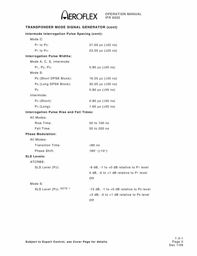
OPERATION MANUAL IFR 6000
1-3-1 Subject to Export Control , see Cover Page for deta i ls . Page 5
Dec 1/09
TRANSPONDER MODE SIGNAL GENERATOR (cont)
Intermode Interrogat ion Pulse Spacing (cont):
Mode C:
P1 to P3: 21.00 μs (±25 ns)
P1 to P4: 23.00 μs (±25 ns)
Interrogat ion Pulse Widths:
Mode A, C, S, In termode:
P1, P2, P3: 0 .80 μs (±50 ns)
Mode S:
P6 (Shor t DPSK Block) : 16.25 μs (±50 ns)
P6 (Long DPSK Block) : 30.25 μs (±50 ns)
P5 0 .80 μs (±50 ns)
In termode:
P4 (Shor t ) : 0 .80 μs (±50 ns)
P4 (Long) : 1 .60 μs (±50 ns)
Interrogat ion Pulse Rise and Fal l Times:
A l l Modes:
Rise T ime: 50 to 100 ns
Fa l l T ime: 50 to 200 ns
Phase Modulat ion:
A l l Modes:
Trans i t ion T ime: ≤80 ns
Phase Shi f t : 180° (±10° )
SLS Levels:
ATCRBS:
SLS Level (P2) : -9 dB, -1 to +0 dB re lat ive to P1 leve l
0 dB, -0 to +1 dB re la t ive to P1 leve l
Of f
Mode S:
SLS Level (P5) : NOTE 1 -12 dB, -1 to +0 dB re la t ive to P6 leve l
+3 dB, -0 to +1 dB re la t ive to P6 leve l
Of f

OPERATION MANUAL IFR 6000
1-3-1 Subject to Export Control , see Cover Page for deta i ls . Page 6
Dec 1/09
TRANSPONDER MODE SIGNAL GENERATOR (cont)
Interrogat ion Test Signals:
Mode S:
PRF: 50 Hz (±5 Hz)
ATCRBS:
PRF: 235 Hz (±5 Hz)

OPERATION MANUAL IFR 6000
1-3-1 Subject to Export Control , see Cover Page for deta i ls . Page 7
Dec 1/09
TRANSPONDER MODE UUT MEASUREMENTS
ERP (at 1090 MHz):
Range: +45.5 to +59 dBm (35.5 to 800 W)
Resolut ion: 0 .1 dB
Accuracy: ±2 dB
Direct Connection Peak Pulse Power (at 1090 MHz) :
Range: +46.5 to +59 dBm (45 to 800 W)
Resolut ion: 0 .1 dB
Accuracy: ±1 dB
Transmitter Frequency:
Range: 1087.000 to 1093.000 MHz
Resolut ion: 10 kHz
Accuracy: ±50 kHz
Receiver Sensit iv i ty, Radiated MTL:
Range: -79 to -67 dBm into 0 dBi antenna
Resolut ion: 0 .1 dB
Accuracy: ±2 dB, typ ica l
Receiver Sensit iv i ty, Direct Connect ion MTL:
Range: -79 to -67 dBm
Resolut ion: 0 .1 dB
Accuracy: ±2 dB
Reply Delay:
ATCRBS:
Range: 1 .80 to 7.00 μs
Resolut ion: 10 ns
Accuracy: ±50 ns
Mode S and ATCRBS Mode S Al l -Cal l :
Range: 125.00 to 131.00 μs
Resolut ion: 10 ns
Accuracy: ±50 ns

OPERATION MANUAL IFR 6000
1-3-1 Subject to Export Control , see Cover Page for deta i ls . Page 8
Dec 1/09
TRANSPONDER MODE UUT MEASUREMENTS (cont)
Reply Delay Ji t ter:
ATCRBS:
Range: 0 .00 to 2.30 μs
Resolut ion: 1 ns
Accuracy: ±20 ns
Mode S and ATCRBS Mode S Al l -Cal l :
Range: 0 .00 to 6.00 μs
Resolut ion: 1 ns
Accuracy: ±20 ns
Pulse Spacing:
F1 to F2:
Range: 19.70 to 21.60 μs
Resolut ion: 1 ns
Accuracy: ±20 ns
Mode S Preamble:
Range:
P1 to P2: 0 .8 to 1.2 μs
P1 to P3: 3 .3 to 3.7 μs
P1 to P4: 4 .3 to 4.7 μs
Resolut ion: 1 ns
Accuracy: ±20 ns
Pulse Widths:
F1 and F2:
Range: 0 .25 to 0.75 μs
Resolut ion: 1 ns
Accuracy: ±20 ns
Mode S Preamble:
Range: 0 .25 to 0.75 μs
Resolut ion: 1 ns
Accuracy: ±20 ns

OPERATION MANUAL IFR 6000
1-3-1 Subject to Export Control , see Cover Page for deta i ls . Page 9
Dec 1/09
TRANSPONDER MODE UUT MEASUREMENTS (cont)
Pulse Ampli tude Variat ion:
Range:
Mode S (Relat ive to P1) : -3 to +3 dB
ATCRBS (Relat ive to F1) : -3 to +3 dB
Resolut ion: 0 .1 dB, (0 .01 dB v ia RCI)
Accuracy: ±0.5 dB
DF 11 Squit ter Period:
Range: 0 .10 to 4.88 sec
Resolut ion: 10 ms
Accuracy: ±10 ms
Diversi ty Isolat ion:
Range: 0 to >20 dB (Depending on Test Dis tance)
Test Dis tance is 1 .83 m (6 f t ) to 28.96 m (95 f t )
Resolut ion: 0 .1 dB
Accuracy: ±3 dB
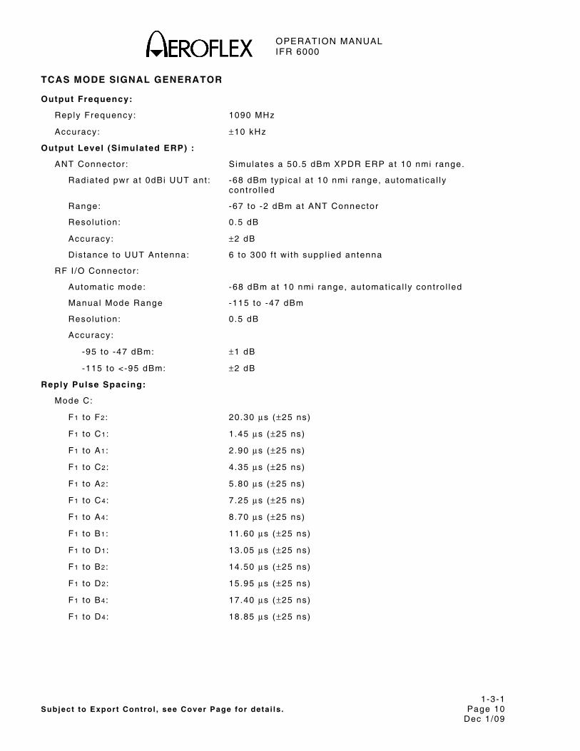
OPERATION MANUAL IFR 6000
1-3-1 Subject to Export Control , see Cover Page for deta i ls . Page 10
Dec 1/09
TCAS MODE SIGNAL GENERATOR
Output Frequency:
Reply Frequency: 1090 MHz
Accuracy: ±10 kHz
Output Level (Simulated ERP) :
ANT Connector : S imulates a 50.5 dBm XPDR ERP at 10 nmi range.
Radiated pwr at 0dBi UUT ant : -68 dBm typ ica l a t 10 nmi range, automat ica l ly cont ro l led
Range: -67 to -2 dBm at ANT Connector
Resolut ion: 0 .5 dB
Accuracy: ±2 dB
Dis tance to UUT Antenna: 6 to 300 f t wi th suppl ied antenna
RF I /O Connector :
Automat ic mode: -68 dBm at 10 nmi range, automat ica l ly cont ro l led
Manual Mode Range -115 to -47 dBm
Resolut ion: 0 .5 dB
Accuracy:
-95 to -47 dBm: ±1 dB
-115 to <-95 dBm: ±2 dB
Reply Pulse Spacing:
Mode C:
F1 to F2: 20.30 μs (±25 ns)
F1 to C1: 1 .45 μs (±25 ns)
F1 to A1: 2 .90 μs (±25 ns)
F1 to C2: 4 .35 μs (±25 ns)
F1 to A2: 5 .80 μs (±25 ns)
F1 to C4: 7 .25 μs (±25 ns)
F1 to A4: 8 .70 μs (±25 ns)
F1 to B1: 11.60 μs (±25 ns)
F1 to D1: 13.05 μs (±25 ns)
F1 to B2: 14.50 μs (±25 ns)
F1 to D2: 15.95 μs (±25 ns)
F1 to B4: 17.40 μs (±25 ns)
F1 to D4: 18.85 μs (±25 ns)

OPERATION MANUAL IFR 6000
1-3-1 Subject to Export Control , see Cover Page for deta i ls . Page 11
Dec 1/09
TCAS MODE SIGNAL GENERATOR (cont)
Reply Pulse Spacing (cont):
Mode S:
P1 to P2 : 1 .00 μs (±25 ns)
P1 to P3 : 3 .50 μs (±25 ns)
P1 to P4 : 4 .50 μs (±25 ns)
P1 to D1: 8 .00 μs (±25 ns)
D1 to Dn (n = 2 to 112) : 1 .00 μs t imes (n-1) (±25 ns)
Reply Pulse Widths:
Mode C:
A l l Pulses : 0 .45 μs (±50 ns)
Mode S:
P1 through P4: 0 .50 μs (±50 ns)
D1 through D112 : 0 .50 μs (±50 ns) , 1 μs ch ip width
Reply Modes: TCAS I / I I Mode C (wi th a l t i tude repor t ing)
TCAS I I Mode S formats 0, 11, 16
Reply Pulse Ampli tudes:
ATCRBS: ±1 dB re la t ive to F1
Mode S: ±1 dB re la t ive to P1
Reply Pulse Rise and Fal l Times:
A l l Modes :
Rise T ime: 50 to 100 ns
Fa l l T ime: 50 to 200 ns
Percent Reply :
Range: 0 to 100%
Resolut ion: 10%
Accuracy: ±1%
Reply Delay
ATCRBS: 3.0 μs (±50 ns)
Mode S: 128 μs (±50 ns)
Range Delay:
Range: 0 to 260 nmi
Resolut ion: 0 .1 nmi
Accuracy: ±0.02 nmi
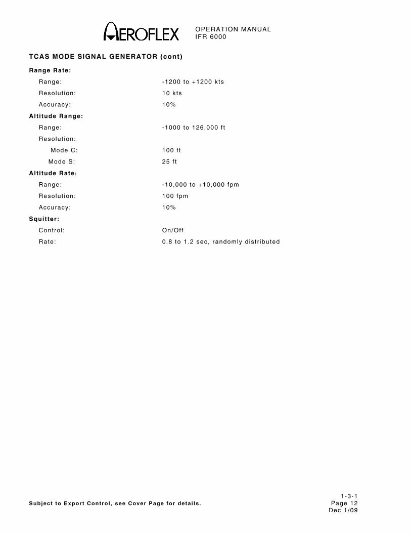
OPERATION MANUAL IFR 6000
1-3-1 Subject to Export Control , see Cover Page for deta i ls . Page 12
Dec 1/09
TCAS MODE SIGNAL GENERATOR (cont)
Range Rate:
Range: -1200 to +1200 k ts
Resolut ion: 10 k ts
Accuracy: 10%
Alt i tude Range:
Range: -1000 to 126,000 f t
Resolut ion:
Mode C: 100 f t
Mode S: 25 f t
Alt i tude Rate:
Range: -10,000 to +10,000 fpm
Resolut ion: 100 fpm
Accuracy: 10%
Squitter:
Contro l : On/Of f
Rate: 0 .8 to 1.2 sec, randomly d is t r ibuted
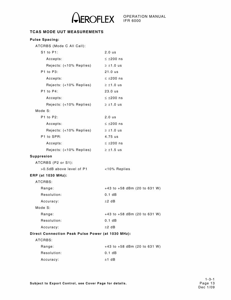
OPERATION MANUAL IFR 6000
1-3-1 Subject to Export Control , see Cover Page for deta i ls . Page 13
Dec 1/09
TCAS MODE UUT MEASUREMENTS
Pulse Spacing:
ATCRBS (Mode C Al l Cal l ) :
S1 to P1: 2 .0 us
Accepts : ≤ ±200 ns
Rejects : (<10% Repl ies) ≥ ±1.0 us
P1 to P3: 21.0 us
Accepts : ≤ ±200 ns
Rejects : (<10% Repl ies) ≥ ±1.0 us
P1 to P4: 23.0 us
Accepts : ≤ ±200 ns
Rejects : (<10% Repl ies) ≥ ±1.0 us
Mode S:
P1 to P2: 2 .0 us
Accepts : ≤ ±200 ns
Rejects : (<10% Repl ies) ≥ ±1.0 us
P1 to SPR: 4.75 us
Accepts : ≤ ±200 ns
Rejects : (<10% Repl ies) ≥ ±1.5 us
Suppresion
ATCRBS (P2 or S1) :
>0.5dB above leve l o f P1 <10% Repl ies
ERP (at 1030 MHz):
ATCRBS:
Range: +43 to +58 dBm (20 to 631 W)
Resolut ion: 0 .1 dB
Accuracy: ±2 dB
Mode S:
Range: +43 to +58 dBm (20 to 631 W)
Resolut ion: 0 .1 dB
Accuracy: ±2 dB
Direct Connection Peak Pulse Power (at 1030 MHz):
ATCRBS:
Range: +43 to +58 dBm (20 to 631 W)
Resolut ion: 0 .1 dB
Accuracy: ±1 dB
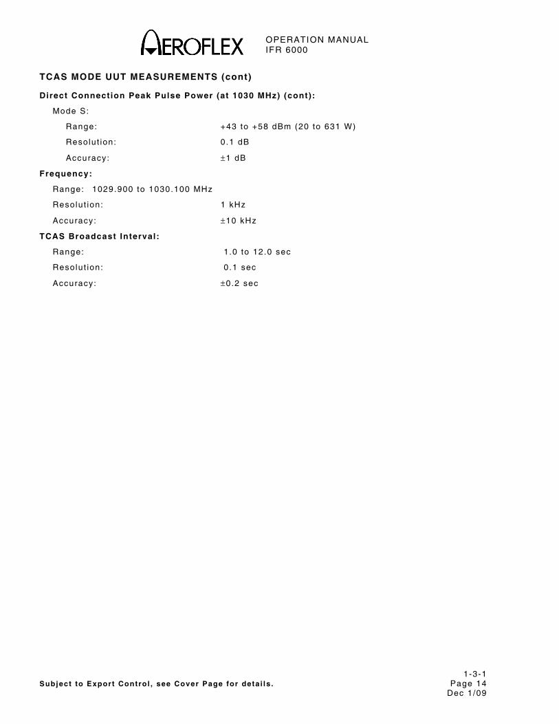
OPERATION MANUAL IFR 6000
1-3-1 Subject to Export Control , see Cover Page for deta i ls . Page 14
Dec 1/09
TCAS MODE UUT MEASUREMENTS (cont)
Direct Connection Peak Pulse Power (at 1030 MHz) (cont):
Mode S:
Range: +43 to +58 dBm (20 to 631 W)
Resolut ion: 0 .1 dB
Accuracy: ±1 dB
Frequency:
Range: 1029.900 to 1030.100 MHz
Resolut ion: 1 kHz
Accuracy: ±10 kHz
TCAS Broadcast Interval:
Range: 1 .0 to 12.0 sec
Resolut ion: 0 .1 sec
Accuracy: ±0.2 sec

OPERATION MANUAL IFR 6000
1-3-1 Subject to Export Control , see Cover Page for deta i ls . Page 15
Dec 1/09
MISCELLANEOUS
Inputs/Outputs:
RF I /O:
Type: Input /Output
Impedance: 50 Ω typ ica l
Maximum Input Level : 4 kW peak
10 W average
VSWR: <1.3:1
Antenna:
Type: Input /Output
Impedance: 50 Ω typ ica l
Maximum Input Level : 10 W peak
1 /2 W average
V ideo
Type: Output
Impedance: 50 Ω typ ica l
Generate Video Level : 1 .1 ± 0 .4V peak in to 50 Ω
Receive Video Level : Propor t ional to IF leve l
Test Antenna:
VSWR: <1.5:1
Gain: 6 dB, Typica l
Time Base (TCXO):
Temperature Stabi l i ty : ±1 ppm
Aging: ±1 ppm per year
Accuracy: ±1 ppm
Test L imi t : ±0.3 ppm
Battery:
Type: L i Ion
Durat ion: >4 hrs cont inuous operat ion
>6 hrs , Typica l
Input Power (Test Set) :
Input Range: 11 to 32 Vdc
Power Consumpt ion: 55 W Maximum
16 W Nominal a t 18 Vdc wi th charged bat tery
Fuse Requi rements: 5 A, 32 Vdc, Type F

OPERATION MANUAL IFR 6000
1-3-1 Subject to Export Control , see Cover Page for deta i ls . Page 16
Dec 1/09
MISCELLANEOUS (cont)
Input Power (Suppl ied External AC to DC Converter):
Input Range: 100 to 250 VAC, 1.5 A Max, 47 to 63 Hz
Mains Supply Vol tage F luctuat ions: ≤10% of the nominal vo l tage
Trans ient Overvo l tages: Accord ing to Insta l la t ion Category I I
Environmental (Test Set) :
Use: Pol lu t ion Degree 2
A l t i tude: ≤4800 m
Operat ing Temperature: -20°C to 55°C NOTE 2
Storage Temperature: -30°C to 71°C NOTE 3
Relat ive Humid i ty : 95% (±5%) f rom 5°C to 30°C 75% (±5%) f rom 30°C to 40°C 45% (±5%) f rom 40°C to 55°C
Environmental (Suppl ied External AC to DC Converter):
Use: Indoors
A l t i tude: ≤10,000 m
Operat ing Temperature: 0°C to 40°C
Storage Temperature: -20°C to 71°C
Physical Characterist ics:
Dimensions:
Height : 11.2 in (28.5 cm)
Width: 9 .1 in (23.1 cm)
Depth: 2 .7 in (6 .9 cm)
Weight (Test Set on ly) : <8 lbs. (3 .6 kg)

OPERATION MANUAL IFR 6000
1-3-1 Subject to Export Control , see Cover Page for deta i ls . Page 17
Dec 1/09
SUPPLEMENTAL INFORMATION:
Test Set Cert i f icat ions:
A l t i tude, Operat ing: MIL-PRF-28800F, Class 2
A l t i tude, Non-Operat ing: MIL-PRF-28800F, Class 2
Bench Handl ing: MIL-PRF-28800F, Class 2
B lowing Dust MIL STD -810F, Method 510.4, Procedure 1
Dr ip Proof : MIL-PRF-28800F, Class 2
Explos ive Atmosphere: MIL-STD-810F, Method 511.4, Procedure 1
Relat ive Humid i ty : MIL-PRF-28800F, Class 2
Shock, Funct ional : MIL-PRF-28800F, Class 2
V ibrat ion L imi ts : MIL-PRF-28800F, Class 2
Temperature, Operat ing: MIL-PRF-28800F, Class 2 NOTE 4
Temp, Non-Operat ing: MIL-PRF-28800F, Class 2 NOTE 5
Trans i t Drop: MIL-PRF-28800F, Class 2
Safety Compl iance: UL-61010B-1 EN 61010-1 CSA 22.2 No 61010-1
EMC: EN 61326
External AC-DC Converter Cert i f icat ions:
Safety Compl iance: UL 1950 DS
CSA 22.2 No. 234
VDE EN 60 950
EMI/RFI Compl iance: FCC Docket 20780, Curve “B”
EMC: EN 61326
Transit Case Cert i f icat ions:
Drop Test : FED-STD-101C, Method 5007.1, Paragraph 6.3, Procedure A, Level A
Fa l l ing Dar t Impact : ATA 300, Category I
V ibrat ion, Loose Cargo: FED-STD-101C, Method 5019
V ibrat ion, Sweep: ATA 300, Category I
S imulated Rainfa l l : MIL-STD-810F, Method 506.4, Procedure I I o f 4 .1.2
FED-STD-101C, Method 5009.1, Sec 6.7.1
Immers ion: MIL-STD-810F, Method 512.4

OPERATION MANUAL IFR 6000
1-3-1 Subject to Export Control , see Cover Page for deta i ls . Page 18
Dec 1/09
NOTES
NOTE 1 SLS leve l is automat ica l ly contro l led in the SLS LEVEL test .
NOTE 2 Bat tery charg ing temperature range is 5° to 40°C (contro l led by in ternal charger) .
NOTE 3 L i Ion Bat tery must be removed below -20° C and above 60° C.
NOTE 4 Temperature range extended to -20°C to 55°C.
NOTE 5 Temperature range reduced to -30°C to 71°C.
OPERATION MANUAL IFR 6000
1-4-1 Subject to Export Control , see Cover Page for deta i ls . Page 1 Dec 1/09
SECTION 4 - SHIPPING
1. SHIPPING TEST SETS
Aerof lex Test Sets re turned to factory for ca l ibrat ion, serv ice or repai r must be repackaged and sh ipped accord ing to the fo l lowing condi t ions:
Authorizat ion
Do not re turn any products to factory wi thout f i rs t receiv ing author izat ion f rom Aerof lex Customer Serv ice Depar tment .
Contact Aerof lex:
Customer Serv ice Dept .
Te lephone: (800) 835-2350 FAX: (316) 524-5330
E-Mai l : amer icas.serv ice@aerof lex.com
Tagging Test Sets
Al l Test Sets must be tagged wi th :
● Ident i f icat ion and address of owner
● Nature of serv ice or repai r requi red
● Model Number
● Ser ia l Number
Shipping Containers
Test Sets must be repackaged in or ig ina l sh ipp ing conta iners us ing Aerof lex pack ing molds. I f or ig ina l sh ipp ing conta iners and mater ia ls are not avai lab le , contact Aerof lex Customer Serv ice for sh ipp ing inst ruct ions.
Freight Costs
All f reight costs on non-warranty shipments are assumed by the customer. (See “Warranty Packet” for freight charge pol icy on warranty c laims.)
Freight Insurance
Aerof lex recommends that customers obta in f re ight insurance wi th the f re ight carr ier when sh ipp ing Test Set . Aerof lex is not responsib le for cost o f repai rs for damages that occur dur ing sh ipment on warranty or non-warranty i tems. Contact Aerof lex Customer Serv ice for Test Set sh ipp ing inst ruct ions.
NOTE: Test Set must be proper ly packaged or f re ight company may not honor insurance c la im.

OPERATION MANUAL IFR 6000
1-4-1 Subject to Export Control , see Cover Page for deta i ls Page 2 Dec 1/09
1.2 REPACKING PROCEDURE
● Make sure bot tom pack ing mold is seated on f loor o f sh ipp ing conta iner .
● Carefu l ly wrap Test Set wi th po lyethy lene sheet ing to protect f in ish.
● P lace Test Set in to sh ipp ing conta iner , making sure Test Set is secure ly seated in bot tom pack ing mold.
● P lace top pack ing mold over top of Test Set and press down unt i l top pack ing mold rests so l id ly on Test Set .
● Close sh ipp ing conta iner l ids and seal wi th sh ipp ing tape or an indust r ia l s tap ler . T ie a l l s ides of conta iner wi th break res is tant rope, twine or equiva lent .
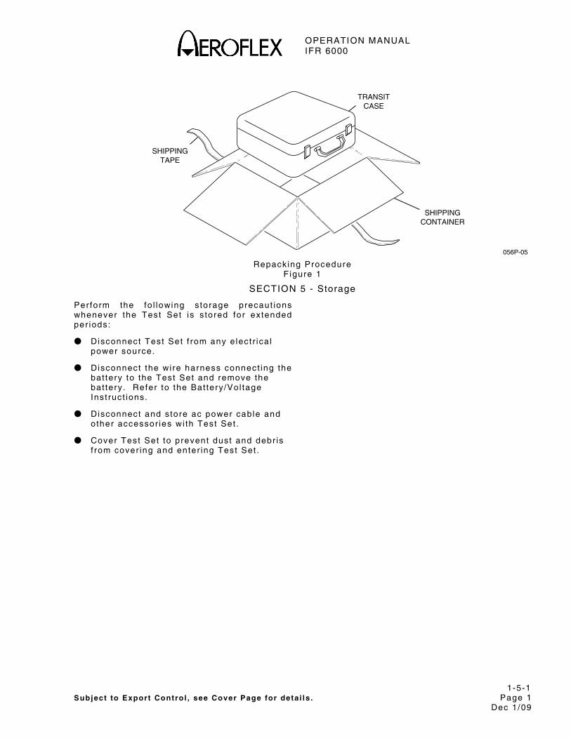
OPERATION MANUAL IFR 6000
1-5-1 Subject to Export Control , see Cover Page for deta i ls . Page 1 Dec 1/09
056P-05
TAPESHIPPING
CONTAINERSHIPPING
CASETRANSIT
Repacking Procedure
F igure 1
SECTION 5 - Storage
Perform the fo l lowing s torage precaut ions whenever the Test Set is s tored for extended per iods:
● Disconnect Test Set f rom any e lect r ica l power source.
● Disconnect the wi re harness connect ing the bat tery to the Test Set and remove the bat tery . Refer to the Bat tery /Vol tage Inst ruct ions.
● Disconnect and s tore ac power cable and other accessor ies wi th Test Set .
● Cover Test Set to prevent dust and debr is f rom cover ing and enter ing Test Set .

OPERATION MANUAL IFR 6000
1-5-1 Subject to Export Control , see Cover Page for deta i ls . Page 2 Dec 1/09
THIS PAGE INTENTIONALLY LEFT BLANK.
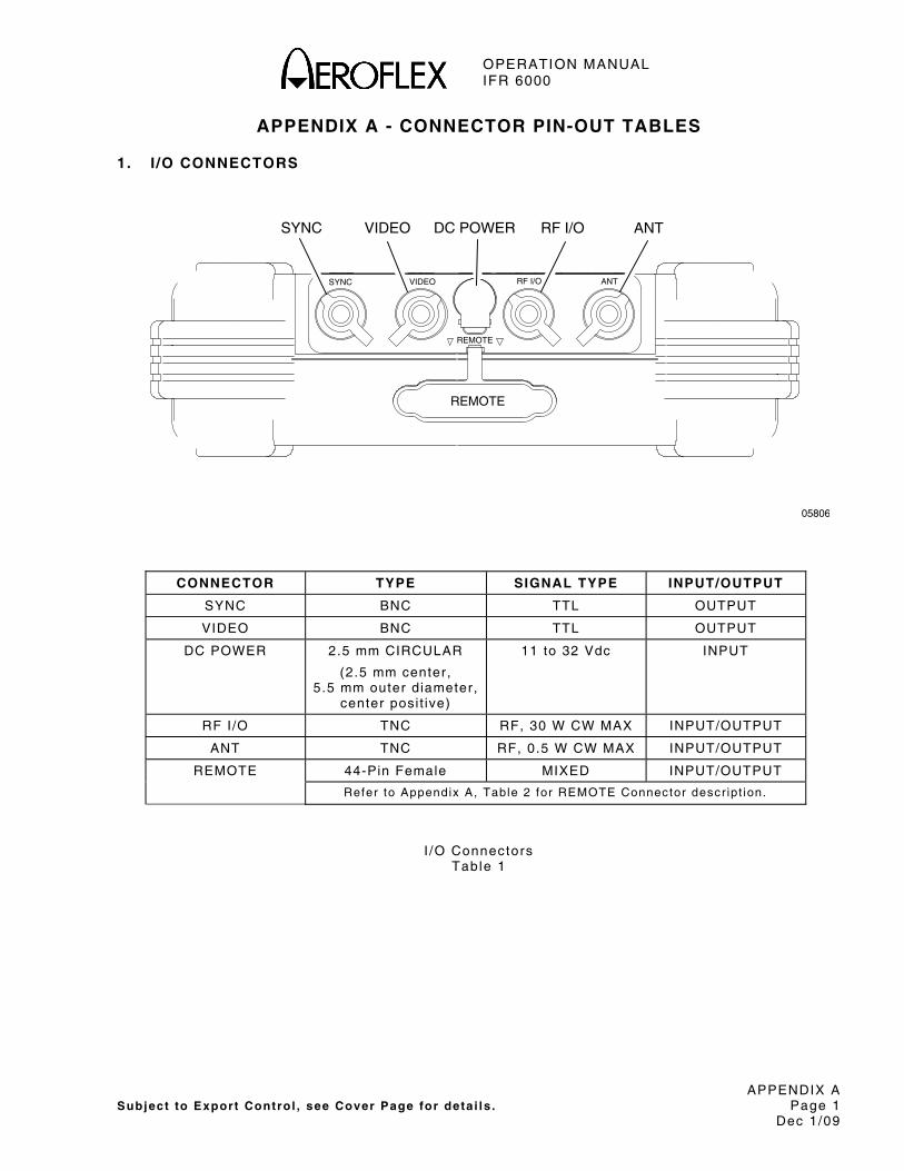
OPERATION MANUAL IFR 6000
APPENDIX A Subject to Export Control , see Cover Page for deta i ls . Page 1
Dec 1/09
APPENDIX A - CONNECTOR PIN-OUT TABLES
1. I /O CONNECTORS
REMOTE
SYNC VIDEO
REMOTE
RF I/O ANT
05806
SYNC VIDEO DC POWER ANTRF I/O
CONNECTOR TYPE SIGNAL TYPE INPUT/OUTPUT
SYNC BNC TTL OUTPUT
VIDEO BNC TTL OUTPUT
DC POWER 2.5 mm CIRCULAR
(2.5 mm center, 5.5 mm outer diameter,
center posi t ive)
11 to 32 Vdc INPUT
RF I/O TNC RF, 30 W CW MAX INPUT/OUTPUT
ANT TNC RF, 0.5 W CW MAX INPUT/OUTPUT
REMOTE 44-Pin Female MIXED INPUT/OUTPUT
Refer to Appendix A, Table 2 for REMOTE Connector descr ipt ion.
I /O Connectors Table 1

OPERATION MANUAL IFR 6000
APPENDIX A Subject to Export Control , see Cover Page for deta i ls . Page 2
Dec 1/09
2. REMOTE CONNECTOR PIN-OUT TABLE
05807
15 1
314430 16
PIN NO. SIGNAL NAME SIGNAL TYPE DESCRIPTION
1 VBUS_DN1 Supply +5V supply for USB device port
2 GND_DN1 Ground Ground for USB device port
3 VBUS_UP Supply +5V supply input f rom USB host
4 GND_UP Ground Ground for USB host port
5 GND Ground System Ground
6 HOST-RTS Output RS-232 Request to send
7 A2 Input Al t i tude Encode Input
8 A4 Input Al t i tude Encode Input
9 C2 Input Al t i tude Encode Input
10 C4 Input Al t i tude Encode Input
11 GND Ground System Ground
12 REM_IN1 Input General Purpose Input
13 REM_OUT2 Output General Purpose Output
14 GND Ground System Ground
15 GND Ground System Ground
16 H_D- In/Out USB Host Data Compl iment
17 H_D+ In/Out USB Host Data True
18 D_D- In/Out USB Host Data Compl iment
19 D_D+ In/Out USB Host Data True
20 GND Ground System Ground
21 HOST_TXD Output RS-232 Data Output
22 HOST_CTS Input RS-232 Clear to send
23 B1 Input Al t i tude Encode Input
24 B2 Input Al t i tude Encode Input
25 D2 Input Al t i tude Encode Input
REMOTE Connector P in-Out Table Table 2

OPERATION MANUAL IFR 6000
APPENDIX A Subject to Export Control , see Cover Page for deta i ls . Page 3
Dec 1/09
2. REMOTE CONNECTOR PIN-OUT TABLE (cont)
PIN NO. SIGNAL NAME SIGNAL TYPE DESCRIPTION
26 GND Ground System Ground
27 REM_IN2 Input General Purpose Input
28 REM_IN3 Input General Purpose Input
29 REM_OUT4 Output General Purpose Output
30 GND Ground System Ground
31 VBUS_DN1 Supply +5V supply for USB device port
32 VBUS_DN1 Supply +5V supply for USB device port
33 VBUS_UP Supply +5V supply input f rom USB host
34 GND_UP Ground Ground for USB host port
35 GND Ground System Ground
36 HOST_RXD Input RS-232 Data Input
37 A1 Input Al t i tude Encode Input
38 B4 Input Al t i tude Encode Input
39 C1 Input Al t i tude Encode Input
40 REM_SP1 Spare Pin
41 D4 Input Al t i tude Encode Input
42 REM_IN4 Input General Purpose Input
43 REM_OUT1 Output General Purpose Output
44 REM_OUT3 Output General Purpose Output
REMOTE Connector P in-Out Table (cont) Table 2

OPERATION MANUAL IFR 6000
APPENDIX A Subject to Export Control , see Cover Page for deta i ls . Page 4
Dec 1/09
THIS PAGE INTENTIONALLY LEFT BLANK.
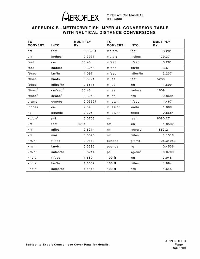
OPERATION MANUAL IFR 6000
APPENDIX B Subject to Export Control , see Cover Page for deta i ls . Page 1
Dec 1/09
APPENDIX B - METRIC/BRITISH IMPERIAL CONVERSION TABLE WITH NAUTICAL DISTANCE CONVERSIONS
TO CONVERT:
INTO:
MULTIPLY BY:
TO CONVERT:
INTO:
MULTIPLY BY:
cm feet 0 .03281 meters feet 3 .281
cm inches 0.3937 meters inches 39.37
feet cm 30.48 m/sec f t /sec 3.281
feet meters 0.3048 m/sec km/hr 3 .6
f t /sec km/hr 1 .097 m/sec mi les/hr 2 .237
f t /sec knots 0 .5921 mi les feet 5280
f t /sec mi les/hr 0 .6818 mi les km 1.609
f t /sec2 cm/sec2 30.48 mi les meters 1609
f t /sec2 m/sec2 0 .3048 mi les nmi 0 .8684
grams ounces 0.03527 mi les/hr f t /sec 1.467
inches cm 2.54 mi les/hr km/hr 1 .609
kg pounds 2.205 mi les/hr knots 0 .8684
kg/cm2 ps i 0 .0703 nmi feet 6080.27
km feet 3281 nmi km 1.8532
km mi les 0.6214 nmi meters 1853.2
km nmi 0 .5396 nmi mi les 1.1516
km/hr f t /sec 0.9113 ounces grams 28.34953
km/hr knots 0.5396 pounds kg 0.4536
km/hr mi les/hr 0 .6214 ps i kg/cm2 0.0703
knots f t /sec 1.689 100 f t km 3.048
knots km/hr 1 .8532 100 f t mi les 1.894
knots mi les/hr 1 .1516 100 f t nmi 1 .645

OPERATION MANUAL IFR 6000
APPENDIX B Subject to Export Control , see Cover Page for deta i ls . Page 2
Dec 1/09
THIS PAGE INTENTIONALLY LEFT BLANK.

OPERATION MANUAL IFR 6000
APPENDIX C Subject to Export Control , see Cover Page for deta i ls . Page 1
Dec 1/09
APPENDIX C - FACTORY/POWER UP PRESETS
Setup General
CONTROL FACTORY POWER UP
POWER DOWN 10 mins Last Used
ERP UNITS dBm Last Used
UNITS Feet Last Used
REMOTE OPERATION RS-232 Last Used
Setup XPDR Screen
FIELD FACTORY POWER UP
ANTENNA SELECTION Bot tom Last Used
RF PORT Antenna Last Used
ANTENNA RANGE 12 feet Last Used
ANTENNA HEIGHT 1 foot Last Used
DIR CABLE LOSS 1.2 dB Last Used
ANT CABLE User Def ined Last Used
ANT CABLE LOSS 0.1 dB Last Used
ANT GAIN 1.03 GHZ 7.1 dB Last Used
ANT GAIN 1.09 GHZ 6.1 dB Last Used
UUT ADDRESS AUTO AUTO
MANUAL AA 000000 Last Used
DIVERSITY TEST ON Last Used
CONFIG TYPE GENERIC MODE S Last Used

OPERATION MANUAL IFR 6000
APPENDIX C Subject to Export Control , see Cover Page for deta i ls . Page 2
Dec 1/09
Setup DME Screen
F IELD FACTORY POWER UP
RF PORT Antenna Last Used
ANTENNA RANGE 12 feet Last Used
IDENT TONE IFR Last Used
DIR CABLE LOSS 1.2 dB Last Used
CABLE LOSS 1.3dB Last Used
ANT CABLE User Def ined Last Used
ANT CABLE LOSS 0.1 dB Last Used
ANT GAIN 0.96 GHZ 7.5 dB Last Used
ANT GAIN 1.03 GHZ 7.1 dB Last Used
ANT GAIN 1.09 GHZ 6.1 dB Last Used
ANT GAIN 1.15 GHZ 5.0 dB Last Used
ANT GAIN 1.22 GHZ 2.8 dB Last Used
MAX RANGE 400 nm Last Used
DME Screen
FIELD FACTORY POWER UP
VOR / FREQ / CHAN 978/108.00/17X 978/108.00/17X
RF LVL Maximum Maximum
RANGE 0 nm 0 nm
RATE 10 k ts 10 k ts
RATE DIRECTION OUT OUT
% REPLY 100% 100%
ECHO OFF OFF
IDENT ON ON
SQTR ON ON
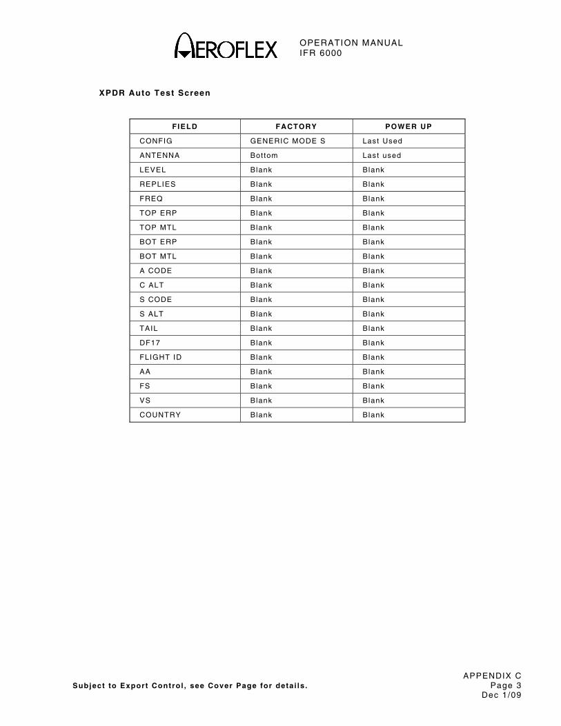
OPERATION MANUAL IFR 6000
APPENDIX C Subject to Export Control , see Cover Page for deta i ls . Page 3
Dec 1/09
XPDR Auto Test Screen
FIELD FACTORY POWER UP
CONFIG GENERIC MODE S Last Used
ANTENNA Bot tom Last used
LEVEL Blank Blank
REPLIES Blank Blank
FREQ Blank Blank
TOP ERP Blank Blank
TOP MTL Blank Blank
BOT ERP Blank Blank
BOT MTL Blank Blank
A CODE Blank Blank
C ALT Blank Blank
S CODE Blank Blank
S ALT Blank Blank
TAIL Blank Blank
DF17 Blank Blank
FLIGHT ID Blank Blank
AA Blank Blank
FS Blank Blank
VS Blank Blank
COUNTRY Blank Blank
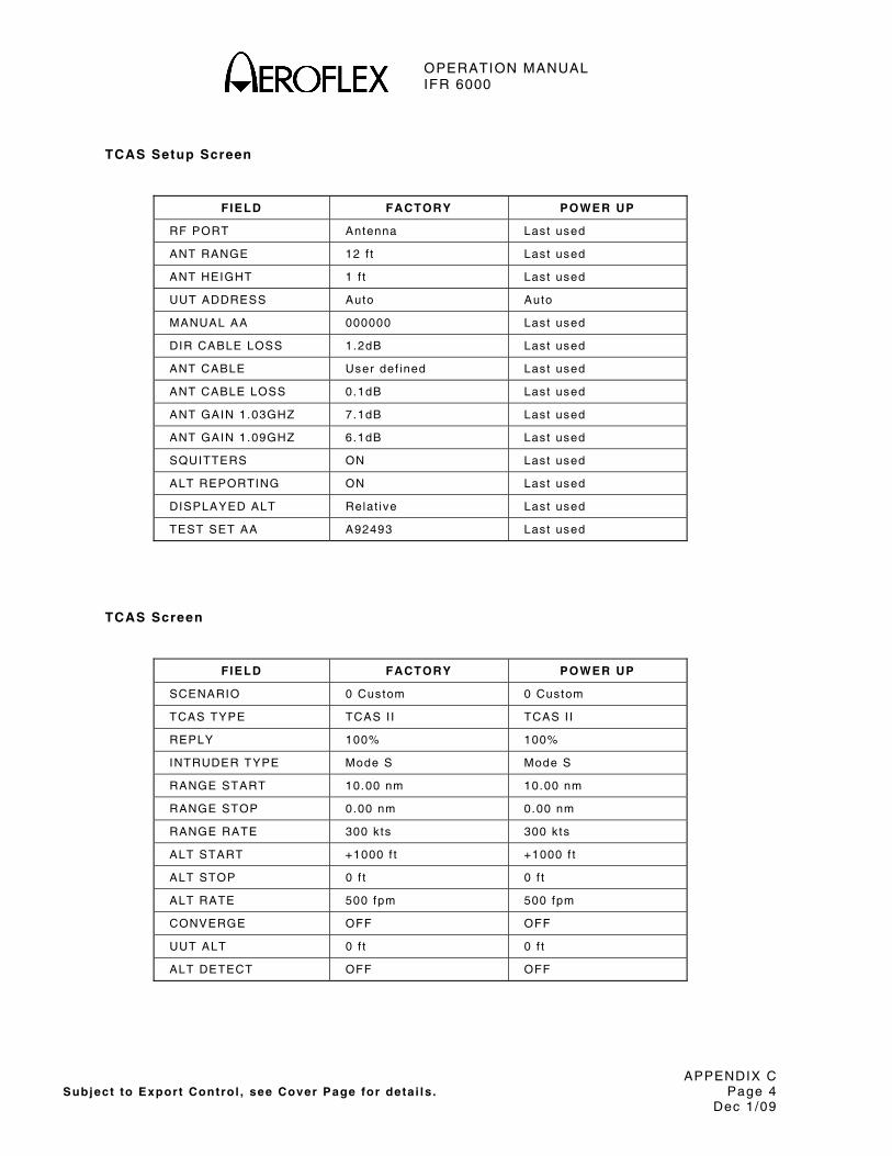
OPERATION MANUAL IFR 6000
APPENDIX C Subject to Export Control , see Cover Page for deta i ls . Page 4
Dec 1/09
TCAS Setup Screen
FIELD FACTORY POWER UP
RF PORT Antenna Last used
ANT RANGE 12 f t Last used
ANT HEIGHT 1 f t Last used
UUT ADDRESS Auto Auto
MANUAL AA 000000 Last used
DIR CABLE LOSS 1.2dB Last used
ANT CABLE User def ined Last used
ANT CABLE LOSS 0.1dB Last used
ANT GAIN 1.03GHZ 7.1dB Last used
ANT GAIN 1.09GHZ 6.1dB Last used
SQUITTERS ON Last used
ALT REPORTING ON Last used
DISPLAYED ALT Relat ive Last used
TEST SET AA A92493 Last used
TCAS Screen
FIELD FACTORY POWER UP
SCENARIO 0 Custom 0 Custom
TCAS TYPE TCAS I I TCAS I I
REPLY 100% 100%
INTRUDER TYPE Mode S Mode S
RANGE START 10.00 nm 10.00 nm
RANGE STOP 0.00 nm 0.00 nm
RANGE RATE 300 k ts 300 k ts
ALT START +1000 f t +1000 f t
ALT STOP 0 f t 0 f t
ALT RATE 500 fpm 500 fpm
CONVERGE OFF OFF
UUT ALT 0 f t 0 f t
ALT DETECT OFF OFF

OPERATION MANUAL IFR 6000
APPENDIX C Subject to Export Control , see Cover Page for deta i ls . Page 5
Dec 1/09
ADS-B Setup Screen
FIELD FACTORY POWER UP
POS DECODE Global Last used
LAT 90 0 O N Last used
LONG 180 0 0 E Last used
ADS-B GEN DF17 Last used
ADS-B MON DF17 Last used
GICB DF20 Last used
ADS-B GEN BDS 0,5 Screen
FIELD FACTORY POWER UP
TYPE 9 9
DF 18 Last used
AA A92492 A92492
PERIOD 1.00 s 1.00 s
LAT 0 0 0 N 0 0 0 N
LONG 0 0 0 E 0 0 0 E
POS - -
SAF 0 0
T N/UTC N/UTC
SURVEILLANCE STATUS
No info No info
BARO PRES ALT 0 f t 0 f t
GNSS ALT - -

OPERATION MANUAL IFR 6000
APPENDIX C Subject to Export Control , see Cover Page for deta i ls . Page 6
Dec 1/09
ADS-B GEN BDS 0,6 Screen
FIELD FACTORY POWER UP
TYPE 5 5
DF 17 Last used
AA A92492 A92492
PERIOD 1.00 s 1.00 s
LAT 0 0 0 N 0 0 0 N
LONG 0 0 0 E 0 0 0 E
MOVEMENT No info No info
T N/UTC N/UTC
HDG 0 deg 0 deg
ADS-B GEN BDS 0,8 Screen
FIELD FACTORY POWER UP
TYPE 1 1
DF 18 Last used
COUNT 0 Last used
AA A92492 A92492
PERIOD 1.00 s 1.00 s
FLIGHT ID ++++++++ ++++++++
EMIT CAT SET D D
EMIT CAT Reserved Reserved

OPERATION MANUAL IFR 6000
APPENDIX C Subject to Export Control , see Cover Page for deta i ls . Page 7
Dec 1/09
ADS-B GEN BDS 0,9 Screen
FIELD FACTORY POWER UP
TYPE 19 19
DF 17 Last used
AA A92492 A92492
PERIOD 1.00 s 1.00 s
E-W 0 k ts E 0 k ts E
NACV 0 0
N-S 0 k ts N 0 k ts N
HDG - -
SUBTYPE 1 – vel ovr gnd norm 1 – vel ovr gnd norm
VERT RATE 0 f t / min 0 f t / min
GEO ALT DIFF FROM BARO
0 f t 0 f t
SOURCE GEO GEO
INTENT CHANGE NO NO
AIRSPEED - -
AIRSPEED TYPE - -
IFR CAP ADS-B/CLASS A1>
NO NO
ADS-B GEN BDS 6,1 Screen
FIELD FACTORY POWER UP
TYPE 28 28
DF 18 Last used
AA A92492 A92492
PERIOD 1.00 s 1.00 s
EMERG / PRIOR CODE 0 – No info 0 – No info
RESERVED 000000000000 000000000000
SUBTYPE 0 – No info 0 – No info
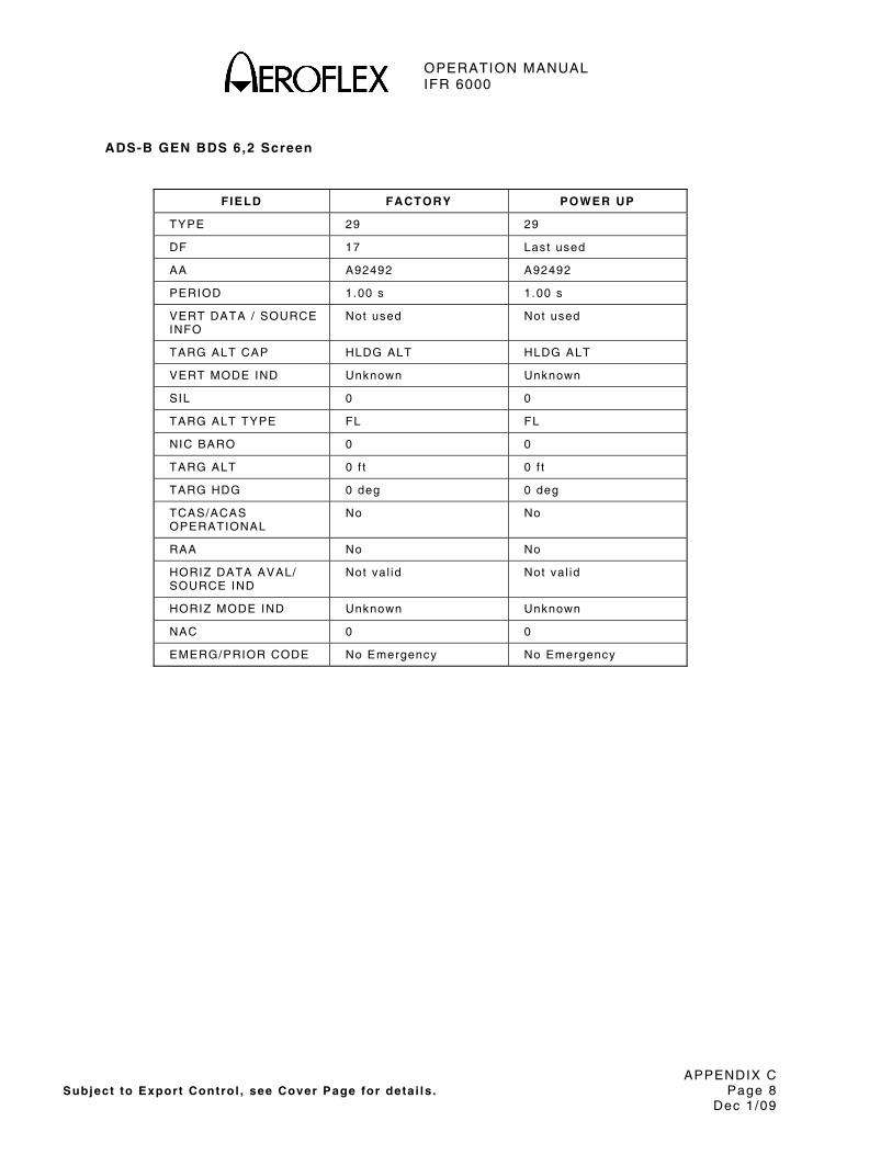
OPERATION MANUAL IFR 6000
APPENDIX C Subject to Export Control , see Cover Page for deta i ls . Page 8
Dec 1/09
ADS-B GEN BDS 6,2 Screen
FIELD FACTORY POWER UP
TYPE 29 29
DF 17 Last used
AA A92492 A92492
PERIOD 1.00 s 1.00 s
VERT DATA / SOURCE INFO
Not used Not used
TARG ALT CAP HLDG ALT HLDG ALT
VERT MODE IND Unknown Unknown
SIL 0 0
TARG ALT TYPE FL FL
NIC BARO 0 0
TARG ALT 0 f t 0 f t
TARG HDG 0 deg 0 deg
TCAS/ACAS OPERATIONAL
No No
RAA No No
HORIZ DATA AVAL/ SOURCE IND
Not val id Not val id
HORIZ MODE IND Unknown Unknown
NAC 0 0
EMERG/PRIOR CODE No Emergency No Emergency

OPERATION MANUAL IFR 6000
APPENDIX C Subject to Export Control , see Cover Page for deta i ls . Page 9
Dec 1/09
ADS-B GEN BDS 6,3 Screen
FIELD FACTORY POWER UP
TYPE 31 31
DF 18 Last used
AA A92492 A92492
PERIOD 1.00 s 1.00 s
SUBTYPE D-ai rborne D-ai rborne
NAC D D
BAQ D D
SIL 0 0
TC 0 0
CDTI 0 0
ARV 0 0
TS 0 0
RA 0 0
VER NBR Do-260 / Do-242 Do-260 / Do-242
NOT-TCAS 0 0
OPER MODE SUBFIELD 0 0
NIC BARO 0 0
HORIZ REF DIR True North True North
IDENT No No
TRK/HDG - -
NIC 0 0
LENGTH/WIDTH - -
REC ATC SERV 0 0
B2 LOW - -
POA - -

OPERATION MANUAL IFR 6000
APPENDIX C Subject to Export Control , see Cover Page for deta i ls . Page 10
Dec 1/09
Setup TIS Screen
FIELD FACTORY POWER UP
RF PORT Antenna Last used
ANT RANGE 12 f t Last used
ANT HEIGHT 1 f t Last used
DIR CABLE LOSS 1.2 dB Last used
ANT CABLE User def ined Last used
ANT CABLE LOSS 0.1 dB Last used
ANT GAIN 1.03 GHz 7.1 Last used
ANT GAIN 1.09 GHz 6.1 Last used
UUT ADDRESS Auto Auto
MANUAL AA 000000 Last used
TIS Screen
FIELD FACTORY POWER UP
TARGETS 5 Last used
UUT HDG 0 Last used
BRG (deg) (1-5) 0 Last used
RNG (nm) (1-5) 0 Last used
ALT ( f t ) (1-5) 0 Last used
ALT RATE Level Last used
HDG (1-5) 0 Last used
TRAFFIC (1-5) Prox Last used
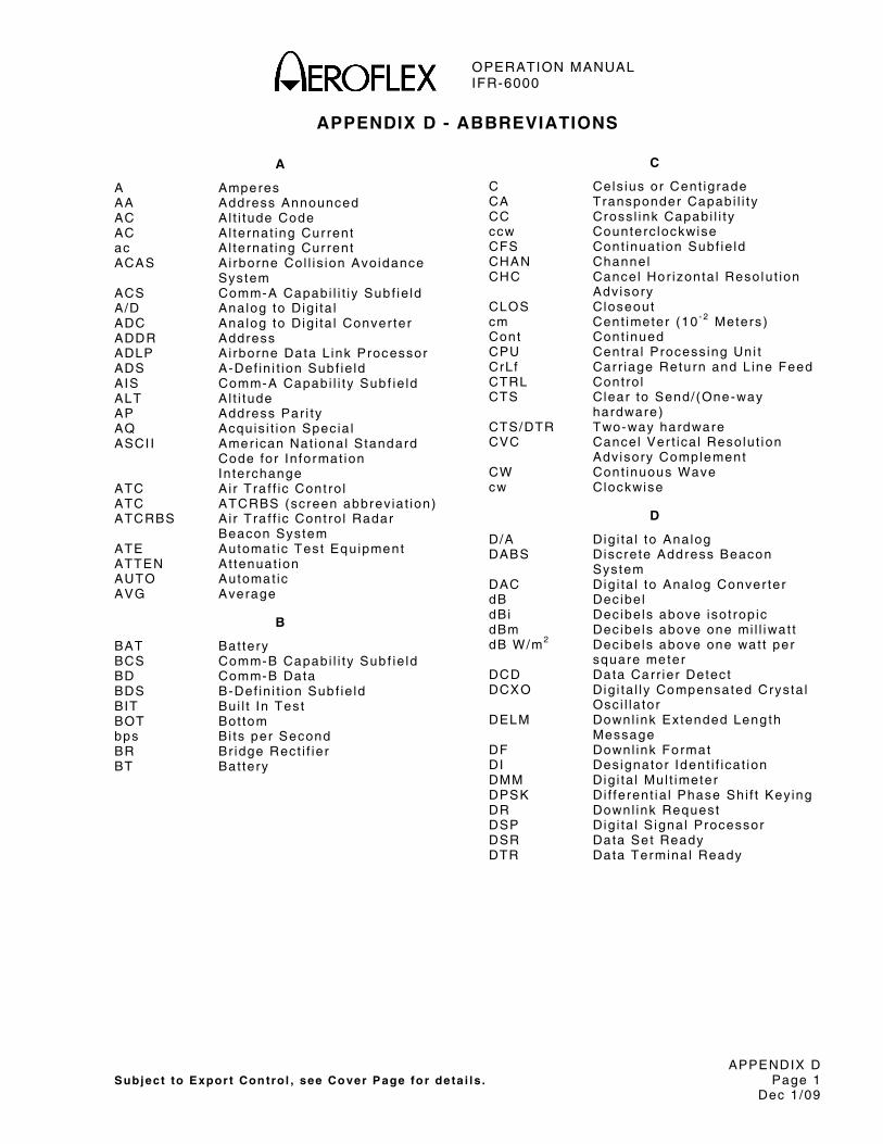
OPERATION MANUAL IFR-6000
APPENDIX D Subject to Expor t Control , see Cover Page fo r de ta i ls . Page 1
Dec 1/09
APPENDIX D - ABBREVIATIONS
A
A Amperes AA Address Announced AC Al t i tude Code AC Al ternat ing Cur rent ac Al ternat ing Cur rent ACAS Ai rborne Col l is ion Avoidance
System ACS Comm-A Capabi l i t iy Sub f ie ld A/D Analog to Dig i ta l ADC Analog to Dig i ta l Conver ter ADDR Address ADLP Ai rborne Data L ink Processor ADS A-Def in i t ion Subf ie ld AIS Comm-A Capabi l i ty Sub f ie ld ALT Al t i tude AP Address Par i ty AQ Acquis i t ion Specia l ASCI I Amer ican Nat ional Standard
Code for In format ion In terchange
ATC Air Tra f f ic Cont ro l ATC ATCRBS (screen abbrev iat ion) ATCRBS Ai r Tra f f ic Cont ro l Radar
Beacon System ATE Automat ic Test Equipment ATTEN At tenuat ion AUTO Automat ic AVG Average
B
BAT Bat tery BCS Comm-B Capabi l i ty Sub f ie ld BD Comm-B Data BDS B-Def in i t ion Subf ie ld BIT Bui l t In Test BOT Bot tom bps Bi ts per Second BR Br idge Rect i f ier BT Bat tery
C
C Cels ius or Cent igrade CA Transponder Capabi l i ty CC Cross l ink Capabi l i ty ccw Counterc lockwise CFS Cont inuat ion Subf ie ld CHAN Channel CHC Cancel Hor izonta l Resolut ion
Adv isory CLOS Closeout cm Cent imeter (10 - 2 Meters ) Cont Cont inued CPU Centra l Process ing Uni t CrLf Carr iage Retu rn and L ine Feed CTRL Contro l CTS Clear to Send/(One-way
hardware) CTS/DTR Two-way hardware CVC Cancel Ver t ica l Resolut ion
Advisory Complement CW Cont inuous Wave cw Clockwise
D
D/A Dig i ta l to Analog DABS Discrete Address Beacon
System DAC Dig i ta l to Analog Conver ter dB Decibe l dBi Decibe ls above isot rop ic dBm Decibe ls above one mi l l iwat t dB W/m2 Decibe ls above one wat t per
square meter DCD Data Carr ier Detect DCXO Dig i ta l ly Compensated Crysta l
Osc i l la tor DELM Downl ink Extended Leng th
Message DF Downl ink Format DI Designator Ident i f icat ion DMM Dig i ta l Mul t imeter DPSK Di f ferent ia l Phase Shi f t Key ing DR Downl ink Request DSP Dig i ta l S ignal Processor DSR Data Se t Ready DTR Data Terminal Ready
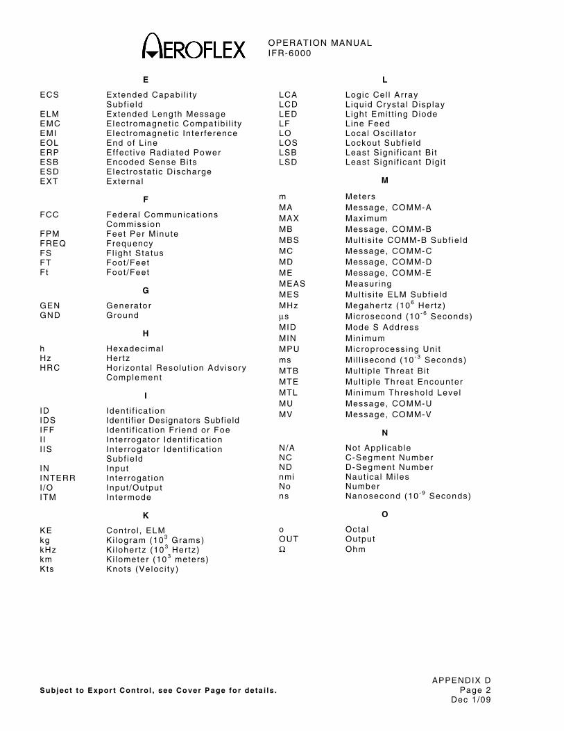
OPERATION MANUAL IFR-6000
APPENDIX D Subject to Expor t Control , see Cover Page fo r de ta i ls . Page 2
Dec 1/09
E
ECS Extended Capabi l i ty Subf ie ld ELM Extended Length Message EMC Elect romagnet ic Compat ib i l i ty EMI Elect romagnet ic In te r ference EOL End of L ine ERP Ef fect ive Radia ted Power ESB Encoded Sense Bi ts ESD Elect rostat ic Discharge EXT External
F
FCC Federa l Communicat ions Commiss ion
FPM Feet Per Minu te FREQ Frequency FS Fl ight Status FT Foot /Feet Ft Foot /Feet
G
GEN Generato r GND Ground
H
h Hexadecimal Hz Hertz HRC Hor izonta l Resolut ion Advisory
Complement
I
ID Ident i f icat ion IDS Identi f ier Designators Subfield IFF Ident i f icat ion Fr iend or Foe I I In ter rogato r Ident i f icat ion I IS In ter rogato r Ident i f icat ion
Subf ie ld IN Input INTERR Interrogat ion I /O Input /Output ITM Intermode
K
KE Contro l , ELM kg Ki logram (103 Grams) kHz Ki loher tz (10 3 Hertz) km Ki lometer (10 3 meters) Kts Knots (Veloc i ty )
L
LCA Logic Cel l Ar ray LCD L iqu id Crysta l Disp lay LED L ight Emi t t ing Diode LF L ine Feed LO Local Osc i l la tor LOS Lockout Subf ie ld LSB Least S ign i f icant B i t LSD Least S ign i f icant Dig i t
M
m Meters MA Message, COMM-A MAX Maximum MB Message, COMM-B MBS Mul t is i te COMM-B Subf ie ld MC Message, COMM-C MD Message, COMM-D ME Message, COMM-E MEAS Measur ing MES Mul t is i te ELM Subf ie ld MHz Megaher tz (106 Hertz) μs Microsecond (10 - 6 Seconds) MID Mode S Address MIN Min imum MPU Microprocess ing Uni t ms Mi l l isecond (10 - 3 Seconds) MTB Mul t ip le Threat B i t MTE Mul t ip le Threat Encounter MTL Min imum Threshold Level MU Message, COMM-U MV Message, COMM-V
N
N/A Not Appl icable NC C-Segment Number ND D-Segment Number nmi Naut ica l Mi les No Number ns Nanosecond (10 - 9 Seconds)
O
o Octa l OUT Output Ω Ohm
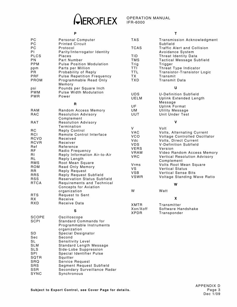
OPERATION MANUAL IFR-6000
APPENDIX D Subject to Expor t Control , see Cover Page fo r de ta i ls . Page 3
Dec 1/09
P
PC Personal Computer PC Pr in ted Ci rcu i t PC Protocol PI Par i ty / In te r rogato r Ident i ty PLCS Places PN Part Number PPM Pulse Posi t ion Modulat ion ppm Par ts per Mi l l ion PR Probabi l i ty o f Reply PRF Pulse Repet i t i on Frequency PROM Programmable Read Only
Memory ps i Pounds per Square Inch PWM Pulse Width Modulat ion PWR Power
R
RAM Random Access Memory RAC Resolut ion Adv isory
Complement RAT Resolut ion Advisory
Termina t ion RC Reply Cont ro l RCI Remote Contro l In ter face RCVD Received RCVR Receiver Ref Reference RF Radio Frequency RI Reply In format ion Ai r - to-Ai r RL Reply Length RMS Root Mean Square ROM Read Only Memory RR Reply Request RRS Reply Request Subf ie ld RSS Reservat ion Status Subf ie ld RTCA Requi rements and Technica l
Concepts for Av iat ion organizat ion
RTS Request to Sent RX Receive RXD Receive Data
S
SCOPE Osci l loscope SCPI Standard Commands for
Programmable Inst ruments organizat ion
SD Specia l Designato r Sec Second SL Sensi t iv i ty Level SLM Standard Leng th Message SLS Side-Lobe Suppress ion SPI Specia l Ident i f ie r Pulse SQTR Squi t ter SRQ Serv ice Request SRS Segment Request Subf ie ld SSR Secondary Survei l lance Radar SYNC Synchronous
T
TAS Transmiss ion Acknowledgment Subf ie ld
TCAS Traf f ic A le r t and Col l is ion Avoidance System
TID Threat Ident i ty Data TMS Tact ica l Message Subf ie ld Tr ig Tr igger TTI Threat Type Ind ica tor TTL Trans is tor -Trans is tor Logic TX Transmi t TXD Transmi t Data
U
UDS U-Def in i t ion Subf ie ld UELM Upl ink Extended Length
Message UF Upl ink Format UM Ut i l i ty Message UUT Uni t Under Test
V
V Vol t VAC Vol ts , A l te rnat ing Current VCO Vol tage Contro l led Osci l la tor Vdc Vol ts , Di rect Current VDS V-Def in i t ion Subf ie ld VERS Vers ion VRAM Video Random Access Memory VRC Ver t ica l Resolu t ion Adv isory
Complement Vrms Vol ts Root Mean Square VS Ver t ica l Status VSB Ver t ica l Sense Bi ts VSWR Vol tage Standing Wave Rat io
W
W Watt
X
XMTR Transmi t ter Xon/Xof f Sof tware Handshake XPDR Transponder
OPERATION MANUAL IFR-6000
APPENDIX D Subject to Expor t Control , see Cover Page fo r de ta i ls . Page 4
Dec 1/09
THIS PAGE INTENTIONALLY LEFT BLANK.
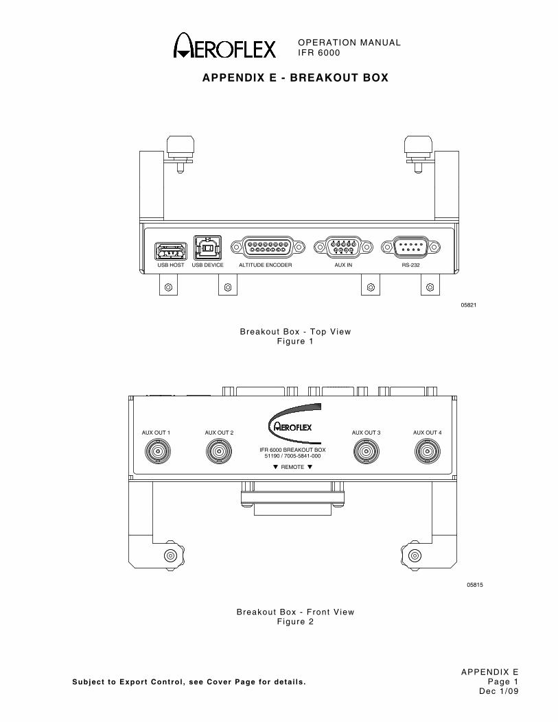
OPERATION MANUAL IFR 6000
APPENDIX E Subject to Export Control , see Cover Page for deta i ls . Page 1
Dec 1/09
APPENDIX E - BREAKOUT BOX
ALTITUDE ENCODERUSB HOST USB DEVICE AUX IN RS-232
05821
Breakout Box - Top View Figure 1
AUX OUT 1 AUX OUT 2
REMOTE
IFR 6000 BREAKOUT BOX51190 / 7005-5841-000
AUX OUT 3 AUX OUT 4
05815
Breakout Box - Front V iew Figure 2

OPERATION MANUAL IFR 6000
APPENDIX E Subject to Export Control , see Cover Page for deta i ls . Page 2
Dec 1/09
1. USB HOST CONNECTOR
05810
1 2 3 4
PIN NO. SIGNAL NAME SIGNAL TYPE DESCRIPTION
1 VBUS_DN1 Supply +5 V supply for USB device port
2 H_D- In/Out USB Host Data Compl iment
3 H_D+ In/Out USB Host Data True
4 GND_DN1 Ground Ground for USB device port
USB HOST Connector Table Table 1
2. USB DEVICE CONNECTOR
123 4
05811
PIN NO. SIGNAL NAME SIGNAL TYPE DESCRIPTION
1 VBUS_UP Supply +5 V supply input f rom USB host
2 D_D- In/Out USB Host Data Compl iment
3 D_D+ In/Out USB Host Data True
4 GND_UP Ground Ground for USB host port
USB DEVICE Connector Table Table 2
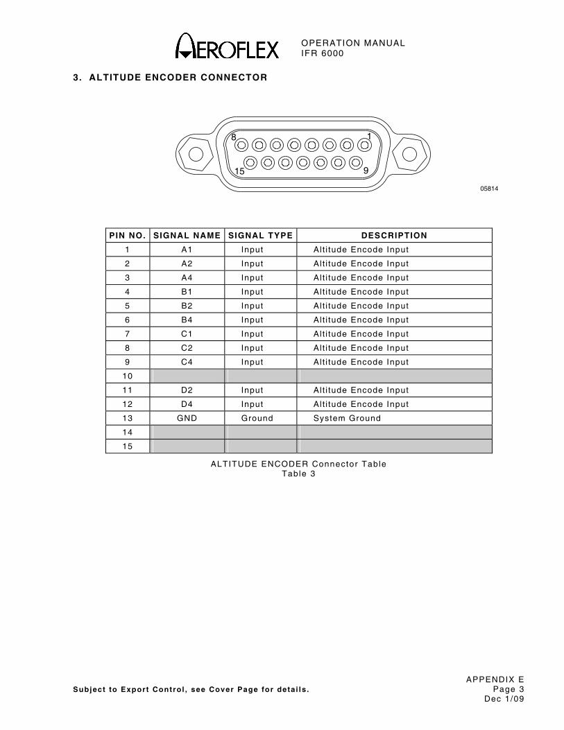
OPERATION MANUAL IFR 6000
APPENDIX E Subject to Export Control , see Cover Page for deta i ls . Page 3
Dec 1/09
3. ALTITUDE ENCODER CONNECTOR
18
915
05814
PIN NO. SIGNAL NAME SIGNAL TYPE DESCRIPTION
1 A1 Input Al t i tude Encode Input
2 A2 Input Al t i tude Encode Input
3 A4 Input Al t i tude Encode Input
4 B1 Input Al t i tude Encode Input
5 B2 Input Al t i tude Encode Input
6 B4 Input Al t i tude Encode Input
7 C1 Input Al t i tude Encode Input
8 C2 Input Al t i tude Encode Input
9 C4 Input Al t i tude Encode Input
10
11 D2 Input Al t i tude Encode Input
12 D4 Input Al t i tude Encode Input
13 GND Ground System Ground
14
15
ALTITUDE ENCODER Connector Table Table 3

OPERATION MANUAL IFR 6000
APPENDIX E Subject to Export Control , see Cover Page for deta i ls . Page 4
Dec 1/09
4. AUX IN CONNECTOR
12345
6789
05813
PIN NO. SIGNAL NAME SIGNAL TYPE DESCRIPTION
1 REM_IN1 Input General Purpose Input
2 REM_IN2 Input General Purpose Input
3 REM_IN3 Input General Purpose Input
4 REM_IN4 Input General Purpose Input
5 GND Ground System Ground
6 GND Ground System Ground
7 GND Ground System Ground
8 GND Ground System Ground
9 DNU Supply Do Not Use, Reserved
AUX IN Connector Table Table 4

OPERATION MANUAL IFR 6000
APPENDIX E Subject to Export Control , see Cover Page for deta i ls . Page 5
Dec 1/09
5. RS-232 CONNECTOR
1 5
6 9
05812
PIN NO. SIGNAL NAME SIGNAL TYPE DESCRIPTION
1
2 HOST_TXD BIPOLAR RS-232 Data Output
3 HOST_RXD BIPOLAR RS-232 Data Input
4
5 GND Ground System Ground
6
7 HOST_CTS BIPOLAR RS-232 Clear to Send (Input)
8 HOST_RTS BIPOLAR RS-232 Clear to Send (Output)
9
RS-232 Connector Table Table 5

OPERATION MANUAL IFR 6000
APPENDIX E Subject to Export Control , see Cover Page for deta i ls . Page 6
Dec 1/09
6. AUX OUT CONNECTORS
51190 / 7005-5841-000IFR 6000 BREAKOUT BOX
REMOTE
AUX OUT 1 AUX OUT 2 AUX OUT 4AUX OUT 3
05816
CONNECTOR SIGNAL TYPE DESCRIPTION
AUX OUT 1 Output Mode S Interrogat ion Tr igger
AUX OUT 2 Output ATCRBS Interrogat ion Trigger
AUX OUT 3 Output Not Used
AUX OUT 4 Output Not Used
Remote OUT Connector Table Table 6

OPERATION MANUAL IFR 6000
APPENDIX E Subject to Export Control , see Cover Page for deta i ls . Page 7
Dec 1/09
7. REMOTE CONNECTOR
05807
15 1
314430 16
PIN NO. SIGNAL NAME SIGNAL TYPE DESCRIPTION
1 VBUS_DN1 Supply +5 V supply for USB device port
2 GND_DN1 Ground Ground for USB device port
3 VBUS_UP Supply +5 V supply input f rom USB host
4 GND_UP Ground Ground for USB host port
5 GND Ground System Ground
6 HOST-RTS Output RS-232 Request to send
7 A2 Input Al t i tude Encode Input
8 A4 Input Al t i tude Encode Input
9 C2 Input Al t i tude Encode Input
10 C4 Input Al t i tude Encode Input
11 GND Ground System Ground
12 REM_IN1 Input General Purpose Input
13 REM_OUT2 Output General Purpose Output
14 GND Ground System Ground
15 GND Ground System Ground
16 H_D- In/Out USB Host Data Compl iment
17 H_D+ In/Out USB Host Data True
18 D_D- In/Out USB Host Data Compl iment
19 D_D+ In/Out USB Host Data True
20 GND Ground System Ground
21 HOST_TXD Output RS-232 Data Output
22 HOST_CTS Input RS-232 Clear to send
23 B1 Input Al t i tude Encode Input
24 B2 Input Al t i tude Encode Input
25 D2 Input Al t i tude Encode Input
REMOTE Connector P in-Out Table Table 2

OPERATION MANUAL IFR 6000
APPENDIX E Subject to Export Control , see Cover Page for deta i ls . Page 8
Dec 1/09
7. REMOTE CONNECTOR (cont)
PIN NO. SIGNAL NAME SIGNAL TYPE DESCRIPTION
26 GND Ground System Ground
27 REM_IN2 Input General Purpose Input
28 REM_IN3 Input General Purpose Input
29 REM_OUT4 Output General Purpose Output
30 GND Ground System Ground
31 VBUS_DN1 Supply +5 V supply for USB device port
32 VBUS_DN1 Supply +5 V supply for USB device port
33 VBUS_UP Supply +5 V supply input f rom USB host
34 GND_UP Ground Ground for USB host port
35 GND Ground System Ground
36 HOST_RXD Input RS-232 Data Input
37 A1 Input Al t i tude Encode Input
38 B4 Input Al t i tude Encode Input
39 C1 Input Al t i tude Encode Input
40 REM_SP1 Spare Pin
41 D4 Input Al t i tude Encode Input
42 REM_IN4 Input General Purpose Input
43 REM_OUT1 Output General Purpose Output
44 REM_OUT3 Output General Purpose Output
REMOTE Connector P in-Out Table (cont) Table 2

OPERATION MANUAL IFR 6000
APPENDIX F Subject to Export Control , see Cover Page for deta i ls . Page 1
Dec 1/09
APPENDIX F - CONFIGURATIONS
Configurat ion TX Power (dBm) RX MTL (dBm) TX Freq (MHz)
GENERIC ATCRBS 48.5 to 57.0 -73 (±4) 1090 (±3)
ATCRBS CLASS A 51.0 to 57.0 -73 (±4) 1090 (±3)
ATCRBS CLASS B 48.5 to 57.0 -73 (±4) 1090 (±3)
GENERIC MODE S 48.5 to 57.0 -74 (±3) 1090 (±3)
MODE S CLASS A 51.0 to 57.0 -74 (±3) 1090 (±1)
MODE S CLASS B 48.5 to 57.0 -74 (±3) 1090 (±3)
MODE S CL B OPT FRQ 48.5 to 57.0 -74 (±3) 1090 (±1)
MODE S CL B OPT POW 51.0 to 57.0 -74 (±3) 1090 (±3)

OPERATION MANUAL IFR 6000
APPENDIX F Subject to Export Control , see Cover Page for deta i ls . Page 2
Dec 1/09
THIS PAGE INTENTIONALLY LEFT BLANK.

OPERATION MANUAL IFR 6000
APPENDIX G Subject to Expor t Control , see Cover Page fo r de ta i ls . Page 1
Dec 1/09
APPENDIX G - MODE S ADDRESS BLOCKS This tab le conta ins Mode S address b locks for countr ies whose ta i l numbers are decoded by the IFR 6000. For an expanded l is t o f Mode S codes, re fer to Appendix H.
COUNTRY ADDRESS BLOCK
Belg ium 448000 - 448FFF
Canada C00000 - C3FFFF
Denmark 458000 - 45FFFF
France 380000 - 3AFFFF
Germany 3C0000 - 3FFFFF
Poland 488000 - 48FFFF
Swi tzer land 4B0000 - 4B7FFF
USA A00000 - AFFFFF

OPERATION MANUAL IFR 6000
APPENDIX G Subject to Expor t Control , see Cover Page fo r de ta i ls . Page 2
Dec 1/09
THIS PAGE INTENTIONALLY LEFT BLANK.

OPERATION MANUAL IFR 6000
APPENDIX H Subject to Expor t Control , see Cover Page fo r de ta i ls . Page 1
Dec 1/09
APPENDIX H - MODE S ADDRESS BLOCKS This tab le conta ins a complete l is t o f Mode S address b locks. For count r ies whose ta i l numbers are decoded by the IFR 6000, re fer to Appendix G.
COUNTRY ADDRESS BLOCK COUNTRY ADDRESS BLOCK
Afghan is tan 70000 - 700FFF Braz i l E40000 - E4FFFF
A lban ia 501000 - 5013FF Brune i Darassa lam 895000 - 8953FF
A lger i a 0A0000 - 0A7FFF Bulga r ia 450000 - 457FFF
Angola 090000 - 090FFF Burk in Faso 09C000 - 09CFFF
Ant igua and Barbuda 0CA000 - 0CA3FF Burund i 032000 - 032FFF
Argent ina E00000 - E3FFFF Cambodia 70E000 - 70EFFF
Armenia 600000 - 6003FF Cameroon 034000 - 034FFF
Aus t ra l ia 7C0000 - 7FFFFF Canada C00000 - C3FFFF
Aus t r ia 440000 - 447FFF Cape Verde 096000 - 096FF
Azerba i jan 600800 - 600BFF Cent ra l A f r i c an Republ i c
06C000 - 06CFFF
Bahamas 0A8000 - 0A8FFF Chad 084000 - 084FFF
Bahra in 894000 - 894FFF Chi l e E80000 - E80FFF
Banglades h 702000 - 702FFF China 780000 - 78BFFF
Barbados 0AA000 - 0AA3FF Colombia 0AC000 - 0ACFFF
Belarus 510000 - 5103FF Comoros 035000 - 0353FF
Belg ium 448000 - 448FFF Congo 036000 - 036FFF
Bel i ze 0AB000 - 0AB3FF Cook Is lands 901000 - 9013FF
Benin 094000 - 0943FF Cos ta R ica 0AE000 - 0AEFFF
Bhutan 680000 - 6803FF Côte d / I vo i re 038000 - 038FFF
Bol iv ia E94000 - E94FFF Croat ia 501C00 - 501FFF
Bosn ia and Herz egov ina
513000 - 5133FF Cuba 0B0000 - 0B0FFF
Botswana 030000 - 0303FF
Cyprus 4C8000 - 4C83FF

OPERATION MANUAL IFR 6000
APPENDIX H Subject to Expor t Control , see Cover Page fo r de ta i ls . Page 2
Dec 1/09
COUNTRY ADDRESS BLOCK COUNTRY ADDRESS BLOCK
Czech Rep 498000 - 49FFFF Guinea-B issau 048000 - 0483FF
Dem Repub l ic Korea 72000 - 727FFF Guyana 0B6000 - 0B6FFF
Dem Republ ic Congo 08C000 - 08CFFF Hai t i 0B800 - 0B8FFF
Denmark 458000 - 45FFFF Honduras 0BA000 - 0BAFFF
Dj ibout i 098000 - 0983FF Hungary 470000 - 477FFF
Domin ic an Rep 0C4000 - 0C4FFF Ice land 4CC000 - 4CCFFF
Ecuador E84000 - E84FFF Ind ia 800000 - 83FFFF
Egypt 010000 - 017FFF Indones ia 8A0000 - 8A7FFF
E l Sa lvador 0B2000 - 0B2FFF I ran, I s lamic Rep 730000 - 737FFF
Equato r ia l Gu inea 042000 - 042FFF I raq 728000 - 72FFFF
Er i t rea 202000 - 2023FF I re land 4CA000 - 4CAFFF
Es ton ia 511000 - 5113FF Is rae l 738000 - 73FFFF
Eth iop ia 040000 - 040FFF I ta ly 300000 - 33FFFF
F i j i C88000 - C88FFF Jamaica 0BE000 - 0BEFFF
F in land 460000 - 467FFF Japan 840000 - 87FFFF
Franc e 380000 - 3AFFFF Jordan 740000 - 747FFF
Gabon 03E000 - 03EFFF Kazakhs tan 683000 - 6733FF
Gambia 09A000 - 09AFFF Kenya 04C000 - 04CFFF
Georg ia 514000 - 5143FF K i r iba t i C8E000 - C8E3FF
Germany 3C0000 - 3FFFFF Kuwai t 706000 - 706FFF
Ghana 044000 - 044FFF Kyrgyzs tan 601000 - 6013FF
Greece 468000 - 46FFFF Lao Dem Rep 708000 - 708FFF
Grenada 0C000 - 0CC3FF Latv ia 502C0 - 502FFF
Guatemala 0B4000 - 0B4FFF Lebanon 748000 - 74FFFF
Guinea 046000 - 046FFF
Lesotho 04A000 - 04A3FF

OPERATION MANUAL IFR 6000
APPENDIX H Subject to Expor t Control , see Cover Page fo r de ta i ls . Page 3
Dec 1/09
COUNTRY ADDRESS BLOCK COUNTRY ADDRESS BLOCK
Libe r ia 050000 - 050FFF New Zea land C80000 - C87FFF
L ibyan A rab Jam 018000 - 01FFFF Nicaragua 0C0000 - 0C0FFF
L i thuan ia 503C00 - 503FFF Nige r 062000 - 062FFF
Luxembourg 4D0000 - 4D03FF Nige r i a 064000 - 064FFF
Madagascar 054000 - 054FFF Norway 478000 - 47FFFF
Malawi 057000 - 058FFF Oman 70C000 - 70C3FF
Malays ia 75000 - 757FFF Pak is tan 760000 - 767FFF
Mald ives 05A000 - 05A3FF Palau 684000 - 6843FF
Mal i 05C000 - 05CFFF Panama 0C2000 - 0C2FFF
Mal ta 4D2000 - 4D23FF Papua New Guinea 898000 - 898FFF
Marsha l l I s lands 900000 - 9003FF Paraguay E88000 - E88FFF
Maur i t an ia 05E000 - 05D3FF Peru E8C000 - E8CFFF
Maur i t i us 060000 - 0603FF Phi l ipp ines 758000 - 75FFFF
Mex ico 0D0000 - 0D7FFF Poland 488000 - 48FFFF
Mic rones ia , Federa l S ta tes
681000 - 6813FF Por tuga l 490000 - 497FFF
Monaco 4D4000 - 4D43FF Qatar 06A000 - 06A3FF
Mongol ia 682000 - 6823FF Rep o f Korea 718000 - 71FFFF
Morocco 020000 - 027FFF Rep o f Moldova 504C00 - 504FFF
Mozambique 006000 - 006FFF Romania 4A0000 - 4A7FFF
Myanmar 704000 - 704FFF Russ ian Fed 100000 - 1FFFFF
Namib ia 201000 - 2013FF Rwanda 06E000 - 06EFFF
Nauru C8A000 - C8A3FF Sain t Luc ia C8C000 - C8C3FF
Nepal 70A000 - 70AFFF St V incent and Grenad ines
0BC000 - 0BC3FF
Nether l ands , K ingdom 480000 - 487FFF
Samoa 902000 - 9023FF

OPERATION MANUAL IFR 6000
APPENDIX H Subject to Expor t Control , see Cover Page fo r de ta i ls . Page 4
Dec 1/09
COUNTRY ADDRESS BLOCK COUNTRY ADDRESS BLOCK
San Mar i no 500000 - 5003FF The Fo rmer Yugos lav Republ i c o f Macedonia
512000 - 5123FF
Sao Tome and Pr inc ipe
09E000 - 09E3FF Togo 08800 - 088FFF
Saudi Arab ia 710000 - 717FFF Tonga C8D000 - C8D3FF
Senega l 070000 - 070FFF Tr in i dad and Tobago 0C6000 - 0C6FFF
Seyche l les 074000 - 0743FF Tun is ia 028000 - 02FFFF
S ier ra Leone 076000 - 0763FF Turkey 4B8000 - 4BFFFF
S ingapore 768000 - 76FFFF Turkmen is tan 601800 - 601BFF
S lovak ia 505C00 - 505FFF Uganda 068000 - 068FFF
S loven ia 506C00 - 506FFF Ukra ine 508000 - 50FFFF
Solomon Is lands 897000 - 8973FF Uni ted Arab Emira t es 896000 - 896FFF
Somal ia 078000 - 078FFF Uni ted K ingdom 400000 - 423FFFF
South A f r ica 008000 - 00FFFF Uni ted Rep o f Tanzan ia
080000 - 080FFF
Spa in 340000 - 37FFFF Uni ted S ta tes A00000 - AFFFFF
Sr i Lanka 770000 - 777FFF Uruguay E90000 - E00FFF
Sudan 07C000 - 07CFFF Uzbek is tan 507C00 - 507FFF
Sur iname 0C80000 - 0C8FFF Vanuat u C90000 - C903FF
Swaz i land 07A000 - 07A3FF Venezuela 0D8000 - 0DFFFF
Sweden 4A8000 - 4AFFFF V ie t Nam 888000 - 88FFFF
Swi tzer land 4B0000 - 4B7FFF Yemen 890000 - 890FFF
Syr ian Arab Rep 778000 - 77FFFF Zambia 08A000 - 08AFFF
Ta j i k is tan 515000 - 5153FF Z imbabwe 004000 - 0043FF
Tha i l and 880000 - 887FFF

OPERATION MANUAL IFR 6000
APPENDIX H Subject to Expor t Control , see Cover Page fo r de ta i ls . Page 5
Dec 1/09
COUNTRY ADDRESS BLOCK
Non-Cont rac t ing States
Yugos lav ia 4C0000 - 4C7FFF
Other Al locat ions
ICAO (1 ) F00000 - F07FFF
ICAO (2 ) 899000 - 8993FF
ICAO (2 ) F09000 - F093FF
(1) ICAO or i ts des ignate admin is ters th is b lock for ass ign ing temporary a i rcraf t addresses i f and when an immediate act ion is to be taken to avoid the ass ignment o f an unauthor ized 24-b i t a i rcra f t address. I t is in tended tha t the temporary address is to be re l inquished as soon as pract icable when the 24-b i t a i rcraf t address is ass igned by a Stat o f Regis t ry o r common mark reg is ter ing author i ty in confo rmance wi th the prov is ions in 4, 5 and 6 of the ICAO Annex 10 Vol . I I I . The State concerned is then expected to in fo rm ICAO or i ts des ignate regard ing the re lease of the temporary address.
(2) Block a l located for spec ia l use in the in te rest o f f l ight safety

OPERATION MANUAL IFR 6000
APPENDIX H Subject to Expor t Control , see Cover Page fo r de ta i ls . Page 6
Dec 1/09
THIS PAGE INTENTIONALLY LEFT BLANK.

OPERATION MANUAL IFR 6000
APPENDIX I Subject to Export Control , see Cover Page for deta i ls . Page 1
Dec 1/09
APPENDIX I - SIGNAL FORMATS
1. OPERATING GOALS
Mode S combines secondary surve i l lance radar and a ground-a i r -ground data l ink system to prov ide a i rcraf t surve i l lance and communicat ions necessary for suppor t ing automated ATC in dense t ra f f ic env i ronments. Mode S prov ides common-channel in teroperat ion wi th the ATC beacon system and may be implemented over an extended ATCRBS-to-Mode S t rans i t ion per iod. In suppor t ing ATC automat ion, Mode S prov ides the re l iab le communicat ions necessary for data l ink serv ices.
2. MODE S MESSAGE CONTENT
2.1 ADDRESS/PARITY (FIELD AP)
Al l d iscrete Mode S in ter rogat ions (56-b i t or 112-b i t ) and rep l ies (except the Al l Cal l rep ly) conta in the 24-b i t d iscrete address of the Mode S t ransponder upon which 24 error -detect ing par i ty check b i ts are over la id . In the Al l Cal l rep ly , the 24 par i ty check b i ts are over la id on the address of the Mode S in ter rogator . The text o f the rep ly inc ludes the d iscrete address of the t ransponder .
2.2 SURVEILLANCE
The pr imary funct ion of Mode S is surve i l lance. For the Mode S t ransponder , th is funct ion is accompl ished by us ing shor t (56-b i t ) t ransmiss ions in both d i rect ions. In these t ransmiss ions, the a i rcraf t repor ts a l t i tude (DF04) or ATCRBS 4096 code as wel l as f l ight s ta tus (a i rborne, on the ground, a ler t , Specia l Posi t ion Ident i f icat ion [SPI ] , e tc . ) .
2.3 DATA LINK COMMUNICATIONS
The d iscrete address ing and d ig i ta l encoding a l low Mode S t ransmiss ions to be used as d ig i ta l data l inks. In ter rogat ion and rep ly formats of the Mode S system conta in suf f ic ient coding space to t ransmi t data. Most Mode S data l ink t ransmiss ions are handled as one 56-b i t message inc luded as par t o f long 112-b i t in ter rogat ions or rep l ies. The t ransmiss ions inc lude the message in addi t ion to surve i l lance data, and is genera l ly used in p lace of a surve i l lance in ter rogat ion and/or rep ly .
An ef f ic ient t ransmiss ion of longer messages is accompl ished by the extended length message (ELM) capabi l i ty (UF24 and DF24) . Us ing th is capabi l i ty , a sequence of up to s ix teen 80-b i t message segments (each wi th a 112-b i t t ransmiss ion) is t ransmi t ted, e i ther ground- to-a i r or a i r - to-ground and is acknowledged wi th a s ing le rep ly / in ter rogat ion. ELMs do not conta in surve i l lance data and thus cannot subst i tu te for a surve i l lance in ter rogat ion-rep ly cyc le .
3. SIGNAL FORMATS
Signal formats for up l ink and downl ink messages are out l ined in Chapter 2 , RTCA DO-181 and Chapter 2 , Volume I o f RTCA DO-185. Tables 1, 2 , 3 , 4 and 5 in Appendix B conta in the s ignal formats and def in i t ions. Data is expressed in dec imal un less otherwise speci f ied. Refer to Appendix B, Table 6 for convers ion to hexadecimal , octa l or b inary . Appendix B, Table 7 shows the ATC-601-2 f ixed formats for Mode S us ing Front Panel operat ion.
NOTE: TCAS operates in Mode S and many s ignals per ta in on ly to TCAS.

OPERATION MANUAL IFR 6000
APPENDIX I Subject to Export Control , see Cover Page for deta i ls . Page 2
Dec 1/09
FORMAT NO. UF
0 (0 0000) ⎯ 3 ⎯ (RL:1)⎯ 4 ⎯ (AQ:1) (BD:8)⎯ 10 ⎯ (AP:24) . . . . . . . . Shor t A i r -A i r Survei l lance
1 (0 0001) ⎯⎯⎯⎯⎯⎯⎯⎯ 27 or 83 ⎯⎯⎯⎯⎯⎯⎯⎯ (AP:24)
2 (0 0010) ⎯⎯⎯⎯⎯⎯⎯⎯ 27 or 83 ⎯⎯⎯⎯⎯⎯⎯⎯ (AP:24)
3 (0 0011) ⎯⎯⎯⎯⎯⎯⎯⎯ 27 or 83 ⎯⎯⎯⎯⎯⎯⎯⎯ (AP:24)
4 (0 0100) (PC:3) (RR:5) (DI :3) (SD:16) (AP:24) . Survei l lance, A l t i tude Request
5 (0 0101) (PC:3) (RR:5) (DI :3) (SD:16) (AP-24) . Survei l lance, Ident i ty Request
6 (0 0110) ⎯⎯⎯⎯⎯⎯⎯⎯ 27 or 83 ⎯⎯⎯⎯⎯⎯⎯⎯ (AP:24)
7 (0 0111) ⎯⎯⎯⎯⎯⎯⎯⎯ 27 or 83 ⎯⎯⎯⎯⎯⎯⎯⎯ (AP:24)
8 (0 1000) ⎯⎯⎯⎯⎯⎯⎯⎯ 27 or 83 ⎯⎯⎯⎯⎯⎯⎯⎯ (AP:24)
9 (0 1001) ⎯⎯⎯⎯⎯⎯⎯⎯ 27 or 83 ⎯⎯⎯⎯⎯⎯⎯⎯ (AP:24)
10 (0 1010) ⎯⎯⎯⎯⎯⎯⎯⎯ 27 or 83 ⎯⎯⎯⎯⎯⎯⎯⎯ (AP:24)
11 (0 1011) (PR:4) ( I I :4)⎯⎯⎯⎯⎯⎯ 19 ⎯⎯⎯⎯⎯⎯ (AP:24) . . . . . . . . . . . . . . . Mode S Only Al l Cal l
12 (0 1100) ⎯⎯⎯⎯⎯⎯⎯⎯ 27 or 83 ⎯⎯⎯⎯⎯⎯⎯⎯ (AP:24)
13 (0 1101) ⎯⎯⎯⎯⎯⎯⎯⎯ 27 or 83 ⎯⎯⎯⎯⎯⎯⎯⎯ (AP:24)
14 (0 1110) ⎯⎯⎯⎯⎯⎯⎯⎯ 27 or 83 ⎯⎯⎯⎯⎯⎯⎯⎯ (AP:24)
15 (0 1111) ⎯⎯⎯⎯⎯⎯⎯⎯ 27 or 83 ⎯⎯⎯⎯⎯⎯⎯⎯ (AP:24)
16 (1 0000) ⎯ 3 ⎯ (RL:1)⎯ 4 ⎯ (AQ:1)⎯ 18 ⎯ (MU:56) (AP:24) . . . . . . . . . Long Ai r -A i r Survei l lance
17 (1 0001) ⎯⎯⎯⎯⎯⎯⎯⎯ 27 or 83 ⎯⎯⎯⎯⎯⎯⎯⎯ (AP:24)
18 (1 0010) ⎯⎯⎯⎯⎯⎯⎯⎯ 27 or 83 ⎯⎯⎯⎯⎯⎯⎯⎯ (AP:24)
19 (1 0011) ⎯⎯⎯⎯⎯⎯⎯⎯ 27 or 83 ⎯⎯⎯⎯⎯⎯⎯⎯ (AP:24)
20 (1 0100) (PC:3) (RR:5) (DI :3) (SD:16) (MA:56) (AP:24) . . . . . . . Comm-A, Al t i tude Request
21 (1 0101) (PC:3) (RR:5) (DI :3) (SD:16) (MA:56) (AP:24) . . . . . . . Comm-A, Ident i ty Request
22 (1 0110) ⎯⎯⎯⎯⎯⎯⎯⎯ 27 or 83 ⎯⎯⎯⎯⎯⎯⎯⎯ (AP:24)
23 (1 0111) ⎯⎯⎯⎯⎯⎯⎯⎯ 27 or 83 ⎯⎯⎯⎯⎯⎯⎯⎯ (AP:24)
24 (1 1xxx) (RC:2) (NC:4) (MC:80) (AP:24) . . . . . . . . . . . . . . . . . . . . . . . Comm-C (ELM)
NOTE: (XX:M) represents a f ie ld des ignated XX conta in ing M number of ass igned b i ts .
NOTE: ⎯N⎯ represents f ree coding space wi th N avai lab le b i ts , coded as Zeros for t ransmiss ion.
NOTE: For Upl ink Formats (UF) 0 through 23, the format number corresponds to the b inary code in the f i rs t 5 b i ts o f the in ter rogat ion. Format number 24 is arb i t rar i ly def ined as the format beginning wi th Ones in the f i rs t two b i t pos i t ions. The fo l lowing three b i ts (xxx) vary wi th the in ter rogat ion content .
NOTE: A l l formats are shown for completeness, a l though a number of them are unused.
Overv iew of Mode S In ter rogat ion Formats Table 1
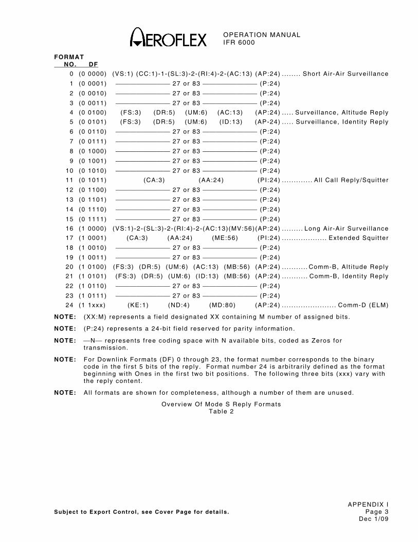
OPERATION MANUAL IFR 6000
APPENDIX I Subject to Export Control , see Cover Page for deta i ls . Page 3
Dec 1/09
FORMAT NO. DF
0 (0 0000) (VS:1) (CC:1)-1-(SL:3)-2-(RI :4)-2-(AC:13) (AP:24) . . . . . . . . Shor t A i r -A i r Survei l lance
1 (0 0001) ⎯⎯⎯⎯⎯⎯⎯⎯ 27 or 83 ⎯⎯⎯⎯⎯⎯⎯⎯ (P:24)
2 (0 0010) ⎯⎯⎯⎯⎯⎯⎯⎯ 27 or 83 ⎯⎯⎯⎯⎯⎯⎯⎯ (P:24)
3 (0 0011) ⎯⎯⎯⎯⎯⎯⎯⎯ 27 or 83 ⎯⎯⎯⎯⎯⎯⎯⎯ (P:24)
4 (0 0100) (FS:3) (DR:5) (UM:6) (AC:13) (AP:24) . . . . . Survei l lance, A l t i tude Reply
5 (0 0101) (FS:3) (DR:5) (UM:6) ( ID:13) (AP-24) . . . . . Surve i l lance, Ident i ty Reply
6 (0 0110) ⎯⎯⎯⎯⎯⎯⎯⎯ 27 or 83 ⎯⎯⎯⎯⎯⎯⎯⎯ (P:24)
7 (0 0111) ⎯⎯⎯⎯⎯⎯⎯⎯ 27 or 83 ⎯⎯⎯⎯⎯⎯⎯⎯ (P:24)
8 (0 1000) ⎯⎯⎯⎯⎯⎯⎯⎯ 27 or 83 ⎯⎯⎯⎯⎯⎯⎯⎯ (P:24)
9 (0 1001) ⎯⎯⎯⎯⎯⎯⎯⎯ 27 or 83 ⎯⎯⎯⎯⎯⎯⎯⎯ (P:24)
10 (0 1010) ⎯⎯⎯⎯⎯⎯⎯⎯ 27 or 83 ⎯⎯⎯⎯⎯⎯⎯⎯ (P:24)
11 (0 1011) (CA:3) (AA:24) (PI :24) . . . . . . . . . . . . . A l l Cal l Reply /Squi t ter
12 (0 1100) ⎯⎯⎯⎯⎯⎯⎯⎯ 27 or 83 ⎯⎯⎯⎯⎯⎯⎯⎯ (P:24)
13 (0 1101) ⎯⎯⎯⎯⎯⎯⎯⎯ 27 or 83 ⎯⎯⎯⎯⎯⎯⎯⎯ (P:24)
14 (0 1110) ⎯⎯⎯⎯⎯⎯⎯⎯ 27 or 83 ⎯⎯⎯⎯⎯⎯⎯⎯ (P:24)
15 (0 1111) ⎯⎯⎯⎯⎯⎯⎯⎯ 27 or 83 ⎯⎯⎯⎯⎯⎯⎯⎯ (P:24)
16 (1 0000) (VS:1)-2-(SL:3)-2-(RI :4)-2-(AC:13)(MV:56)(AP:24) . . . . . . . . . Long Ai r -A i r Survei l lance
17 (1 0001) (CA:3) (AA:24) (ME:56) (PI :24) . . . . . . . . . . . . . . . . . . . Extended Squi t ter
18 (1 0010) ⎯⎯⎯⎯⎯⎯⎯⎯ 27 or 83 ⎯⎯⎯⎯⎯⎯⎯⎯ (P:24)
19 (1 0011) ⎯⎯⎯⎯⎯⎯⎯⎯ 27 or 83 ⎯⎯⎯⎯⎯⎯⎯⎯ (P:24)
20 (1 0100) (FS:3) (DR:5) (UM:6) (AC:13) (MB:56) (AP:24) . . . . . . . . . . . Comm-B, Al t i tude Reply
21 (1 0101) (FS:3) (DR:5) (UM:6) ( ID:13) (MB:56) (AP:24) . . . . . . . . . . . Comm-B, Ident i ty Reply
22 (1 0110) ⎯⎯⎯⎯⎯⎯⎯⎯ 27 or 83 ⎯⎯⎯⎯⎯⎯⎯⎯ (P:24)
23 (1 0111) ⎯⎯⎯⎯⎯⎯⎯⎯ 27 or 83 ⎯⎯⎯⎯⎯⎯⎯⎯ (P:24)
24 (1 1xxx) (KE:1) (ND:4) (MD:80) (AP:24) . . . . . . . . . . . . . . . . . . . . . . . Comm-D (ELM)
NOTE: (XX:M) represents a f ie ld des ignated XX conta in ing M number of ass igned b i ts .
NOTE: (P:24) represents a 24-b i t f ie ld reserved for par i ty in format ion.
NOTE: ⎯N⎯ represents f ree coding space wi th N avai lab le b i ts , coded as Zeros for t ransmiss ion.
NOTE: For Downl ink Formats (DF) 0 through 23, the format number corresponds to the b inary code in the f i rs t 5 b i ts o f the rep ly . Format number 24 is arb i t rar i ly def ined as the format beginn ing wi th Ones in the f i rs t two b i t pos i t ions . The fo l lowing three b i ts (xxx) vary wi th the rep ly content .
NOTE: A l l formats are shown for completeness, a l though a number of them are unused.
Overv iew Of Mode S Reply Formats Table 2

OPERATION MANUAL IFR 6000
APPENDIX I Subject to Export Control , see Cover Page for deta i ls . Page 4
Dec 1/09
FIELD
SUB FIELD
NO. OF BITS
BITS POSITION
FORMATS UP DOWN
CONTENT
AA 24 9-32 X The a i rcraf t address announced in the c lear , used in DF=11, 17.
AC 13 20-32 X The a l t i tude code used in formats DF=0, 4 , 16 and 20. A l l b i ts are Zeros i f a l t i tude in format ion is not avai lab le . Conta ins metr ic a l t i tude i f M-b i t (26) is One.
AP 24 24
33-56 89-112
X Par i ty over la id on the Address appears at the end of a l l t ransmiss ions, up l ink and downl ink, wi th the except ion of format DF=11.
AQ 1 14 X Designates formats UF=0, 16 as acquis i t ion t ransmiss ions. B i t 14 (RI , DF=0, 16) , repeats AQ as received by t ransponder .
BD 8 15-22 X Conta ins the ident i ty o f the ground- in i t ia ted Comm-B regis ter contents to appear in the MV f ie ld of the corresponding rep ly , used in UF=0.
CA 3 6-8 X Used in DF=11, Acquis i t ion Squi t ter & DF17 Extended Squi t ter or A l l Cal l rep ly , to repor t t ransponder capabi l i ty . Codes are: 0 = Sign i f ies no communicat ions capabi l i ty
(surve i l lance only , ) no ab i l i ty to set CA code 7, e i ther on the ground or a i rborne.
1 = Not Used 2 = Not Used 3 = Not Used 4 = Level 2 , 3 or 4 ; ab i l i ty to set code 7, and
is on the ground. 5 = Level 2 , 3 or 4 ; ab i l i ty to set code 7, and
is a i rborne. 6 = Level 2 ,3 or 4 ; ab i l i ty to set code 7. 7 = DR≠0 or FS=3,4 or 5 . NOTE: Codes 1 to 3 were used by ear l ier
Mode S t ransponders that d id not use CA code 7.
CC 1 7 X Ind icates t ransponder has abi l i ty to suppor t cross l ink capabi l i ty (decode the contents o f the UF=0 BD f ie ld and respond wi th the contents of the spec i f ied ground- in i t ia ted Comm-B regis ter in the MV f ie ld of the corresponding DF=16 rep ly . Used in DF=0.
0= Ai rcraf t Cannot Suppor t
1= Ai rcraf t Can Suppor t
Overv iew of Format Def in i t ions Table 3

OPERATION MANUAL IFR 6000
APPENDIX I Subject to Export Control , see Cover Page for deta i ls . Page 5
Dec 1/09
FIELD
SUB FIELD
NO. OF BITS
BITS POSITION
FORMATS UP DOWN
CONTENT
CL 3 14-16 X Coding in B inary
000=IC Fie ld conta ins the I I code
001=IC Fie ld conta ins SI codes 1 to 15
010=IC Fie ld conta ins SI codes 16 to 31
011=IC Fie ld conta ins SI codes 32 to 47
100=IC Fie ld conta ins SI codes 48 to 63
DF 5 1-5 X The f i rs t f ie ld in a l l downl ink formats is the t ransmiss ion descr ip tor .
DI 3 14-16 X Ident i f ies coding conta ined in the SD codes are: 0 = SD has In terrogator Ident i f ier ( I IS) . 1 = SD conta ins ( I IS, MBS, MES, LOS, RSS,
TMS). 2 = SD used for extended squi t ter sur face
contro l 3 = SD conta ins SIS, LSS, RRS 4-6 = Not ass igned. 7 = SD conta ins I IS, RRS, LOS, TMS
DR 5 9-13 X Requests ext ract ion of downl ink messages f rom the t ransponder by the in ter rogator and appears in formats DF=4, 5 , 20, 21. The codes are: 0 = No downl ink request . 1 = Request to send Comm-B message (B b i t
set ) , 2 = TCAS in format ion avai lab le. 3 = TCAS in format ion avai lab le and request
to send Comm-B message. 4 = Comm-B Broadcast #1 avai lab le. 5 = Comm-B Broadcast #2 avai lab le. 6 = TCAS in format ion and Comm-B
Broadcast #1 avai lab le . 7 = TCAS in format ion and Comm-B
Broadcast #2 avai lab le . 8-15 = Not ass igned. 16-31 = Request to send n-segments,
s ign i f ied by 15 + n. Codes 1-15 take pr ior i ty over codes 16-31.
Overv iew of Format Def in i t ions (cont) Table 3

OPERATION MANUAL IFR 6000
APPENDIX I Subject to Export Control , see Cover Page for deta i ls . Page 6
Dec 1/09
FIELD
SUB FIELD
NO. OF BITS
BITS POSITION
FORMATS UP DOWN
CONTENT
FS 3 6-8 X Repor ts f l ight s ta tus of a i rcraf t and is used in formats DF=4, 5 , 20, 21. Codes are:
CODE
ALERT
SPI
AIRBORNE
ON THE GROUND
0 no no yes no 1 no no no yes 2 yes no yes no 3 yes no no yes 4 yes yes ei ther 5 no yes ei ther
6 -Reserved
7- Not ass igned.
ID 13 2-32 X The 4096 ident i f icat ion code, numbers , as, set by the p i lo t , in DF=5, 21.
IC 4 10-13 X Conta ins I I or SI depending on va lue of CL f ie ld .
I I : Ident i f ies the in ter rogator and appears in UF=11, the Mode S Only Al l Cal l .
NOTE: The same in format ion may a lso appear in the I IS subf ie lds.
SI : Surve i l lance Ident i fer ( lower 4 b i ts o f 6 b i t SI code)
NOTE: Surve i l lance Ident i f ier is der ived f rom CL and IC f ie lds of UF11, or d i rect ly in the SIS subf ie ld of SD f ie ld va lue of CL f ie ld in formats UF4,5,20 and 21
KE 1 4 X Def ines the content o f the ND and MD f ie lds in Comm-D repl ies , DF=24.
MA 56 33-88 X Messages d i rected to the a i rcraf t , par t o f Comm-A in ter rogat ions, UF=20, 21.
ADS 8 33-40 X Def ines the content o f the MA message f ie ld in Comm-A requests and is expressed in two groups of 4 b i ts each, ADS1 (33-36) and ADS2 (37-40) .
ADS1 4 33-36 X Par t o f the A-Def in i t ion Subf ie ld and is set to 0 for TCAS Sensi t iv i ty Level Commands.
ADS2 4 37-40 X Par t o f the A-Def in i t ion Subf ie ld and is set to 5 for TCAS Sensi t iv i ty Level Commands.
Overv iew of Format Def in i t ions (cont) Table 3

OPERATION MANUAL IFR 6000
APPENDIX I Subject to Export Control , see Cover Page for deta i ls . Page 7
Dec 1/09
FIELD
SUB FIELD
NO. OF BITS
BITS POSITION
FORMATS UP DOWN
CONTENT
MA SLC 4 41-44 X Sensi t iv i ty Level Command for the TCAS ai rcraf t . The codes are: 0 = No command. 1 = Not Ass igned. 2 = Select TA_ONLY mode of operat ion. 3 = Set TCAS Sensi t iv i ty Level to 3. 4 = Set TCAS Sensi t iv i ty Level to 4. 5 = Set TCAS Sensi t iv i ty Level to 5. 6 = Set TCAS Sensi t iv i ty Level to 6. 7 = Set TCAS Sensi t iv i ty Level to 7. 8-14 = Not Ass igned. 15 = Cancel prev ious Sensi t iv i ty Level .
MB 56 33-88 X Messages to be t ransmi t ted to in ter rogator , par t o f the Comm-B repl ies, DF=20, 21. The f ie ld conta ins Data L ink, Capabi l i ty Repor ts or A i rcraf t Ident i f icat ion Repor ts or TCAS Resolut ion Advisory Repor ts .
ACS 20 45-64 X Comm-A capabi l i ty subf ie ld repor ts data l ink serv ice(s) suppor ted by the insta l la t ion. I f a l l b i ts are Zeros, no Comm-A data l ink serv ices are suppor ted.
AIS 48 41-88 X Ai rcraf t Ident i f icat ion, repor ted when a surve i l lance or Comm-A in ter rogat ion (UF=4, 5 , 20, 21) conta ins RR=18 and DI=anyth ing but 7 . AIS conta ins up to e ight 6-b i t characters as def ined in Table 4.
MB ARA 14 41-54 X TCAS Resolut ion Advisory Repor t ind icat ing current Act ive Resolut ion Advisor ies ( i f any) generated by own TCAS uni t against one or more threat a i rcraf t . Each b i t ind icates a spec i f ic reso lut ion adv isory wi th One being act ive and Zero being inact ive. B i t ind icat ions are: 41-Cl imb. 42-Don' t descend. 43-Don' t descend faster than 500 FPM. 44-Don' t descend faster than 1000 FPM. 45-Don’ t descend faster than 2000 FPM. 46-Descend. 47-Don' t c l imb. 48-Don' t c l imb faster than 500 FPM. 49-Don' t c l imb faster than 1000 FPM. 50-Don' t c l imb faster than 2000 FPM. 51-Turn le f t . 52-Turn r ight . 53-Don' t turn le f t . 54-Don' t turn r ight .
Overv iew of Format Def in i t ions (cont) Table 3
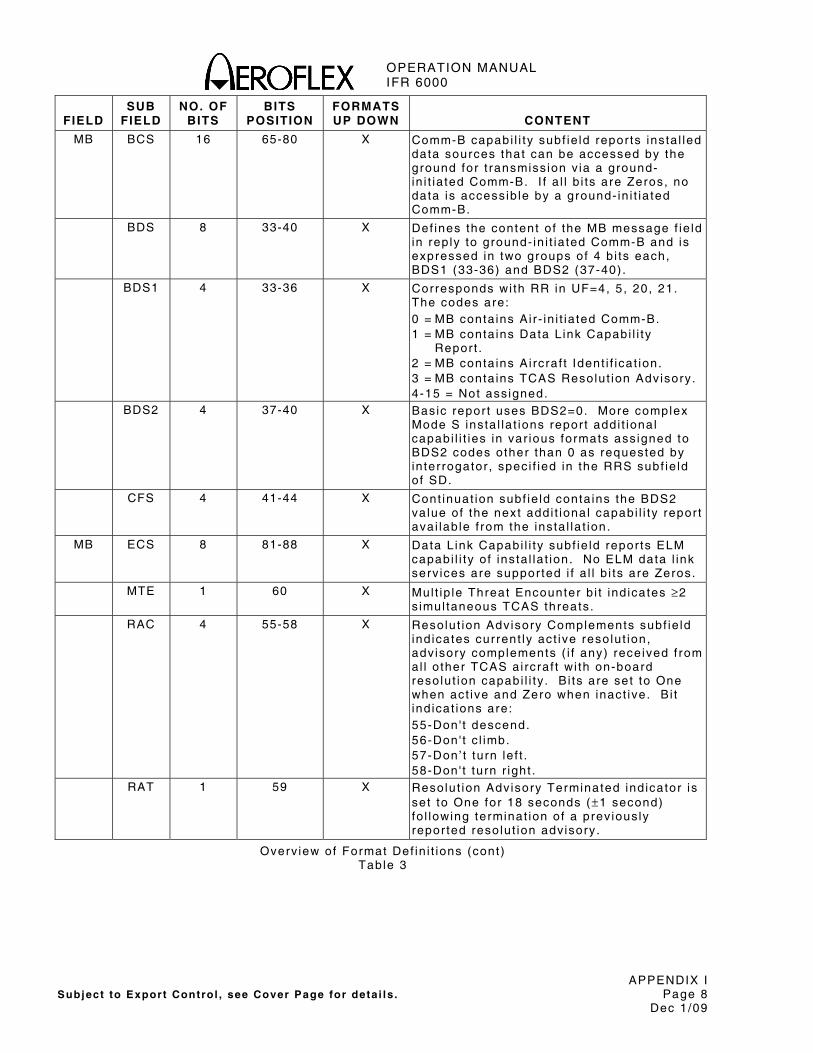
OPERATION MANUAL IFR 6000
APPENDIX I Subject to Export Control , see Cover Page for deta i ls . Page 8
Dec 1/09
FIELD
SUB FIELD
NO. OF BITS
BITS POSITION
FORMATS UP DOWN
CONTENT
MB BCS 16 65-80 X Comm-B capabi l i ty subf ie ld repor ts insta l led data sources that can be accessed by the ground for t ransmiss ion v ia a ground-in i t ia ted Comm-B. I f a l l b i ts are Zeros, no data is access ib le by a ground- in i t ia ted Comm-B.
BDS 8 33-40 X Def ines the content o f the MB message f ie ld in rep ly to ground- in i t ia ted Comm-B and is expressed in two groups of 4 b i ts each, BDS1 (33-36) and BDS2 (37-40) .
BDS1 4 33-36 X Corresponds wi th RR in UF=4, 5 , 20, 21. The codes are: 0 = MB conta ins Ai r - in i t ia ted Comm-B. 1 = MB conta ins Data L ink Capabi l i ty
Repor t . 2 = MB conta ins Ai rcraf t Ident i f icat ion. 3 = MB conta ins TCAS Resolut ion Advisory. 4-15 = Not ass igned.
BDS2 4 37-40 X Basic repor t uses BDS2=0. More complex Mode S insta l la t ions repor t addi t ional capabi l i t ies in var ious formats ass igned to BDS2 codes other than 0 as requested by in ter rogator , spec i f ied in the RRS subf ie ld of SD.
CFS 4 41-44 X Cont inuat ion subf ie ld conta ins the BDS2 va lue of the next addi t ional capabi l i ty repor t ava i lab le f rom the insta l la t ion.
MB ECS 8 81-88 X Data L ink Capabi l i ty subf ie ld repor ts ELM capabi l i ty o f ins ta l la t ion. No ELM data l ink serv ices are suppor ted i f a l l b i ts are Zeros.
MTE 1 60 X Mul t ip le Threat Encounter b i t ind icates ≥2 s imul taneous TCAS threats .
RAC 4 55-58 X Resolut ion Advisory Complements subf ie ld ind icates current ly act ive resolut ion, adv isory complements ( i f any) rece ived f rom al l o ther TCAS ai rcraf t wi th on-board resolut ion capabi l i ty . B i ts are set to One when act ive and Zero when inact ive. B i t ind icat ions are: 55-Don' t descend. 56-Don' t c l imb. 57-Don’ t turn le f t . 58-Don' t turn r ight .
RAT 1 59 X Resolut ion Advisory Terminated ind icator is set to One for 18 seconds (±1 second) fo l lowing terminat ion of a prev ious ly repor ted resolut ion adv isory .
Overv iew of Format Def in i t ions (cont) Table 3
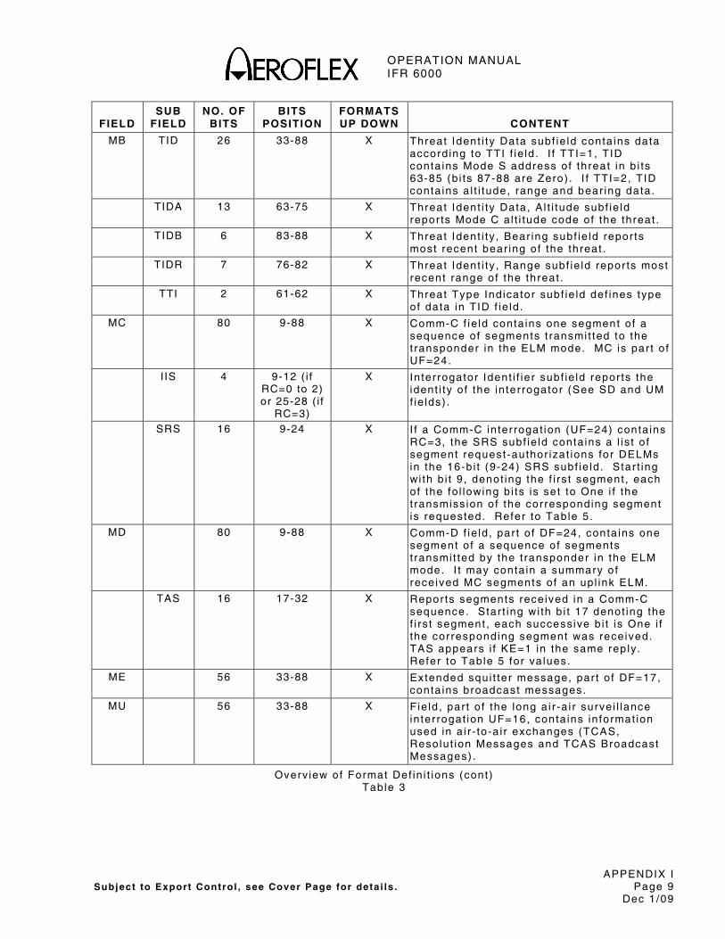
OPERATION MANUAL IFR 6000
APPENDIX I Subject to Export Control , see Cover Page for deta i ls . Page 9
Dec 1/09
FIELD
SUB FIELD
NO. OF BITS
BITS POSITION
FORMATS UP DOWN
CONTENT
MB TID 26 33-88 X Threat Ident i ty Data subf ie ld conta ins data accord ing to TTI f ie ld . I f TTI=1, TID conta ins Mode S address of threat in b i ts 63-85 (b i ts 87-88 are Zero) . I f TTI=2, TID conta ins a l t i tude, range and bear ing data.
TIDA 13 63-75 X Threat Ident i ty Data, A l t i tude subf ie ld repor ts Mode C a l t i tude code of the threat .
TIDB 6 83-88 X Threat Ident i ty , Bear ing subf ie ld repor ts most recent bear ing of the threat .
TIDR 7 76-82 X Threat Ident i ty , Range subf ie ld repor ts most recent range of the threat .
TTI 2 61-62 X Threat Type Ind icator subf ie ld def ines type of data in TID f ie ld .
MC 80 9-88 X Comm-C f ie ld conta ins one segment o f a sequence of segments t ransmi t ted to the t ransponder in the ELM mode. MC is par t o f UF=24.
I IS 4 9-12 ( i f RC=0 to 2) or 25-28 ( i f
RC=3)
X In ter rogator Ident i f ier subf ie ld repor ts the ident i ty o f the in ter rogator (See SD and UM f ie lds) .
SRS 16 9-24 X I f a Comm-C in ter rogat ion (UF=24) conta ins RC=3, the SRS subf ie ld conta ins a l is t o f segment request -author izat ions for DELMs in the 16-b i t (9-24) SRS subf ie ld . Star t ing wi th b i t 9 , denot ing the f i rs t segment , each of the fo l lowing b i ts is set to One i f the t ransmiss ion of the corresponding segment is requested. Refer to Table 5.
MD 80 9-88 X Comm-D f ie ld , par t o f DF=24, conta ins one segment o f a sequence of segments t ransmi t ted by the t ransponder in the ELM mode. I t may conta in a summary of rece ived MC segments of an up l ink ELM.
TAS 16 17-32 X Repor ts segments received in a Comm-C sequence. Star t ing wi th b i t 17 denot ing the f i rs t segment , each success ive b i t is One i f the corresponding segment was received. TAS appears i f KE=1 in the same reply . Refer to Table 5 for va lues.
ME 56 33-88 X Extended squi t ter message, par t o f DF=17, conta ins broadcast messages.
MU 56 33-88 X F ie ld , par t o f the long a i r -a i r surve i l lance in ter rogat ion UF=16, conta ins in format ion used in a i r - to-a i r exchanges (TCAS, Resolut ion Messages and TCAS Broadcast Messages) .
Overv iew of Format Def in i t ions (cont) Table 3

OPERATION MANUAL IFR 6000
APPENDIX I Subject to Export Control , see Cover Page for deta i ls . Page 10
Dec 1/09
FIELD
SUB FIELD
NO. OF BITS
BITS POSITION
FORMATS UP DOWN
CONTENT
MU CHC 3 47-49 X Cancel Hor izonta l Resolut ion Advisory Complement . In TCAS Resolut ion Messages t ransmi t ted by TCAS wi thout hor izonta l reso lut ion capabi l i ty , CHC is set to 0 . The codes are: 0 = No cancel la t ion. 1 = Cancel , don ' t turn le f t . 2 = Cancel , don ' t turn r ight . 3-7 = Not ass igned.
CVC 2 43-44 X Cancel Ver t ica l Resolut ion Advisory Complement . The codes are: 0 = No cancel la t ion. 1 = Cancel , don ' t descend. 2 = Cancel , don’ t c l imb. 3 = Not ass igned.
HRC 3 50-52 X Hor izonta l Resolut ion Advisory Complement . In TCAS Resolut ion Messages t ransmi t ted by TCAS wi thout hor izonta l reso lut ion capabi l i ty , HRC is set to 0 . The codes are: 0 = No hor izonta l reso lut ion adv isory
complement sent . 1 = In t ruder TCAS sense is turn le f t /do not
turn le f t . 2 = In t ruder TCAS sense is turn le f t /do not
turn r ight . 3-4 = Not ass igned. 5 = In t ruder TCAS sense is turn r ight /do not
turn le f t . 6 = In t ruder TCAS sense is turn r ight /do not
turn r ight . 7 = Not ass igned.
HSB 5 56-60 X Encoded Sense Bi ts for Hor izonta l Resolut ion Complements prov ide a par i ty coding f ie ld protect ing the s ix hor izonta l sense b i ts (CHC and HRC) and are used in TCAS I I I Resolut ion Messages.
MID 24 65-88 X Conta ins d iscrete address of in ter rogat ing a i rcraf t and is in TCAS Resolut ion Advisor ies Lock Requests , TCAS Resolut ion Messages and TCAS Broadcast Messages.
NOTE: TCAS Broadcast Message is sent a t 10-second in terva ls .
Overv iew of Format Def in i t ions (cont) Table 3

OPERATION MANUAL IFR 6000
APPENDIX I Subject to Export Control , see Cover Page for deta i ls . Page 11
Dec 1/09
FIELD
SUB FIELD
NO. OF BITS
BITS POSITION
FORMATS UP DOWN
CONTENT
MU MTB 1 42 X Mul t ip le Threat B i t ind icates more than one TCAS threat when set to One and no more than one threat when set to Zero.
UDS 8 33-40 X Def ines the content o f the MU message f ie ld and is expressed in two 4-b i t groups, UDS1 (33-36) and UDS2 (37-40) .
UDS1 4 33-36 X Is set to 3 for TCAS Resolut ion Messages and TCAS Broadcast Messages.
UDS2 4 37-40 X Is set to 0 for TCAS Resolut ion Messages or set to 2 for TCAS Broadcast Messages.
VRC 2 45-46 X Ver t ica l Resolut ion Advisory, Complement . The codes are: 0 = No ver t ica l reso lut ion adv isory
complement sent . 1 = Don' t descend. 2 = Don' t c l imb. 3 = Not ass igned.
VSB 4 61-64 X Encoded Sense Bi ts for Ver t ica l Resolut ion Complements prov ide a par i ty coding f ie ld to protect four ver t ica l sense b i ts (CVC and VRC) in a l l TCAS Resolut ion Messages. I f b i ts 43-46 do not agree wi th b i ts 61-64, the TCAS receiver assumes an error and d isregards message. B i ts are as fo l lows:
43 44 45 46 61 62 63 64
0 0 0 0 0 0 0 0 0 0 0 1 1 1 1 0 0 0 1 0 0 1 1 1 0 0 1 1 1 0 0 1 0 1 0 0 1 0 1 1 0 1 0 1 0 1 0 1 0 1 1 0 1 1 0 0 0 1 1 1 0 0 1 0 1 0 0 0 1 1 0 1 1 0 0 1 0 0 1 1 1 0 1 0 1 0 1 0 1 0 1 1 0 1 0 0 1 1 0 0 0 1 1 0 1 1 0 1 1 0 0 0 1 1 1 0 0 0 0 1 1 1 1 1 1 1 1 1
Overv iew of Format Def in i t ions (cont) Table 3
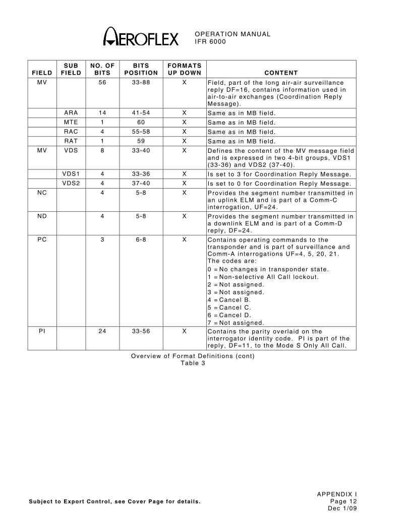
OPERATION MANUAL IFR 6000
APPENDIX I Subject to Export Control , see Cover Page for deta i ls . Page 12
Dec 1/09
FIELD
SUB FIELD
NO. OF BITS
BITS POSITION
FORMATS UP DOWN
CONTENT
MV 56 33-88 X F ie ld , par t o f the long a i r -a i r surve i l lance rep ly DF=16, conta ins in format ion used in a i r - to-a i r exchanges (Coord inat ion Reply Message) .
ARA 14 41-54 X Same as in MB f ie ld .
MTE 1 60 X Same as in MB f ie ld .
RAC 4 55-58 X Same as in MB f ie ld .
RAT 1 59 X Same as in MB f ie ld .
MV VDS 8 33-40 X Def ines the content o f the MV message f ie ld and is expressed in two 4-b i t groups, VDS1 (33-36) and VDS2 (37-40) .
VDS1 4 33-36 X Is set to 3 for Coord inat ion Reply Message.
VDS2 4 37-40 X Is set to 0 for Coord inat ion Reply Message.
NC 4 5-8 X Prov ides the segment number t ransmi t ted in an upl ink ELM and is par t o f a Comm-C in ter rogat ion, UF=24.
ND 4 5-8 X Prov ides the segment number t ransmi t ted in a downl ink ELM and is par t o f a Comm-D reply , DF=24.
PC 3 6-8 X Conta ins operat ing commands to the t ransponder and is par t o f surve i l lance and Comm-A in ter rogat ions UF=4, 5, 20, 21. The codes are: 0 = No changes in t ransponder s ta te. 1 = Non-se lect ive Al l Cal l lockout . 2 = Not ass igned. 3 = Not ass igned. 4 = Cancel B. 5 = Cancel C. 6 = Cancel D. 7 = Not ass igned.
PI 24 33-56 X Conta ins the par i ty over la id on the in ter rogator ident i ty code. PI is par t o f the rep ly , DF=11, to the Mode S Only Al l Cal l .
Overv iew of Format Def in i t ions (cont) Table 3

OPERATION MANUAL IFR 6000
APPENDIX I Subject to Export Control , see Cover Page for deta i ls . Page 13
Dec 1/09
FIELD
SUB FIELD
NO. OF BITS
BITS POSITION
FORMATS UP DOWN
CONTENT
PR 4 6-9 X F ie ld conta ins commands to the t ransponder spec i fy ing the rep ly probabi l i ty to the Mode S Only Al l Cal l in ter rogat ion, UF=11 conta in ing the PR. A command to d isregard any lockout s ta te can a lso be g iven. The ass igned codes are: 0 = Reply wi th probabi l i ty = 1. 1 = Reply wi th probabi l i ty = 1/2. 2 = Reply wi th probabi l i ty = 1/4. 3 = Reply wi th probabi l i ty = 1/8. 4 = Reply wi th probabi l i ty = 1/16. 5 ,6,7 = Do not Reply . 8 = Disregard lockout , rep ly wi th probabi l i ty
= 1. 9 = Disregard lockout , rep ly wi th probabi l i ty
= 1/2. 10 = Disregard lockout , rep ly wi th ,
probabi l i ty = 1/4. 11 = Disregard lockout , rep ly wi th
probabi l i ty = 1/8. 12 = Disregard lockout , rep ly wi th
probabi l i ty = 1/16. 13, 14, 15 = Do not rep ly . NOTE: On receipt o f a Mode S Only Al l Cal l
conta in ing a PR code other than 0 or 8 , t ransponder executes a random process and makes a rep ly dec is ion for the in ter rogat ion in accordance wi th the commanded probabi l i ty . Random occurrence of rep l ies enables in ter rogator to acqui re c lose ly spaced a i rcraf t when rep l ies would otherwise synchronously garb le each other .
RC 2 3-4 X Designates t ransmi t ted segment as in i t ia l , in termediate or f ina l i f coded 0, 1 or 2 respect ive ly . RC=3 is used to request Comm-D DELMs by the transponder. RC is par t o f Comm-C in ter rogat ion, UF=24.
Overv iew of Format Def in i t ions (cont) Table 3

OPERATION MANUAL IFR 6000
APPENDIX I Subject to Export Control , see Cover Page for deta i ls . Page 14
Dec 1/09
FIELD
SUB FIELD
NO. OF BITS
BITS POSITION
FORMATS UP DOWN
CONTENT
RI 4 14-17 X In format ion in DF=0, 16. The codes are: 0 = No on-board TCAS. 1 = Not ass igned. 2 = On-board TCAS wi th resolut ion
capabi l i ty inh ib i ted. 3 = On-board TCAS wi th ver t ica l -on ly
reso lut ion capabi l i ty . 4 = On-board TCAS wi th ver t ica l and
hor izonta l reso lut ion capabi l i ty . 5-7 = Not ass igned. 8 = No maximum ai rspeed data avai lab le . 9 = Ai rspeed is ≤75 k ts . 10 = Ai rspeed is >75 k ts and ≤150 k ts . 11 = Ai rspeed is >150 k ts and ≤300 k ts . 12 = Ai rspeed is >300 k ts and ≤600 k ts . 13 = Ai rspeed is >600 k ts and ≤1200 k ts . 14 = Ai rspeed is >1200 k ts . 15 = Not ass igned.
RL 1 9 X Command, sent in UF=0, 16; so l ic i ts DF=0 rep ly i f Zero and DF=16 rep ly i f One (on ly i f t ransponder is assoc iated wi th Ai rborne Col l is ion Avoidance System [ACAS] equipment) . Otherwise, in UF=0, Zero so l ic i ts DF=0 rep ly and One so l ic i ts no rep ly . In UF=16, Zero so l ic i ts DF=16 rep ly and One so l ic i ts no rep ly .
RR 5 9-13 X Conta ins length and content o f in ter rogator requested rep ly . RR is par t o f surve i l lance and Comm-A in ter rogat ions UF=4, 5, 20, 21.
RR CODE
REPLY LENGTH
MB CONTENT
0-15 Short N/A 16 Long Air in i t iated Comm-B 17 Long Data l ink capabi l i ty 18 Long Aircraft Ident i f icat ion 19 Long Resolut ion Advisor ies
20-31 Long Not Assigned
NOTE: I f f i rs t b i t o f RR code is One, dec imal equiva lent o f las t four b i ts o f RR code des ignates code for BDS1 in rep ly (ground in i t ia ted) . BDS2 is assumed to be Zero i f not spec i f ied by DI=7 and RRS.
Overv iew of Format Def in i t ions (cont) Table 3

OPERATION MANUAL IFR 6000
APPENDIX I Subject to Export Control , see Cover Page for deta i ls . Page 15
Dec 1/09
FIELD
SUB FIELD
NO. OF BITS
BITS POSITION
FORMATS UP DOWN
CONTENT
SD 16 17-32 X Conta ins cont ro l codes, as spec i f ied by the DI f ie ld a f fect ing t ransponder protocol and is par t o f surve i l lance and Comm-A in ter rogat ions UF=4, 5 , 20, 21.
I IS 4 17-20 X In ter rogator Ident i f ier subf ie ld conta ins the se l f - ident i f icat ion code of the in ter rogator and is numer ica l ly ident ica l to the I I code t ransmi t ted by the in ter rogator in Mode S Only Al l Cal ls . I IS codes are 0 through 15; I IS=0 is not a va l id in ter rogator ident i f ier for mul t is i te purposes. I IS is sent on ly when DI=0, 1 or 7 .
LOS 1 26 X Lockout subf ie ld , i f set to One, in i t ia tes a mul t is i te A l l Cal l lockout to Mode S Only Al l Cal ls (UF=11) f rom the In ter rogator ind icated in I IS of the in ter rogat ion. I f LOS is set to Zero, no change in lockout s ta te is commanded. LOS is sent on ly i f DI=1 or 7 .
LSS 1 23 X Lockout surve i l lance subf ie ld , i f set to One, shal l s ign i fy a mul t is i te lockout command f rom the in ter rogator ind icated in SIS. LSS set to zero shal l be used to s ign i fy that no change in lockout s ta te is commanded.
MBS 2 21-22 X Mul t is i te Comm-B subf ie ld , sent when DI=1, is ass igned the fo l lowing codes: 0 = No Comm-B act ion. 1 = Comm-B reservat ion. 2 = Comm-B c loseout .
MES 3 23-25 X Mul t is i te ELM subf ie ld , sent when DI=1, conta ins reservat ion and c loseout commands for ELM as fo l lows: 0 = No ELM act ion. 1 = Comm-C reservat ion. 2 = Comm-C c loseout . 3 = Comm-D reservat ion. 4 = Comm-D c loseout . 5 = Comm-C reservat ion and Comm-D
c loseout . 6 = Comm-C c loseout and Comm-D
reservat ion. 7 = Comm-C and Comm-D c loseouts .
Overv iew of Format Def in i t ions (cont) Table 3
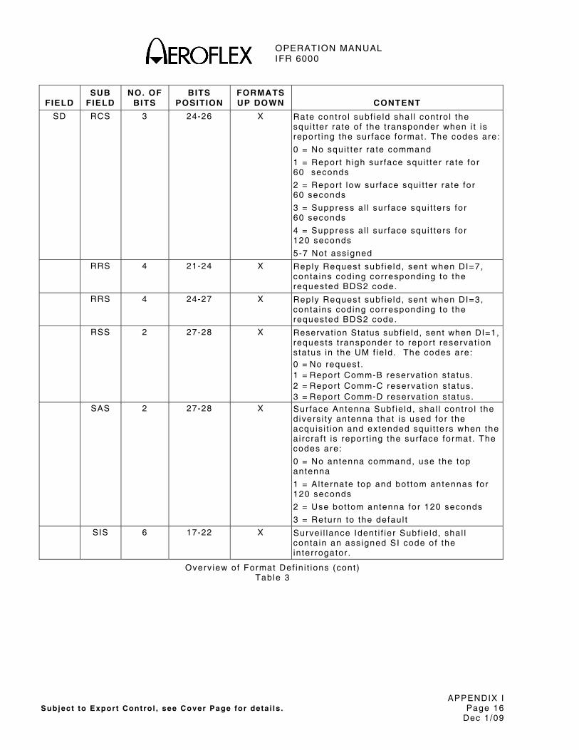
OPERATION MANUAL IFR 6000
APPENDIX I Subject to Export Control , see Cover Page for deta i ls . Page 16
Dec 1/09
FIELD
SUB FIELD
NO. OF BITS
BITS POSITION
FORMATS UP DOWN
CONTENT
SD RCS 3 24-26 X Rate cont ro l subf ie ld shal l cont ro l the squi t ter ra te of the t ransponder when i t is repor t ing the sur face format . The codes are:
0 = No squi t ter ra te command
1 = Repor t h igh sur face squi t ter ra te for 60 seconds
2 = Repor t low sur face squi t ter ra te for 60 seconds
3 = Suppress a l l sur face squi t ters for 60 seconds
4 = Suppress a l l sur face squi t ters for 120 seconds
5-7 Not ass igned
RRS 4 21-24 X Reply Request subf ie ld , sent when DI=7, conta ins coding corresponding to the requested BDS2 code.
RRS 4 24-27 X Reply Request subf ie ld , sent when DI=3, conta ins coding corresponding to the requested BDS2 code.
RSS 2 27-28 X Reservat ion Status subf ield, sent when DI=1, requests t ransponder to repor t reservat ion s tatus in the UM f ie ld . The codes are: 0 = No request . 1 = Repor t Comm-B reservat ion s tatus. 2 = Repor t Comm-C reservat ion s tatus. 3 = Repor t Comm-D reservat ion s tatus.
SAS 2 27-28 X Sur face Antenna Subf ie ld , shal l cont ro l the d ivers i ty antenna that is used for the acquis i t ion and extended squi t ters when the a i rcraf t is repor t ing the sur face format . The codes are:
0 = No antenna command, use the top antenna
1 = Al ternate top and bot tom antennas for 120 seconds
2 = Use bot tom antenna for 120 seconds
3 = Return to the defaul t
SIS 6 17-22 X Survei l lance Ident i f ier Subf ie ld , shal l conta in an ass igned SI code of the in ter rogator .
Overv iew of Format Def in i t ions (cont) Table 3
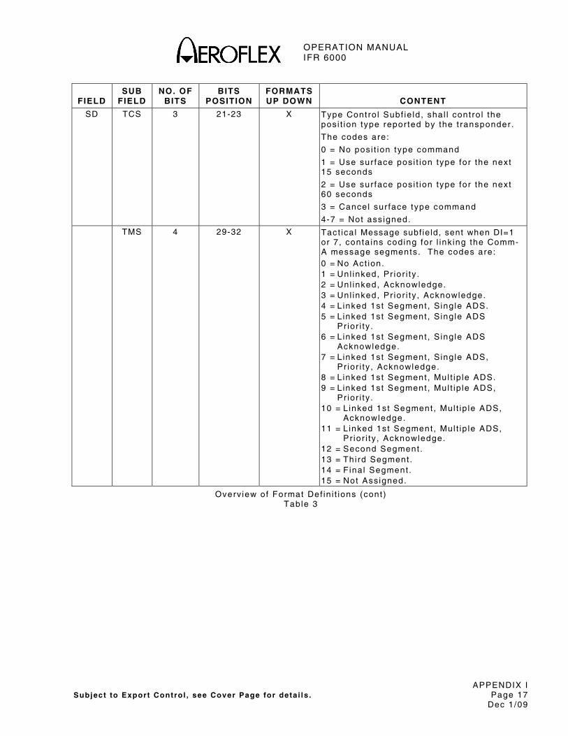
OPERATION MANUAL IFR 6000
APPENDIX I Subject to Export Control , see Cover Page for deta i ls . Page 17
Dec 1/09
FIELD
SUB FIELD
NO. OF BITS
BITS POSITION
FORMATS UP DOWN
CONTENT
SD TCS 3 21-23 X Type Contro l Subf ie ld , shal l cont ro l the pos i t ion type repor ted by the t ransponder .
The codes are:
0 = No pos i t ion type command
1 = Use sur face pos i t ion type for the next 15 seconds
2 = Use sur face pos i t ion type for the next 60 seconds
3 = Cancel sur face type command
4-7 = Not ass igned.
TMS 4 29-32 X Tact ica l Message subf ield, sent when DI=1 or 7 , conta ins coding for l ink ing the Comm-A message segments. The codes are: 0 = No Act ion. 1 = Unl inked, Pr ior i ty . 2 = Unl inked, Acknowledge. 3 = Unl inked, Pr ior i ty , Acknowledge. 4 = L inked 1st Segment , S ing le ADS. 5 = L inked 1st Segment , S ing le ADS
Pr ior i ty . 6 = L inked 1st Segment , S ing le ADS
Acknowledge. 7 = L inked 1st Segment , S ing le ADS,
Pr ior i ty , Acknowledge. 8 = L inked 1st Segment , Mul t ip le ADS. 9 = L inked 1st Segment , Mul t ip le ADS,
Pr ior i ty . 10 = L inked 1st Segment , Mul t ip le ADS,
Acknowledge. 11 = L inked 1st Segment , Mul t ip le ADS,
Pr ior i ty , Acknowledge. 12 = Second Segment . 13 = Thi rd Segment . 14 = F ina l Segment . 15 = Not Ass igned.
Overv iew of Format Def in i t ions (cont) Table 3

OPERATION MANUAL IFR 6000
APPENDIX I Subject to Export Control , see Cover Page for deta i ls . Page 18
Dec 1/09
FIELD
SUB FIELD
NO. OF BITS
BITS POSITION
FORMATS UP DOWN
CONTENT
SL 3 9-11 X Repor ts the current operat ing sens i t iv i ty leve l o f the TCAS uni t and is a par t o f a i r -a i r surve i l lance rep l ies, DF=0, 16. The codes are: 0 = No TCAS sensi t iv i ty leve l repor ted. 1 = TCAS operates at sens i t iv i ty leve l 1 . 2 = TCAS operates at sens i t iv i ty leve l 2 . 3 = TCAS operates at sens i t iv i ty leve l 3 . 4 = TCAS operates at sens i t iv i ty leve l 4 . 5 = TCAS operates at sens i t iv i ty leve l 5 . 6 = TCAS operates at sens i t iv i ty leve l 6 . 7 = TCAS operates at sens i t iv i ty leve l 7 . NOTE: The SL f ie ld has no meaning for
a i rcraf t wi th RI=0 (no on-board capabi l i ty to generate resolut ion, adv isor ies) .
UF 5 1-5 X The f i rs t f ie ld in a l l up l ink formats is the t ransmiss ion descr ip tor in a l l in ter rogat ions.
UM 6 14-19 X Conta ins t ransponder s ta tus readouts in rep l ies DF=4, 5 , 20, 21.
IDS 2 18-19 X Ident i f ier Designator subf ie ld repor ts the type of reservat ion made by the in ter rogator ident i f ied in I IS and corresponds wi th the RSS subf ie ld of SD. Ass igned coding is : 0 = No in format ion avai lab le. 1 = Comm-B reservat ion act ive. 2 = Comm-C reservat ion act ive. 3 = Comm-D reservat ion act ive.
I IS 4 14-17 X In ter rogator Ident i f ier subf ie ld repor ts the ident i ty o f the in ter rogator that has made a mul t is i te reservat ion.
VS 1 6 X Ind icates a i rcraf t is a i rborne when Zero or a i rcraf t is on the ground when One. VS is a par t o f DF=0, 16.
Overv iew of Format Def in i t ions (cont) Table 3

OPERATION MANUAL IFR 6000
APPENDIX I Subject to Export Control , see Cover Page for deta i ls . Page 19
Dec 1/09
B5 0 0 1 1
B6 0 1 0 1
B4 B3 B2 B1
0 0 0 0 P SP 0
0 0 0 1 A Q 1
0 0 1 0 B R 2
0 0 1 1 C S 3
0 1 0 0 D T 4
0 1 0 1 E U 5
0 1 1 0 F V 6
0 1 1 1 G W 7
1 0 0 0 H X 8
1 0 0 1 I Y 9
1 0 1 0 J Z
1 0 1 1 K
1 1 0 0 L
1 1 0 1 M
1 1 1 0 N
1 1 1 1 O
SP=SPACE code
6-Bi t Character Set for AIS Subf ie ld Table 4
SRS OR TAS SUBFIELD VALUE
OCTAL HEXADECIMAL NUMBER OF SEGMENTS
100000 8000 1
140000 C000 2
160000 E000 3
170000 F000 4
174000 F800 5
176000 FC00 6
177000 FE00 7
177400 FF00 8
177600 FF80 9
177700 FFC0 10
177740 FFE0 11
177760 FFF0 12
177770 FFF8 13
177774 FFFC 14
177776 FFFE 15
177777 FFFF 16
Val id Values for SRS and TAS Subf ie lds Table 5
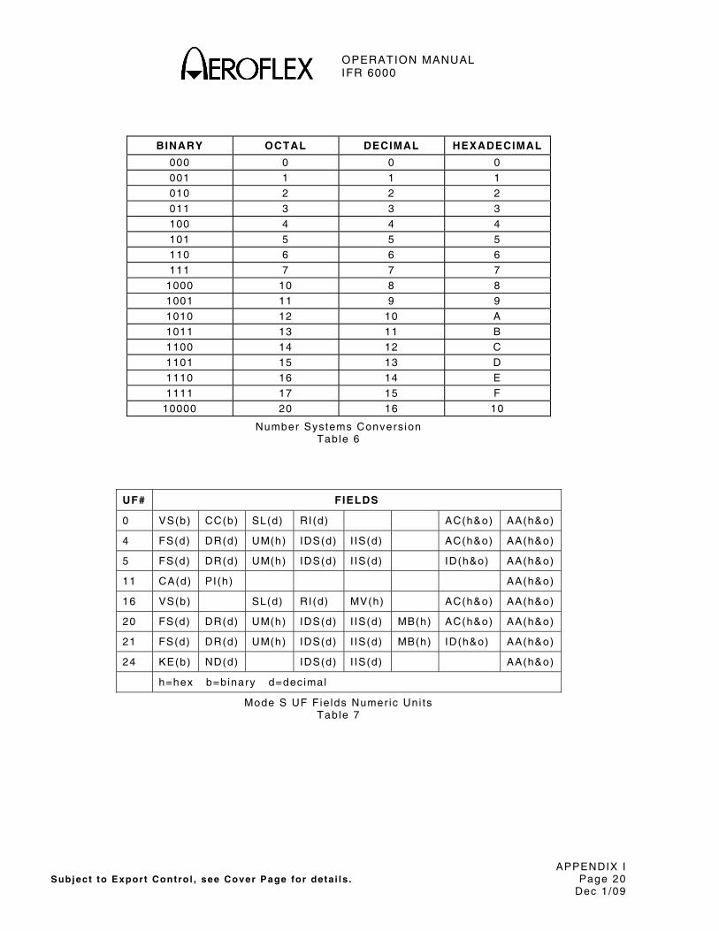
OPERATION MANUAL IFR 6000
APPENDIX I Subject to Export Control , see Cover Page for deta i ls . Page 20
Dec 1/09
BINARY OCTAL DECIMAL HEXADECIMAL
000 0 0 0
001 1 1 1
010 2 2 2
011 3 3 3
100 4 4 4
101 5 5 5
110 6 6 6
111 7 7 7
1000 10 8 8
1001 11 9 9
1010 12 10 A
1011 13 11 B
1100 14 12 C
1101 15 13 D
1110 16 14 E
1111 17 15 F
10000 20 16 10
Number Systems Convers ion Table 6
UF# FIELDS
0 VS(b) CC(b) SL(d) RI(d) AC(h&o) AA(h&o)
4 FS(d) DR(d) UM(h) IDS(d) I IS(d) AC(h&o) AA(h&o)
5 FS(d) DR(d) UM(h) IDS(d) I IS(d) ID(h&o) AA(h&o)
11 CA(d) PI(h) AA(h&o)
16 VS(b) SL(d) RI(d) MV(h) AC(h&o) AA(h&o)
20 FS(d) DR(d) UM(h) IDS(d) I IS(d) MB(h) AC(h&o) AA(h&o)
21 FS(d) DR(d) UM(h) IDS(d) I IS(d) MB(h) ID(h&o) AA(h&o)
24 KE(b) ND(d) IDS(d) I IS(d) AA(h&o)
h=hex b=binary d=decimal
Mode S UF Fie lds Numer ic Uni ts Table 7

OPERATION MANUAL IFR 6000
APPENDIX J Subject to Export Control , see Cover Page for deta i ls . Page 1
Dec 1/09
APPENDIX J - STANDARD ACCESSORIES
1. AUXILIARY EQUIPMENT
Refer to Appendix J , F igure 1.
ITEM DESCRIPTION
● DC Power Supply
Used to power the Test Set .
● Antenna
RF antenna used wi th Test Set when power accuracy is most cr i t ica l .
● Breakout Box
Prov ides means of access ing ind iv idual user in ter faces v ia s tandard connectors
● Antenna Shie ld
Used wi th Antenna Clamp Assembly to cover UUT Antenna not be ing tested.
● 12 in . Coaxia l Cable
Used to connect Test Set ANT Connector to Di rect ional Antenna ANT Connector .
ITEM DESCRIPTION
● 72 in . Coaxia l Cable
Used to connect the Test Set to the UUT.
● 5 A Fuse
Spare Fuse
● Power Cord (US Only)
Used to connect AC power f rom an external AC power source to AC PWR Connector .
● Power Cord (European)
Used to connect AC power f rom an external AC power source to AC PWR Connector .
Aux i l iary Equipment F igure 1

OPERATION MANUAL IFR 6000
APPENDIX J Subject to Export Control , see Cover Page for detai ls . Page 2
Dec 1/09
2. ANTENNA SHIELD PROCEDURE
Refer to Appendix J , F igure 2.
STEP PROCEDURE
1. Posi t ion Antenna Clamp Assembly ins ide the s lo t in the Antenna Shie ld Plate, a l ign ing capt ive screws in to the respect ive screw holes.
2 . T ighten capt ive screws.
STEP PROCEDURE
3. Cover UUT Antenna wi th Antenna Shie ld . Loosen Thumbscrews i f necessary.
NOTE: I t may be necessary to remove UUT Antenna Guard i f access to UUT Antenna is rest r ic ted.
4 . Secure Antenna Shie ld by t ightening thumbscrews.
ANTENNA SHIELDPLATE
THUMB SCREW
ANTENNA CLAMP ASSEMBLY
CAPTIVE SCREW
8107007
Antenna Shie ld F igure 2

OPERATION MANUAL IFR 6000
APPENDIX K Subject to Export Control , see Cover Page for deta i ls . Page 1
Dec 1/09
APPENDIX K - TARGET ACQUISITION TIME PROBABILITY TABLE
The fo l lowing tab le shows the probabi l i ty o f target acquis i t ion t ime increas ing by more than a speci f ied t ime ( in addi t ion to the normal two to three sec) . The tab le ind icates, for example, there is a 10% probabi l i ty the target acquis i t ion t ime increases by more than ten sec.
NOTE: The tab le on ly appl ies when test ing one UUT Antenna. Other UUT Antennas are sh ie lded, d isabled or out o f the l ine of s ight path wi th the IFR 6000 TCAS.
.
INCREASE IN TARGET ACQUISITION TIME
PROBABILITY PERCENTAGE
>3 sec 91%
>4 sec 76%
>5 sec 59%
>6 sec 44%
>7 sec 31%
>8 sec 22%
>9 sec 15%
>10 sec 10%
>11 sec 7%
>12 sec 4%
>13 sec 3%
>14 sec 2%
>15 sec 1%
>16 sec 0.7%
>17 sec 0.4%
>18 sec 0.3%
>19 sec 0.2%
>20 sec 0.1%
Target Acquis i t ion T ime Probabi l i ty Table 1
OPERATION MANUAL IFR 6000
APPENDIX K Subject to Export Control , see Cover Page for deta i ls . Page 2
Dec 1/09
THIS PAGE INTENTIONALLY LEFT BLANK.
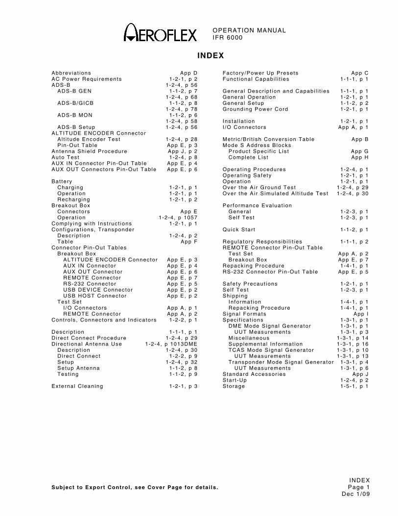
OPERATION MANUAL IFR 6000
INDEX Subject to Export Control , see Cover Page for deta i ls . Page 1
Dec 1/09
INDEX Abbrev ia t ions App D AC Power Requi rements 1-2-1 , p 2 ADS-B 1-2-4 , p 56 ADS-B GEN 1-1-2 , p 7 1 -2-4 , p 68 ADS-B/GICB 1-1-2 , p 8 1 -2-4 , p 78 ADS-B MON 1-1-2 , p 6 1 -2-4 , p 58 ADS-B Setup 1-2-4 , p 56 ALTITUDE ENCODER Connec tor A l t i t ude Encoder Tes t 1-2-4 , p 28 P in-Out Tab le App E , p 3 Antenna Sh ie ld Procedure App J , p 2 Auto Tes t 1-2-4 , p 8 AUX IN Connec tor P in-Out Tab le App E , p 4 AUX OUT Connec tors P in-Out Tab le App E , p 6 Bat tery Charg ing 1-2-1 , p 1 Operat ion 1-2-1 , p 1 Recharg ing 1-2-1 , p 2 Breakout Box Connec tors App E Operat ion 1-2-4 , p 1057 Comply ing wi th Ins t ruc t ions 1-2-1 , p 1 Conf igura t ions , Transponder Desc r ip t ion 1-2-4 , p 2 Tab le App F Connec tor P in-Out Tab les Breakout Box ALTITUDE ENCODER Connec tor App E , p 3 AUX IN Connec tor App E , p 4 AUX OUT Connec tor App E , p 6 REMOTE Connec tor App E , p 7 RS-232 Connec tor App E , p 5 USB DEVICE Connec tor App E , p 2 USB HOST Connec tor App E , p 2 Tes t Set I /O Connec tors App A , p 1 REMOTE Connec tor App A , p 2 Cont ro ls , Connec tors and Ind icators 1-2-2 , p 1 Desc r ip t ion 1-1-1 , p 1 D i rec t Connec t Procedure 1-2-4 , p 29 Di rec t iona l Antenna Use 1-2-4 , p 1013DME Descr ip t ion 1-2-4 , p 30 D i rec t Connec t 1-2-2 , p 9 Setup 1-2-4 , p 32 Setup Antenna 1-1-2 , p 8 Tes t ing 1-1-2 , p 9 Ex terna l C lean ing 1-2-1 , p 3
Fac tory /Power Up Presets App C Func t iona l Capab i l i t ies 1-1-1 , p 1 Genera l Desc r ip t ion and Capabi l i t ies 1-1-1 , p 1 Genera l Operat ion 1-2-1 , p 1 Genera l Setup 1-1-2 , p 2 Grounding Power Cord 1-2-1 , p 1 Ins ta l la t ion 1-2-1 , p 1 I /O Connec tors App A , p 1 Met r i c /Br i t i sh Convers ion Tab le App B Mode S Address B locks Produc t Spec i f i c L is t App G Comple te L is t App H Operat ing Procedures 1-2-4 , p 1 Operat ing Safe ty 1-2-1 , p 1 Operat ion 1-2-1 , p 1 Over the A i r Ground Tes t 1-2-4 , p 29 Over the A i r S imula ted A l t i t ude Tes t 1 -2-4 , p 30 Per formance Eva luat ion Genera l 1-2-3 , p 1 Se l f Tes t 1-2-3 , p 1 Quick S tar t 1 -1-2 , p 1 Regu la tory Respons ib i l i t ies 1-1-1 , p 2 REMOTE Connec tor P in-Out Tab le Tes t Set App A , p 2 Breakout Box App E , p 7 Repack ing Procedure 1-4-1 , p 1 RS-232 Connec tor P in-Out Tab le App E , p 5 Safe ty Precaut ions 1-2-1 , p 1 Se l f Tes t 1-2-3 , p 1 Sh ipp ing In format ion 1-4-1 , p 1 Repack ing Procedure 1-4-1 , p 1 S igna l Formats App I Spec i f i ca t ions 1-3-1 , p 1 DME Mode S igna l Generator 1-3-1 , p 1 UUT Measurements 1-3-1 , p 3 M isce l laneous 1-3-1 , p 14 Supplementa l In format ion 1-3-1 , p 16 TCAS Mode S igna l Generator 1-3-1 , p 10 UUT Measurements 1-3-1 , p 13 Transponder Mode S igna l Generator 1-3-1 , p 4 UUT Measurements 1-3-1 , p 6 S tandard Accessor ies App J S tar t -Up 1-2-4 , p 2 S torage 1-5-1 , p 1

OPERATION MANUAL IFR 6000
INDEX Subject to Export Control , see Cover Page for detai ls . Page 2
Dec 1/09
Target Acqu is i t ion T ime App K Tes t L is t 1 -2-4 , p 11 TCAS Mode 1-2-4 , p .35 Broadcas t Moni tor 1-2-4 , p 49 Desc r ip t ion 1-2-4 , p 35 Moni tor Sc reens 1-2-4 , p 47 Operat ion Concept 1-2-4 , p 35 Recommended Tes t Procedure 1-2-4 , p 54 Sc reen 1-2-4 , p 42 Setup 1-2-4 , p 38 Setup Antenna 1-1-2 , p 10 Setup Scenar io Data Sc reen 1-2-4 , p 45 Surve i l lance Moni tor 1-2-4 , p 47 Tes t ing 1-1-2 , p 11 1 -2-4 , p 38 T IS Mode Genera l desc r ip t ion 1-2-4 , p 99 Mode 1-2-4 , p 99 Setup 1-2-4 , p 99 Setup Antenna 1-1-2 , p 12 Setup Di rec t Connec t 1-1-2 , p 13 Tes t ing 1-1-2 , p 13 USB DEVICE Connec tor App E , p 2 USB HOST Connec tor P in-Out Tab le App E , p 2 XPDR A l t i t ude Encoder 1-2-4 , p 28 Auto Tes t 1-2-4 , p 8 Conf igura t ions 1-2-4 , p 2 Desc r ip t ion 1-2-4 , p 1 D i rec t Connec t Procedure 1-1-2 , p 4 1 -2-4 , p 29 Over The A i r Tes ts 1-2-4 , p 29 Setup 1-2-4 , p 3 Setup Antenna 1-1-2 , p 2 Tes t L is t 1 -2-4 , p 10 Tes t ing 1-1-2 , p 5

OPERATION MANUAL IFR 6000
FOR QUALIFIED SERVICE PERSONNEL ONLY
BATTERY/FUSE INSTRUCTIONS

OPERATION MANUAL IFR 6000
THIS PAGE INTENTIONALLY LEFT BLANK.

OPERATION MANUAL IFR 6000
SAFETY FIRST: TO ALL SERVICE PERSONNEL
REFER ALL SERVICING OF UNIT TO QUALIFIED TECHNICAL PERSONNEL.
WARNING: USING THIS EQUIPMENT IN A MANNER NOT SPECIF IED BY THE ACCOMPANYING DOCUMENTATION MAY IMPAIR THE SAFETY PROTECTION PROVIDED BY THE EQUIPMENT.
CASE, COVER OR PANEL REMOVAL
Opening the Case Assembly exposes the techn ic ian to e lec t r i ca l hazards that can resu l t in e lec t r i ca l shock or equ ipment damage.
SAFETY IDENTIFICATION IN TECHNICAL MANUAL
This manual uses the fo l lowing terms to draw at tent ion to poss ib le safe ty hazards , that may ex is t when operat ing or serv ic ing th is equ ipment .
CAUTION: THIS TERM IDENTIFIES CONDITIONS OR ACTIVIT IES THAT, IF IGNORED, CAN RESULT IN EQUIPMENT OR PROPERTY DAMAGE (E .G. , F IRE) .
WARNING: THIS TERM IDENTIFIES CONDITIONS OR ACTIVIT IES THAT, IF IGNORED, CAN RESULT IN PERSONAL INJURY OR DEATH.
SAFETY SYMBOLS IN MANUALS AND ON UNITS
CAUTION: Refer to accompany ing documents . (Th is symbol re fers to spec i f i c CAUTIONS represented on the un i t and c lar i f ied in the tex t . )
AC OR DC TERMINAL: Termina l that may supp ly or be supp l ied wi th ac or dc vo l tage.
DC TERMINAL: Termina l that may supp ly or be supp l ied wi th dc vo l tage.
AC TERMINAL: Termina l that may supp ly or be supp l ied wi th ac or a l te rnat ing vo l tage.
EQUIPMENT GROUNDING PRECAUTION
Improper ground ing o f equ ipment can resu l t in e lec t r i ca l shock .
USE OF PROBES
Check spec i f i ca t ions for the max imum vo l tage, cur rent and power ra t ings o f any connec tor on the Tes t Set before connec t ing i t w i th a probe f rom a termina l dev ice. Be sure the termina l dev ice per forms wi th in these spec i f i ca t ions before us ing i t fo r measurement , to prevent e lec t r i ca l shock or damage to the equ ipment .
POWER CORDS
Power cords mus t not be f rayed, broken nor expose bare wi r ing when operat ing th is equ ipment .
USE RECOMMENDED FUSES ONLY
Use on ly fuses spec i f i ca l l y recommended for the equ ipment a t the spec i f ied cur rent and vo l tage ra t ings .
WARNING: THE IFR 6000 USES A L ITHIUM ION BATTERY PACK. THE FOLLOWING WARNINGS CONCERNING LITHIUM ION BATTERIES MUST BE HEEDED:
● DO NOT RECHARGE OUTSIDE THE IFR 6000.
● DO NOT CRUSH, INCINERATE OR DISPOSE OF IN NORMAL WASTE.
● DO NOT SHORT CIRCUIT OR FORCE DISCHARGE AS THIS MIGHT CAUSE THE BATTERY TO VENT, OVERHEAT OR EXPLODE.
OPERATION MANUAL IFR 6000
CAUTION: INTEGRATED CIRCUITS AND SOLID STATE DEVICES SUCH AS MOS FETS, ESPECIALLY CMOS TYPES, ARE SUSCEPTIBLE TO DAMAGE BY ELECTROSTATIC DISCHARGES RECEIVED FROM IMPROPER HANDLING, THE USE OF UNGROUNDED TOOLS AND IMPROPER STORAGE AND PACKAGING. ANY MAINTENANCE TO THIS UNIT MUST BE PERFORMED WITH THE FOLLOWING PRECAUTIONS:
● BEFORE USE IN A CIRCUIT, KEEP ALL LEADS SHORTED TOGETHER EITHER BY THE USE OF VENDOR-SUPPLIED SHORTING SPRINGS OR BY INSERTING LEADS INTO A CONDUCTIVE MATERIAL.
● WHEN REMOVING DEVICES FROM THEIR CONTAINERS, GROUND THE HAND BEING USED WITH A CONDUCTIVE WRISTBAND.
● T IPS OF SOLDERING IRONS AND/OR ANY TOOLS USED MUST BE GROUNDED.
● DEVICES MUST NEVER BE INSERTED INTO NOR REMOVED FROM CIRCUITS WITH POWER ON.
● PC BOARDS, WHEN TAKEN OUT OF THE SET, MUST BE LAID ON A GROUNDED CONDUCTIVE MAT OR STORED IN A CONDUCTIVE STORAGE BAG. REMOVE ANY BUILT-IN POWER SOURCE, SUCH AS A BATTERY, BEFORE LAYING PC BOARDS ON A CONDUCTIVE MAT OR STORING IN A CONDUCTIVE BAG.
● PC BOARDS, IF BEING SHIPPED TO THE FACTORY FOR REPAIR, MUST BE PACKAGED IN A CONDUCTIVE BAG AND PLACED IN A WELL-CUSHIONED SHIPPING CONTAINER.
CAUTION
THIS EQUIPMENT CONTAINS PARTS
SENSITIVE TO DAMAGE
BY ELECTROSTATIC DISCHARGE (ESD)
CAUTION: S IGNAL GENERATORS CAN BE A SOURCE OF ELECTROMAGNETIC INTERFERENCE (EMI ) TO COMMUNICATION RECEIVERS. SOME TRANSMITTED SIGNALS CAN CAUSE DISRUPTION AND INTERFERENCE TO COMMUNICATION SERVICES OUT TO A DISTANCE OF SEVERAL MILES. USERS OF THIS EQUIPMENT SHOULD SCRUTINIZE ANY OPERATION THAT RESULTS IN RADIATION OF A S IGNAL (DIRECTLY OR INDIRECTLY) AND ENSURE COMPLIANCE WITH INSTRUCTIONS IN FAA CIRCULAR AC 170-6C, DATED FEBRUARY 19, 1981.

OPERATION MANUAL IFR 6000
Subject to Export Control , see Cover Page for deta i ls . Page 1 Dec 1/09
FOR QUALIFIED SERVICE PERSONNEL ONLY
FUSE REPLACEMENT
Refer to F igure 1.
STEP PROCEDURE
1. Ver i fy the IFR 6000 is OFF and not connected to AC power.
2 . Fu l ly loosen two capt ive screws in the two lower bumpers and remove the bumpers.
3 . Fu l ly loosen f ive capt ive screws and l i f t the Bat tery Cover f rom the Case Assembly .
4 . Replace fuse:
5 A, 32 Vdc, Type F (Mini Blade Fuse)
(Aerof lex PN: 5106-0000-057)
CAUTION: FOR CONTINUOUS PROTECTION AGAINST FIRE, REPLACE ONLY WITH FUSES OF THE SPECIFIED VOLTAGE AND CURRENT RATINGS.
5 . Insta l l the Bat tery Cover on the Case Assembly and t ighten the f ive capt ive screws (8 in / lbs. ) .
6 . Insta l l the two lower bumpers and t ighten the two capt ive screws in each bumper (8 in / lbs. ) .
BATTERY REPLACEMENT
Refer to F igure 1.
STEP PROCEDURE
1. Ver i fy the IFR 6000 is OFF and not connected to AC power.
2 . Fu l ly loosen two capt ive screws in the two lower bumpers and remove the bumpers.
3 . Fu l ly loosen f ive capt ive screws and l i f t the Bat tery Cover f rom the Case Assembly .
4 . Disconnect the wi re harness connect ing the bat tery to the Test Set and remove the bat tery .
5 . Insta l l new bat tery and reconnect the wi re harness.
6 . Insta l l the Bat tery Cover on the Case Assembly and t ighten the f ive capt ive screws (8 in / lbs. ) .
7 . Insta l l the two lower bumpers and t ighten the two capt ive screws in each bumper (8 in / lbs. ) .
WARNING: DISPOSE OF OLD BATTERY ACCORDING TO LOCAL STANDARD SAFETY PROCEDURES.
CAUTION: REPLACE ONLY WITH THE BATTERY SPECIFIED BY AEROFLEX. DO NOT ATTEMPT TO INSTALL A NON-RECHARGEABLE BATTERY.

OPERATION MANUAL IFR 6000
Subject to Export Control , see Cover Page for deta i ls . Page 2 Dec 1/09
05805
CAPTIVE SCREWS
BATTERY COVER
WIRE HARNESS
BATTERY
FUSE(5 EA)
(ONE ON EACH SIDE)CAPTIVE SCREWS
BUMPER
BUMPER
CAPTIVE SCREWS(ONE ON EACH SIDE)
Bat tery and Fuse Replacement F igure 1

CHINA / Beijing Tel: [+86] (10) 6539 1166 Fax: [+86] (10) 6539 1778
CHINA / Shanghai Tel: [+86] (21) 5109 5128 Fax: [+86] (21) 5150 6112
FINLAND Tel: [+358] (9) 2709 5541 Fax: [+358] (9) 804 2441
FRANCE Tel: [+33] 1 60 79 96 00 Fax: [+33] 1 60 77 69 22
GERMANY Tel: [+49] 8131 2926-0 Fax: [+49] 8131 2926-130
HONG KONG Tel: [+852] 2832 7988 Fax: [+852] 2834 5364
INDIA Tel: [+91] 80 51150 4501 Fax: [+91] 80 5115 4502
KOREA Tel: [+82] (2) 3424 2719 Fax: [+82] (2) 3424 8620
SCANDINAVIA Tel: [+45] 9614 0045 Fax: [+45] 9614 0047
SPAIN Tel: [+34] (91) 640 11 34 Fax: [+34] (91) 640 06 40
UK / Burnham Tel: [+44] (0) 1628 604455 Fax: [+44] (0) 1628 662017
UK / Cambridge Tel: [+44] (0) 1763 262277 Fax: [+44] (0) 1763 285353
UK / Stevenage Tel: [+44] (0) 1438 742200 Fax: [+44] (0) 1438 727601
Freephone: 0800 282388
USA Tel: [+1] (316) 522 4981 Fax: [+1] (316) 522 1360
Toll Free: 800 835 2352
Our passion for performance is defined by three attributes represented by these three icons:
solution-minded, performance-driven, customer-focused.
As we are always seeking to improve our products, the information in
this document gives only a general indication of the product capacity,
performance and suitability, none of which shall form part of any
contract. We reserve the right to make design changes without notice.
EXPORT CONTROL WARNING: This document contains controlled technology or technical data under the jurisdiction of the Export Administration Regulations (EAR), 15 CFR 730-774. It cannot be transferred to any foreign third party without the specific prior approval of the U.S. Department of Commerce Bureau of Industry and Security BIS). Violations of these regulations are punishable byfine, imprisonment, or both.