ifm Automation Technology for the Food Industry Catalogue 2015 ...

2010
fluid sensors and diagnostic
systems
bus, identification
and control systems
position sensors
and objectrecognition
7844 xMade in Germany7844 xMade in Germany
ifm efector – close to you!


visit our website:
www.ifmefector.com.au
We
rese
rve
the
right
to
mak
e te
chni
cal a
ltera
tions
with
out
prio
r no
tice.
04/
10
Over 70 locations worldwide – at a glance at
Australia
ifm efector pty ltd.P.O. Box 4084Suite 3, 745 Springvale RoadMulgrave VIC 3170Tel. 1300 365 088Fax 1300 365 [email protected]
New Zealand
ifm efector pty ltd.Unit B, 20 Cain RoadPenrose, AucklandTel. +64 / 95 79 69 91Fax +64 / 95 79 92 [email protected]/nz
www.ifm.com
ifm efector – close to you!

ifm – the company 6 - 7
General information 8 - 9
List of articles / approvals 10 - 15
Inductive sensors 17 - 37
Capacitive sensors 39 - 47
Cylinder sensors 49 - 56
Safety technology 59 - 62
Valve sensors 65 - 67
Photoelectric sensors infrared / redlight 69 - 84
Photoelectric sensors laser 87 - 91
Photoelectric sensors fibre optics 93 - 98
Photoelectric sensors specific systems 101 - 106
Object recognition 109 - 112
Encoders 115 - 119
Evaluation systems 121 - 125
Level sensors 127 - 135
Flow sensors 137 - 150
Pressure sensors 153 - 164
Temperature sensors 167 - 180
Diagnostic systems 183 - 188
Bus system AS-interface 191 - 206
Multicode reading systems 209 - 211
RF-identification systems 213 - 216
Power supplies 219 - 222
Connection technology 225 - 234
ifm – worldwide addresses 236 - 237

The company in your vicinity.
State-of-the-art communication.
With the right address – www.ifm.com – only a mouse click separates you from theworld of automation technology. See the power of our products in interactive repre-sentations. Gain an impression with 3-dimension-al views of our units. DownloadCAD drawings for direct integration in your applications. And one more innovationon the internet: The e-shop – already available in many countries. Order online – noweven faster, more convenient and reliable.
We are there for you.
Close contact with our customers is part of our success. Therefore we have consi-stently developed our sales network right from the start. Today ifm electronic isrepresented in more than 70 countries – close to you! With application advice andservice at the heart of our operation. For the introduction of new products and tech-nologies we support you with workshops and seminars in our training centres or inyour plant.
Security by success.
Since its foundation in 1969 ifm electronic has constantly grown, now having morethan 3300 employees worldwide, and achieved a turnover of EUR 340 million in2009. This success gives you the security of having a reliable partner for the imple-mentation of your automation projects. Comprehensive service and a warranty of upto 5 years on standard units are just two examples of this reliability.
1980 1990
200
100
0
300
2000
400
1970
500
sale
s de
velo
pmen
t in
mill
ion
EU
R
Turnoverdevelopmentsince 1970.
ifm – the company
6www.ifm.com
ifm – the company
7
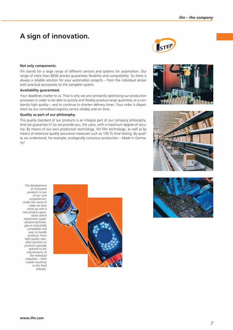
A sign of innovation.
Not only components.
ifm stands for a large range of different sensors and systems for automation. Ourrange of more than 8000 articles guarantees flexibility and compatibility. So there isalways a reliable solution for your automation projects – from the individual sensorwith practical accessories to the complete system.
Availability guaranteed.
Your deadlines matter to us. That is why we are constantly optimising our productionprocesses in order to be able to quickly and flexibly produce large quantities at a con-stantly high quality – and to continue to shorten delivery times. Your order is dispat-ched via our centralised logistics centre reliably and on time.
Quality as part of our philosophy.
The quality standard of our products is an integral part of our company philosophy.And we guarantee it! So we provide you, the users, with a maximum degree of secu-rity: By means of our own production technology, ifm film technology, as well as bymeans of extensive quality assurance measures such as 100 % final testing. By quali-ty we understand, for example, ecologically conscious production – Made in Germa-ny!
The developmentof innovative
products is oneof our core
competences.Under the name of
i-step we havecome up with a
new product gene-ration which
implements sophi-sticated technolo-gies in industrially
compatible andeasy to handleproducts. From
high-quality stan-dard solutions to
products speciallytailored to the
requirements ofthe individual
industries – frommobile machines
to the foodindustry.
www.ifm.com

www.ifm.comInformation around the clock andaround the globe in 22 languages on the internet.
• Information
- product innovations- company news- exhibition info- locations- jobs
• Documentation
- data sheets- operating instructions- manuals- approvals- CAD data
• Communication*
- request for documents- recall service- live advice- newsletter
• Selection
- interactive product selection aids- configuration tools- data sheet direct
• Animation
- virtual product animations- flash movies (video sequences)
• Application
- applications- product recommendations- calculation aids
• Transaction*
- e-shop processing- e-procurement catalogues- B2B services
*Some offered information is available country-specific
General information
8www.ifm.com

General information
9
Convenient order processingvia the e-shop** on the internet.
Secured authentication
Customer-related priceindication
Real time availability check
Personal product favourites
Online parcel tracking
Individual order history
Convenient quick input form
Simple order processing
Management of shippingaddresses
Confirmations by e-mail
** Already available in many countries.
www.ifm.com

List of articles / approvals
10www.ifm.com
Orderno.
Approvals Cataloguepage
AC002S CE, CUL 197
AC004S CE, CUL 197
AC005S CE, CUL 197
AC007S CE, CUL 197
AC009S CE, CRUUS 197
AC010S CE, CSA, UL 198
AC012S CE 198
AC015S CE, CRUUS 198
AC030S CE, CUL 197
AC031S CE 197
AC032S CE 197
AC1144 CE 199
AC1146 CE 193
AC1147 CE 193
AC1212 CE, CUL 194
AC1218 CE, CRUUS 194
AC1220 CE 194
AC1221 CE 194
AC1236 CE, CUL 194
AC1244 CE, CUL 194
AC1326 CE, CUL 193
AC1327 CE, CUL 193
AC1337 CE, CUL 193
AC1354 CE, CUL 193
AC1375 CE, CUL 193
AC1376 CE, CUL 193
AC2086 CE 195
AC2216 CE, CUL 194
AC2225 CE 193
AC2251 CE, CRUUS 194
AC2252 CE, CRUUS 194
AC2254 CE, CRUUS 194
AC2257 CE, CRUUS 194
AC2264 CE, CRUUS 194
AC2411 CE 195
AC2412 CE 196
AC2417 CE 195
AC2451 CE 195
AC2452 CE 196
AC2457 CE, CUL 195
AC2729 CE, CRUUS 194
AC2730 195
AC2900 CE, CUL 196
AC2904 CE, CUL 196
AC2910 CE, CUL 196
AC2916 CE, CUL 196
AC3000 200
AC4000 CE 200
AC4002 CE 200
AC4007 200
Orderno.
Approvals Cataloguepage
AC4008 200
AC5000 CUL 196
AC5003 CUL 196
AC5014 196
AC5015 196
AC5031 197, 199
AC5204 CE, CUL 195
AC5208 CE, CUL 195
AC5214 CE, CUL 195
AC5215 CE, CUL 195
AC5222 CE, CUL 195
AC5228 CE 197
AC5235 CE, CUL 195
AC5246 CE 197
DD2003 CE, CUL 123
DI0001 CE 123
DI5001 CE 123
DI5009 CE 123
DI6001 CE, CUL 123
DN1030 CE 221
DN1031 CE 221
DN2013 CE, CUL 221
DN2014 CE, CUL 221
DN2032 CE, CUL 221
DN2033 CE, CUL 221
DN2035 CE, CUL 221
DN2036 CE, CUL 221
DN3011 CE, CRUUS, CUL 221
DN3012 CE, CRUUS, CUL 221
DTA100 CE, CUL 198, 215
DTA300 CE, CUL 198, 215
DX2003 CE 123
E10017 159, 173, 29
E10191 228
E10200 228
E10734 28
E10735 28, 43
E10736 124, 28, 44
E10737 124, 28, 44
E11030 44
E11031 44
E11032 44
E11033 44
E11034 44
E11036 44
E11047 29
E11048 29
E11078 44
E11220 230
E11221 230
Orderno.
Approvals Cataloguepage
E11223 230
E11224 230
E11232 111, 228
E11248 CRUUS 228
E11249 CRUUS 228
E11495 CRUUS 230
E11496 CRUUS 230
E11498 CRUUS 230
E11499 CRUUS 230
E11504 CRUUS 228
E11505 CRUUS 228
E11508 CRUUS 227
E11509 CRUUS 227
E11521 28
E11530 29
E11531 29
E11533 29
E11534 29
E11572 185
E11664 185
E11697 228
E11796 54
E11797 54
E11798 54
E11799 54
E11801 54
E11816 53
E11817 53
E11818 53
E11819 53
E11820 53
E11821 53
E11822 53
E11823 53
E11877 53
E11914 54
E11928 54
E11929 61
E11958 54
E11959 54
E11960 54
E11961 54
E12004 54
E12153 45
E12208 67
E12209 67
E19503 29
E20004 77
E20005 77
E20600 96
List of articles / approvals
11www.ifm.com
Orderno.
Approvals Cataloguepage
E20615 95
E20639 95
E20718 29, 44
E20722 104, 90
E20738 228
E20765 96
E20767 96
E20768 96
E20773 96
E20774 96
E20860 29
E20861 29
E20870 29, 44
E20873 29, 44
E20874 29, 44
E20903 78
E20907 78
E20911 78
E20915 78
E20939 111, 112
E20941 111, 211
E20952 111
E20953 77
E20954 77
E20956 77
E20965 78
E20969 78
E20974 78, 90
E20984 78
E20993 89
E20994 89
E21015 78
E21084 79
E21087 104, 79
E21088 215, 79
E21117 79
E21120 79
E21125 78
E21126 78
E21166 111, 211
E21200 78
E21237 CE 78
E2D101 104, 90
E2D110 111, 211
E2D200 111
E2I200 211
E30006 132, 159
E30007 132, 160
E30016 174
E30017 174
Orderno.
Approvals Cataloguepage
E30018 174
E30047 174
E30052 FDA 132, 161
E30055 EHEDG 174
E30056 EHEDG 174
E30064 161
E30089 174
E30090 174
E30094 159, 175
E30098 185
E30104 132, 159
E30112 111, 186
E30115 187
E30116 160
E30122 EHEDG 132, 145
E30128 161
E30393 EHEDG 175
E30396 CE 159, 173
E30399 132, 159
E30400 132, 160
E30401 132, 160
E30402 132, 160
E30403 EHEDG 175
E33001 132, 161
E33002 161
E33201 EHEDG, FDA 132, 144
E33202 EHEDG, FDA 144, 160
E33222 EHEDG, FDA 144, 160
E33401 EHEDG 175
E33402 EHEDG 175
E33701 EHEDG, FDA 132, 144
E33702 EHEDG, FDA 144, 160
E33721 EHEDG, FDA 144, 160
E33722 EHEDG, FDA 145, 160
E34410 174
E35010 175
E37010 175
E3D103 112
E3D200 112
E40057 144
E40096 144, 175
E40099 144, 175
E40101 144, 174
E40107 175
E40114 143, 174
E40115 143
E40124 144, 174
E40128 143, 174
E40129 144
E40138 144
Orderno.
Approvals Cataloguepage
E40189 145
E40196 145
E40199 145
E43201 131
E43202 131
E43203 131
E43204 131
E43205 131
E43207 131
E43208 131
E43209 131
E43901 44
E43903 45
E43910 131
E60028 118
E60033 118
E60034 118
E60063 118
E60064 118
E7001S 199
E7005S 199
E70062 200
E70096 199
E70213 199
E70230 CRUUS 198
E70231 198
E70297 199
E70320 199
E70354 CUL 196, 199
E70413 200
E70454 CUL 196, 199
E73004 199
E75232 200
E80302 200, 215
E80317 200, 215
E80320 200, 215
E89005 CE 123
E89150 CE 124
EBC027 229
EBC031 229
EBC035 229
ENC02A 231
ENC05A 231
ENC11A 231
EVC002 CRUUS 227, 229
EVC003 CRUUS 227, 229
EVC005 CRUUS 227, 229
EVC006 CRUUS 227, 229
EVC094 CRUUS 228
EVC142 CRUUS 227

List of articles / approvals
12www.ifm.com
Orderno.
Approvals Cataloguepage
EVC143 CRUUS 227
EVC145 CRUUS 227
EVC146 CRUUS 227
EVC148 CRUUS 227
EVC149 CRUUS 227
EVC151 CRUUS 227
EVC152 CRUUS 227
EVC154 CRUUS 227
EVC155 CRUUS 227
EVT001 CRUUS 230
EVT002 CRUUS 230
EVT004 CRUUS 230
EVT005 CRUUS 230
EVT007 CRUUS 230
EVT008 CRUUS 230
EVT010 CRUUS 231
EVT013 CRUUS 230
EVT040 CRUUS 230
EVT041 CRUUS 230
EVT042 CRUUS 230
EVT043 CRUUS 230
EVT044 CRUUS 230
EVT058 CRUUS 231
EVT060 CRUUS 231
EVT061 CRUUS 231
EVT062 CRUUS 231
EVW002 CRUUS 229
EVW003 CRUUS 229
EVW005 CRUUS 229
EVW006 CRUUS 229
EVW008 CRUUS 229
EVW009 CRUUS 229
G1501S CE, CUL 61
G1502S CE 61
G1503S CE, CUL 61
G2001S CE 104
GF711S CE, CUL 61
GG711S CE, CUL 61
GI711S CCC, CE 61
ID0013 CCC, CE, CUL 21
ID5046 CE, CUL 22
ID5058 CE 22
ID5059 CE, CUL 25
IE5338 CE, CUL 19
IE5340 CE, CUL 19
IE5343 CE, CUL 19
IE5345 CE, CUL 19
IER200 CE, CUL 24
IF0005 CCC, CE 20
IF0007 CCC, CE 20
Orderno.
Approvals Cataloguepage
IF502A CE 28
IFC204 CE, CUL 23
IFC205 CE, CUL 23
IFC206 CE, CUL 23
IFM205 CCC, CE, CUL, E1 24
IFM206 CCC, CE, CUL, E1 24
IFR200 CE, CUL 24
IFS204 CE, CUL 21
IFS205 CE, CUL 21
IFS208 CE, CUL 21
IFS209 CE, CUL 21
IFT200 CE, CUL 25
IFT202 CE, CUL 26
IFT203 CE, CUL 25
IFT205 CE, CUL 26
IFT206 CE, CUL 26
IFT208 CE, CUL 26
IFT240 CE, CUL 25
IG0011 CCC, CE, CUL 20
IG0012 CCC, CE 20
IG509A CE 28
IGC204 CE, CUL 23
IGC205 CE, CUL 23
IGC206 CE, CUL 23
IGM204 CCC, CE, CUL, E1 24
IGM205 CCC, CE, CUL, E1 24
IGR200 CE, CUL 24
IGS204 CE, CUL 21
IGS205 CE, CUL 21
IGS208 CE, CUL 21
IGS209 CE, CUL 22
IGT200 CE, CUL 26
IGT202 CE, CUL 26
IGT203 CE, CUL 26
IGT205 CE, CUL 26
IGT206 CE, CUL 26
IGT208 CE, CUL 26
IGT247 CE, CUL 25
II0011 CE, CUL, CCC 20
II0012 CE, CUL, CCC 20
II501A CE 28
IIC200 CE, CUL 23
IIC201 CE, CUL 23
IIM208 CCC, CE, CUL, E1 24
IIM209 CCC, CE, CUL, E1 24
IIR200 CE, CUL 24
IIS204 CE, CUL 22
IIS205 CE, CUL 22
IIS206 CE, CUL 22
IIS207 CE, CUL 22
Orderno.
Approvals Cataloguepage
IIT002 CCC, CE, CUL 27
IIT200 CE, CUL 26
IIT202 CE, CUL 27
IIT204 CE, CUL 26
IIT205 CE, CUL 26
IIT207 CE, CUL 27
IIT209 CE, CUL 27
IIT228 CE, CUL 25
IL5020 CE, CUL 19
IM0010 CCC, CE, CUL 20
IM0011 CCC, CE, CUL 20
IM0049 CCC, CE 21
IM0054 CCC, CE 21
IM5020 CE, CUL 20
IM5037 CCC, CE 20
IM5038 CCC, CE 20
IM503A CE 28
IM5046 CE 20
IM504A CE 28
IM5115 CE, CUL 22
IM5116 CE, CUL 22
IM5117 CE, CUL 22
IM5123 CE, CUL 22
IM5124 CE, CUL 22, 25
IM5126 CE, CUL 22, 25
IM5127 CE 23
IM5136 CE, CUL 22
IN5121 CE 19
IN5129 CE 19
IN5409 CE 67
IS5026 CE, CUL 19
IS5070 CE 19
IT5042 CE, CUL 19
IT5043 CE, CUL 19
IV5003 CE 20
IV5004 CE 20
IV5025 CE 25
IY5051 CE 19
IZ5047 CE, CUL 19
IZ5048 CE, CUL 19
IZ5051 CE 19
JAT201 CE 23
KD0009 CCC, CE 42
KD5018 CE 41
KG0009 CCC, CE 41
KG0010 CCC, CE 41
KG5065 CE, CUL 42
KI0016 CCC, CE, CUL 41
KI0020 CCC, CE, CUL 42
KI0054 CE 43
List of articles / approvals
13www.ifm.com
Orderno.
Approvals Cataloguepage
KI5001 CE, CUL 41
KI5002 CE, CUL 41
KI5030 CCSAUS, CE, FM, IEC 43
KI5082 CE, CUL 42
KI5084 CE, CUL 41
KI5085 CE, CUL 41
KI5087 CE, CUL 41
KQ6001 CE, CUL 42
KQ6003 CE, CUL 42
KQ6005 CE, CUL 42
KX5001 CCSAUS, CE, FM 43
LI5141 CE, CUL 131
LI5142 CE, CUL 131
LI5143 CE, CUL 131
LI5144 CE, CUL 131
LK1022 CE, CUL 129
LK1023 CE, CUL 129
LK1024 CE, CUL 129
LK3122 CE, CUL 129
LK3123 CE, CUL 129
LK3124 CE, CUL 129
LK8122 CE, CUL 129
LK8123 CE, CUL 129
LK8124 CE, CUL 129
LR3000 CE, CUL 129
LR7000 CE, CUL 129
LR8000 CE, CUL 129
MK5100 CE, CUL 51
MK5101 CE, CUL 51
MK5102 CE, CUL 51
MK5103 CE, CUL 51
MK5104 CE, CUL 51
MK5106 CE, CUL 51
MK5107 CE, CUL 51
MK5108 CE, CUL 51
MK5110 CE, CUL 52
MK5111 CE, CUL 52
MK5138 CE, CUL 52
MK5139 CE, CUL 52
MK5140 CE, CUL 52
MK5157 CE, CUL 52
MK5300 CE, CUL 52
MK5301 CE, CUL 53
MK5302 CE, CUL 53
MK5306 CE, CUL 52
MK5307 CE, CUL 53
MR0100 CE 51
MR0107 CE 51
N0531A CE, CSA, FM, IEC 28, 43
N0532A CE, CSA, FM, IEC 28, 43
Orderno.
Approvals Cataloguepage
N0534A CE, CSA, FM, IEC 28, 43
NF500A CCSAUS, CE, FM, IEC 27
NF501A CCSAUS, CE, FM, IEC 27
NG500A CCSAUS, CE, FM, IEC 27
NG501A CCSAUS, CE, FM, IEC 27
NI500A CCSAUS, CE, FM, IEC 27
NI501A CCSAUS, CE, FM, IEC 27
O1D100 CE, CUL 103
O1D101 CE, CUL 89
O1D103 CE, CUL 103
O1D105 CE, CUL 103
O1D106 CE, CUL 103
O1D155 CE, CUL 103
O1D300 CE, CUL 103
O2D220 CE, CUL 111
O2I100 CE, CUL 211
O3D200 CE 111
O4E500 CE, CUL 77
O4H500 CE, CUL 77
O4P200 CE, CUL 77
O4P500 CE, CUL 77
O4S500 CE, CUL 77
O5C500 CE, CUL 103
O5E200 CE, CUL 76
O5G500 CE, CUL 103
O5H200 CE, CUL 76
O5H500 CE, CUL 76
O5P200 CE, CUL 76
O5S200 CE, CUL 76
O7E200 CE 76
O7H200 CE 76
O7H202 CE 76
O7H204 CE 76
O7P200 CE 76
O7S200 CE 75
OBF500 CE, CUL 95
OD5005 CE 103
OD5007 CE 103
OD5009 CE 104
OD5011 CE 104
OD5013 CE 104
OG0030 CCC, CE, CUL 73
OG0033 CCC, CE 73
OG0035 CCC, CE 73
OG0039 CCC, CE 73
OG5123 CE, CUL 72
OG5124 CE, CUL 72
OG5125 CE, CUL 72
OG5126 CE, CUL 72
OG5127 CE, CUL 72
Orderno.
Approvals Cataloguepage
OG5128 CE, CUL 72
OG5129 CE, CUL 72
OGE100 CE, CUL 71
OGE200 CE, CUL 71
OGE280 CE, CUL 73
OGE281 CE, CUL 73
OGE500 CE, CUL 71
OGE700 CE, CUL 89
OGH200 CE, CUL 71
OGH280 CE, CUL 73
OGH300 CE, CUL 72
OGH500 CE, CUL 72
OGH580 CE, CUL 73
OGH581 CE, CUL 73
OGH700 CE, CUL 89
OGP100 CE, CUL 71
OGP200 CE, CUL 71
OGP201 CE 71
OGP280 CE, CUL 73
OGP281 CE, CUL 73
OGP282 CE, CUL 73
OGP300 CE, CUL 72
OGP500 CE, CUL 72
OGP700 CE, CUL 89
OGS100 CE, CUL 71
OGS200 CE, CUL 71
OGS280 CE, CUL 73
OGS500 CE, CUL 71
OGS700 CE, CUL 89
OGT100 CE, CUL 71
OH5003 CE 74
OH5005 CE 74
OH5007 CE 74
OH5011 CE 74
OH5012 CE 74
OJ5023 CE, CUL 74
OJ5027 CE, CUL 74
OJ5032 CE, CUL 74
OJ5071 CE, CUL 74
OJ5122 CE, CUL 75
OJ5126 CE, CUL 75
OJ5130 CE, CUL 74
OJ5131 CE, CUL 74
OJ5148 CE, CUL 75
OJ5154 CE, CUL 89
OJ5158 CE, CUL 89
OJ5186 CE, CUL 103
OL0004 CCC, CE 75
OL0005 CCC, CE 75
OL0006 CE 75

List of articles / approvals
14www.ifm.com
Orderno.
Approvals Cataloguepage
OL0007 CCC, CE 75
OO5000 CE, CUL 95
OO5001 CE, CUL 95
OO5002 CE, CUL 95
OO5003 CE, CUL 95
OY120S CE 104
OY121S CE 104
OY122S CE 104
PA3020 CE 156
PA3021 CE 156
PA3022 CE, CUL 156
PA3023 CE, CUL 156
PA3024 CE, CUL 156
PA3026 CE, CUL 156
PA3027 CE, CUL 156
PA3028 CE, CUL 130, 156
PA3029 CE, CUL 156
PA3060 CE 156
PF2652 CE, CUL, EHEDG, FDA 158
PF2653 CE, CUL, EHEDG, FDA 158
PF2654 CE, CUL, EHEDG, FDA 158
PF2656 CE, CUL, EHEDG, FDA 158
PF2657 CE, CUL, EHEDG, FDA 158
PF2658 CE, CUL, EHEDG, FDA 158
PG2451 CE 158
PG2452 CE 158
PG2453 CE 158
PG2454 CE 158
PG2456 CE 158
PG2457 CE 158
PG2458 CE 158
PG2489 CE 158
PG2789 CE, EHEDG, FDA 130, 158
PG2793 CE, CUL, EHEDG, FDA 158
PG2794 CE, CUL, EHEDG, FDA 158
PG2795 CE, CUL, EHEDG, FDA 158
PG2796 CE, CUL, EHEDG, FDA 130, 158
PG2797 CE, CUL, EHEDG, FDA 130, 158
PG2798 CE, CUL, EHEDG, FDA 130, 158
PG2799 CE, CUL, EHEDG, FDA 130, 158
PI1093 CE, CUL, EHEDG, FDA 157
PI1094 CE, CUL, EHEDG, FDA 157
PI1095 CE, CUL, EHEDG, FDA 157
PI1096 CE, CUL, EHEDG, FDA 157
PI1097 CE, CUL, EHEDG, FDA 130, 157
PI1099 CE, CUL, EHEDG, FDA 130, 157
PI1693 CE, CUL, EHEDG, FDA 157
PI1694 CE, CUL, EHEDG, FDA 157
PI1695 CE, CUL, EHEDG, FDA 157
PI1696 CE, CUL, EHEDG, FDA 157
Orderno.
Approvals Cataloguepage
PI1697 CE, CUL, EHEDG, FDA 157
PI1698 CE, CUL, EHEDG, FDA 157
PI1699 CE, CUL, EHEDG, FDA 157
PI2093 CE, CUL, EHEDG, FDA 157
PI2094 CE, CUL, EHEDG, FDA 157
PI2095 CE, CUL, EHEDG, FDA 157
PI2096 CE, CUL, EHEDG, FDA 157
PI2097 CE, CUL, EHEDG, FDA 130, 157
PI2098 CE, CUL, EHEDG, FDA 130, 157
PI2099 CE, CUL, EHEDG, FDA 130, 157
PI2789 CE, CUL, EHEDG, FDA 130, 157
PI2793 CE, CUL, EHEDG, FDA 157
PI2794 CE, CUL, EHEDG, FDA 157
PI2795 CE, CUL, EHEDG, FDA 157
PI2796 CE, CUL, EHEDG, FDA 130, 157
PI2797 CE, CUL, EHEDG, FDA 130, 157
PI2798 CE, CUL, EHEDG, FDA 130, 157
PI2799 CE, CUL, EHEDG, FDA 130, 157
PIM693 CE, CUL, EHEDG, FDA 158
PIM694 CE, CUL, EHEDG, FDA 158
PK6520 CE, CUL 155
PK6521 CE, CUL 155
PK6522 CE, CUL 155
PK6523 CE, CUL 155
PK6524 CE, CUL 155
PM2053 CE, CUL, EHEDG, FDA 159
PM2054 CE, CUL, EHEDG, FDA 159
PM2057 CE, CUL, EHEDG, FDA 159
PM2058 CE, CUL, EHEDG, FDA 159
PMP094 CE, CUL, EHEDG, FDA 159
PMP095 CE, CUL, EHEDG, FDA 159
PMP096 CE, CUL, EHEDG, FDA 159
PMP097 CE, CUL, EHEDG, FDA 159
PN2009 CE, CUL 155
PN2020 CE, CUL 155
PN2021 CE, CUL 155
PN2022 CE, CUL 155
PN2023 CE, CUL 155
PN2024 CE, CUL 155
PN2026 CE, CUL 155
PN2027 CE, CUL 155
PN2028 CE, CUL 155
PN2069 CE, CUL 129, 155
PP2001 CE, CUL 159
PQ7809 CE 155
PQ7834 CE 155
PS3208 CE 130, 156
PS3407 CE 130, 156
PS3417 CE 130, 156
PT3550 CE, CUL 156
Orderno.
Approvals Cataloguepage
PT3551 CE, CUL 156
PT3552 CE, CUL 156
PT3553 CE, CUL 156
PT3554 CE, CUL 156
PT9550 CE, CUL 156
PT9551 CE, CUL 156
PT9552 CE, CUL 156
PT9553 CE, CUL 156
PT9554 CE, CUL 156
PY2068 CE, CUL 129, 155
RB1015 CE, CRUUS 117
RB6009 CE, CRUUS 117
RB6015 CE, CRUUS 117
RB6029 CE, CRUUS 117
RM3005 CE, CRUUS 117
RM7003 CE, CRUUS 118
RM7004 CE, CRUUS 118
RN7003 CE, CRUUS 117
RN7004 CE, CRUUS 117
RO6344 CE, CRUUS 117
RO6345 CE, CRUUS 117
RU1016 CE, CRUUS 117
RU1025 CE, CRUUS 117
SD2000 CE, CUL 142
SD5000 CE, CUL 142
SD6000 CE, CUL 142
SD6100 CE, CUL 143
SD8000 CE, CUL 142
SD9000 CE, CUL 142
SF211A TIIS 141
SF221A 141
SF320A IEC 141
SF321A IEC 141
SF5200 CUL 140
SF5350 CUL 140
SF5700 CUL 140
SF5800 CUL 140
SF6200 CUL 140
SI5000 CE, CUL 139
SI5004 CE 139
SI5006 CE, CUL 139
SI5007 CE, CUL 140
SI5010 CE, CUL 139
SI6600 CE, CUL, EHEDG, FDA 140
SI6700 CE, CUL, EHEDG, FDA 140
SI6800 CE, CUL, EHEDG, FDA 140
SL0101 CE 142
SL5101 CE 142
SM6050 CE, CUL 139
SM6100 CE, CUL 139
List of articles / approvals
15www.ifm.com
Orderno.
Approvals Cataloguepage
SM7100 CE, CUL 139
SM8100 CE, CUL 139
SN0150 CE, CUL 141
SN2301 CE, IEC 142
SN2302 CE, IEC 142
SQ0500 CE, CUL 143
SR0150 CE, CUL 141
SR2301 CE, IEC 142
SR5900 CE, CUL 141
SR5906 CE 141
SU7000 CE, CUL 143
SU8000 CE, CUL 143
SU9000 CE, CUL 143
TA3130 CE, CUL 171
TA3131 CE, CUL 171
TA3231 CE, CUL 172
TA3430 CE, CUL, EHEDG 172
TA3431 CE, CUL, EHEDG 172
TA3437 CE, EHEDG 172
TAA131 CE, CUL 172
TAA431 CE, CUL, EHEDG 173
TAD181 CE, CUL, EHEDG 173
TAD981 CE, CUL, EHEDG 173
TAP18A CE, EHEDG, FDA 173
TAP98A CE, EHEDG, FDA 173
TK6130 CE, CUL 169
TK6330 CE, CUL 169
TK7130 CE, CUL 169
TK7330 CE, CUL 169
TK7480 CE, CUL 169
TM0061 CUL, EHEDG 170
TM9550 CUL 170
TN2531 CE, CUL 169
TN7531 CE, CUL 169
TP3237 CE 170
TR2432 CE, CUL 170
TR7432 CE, CUL 170
TR8430 CE, CUL 169
TS2051 CUL 171, 172
TS2056 171, 172
TS2229 171
TS2251 171
TS2256 171
TS5051 CUL 171, 172
TT0061 CUL 172
TT1050 CUL 170
TT1061 CUL 172
TT1250 CUL 170
TT2050 CUL 170
TT2081 CUL 171
Orderno.
Approvals Cataloguepage
TT3250 CUL 170
TT5050 CUL 170
VE1001 CE, CUL 185
VE1101 CE, CUL 185
VE113A CE, IEC 185
VKV021 CE, CUL 185
VKV022 CE 185
VSA001 CE, CUL 186
VSA002 CE, CUL 186
VSA003 CE, CUL 187
VSE002 CE, CUL 186
VSE100 CE, CUL 186

16

Inductive sensors
Selection chart Page
Sensors for industrial applications, DC 19 - 20
Sensors for industrial applications, AC and AC/DC 20 - 21
Sensors with increased sensing range for industrial automation 21 - 22
Photoelectric sensors 23
Sensors for oils and coolants 23
Sensors for oils and coolants with ceramic sensing face 23
Sensors for mobile applications 24
Full-metal sensors with non-stick coating against weld spatter 24
Electromagnetic field immune sensors with correction factor K = 1 25
Electromagnetic field immune sensors 25
Full-metal sensors for hygienic and wet areas 25
Sensors for hygienic and wet areas with increased sensing range 25 - 27
Sensors with ATEX / IECex approval 1D / 1G / 2G 27
Switching amplifiers with ATEX / IECex approval 28
Sensors with ATEX approval 3D 28
Accessories 28 - 29
Wiring diagrams 30
Scale drawings - CAD download: www.ifm.com 31
17www.ifm.comwww.ifm.com
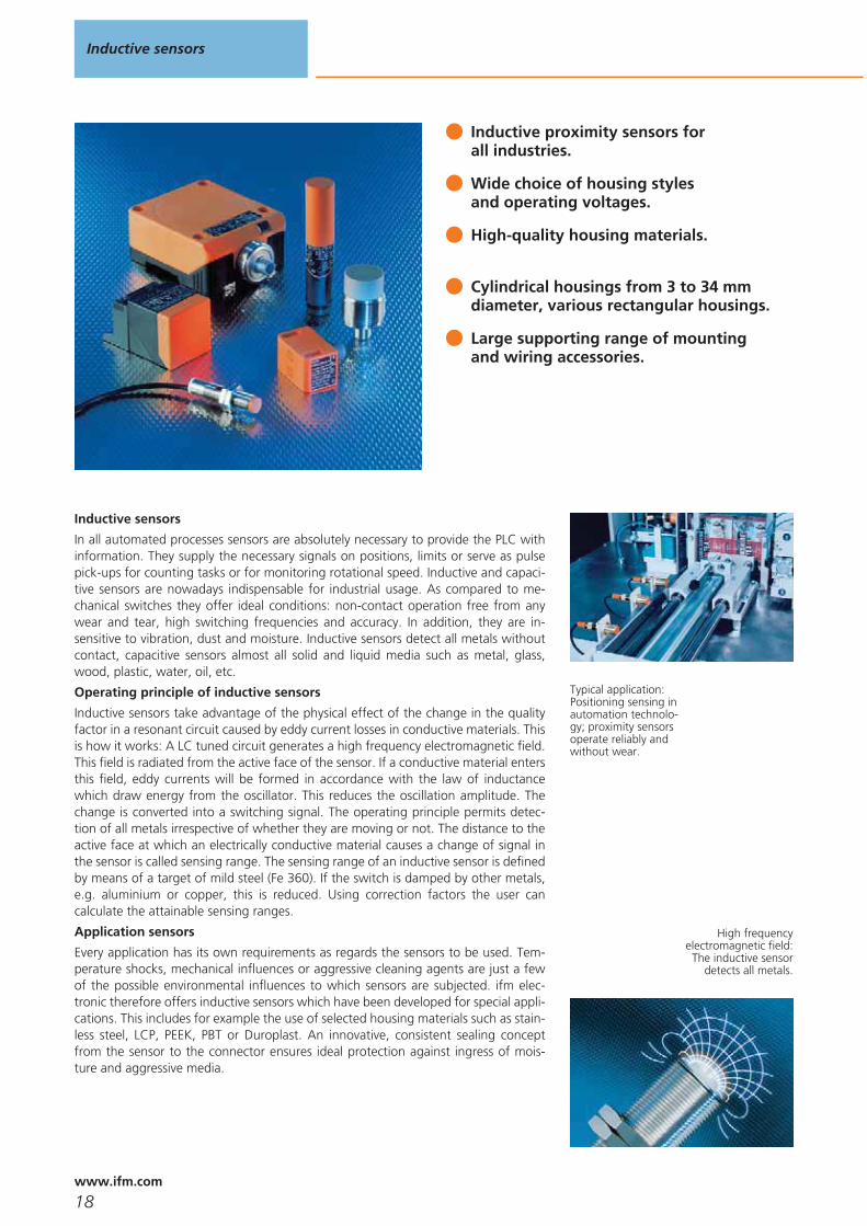
Inductive proximity sensors forall industries.
Wide choice of housing stylesand operating voltages.
High-quality housing materials.
Cylindrical housings from 3 to 34 mm diameter, various rectangular housings.
Large supporting range of mountingand wiring accessories.
Inductive sensors
In all automated processes sensors are absolutely necessary to provide the PLC withinformation. They supply the necessary signals on positions, limits or serve as pulsepick-ups for counting tasks or for monitoring rotational speed. Inductive and capaci-tive sensors are nowadays indispensable for industrial usage. As compared to me-chanical switches they offer ideal conditions: non-contact operation free from anywear and tear, high switching frequencies and accuracy. In addition, they are in-sensitive to vibration, dust and moisture. Inductive sensors detect all metals withoutcontact, capacitive sensors almost all solid and liquid media such as metal, glass,wood, plastic, water, oil, etc.
Operating principle of inductive sensors
Inductive sensors take advantage of the physical effect of the change in the qualityfactor in a resonant circuit caused by eddy current losses in conductive materials. Thisis how it works: A LC tuned circuit generates a high frequency electromagnetic field.This field is radiated from the active face of the sensor. If a conductive material entersthis field, eddy currents will be formed in accordance with the law of inductancewhich draw energy from the oscillator. This reduces the oscillation amplitude. Thechange is converted into a switching signal. The operating principle permits detec-tion of all metals irrespective of whether they are moving or not. The distance to theactive face at which an electrically conductive material causes a change of signal inthe sensor is called sensing range. The sensing range of an inductive sensor is definedby means of a target of mild steel (Fe 360). If the switch is damped by other metals,e.g. aluminium or copper, this is reduced. Using correction factors the user cancalculate the attainable sensing ranges.
Application sensors
Every application has its own requirements as regards the sensors to be used. Tem-perature shocks, mechanical influences or aggressive cleaning agents are just a fewof the possible environmental influences to which sensors are subjected. ifm elec-tronic therefore offers inductive sensors which have been developed for special appli-cations. This includes for example the use of selected housing materials such as stain-less steel, LCP, PEEK, PBT or Duroplast. An innovative, consistent sealing conceptfrom the sensor to the connector ensures ideal protection against ingress of mois-ture and aggressive media.
Typical application:Positioning sensing inautomation technolo-gy; proximity sensorsoperate reliably andwithout wear.
High frequencyelectromagnetic field:The inductive sensor
detects all metals.
Inductive sensors
18www.ifm.com
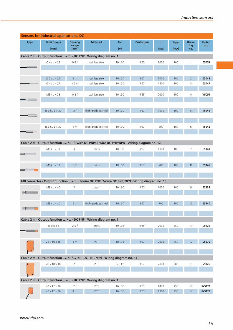
Sensors for industrial applications, DC
Type Dimensions
[mm]
Sensingrange[mm]
Material Ub
[V]
Protection f
[Hz]
Iload
[mA]
Draw-ingno.
Orderno.
Cable 2 m · Output function · DC PNP · Wiring diagram no. 1
Ø 4 / L = 23 0.8 f stainless steel 10...30 IP65 2000 100 1 IZ5051
Ø 3 / L = 27 1 nf stainless steel 10...30 IP67 5000 100 2 IZ5048
Ø 4 / L = 27 1.5 nf stainless steel 10...30 IP67 1800 100 3 IZ5047
M5 / L = 23 0.8 f stainless steel 10...30 IP65 2000 100 4 IY5051
Ø 6.5 / L = 27 2 f high-grade st. steel 10...30 IP67 1500 100 5 IT5042
Ø 6.5 / L = 27 4 nf high-grade st. steel 10...30 IP67 500 100 6 IT5043
Cable 2 m · Output function · 3-wire DC PNP; 2-wire DC PNP/NPN · Wiring diagram no. 12
M8 / L = 37 3 f brass 10...30 IP67 1000 100 7 IE5343
M8 / L = 37 5 nf brass 10...30 IP67 700 100 8 IE5345
M8 connector · Output function · 3-wire DC PNP; 2-wire DC PNP/NPN · Wiring diagram no. 13
M8 / L = 40 3 f brass 10...30 IP67 1000 100 9 IE5338
M8 / L = 40 5 nf high-grade st. steel 10...30 IP67 700 100 10 IE5340
Cable 2 m · Output function · DC PNP · Wiring diagram no. 1
40 x 8 x 8 2.5 f brass 10...36 IP65 2000 250 11 IL5020
28 x 10 x 16 4 nf PBT 10...36 IP67 2000 250 12 IS5070
Cable 2 m · Output function · DC PNP/NPN · Wiring diagram no. 14
28 x 10 x 16 2 f PBT 5...36 IP67 2000 200 13 IS5026
Cable 2 m · Output function · DC PNP · Wiring diagram no. 1
40 x 12 x 26 2 f PBT 10...36 IP67 1400 250 14 IN5121
40 x 12 x 26 4 nf PBT 10...36 IP67 1300 250 14 IN5129
Inductive sensors
19www.ifm.com
Type Dimensions
[mm]
Sensingrange[mm]
Material Ub
[V]
Protection f
[Hz]
Iload
[mA]
Draw-ingno.
Orderno.
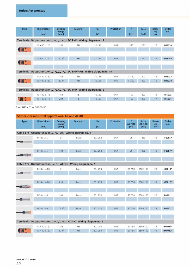
Terminals · Output function · DC PNP · Wiring diagram no. 2
40 x 40 x 120 15 f PPE 10...36 IP65 350 250 15 IM5020
40 x 40 x 120 30 nf PPE 10...36 IP65 100 250 15 IM5046
Terminals · Output function · DC PNP/NPN · Wiring diagram no. 15
40 x 40 x 120 15 f PPE 10...55 IP65 > 350 400 15 IM5037
40 x 40 x 120 20 nf PPE 10...55 IP65 > 300 400 15 IM5038
Terminals · Output function · DC PNP · Wiring diagram no. 3
40 x 40 x 118 15 f PBT 10...60 IP67 150 200 16 IV5003
40 x 40 x 118 20 f PBT 10...60 IP67 150 200 17 IV5004
f = flush / nf = non flush
Sensors for industrial applications, AC and AC/DC
Type Dimensions
[mm]
Sensingrange[mm]
Material Ub
[V]
Protection fAC / DC
[Hz]
IloadAC / DC
[mA]
Draw-ingno.
Orderno.
Cable 2 m · Output function · AC · Wiring diagram no. 4
M12 / L = 71 2 f brass 20...250 IP67 25 250 18 IF0005*
M12 / L = 71 4 nf brass 20...250 IP67 25 250 19 IF0007*
Cable 2 m · Output function · AC/DC · Wiring diagram no. 5
M18 / L = 80 5 f brass 20...250 IP67 25 / 50 350 / 100 20 IG0011*
M18 / L = 80 8 nf brass 20...250 IP67 25 / 50 350 / 100 21 IG0012*
M30 / L = 81 10 f brass 20...250 IP67 25 / 50 350 / 100 22 II0011*
M30 / L = 81 15 nf brass 20...250 IP67 25 / 50 350 / 100 23 II0012*
Terminals · Output function · AC/DC · Wiring diagram no. 6
40 x 40 x 120 15 f PPE 20...250 IP65 20 / 55 350 / 100 15 IM0011*
40 x 40 x 120 20 nf PPE 20...250 IP65 20 / 55 350 / 100 15 IM0010*
Inductive sensors
20www.ifm.com

Type Dimensions
[mm]
Sensingrange[mm]
Material Ub
[V]
Protection fAC / DC
[Hz]
IloadAC / DC
[mA]
Draw-ingno.
Orderno.
1/2“ connector · Output function · AC/DC · Wiring diagram no. 7
40 x 40 x 66 35 nf PPE 20...250 IP67 20 / 50 350 / 100 24 IM0049*
M12 connector · Output function · AC/DC · Wiring diagram no. 7
40 x 40 x 66 20 f PPE 20...250 IP67 25 / 140 350 / 100 25 IM0054*
Terminals · Output function · AC/DC · Wiring diagram no. 16
105 x 80 x 40 60 nf modified PPE 20...250 IP65 4 350 / 100 26 ID0013*
f = flush / nf = non flush
* Note for AC and AC/DC units
Miniature fuse to IEC60127-2 sheet 1, ≤ 2 A (fast acting). Recommendation: check the unit for reliable function after a shortcircuit.
Sensors with increased sensing range for industrial automation
Type Dimensions
[mm]
Sensingrange[mm]
Material Ub
[V]
Protection f
[Hz]
Iload
[mA]
Draw-ingno.
Orderno.
M12 connector · Output function · DC PNP · Wiring diagram no. 8
M12 / L = 45 4 f brass 10...36 IP67 700 100 27 IFS204
M12 / L = 50 7 nf brass 10...36 IP67 700 100 28 IFS205
M12 connector · Output function · 3-wire DC PNP; 2-wire DC PNP/NPN · Wiring diagram no. 13
M12 / L = 70 4 f brass 10...30 IP67 500 100 29 IFS208
M12 / L = 70 7 nf brass 10...30 IP67 500 100 30 IFS209
M12 connector · Output function · DC PNP · Wiring diagram no. 8
M18 / L = 46 8 f brass 10...36 IP67 400 100 31 IGS204
M18 / L = 51 12 nf brass 10...36 IP67 300 100 32 IGS205
M12 connector · Output function · 3-wire DC PNP; 2-wire DC PNP/NPN · Wiring diagram no. 13
M18 / L = 70 8 f brass 10...30 IP67 400 100 33 IGS208
Inductive sensors
21www.ifm.com
Type Dimensions
[mm]
Sensingrange[mm]
Material Ub
[V]
Protection f
[Hz]
Iload
[mA]
Draw-ingno.
Orderno.
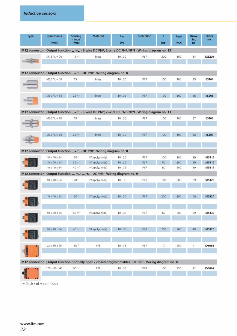
M12 connector · Output function · 3-wire DC PNP; 2-wire DC PNP/NPN · Wiring diagram no. 13
M18 / L = 70 12 nf brass 10...30 IP67 300 100 34 IGS209
M12 connector · Output function · DC PNP · Wiring diagram no. 8
M30 / L = 50 15 f brass 10...36 IP67 100 100 35 IIS204
M30 / L = 50 22 nf brass 10...36 IP67 100 100 36 IIS205
M12 connector · Output function · 3-wire DC PNP; 2-wire DC PNP/NPN · Wiring diagram no. 13
M30 / L = 70 15 f brass 10...30 IP67 100 100 37 IIS206
M30 / L = 70 22 nf brass 10...30 IP67 100 100 38 IIS207
M12 connector · Output function · DC PNP · Wiring diagram no. 8
40 x 40 x 54 20 f PA (polyamide) 10...36 IP67 100 200 39 IM5115
40 x 40 x 54 35 nf PA (polyamide) 10...36 IP67 80 200 39 IM5116
40 x 40 x 54 40 nf PA (polyamide) 10...36 IP67 60 200 39 IM5117
M12 connector · Output function · DC PNP · Wiring diagram no. 9
40 x 40 x 54 20 f PA (polyamide) 10...36 IP67 100 200 39 IM5123
40 x 40 x 54 20 f PA (polyamide) 10...36 IP67 200 200 40 IM5124
40 x 40 x 54 40 nf PA (polyamide) 10...36 IP67 60 200 39 IM5136
40 x 40 x 54 40 nf PA (polyamide) 10...36 IP67 200 200 40 IM5126
92 x 80 x 40 50 f PPE 10...36 IP67 70 250 41 ID5058
M12 connector · Output function normally open / closed programmable) · DC PNP · Wiring diagram no. 8
105 x 80 x 40 60 nf PPE 10...36 IP67 100 250 42 ID5046
f = flush / nf = non flush
Inductive sensors
22www.ifm.com
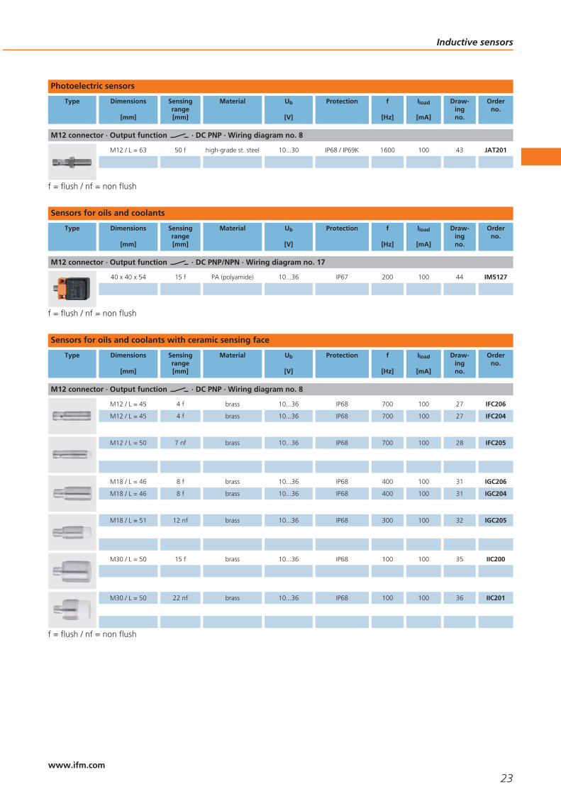
Photoelectric sensors
Type Dimensions
[mm]
Sensingrange[mm]
Material Ub
[V]
Protection f
[Hz]
Iload
[mA]
Draw-ingno.
Orderno.
M12 connector · Output function · DC PNP · Wiring diagram no. 8
M12 / L = 63 50 f high-grade st. steel 10...30 IP68 / IP69K 1600 100 43 JAT201
f = flush / nf = non flush
Sensors for oils and coolants
Type Dimensions
[mm]
Sensingrange[mm]
Material Ub
[V]
Protection f
[Hz]
Iload
[mA]
Draw-ingno.
Orderno.
M12 connector · Output function · DC PNP/NPN · Wiring diagram no. 17
40 x 40 x 54 15 f PA (polyamide) 10...36 IP67 200 100 44 IM5127
f = flush / nf = non flush
Sensors for oils and coolants with ceramic sensing face
Type Dimensions
[mm]
Sensingrange[mm]
Material Ub
[V]
Protection f
[Hz]
Iload
[mA]
Draw-ingno.
Orderno.
M12 connector · Output function · DC PNP · Wiring diagram no. 8
M12 / L = 45 4 f brass 10...36 IP68 700 100 27 IFC206
M12 / L = 45 4 f brass 10...36 IP68 700 100 27 IFC204
M12 / L = 50 7 nf brass 10...36 IP68 700 100 28 IFC205
M18 / L = 46 8 f brass 10...36 IP68 400 100 31 IGC206
M18 / L = 46 8 f brass 10...36 IP68 400 100 31 IGC204
M18 / L = 51 12 nf brass 10...36 IP68 300 100 32 IGC205
M30 / L = 50 15 f brass 10...36 IP68 100 100 35 IIC200
M30 / L = 50 22 nf brass 10...36 IP68 100 100 36 IIC201
f = flush / nf = non flush
Inductive sensors
23www.ifm.com

Sensors for mobile applications
Type Dimensions
[mm]
Sensingrange[mm]
Material Ub
[V]
Protection f
[Hz]
Iload
[mA]
Draw-ingno.
Orderno.
M12 connector · Output function · DC PNP · Wiring diagram no. 8
M12 / L = 70 4 f high-grade st. steel 10...60 IP67 / IP69K 400 200 45 IFM205
M12 / L = 70 7 nf stainless steel 10...60 IP67 / IP69K 300 200 46 IFM206
M18 / L = 70 8 f stainless steel 10...60 IP67 / IP69K 200 200 47 IGM204
M18 / L = 70 12 nf stainless steel 10...60 IP67 / IP69K 200 200 48 IGM205
M30 / L = 70 12 f stainless steel 10...60 IP67 / IP69K 100 200 37 IIM208
M30 / L = 70 22 nf stainless steel 10...60 IP67 / IP69K 100 200 38 IIM209
f = flush / nf = non flush
Full-metal sensors with non-stick coating against weld spatter
Type Dimensions
[mm]
Sensingrange[mm]
Material Ub
[V]
Protection f
[Hz]
Iload
[mA]
Draw-ingno.
Orderno.
M12 connector · Output function · DC PNP · Wiring diagram no. 8
M8 / L = 60 2 f stainless steel 10...36 IP67 / IP68 100 100 49 IER200
M12 / L = 60 4 f high-grade st. steel 10...36 IP67 2 100 50 IFR200
M18 / L = 70 6 f high-grade st. steel 10...36 IP67 2 100 51 IGR200
M30 / L = 70 12 f high-grade st. steel 10...36 IP67 2 100 52 IIR200
f = flush / nf = non flush
Inductive sensors
24www.ifm.com

Electromagnetic field immune sensors with correction factor K = 1
Type Dimensions
[mm]
Sensingrange[mm]
Material Ub
[V]
Protection f
[Hz]
Iload
[mA]
Draw-ingno.
Orderno.
M12 connector · Output function · DC PNP · Wiring diagram no. 9
40 x 40 x 54 20 f PA (polyamide) 10...36 IP67 200 200 40 IM5124
40 x 40 x 54 40 nf PA (polyamide) 10...36 IP67 200 200 40 IM5126
f = flush / nf = non flush
Electromagnetic field immune sensors
Type Dimensions
[mm]
Sensingrange[mm]
Material Ub
[V]
Protection f
[Hz]
Iload
[mA]
Draw-ingno.
Orderno.
M12 connector · Output function · DC PNP · Wiring diagram no. 8
40 x 40 x 118 15 f modified PPE 10...60 IP67 50 200 53 IV5025
M12 connector · Output function · DC PNP · Wiring diagram no. 9
92 x 80 x 40 50 f PPE 10...36 IP67 70 250 41 ID5059
f = flush / nf = non flush
Full-metal sensors for hygienic and wet areas
Type Dimensions
[mm]
Sensingrange[mm]
Material Ub
[V]
Protection f
[Hz]
Iload
[mA]
Draw-ingno.
Orderno.
M12 connector · Output function · DC PNP · Wiring diagram no. 8
M12 / L = 60 3 f high-grade st. steel 10...36 IP68 / IP69K 100 100 50 IFT240
M18 / L = 70 5 f high-grade st. steel 10...36 IP68 / IP69K 100 100 51 IGT247
M30 / L = 70 10 f high-grade st. steel 10...36 IP68 / IP69K 50 100 52 IIT228
f = flush / nf = non flush
Sensors for hygienic and wet areas with increased sensing range
Type Dimensions
[mm]
Sensingrange[mm]
Material Ub
[V]
Protection f
[Hz]
Iload
[mA]
Draw-ingno.
Orderno.
M12 connector · Output function · DC PNP · Wiring diagram no. 8
M12 / L = 45 4 f high-grade st. steel 10...36 IP68 / IP69K 800 100 27 IFT203
M12 / L = 50 7 nf high-grade st. steel 10...36 IP68 / IP69K 800 100 54 IFT200
Inductive sensors
25www.ifm.com

Type Dimensions
[mm]
Sensingrange[mm]
Material Ub
[V]
Protection f
[Hz]
Iload
[mA]
Draw-ingno.
Orderno.
M12 connector · Output function · 3-wire DC PNP; 2-wire DC PNP/NPN · Wiring diagram no. 13
M12 / L = 70 4 f high-grade st. steel 10...36 IP68 / IP69K 500 100 29 IFT205
M12 / L = 70 7 nf high-grade st. steel 10...30 IP68 / IP69K 700 100 46 IFT202
Cable 6 m · Output function · DC PNP · Wiring diagram no. 1
M12 / L = 50 4 f high-grade st. steel 10...36 IP68 / IP69K 800 100 55 IFT206
M12 / L = 61 7 nf high-grade st. steel 10...36 IP68 / IP69K 800 100 56 IFT208
M12 connector · Output function · DC PNP · Wiring diagram no. 8
M18 / L = 46 8 f high-grade st. steel 10...36 IP68 / IP69K 600 100 31 IGT203
M18 / L = 51 12 nf high-grade st. steel 10...36 IP68 / IP69K 300 100 57 IGT200
M12 connector · Output function · 3-wire DC PNP; 2-wire DC PNP/NPN · Wiring diagram no. 13
M18 / L = 70 8 f high-grade st. steel 10...30 IP68 / IP69K 400 100 47 IGT205
M18 / L = 70 12 nf high-grade st. steel 10...30 IP68 / IP69K 300 100 58 IGT202
Cable 6 m · Output function · DC PNP · Wiring diagram no. 1
M18 / L = 57 8 f high-grade st. steel 10...36 IP68 / IP69K 600 100 59 IGT206
M18 / L = 62 12 nf high-grade st. steel 10...36 IP68 / IP69K 300 100 60 IGT208
M12 connector · Output function · DC PNP · Wiring diagram no. 8
M30 / L = 50 14 f high-grade st. steel 10...36 IP68 / IP69K 50 100 35 IIT205
M30 / L = 50 22 nf high-grade st. steel 10...36 IP68 / IP69K 100 100 61 IIT200
M12 connector · Output function · 3-wire DC PNP; 2-wire DC PNP/NPN · Wiring diagram no. 13
M30 / L = 70 14 f high-grade st. steel 10...36 IP68 / IP69K 50 100 37 IIT204
Inductive sensors
26www.ifm.com

Type Dimensions
[mm]
Sensingrange[mm]
Material Ub
[V]
Protection f
[Hz]
Iload
[mA]
Draw-ingno.
Orderno.
M12 connector · Output function · 3-wire DC PNP; 2-wire DC PNP/NPN · Wiring diagram no. 13
M30 / L = 70 22 nf high-grade st. steel 10...36 IP68 / IP69K 100 100 38 IIT202
1/2“ connector · Output function · AC/DC · Wiring diagram no. 10
M30 / L = 70 22 nf high-grade st. steel 20...140 IP68 / IP69K 25 / 100 200 62 IIT002
Cable 6 m · Output function · DC PNP · Wiring diagram no. 1
M30 / L = 59 22 nf high-grade st. steel 10...36 IP68 / IP69K 100 100 63 IIT207
M30 / L = 59 14 f high-grade st. steel 10...36 IP68 / IP69K 100 100 64 IIT209
f = flush / nf = non flush
Sensors with ATEX / IECex approval 1D / 1G / 2G
Type Dimensions
[mm]
Sensingrange[mm]
Material Unom.at 1 KΩ
[V]
Ub
[V]
Internalcapacit.
[nF]
Internalinductance
[μH]
f
[Hz]
Draw-ingno.
Orderno.
M12 connector · Output function · Connection to certified intrinsically safe circuits with the max. values U = 15 V / I = 50 mA / P = 120 mW · Wiring diagram no. 11
M12 / L = 45 4 f brass 8.2 DC 7.5...30 210 115 700 27 NF501A
M12 / L = 50 7 nf brass 8.2 DC 7.5...30 210 145 700 28 NF500A
M18 / L = 46 8 f brass 8.2 DC 7.5...30 200 190 400 31 NG501A
M18 / L = 51 12 nf brass 8.2 DC 7.5...30 200 85 300 32 NG500A
M30 / L = 50 15 f brass 8.2 DC 7.5...30 230 210 100 35 NI501A
M30 / L = 50 22 nf brass 8.2 DC 7.5...30 250 120 100 36 NI500A
f = flush / nf = non flush
Inductive sensors
27www.ifm.com

Switching amplifiers with ATEX / IECex approval
Type Ub
[V]
Power / currentconsumption[VA] / [mA]
f
[Hz]
Ta
[°C]
Output Protection Draw-ingno.
Orderno.
24 / < 50 5000 -20...602 transistor outputs PNP (100 mA, short-
circuit protection)IP20 65 N0531A
24 / < 50 5000 -20...602 outputs (optocoupler, bipolar, 100 mA,
short-circuit protection)IP20 65 N0532A
24 / < 50 5000 -20...602 transistor outputs PNP (100 mA, short-
circuit protection)IP20 65 N0534A
Sensors with ATEX approval 3D
Type Dimensions
[mm]
Sensingrange[mm]
Material Ub
[V]
Protection f
[Hz]
Iload
[mA]
Draw-ingno.
Orderno.
M12 connector · Output function · DC PNP · Wiring diagram no. 8
M12 / L = 60 3 f high-grade st. steel 10...36 IP67 100 100 50 IF502A
M18 / L = 70 5 f high-grade st. steel 10...36 IP67 100 100 51 IG509A
M30 / L = 70 10 f high-grade st. steel 10...36 IP67 50 100 66 II501A
M12 connector · Output function · DC PNP · Wiring diagram no. 9
40 x 40 x 54 40 nf PA (polyamide) 10...30 IP5x 100 200 39 IM503A
40 x 40 x 54 20 f PA (polyamide) 10...30 IP5x 100 200 39 IM504A
f = flush / nf = non flush
Accessories
Type Description Orderno.
Angle bracket · for type M8 · Housing materials: stainless steel E10734
Angle bracket · for type M12 · Housing materials: stainless steel E10735
Angle bracket · for type M18 · Housing materials: stainless steel E10736
Angle bracket · for type M30 · Housing materials: stainless steel E10737
Mounting clamp · Ø 8 mm · with end stop · for type M8 · Housing materials: PC E11521
Inductive sensors
28www.ifm.com

Type Description Orderno.
Mounting clamp · Ø 34 mm · Housing materials: PBT E10017
Mounting clip · Ø 12 mm · for smooth body switches - Ø 12 mm · Form V · Housing materials: V4A E11530
Mounting clip · Ø 18 mm · for smooth body switches - Ø 18 mm · Form V · Housing materials: V4A E11531
Mounting clip · Form O · for type M12 · Housing materials: stainless steel E11533
Mounting clip · Form O · for type M18 · Housing materials: stainless steel E11534
Mounting clamp · Ø 12 mm · with end stop · for type M12 · Housing materials: PC E11047
Mounting clamp · Ø 18 mm · with end stop · for type M18 · Housing materials: PC E11048
Mounting set · Ø 18.5 mm · Clamp mounting · free-standing M10 · for type OG, IG, KG · Housing materials: clamp: diecast zinc /fixture: steel
E20718
Mounting set · Ø 12.2 mm · Clamp mounting · free-standing M8 · for type OF, IF · Housing materials: fixture: stainless steel 316Ti /1.4571 / clamp: diecast zinc
E20860
Mounting set · Ø 12.2 mm · Clamp mounting · free-standing M8 · for type OF, IF · Housing materials: fixture: stainless steel 316Ti /1.4571 / clamp: stainless steel
E20861
Mounting set · Ø 18.5 mm · Clamp mounting · free-standing M10 · for type OG, IG, KG · Housing materials: fixture: stainless steel316Ti / 1.4571 / clamp: stainless steel
E20870
Mounting set · Ø 30.2 mm · Clamp mounting · free-standing M12 · for type OI, II, KI · Housing materials: fixture: stainless steel316Ti / 1.4571 / clamp: diecast zinc
E20873
Mounting set · Ø 30.2 mm · Clamp mounting · free-standing M12 · for type OI, II, KI · Housing materials: fixture: stainless steel316Ti / 1.4571 / clamp: stainless steel
E20874
Plastic nut for flow plate · M18 x 1 · Housing materials: POM E19503
Inductive sensors
29www.ifm.com

Wiring diagrams
1
BN
BK
BU
L+
L
2
/ L+
L
13
/2 4
3
L
L+4
2
1
32:4:
4
BN
BU
L1
N
5
BN
BU
L+L1
LN
6
/1 3
/2 4
L1L+
LN
7
1
3
2
L1L+
LN
8
L+
L
1
4
3
9
4
L
L+1
2
32:4:
10
3
2
L1
N
L+
L
11
L+
L2
1
1
1: connection to NAMUR-amplifier
12
L+
L
BN
BK
BU
L+
L
BN
BK
13
L+
L
1
4
L+
L
1
4
3
14
WH
BK
L+
L L
BK
WH
L+
15
L+
L
/1 3
/2 4
L+
L/1 3
/2 4
16
2
4
3
1
5
AC;DC NPN
L+N
LL1
2
4
3
1
5
AC;DC NPN
L+N
LL1
2
4
3
1
5
DC PNP
L+
L
2
4
3
1
5
DC PNP
L+
L
17
L+
L1
4L+
L
1
4
Inductive sensors
30www.ifm.com

Scale drawings - CAD download: www.ifm.com
1
LED
2316 4
2
LED
2717 3
3
LED
2715,4 4
4
16
LED
1823
M5x
0,5
2,7
8
5
LED
3,5 27 6,5
6
LED 8
3,5
27
6,5
7
35
LED
M8x
1
413
2
8
27
LED
M8x
1
413
82
9
4
13
28,5
40
M8x
1
LED 4 x 90°
M8x
1
32,5
10
23
40
M8x
1
LED 4 x 90°
4
13
M8x
1
832,5
11
20 105M3
8
LED
40
520
IL 5003
4
IL 50021
1: sensing face
12
10,2
27,8
5,6
1622
,2
2,75
3,1
3,5
2,83,1
LED10,4
8
13
10,2
27,8
LED
5,6
165,1
22,2
2,75
3,1
3,5
2,83,1
LED
10,4
Inductive sensors
31www.ifm.com
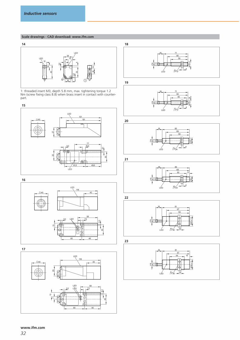
Scale drawings - CAD download: www.ifm.com
14
406
12LED
4
2613
32
3,2 45
LED
3,2
18
1610
1
1: threaded insert M3, depth 5.8 mm, max. tightening torque 1.2Nm (screw fixing class 8.8) when brass insert in contact with counter-part.
15
40
10,4
45,6
LED
32
5,3
30
61,5
77
5,1
121101
LED
27
16
40
13
7,35,3
46
30
60
LED58
5,3
40118
LED
17
7,35,3
46
LED
30
60
137
LED58
5,3
40118
LED
29
40
18
9
18 7160
50
M12
x1
LED 174
19
9
18 716046
M12
x1
LED 174
4
20
24LED
801869
58
M18
x1
4
9
21
24LED
80186950
M18
x1
4
9
8
22
36
8167
59
5
M30
x1,5
9
18
LED
23
8167
5
1544
36
M30
x1,5
9
18
LED
Inductive sensors
32www.ifm.com
Scale drawings - CAD download: www.ifm.com
24
40
LED
4661
30 20
5,4
105,
4 6
8,5
33
1/2"
20U
NF
2ALS
100
4066
17
34
25
40
M12
x1
4066
17
34
LED
4661
30 20
5,4
105,
4 6
16
33
26
105
80
40
7,565
65
5,59,3 40
12
2718
LEDpot.
16
27
453432
M12
x1
174
M12
x1
LED 4 x 90°
28
32
M12
x1
174
5
M12
x1
3950
LED 4 x 90°
29
LED 4 x 90°
5970
50
M12
x1
174
M12
x1
30
45
M12
x1
174
5
M12
x1
5970
LED 4 x 90°
31
M18
x1
M12
x1
3033
4635
424LED 4 x 90°
32
M18
x1
M12
x1
2538
5140
424
10
LED 4 x 90°
33
M18
x1
M12
x1
4956,5
7059
424LED 4 x 90°
Inductive sensors
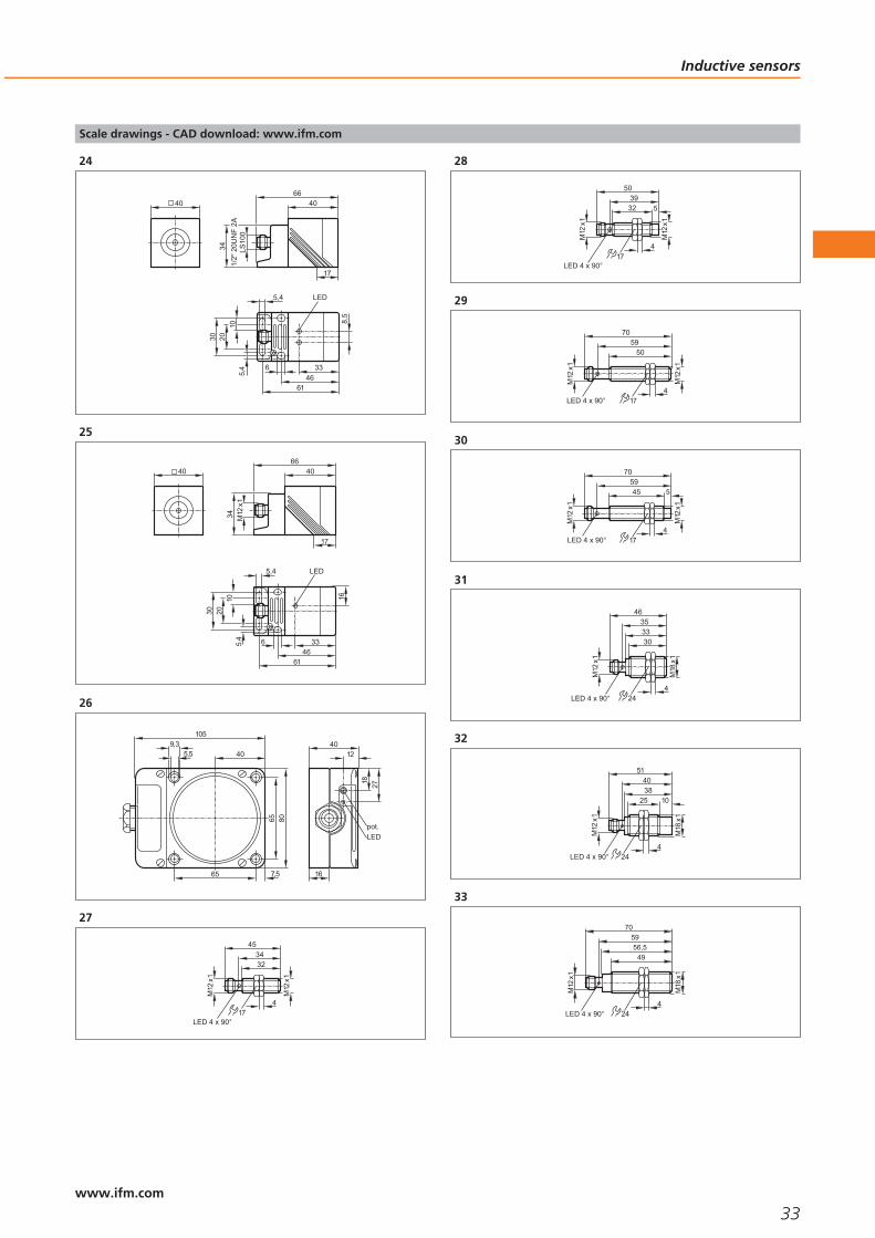
33www.ifm.com
Scale drawings - CAD download: www.ifm.com
34
M18
x1
M12
x1
4058
70
LED 4 x 90°
60
10
424
35
39
33
M30
x1,5
37
50
M12
x1
LED 4 x 90° 5 36
36
39
19
M30
x1,5
37
50
M12
x1
LED 4 x 90° 5
15
36
37
59
53
M30
x1,5
57
70
M12
x1
LED 4 x 90° 536
38
LED 4 x 90°
59
38
M30
x1,5
5
57
70
36
M12
x1
15
39
40
66
40
54
M12
x130
30 2
2
1
46
46
5,5
5,5
29,5
1: LED yellow, 2: LED green
40
40
66
40
54
M12
x130
30 2
5,5
5,5
1
2
46
46
29,5
1: LED yellow, 2: LED green
41
92
80
40
7,565
65
5,59,3
M12
x1
112
40
LED171
20
1: mounting on DIN rail
Inductive sensors
34www.ifm.com

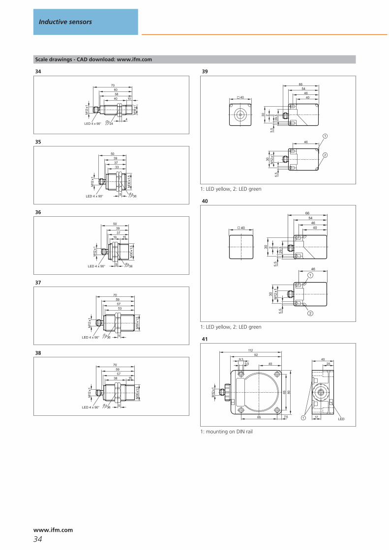
Scale drawings - CAD download: www.ifm.com
42
105
80
40
7,565
65
5,59,3
M12
x1
123
4012
2718
LEDpot.
16
43
M12
x1
174
M12
x1
5263
LED 4 x 90°
43
44
40
66
40
54
M12
x130
30 2
46
46
5,5
5,5
LED
29,5
45
5950
M12
x1
174
M12
x1
LED
70
46
45
M12
x1
174
5
M12
x1
5970
LED
47
M18
x1
M12
x1
5057
7059
424LED 4 x 90°
48
M18
x1
M12
x1
4057
70
LED 4 x 90°
59
10
424
49
M8x
1
4
13M
12x1
6049
33
LED 4 x 90°
50
4940
M12
x1
174
M12
x1
LED 4 x 90°
60
51
5957
50
M18
x1
4
M12
x1
70
24LED 4 x 90°
52
58
50
M30
x1,5
5
57
70
36
M12
x1
LED 4 x 90°
Inductive sensors
35www.ifm.com

Scale drawings - CAD download: www.ifm.com
53
40118
LEDM
12x1
139
13
7,35,3
4630
60
LED58
5,3
40
54
32
M12
x1
174
5
M12
x1
3950
LED 4 x 90°
55
5037
29
M12
x1
174
LED
56
5
614428
M12
x1
LED 4 x 90° 174
5
57
M18
x1
M12
x1
2538
5140
424
10
LED 4 x 90°
58
M18
x1
M12
x1
3956
70
LED 4 x 90°
59
10
424
59
5739,5
2933
LED4 x 90°
M18
x1
424
5
60
6244,5
24
LED4 x 90°
38
M18
x1
424
10
61
39
18
M30
x1,5
37
50
M12
x1LED 4 x 90° 5
15
36
62
38
M30
x1,5
57
70
LED4 x 90°
536
15
59
1/2"
-20U
NF-
2A
63
16
M30
x1,5
1535
5
42
LED 4 x 90°
59
5 36
64
31
M30
x1,5
35
5
42
LED 4 x 90°
59
365
Inductive sensors
36www.ifm.com
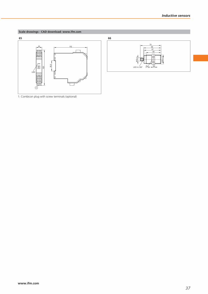
Scale drawings - CAD download: www.ifm.com
65
112
35,5
20
120
LED
1
1: Combicon plug with screw terminals (optional)
66
58
50
M30
x1,5
5
57
70
36
M12
x1
LED 4 x 90°
Inductive sensors
37www.ifm.com

38

Capacitive sensors
Selection chart Page
Sensors for industrial applications, DC 41
Sensors for industrial applications, AC and AC/DC 41 - 42
Sensors for the detection of conductive media through a wall 42
Sensors for the detection of granulates 42
Sensors for the detection of granulates 43
Sensors with ATEX approval 43
Switching amplifiers with ATEX approval 43
Accessories 43 - 45
Wiring diagrams 45
Scale drawings - CAD download: www.ifm.com 46
39www.ifm.comwww.ifm.com

Capactive sensors for detection ofnon-metalic objects.
Sensing range adjustable by means of a potentiometer.
Plastic or metal housing for different applications.
Housing styles from M12 cylindricalto 105 x 80 mm block.
Assortment of tank and sight glassmounting acccessories.
Capacitive sensors
Capacitive sensors are used for the non-contact detection of any objects. In contrastto inductive sensors, which only detect metallic objects, capacitive sensors can alsodetect non-metallic materials. Typical applications are in the wood, paper, glass,plastic, food and chemical industries. In a packaging system, capacitive sensors moni-tor that the contents of a cardboard box is complete, for example, or check the pres-ence of non-metallic caps. Another application is to monitor the conveying of sheetsof glass on a roller conveyor.
Operating principle
The capacitance between the active electrode of the sensor and the electrical earthpotential is evaluated. An approaching object influences the electrical alternatingfield between these two “capacitor plates” and, consequently, the capacitance. Thisapplies to metallic and non-metallic objects. By means of the potentiometer or thepushbutton the user can set the sensitivity.
Increased noise immunity
When detecting objects, very small changes in capacitance must be evaluated andconverted into switching signals. This makes high requirements for the electronics.The sensors must be designed so that they are insensitive to fluctuations of theparasitic basic capacitances, as these can amount to a multiple of the change incapacitance to be measured. Moreover, the sensors must be insensitive to electro-magnetic interference which typically occur in the application area.
ifm electronic has developed future-oriented solutions to meet the high sensorrequirements. A patented circuit concept efficiently prevents the mentioned pro-blems and ensures reliable functioning for all relevant noise parameters.
Not only metal: Capacitive sensorsdetect almost allmaterials, herefor example a login a saw mill.
Capacitive sensors
40www.ifm.com

Sensors for industrial applications, DC
Type Dimensions
[mm]
Sensingrange[mm]
Material Ub
[V]
Protection f
[Hz]
Iload
[mA]
Draw-ingno.
Orderno.
Cable 2 m · Output function · DC PNP · Wiring diagram no. 1
M30 / L = 81 15 nf PBT 10...36 IP65 40 250 1 KI5002
Cable 2 m · Output function · DC PNP · Wiring diagram no. 2
M30 / L = 81 15 nf PBT 10...36 IP65 40 250 1 KI5001
M12 connector · Output function · DC PNP · Wiring diagram no. 3
M30 / L = 90 8 f high-grade st. steel 10...36 IP65 / IP67 10 100 2 KI5085
M30 / L = 90 15 nf high-grade st. steel 10...36 IP65 / IP67 10 100 3 KI5087
M12 connector · Output function · DC PNP/NPN · Wiring diagram no. 9
M30 / L = 90 8 f high-grade st. steel 10...36 IP65 / IP67 10 100 2 KI5084
Terminals · Output function · DC PNP · Wiring diagram no. 10
105 x 80 x 40 60 nf modified PPO 10...36 IP65 10 250 4 KD5018
f = flush / nf = non flush
Sensors for industrial applications, AC and AC/DC
Type Dimensions
[mm]
Sensingrange[mm]
Material Ub
[V]
Protection fAC / DC
[Hz]
IloadAC / DC
[mA]
Draw-ingno.
Orderno.
Cable 2 m · Output function · AC/DC · Wiring diagram no. 4
M18 / L = 84 8 nf PBT 20...250 IP67 25 / 50 350 / 100 5 KG0009*
Cable 2 m · Output function · AC/DC · Wiring diagram no. 5
M18 / L = 84 8 nf PBT 20...250 IP67 25 / 50 350 / 100 5 KG0010*
Cable 2 m · Output function · AC/DC · Wiring diagram no. 4
M30 / L = 81 15 nf PBT 20...250 IP65 25 / 40 250 1 KI0016*
Capacitive sensors
41www.ifm.com

Type Dimensions
[mm]
Sensingrange[mm]
Material Ub
[V]
Protection fAC / DC
[Hz]
IloadAC / DC
[mA]
Draw-ingno.
Orderno.
Cable 2 m · Output function · AC/DC · Wiring diagram no. 5
M30 / L = 81 15 nf PBT 20...250 IP65 25 / 40 250 1 KI0020*
Terminals · Output function · AC/DC · Wiring diagram no. 11
105 x 80 x 40 60 nf modified PPO 20...250 IP65 10 250 4 KD0009*
f = flush / nf = non flush
* Note for AC and AC/DC units
Miniature fuse to IEC60127-2 sheet 1, ≤ 2 A (fast acting). Recommendation: check the unit for reliable function after a shortcircuit.
Sensors for the detection of conductive media through a wall
Type Dimensions
[mm]
Sensingrange[mm]
Material Ub
[V]
Protection f
[Hz]
Iload
[mA]
Draw-ingno.
Orderno.
Cable 2 m · Output function · 1x open collector with automatic load detection (DC PNP or DC NPN) · Wiring diagramno. 12
20 x 14 x 48 12 nf PBT 10...36 IP65 / IP67 10 100 6 KQ6001
Cable with connector 0.04 m · Output function · 1x open collector with automatic load detection (DC PNP or DC NPN)· Wiring diagram no. 9
20 x 14 x 48 12 nf PBT 10...36 IP65 / IP67 10 100 6 KQ6003
Cable with connector 0.1 m · Output function · 1x open collector DC PNP · Wiring diagram no. 3
20 x 14 x 48 12 nf PBT 10...36 IP65 / IP67 10 100 6 KQ6005
f = flush / nf = non flush
Sensors for the detection of granulates
Type Dimensions
[mm]
Sensingrange[mm]
Material Ub
[V]
Protection f
[Hz]
Iload
[mA]
Draw-ingno.
Orderno.
M12 connector · Output function · DC PNP/NPN · Wiring diagram no. 9
M18 / L = 87 12 nf PBT 10...36 IP65 / IP67 10 200 7 KG5065
M30 / L = 90 20 nf PBT 10...36 IP65 / IP67 10 200 8 KI5082
f = flush / nf = non flush
Capacitive sensors
42www.ifm.com

Sensors for the detection of granulates
Type Dimensions
[mm]
Sensingrange[mm]
Material Ub
[V]
Protection f
[Hz]
Iload
[mA]
Draw-ingno.
Orderno.
1/2“ UNF-Connector · Output function · AC/DC · Wiring diagram no. 6
M30 20 nf PBT 20...250 IP65 / IP67 10 150 9 KI0054*
f = flush / nf = non flush
* Note for AC and AC/DC units
Miniature fuse to IEC60127-2 sheet 1, ≤ 2 A (fast acting). Recommendation: check the unit for reliable function after a shortcircuit.
Sensors with ATEX approval
Type Dimensions
[mm]
Sensingrange[mm]
Material Unom.at 1 KΩ
[V]
Ub
[V]
Internalcapacit.
[nF]
Internalinductance
[μH]
f
[Hz]
Draw-ingno.
Orderno.
Cable 2 m · Output function · Connection to certified intrinsically safe circuits with the max. values U = 15 V / I = 50 mA / P =120 mW · Wiring diagram no. 7
M30 / L = 81 15 nf PBT 8.2 DC 7.5...15 375 1 40 1 KI5030
Cable 2 m · Output function · Connection to certified intrinsically safe circuits with the max. values U = 15 V / I = 50 mA / P =120 mW · Wiring diagram no. 8
M34 / L = 92 15 nf brass 8.2 DC 7.5...15 375 1 40 10 KX5001
f = flush / nf = non flush
Switching amplifiers with ATEX approval
Type Ub
[V]
Power / currentconsumption[VA] / [mA]
f
[Hz]
Ta
[°C]
Output Protection Draw-ingno.
Orderno.
24 / < 50 5000 -20...602 transistor outputs PNP (100 mA, short-
circuit protection)IP20 11 N0531A
24 / < 50 5000 -20...602 outputs (optocoupler, bipolar, 100 mA,
short-circuit protection)IP20 11 N0532A
24 / < 50 5000 -20...602 transistor outputs PNP (100 mA, short-
circuit protection)IP20 11 N0534A
Accessories
Type Description Orderno.
Mounting clamp · Ø 34 mm · Housing materials: PBT E10017
Angle bracket · for type M12 · Housing materials: stainless steel E10735
Capacitive sensors
43www.ifm.com

Type Description Orderno.
Angle bracket · for type M18 · Housing materials: stainless steel E10736
Angle bracket · for type M30 · Housing materials: stainless steel E10737
Locknut · G 1¼ · for mounting adapter · Housing materials: PVDF E11030
Locknut · G 1½ · for mounting adapter · Housing materials: POM E11031
Locknut · G 1½ · for mounting adapter · Housing materials: PVDF E11032
Mounting adapter · M30 x 1.5 - G 1½ · Housing materials: POM / EPDM E11033
Mounting adapter · M30 x 1.5 - G 1½ · Housing materials: PVDF / EPDM E11034
Mounting adapter · M30 x 1.5 - G 1¼ · Housing materials: PVDF / EPDM E11036
Protective cover · G 1¼ · for mounting adapter · Housing materials: PES black transparent E11078
Mounting set · Ø 18.5 mm · Clamp mounting · free-standing M10 · for type OG, IG, KG · Housing materials: clamp: diecast zinc /fixture: steel
E20718
Mounting set · Ø 18.5 mm · Clamp mounting · free-standing M10 · for type OG, IG, KG · Housing materials: fixture: stainless steel316Ti / 1.4571 / clamp: stainless steel
E20870
Mounting set · Ø 30.2 mm · Clamp mounting · free-standing M12 · for type OI, II, KI · Housing materials: fixture: stainless steel316Ti / 1.4571 / clamp: diecast zinc
E20873
Mounting set · Ø 30.2 mm · Clamp mounting · free-standing M12 · for type OI, II, KI · Housing materials: fixture: stainless steel316Ti / 1.4571 / clamp: stainless steel
E20874
Mounting adapter · M18 x 1 - G ¾ · Housing materials: PVDF E43901
Capacitive sensors
44www.ifm.com

Type Description Orderno.
Locknut · G ¾ · for mounting adapter · Housing materials: PVDF E43903
Mounting adapter for free-standing mounting · for type KQ · Housing materials: adapter: PBT / inserts: brass / screw: steel galvanised· Pack quantity: 1
E12153
Wiring diagrams
1
BN
BK
BU
L+
L
2
BN
BK
BU
L+
L
3
L+
L
1
4
3
4
BN
BU
L+L1
LN
5
BN
BU
L+L1
LN
6
2
3
L1
N
L+
L
7
+BN
BU
8
BN
GN/YE
BU+
9
L+
L
1
4
3
L+
L
1
4
3
10
2
4
3
1
5
L+
L
2
4
3
1
5
L+
L
11
2
4
3
1
5
AC;DC NPN
L+N
LL1
2
4
3
1
5
AC;DC NPN
L+N
LL1
2
4
3
1
5
DC PNP
L+
L
2
4
3
1
5
DC PNP
L+
L
12
L
L+BN
BK
BU L
L+BN
BK
BU
Capacitive sensors
45www.ifm.com

Scale drawings - CAD download: www.ifm.com
1
36
8159
5
M30
x1,5
9
18pot.LED
2
60
M30
x1,5
7790
LED (4 x 90°) 5
M12
x 1
361
1: Programming buttons
3
60
M30
x1,5
7790
LED (4 x 90°) 5
M12
x 1
361
15
1: Programming buttons
4
105
80
40
7,565
65
5,59,3 40
12
2718
LEDpot.
16
5
24
58
4
84
M18
x1
pot.LED LEDpot.
6
3,2
48
3343,7
2
5,5 3
13,4
14
20
121
1: Programming buttons, 2: sensing face
7
24
7756
M18
x1
4
M12
x1
87
1 2
1: LED ring, 2: Programming buttons
8
61
M30
x1,5
8090
5
M12
x 1
3621
1: LED ring, 2: Programming buttons
9
6180
90
5
M30
3621
1/2"
UN
F
1: LED ring, 2: Programming buttons
10
822040
M34
x1,5
10
541
LEDpot.
Capacitive sensors
46www.ifm.com

Scale drawings - CAD download: www.ifm.com
11
112
35,5
20
120
LED
1
1: Combicon plug with screw terminals (optional)
Capacitive sensors
47www.ifm.com

48

Cylinder sensors
Selection chart Page
T-slot sensors for industrial applications 51
T-slot reed sensors for industrial applications 51
T-slot sensors for hygienic and wet ares 52
Sensors for short-stroke cylinders 52
Sensors for short-stroke cylinders for hygienic and wet areas 52
Non flush C-slot sensors for industrial applications 52 - 53
Accessories 53 - 54
Scale drawings - CAD download: www.ifm.com 55
Wiring diagrams 55
49www.ifm.comwww.ifm.com

Self-clamping fixture for easy adjustment and quick mounting.
Convenient: can be easily inserted into the slot from the top.
Suitable for almost all C and T slots.
Unit versions available with connection cable and M8 / M12 cable plug.
Wide selection of adapter accessories.
Cylinder sensors
Cylinder sensors are used for position detection of pistons in pneumatic cylinders.They are directly mounted onto the cylinder. The ring magnet attached to the pistonis sensed through the housing wall of non-magnetisable material (e.g. aluminium,brass or stainless steel). ifm electronic offers a standard solution for different cylindertypes and manufacturers.
Operating principle
ifm’s cylinder sensors use state-of-the-art GMR and AMR technology: A GMRelement is made up of extremely thin magnetic layers, each separated by a non-magnetic layer. Without external field they align in an antiparallel manner whichresults in a defined electrical resistance. If these layers are exposed to a magneticfield, the magnetic layers align in a parallel manner. This results in a large change inresistance that is converted into a switching signal by the internal electronics.
An AMR element consists of thin ferromagnetic layers. Electrical resistance is highestwithout external magnetic fields. The effect of a magnetic field reduces resistance.This change is converted into a switching signal by the internal electronics. Advan-tage: this method enables exact measurement of even very small changes of themagnetic field where space is extremely limited. This results in a smaller hysteresisand a short travel distance. So, the sensors can be used wherever exact positioning isrequired (e.g. short-stroke cylinder).
Response sensitivity
The response sensitivity applies equally to either magnetic polarity and without exter-nal field influence. The magnetic flux density in most pneumatic cylinders is between5 and 25 millitesla (mT). ifm electronic’s cylinder sensors are factory set so that theydetect these magnetic fields safely.
Travel distance
The travel distance describes the section which is covered by the magnet in thesensing zone. It depends on the strength of the magnet. The short response times ofthe sensors allow very high travel speeds.
Position sensing:Cylinder sensorsmonitor the positionof the piston in apneumatic cylinder.
Cylinder sensors
50www.ifm.com

T-slot sensors for industrial applications
Type Dimensions
[mm]
Material Ub
[V]
f
[Hz]
Protection Iload
[mA]
Ta
[°C]
Draw-ingno.
Orderno.
Cable with connector 0.3 m · Output function · DC PNP · Wiring diagram no. 1
25 x 5 x 6.5 PA (polyamide) 10...30 > 10000 IP67 100 -25...85 1 MK5101
25 x 5 x 6.5 PA (polyamide) 10...30 > 10000 IP67 200 -25...85 1 MK5106
25 x 5 x 6.5 PA (polyamide) 10...30 > 10000 IP67 100 -25...85 2 MK5102
25 x 5 x 6.5 PA (polyamide) 10...30 > 10000 IP67 100 -25...85 3 MK5107
Cable 2 m · Output function · DC PNP · Wiring diagram no. 2
25 x 5 x 6.5 PA (polyamide) 10...30 > 10000 IP67 100 -25...85 4 MK5100
Cable 2 m · Output function · DC PNP/NPN · Wiring diagram no. 3
25 x 5 x 6.5 PA (polyamide) 10...30 4000 IP67 100 -25...85 4 MK5103
Cable with connector 0.3 m · Output function · DC PNP · Wiring diagram no. 1
25 x 5 x 6.5 PA (polyamide) 10...30 > 10000 IP67 200 -25...85 3 MK5108
Cable with connector 0.3 m · Output function · DC PNP/NPN · Wiring diagram no. 4
25 x 5 x 6.5 PA (polyamide) 10...30 4000 IP67 100 -25...85 1 MK5104
T-slot reed sensors for industrial applications
Type Dimensions
[mm]
Material Ub
[V]
f
[Hz]
Protection Iload
[mA]
Ta
[°C]
Draw-ingno.
Orderno.
Cable 2 m · Output function · AC/DC PNP/NPN · Wiring diagram no. 5
30.5 x 5 x 6.5 PA (polyamide) 5...120 1000 IP67 100 -25...70 5 MR0100*
Cable with connector 0.3 m · Output function · AC/DC PNP/NPN · Wiring diagram no. 6
30.5 x 5 x 6.5 PA (polyamide) 5...60 1000 IP67 100 -25...70 6 MR0107*
* Note for AC and AC/DC units
Miniature fuse to IEC60127-2 sheet 1, ≤ 0,175 A (fast acting). Recommendation: check the unit for reliable function after ashort circuit.
Cylinder sensors
51www.ifm.com

T-slot sensors for hygienic and wet ares
Type Dimensions
[mm]
Material Ub
[V]
f
[Hz]
Protection Iload
[mA]
Ta
[°C]
Draw-ingno.
Orderno.
Cable 2 m · Output function · DC PNP · Wiring diagram no. 2
25 x 5 x 6.5 PA (polyamide) 10...30 > 10000 IP67 / IP69K 100 -25...85 4 MK5110
Cable with connector 0.3 m · Output function · DC PNP · Wiring diagram no. 1
25 x 5 x 6.5 PA (polyamide) 10...30 > 10000 IP67 / IP69K 100 -25...85 7 MK5111
Sensors for short-stroke cylinders
Type Dimensions
[mm]
Material Ub
[V]
f
[Hz]
Protection Iload
[mA]
Ta
[°C]
Draw-ingno.
Orderno.
Cable 2 m · Output function · DC PNP · Wiring diagram no. 2
25 x 5 x 6.5 PA (polyamide) 10...30 > 6000 IP67 100 -25...85 8 MK5140
Cable with connector 0.3 m · Output function · DC PNP · Wiring diagram no. 1
25 x 5 x 6.5 PA (polyamide) 10...30 > 6000 IP67 100 -25...85 9 MK5138
25 x 5 x 6.5 PA (polyamide) 10...30 > 6000 IP67 100 -25...85 10 MK5139
Sensors for short-stroke cylinders for hygienic and wet areas
Type Dimensions
[mm]
Material Ub
[V]
f
[Hz]
Protection Iload
[mA]
Ta
[°C]
Draw-ingno.
Orderno.
Cable with connector 0.3 m · Output function · DC PNP · Wiring diagram no. 1
25 x 5 x 6.5 PA (polyamide) 10...30 > 6000 IP67 / IP69K 100 -25...85 11 MK5157
Non flush C-slot sensors for industrial applications
Type Dimensions
[mm]
Material Ub
[V]
f
[Hz]
Protection Iload
[mA]
Ta
[°C]
Draw-ingno.
Orderno.
Cable 2 m · Output function · DC PNP · Wiring diagram no. 2
17.5 x 2.8 x 7.7 PA (polyamide) 10...30 > 10000 IP67 100 -25...85 12 MK5300
Cable 2 m · Output function · DC NPN · Wiring diagram no. 7
17.5 x 2.8 x 7.7 PA (polyamide) 10...30 > 10000 IP67 100 -25...85 12 MK5306
Cylinder sensors
52www.ifm.com
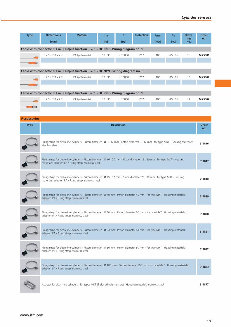
Type Dimensions
[mm]
Material Ub
[V]
f
[Hz]
Protection Iload
[mA]
Ta
[°C]
Draw-ingno.
Orderno.
Cable with connector 0.3 m · Output function · DC PNP · Wiring diagram no. 1
17.5 x 2.8 x 7.7 PA (polyamide) 10...30 > 10000 IP67 100 -25...85 13 MK5301
Cable with connector 0.3 m · Output function · DC NPN · Wiring diagram no. 8
17.5 x 2.8 x 7.7 PA (polyamide) 10...30 > 10000 IP67 100 -25...85 13 MK5307
Cable with connector 0.3 m · Output function · DC PNP · Wiring diagram no. 1
17.5 x 2.8 x 7.7 PA (polyamide) 10...30 > 10000 IP67 100 -25...85 14 MK5302
Accessories
Type Description Orderno.
Fixing strap for clean-line cylinders · Piston diameter · Ø 8...12 mm · Piston diameter 8...12 mm · for type MKT · Housing materials:stainless steel
E11816
Fixing strap for clean-line cylinders · Piston diameter · Ø 16...20 mm · Piston diameter 16...20 mm · for type MKT · Housingmaterials: adapter: PA / Fixing strap: stainless steel
E11817
Fixing strap for clean-line cylinders · Piston diameter · Ø 25...32 mm · Piston diameter 25...32 mm · for type MKT · Housingmaterials: adapter: PA / Fixing strap: stainless steel
E11818
Fixing strap for clean-line cylinders · Piston diameter · Ø 40 mm · Piston diameter 40 mm · for type MKT · Housing materials:adapter: PA / Fixing strap: stainless steel
E11819
Fixing strap for clean-line cylinders · Piston diameter · Ø 50 mm · Piston diameter 50 mm · for type MKT · Housing materials:adapter: PA / Fixing strap: stainless steel
E11820
Fixing strap for clean-line cylinders · Piston diameter · Ø 63 mm · Piston diameter 63 mm · for type MKT · Housing materials:adapter: PA / Fixing strap: stainless steel
E11821
Fixing strap for clean-line cylinders · Piston diameter · Ø 80 mm · Piston diameter 80 mm · for type MKT · Housing materials:adapter: PA / Fixing strap: stainless steel
E11822
Fixing strap for clean-line cylinders · Piston diameter · Ø 100 mm · Piston diameter 100 mm · for type MKT · Housing materials:adapter: PA / Fixing strap: stainless steel
E11823
Adapter for clean-line cylinders · for types MKT (T-slot cylinder sensors) · Housing materials: stainless steel E11877
Cylinder sensors
53www.ifm.com

Type Description Orderno.
Adapter for tie rod / integrated profile cylinders · for types MKT (T-slot cylinder sensors) · Clamping range 5...11 mm · Housingmaterials: aluminium / screw: stainless steel
E11797
Adapter for tie rod / integrated profile cylinders · for types MKT (T-slot cylinder sensors) · Clamping range 9...15 mm · Housingmaterials: aluminium / screw: stainless steel
E11799
Adapter for tie rod / integrated profile cylinders · for types MKT (T-slot cylinder sensors) · Clamping range 14...20 mm · Housingmaterials: aluminium / screw: stainless steel
E11801
Adapter for trapezoidal slot cylinders · for types MKT (T-slot cylinder sensors) · Housing materials: aluminium alloy / set screw:stainless steel
E11796
T-slot adapter for C-slot sensor · for types MKC (C-slot cylinder sensor) for installation in T-slot cylinders · for types MKC · (height 5mm) · Housing materials: diecast zinc / fixing element: stainless steel
E11928
T-slot adapter for C-slot sensor · for types MKC (C-slot cylinder sensor) for installation in T-slot cylinders · for types MKC · (height 7.7mm) · Housing materials: diecast zinc / fixing element: stainless steel
E11914
T-slot cylinder memorisation block · for types MKT (T-slot cylinder sensors) · Housing materials: PA / stainless steel E11798
C-slot cylinder memorisation block · for types MKC (C-slot cylinder sensors) · Housing materials: PA / stainless steel E12004
Clip · for types MKT (T-slot cylinder sensors) · Piston diameter 16 mm · Housing materials: POM / fixture: aluminium / screw: stainlesssteel
E11958
Clip · for types MKT (T-slot cylinder sensors) · Piston diameter 20 mm · Housing materials: POM / fixture: aluminium / screw: stainlesssteel
E11959
Clip · for types MKT (T-slot cylinder sensors) · Piston diameter 25 mm · Housing materials: POM / fixture: aluminium / screw: stainlesssteel
E11960
Clip · for types MKT (T-slot cylinder sensors) · Piston diameter 12 mm · Housing materials: POM / fixture: aluminium / screw: stainlesssteel
E11961
Clip · for types MKT (T-slot cylinder sensors) · Piston diameter 16 mm · Housing materials: POM / fixture: aluminium / screw: stainlesssteel
E11958
Clip · for types MKT (T-slot cylinder sensors) · Piston diameter 20 mm · Housing materials: POM / fixture: aluminium / screw: stainlesssteel
E11959
Cylinder sensors
54www.ifm.com

Wiring diagrams
1
L+
L
1
4
3
2
BN
BK
BU
L+
L
3
L
BN
BU
L+
4
L+
L
1
4
5
N
L1BN
BU
L+
L
6
N
L11
4
L+
L
7
L
BN
BK
BU
L+
8
L+
L
1
4
3
Scale drawings - CAD download: www.ifm.com
1
L
25
5
LED
2
1
M8x
1
37 6,5
5,1
1: Fastening clamp, 2: sensing face
2
M8x
1
L
6,5
5,1
25
5
LED
2
141,5
1: Fastening clamp, 2: sensing face
3
L
M12
x1
25
5
LED
2
1556,5
5,1
1: Fastening clamp, 2: sensing face
4
6,5
5,1
25
5
LED
2
1
1: Fastening clamp, 2: sensing face
5
6,5
5,130,5
5
5,71
1: Fastening clamp
6
30,5
5
L
M12
x1
551
5,7 6,5
5,1
1: Fastening clamp
7
L
M12
x1
25
5
LED
2
1556,5
5,1
1: Fastening clamp, 2: sensing face
8
6,5
5,1
25
5
LED1
2
1: Fastening clamp, 2: sensing face
Cylinder sensors
55www.ifm.com

Scale drawings - CAD download: www.ifm.com
9
L
6,5
5,1
25
5
1
M8x
1
37
2
LED
1: Fastening clamp, 2: sensing face
10
L
M12
x1
255
LED155
2
6,5
5,1
1: Fastening clamp, 2: sensing face
11
6,5
5,1
25
5
1
2
LED55
L
M12
x1
1: Fastening clamp, 2: sensing face
12
17,5
7,7
2,84,8
1
4,2LED
2
1: Fastening clamp, 2: sensing face
13
M8x
1
L
37
17,5
7,7
LED
2,84,8
1 2
4,2
1: Fastening clamp, 2: sensing face
14
L
M8x
1
41,5
17,5
7,7
LED
2,84,8
1 2
4,2
1: Fastening clamp, 2: sensing face
Cylinder sensors
56www.ifm.com

Cylinder sensors
57

58

Safety technology
Selection chart Page
Fail-safe inductive sensors, 2 x OSSD, to IEC62061 SILcl 2 and ISO13849-1 PL d 61
Safety relays for fail-safe sensors 61
Accessories 61
Wiring diagrams 61
Scale drawings - CAD download: www.ifm.com 62
59www.ifm.comwww.ifm.com

Certified to IEC 61508,SIL 2 / SIL 3 and ISO 13849-1 PL d / e.
Safety monitoring of persons and machines.
No coded target required for electronic fail-safe sensors.
Connection of the sensors to safety PLCs, bus systems and switching devices possible.
Series connection of sensors and contacts.
Safety technology
Safety technology in automation has a share of the responsibility for safe human-machine interaction. Fail-safe sensors with safety functions are an important part ofa safety system for persons and machines. For the first time, the operating principleand thus the advantages of inductive sensors can also be used for safety applications.Direct detection of metal solves new applications. Up to now magnetic or mechani-cal counterparts had to be considered in the design. The wear-free non-contactsensing principle and a high protection rating ensure high plant uptime.
Connection and evaluation
No special demands such as shielding, twisted cables or laying separately, are madeon the socket. The sensor is directly connected to existing PLCs or logic modulesusing common existing unshielded 4-pole cables.
The input and output signals of the sensors correspond to DIN EN 61131-2. They aretherefore fully compatible with the inputs and outputs of a PLC. Connection to ifmsafety relays, AS-i Safety at Work, PROFIsafe, Interbus Safety bus systems or safe PLCsand logic modules is equally simple. For the unit family with dynamic pulse detectionthe corresponding software modules are required.
The fail-safe sensors with 2 x PNP output can be connected to approved two-channelsafety relays without cross-monitoring that are suitable for plus-switching non-contact guards. The safety relays from ifm electronic enable functionalities such astwo-hand controls to EN 574 or connection of e-stop devices to DIN EN 574-5-1without extra cost.
Operating principle of intelligent electronic fail-safe sensors
A magnet or coded target is no longer necessary for the function of the fail-safe sen-sor. The fail-safe inductive sensor detects metals such as stainless steel or mild steel.The fail-safe sensor operates with an enable zone which is monitored for targetposition and dwell time.
Limitation of the axisareas of a robot moni-tored by the GG505S.
Connection of thesensors to safety plcs,
bus systems andrelays possible.
Safety technology
60www.ifm.com
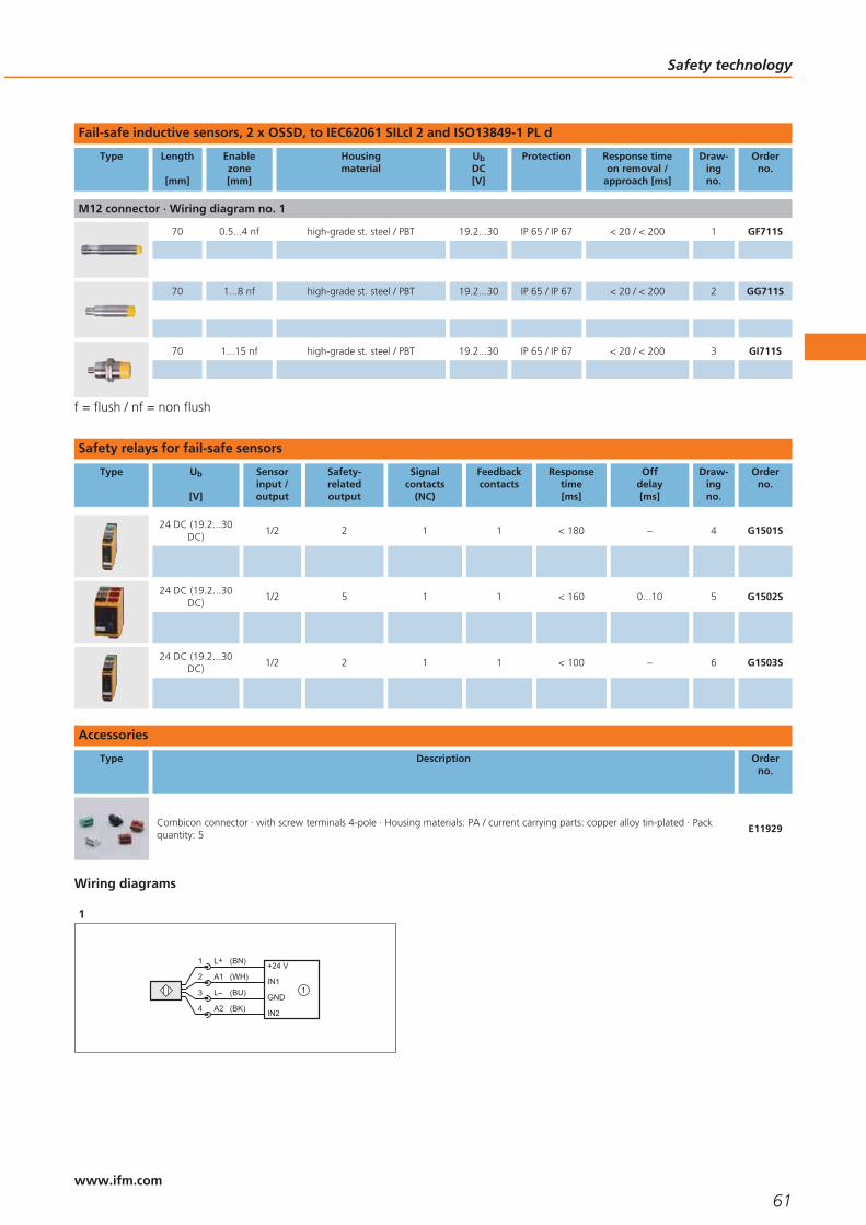
Fail-safe inductive sensors, 2 x OSSD, to IEC62061 SILcl 2 and ISO13849-1 PL d
Type Length
[mm]
Enablezone[mm]
Housingmaterial
UbDC[V]
Protection Response timeon removal /
approach [ms]
Draw-ingno.
Orderno.
M12 connector · Wiring diagram no. 1
70 0.5...4 nf high-grade st. steel / PBT 19.2...30 IP 65 / IP 67 < 20 / < 200 1 GF711S
70 1...8 nf high-grade st. steel / PBT 19.2...30 IP 65 / IP 67 < 20 / < 200 2 GG711S
70 1...15 nf high-grade st. steel / PBT 19.2...30 IP 65 / IP 67 < 20 / < 200 3 GI711S
f = flush / nf = non flush
Safety relays for fail-safe sensors
Type Ub
[V]
Sensorinput /output
Safety-relatedoutput
Signalcontacts
(NC)
Feedbackcontacts
Responsetime[ms]
Offdelay[ms]
Draw-ingno.
Orderno.
24 DC (19.2...30DC)
1/2 2 1 1 < 180 – 4 G1501S
24 DC (19.2...30DC)
1/2 5 1 1 < 160 0...10 5 G1502S
24 DC (19.2...30DC)
1/2 2 1 1 < 100 – 6 G1503S
Accessories
Type Description Orderno.
Combicon connector · with screw terminals 4-pole · Housing materials: PA / current carrying parts: copper alloy tin-plated · Packquantity: 5
E11929
Wiring diagrams
1
(BK)
3
1
4
2
L+
L
(BN)
A2
A1
(BU)
(WH)+24 V
IN1
GND
IN2
1
Safety technology
61www.ifm.com

Scale drawings - CAD download: www.ifm.com
1
45
M12
x1
174
5
M12
x159
70
LED
2
35
M12
x1
LED 2 x 180°
70,5
M18
x1
57
424
10
3
LED 4 x 90°
M30
x1,5
5
45
70
36
M12
x1
15
57
4
35,5
25
100
LED
105
1: Combicon connector with screw terminals
5
105
35,5
114
LED
50
6
25 105
35,5
100
LED
1: screw terminal (supplied)
Safety technology
62www.ifm.com

Safety technology
63

64

Valve sensors
Selection chart Page
Sensors for industrial applications 67
Accessories 67
Scale drawings - CAD download: www.ifm.com 67
Wiring diagrams 67
65www.ifm.comwww.ifm.com

Dual inductive feedback sensors forvalves and actuators.
Straightforward fit to standard actuators.
Compact, weatherproof andlow maintenance.
Optional back wiring option for localsolenoid control.
Versions for network, hazardous areaand conventional wiring.
Valve sensors
In industrial processes where liquids, air or gases are used valves are needed fordosing and control. There is a wide variety of valve types; butterfly or ball valvesbeing the most common quarter-turn types.
These valves are seldom operated manually. Pneumatic valve actuators are normallyused for mechanical positioning. The valve position must be monitored electroni-cally.
Mechanical switches are still often used for position feedback on the actuator shaft.For other solutions several proximity sensors are used together with a switch targetfor position detection. Disadvantage: Mounting is mechanically complex. Duringswitch mounting the signal wires can be reversed when they are connected in thetop-mounted junction box. Where there are temperature fluctuations condensinghumidity leads to corrosion and thus malfunction.
Operating principle
An innovative design eliminates the disadvantages of these conventional solutions. In1992 ifm electronic developed a standard which is now used by many leading actua-tor manufacturers. A round switch target, known as a “puck”, with two metalscrews offset by 90° is mounted on the actuator shaft. The screws are located at adifferent height. A compact dual proximity switch (type IND) with two integral sen-sors detects the upper or lower metal screw depending on the valve position andthus the two switch positions.
Due to the simple construction the system operates safely with no wear at all. It isvirtually resistant to external influence and meets the protection rating IP 67. Undercertain conditions the unit can even be self-cleaning. The sensors are also resistant tomechanical stress such as vibration and shock.
Special design AS-i (T5)
An extended design is the series T5. In addition to the inductive dual sensor, the unitprovides an integrated connection for the solenoid valve. The connection to thecontrol unit is made via a two-wire AS-i cable. The asset: Up to 30 other units can beconnected to this line and separately controlled via the AS-i master.
Feedback: Monitoringof pneumatic and
manual valves mustbe possible.
Valve sensors
66www.ifm.com

Sensors for industrial applications
Type Dimensions
[mm]
Sensingrange[mm]
Material Ub
[V]
Protection fAC / DC
[Hz]
IloadAC / DC
[mA]
Draw-ingno.
Orderno.
Terminals · Output function · DC PNP · Wiring diagram no. 1
33 x 60 x 92 4 nf PA (polyamide) 10...30 IP67 500 100 1 IN5409
f = flush / nf = non flush
Accessories
Type Description Orderno.
Cable gland · M20 x 1.5 · Housing materials: PA 6.6 E12208
Protective cap · M20 x 1.5 · Housing materials: PA 6.6 E12209
Wiring diagrams
1
L
L+2
4
1
34:2:
A2A1
6
7
8
5 IN +
IN -
OUT +
OUT -
1: solenoid valve
Scale drawings - CAD download: www.ifm.com
1
33
92
6,3
18,8
60
7,5
5,5
3060M
20x1
,5
1: sensor 1, 2: sensor 2, 3: LED OUT 1, 4: LED OUT 2
Valve sensors
67www.ifm.com

68

Photoelectric sensorsinfrared / redlight
Selection chart Page
Cylindrical housing OG (M18) BasicLine DC 71
Cylindrical housing OG (M18) PerformanceLine DC 71 - 72
Cylindrical housing OG (M18) BasicLine with lateral sensing face 72
Cylindrical housing OG (M18) WetLine for hygienic and wet areas 72
OG housing with rectangular housing 73
Cylindrical housing OG (M18) BasicLine AC/DC 73
Rectangular housing OH for industrial applications 74
Rectangular housing OJ PerformanceLine, lateral sensing face 74 - 75
Rectangular housing OL for industrial applications 75
Rectangular housing O7 BasicLine 75 - 76
Rectangular housing O5 BasicLine 76
Rectangular housing O5 PerformanceLine 76
Rectangular housing O4 BasicLine 77
Rectangular housing O4 PerformanceLine 77
Accessories 77 - 79
Wiring diagrams 79
Scale drawings - CAD download: www.ifm.com 80
69www.ifm.comwww.ifm.com
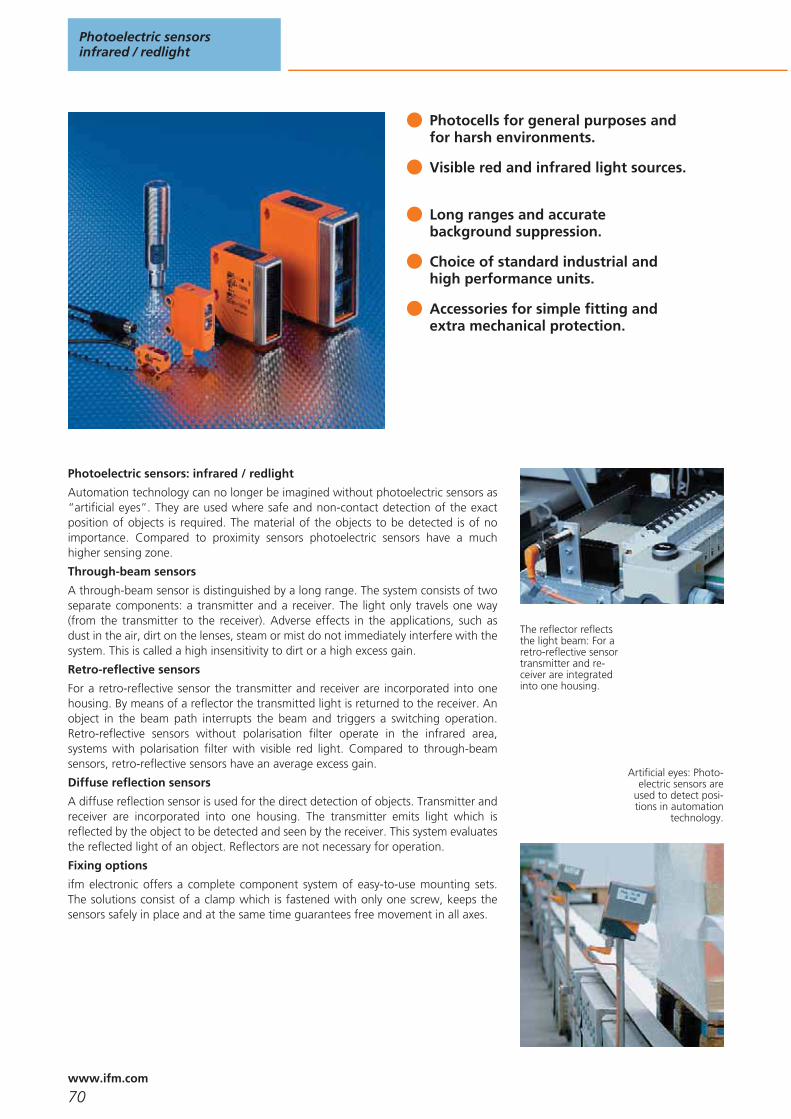
Photocells for general purposes andfor harsh environments.
Visible red and infrared light sources.
Long ranges and accuratebackground suppression.
Choice of standard industrial andhigh performance units.
Accessories for simple fitting andextra mechanical protection.
Photoelectric sensors: infrared / redlight
Automation technology can no longer be imagined without photoelectric sensors as“artificial eyes”. They are used where safe and non-contact detection of the exactposition of objects is required. The material of the objects to be detected is of noimportance. Compared to proximity sensors photoelectric sensors have a muchhigher sensing zone.
Through-beam sensors
A through-beam sensor is distinguished by a long range. The system consists of twoseparate components: a transmitter and a receiver. The light only travels one way(from the transmitter to the receiver). Adverse effects in the applications, such asdust in the air, dirt on the lenses, steam or mist do not immediately interfere with thesystem. This is called a high insensitivity to dirt or a high excess gain.
Retro-reflective sensors
For a retro-reflective sensor the transmitter and receiver are incorporated into onehousing. By means of a reflector the transmitted light is returned to the receiver. Anobject in the beam path interrupts the beam and triggers a switching operation.Retro-reflective sensors without polarisation filter operate in the infrared area,systems with polarisation filter with visible red light. Compared to through-beamsensors, retro-reflective sensors have an average excess gain.
Diffuse reflection sensors
A diffuse reflection sensor is used for the direct detection of objects. Transmitter andreceiver are incorporated into one housing. The transmitter emits light which isreflected by the object to be detected and seen by the receiver. This system evaluatesthe reflected light of an object. Reflectors are not necessary for operation.
Fixing options
ifm electronic offers a complete component system of easy-to-use mounting sets.The solutions consist of a clamp which is fastened with only one screw, keeps thesensors safely in place and at the same time guarantees free movement in all axes.
The reflector reflectsthe light beam: For aretro-reflective sensortransmitter and re-ceiver are integratedinto one housing.
Artificial eyes: Photo-electric sensors are
used to detect posi-tions in automation
technology.
Photoelectric sensorsinfrared / redlight
70www.ifm.com

Cylindrical housing OG (M18) BasicLine DC
Type Operating principle Sensingrange
Spot Ø atmax.range[mm]
OutputH = light-onD = dark-on
Ub
[V]
Wiringdiagram
no.
Draw-ingno.
Orderno.
Through-beam sensor · Type OGE M18 x 1 · M12 connector · plastics · DC
Receiver 8 m – D PNP 10...30 1 1 OGE100
Through-beam sensor · Type OGS M18 x 1 · M12 connector · metal · DC
Transmitter 8 m 600 – 10...30 2 1 OGS100
Through-beam sensor · Type OGE M18 x 1 · M12 connector · high-grade stainless steel · DC
Receiver 20 m – D PNP 10...36 1 2 OGE200
Through-beam sensor · Type OGS M18 x 1 · M12 connector · high-grade stainless steel · DC
Transmitter 20 m 800 – 10...36 2 2 OGS200
Retro-reflective sensor · Type OGP M18 x 1 · M12 connector · plastics · DC
Polarisation filter 0.05...2.5 m 200 D PNP 10...30 1 1 OGP100
Retro-reflective sensor · Type OGP M18 x 1 · M12 connector · high-grade stainless steel · DC
Polarisation filter 0.03...4 m 160 D PNP 10...36 1 2 OGP200
Polarisation filter 0.03...4 m 160 H PNP 10...36 3 2 OGP201
Diffuse reflection sensor · Type OGT M18 x 1 · M12 connector · plastics · DC
Diffuse reflection sensor 10...400 mm 25 H PNP 10...30 1 3 OGT100
Diffuse reflection sensor · Type OGH M18 x 1 · M12 connector · high-grade stainless steel · DC
Background suppression 15...250 mm 15 H PNP 10...36 1 4 OGH200
Cylindrical housing OG (M18) PerformanceLine DC
Type Operating principle Sensingrange
Spot Ø atmax.range[mm]
OutputH = light-onD = dark-on
Ub
[V]
Wiringdiagram
no.
Draw-ingno.
Orderno.
Through-beam sensor · Type OGS M18 x 1 · M12 connector · high-grade stainless steel · DC
Transmitter 25 m 1000 – 10...36 2 5 OGS500
Through-beam sensor · Type OGE M18 x 1 · M12 connector · high-grade stainless steel · DC
Receiver 25 m – H/D PNP 10...36 1 6 OGE500
Photoelectric sensorsinfrared / redlight
71www.ifm.com

Type Operating principle Sensingrange
Spot Ø atmax.range[mm]
OutputH = light-onD = dark-on
Ub
[V]
Wiringdiagram
no.
Draw-ingno.
Orderno.
Retro-reflective sensor · Type OGP M18 x 1 · M12 connector · high-grade stainless steel · DC
Polarisation filter 0.03...5 m 200 H/D PNP 10...36 1 6 OGP500
Diffuse reflection sensor · Type OGH M18 x 1 · M12 connector · high-grade stainless steel · DC
Background suppression 15...300 mm 25 H/D PNP 10...36 1 6 OGH500
Cylindrical housing OG (M18) BasicLine with lateral sensing face
Type Operating principle Sensingrange
Spot Ø atmax.range[mm]
OutputH = light-onD = dark-on
Ub
[V]
Wiringdiagram
no.
Draw-ingno.
Orderno.
Through-beam sensor · Type OGS · M12 connector · high-grade stainless steel · DC
Transmitter 9 m < 3000 – 10...30 2 7 OG5129
Through-beam sensor · Type OGE · M12 connector · high-grade stainless steel · DC
Receiver 9 m – H PNP 10...30 4 7 OG5127
Receiver 9 m – D PNP 10...30 5 7 OG5128
Retro-reflective sensor · Type OGP · M12 connector · high-grade stainless steel · DC
Polarisation filter 3 m < 96 H PNP 10...30 4 7 OG5125
Polarisation filter 3 m < 96 D PNP 10...30 5 7 OG5126
Diffuse reflection sensor · Type OGH · M12 connector · high-grade stainless steel · DC
Background suppression 100 mm < 16 H PNP 10...30 4 8 OG5123
Background suppression 200 mm < 28 H PNP 10...30 4 8 OG5124
Cylindrical housing OG (M18) WetLine for hygienic and wet areas
Type Operating principle Sensingrange
Spot Ø atmax.range[mm]
OutputH = light-onD = dark-on
Ub
[V]
Wiringdiagram
no.
Draw-ingno.
Orderno.
Retro-reflective sensor · Type OGP M18 x 1 · M12 connector · high-grade stainless steel · DC
Polarisation filter 0.03...4 m 160 D PNP 10...36 1 2 OGP300
Diffuse reflection sensor · Type OGH M18 x 1 · M12 connector · high-grade stainless steel · DC
Background suppression 100 mm 8 H PNP 10...36 1 9 OGH300
Photoelectric sensorsinfrared / redlight
72www.ifm.com
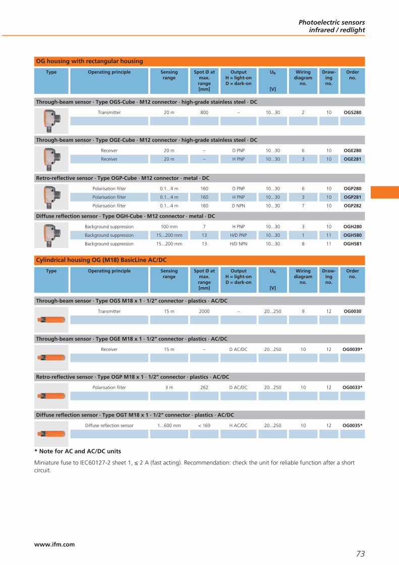
OG housing with rectangular housing
Type Operating principle Sensingrange
Spot Ø atmax.range[mm]
OutputH = light-onD = dark-on
Ub
[V]
Wiringdiagram
no.
Draw-ingno.
Orderno.
Through-beam sensor · Type OGS-Cube · M12 connector · high-grade stainless steel · DC
Transmitter 20 m 800 – 10...30 2 10 OGS280
Through-beam sensor · Type OGE-Cube · M12 connector · high-grade stainless steel · DC
Receiver 20 m – D PNP 10...30 6 10 OGE280
Receiver 20 m – H PNP 10...30 3 10 OGE281
Retro-reflective sensor · Type OGP-Cube · M12 connector · metal · DC
Polarisation filter 0.1...4 m 160 D PNP 10...30 6 10 OGP280
Polarisation filter 0.1...4 m 160 H PNP 10...30 3 10 OGP281
Polarisation filter 0.1...4 m 160 D NPN 10...30 7 10 OGP282
Diffuse reflection sensor · Type OGH-Cube · M12 connector · metal · DC
Background suppression 100 mm 7 H PNP 10...30 3 10 OGH280
Background suppression 15...200 mm 13 H/D PNP 10...30 1 11 OGH580
Background suppression 15...200 mm 13 H/D NPN 10...30 8 11 OGH581
Cylindrical housing OG (M18) BasicLine AC/DC
Type Operating principle Sensingrange
Spot Ø atmax.range[mm]
OutputH = light-onD = dark-on
Ub
[V]
Wiringdiagram
no.
Draw-ingno.
Orderno.
Through-beam sensor · Type OGS M18 x 1 · 1/2“ connector · plastics · AC/DC
Transmitter 15 m 2000 – 20...250 9 12 OG0030
Through-beam sensor · Type OGE M18 x 1 · 1/2“ connector · plastics · AC/DC
Receiver 15 m – D AC/DC 20...250 10 12 OG0039*
Retro-reflective sensor · Type OGP M18 x 1 · 1/2“ connector · plastics · AC/DC
Polarisation filter 3 m 262 D AC/DC 20...250 10 12 OG0033*
Diffuse reflection sensor · Type OGT M18 x 1 · 1/2“ connector · plastics · AC/DC
Diffuse reflection sensor 1...600 mm < 169 H AC/DC 20...250 10 12 OG0035*
* Note for AC and AC/DC units
Miniature fuse to IEC60127-2 sheet 1, ≤ 2 A (fast acting). Recommendation: check the unit for reliable function after a shortcircuit.
Photoelectric sensorsinfrared / redlight
73www.ifm.com

Rectangular housing OH for industrial applications
Type Operating principle Sensingrange
Spot Ø atmax.range[mm]
OutputH = light-onD = dark-on
Ub
[V]
Wiringdiagram
no.
Draw-ingno.
Orderno.
Through-beam sensor · Type OHS · Cable with connector 0.2 m · plastics · DC
Transmitter 1.2 m 10 – 10...30 2 13 OH5012
Through-beam sensor · Type OHE · Cable with connector 0.2 m · plastics · DC
Receiver 1.2 m – D PNP 10...30 6 13 OH5003
Retro-reflective sensor · Type OHP · Cable with connector 0.2 m · plastics · DC
Polarisation filter 0.8 m 10 D PNP 10...30 6 14 OH5011
Diffuse reflection sensor · Type OHN · Cable with connector 0.2 m · plastics · DC
Diffuse reflection sensor 2...50 mm 3.5 H PNP 10...30 3 15 OH5005
Diffuse reflection sensor · Type OHH · Cable with connector 0.2 m · plastics · DC
Background suppression 1...30 mm 4.5 H PNP 10...30 3 15 OH5007
Rectangular housing OJ PerformanceLine, lateral sensing face
Type Operating principle Sensingrange
Spot Ø atmax.range[mm]
OutputH = light-onD = dark-on
Ub
[V]
Wiringdiagram
no.
Draw-ingno.
Orderno.
Through-beam sensor · Type OJE · M8 connector · plastics · DC
Receiver 10 m – H/D NPN 10...30 11 16 OJ5032
Retro-reflective sensor · Type OJP · M8 connector · plastics · DC
Polarisation filter 0...2 m 64 H/D NPN 10...30 11 16 OJ5027
Diffuse reflection sensor · Type OJB · M8 connector · plastics · DC
Diffuse reflection sensor 1...600 mm 60 H/D NPN 10...30 11 17 OJ5023
Diffuse reflection sensor 1...1000 mm 150 H/D PNP 10...30 12 17 OJ5071
Through-beam sensor · Type OJS · M8 connector · plastics · DC
Transmitter 10 m 1000 – 10...30 2 18 OJ5130
Through-beam sensor · Type OJE · M8 connector · plastics · DC
Receiver 10 m – H/D PNP 10...30 12 18 OJ5131
Photoelectric sensorsinfrared / redlight
74www.ifm.com
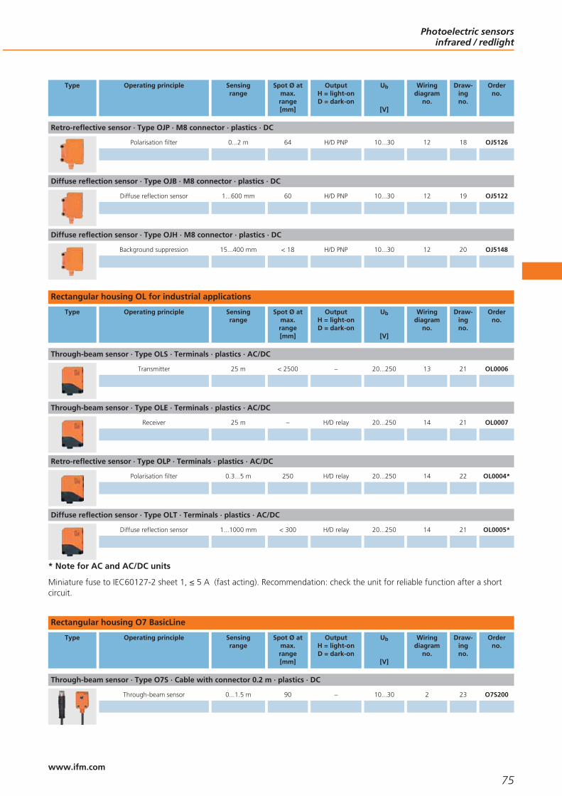
Type Operating principle Sensingrange
Spot Ø atmax.range[mm]
OutputH = light-onD = dark-on
Ub
[V]
Wiringdiagram
no.
Draw-ingno.
Orderno.
Retro-reflective sensor · Type OJP · M8 connector · plastics · DC
Polarisation filter 0...2 m 64 H/D PNP 10...30 12 18 OJ5126
Diffuse reflection sensor · Type OJB · M8 connector · plastics · DC
Diffuse reflection sensor 1...600 mm 60 H/D PNP 10...30 12 19 OJ5122
Diffuse reflection sensor · Type OJH · M8 connector · plastics · DC
Background suppression 15...400 mm < 18 H/D PNP 10...30 12 20 OJ5148
Rectangular housing OL for industrial applications
Type Operating principle Sensingrange
Spot Ø atmax.range[mm]
OutputH = light-onD = dark-on
Ub
[V]
Wiringdiagram
no.
Draw-ingno.
Orderno.
Through-beam sensor · Type OLS · Terminals · plastics · AC/DC
Transmitter 25 m < 2500 – 20...250 13 21 OL0006
Through-beam sensor · Type OLE · Terminals · plastics · AC/DC
Receiver 25 m – H/D relay 20...250 14 21 OL0007
Retro-reflective sensor · Type OLP · Terminals · plastics · AC/DC
Polarisation filter 0.3...5 m 250 H/D relay 20...250 14 22 OL0004*
Diffuse reflection sensor · Type OLT · Terminals · plastics · AC/DC
Diffuse reflection sensor 1...1000 mm < 300 H/D relay 20...250 14 21 OL0005*
* Note for AC and AC/DC units
Miniature fuse to IEC60127-2 sheet 1, ≤ 5 A (fast acting). Recommendation: check the unit for reliable function after a shortcircuit.
Rectangular housing O7 BasicLine
Type Operating principle Sensingrange
Spot Ø atmax.range[mm]
OutputH = light-onD = dark-on
Ub
[V]
Wiringdiagram
no.
Draw-ingno.
Orderno.
Through-beam sensor · Type O7S · Cable with connector 0.2 m · plastics · DC
Through-beam sensor 0...1.5 m 90 – 10...30 2 23 O7S200
Photoelectric sensorsinfrared / redlight
75www.ifm.com

Type Operating principle Sensingrange
Spot Ø atmax.range[mm]
OutputH = light-onD = dark-on
Ub
[V]
Wiringdiagram
no.
Draw-ingno.
Orderno.
Through-beam sensor · Type O7E · Cable with connector 0.2 m · plastics · DC
Through-beam sensor 0...1.5 m – D PNP 10...30 6 24 O7E200
Retro-reflective sensor · Type O7P · Cable with connector 0.2 m · plastics · DC
Polarisation filter 0.03...1 m 55 D PNP 10...30 6 25 O7P200
Diffuse reflection sensor · Type O7H · Cable with connector 0.2 m · plastics · DC
Background suppression 1...30 mm 2.5 H PNP 10...30 3 26 O7H200
Background suppression 0...50 mm 2.5 H PNP 10...30 3 26 O7H202
Background suppression 0...100 mm 7 H PNP 10...30 3 26 O7H204
Rectangular housing O5 BasicLine
Type Operating principle Sensingrange
Spot Ø atmax.range[mm]
OutputH = light-onD = dark-on
Ub
[V]
Wiringdiagram
no.
Draw-ingno.
Orderno.
Through-beam sensor · Type O5S · M12 connector · plastics · DC
Transmitter 20 m 500 – 10...36 2 27 O5S200
Through-beam sensor · Type O5E · M12 connector · plastics · DC
Receiver 20 m – D PNP 10...36 6 27 O5E200
Retro-reflective sensor · Type O5P · M12 connector · plastics · DC
Polarisation filter 0.1...7 m 175 D PNP 10...36 6 28 O5P200
Diffuse reflection sensor · Type O5H · M12 connector · plastics · DC
Background suppression 50...1400 mm 50 H PNP 10...36 3 29 O5H200
Rectangular housing O5 PerformanceLine
Type Operating principle Sensingrange
Spot Ø atmax.range[mm]
OutputH = light-onD = dark-on
Ub
[V]
Wiringdiagram
no.
Draw-ingno.
Orderno.
Diffuse reflection sensor · Type O5H · M12 connector · plastics · DC
Background suppression 50...1800 mm 50 H/D PNP 10...36 1 30 O5H500
Photoelectric sensorsinfrared / redlight
76www.ifm.com

Rectangular housing O4 BasicLine
Type Operating principle Sensingrange
Spot Ø atmax.range[mm]
OutputH = light-onD = dark-on
Ub
[V]
Wiringdiagram
no.
Draw-ingno.
Orderno.
Retro-reflective sensor · Type O4P · M12 connector · plastics · DC
Polarisation filter 0.3...18 m 500 D PNP 10...36 6 31 O4P200
Rectangular housing O4 PerformanceLine
Type Operating principle Sensingrange
Spot Ø atmax.range[mm]
OutputH = light-onD = dark-on
Ub
[V]
Wiringdiagram
no.
Draw-ingno.
Orderno.
Through-beam sensor · Type O4S · M12 connector · plastics · DC
Transmitter 80 m 2400 – 10...36 2 32 O4S500
Through-beam sensor · Type O4E · M12 connector · plastics · DC
Receiver 80 m – H/D PNP 10...36 1 33 O4E500
Retro-reflective sensor · Type O4P · M12 connector · plastics · DC
Polarisation filter 0.3...22 m 660 H/D PNP 10...36 1 34 O4P500
Diffuse reflection sensor · Type O4H · M12 connector · plastics · DC
Background suppression 100...2600 mm 50 H/D PNP 10...36 1 35 O4H500
Accessories
Type Description Orderno.
Prismatic reflector · Ø 25 mm · round · fixing by screw · for type OA, OC, OE, OF, OG, OI, OM, OR, OS, OT, OU · Housing materials:plastics
E20953
Prismatic reflector · Ø 35 mm · round · fixing by screw · for type OA, OC, OE, OF, OG, OI, OM, OR, OS, OT, OU · Housing materials:plastics
E20954
Prismatic reflector · Ø 42 mm · round · for type O5P, OA, OC, OE, OF, OG, OH, OI, OJ, OL, OM, OR, OS, OT, OU · Housing materials:plastics
E20004
Prismatic reflector · Ø 50 mm · round · fixing by screw · for type OA, OC, OE OF, OG, OH, OI, OJ, OM, OR, OS, OS, OT, OU ·Housing materials: plastics
E20956
Prismatic reflector · Ø 80 mm · round · for type O4P, O5P, OG, OJ, OA, OC, OE OF, OH, OI, OM, OR, OS, OT, OU · Housingmaterials: plastics
E20005
Photoelectric sensorsinfrared / redlight
77www.ifm.com
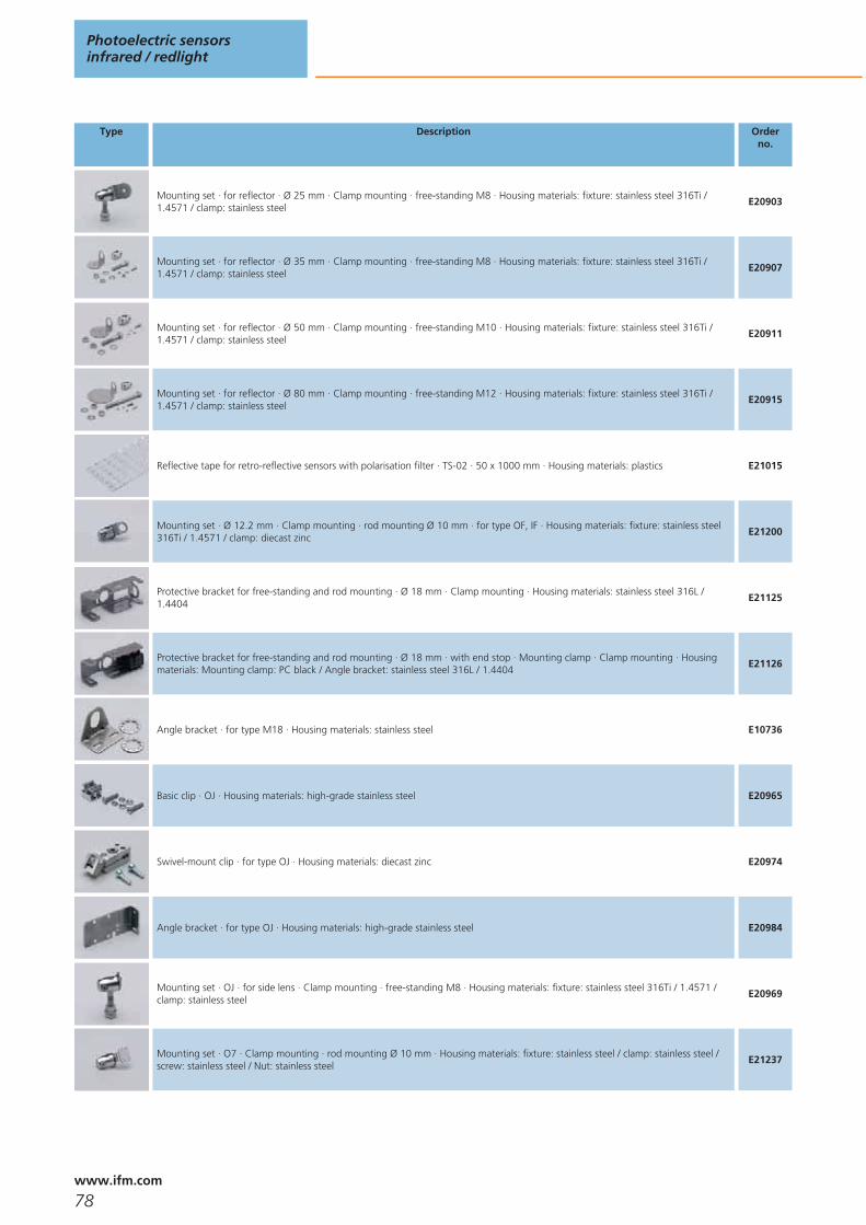
Type Description Orderno.
Mounting set · for reflector · Ø 25 mm · Clamp mounting · free-standing M8 · Housing materials: fixture: stainless steel 316Ti /1.4571 / clamp: stainless steel
E20903
Mounting set · for reflector · Ø 35 mm · Clamp mounting · free-standing M8 · Housing materials: fixture: stainless steel 316Ti /1.4571 / clamp: stainless steel
E20907
Mounting set · for reflector · Ø 50 mm · Clamp mounting · free-standing M10 · Housing materials: fixture: stainless steel 316Ti /1.4571 / clamp: stainless steel
E20911
Mounting set · for reflector · Ø 80 mm · Clamp mounting · free-standing M12 · Housing materials: fixture: stainless steel 316Ti /1.4571 / clamp: stainless steel
E20915
Reflective tape for retro-reflective sensors with polarisation filter · TS-02 · 50 x 1000 mm · Housing materials: plastics E21015
Mounting set · Ø 12.2 mm · Clamp mounting · rod mounting Ø 10 mm · for type OF, IF · Housing materials: fixture: stainless steel316Ti / 1.4571 / clamp: diecast zinc
E21200
Protective bracket for free-standing and rod mounting · Ø 18 mm · Clamp mounting · Housing materials: stainless steel 316L /1.4404
E21125
Protective bracket for free-standing and rod mounting · Ø 18 mm · with end stop · Mounting clamp · Clamp mounting · Housingmaterials: Mounting clamp: PC black / Angle bracket: stainless steel 316L / 1.4404
E21126
Angle bracket · for type M18 · Housing materials: stainless steel E10736
Basic clip · OJ · Housing materials: high-grade stainless steel E20965
Swivel-mount clip · for type OJ · Housing materials: diecast zinc E20974
Angle bracket · for type OJ · Housing materials: high-grade stainless steel E20984
Mounting set · OJ · for side lens · Clamp mounting · free-standing M8 · Housing materials: fixture: stainless steel 316Ti / 1.4571 /clamp: stainless steel
E20969
Mounting set · O7 · Clamp mounting · rod mounting Ø 10 mm · Housing materials: fixture: stainless steel / clamp: stainless steel /screw: stainless steel / Nut: stainless steel
E21237
Photoelectric sensorsinfrared / redlight
78www.ifm.com
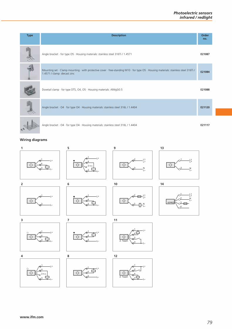
Type Description Orderno.
Angle bracket · for type O5 · Housing materials: stainless steel 316Ti / 1.4571 E21087
Mounting set · Clamp mounting · with protective cover · free-standing M10 · for type O5 · Housing materials: stainless steel 316Ti /1.4571 / clamp: diecast zinc
E21084
Dovetail clamp · for type DTS, O4, O5 · Housing materials: AlMgSi0.5 E21088
Angle bracket · O4 · for type O4 · Housing materials: stainless steel 316L / 1.4404 E21120
Angle bracket · O4 · for type O4 · Housing materials: stainless steel 316L / 1.4404 E21117
Wiring diagrams
1
L+
L
1
4
3
2
1
3
L+
L
3
L+
L
1
4
3
4
L
L+4
2 n.c.
1
3
5
L+4
2 n.c.
1
3 L
6
L+
L
1
4
3
7
L+
L
1
4
3
8
L+
L
1
4
3
9
2
3
L1
N
L+
L
10
2
3
L1
N
L+
L
11
L+
2
4
1
3 L2: Teach
12
L+2
4
1
3 L2: Teach
13
L1L+
L
1
N2
14
L+
L
L1
N2
3
1
4
Photoelectric sensorsinfrared / redlight
79www.ifm.com

Scale drawings - CAD download: www.ifm.com
1
M18
x1
M12
x134
44LED
424
3127,5
2M
18x1
M12
x1
4047
6049
LED 4 x 90°4
24
3
M18
x1
M12
x1
3444
21,4
LED
424
316,5
1
1: with pot.
4
M18
x1
M12
x1
44
59
7261
LED 4 x 90°
50
1
424
1: with pot.
5
M18
x1
M12
x1
3459
7261
LED 4 x 90°4
24
6
M18
x1
M12
x1
3459
7261
LED 4 x 90°
1
424
1: Programming buttons
7
14,5
24
M18 x1
M12 x1
70,159
,3344
16
LED 4 x 90°
8,2
8
LED 4 x 90°
13,6
75
M18 x1
M12 x1
646229
419
9,7
27
24
9
M18
x1
M12
x144
59
7261
LED 4 x 90°4
24
10
18LEDs
38
M18
x1
M12 x1
11,5
35,415,9
24,1
52
243,3
11
3,3
M18
x1
M12 x1
11,5
35,415,9
24,1
52
24
LEDs
1
18
38
1: setting pushbuttons
Photoelectric sensorsinfrared / redlight
80www.ifm.com
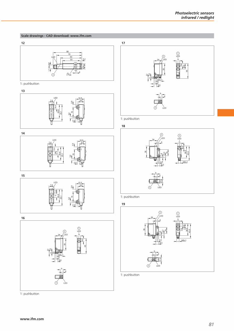
Scale drawings - CAD download: www.ifm.com
12
766453
M18
x1
4
5,2
86
24
LED
"20U
NF
21
1
1: pushbutton
13
3,9 9,6
12,5
3,2 15
2,9
7,6
6,4
20,6
25,1
LED
14
3,9 9,6
12,5
3,2 15
2,9
7,6
6,4
20,6
25,15,
7
LED
15
3,9 9,6
12,5
3,2 15
2,9
7,6
7,2
20,6
25,15
LED
16
45
11
LED
8,2
1
24
3,2
3,1
LED
35
M8x1
8,83,1
1
9
LED
4
1
1: pushbutton
17
11
LED
7,616
,645
1
24
3,2
3,1
LED
35
M8x1
8,83,1
1
9
LED
4
1
1: pushbutton
18
1
9
LED
4
11,6
M8x1
1
36,5
11
LED
8,2
43,5
1
24LED
35
8,5
1,8 5,
3 19
3,5
5
1: pushbutton
19
9
LED
4
11,6
1
24LED
35
8,5
1,8 5,
3 19
3,5
5
1
M8x1
36,5
11
LED
43,57,
6 16,6
1
1: pushbutton
Photoelectric sensorsinfrared / redlight
81www.ifm.com

Scale drawings - CAD download: www.ifm.com
20
24LED
35
8,5
1,8 5,
3 19
3,5
5
1
9
LED
4
11,6
1
19,5
M8x1
36,5
11
LED
43,5
1
9,5
1: pushbutton
21
27LED
1031
75
LED
1
6
62
50
49
5,5
6
LED
8,6
1
1: pushbutton
22
6
62
50
49
5,5
6
8,6
LED
127
LED
1018
13 75
LED
1
1: pushbutton
23
9
15
14,1
LED 9
26 20,3
2,7
M3
24
9
15
26 20,3
14,12,7
M3
LED 9
25
9
15
7,6
6,5
LED 9
26 20,3
2,7
M3
26
9
15
6,5
7,8
LED 926 20
,32,
7
M3
27
LED
15,4
18,2
M12 x1
17
5x9
625 1
56
6,446,8
25
70,3
5
LED
6
1
1: When a M5 mounting screw is used, the max. tightening torque is2 Nm.
Photoelectric sensorsinfrared / redlight
82www.ifm.com

Scale drawings - CAD download: www.ifm.com
28
18,2
M12 x1
1736
,5
LED
15,4
5x9
625 1
56
6,446,8
25
70,3
5
LED
6
1
1: When a M5 mounting screw is used, the max. tightening torque is2 Nm.
29
1
38
10
1
LED
24,3
15,4
18,2
M12 x1
19,5
37
5x9
625 2
56
6,446,8
25
70,3
5
1
LED
6
2
1: with pot., 2: When a M5 mounting screw is used, the max. tighte-ning torque is 2 Nm.
30
18,2
M12 x1
19,5
37
1
LED
30,5
24,3
15,4
5x9
625 2
56
6,446,8
25
70,3
5
1
LED
6
2
1: Programming buttons, 2: When a M5 mounting screw is used, themax. tightening torque is 2 Nm.
31
7,963,8
LED
40
5
8,5
74,4
86,2
1
8,5
40
5x10
1
M12 x1
27
21,1
50,9
LED
29,5
1: When a M5 mounting screw is used, the max. tightening torque is2 Nm.
32
7,963,8
LED
40
5
8,5
74,4
86,2
1
8,5
40
5x10
1
M12 x1
27
21,1
LED
29,5
1: When a M5 mounting screw is used, the max. tightening torque is2 Nm.
Photoelectric sensorsinfrared / redlight
83www.ifm.com

Scale drawings - CAD download: www.ifm.com
33
7,963,8
LED40
5
8,5
74,4
86,2
1
8,5
40
5x10
1
29,5 44
,538
,3
2
LED
M12 x1
27
21,2
1: When a M5 mounting screw is used, the max. tightening torque is2 Nm., 2: Programming buttons
34
7,963,8
LED
40
5
8,5
74,4
86,2
1
8,5
40
5x10
1
29,5 44
,538
,3
2
LED
M12 x1
27
21,2
23,5
1: When a M5 mounting screw is used, the max. tightening torque is2 Nm., 2: Programming buttons
35
7,963,8
LED
40
5
8,5
74,4
86,2
1
8,5
40
5x10
1
29,5 44
,538
,3
2
LED
M12 x1
2725
,319
,7
1: When a M5 mounting screw is used, the max. tightening torque is2 Nm., 2: Programming buttons
Photoelectric sensorsinfrared / redlight
84www.ifm.com

Photoelectric sensorsinfrared / redlight
85

86

Photoelectric sensorslaser
Selection chart Page
Cylindrical housing OG (M18) Laser PerformanceLine 89
Rectangular housing OJ Laser PerformanceLine, lateral sensing face 89
Rectangular housing O1 Laser PerformanceLine with background suppression 89
Accessories 89 - 90
Scale drawings - CAD download: www.ifm.com 90
Wiring diagrams 90
87www.ifm.comwww.ifm.com

Safe class 2 laser with visible lightfor ease of alignment.
Detect objects smaller than 1 mm across.
Long range versions for measurementup to 60 m.
Accurate and repeatable switchpoint setting.
Fine ajustment mounting bracketsfor easy installation.
Photoelectric sensors: laser
Laser systems are used where detection of small objects or precise positioning isrequired. They are available as through-beam sensors, retro-reflective sensors ordiffuse reflection sensors.
Laser light consists of light waves of identical length which have a defined phase rela-tion (coherence). This results in an important feature of laser systems, that is thealmost parallel light beam. Result: Due to the small angle of divergence long rangesof up to 60 metres can be achieved. The laser spot which is also clearly visible atdaylight simplifies the alignment of the system. Apart from the advantages somepoints have to be taken into account for the selection of the suitable optical system:compared to standard sensors the laser sensors have a reduced temperature range(-10...50 °C). In view of the small light spot and the often high ranges the system ismore sensitive to vibrations than standard sensors.
Mounting aids
The ifm laser sensors offer a useful function for easier alignment: The laser power isincreased during adjustment: This leads to a particularly bright laser spot which en-ables safe alignment from a distance even at daylight.
How dangerous are laser sensors?
Due to the small angle of divergence laser beams are focussed on a small area. Theenergy and power density on this area is extremely high. ifm laser sensors complywith the European standard EN 60825 or the international standard IEC 60825.These standards describe the operation of laser systems.
Coherent: Lasersensors emit light ofa defined wave lengthand the same phaseposition.
Photoelectric sensorslaser
88www.ifm.com

Cylindrical housing OG (M18) Laser PerformanceLine
Type Operating principle Sensingrange
Spot Ø atmax.range[mm]
OutputH = light-onD = dark-on
Ub
[V]
Wiringdiagram
no.
Draw-ingno.
Orderno.
Through-beam sensor · Type OGSL M18 x 1 · M12 connector · high-grade stainless steel · DC
Transmitter 60 m 150 – 10...36 1 1 OGS700
Through-beam sensor · Type OGEL M18 x 1 · M12 connector · high-grade stainless steel · DC
Receiver 60 m – H/D PNP 10...36 2 2 OGE700
Retro-reflective sensor · Type OGPL M18 x 1 · M12 connector · high-grade stainless steel · DC
Polarisation filter 0.2...15 m 40 H/D PNP 10...36 2 2 OGP700
Diffuse reflection sensor · Type OGHL M18 x 1 · M12 connector · high-grade stainless steel · DC
Background suppression 20...200 mm 1.2 H/D PNP 10...36 2 2 OGH700
Rectangular housing OJ Laser PerformanceLine, lateral sensing face
Type Operating principle Sensingrange
Spot Ø atmax.range[mm]
OutputH = light-onD = dark-on
Ub
[V]
Wiringdiagram
no.
Draw-ingno.
Orderno.
Diffuse reflection sensor · Type OJHL · M8 connector · plastics · DC
Background suppression 7...150 mm 0.8 H/D PNP 10...30 3 3 OJ5158
Background suppression 15...200 mm 2x1 H/D PNP 10...30 3 4 OJ5154
Rectangular housing O1 Laser PerformanceLine with background suppression
Type Operating principle Measuringrange
Light spotdiameter
[mm]
Ub
[V]
Currentconsumption
[mA]
Sampling rate /switching frequency
[Hz]
Draw-ingno.
Orderno.
Optical distance sensor · Type O1DL · M12 connector · metal · DC
Background suppression 0.2...10 m 6 10...30 150 5 5 O1D101
Accessories
Type Description Orderno.
Prismatic reflector · Ø 19 mm · round · fixing by screw · M3 · for laser units · for type OGPL, OJPL, OLPL · Housing materials: screw:stainless steel 316 / 1.4401 / spring washer: stainless steel 316 / 1.4401 / Nut: stainless steel 316 / 1.4401 / front plate: PMMA /base: ABS
E20993
Prismatic reflector · 30 x 20 mm · angular · for laser units · for type OGPL, OJPL, OLPL · Housing materials: front plate: PMMA / base:ABS
E20994
Photoelectric sensorslaser
89www.ifm.com

Type Description Orderno.
Prismatic reflector · 50 x 50 mm · angular · for laser sensors and glass / film detection sensors · Housing materials: plastics E20722
Swivel-mount clip · for type OJ · Housing materials: diecast zinc E20974
Mounting set · Clamp mounting · rod mounting Ø 12 mm · for type O1D, O2D · Housing materials: fixture: stainless steel / clamp:stainless steel / screws: stainless steel / Nut: high-grade stainless steel
E2D101
Wiring diagrams
1
1
3
L+
L
2
L+
L
1
4
3
3
L+2
4
1
3 L2: Teach
Scale drawings - CAD download: www.ifm.com
1
M18
x1
M12
x1
3459
7261
LED 4 x 90°4
24
2
M18
x1
M12
x1
3459
7261
LED 4 x 90°
1
424
1: Programming buttons
3
24LED
35
8,5
1,8 5,
3 19
3,5
5
1
9
LED
4
11,6
1
M8x1
36,5
11
LED
43,5
1
9,5
15,5
1: pushbutton
Photoelectric sensorslaser
90www.ifm.com
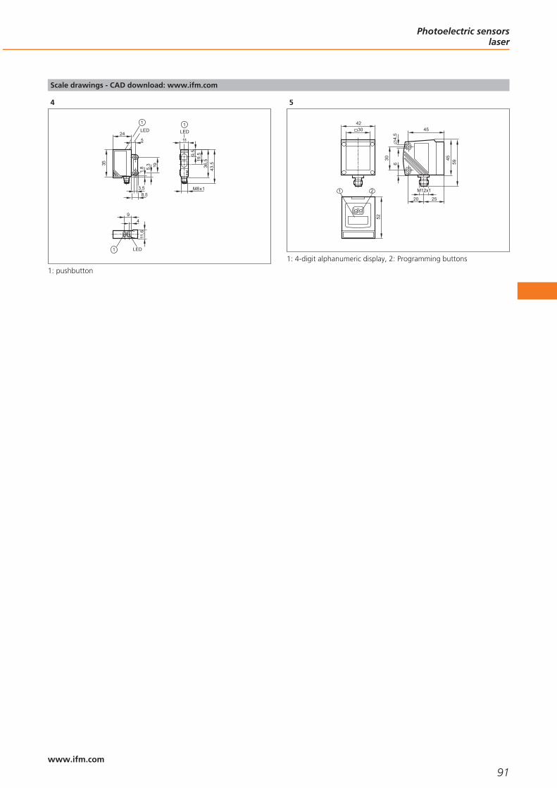
Scale drawings - CAD download: www.ifm.com
4
24LED
35
8,5
1,8 5,
3 19
3,5
5
1
9
LED
4
11,6
1
19,5
M8x1
36,5
11
LED
43,5
1
9,5
1: pushbutton
5
52
1 2
30
45
2520
4,5
6
4559
42
M12x1
30
1: 4-digit alphanumeric display, 2: Programming buttons
Photoelectric sensorslaser
91www.ifm.com

92

Photoelectric sensorsfibre optics
Selection chart Page
OOF amplifiers for acrylic fibre optics 95
OBF amplifiers for acrylic fibre optics 95
Acrylic fibre optics for OBF / OOF housings, through-beam system 95
Acrylic fibre optics for OBF / OOF housings, diffuse reflection system 95
Acrylic fibre optics for OBF / OOF housings, through-beam system, can be cut to length 96
Acrylic fibre optics for OBF / OOF housings, diffuse reflection system, can be cut to length 96
Acrylic fibres on a reel for OBF housing 96
Accessories 96
Wiring diagrams 96 - 97
Scale drawings - CAD download: www.ifm.com 97 - 98
93www.ifm.comwww.ifm.com

Acrylic and glass fibre optic sensingheads and amplifiers.
Can be used in areas where spaceand access is restricted.
Fibres for high temperatures and usewith aggressive chemicals.
Multi-channel amplifiers with displayand logic functions.
Simplified wiring and reducedspace requirement.
Photoelectric sensors: fibre optics
Fully automatic manufacturing machines become more and more compact. Fibreoptics are used where mounting space for photoelectric standard sensors is confined.Advantages of these systems: The evaluation electronics and the optoelectronic com-ponents are located separately from the sensing surface of the system. Fibre opticsensing heads can therefore be mounted in places where access is difficult. Fibreoptics are the best choice, in particular for short ranges.
Versions of fibre optic systems
Through-beam principle
Transmitting and receiving fibre optics are laid separately. The two ends (fibre opticheads) are mounted opposite each other. The light beam interruption is evaluatedaccording to the through-beam principle. The maximum range is 120 cm.
Diffuse reflection principle
Transmitting and receiving fibres are in one sheath. The sensing head incorporatesreceiving and transmitting fibre bundles. The ranges of the ifm sensors are max.70 mm.
Applications of fibre optic systems:
Confined space
The fibre optic head is directly located where sensing takes place, the mating ampli-fier where sufficient mounting space is available.
Detection of minute objects
Depending on the type of sensing head and range objects up to 0.5 mm can bedetected safely. When the movement of objects is precise, it is possible to detect finestructures, e.g. thread pitches.
High temperatures
Fibre optics with metal sheath can be used up to 290 °C, fibre optics with metalsilicone sheath up to 150 °C.
Chemical resistance
Metal silicone sheathed fibre optics are resistant to many aggressive chemicals.
Minute objects up to0.5 mm are detectedsafely.
Fibre optic systemscan also be mounted
in places where accessis difficult.
Photoelectric sensorsfibre optics
94www.ifm.com
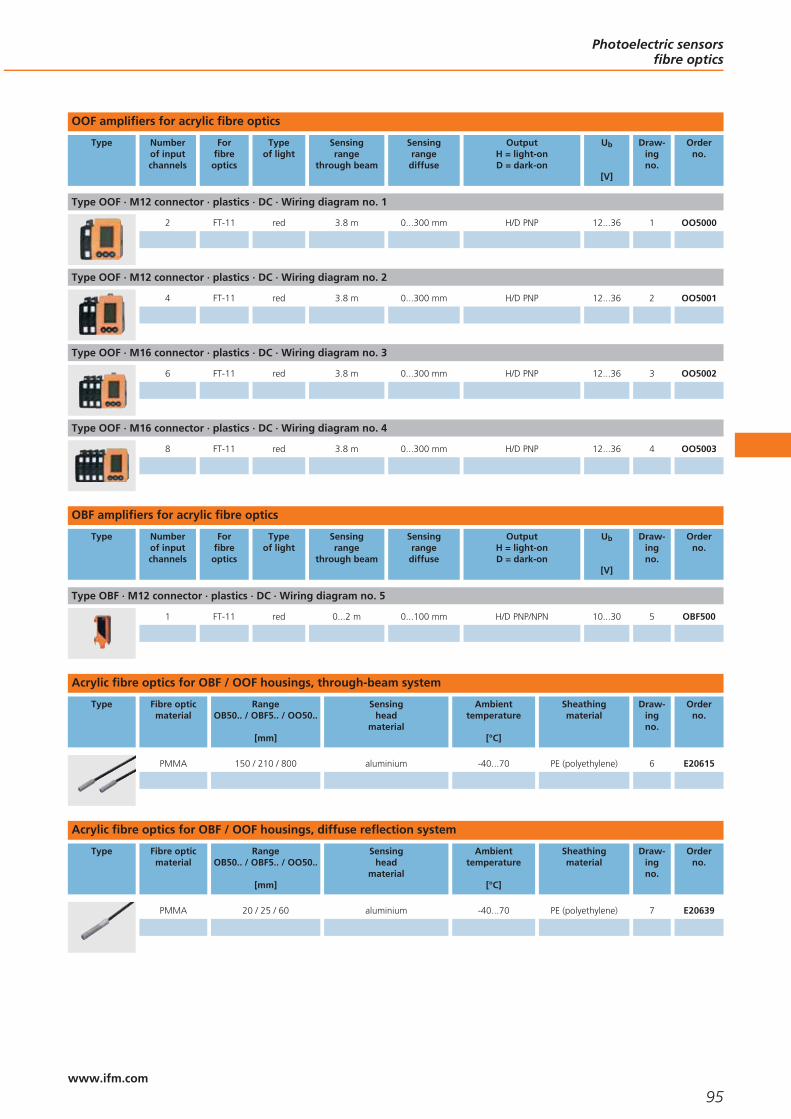
OOF amplifiers for acrylic fibre optics
Type Numberof inputchannels
Forfibreoptics
Typeof light
Sensingrange
through beam
Sensingrangediffuse
OutputH = light-onD = dark-on
Ub
[V]
Draw-ingno.
Orderno.
Type OOF · M12 connector · plastics · DC · Wiring diagram no. 1
2 FT-11 red 3.8 m 0...300 mm H/D PNP 12...36 1 OO5000
Type OOF · M12 connector · plastics · DC · Wiring diagram no. 2
4 FT-11 red 3.8 m 0...300 mm H/D PNP 12...36 2 OO5001
Type OOF · M16 connector · plastics · DC · Wiring diagram no. 3
6 FT-11 red 3.8 m 0...300 mm H/D PNP 12...36 3 OO5002
Type OOF · M16 connector · plastics · DC · Wiring diagram no. 4
8 FT-11 red 3.8 m 0...300 mm H/D PNP 12...36 4 OO5003
OBF amplifiers for acrylic fibre optics
Type Numberof inputchannels
Forfibreoptics
Typeof light
Sensingrange
through beam
Sensingrangediffuse
OutputH = light-onD = dark-on
Ub
[V]
Draw-ingno.
Orderno.
Type OBF · M12 connector · plastics · DC · Wiring diagram no. 5
1 FT-11 red 0...2 m 0...100 mm H/D PNP/NPN 10...30 5 OBF500
Acrylic fibre optics for OBF / OOF housings, through-beam system
Type Fibre opticmaterial
RangeOB50.. / OBF5.. / OO50..
[mm]
Sensinghead
material
Ambienttemperature
[°C]
Sheathingmaterial
Draw-ingno.
Orderno.
PMMA 150 / 210 / 800 aluminium -40...70 PE (polyethylene) 6 E20615
Acrylic fibre optics for OBF / OOF housings, diffuse reflection system
Type Fibre opticmaterial
RangeOB50.. / OBF5.. / OO50..
[mm]
Sensinghead
material
Ambienttemperature
[°C]
Sheathingmaterial
Draw-ingno.
Orderno.
PMMA 20 / 25 / 60 aluminium -40...70 PE (polyethylene) 7 E20639
Photoelectric sensorsfibre optics
95www.ifm.com
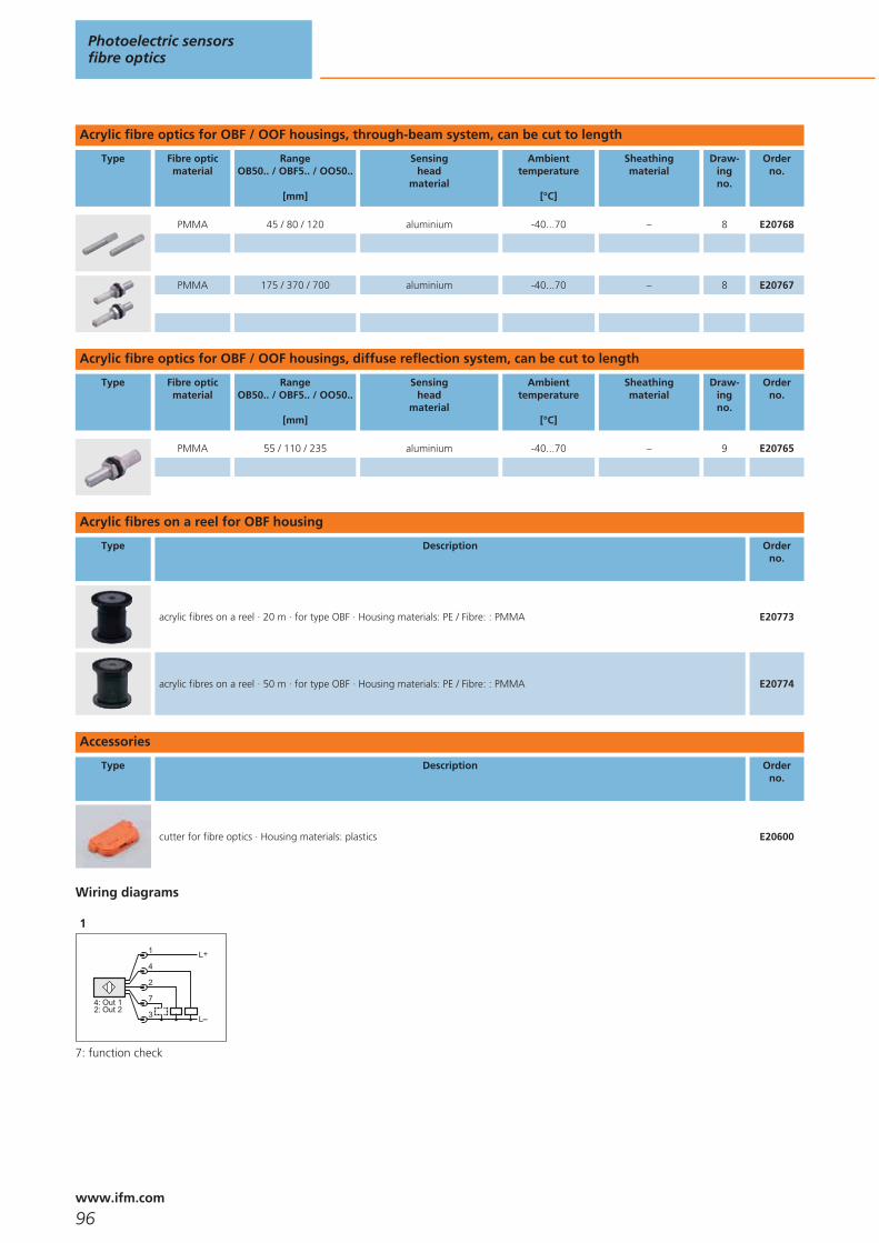
Acrylic fibre optics for OBF / OOF housings, through-beam system, can be cut to length
Type Fibre opticmaterial
RangeOB50.. / OBF5.. / OO50..
[mm]
Sensinghead
material
Ambienttemperature
[°C]
Sheathingmaterial
Draw-ingno.
Orderno.
PMMA 45 / 80 / 120 aluminium -40...70 – 8 E20768
PMMA 175 / 370 / 700 aluminium -40...70 – 8 E20767
Acrylic fibre optics for OBF / OOF housings, diffuse reflection system, can be cut to length
Type Fibre opticmaterial
RangeOB50.. / OBF5.. / OO50..
[mm]
Sensinghead
material
Ambienttemperature
[°C]
Sheathingmaterial
Draw-ingno.
Orderno.
PMMA 55 / 110 / 235 aluminium -40...70 – 9 E20765
Acrylic fibres on a reel for OBF housing
Type Description Orderno.
acrylic fibres on a reel · 20 m · for type OBF · Housing materials: PE / Fibre: : PMMA E20773
acrylic fibres on a reel · 50 m · for type OBF · Housing materials: PE / Fibre: : PMMA E20774
Accessories
Type Description Orderno.
cutter for fibre optics · Housing materials: plastics E20600
Wiring diagrams
1
L+
L
1
4
2
7
3Out 2Out 1
2:4:
7: function check
Photoelectric sensorsfibre optics
96www.ifm.com

Wiring diagrams
2
4:2:5:
Out 1Out 2Out 3
6: Out 4
L+
L
1
4
6
7
3
7: function check
3
L+
L
A
E
T
O
L
E:P:S:
Out 1Out 2Out 3
G: Out 4C:T:
Out 5Out 6
O: function check
4
E:P:S:
Out 1Out 2Out 3
G: Out 4C:T:
Out 5Out 6
N:J:
Out 7Out 8
L+
L
A
E
J
O
L
O: function check
5
2
L
L+4
1
3
4
L
L+2
1
3
Scale drawings - CAD download: www.ifm.com
1
1: mounting on DIN rail
2
1: mounting on DIN rail
Photoelectric sensorsfibre optics
97www.ifm.com

Scale drawings - CAD download: www.ifm.com
3
1: mounting on DIN rail
4
1: mounting on DIN rail
5
15
36
LED
2
M12
x1
1
74
6044
3,2
1: mounting on DIN rail, 2: setting pushbuttons
6
15
M4
7
23
M416
8
3010,5
5
M5
9
40
M89
14,5
Photoelectric sensorsfibre optics
98www.ifm.com

Photoelectric sensorsfibre optics
99

100

Photoelectric sensorsspecific systems
Selection chart Page
Sensors for the detection of transparent objects 103
Sensors for distance and level measurement 103
Sensors for colour detection 103 - 104
Safety light grids 104
Accessories 104
Evaluation units light curtains / safety light grids 104
Scale drawings - CAD download: www.ifm.com 105
Wiring diagrams 105
101www.ifm.comwww.ifm.com

High-quality photoelectric sensorsfor different applications.
Excellent price / performance ratio.
Extremely compact laser distancesensor with 10 m range.
Sensor for the detection of transpa-rent objects (PET, glass, film etc.).
Extensive range of system componentsfor easy and safe mounting.
Detection of transparent objects
Counting bottles and glasses or the reliable monitoring of film for tear can be per-formed without problem using specially designed retro-reflective sensors.
ifm offers a retro-reflective sensor with a small switching hysteresis, in particular forthe detection of transparent objects. Due to the operating principle, retro-reflectivesensors have the advantage that the light beam must pass the object to be detectedtwice. Thus the light is sufficiently weakened to detect a transparent object safely.Precise adjustment is made by means of the Teach button.
Distance measurement
The continued development of the pmd technology (Photonic Mixer Device) nowenables distance measurement to within a millimetre at high ranges using a lasersensor. The efector pmd laser sensor operates to the time-of-flight principle: A lightbeam is emitted by a transmitting element and reflected to the receiver element byan object. The measured time of flight relates to the distance from the sensor to theobject.
Traditional time-of-flight sensors use a photodiode as receiver element. Additionalelectronics is used for signal acquisition and processing.
Disadvantage: This sensor design is complex, large in size and therefore often notsuitable for industrial position sensing.
In comparison, the efector pmd sensor’s receiver element is a “System-on-Chip”design: both sensor element and electronics for signal evaluation are integrated on asingle silicon chip called a Photonic Mixer Device (PMD).
The advantage: The sensor offers a high performance in a compact, industrially com-patible housing.
“efector pmd” can be used for level measurement and positioning tasks, for exam-ple to position industrial trucks in high bay storage areas and to protect autonomousindustrial transport systems against collision.
Typical application forcontrast sensors:Counting of glassbottles.
The efector pmdprovides an analoguesignal that is propor-tional to the object-to-sensor distance.
Photoelectric sensorsspecific systems
102www.ifm.com
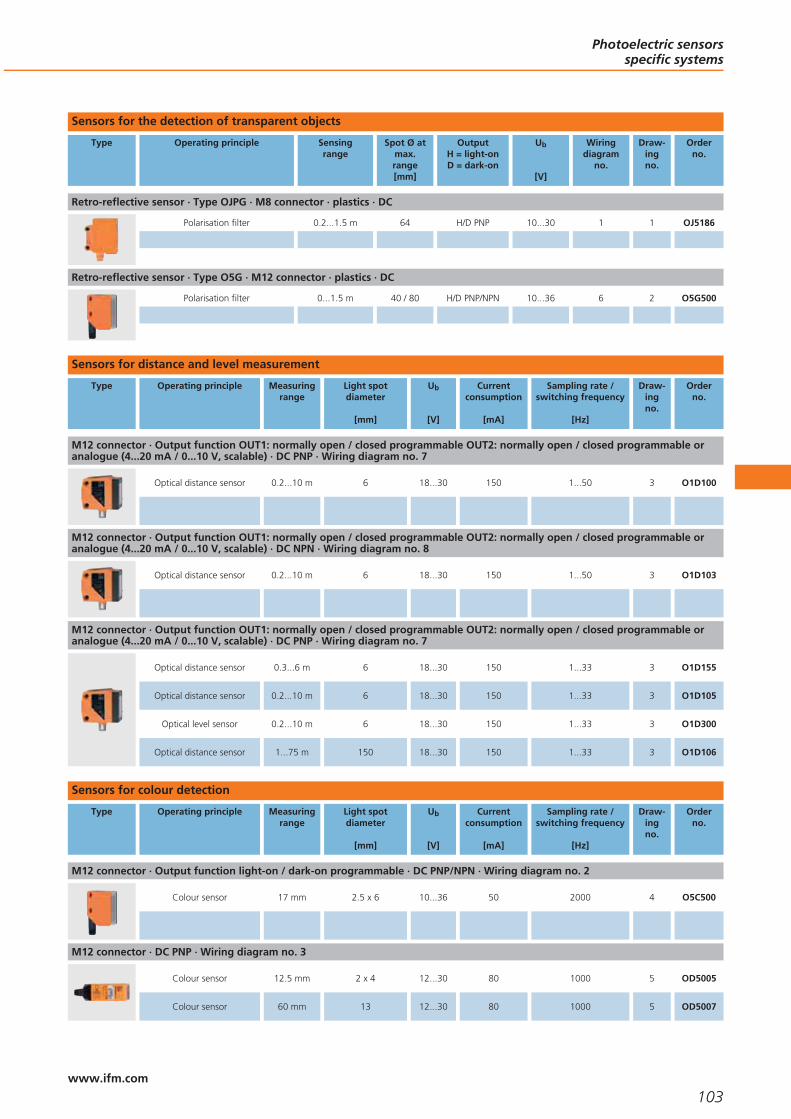
Sensors for the detection of transparent objects
Type Operating principle Sensingrange
Spot Ø atmax.range[mm]
OutputH = light-onD = dark-on
Ub
[V]
Wiringdiagram
no.
Draw-ingno.
Orderno.
Retro-reflective sensor · Type OJPG · M8 connector · plastics · DC
Polarisation filter 0.2...1.5 m 64 H/D PNP 10...30 1 1 OJ5186
Retro-reflective sensor · Type O5G · M12 connector · plastics · DC
Polarisation filter 0...1.5 m 40 / 80 H/D PNP/NPN 10...36 6 2 O5G500
Sensors for distance and level measurement
Type Operating principle Measuringrange
Light spotdiameter
[mm]
Ub
[V]
Currentconsumption
[mA]
Sampling rate /switching frequency
[Hz]
Draw-ingno.
Orderno.
M12 connector · Output function OUT1: normally open / closed programmable OUT2: normally open / closed programmable oranalogue (4...20 mA / 0...10 V, scalable) · DC PNP · Wiring diagram no. 7
Optical distance sensor 0.2...10 m 6 18...30 150 1...50 3 O1D100
M12 connector · Output function OUT1: normally open / closed programmable OUT2: normally open / closed programmable oranalogue (4...20 mA / 0...10 V, scalable) · DC NPN · Wiring diagram no. 8
Optical distance sensor 0.2...10 m 6 18...30 150 1...50 3 O1D103
M12 connector · Output function OUT1: normally open / closed programmable OUT2: normally open / closed programmable oranalogue (4...20 mA / 0...10 V, scalable) · DC PNP · Wiring diagram no. 7
Optical distance sensor 0.3...6 m 6 18...30 150 1...33 3 O1D155
Optical distance sensor 0.2...10 m 6 18...30 150 1...33 3 O1D105
Optical level sensor 0.2...10 m 6 18...30 150 1...33 3 O1D300
Optical distance sensor 1...75 m 150 18...30 150 1...33 3 O1D106
Sensors for colour detection
Type Operating principle Measuringrange
Light spotdiameter
[mm]
Ub
[V]
Currentconsumption
[mA]
Sampling rate /switching frequency
[Hz]
Draw-ingno.
Orderno.
M12 connector · Output function light-on / dark-on programmable · DC PNP/NPN · Wiring diagram no. 2
Colour sensor 17 mm 2.5 x 6 10...36 50 2000 4 O5C500
M12 connector · DC PNP · Wiring diagram no. 3
Colour sensor 12.5 mm 2 x 4 12...30 80 1000 5 OD5005
Colour sensor 60 mm 13 12...30 80 1000 5 OD5007
Photoelectric sensorsspecific systems
103www.ifm.com

Type Operating principle Measuringrange
Light spotdiameter
[mm]
Ub
[V]
Currentconsumption
[mA]
Sampling rate /switching frequency
[Hz]
Draw-ingno.
Orderno.
M12 connector · DC PNP · Wiring diagram no. 4
Colour sensor 12.5 mm 2 x 4 12...30 80 300 5 OD5009
Colour sensor 60 mm 13 12...30 80 300 5 OD5011
M12 connector · DC PNP · Wiring diagram no. 3
Colour sensor 9 mm – 12...30 80 1000 6 OD5013
Safety light grids
Type Numberof beams
Protectedarea height
[mm]
Protectedarea width
[m]
Responsetime
[ms]
Ub
[V]
Wiringdiagram
no.
Draw-ingno.
Orderno.
Complies with the requirements: type 4 , SIL 3 , SILcl 3 , PL e · M12 connector
2 510 0...10 / 3...20 2.5 24 5 7 OY120S
3 810 0...10 / 3...20 2.5 24 5 7 OY121S
4 910 0...10 / 3...20 2.5 24 5 7 OY122S
Accessories
Type Description Orderno.
Angle bracket · for type O5 · Housing materials: stainless steel 316Ti / 1.4571 E21087
Prismatic reflector · 50 x 50 mm · angular · for laser sensors and glass / film detection sensors · Housing materials: plastics E20722
Mounting set · Clamp mounting · rod mounting Ø 12 mm · for type O1D, O2D · Housing materials: fixture: stainless steel / clamp:stainless steel / screws: stainless steel / Nut: high-grade stainless steel
E2D101
Evaluation units light curtains / safety light grids
Type Description Draw-ingno.
Orderno.
Safety relay · Muting relay · Housing for DIN rail mounting · For the connection of safety light curtains / safety light gridswith OSSD · Safety category type 4 to IEC 61496 · for industrial applications
8 G2001S
Photoelectric sensorsspecific systems
104www.ifm.com
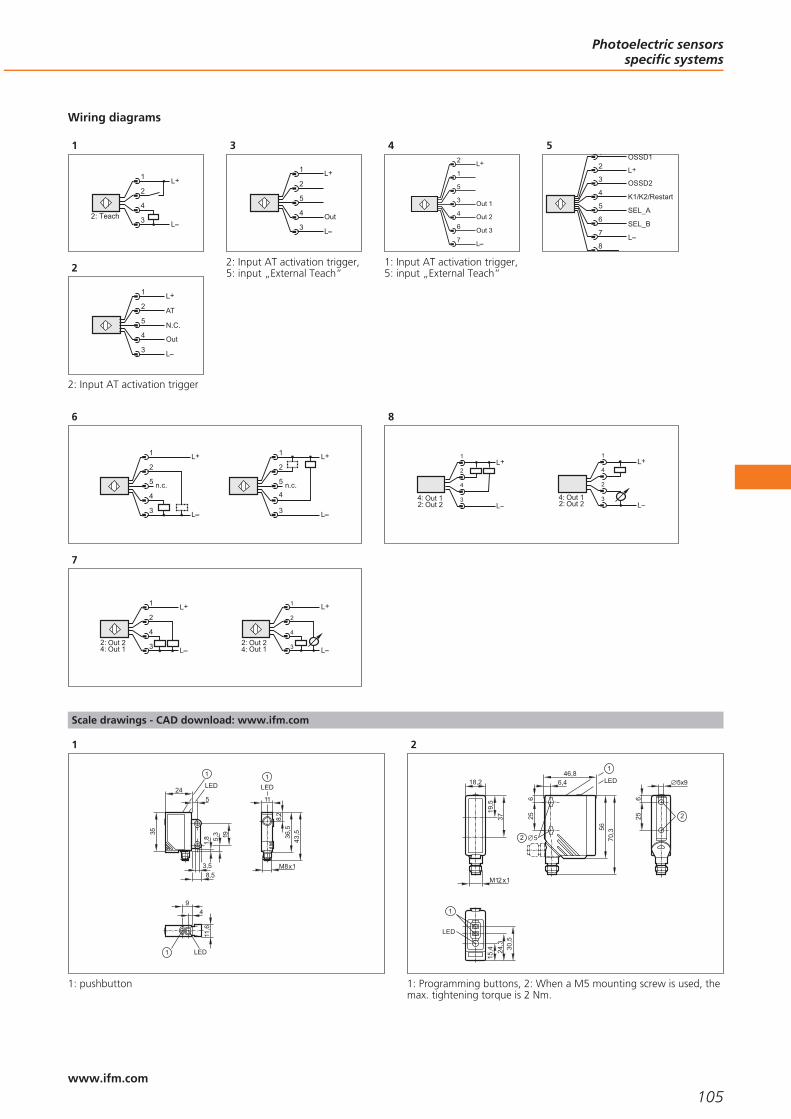
Wiring diagrams
1
L+2
4
1
3 L2: Teach
2
L+
L
2
5
1
4
3Out
N.C.
AT
2: Input AT activation trigger
3
L+
L
2
5
1
4
3Out
2: Input AT activation trigger,5: input „External Teach“
4
Out 3
5
3
1
4
6
Out 1
Out 2
L+2
L7
1: Input AT activation trigger,5: input „External Teach“
5
5
4
3
2
6
7
1 OSSD1
OSSD2
K1/K2/Restart
SEL_A
SEL_B
8
L+
L
6
L+
L
2
5
1
4
3
n.c.
L+
L
2
5
1
4
3
n.c.
7
L+
L3
4
2
1
Out 1Out 2
4:2:
4
L
L+1
2
3Out 1Out 2
4:2:
8
L
L+
Out 2Out 1
2:4: 3
4
2
1L+
LOut 2Out 1
2:4: 3
2
4
1
Scale drawings - CAD download: www.ifm.com
1
1
9
LED
4
11,6
M8x1
1
36,5
11
LED
8,2
43,5
1
24LED
35
8,5
1,8 5,
3 19
3,5
5
1: pushbutton
2
18,2
M12 x1
19,5
37
1
LED
30,5
24,3
15,4
5x9
625 2
56
6,446,8
25
70,3
5
1
LED
6
2
1: Programming buttons, 2: When a M5 mounting screw is used, themax. tightening torque is 2 Nm.
Photoelectric sensorsspecific systems
105www.ifm.com

Scale drawings - CAD download: www.ifm.com
3
52
1 2
30
45
2520
4,5
6
4559
42
M12x1
30
1: 4-digit alphanumeric display, 2: Programming buttons
4
56
6,446,8
25
70,3
5
1
LED
6
2
1
LED
30,5
24,3
15,4
5x9
625 2
18,2
M12 x1
25,9
38
1: Programming buttons, 2: When a M5 mounting screw is used, themax. tightening torque is 2 Nm.
5
4380
M12
x1
96
28
21 30
M5
M12
x1
3928
4053
69
M5
15
1
LED
LED
2
3
4
1: lens, 2: selection switch color tolerance, 3: programming selectorswitch, 4: teach button
6
4380
M12
x1
96
28
21 30
M5
119
M12
x1
3928
4053
69
M5
LED
LED
2
3
4
14
1
1: fibre optic connection, 2: selection switch color tolerance, 3: pro-gramming selector switch, 4: teach button
7
40 2010
3
1010,528
28
5,5
40
10
2010
1,5
M5
14,5
30
28
T
M12x1
5129
,510
2L
R
T: Transmitter, R: Receiver, 1: LED 3 colours (red/green/orange), 2:LED yellow, 3: LED 2 colours (red/green)
8
114,5
99
35
Photoelectric sensorsspecific systems
106www.ifm.com

Photoelectric sensorsspecific systems
107

108

Object recognition
Selection chart Page
Sensors for object recognition with PNP output function 111
Accessories 2D 111
Sensors for 3D object recognition 111
Accessories 3D 112
Scale drawings - CAD download: www.ifm.com 112
109www.ifm.comwww.ifm.com

2D vision sensor for object recognition.
3D sensor for assessment of distance, level or volume.
3D camera for spatial detection of scenes and objects.
Easy, time-saving parameter setting.
Robust, industrially compatible housing with integrated lighting.
2D vision sensor for object recognition
In automation technology visions sensors are an integral part of assembly and manu-facturing tasks as well as quality control and thus increase efficiency. They arecameras with application-specific evaluation, i.e. reliable electronic eyes at a low costand a high degree of integration. In a robust, industrially compatible housing theycombine lighting, lens, camera chip, evaluation and process connections for the inte-gration in the higher-level controller.
The application possibilities of efector dualis range from presence, position andorientation monitoring, via sorting and counting tasks to quality control.
3D sensor for assessment of distance, level or volume
efector pmd 3d is the first industrial 3D sensor that can assess objects in three dimen-sions at a glance.
Special feature: the time-of-flight measurement and evaluation are integrated onone chip. Each pixel of this chip matrix evaluates its distance to the object. The imageof the object on the chip matrix and the respective distance values correspond to a3D image.
This technology enables the detailed assessment of the object’s or scene’s conditionsby means of volume, distance or level detection in three dimensions. Typical applica-tions are completeness checks and level monitoring in the food industry as well aspresence and dimension monitoring in conveying.
3D camera for detection in three dimensions of scenes and objects
The pmd 3d camera detects scenes and objects in their spatial dimensions at aglance. In contrast to laser scanners it does not require moving components and isthus robust and wear-free. The operating principle is the same as for the 3D sensor.
Besides the 3D distance image the camera provides a grey image of the scene. Thecombination of these images offers integrators the possibility to freely programapplication-specific tasks by means of a software development kit. This results in low-cost application solutions in the areas of packaging, storage and materials handling,airport logistics, collision avoidance, robotics, monitoring of space and persons.
Set-up in just a fewsteps: The profes-sional and easy menuguidance allowsconfiguration of theefector dualis to yourapplication in just sixoperating steps.
Object recognition
110www.ifm.com

Sensors for object recognition with PNP output function
Type Operatingprinciple
Typeof light
Max.field of
view size[mm]
Detectionrate
[Hz]
Motionspeed(max.)[m/s]
Draw-ingno.
Orderno.
Type O2D2 · · metal · DC
Object recognition sensor – 640 x 480 10 1 1 O2D220
Accessories 2D
Type Description Orderno.
Operating software · O2D E2D200
Mounting set · O2D, O2M, O2I · Clamp mounting · rod mounting Ø 12 mm · Housing materials: fixture: stainless steel / clamp:stainless steel
E2D110
mounting rod · Ø 14 / M12 · Length: 130 mm · straight · Housing materials: stainless steel 316Ti / 1.4571 E20939
mounting rod · Ø 14 / M12 · Length: 200 mm · angled · Housing materials: stainless steel 316Ti / 1.4571 E20941
Cube · M12 · aluminium profile · Housing materials: diecast zinc E20952
Plastic protective pane for the food industry · O2D / O2I · Housing materials: housing: diecast zinc black / lens: PMMA E21166
Patch cable · Cross-over patch cable · Cable length 5 m E30112
Socket · ifm electronic · angled · Free from silicone · Free from halogen · gold-plated contacts · M12 connector · 5 m · Housingmaterials: PUR
E11232
Sensors for 3D object recognition
Type Operatingprinciple
Reso-lution
[pixels]
Angle of aperture(horizontal x
vertical)[°]
Lighting Max.sampling
rate[Hz]
Ub
[V]
Wiringdiagram
no.
Draw-ingno.
Orderno.
PMD 3D sensor · Type O3D · M12 connector · metal · DC
PMD 3D sensor 64 x 48 30° x 40° Infrared LED 20 24 1 2 O3D200
Object recognition
111www.ifm.com

Accessories 3D
Type Description Orderno.
Operating software for PMD 3D sensor · O3D E3D200
Mounting set · O3D · Clamp mounting · rod mounting Ø 14 mm · Housing materials: fixture: stainless steel / clamp: stainless steel E3D103
mounting rod · Ø 14 / M12 · Length: 130 mm · straight · Housing materials: stainless steel 316Ti / 1.4571 E20939
Scale drawings - CAD download: www.ifm.com
1
M12x1
2
19
M12x1
53,5
4,3
20,5
44
19,733
1
45
24,5
42
57
8060
21
9,57
3
1: display, 2: Focus setting, 3: Centre of the lens axes
2
95
60,540
4563
,8
16
75
137
120
123,
5
18M12x1
M12x1
94
21,5
1: lens, 2: Illumination unit, 3: Display / buttons / LEDs, 4: Focus set-ting
Object recognition
112www.ifm.com

Object recognition
113

114

Encoders
Selection chart Page
Incremental encoders with solid shaft 117
Incremental encoders with hollow shaft 117
Absolute multiturn encoders (Profibus) 117
Absolute singleturn - encoders (CANopen) 117
Absolute multiturn - encoders (CANopen) 118
Accessories 118
Scale drawings - CAD download: www.ifm.com 118 - 119
115www.ifm.comwww.ifm.com

Robust designs.
Industrial standard housings.
Cable entry for axial and radial use.
Designs with integrated bus interface.
Hollow shaft encoder for direct mounting on actuators.
Encoders
In many manufacturing and production processes they are indispensable as reliabletransducers to ensure precise positioning. They convert rotary movement into digitalsignals. Linear measurement is also possible in conjunction with rack and pinion ormeasuring wheels. Encoders use the wear-free photoelectric detection. A pulse discfirmly attached to the shaft ensures this detection. Encoders are basically divided intotwo types: incremental and absolute encoders.
Incremental encoders
Incremental encoders generate a precisely defined number of pulses per revolution.They are a measure of the angular or linear distance moved. The coded disc is dividedinto separate segments which are alternately transparent or opaque. An LED emits aparallel-orientated light beam which illuminates all segments of the coded disc.Photo elements receive the modulated light and convert it into two sinusoidal sig-nals. Digitalisation electronics amplify the signals and shape them into square-wavepulse trains which are generated via the line driver in the output. The phase differ-ence between signal A and B, which are phase-shifted by 90 degrees, allows evalua-tion of the direction of rotation.
Absolute encoders
Absolute encoders provide an absolute numerical value for each angular position.This code value is available immediately after power is applied. This “absolute” valuemakes a reference procedure like the one required for the incremental encoderunnecessary. Absolute encoders are used wherever angular positions have to beallocated to a certain value and where the detection of the present position is abso-lutely necessary in the case of a power failure.
Singleturn and multiturn
Singleturn encoders divide a mechanical revolution (0 to 360 degrees) into a certainnumber of measuring steps. The measuring values are repeated after one revolution.The maximum resolution is 8192.
Multiturn encoders, however, do not only detect angular positions but also distin-guish between multiple revolutions.
Linear measurementby means of a count-er: rotary movementis converted intodigital signals.
Hollow shaft encoderfor direct mounting
on the axis.
Encoders
116www.ifm.com

Incremental encoders with solid shaft
Type Resolution Ub
[V]
f
[kHz]
Iload
[mA]
Shaft
[mm]
Ambienttemperature
[°C]
Cableentry
Draw-ingno.
Orderno.
Cable 2 m · Output TTL output 20 mA
500 5 300 20 6 -30...100 radial / axially 1 RB1015
Cable 2 m · Output HTL-output 50 mA, short-circuit protected < 1 min
125 10...30 160 50 6 -30...70 radial / axially 1 RB6009
500 10...30 160 50 6 -30...70 radial / axially 1 RB6015
1000 10...30 160 50 6 -30...70 radial / axially 1 RB6029
Cable 2 m · Output TTL output 20 mA
500 5 300 20 6 -40...100 radial / axially 2 RU1016
1024 5 300 20 6 -40...100 radial / axially 2 RU1025
Incremental encoders with hollow shaft
Type Resolution Ub
[V]
f
[kHz]
Iload
[mA]
Shaft
[mm]
Ambienttemperature
[°C]
Cableentry
Draw-ingno.
Orderno.
Cable 1 m · Output HTL-output 50 mA, short-circuit protected < 1 min
500 10...30 300 50 12 H7 -40...100 radial / axially 3 RO6344
1024 10...30 300 50 12 H7 -40...100 radial / axially 3 RO6345
Absolute multiturn encoders (Profibus)
Type Resolution Ub
[V]
f
[kHz]
Iload
[mA]
Shaft
[mm]
Ambienttemperature
[°C]
Cableentry
Draw-ingno.
Orderno.
Terminals · Output Profibus data interface
25 bits 10...30 – – 10 -40...70 – 4 RM3005
Absolute singleturn - encoders (CANopen)
Type Resolution Ub
[V]
f
[kHz]
Iload
[mA]
Shaft
[mm]
Ambienttemperature
[°C]
Cableentry
Draw-ingno.
Orderno.
Terminals · Output CANopen interface
13 bits 9...36 – – 6 -40...70 – 5 RN7003
13 bits 9...36 – – 10 -40...70 – 4 RN7004
Encoders
117www.ifm.com

Absolute multiturn - encoders (CANopen)
Type Resolution Ub
[V]
f
[kHz]
Iload
[mA]
Shaft
[mm]
Ambienttemperature
[°C]
Cableentry
Draw-ingno.
Orderno.
Terminals · Output CANopen interface
25 bits 9...36 – – 6 -40...70 – 5 RM7003
25 bits 9...36 – – 10 -40...70 – 4 RM7004
Accessories
Type Description Orderno.
Angle bracket · for encoders · for type RB, RC, RU, RN, RM · Housing materials: aluminium black anodised E60033
Angle bracket · for encoders · for type RM, RMU, RN, RU · Housing materials: aluminium black anodised E60034
Flexible coupling with clamp connection [KV] · Ø 6 mm / Ø 6 mm · Housing materials: aluminium E60064
Flexible coupling with adjusting screw connection [SV] · Ø 6 mm / Ø 6 mm · Housing materials: aluminium E60063
Flexible coupling with adjusting screw connection [SV] · Ø 6 mm / Ø 10 mm · Housing materials: aluminium E60028
Scale drawings - CAD download: www.ifm.com
1
251
237,5
618 35
215
30°
4,5
1: reference mark, 2: M3 5 mm deep
2
4
3
650 58
3
10
h7
46,7±0,5
6
120°
421 2
1: reference mark, 2: M4 5 mm deep
Encoders
118www.ifm.com

Scale drawings - CAD download: www.ifm.com
3
2063 68
3,2
6
34,5
12H
724
28
47,2±0,5
58
TX 8
4
120°
48
20°
24
1
70
18
1036 58
20
f8
10
1: M4 5 mm deep
5
120°
42
20°
24
1
80
18
4
3
650 58
3
10,5
h7
1: M4 5 mm deep
Encoders
119www.ifm.com

120
Evaluation systems
Selection chart Page
Universal speed monitors 123
Speed monitor with integrated sensor 123
Multifunctional displays for digital signals / frequency input 123
Universal counters 123
Multifunctional displays for analogue standard signals 124
Accessories 124
Scale drawings - CAD download: www.ifm.com 124
Wiring diagrams 124
121www.ifm.comwww.ifm.com

Easy adjustment and parameter setting.
Clear LCD display with simplepushbutton setup.
Primary voltage 24V dc or 110 / 230V ac.
Switching relays and transistor outputs.Analogue also available.
Standstill, overspeed, direction, slipand frequency conversion.
Evaluation systems
Although PLC applications in industrial automation are becoming more and moreversatile there are still numerous processes in practice which require decentralisedmonitoring.
For this ifm electronic offers a number of pulse evaluation systems in the productgroup “ecomat 200”. The application area ranges from simple standstill monitoringor blockage protection of a conveyor belt, maximum speed monitoring in windpower stations, slip monitoring of couplings through to direction monitoring, e.g.twin pumps with non-return valves.
Different units for rail mounting and compact designs in M18 and M30 metalhousings are available. They include microprocessor-controlled units for panemounting to display analogue signals, RPM, speeds, processing times, quantities andelectronic preset counters for the detection of quantities or linear measurement aswell as electronic timer relays.
All units are distinguished by a high reliability and easy handling. Independent of thePLC they indicate operating states or signal faults. This helps to reduce downtimesand production loss.
ifm electronic offers the following evaluation systems:
Speed monitor
Standstill monitor
Slip- / synchronisation monitor
Direction monitor
Frequency-to-current converter
Threshold relay
Displays with frequency and analogue input
Counters
Switching amplifiers
Pulse evaluationsystems are used fordecentralised moni-toring of drives.
Machine cycles mustalso be monitored in
conveying.
Evaluation systems
122www.ifm.com
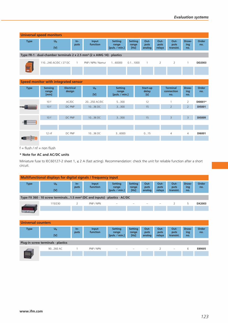
Universal speed monitors
Type Ub
[V]
In-puts
Inputfunction
Settingrange
[puls. / min.]
Settingrange[Hz]
Out-puts
analog
Out-puts
relays
Out-puts
transist.
Draw-ingno.
Orderno.
Type FR-1 · dual-chamber terminals 2 x 2.5 mm² (2 x AWG 14) · plastics
110...240 AC/DC / 27 DC 1 PNP / NPN / Namur 1...60000 0.1...1000 1 2 2 1 DD2003
Speed monitor with integrated sensor
Type Sensingrange[mm]
Electricaldesign
Ub
[V]
Settingrange
[puls. / min.]
Start-updelay
[s]
Terminalconnection
no.
Draw-ingno.
Orderno.
10 f AC/DC 20...250 AC/DC 5...300 12 1 2 DI0001*
10 f DC PNP 10...36 DC 3...300 15 2 2 DI5001
10 f DC PNP 10...36 DC 3...300 15 3 3 DI5009
12 nf DC PNP 10...36 DC 3...6000 0...15 4 4 DI6001
f = flush / nf = non flush
* Note for AC and AC/DC units
Miniature fuse to IEC60127-2 sheet 1, ≤ 2 A (fast acting). Recommendation: check the unit for reliable function after a shortcircuit.
Multifunctional displays for digital signals / frequency input
Type Ub
[V]
In-puts
Inputfunction
Settingrange
[puls. / min.]
Settingrange[Hz]
Out-puts
analog
Out-puts
relays
Out-puts
transist.
Draw-ingno.
Orderno.
Type FX 360 · 10 screw terminals...1.5 mm² (DC and inputs) · plastics · AC/DC
115/230 2 PNP / NPN – – – – 2 5 DX2003
Universal counters
Type Ub
[V]
In-puts
Inputfunction
Settingrange
[puls. / min.]
Settingrange[Hz]
Out-puts
analog
Out-puts
relays
Out-puts
transist.
Draw-ingno.
Orderno.
Plug-in screw terminals · plastics
90...260 AC 1 PNP / NPN – – – 2 – 6 E89005
Evaluation systems
123www.ifm.com

Multifunctional displays for analogue standard signals
Type Ub
[V]
In-puts
Inputfunction
Settingrange
[puls. / min.]
Settingrange[Hz]
Out-puts
analog
Out-puts
relays
Out-puts
transist.
Draw-ingno.
Orderno.
terminals up to 2.5 mm² · plastics
– 1 4...20 mA – – 1 2 2 7 E89150
Accessories
Type Description Orderno.
Angle bracket · for type M18 · Housing materials: stainless steel E10736
Angle bracket · for type M30 · Housing materials: stainless steel E10737
Wiring diagrams
1
BN
BU
L+L1
LN
2
BN
BK
BU
L+
L
3
L+
L
1
4
3
4
4
L
L+1
2
3
2: pulse output (the pulsesequence corresponds to thedamping frequency), 4: swit-ching output (adjustable)
Scale drawings - CAD download: www.ifm.com
1
45
78
1 4 652
19 20 21 22 23 24
13 14 15 16 17 18
3
97A1 8A2 10 11 12
120
35,5
1
1: mounting on DIN rail
2
36
8167
58
5
M30
x1,5
9
18
2 LED
pot. 61
3
36
8266
59
5LED
M30
x1,5
M12
x1
92
pot.
4
M12
x1
77
5640
M18
x1
68
10
42421
1: 3 LED, 2: setting pushbutton
Evaluation systems
124www.ifm.com

Scale drawings - CAD download: www.ifm.com
5
96
48
129 9
6
48105
86,5 3
45
7
75
39
50 4
33
control panel cutout: 68 x 33 mm (according to DIN)
Evaluation systems
125www.ifm.com

126

Level sensors
Selection chart Page
Sensors for oils and coolants, LK12xx: approval to the German overspill standard WHG,section 19 129
Variable level sensors for water-based media (dielectric constant > 20) 129
Sensors for hydrostatic level monitoring 129 - 130
Sensors for hydrostatic level monitoring in hygienic and wet areas 130
Sensors for oils and coolants, LI20xx: approval to the German overspill standard WHG,section 19 131
Accessories for level sensors LK, LR, LT, LL, LI 131
Accessories for level sensors PA, PG, PI, PN, PS, PY 132
Scale drawings - CAD download: www.ifm.com 133
Wiring diagrams 133
127www.ifm.comwww.ifm.com

Guided wave radar, capacitive andhydrostatic level sensors.
No movings parts means highreliability and long life.
Outputs for continuous or discretelevel measurement.
Integrated LED display for localindication of the current level.
Units suitable for common industrialand process fluids.
Level sensors
In industrial applications where fluids or bulk material are used, storage tanks or silosare used for processing or storing of media. Sensors are used to detect the levels.Even critical process conditions such as emptying a hydraulic tank or the uninten-tional overspill of a tank are monitored by level sensors.
Advantages of electronic sensors
Deposits and wear and tear often lead to failures in particular if mechanical switchesare in contact with the medium. The electronic ifm sensors however can do withoutany mechanical components. This makes the sensors especially robust and reliable.
Another advantage of electronic sensors is the local indication of the level or the easysetting of the switching threshold simply by pressing a button.
Measurement technique
For continuous level measurement the level is detected continuously, converted intoan electrical signal and indicated. Depending on the type the units have freely pro-grammable switching outputs or an analogue output for further processing.
Continuous level sensors from ifm electronic use three different physical measuringprinciples:
For capacitive measurement the probe and the tank form an electrical capacitor. Thecapacity changes with the level and is converted into a level measurement by amicroprocessor.
For hydrostatic level measurement a measuring cell detects the hydrostatic pressureof the material. Here the pressure change is a measure for the level.
The efector gwr level sensor operates on the principle of guided wave radar. Electro-magnetic pulses are transmitted by the sensor head and guided along the probe. Ifthe microwave pulse hits the medium to be detected, it is reflected and the time offlight is evaluated by the sensor.
Measurement inthe medium:Probe sensors willdirectly immersed inthe medium to bemonitored.
For special applica-tions: Capacitive
probe for monitoringoils and coolants.
Level sensors
128www.ifm.com

Sensors for oils and coolants, LK12xx: approval to the German overspill standard WHG, section 19
Type Probelength[mm]
Activezone[mm]
Inactive zone[mm]
Ub
[V]
Mediumtemperature
[°C]
Iload
[mA]
Wiringdiagram
no.
Draw-ingno.
Orderno.
M12 connector (according to EN 61076-2-101) · Output function 1 x analogue 4...20 mA / 0...10 V (OUT2); 1 x normally open / clo-sed programmable (OUT-OP) · DC PNP
264 195 53 / 15 18...30 – 200 1 1 LK3122
472 390 53 / 30 18...30 – 200 1 1 LK3123
728 585 102 / 40 18...30 – 200 1 1 LK3124
M12 connector (according to EN 61076-2-101) · Output function 2 x normally open / closed programmable · DC PNP
264 195 53 / 15 18...30 – 200 2 1 LK1022
472 390 53 / 30 18...30 – 200 2 1 LK1023
728 585 102 / 40 18...30 – 200 2 1 LK1024
M12 connector (according to EN 61076-2-101) · Output function 3 x normally open / closed programmable (OUT1...OUT3); 1 x nor-mally open / closed programmabl (OUT-OP) · DC PNP
264 195 53 / 15 18...30 – 200 3 1 LK8122
472 390 53 / 30 18...30 – 200 3 1 LK8123
728 585 102 / 40 18...30 – 200 3 1 LK8124
Variable level sensors for water-based media (dielectric constant > 20)
Type Probelength[mm]
Activezone[mm]
Inactive zone[mm]
Ub
[V]
Mediumtemperature
[°C]
Iload
[mA]
Wiringdiagram
no.
Draw-ingno.
Orderno.
M12 connector (according to EN 61076-2-101) · Output function normally open / closed programmable; 4...20 mA or 0...10 V · DCPNP
150...1600 L - 50 40/10 18...30 0...80 200 4 2 LR3000
M12 connector (according to EN 61076-2-101) · Output function 2 x normally open / closed programmable · DC PNP
150...1600 L - 50 40/10 18...30 0...80 200 2 2 LR7000
M12 connector (according to EN 61076-2-101) · Output function 4 x normally open / closed programmable · DC PNP
150...1600 L - 50 40/10 18...30 0...80 200 5 3 LR8000
Sensors for hydrostatic level monitoring
Type Processconnection
Display
LED
Measuringrange[bar]
Poverload
max. [bar]
Pbursting
min. [bar]
UbDC[V]
Wiringdiagram
no.
Draw-ingno.
Orderno.
M12 connector · Output function 1 x normally open / closed programmable + 1 x analogue (I / U, scaleable 1:4) · DC PNP/NPN
G¼ I Display unit -0.25...0.25 10 30 18...32 9 4 PY2068
M12 connector · Output function 2 x normally open / closed programmable or 1 x normally open / closed programmable + 1 xanalogue (4...20 mA / 0...10 V; scaleable 1:4) · DC PNP/NPN
G¼ I Display unit -0.5...0.5 10 30 20...30 10 5 PN2069
Level sensors
129www.ifm.com
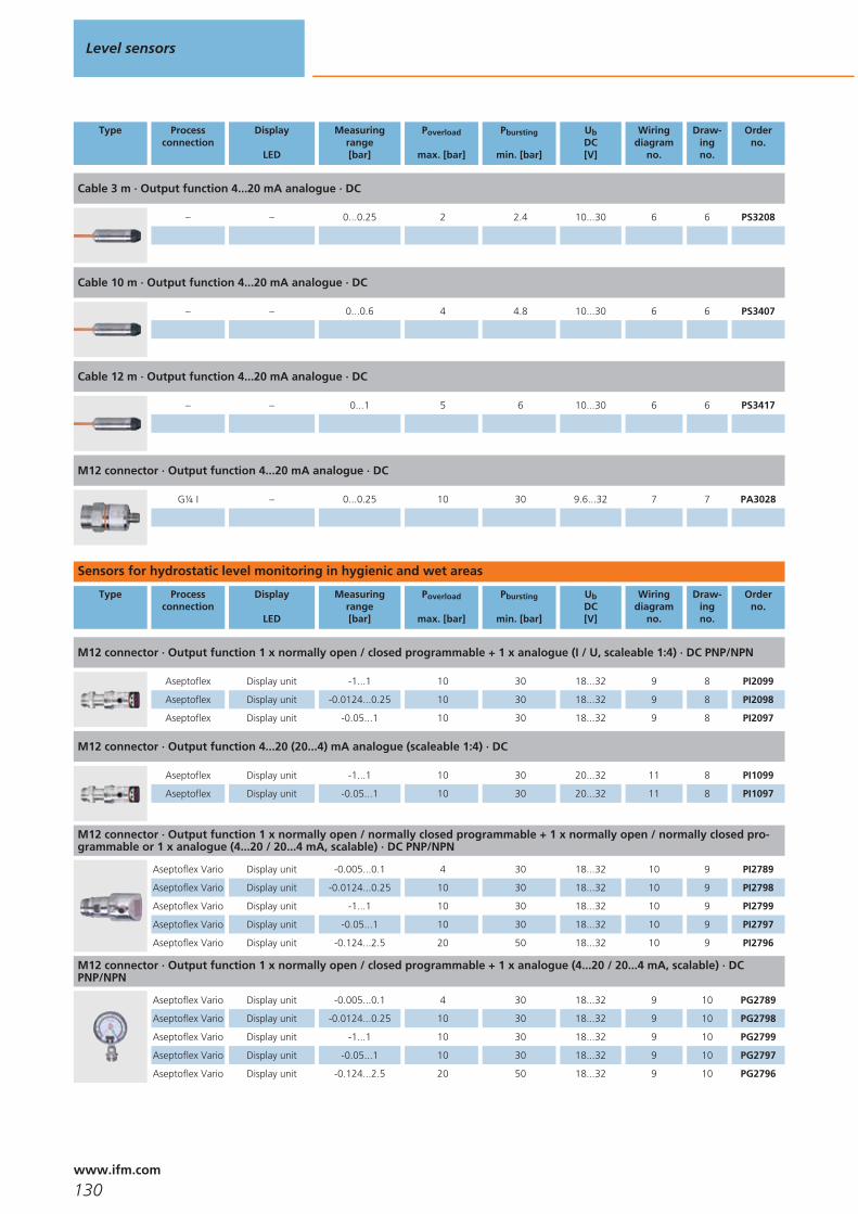
Type Processconnection
Display
LED
Measuringrange[bar]
Poverload
max. [bar]
Pbursting
min. [bar]
UbDC[V]
Wiringdiagram
no.
Draw-ingno.
Orderno.
Cable 3 m · Output function 4...20 mA analogue · DC
– – 0...0.25 2 2.4 10...30 6 6 PS3208
Cable 10 m · Output function 4...20 mA analogue · DC
– – 0...0.6 4 4.8 10...30 6 6 PS3407
Cable 12 m · Output function 4...20 mA analogue · DC
– – 0...1 5 6 10...30 6 6 PS3417
M12 connector · Output function 4...20 mA analogue · DC
G¼ I – 0...0.25 10 30 9.6...32 7 7 PA3028
Sensors for hydrostatic level monitoring in hygienic and wet areas
Type Processconnection
Display
LED
Measuringrange[bar]
Poverload
max. [bar]
Pbursting
min. [bar]
UbDC[V]
Wiringdiagram
no.
Draw-ingno.
Orderno.
M12 connector · Output function 1 x normally open / closed programmable + 1 x analogue (I / U, scaleable 1:4) · DC PNP/NPN
Aseptoflex Display unit -1...1 10 30 18...32 9 8 PI2099
Aseptoflex Display unit -0.0124...0.25 10 30 18...32 9 8 PI2098
Aseptoflex Display unit -0.05...1 10 30 18...32 9 8 PI2097
M12 connector · Output function 4...20 (20...4) mA analogue (scaleable 1:4) · DC
Aseptoflex Display unit -1...1 10 30 20...32 11 8 PI1099
Aseptoflex Display unit -0.05...1 10 30 20...32 11 8 PI1097
M12 connector · Output function 1 x normally open / normally closed programmable + 1 x normally open / normally closed pro-grammable or 1 x analogue (4...20 / 20...4 mA, scalable) · DC PNP/NPN
Aseptoflex Vario Display unit -0.005...0.1 4 30 18...32 10 9 PI2789
Aseptoflex Vario Display unit -0.0124...0.25 10 30 18...32 10 9 PI2798
Aseptoflex Vario Display unit -1...1 10 30 18...32 10 9 PI2799
Aseptoflex Vario Display unit -0.05...1 10 30 18...32 10 9 PI2797
Aseptoflex Vario Display unit -0.124...2.5 20 50 18...32 10 9 PI2796
M12 connector · Output function 1 x normally open / closed programmable + 1 x analogue (4...20 / 20...4 mA, scalable) · DCPNP/NPN
Aseptoflex Vario Display unit -0.005...0.1 4 30 18...32 9 10 PG2789
Aseptoflex Vario Display unit -0.0124...0.25 10 30 18...32 9 10 PG2798
Aseptoflex Vario Display unit -1...1 10 30 18...32 9 10 PG2799
Aseptoflex Vario Display unit -0.05...1 10 30 18...32 9 10 PG2797
Aseptoflex Vario Display unit -0.124...2.5 20 50 18...32 9 10 PG2796
Level sensors
130www.ifm.com
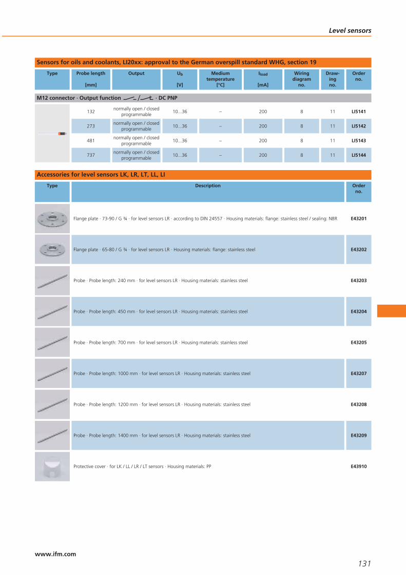
Sensors for oils and coolants, LI20xx: approval to the German overspill standard WHG, section 19
Type Probe length
[mm]
Output Ub
[V]
Mediumtemperature
[°C]
Iload
[mA]
Wiringdiagram
no.
Draw-ingno.
Orderno.
M12 connector · Output function · DC PNP
132normally open / closed
programmable10...36 – 200 8 11 LI5141
273normally open / closed
programmable10...36 – 200 8 11 LI5142
481normally open / closed
programmable10...36 – 200 8 11 LI5143
737normally open / closed
programmable10...36 – 200 8 11 LI5144
Accessories for level sensors LK, LR, LT, LL, LI
Type Description Orderno.
Flange plate · 73-90 / G ¾ · for level sensors LR · according to DIN 24557 · Housing materials: flange: stainless steel / sealing: NBR E43201
Flange plate · 65-80 / G ¾ · for level sensors LR · Housing materials: flange: stainless steel E43202
Probe · Probe length: 240 mm · for level sensors LR · Housing materials: stainless steel E43203
Probe · Probe length: 450 mm · for level sensors LR · Housing materials: stainless steel E43204
Probe · Probe length: 700 mm · for level sensors LR · Housing materials: stainless steel E43205
Probe · Probe length: 1000 mm · for level sensors LR · Housing materials: stainless steel E43207
Probe · Probe length: 1200 mm · for level sensors LR · Housing materials: stainless steel E43208
Probe · Probe length: 1400 mm · for level sensors LR · Housing materials: stainless steel E43209
Protective cover · for LK / LL / LR / LT sensors · Housing materials: PP E43910
Level sensors
131www.ifm.com

Accessories for level sensors PA, PG, PI, PN, PS, PY
Type Description Orderno.
Protective cover · for fluid sensors with connector M12 · Housing materials: polyurethane E30006
Protective cover · for fluid sensors · stainless steel with transparent Teflon window · Housing materials: stainless steel 316Ti / 1.4571/ PFA / EPDM / ventilation strip: Teflon film 0.32 mm / O-ring: EPDM
E30104
Adapter · G ¼ - G ¼ · Housing materials: stainless steel / FPM E30007
Cable clamp fastener · for submersible pressure transmitter PS3 · Housing materials: steel / plastics E30399
Filter element · for submersible pressure transmitter PS3 · for fixing on the capillary tube E30400
Splitter box · with ventilation and terminal block · for submersible pressure transmitter PS3 · Housing materials: plastics E30401
Additional weight · for submersible pressure transmitter PS3 · Housing materials: stainless steel 316Ti / 1.4571 E30402
Welding adapter · Ø 50 mm · with Aseptoflex thread · Housing materials: stainless steel 316L / 1.4404 / O-ring: FPM FDA compliant E30052
Aseptoflex adapter · Clamp · 1-1.5“ · ISO 2852 · for units with Aseptoflex adapter · Housing materials: stainless steel 316L / 1.4404 E33001
Welding adapter · Ø 50 mm · for units with Aseptoflex Vario adapter · Sealing by sealing ring · Housing materials: stainless steel316L / 1.4435
E30122
Aseptoflex Vario adapter · Clamp · 1-1.5“ · ISO 2852 · for units with Aseptoflex Vario adapter · Sealing by sealing ring · Housingmaterials: stainless steel 316L / 1.4435
E33201
Aseptoflex Vario adapter · Clamp · 1-1.5“ · ISO 2852 · for units with Aseptoflex Vario adapter · Metal to metal seal · Housingmaterials: stainless steel 316L / 1.4435
E33701
Level sensors
132www.ifm.com

Wiring diagrams
1
L+
L3 BU
4 BK
2 WH
1 BN
Out-OPOut 2
4:2:
2
2
L
L+4
1
3Out 1Out 2
4:2:
3
Out-OP / Out 4
3
4
2
5
6
Out 1
Out 3
L+1
n.c.7
Out 2
L
4
L+
LOUT1OUT2
4:2:
4
2
1
3
5
L+
Ln.c.Out 4
Out 1Out 2
124
673
Out 35
6
BN
GY
WHL+
L
7
L+
L
1
2
8
L+
L
1
4
3
9
4
1
3
2L+
L
2
1
3
4L+
L
10
4
L
L+2
1
3Out 1Out 2
4:2:
4
L
L+2
1
3Out 1Out 2
4:2:
4
1
3
2L+
LOut 1Out 2
4:2:
2
1
3
4L+
LOut 1Out 2
4:2:
11
4
1
3
2L+
L
L
P
2
L+
L
1
2
1
1: Normal operation, 2: Programming operation (P = communi-cation via EPS / FDT interface)
Scale drawings - CAD download: www.ifm.com
1
30,5
64
M12
x1
4 3I1L
16
50
57A
I2
32
1
1: 4-digit alphanumeric display, 2: LEDs, 3: Programming buttons, 4:Housing connection (flat-pin connector 6.3 mm following DIN 46244)
Level sensors
133www.ifm.com

Scale drawings - CAD download: www.ifm.com
2
I1
L
50
57A
I2
32
1
7687
30
63
M12
x1G 43
8 6
32
1: 4-digit alphanumeric display, 2: LEDs (display unit / switching sta-tus), 3: Programming buttons
3
30
63
M12
x1
G 43
8 6
32
I1
L
50
57A
I2
32
1
7687
1: 4-digit alphanumeric display, 2: LEDs (display unit / switching sta-tus), 3: Programming buttons
4
91,5
34
27
1,3
21,5
2 3
1
30
48
57,3
G
M12
x1
14
1 4/
1: 4-digit alphanumeric display, 2: LEDs (display unit / switching sta-tus), 3: Programming button
5
91,5
34
27
1,3
21,5
2 3
1
30
47
57,3
G
M12
x1
14
1 4/
1: 4-digit alphanumeric display, 2: LEDs (display unit / switching sta-tus), 3: Programming button
6
100
27
7
75
M12 x130
30
27
1,3
21,5
14
G 41
8
119
34
14,5
2 3
36
1
48
36
47
85M
12x1
4 5
1: 4-digit alphanumeric display, 2: LEDs, 3: Programming button, 4:Aseptoflex sealing edge, 5: Aseptoflex thread
Level sensors
134www.ifm.com
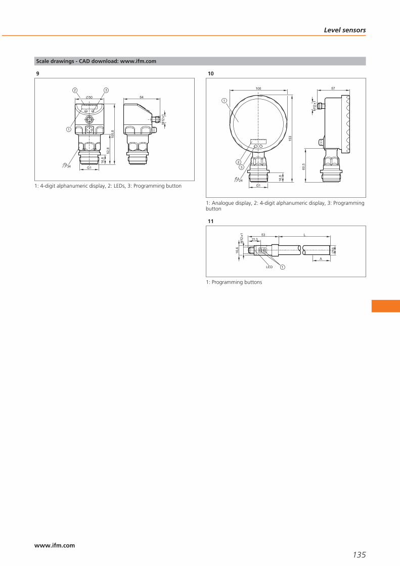
Scale drawings - CAD download: www.ifm.com
9
16,8
G1
64
M12
x1
105,
852
,8
50
34
1
2 3
1: 4-digit alphanumeric display, 2: LEDs, 3: Programming button
10
24
3
153
16,8
100
2
1
57
60,5
M12
x1
G1
1: Analogue display, 2: 4-digit alphanumeric display, 3: Programmingbutton
11
L
16
53
M12
x1
LED
21,3
1
16,6
A
1: Programming buttons
Level sensors
135www.ifm.com

136

Flow sensors
Selection chart Page
Magnetic-inductive flow sensors with integrated temperature measurement (sealingmaterial EPDM) 139
Magnetic-inductive flow sensors (sealing material FKM) 139
Compact housings for adapters for flow monitoring 139
Compact designs for adapter with flow and temperature monitoring 140
Compact housings for adapters for hygienic and wet areas 140
Flow sensors for connection to control monitors, industrial applications 140
Flow sensors for connection to control monitors, industrial applications, titanium housing 140
Control monitors for industrial applications 141
Flow sensors for connection to control monitors with ATEX approval 141
Control monitors with ATEX approval 142
Air flow monitors 142
Compressed air meters 142
Compressed air meter for special gases 143
Inline sensor for small dosing quantities of water and aqueous solutions 143
Ultrasonic flow rate sensors for liquids (water, glycol solutions, oils) 143
Accessories for flow sensors and control monitors 143 - 144
Flange adapters for flow sensors 144 - 145
Accessories for volumetric flow sensors 145
Grounding clamps for magnetic-inductive volumetric flow sensors 145
Wiring diagrams 145 - 146
Scale drawings - CAD download: www.ifm.com 146 - 150
137www.ifm.comwww.ifm.com

For liquids and gases.
Special versions for food applications and hazardous areas.
Optional fittings for variable process connection.
Flow monitoring also for aggressive media.
Flow sensors
In almost all fields of process and plant engineering liquids or gases are used forcoolant and lubricant supply of machines and units, ventilation of installations andbuildings and the processing of products. In case of no flow of these media consid-erable damage and downtime may result. Thus it is very important to monitor thatthese media are at the right place at the right time and in sufficient quantities. Inmodern installations electronic flow monitors are used for this purpose. They workwithout wear and tear and without mechanical components. This guarantees reliablemonitoring even in case of difficult media over a long period.
Operating principle
Electronic flow sensors from ifm electronic operate with different measurement tech-niques.
They meet all requirements from a simple monitoring function to the exact detectionof flow quantities.
Harmonised operating menus ensure that operators who use different flow sensorscan quickly and precisely carry out settings on the sensors.
Some flow sensors feature an integrated temperature monitor which makes anadditional measuring point unnecessary. This enables to control processes in theoptimum operating status especially with regard to energy savings.
Analogue, binary and pulse outputs offer various possibilities to process the mea-sured data. Due to the flexible programming by means of pushbuttons the flow sen-sors can be adapted to different conditions. The sensors are mounted via adapters.
Monitoring very smallflow rates: Flow moni-tor with flow adapter.
Optimisedconsumption ofcompressed air.
Flow sensors
138www.ifm.com
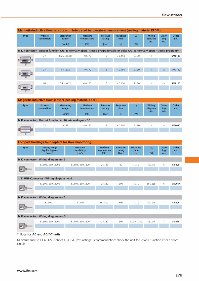
Magnetic-inductive flow sensors with integrated temperature measurement (sealing material EPDM)
Type Processconnection
Measuringrange
[l/min]
Mediumtemperature
[°C]
Pressurerating
[bar]
Responsetime
[s]
Ub
[V]
Wiringdiagram
no.
Draw-ingno.
Orderno.
M12 connector · Output function OUT1: normally open / closed programmable or pulse OUT2: normally open / closed programm-
G½ 0.25...25.00 -10...70 16 < 0.150 19...30 1 1 SM6100
G¾ 0.5...50.0 -10...70 16 < 0.150 19...30 1 2 SM7100
G1 0.7...100.0 -10...70 16 < 0.150 19...30 1 3 SM8100
Magnetic-inductive flow sensors (sealing material FKM)
Type Processconnection
Measuringrange
[l/min]
Mediumtemperature
[°C]
Pressurerating
[bar]
Responsetime
[s]
Ub
[V]
Wiringdiagram
no.
Draw-ingno.
Orderno.
M12 connector · Output function 4...20 mA analogue · DC
G½ 0...25 -10...70 16 < 0.150 19...30 2 4 SM6050
Compact housings for adapters for flow monitoring
Type Setting rangeliquids / gases
[cm/s]
Greatestsensitivity
[cm/s]
Mediumtemperature
[°C]
Pressurerating[bar]
Responsetime[s]
Ub
[V]
Draw-ingno.
Orderno.
M12 connector · Wiring diagram no. 3
3...300 / 200...3000 3...100 / 200...800 -25...80 30 1...10 19...36 5 SI5000
1/2“ UNF-Connector · Wiring diagram no. 4
3...300 / 200...3000 3...100 / 200...800 -25...80 300 1...10 85...265 6 SI5006*
M12 connector · Wiring diagram no. 2
3...300 / - 3...100 -25...80 / - 300 1...10 19...36 7 SI5004
M12 connector · Wiring diagram no. 5
3...300 / 200...3000 3...100 / 200...800 -25...80 300 1...2 / 1...10 19...36 7 SI5010
* Note for AC and AC/DC units
Miniature fuse to IEC60127-2 sheet 1, ≤ 5 A (fast acting). Recommendation: check the unit for reliable function after a shortcircuit.
Flow sensors
139www.ifm.com
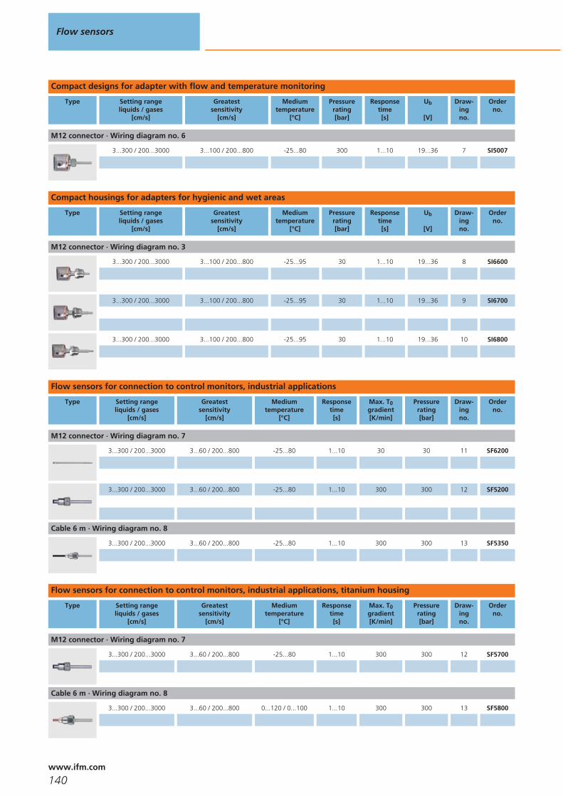
Compact designs for adapter with flow and temperature monitoring
Type Setting rangeliquids / gases
[cm/s]
Greatestsensitivity
[cm/s]
Mediumtemperature
[°C]
Pressurerating[bar]
Responsetime[s]
Ub
[V]
Draw-ingno.
Orderno.
M12 connector · Wiring diagram no. 6
3...300 / 200...3000 3...100 / 200...800 -25...80 300 1...10 19...36 7 SI5007
Compact housings for adapters for hygienic and wet areas
Type Setting rangeliquids / gases
[cm/s]
Greatestsensitivity
[cm/s]
Mediumtemperature
[°C]
Pressurerating[bar]
Responsetime[s]
Ub
[V]
Draw-ingno.
Orderno.
M12 connector · Wiring diagram no. 3
3...300 / 200...3000 3...100 / 200...800 -25...95 30 1...10 19...36 8 SI6600
3...300 / 200...3000 3...100 / 200...800 -25...95 30 1...10 19...36 9 SI6700
3...300 / 200...3000 3...100 / 200...800 -25...95 30 1...10 19...36 10 SI6800
Flow sensors for connection to control monitors, industrial applications
Type Setting rangeliquids / gases
[cm/s]
Greatestsensitivity
[cm/s]
Mediumtemperature
[°C]
Responsetime[s]
Max. T0gradient[K/min]
Pressurerating[bar]
Draw-ingno.
Orderno.
M12 connector · Wiring diagram no. 7
3...300 / 200...3000 3...60 / 200...800 -25...80 1...10 30 30 11 SF6200
3...300 / 200...3000 3...60 / 200...800 -25...80 1...10 300 300 12 SF5200
Cable 6 m · Wiring diagram no. 8
3...300 / 200...3000 3...60 / 200...800 -25...80 1...10 300 300 13 SF5350
Flow sensors for connection to control monitors, industrial applications, titanium housing
Type Setting rangeliquids / gases
[cm/s]
Greatestsensitivity
[cm/s]
Mediumtemperature
[°C]
Responsetime[s]
Max. T0gradient[K/min]
Pressurerating[bar]
Draw-ingno.
Orderno.
M12 connector · Wiring diagram no. 7
3...300 / 200...3000 3...60 / 200...800 -25...80 1...10 300 300 12 SF5700
Cable 6 m · Wiring diagram no. 8
3...300 / 200...3000 3...60 / 200...800 0...120 / 0...100 1...10 300 300 13 SF5800
Flow sensors
140www.ifm.com

Control monitors for industrial applications
Type Ub / Tolerance
[V] / [%]
Currentconsumpt.
[mA]
Powerconsumpt.
[VA]
Power-ondelay time
[s]
Outputwhen flow is
present
Outputwhen temp. is exceeded
Outputin case of
wire break
Draw-ingno.
Orderno.
Combicon connector · Wiring diagram no. 13
/ -5 /+10 – 4 10...80 relay energised relay energised relay de-energised 14 SN0150*
Combicon connector · Wiring diagram no. 14
24 DC / +10 / -20
90 – 10...80 relay energised relay energised relay de-energised 14 SR0150*
M12 connector · Wiring diagram no. 3
19...36 DC 70 – 10no / nc
programmable– – 15 SR5900
1/2“ UNF-Connector · Wiring diagram no. 4
85...265 AC / -5/ +10
– < 3.5 10no / nc
programmable– – 16 SR5906*
* Note for AC and AC/DC units
Miniature fuse to IEC60127-2 sheet 1, Note: miniature fuse to IEC60127-2 sheet 1,. Recommendation: check the unit for relia-ble function after a short circuit.
Flow sensors for connection to control monitors with ATEX approval
Type Setting rangeliquids / gases
[cm/s]
Greatestsensitivity
[cm/s]
Mediumtemperature
[°C]
Responsetime[s]
Max. T0gradient[K/min]
Pressurerating[bar]
Draw-ingno.
Orderno.
Cable 6 m · Wiring diagram no. 9
3...300 / 200...2000 3...60 / 200...800 -20...60 1...10 15 300 17 SF211A
3...300 / 200...2000 3...60 / 200...800 -20...70 1...10 15 30 18 SF221A
3...300 / 200...2000 3...60 / 200...800 -20...70 1...10 15 30 19 SF321A
M12 connector · Wiring diagram no. 10
3...300 / 200...2000 3...60 / 200...800 -20...70 1...10 15 30 20 SF320A
Flow sensors
141www.ifm.com
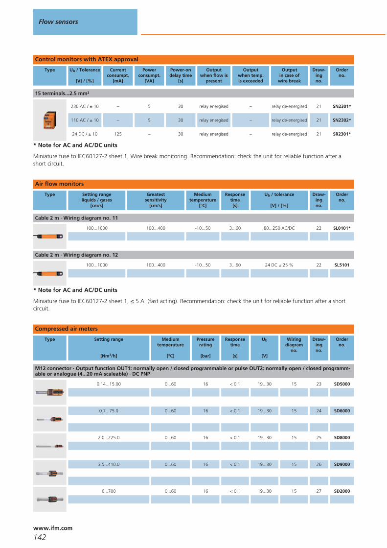
Control monitors with ATEX approval
Type Ub / Tolerance
[V] / [%]
Currentconsumpt.
[mA]
Powerconsumpt.
[VA]
Power-ondelay time
[s]
Outputwhen flow is
present
Outputwhen temp. is exceeded
Outputin case of
wire break
Draw-ingno.
Orderno.
15 terminals...2.5 mm²
230 AC / ± 10 – 5 30 relay energised – relay de-energised 21 SN2301*
110 AC / ± 10 – 5 30 relay energised – relay de-energised 21 SN2302*
24 DC / ± 10 125 – 30 relay energised – relay de-energised 21 SR2301*
* Note for AC and AC/DC units
Miniature fuse to IEC60127-2 sheet 1, Wire break monitoring. Recommendation: check the unit for reliable function after ashort circuit.
Air flow monitors
Type Setting rangeliquids / gases
[cm/s]
Greatestsensitivity
[cm/s]
Mediumtemperature
[°C]
Responsetime[s]
Ub / tolerance
[V] / [%]
Draw-ingno.
Orderno.
Cable 2 m · Wiring diagram no. 11
100...1000 100...400 -10...50 3...60 80...250 AC/DC 22 SL0101*
Cable 2 m · Wiring diagram no. 12
100...1000 100...400 -10...50 3...60 24 DC ± 25 % 22 SL5101
* Note for AC and AC/DC units
Miniature fuse to IEC60127-2 sheet 1, ≤ 5 A (fast acting). Recommendation: check the unit for reliable function after a shortcircuit.
Compressed air meters
Type Setting range
[Nm3/h]
Mediumtemperature
[°C]
Pressurerating
[bar]
Responsetime
[s]
Ub
[V]
Wiringdiagram
no.
Draw-ingno.
Orderno.
M12 connector · Output function OUT1: normally open / closed programmable or pulse OUT2: normally open / closed programm-able or analogue (4...20 mA scaleable) · DC PNP
0.14...15.00 0...60 16 < 0.1 19...30 15 23 SD5000
0.7...75.0 0...60 16 < 0.1 19...30 15 24 SD6000
2.0...225.0 0...60 16 < 0.1 19...30 15 25 SD8000
3.5...410.0 0...60 16 < 0.1 19...30 15 26 SD9000
6...700 0...60 16 < 0.1 19...30 15 27 SD2000
Flow sensors
142www.ifm.com

Compressed air meter for special gases
Type Setting range
[Nm3/h]
Mediumtemperature
[°C]
Pressurerating
[bar]
Responsetime
[s]
Ub
[V]
Wiringdiagram
no.
Draw-ingno.
Orderno.
M12 connector · Output function OUT1: normally open / closed programmable or pulse OUT2: normally open / closed programm-able or analogue (4...20 mA scaleable) · DC PNP
Ar: 0.8...118.2 / CO2: 0.5...71.7 / N2:0.5...73.0 Nm³/h
0...60 16 < 0.1 19...30 15 24 SD6100
Inline sensor for small dosing quantities of water and aqueous solutions
Type Processconnection
Measuring range
[ml/min]
Display range
[ml/min]
Pressurerating[bar]
Mediumtemp.[°C]
Draw-ingno.
Orderno.
M12 connector · Wiring diagram no. 15
G1/8 1...200 0...240 10 0...60 28 SQ0500
Ultrasonic flow rate sensors for liquids (water, glycol solutions, oils)
Type Processconnection
Measuringrange
[l/min]
Mediumtemperature
[°C]
Pressurerating
[bar]
Responsetime
[s]
Ub
[V]
Wiringdiagram
no.
Draw-ingno.
Orderno.
M12 connector · Output function OUT1: normally open / closed programmable or pulse OUT2: normally open / closed programm-able or analogue (4...20 mA / 0...10 V, scaleable) · DC PNP/NPN
G¾ 0.1...50.0 -10...80 16 < 0.250 19...30 1 29 SU7000
G1 0.2...100.0 -10...80 16 < 0.250 19...30 1 30 SU8000
G1¼ 0.4...200.0 -10...80 16 < 0.250 19...30 1 31 SU9000
Accessories for flow sensors and control monitors
Type Description Orderno.
Adapter · M18 x 1.5 - G ½ · Insertion depth of the probe of SID, SFD, TN: · 21 mm · Housing materials: titanium E40114
Adapter · M18 x 1.5 - G ¼ · Insertion depth of the probe of SID, SFD, TN: · 13.5 mm · Housing materials: titanium E40115
Adapter · M18 x 1.5 - M12 x 1 · Insertion depth of the probe of SID, SFD, TN: · 13.5 mm · Housing materials: titanium E40128
Flow sensors
143www.ifm.com

Type Description Orderno.
Adapter · M18 x 1.5 - M12 x 1 · Insertion depth of the probe of SID, SFD, TN: · 13.5 mm · Housing materials: stainless steel 316L /1.4404
E40101
Adapter · M18 x 1.5 - G ¼ · Insertion depth of the probe of SID, SFD, TN: · 13.5 mm · Housing materials: stainless steel 316L /1.4404
E40099
Adapter · M18 x 1.5 - G ½ · Insertion depth of the probe of SID, SFD, TN: · 21 mm · Housing materials: stainless steel 316L / 1.4404 E40096
Welding adapter · M18 x 1.5 - Ø 23 mm · Insertion depth of the probe of SID, SFD, TN: · 21 mm · Housing materials: PE-100 E40138
Welding adapter · M18 x 1.5 - Ø 24 mm · Insertion depth of the probe of SID, SFD, TN: · 15 mm · Housing materials: stainless steel316L / 1.4404
E40124
Flow adapter (for low flow rates) · M12 x 1 - G 1/8 · for flow sensors and compact flow monitors with adapter · Housing materials:stainless steel 316L / 1.4404
E40129
Flow adapter (for low flow rates) · G ¼ - G 1/8 · for flow sensors and compact flow monitors · ¼“ · Housing materials: PVDF E40057
Flange adapters for flow sensors
Type Description Orderno.
Aseptoflex Vario adapter · Clamp · 1-1.5“ · ISO 2852 · for units with Aseptoflex Vario adapter · Sealing by sealing ring · Housingmaterials: stainless steel 316L / 1.4435
E33201
Aseptoflex Vario adapter · Clamp · 2“ · ISO 2852 · for units with Aseptoflex Vario adapter · Sealing by sealing ring · Housingmaterials: stainless steel 316L / 1.4435
E33202
Aseptoflex Vario adapter · Clamp · 1-1.5“ · ISO 2852 · for units with Aseptoflex Vario adapter · Metal to metal seal · Housingmaterials: stainless steel 316L / 1.4435
E33701
Aseptoflex Vario adapter · Clamp · 2“ · ISO 2852 · for units with Aseptoflex Vario adapter · Metal to metal seal · Housing materials:stainless steel 316L / 1.4435
E33702
Aseptoflex Vario adapter · Varivent type N · DN40 (1.5“), D = 68 · for units with Aseptoflex Vario adapter · Sealing by sealing ring ·Housing materials: stainless steel 316L / 1.4435
E33222
Aseptoflex Vario adapter · Varivent type F · DN25 (1“), D = 50 · for units with Aseptoflex Vario adapter · Metal to metal seal ·Housing materials: stainless steel 316L / 1.4435
E33721
Flow sensors
144www.ifm.com

Type Description Orderno.
Aseptoflex Vario adapter · Varivent type N · DN40 (1.5“), D = 68 · for units with Aseptoflex Vario adapter · Metal to metal seal ·Housing materials: stainless steel 316L / 1.4435
E33722
Welding adapter · Ø 50 mm · for units with Aseptoflex Vario adapter · Sealing by sealing ring · Housing materials: stainless steel316L / 1.4435
E30122
Accessories for volumetric flow sensors
Type Description Orderno.
Adapter · G ½ - R ½ · for flow monitor type SM6 · flat seal · Housing materials: stainless steel 316Ti / 1.4571 · Pack quantity: 2 E40199
Adapter · G ½ - G ¾ · for flow monitor type SM6 · flat seal · Housing materials: high-grade stainless steel E40189
Grounding clamps for magnetic-inductive volumetric flow sensors
Type Description Orderno.
Grounding clamp G½ · for flow monitor type SM6 · Housing materials: stainless steel E40196
Wiring diagrams
1
4
1
3
2 OUT2/InD
L+
L
BN
BUOUT1
WH
BK
2
L+
L3
2
4
1
n.c.
n.c. = not connected
3
L+
L
1
4
3
4
1
3
4
2
5
n.c.
L1
N
Out
5
P
L+1
4
3
2L
P = programming wire (forremote adjustment)
6
L
L+
3
2
4
1
S2 S1
7
2 WH
1 BN
4 BK
3 BU
5 GY
8
BU
BK
BN
WH
GY
9
BN
WH
BK
BU
123
789
GY
VS2000 Exi
10
123
789
VS2000 Exi
1 BN
2 WH
4 BK
3 BU
5 GY
11
BN
WH
BU
BK
L1
N
L+
L
12
BN
WH
BU
BKL+
L
Flow sensors
145www.ifm.com

Wiring diagrams
13
ACLN
12
11
10
9
8
7
6
5
421
19
18
17
5
4
1
3
2
GY
BK
BN
BU
WH
20
21
22
23
24
1
2
35
4
1: Flow monitoring, 2: Wire break monitoring, 3: Temperaturemonitoring, 4: Power-on delay time, 5: Selection liquid / gas
14
12
11
10
9
8
7
6
5
421
19
18
17
5
4
1
3
2
GY
BK
BN
BU
WH
20
21
22
23
24
1
2
35
4
DCL+L
1: Flow monitoring, 2: Wire break monitoring, 3: Temperaturemonitoring, 4: Power-on delay time, 5: Selection liquid / gas
15
L+
LOut 2Out 1
2:4: 3
4
2
1
L
L+
Out 2Out 1
2:4: 3
4
2
1
Scale drawings - CAD download: www.ifm.com
1
11073
M12 x1
16
G G2
1
21
M12 x1
54
2
G4
3
G4
3
11073
M12 x1
19
M12 x1
54
3
G1
G1
11073
M12 x1
19
M12 x1
54
4
11073
M12 x1
16
G G2
1
21
M12 x1
54
5
22
1 2
113
60 65
14
7,7
45
50
27
63
M12
x1
1: LED display, 2: setting pushbutton
Flow sensors
146www.ifm.com

Scale drawings - CAD download: www.ifm.com
6
22
1 2
113
60 65
14
8,2
4550
27
63
" 20U
NF
2A2
1
1: LED display, 2: setting pushbutton
7
22
1 2
113
60 65
14
8,2
45
50
27
63
M12
x1
1: LED display, 2: setting pushbutton
8
M12
x1
34
7,7
50
2071
119
27
63
1: LED display, 2: setting pushbutton, 3: G1/Aseptoflex Vario thread
9
M12
x1
34
7,710,8
50
3815
8913
7
27
63
1: LED display, 2: setting pushbutton, 3: G1/Aseptoflex Vario thread
10
M12
x1
34
7,710,8
50
5515
106
154
27
63
1: LED display, 2: setting pushbutton, 3: G1/Aseptoflex Vario thread
11
7,745
15
M12
x1
217
10
2025 146
12
M12
x1
8272
22
14
8,2
44
19 1
1: internal thread M18 x 1.5
Flow sensors
147www.ifm.com
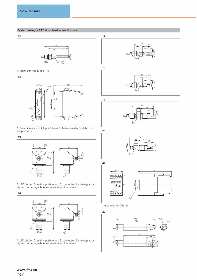
Scale drawings - CAD download: www.ifm.com
13
8672
22
14
8,2
44
19 1
1: internal thread M18 x 1.5
14
103,5
35,5
25
100
2
1
LEDs
LEDs
1 2 3 4
5 6 7 8
9 10 11 12
21 22 23 24
17 18 19 20
1: Potentiometer (switch point flow), 2: Potentiometer (switch pointtemperature)
15
27
64
M12
x1
4
1 2
835248
50
19,7
3
1: LED display, 2: setting pushbutton, 3: connection for voltage sup-ply and output signals, 4: connection for flow sensor
16
27
64
4
1 2
835248
50
19,7
3
" 20U
NF
2A2
1
1: LED display, 2: setting pushbutton, 3: connection for voltage sup-ply and output signals, 4: connection for flow sensor
17
17
57
122713
8,2
G4
1
18
17
57
122713
7,7G
41
19
124515
80
27
G2
1
7,7
20
M12
x1
124515
75
7,727
G2
1
21
45
78
1 2
19 20 21
13 14 15 16 17 18
3
97 8
+
120
35,5
1
1: mounting on DIN rail
22
140133
11332
23
2 LED
pot.2 LED
Flow sensors
148www.ifm.com
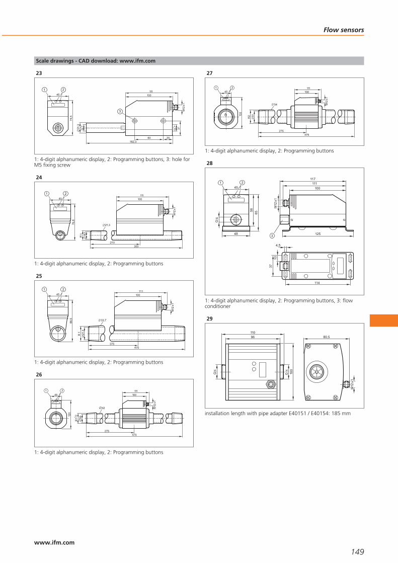
Scale drawings - CAD download: www.ifm.com
23
182,3
21,3
M12
x1
100111
74,5
G1
4 /
45
1 2
G1
4 /
60 20
31
3
1: 4-digit alphanumeric display, 2: Programming buttons, 3: hole forM5 fixing screw
24
R
210300
16,1
21,3
M12
x1
100111
76,8
45
1 2
1: 4-digit alphanumeric display, 2: Programming buttons
25
475375
27,3
33,7
R 1
M12
x1
100111
88,5
45
1 2
1: 4-digit alphanumeric display, 2: Programming buttons
26
39R
112
275475
42
100111
M12
x1
120
451 2
1: 4-digit alphanumeric display, 2: Programming buttons
27
133
451 2
54
R2 51
100111
M12
x1
275475
1: 4-digit alphanumeric display, 2: Programming buttons
28
114
4,5
3710
M12
x1
100
125
111117
56
45
G8
1
48
65
1: 4-digit alphanumeric display, 2: Programming buttons, 3: flowconditioner
29
G4
3
G4
3
11096
100
80,5
M12
x1
installation length with pipe adapter E40151 / E40154: 185 mm
Flow sensors
149www.ifm.com

Scale drawings - CAD download: www.ifm.com
30
80,5
M12
x1
G1
13096
100
G1
installation length with pipe adapter E40152 / E40155: 205 mm,installation length with pipe adapter E40153 / E40156: 215 mm
31
80,5
M12
x1
26
48
13096
100
G1
41
G1
41
Flow sensors
150www.ifm.com

Flow sensors
151

152

Pressure sensors
Selection chart Page
Sensors with switching outputs and analogue outputs and display 155
Sensors with switching outputs and display 155
PK sensors with mechanical setting and switching outputs 155
PT sensors for mobile applications with analogue outputs 156
PA / PPA sensors for industrial applications with analogue outputs / AS-i 156
Sensors for hydrostatic level monitoring 156
PI sensors for hygienic and wet areas, 2-wire with analogue output 157
PI sensors for hygienic and wet areas with switching and analogue output 157
Full-metal sensors for hygienic and wet areas with switching output and analogue output 157
Electronic contact manometers for hygienic and wet areas with switching output and ana-logue output 158
Sensors for pump monitoring 158
PF sensors for hygienic and wet areas with switching and analogue output 158
PL / PM sensors without display for hygienic and wet areas with analogue output 159
Sensors for hygienic and wet areas with Profibus PA Interface 159
Fixing components for pressure sensors 159
Accessories and software 159 - 160
Adapters and accessories for adapters 160
Flange adapters 160 - 161
Wiring diagrams 161 - 162
Scale drawings - CAD download: www.ifm.com 162 - 164
153www.ifm.comwww.ifm.com

Transmitters or sensors with integrated control monitor.
Units with special design for hygienic applications.
Measuring principles with overload protection and a good long-term stability.
Measuring range from -1…600 bar.
Variable process connection and sealing technology via adapter.
Pressure sensors
ifm offers a wide range of electronic pressure and vacuum sensors to meet the re-quirements of various industrial applications. The ceramic-capacitive measuring cell,tried and tested a million times, is complemented by a stainless steel measuring cellwith thick-film wire strain gauges (series PK, PV, PT) and a piezoresistive measuringtechnique (for pneumatic applications).
All units have robust housings and do not require moving parts such as pistons orsprings. The result: the sensors are extremely shock and vibration resistant and ope-rate without any wear or maintenance.
The tried and tested ceramic-capacitive measuring principle is corrosion-resistant andlong-term stable. In the long run this guarantees continuous accuracy of the mea-sured values. The sensors are resistant to dynamic pressure peaks and guarantee highoverload resistance even in the case of extreme pressure peaks that occur for exam-ple with fast closing valves.
Units with wire strain gauge in thick-film technology on a stainless steel measuringcell are distinguished by their very compact and robust design. They can be used inalmost all industrial areas. The welded stainless steel measuring cell without any sealsensures a high degree of safety, in particular for applications with gas pressures ofup to 400 bar as well as in air-conditioning and refrigerating technology whereaggressive coolants (freons) are used.
The display: The7-segment displayshows the systempressure at a glance.
Separate display /programming unit
PP2001.
Pressure sensors
154www.ifm.com
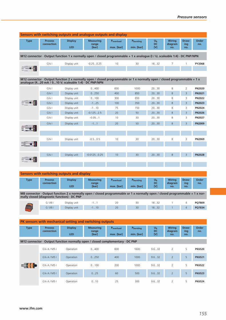
Sensors with switching outputs and analogue outputs and display
Type Processconnection
Display
LED
Measuringrange[bar]
Poverload
max. [bar]
Pbursting
min. [bar]
UbDC[V]
Wiringdiagram
no.
Draw-ingno.
Orderno.
M12 connector · Output function 1 x normally open / closed programmable + 1 x analogue (I / U, scaleable 1:4) · DC PNP/NPN
G¼ I Display unit -0.25...0.25 10 30 18...32 7 1 PY2068
M12 connector · Output function 2 x normally open / closed programmable or 1 x normally open / closed programmable + 1 xanalogue (4...20 mA / 0...10 V; scaleable 1:4) · DC PNP/NPN
G¼ I Display unit 0...400 600 1000 20...30 8 2 PN2020
G¼ I Display unit 0...250 400 850 20...30 8 3 PN2021
G¼ I Display unit 0...100 300 650 20...30 8 3 PN2022
G¼ I Display unit -1...25 100 350 20...30 8 3 PN2023
G¼ I Display unit -1...10 75 150 20...30 8 3 PN2024
G¼ I Display unit -0.125...2.5 20 50 20...30 8 3 PN2026
G¼ I Display unit -0.05...1 10 30 20...30 8 3 PN2027
G¼ I Display unit -1...1 20 50 20...30 8 3 PN2009
G¼ I Display unit -0.5...0.5 10 30 20...30 8 3 PN2069
G¼ I Display unit -0.0125...0.25 10 30 20...30 8 3 PN2028
Sensors with switching outputs and display
Type Processconnection
Display
LED
Measuringrange[bar]
Poverload
max. [bar]
Pbursting
min. [bar]
UbDC[V]
Wiringdiagram
no.
Draw-ingno.
Orderno.
M8 connector · Output function 2 x normally open / closed programmable or 1 x normally open / closed programmable + 1 x nor-mally closed (diagnostic function) · DC PNP
G 1/8 I Display unit -1...1 20 30 18...32 1 4 PQ7809
G 1/8 I Display unit -1...10 20 30 18...32 1 4 PQ7834
PK sensors with mechanical setting and switching outputs
Type Processconnection
Display
LED
Measuringrange[bar]
Poverload
max. [bar]
Pbursting
min. [bar]
UbDC[V]
Wiringdiagram
no.
Draw-ingno.
Orderno.
M12 connector · Output function normally open / closed complementary · DC PNP
G¼ A / M5 I Operation 0...400 600 1600 9.6...32 2 5 PK6520
G¼ A / M5 I Operation 0...250 400 1000 9.6...32 2 5 PK6521
G¼ A / M5 I Operation 0...100 200 1000 9.6...32 2 5 PK6522
G¼ A / M5 I Operation 0...25 60 500 9.6...32 2 5 PK6523
G¼ A / M5 I Operation 0...10 25 300 9.6...32 2 5 PK6524
Pressure sensors
155www.ifm.com

PT sensors for mobile applications with analogue outputs
Type Processconnection
Display
LED
Measuringrange[bar]
Poverload
max. [bar]
Pbursting
min. [bar]
UbDC[V]
Wiringdiagram
no.
Draw-ingno.
Orderno.
M12 connector · Output function 4...20 mA analogue · DC
G¼ A – 0...400 600 1600 8.5...32 3 6 PT3550
G¼ A – 0...250 400 1000 8.5...32 3 6 PT3551
G¼ A – 0...100 200 1000 8.5...32 3 6 PT3552
G¼ A – 0...25 60 600 8.5...32 3 6 PT3553
G¼ A – 0...10 25 300 8.5...32 3 6 PT3554
M12 connector · Output function 0...10 V analogue · DC
G¼ A – 0...400 600 1600 16...32 4 6 PT9550
G¼ A – 0...250 400 1000 16...32 4 6 PT9551
G¼ A – 0...100 200 1000 16...32 4 6 PT9552
G¼ A – 0...25 60 600 16...32 4 6 PT9553
G¼ A – 0...10 25 300 16...32 4 6 PT9554
PA / PPA sensors for industrial applications with analogue outputs / AS-i
Type Processconnection
Display
LED
Measuringrange[bar]
Poverload
max. [bar]
Pbursting
min. [bar]
UbDC[V]
Wiringdiagram
no.
Draw-ingno.
Orderno.
M12 connector · Output function 4...20 mA analogue · DC
G¼ I – 0...600 800 1200 9.6...32 3 7 PA3060
G¼ I – 0...400 600 1000 9.6...32 3 7 PA3020
G¼ I – 0...250 400 850 9.6...32 3 8 PA3021
G¼ I – 0...100 300 650 9.6...32 3 8 PA3022
G¼ I – 0...25 150 350 9.6...32 3 8 PA3023
G¼ I – 0...10 75 150 9.6...32 3 8 PA3024
G¼ I – 0...2.5 20 50 9.6...32 3 8 PA3026
G¼ I – 0...1 10 30 9.6...32 3 8 PA3027
G¼ I – 0...0.25 10 30 9.6...32 3 8 PA3028
G¼ I – -1...0 10 30 9.6...32 3 8 PA3029
Sensors for hydrostatic level monitoring
Type Measuringrange[bar]
Cable length /material
Poverload
max. [bar]
Pbursting
min. [bar]
UbDC[V]
Wiringdiagram
no.
Draw-ingno.
Orderno.
Output 4...20 mA analogue · Wiring diagram no. 5
0...0.253 m
PUR cable2 2.4 10...30 5 9 PS3208
0...0.610 m
PUR cable4 4.8 10...30 5 9 PS3407
0...112 m
PUR cable5 6 10...30 5 9 PS3417
Pressure sensors
156www.ifm.com

PI sensors for hygienic and wet areas, 2-wire with analogue output
Type Processconnection
Display
LED
Measuringrange[bar]
Poverload
max. [bar]
Pbursting
min. [bar]
UbDC[V]
Wiringdiagram
no.
Draw-ingno.
Orderno.
M12 connector · Output function 4...20 (20...4) mA analogue (scaleable 1:4) · DC
Aseptoflex Display unit -1...25 100 350 20...32 9 10 PI1093
Aseptoflex Display unit -1...10 50 150 20...32 9 10 PI1094
Aseptoflex Display unit -1...4 30 100 20...32 9 10 PI1095
Aseptoflex Display unit -0.124...2.5 20 50 20...32 9 10 PI1096
Aseptoflex Display unit -0.05...1 10 30 20...32 9 10 PI1097
Aseptoflex Display unit -1...1 10 30 20...32 9 10 PI1099
G1 A Display unit -1...25 100 350 20...32 9 11 PI1693
G1 A Display unit -1...10 50 150 20...32 9 11 PI1694
G1 A Display unit -1...4 30 100 20...32 9 11 PI1695
G1 A Display unit -0.124...2.5 20 50 20...32 9 11 PI1696
G1 A Display unit -0.05...1 10 30 20...32 9 11 PI1697
G1 A Display unit -0.0124...0.25 10 30 20...32 9 11 PI1698
G1 A Display unit -1...1 10 30 20...32 9 11 PI1699
PI sensors for hygienic and wet areas with switching and analogue output
Type Processconnection
Display
LED
Measuringrange[bar]
Poverload
max. [bar]
Pbursting
min. [bar]
UbDC[V]
Wiringdiagram
no.
Draw-ingno.
Orderno.
M12 connector · Output function 1 x normally open / closed programmable + 1 x analogue (I / U, scaleable 1:4) · DC PNP/NPN
Aseptoflex Display unit -1...25 100 350 18...32 7 10 PI2093
Aseptoflex Display unit -1...10 50 150 18...32 7 10 PI2094
Aseptoflex Display unit -1...4 30 100 18...32 7 10 PI2095
Aseptoflex Display unit -0.124...2.5 20 50 18...32 7 10 PI2096
Aseptoflex Display unit -0.05...1 10 30 18...32 7 10 PI2097
Aseptoflex Display unit -0.0124...0.25 10 30 18...32 7 10 PI2098
Aseptoflex Display unit -1...1 10 30 18...32 7 10 PI2099
Full-metal sensors for hygienic and wet areas with switching output and analogue output
Type Processconnection
Display
LED
Measuringrange[bar]
Poverload
max. [bar]
Pbursting
min. [bar]
UbDC[V]
Wiringdiagram
no.
Draw-ingno.
Orderno.
M12 connector · Output function 1 x normally open / normally closed programmable + 1 x normally open / normally closed pro-grammable or 1 x analogue (4...20 / 20...4 mA, scalable) · DC PNP/NPN
Aseptoflex Vario Display unit -1...25 100 350 18...32 8 12 PI2793
Aseptoflex Vario Display unit -1...10 50 150 18...32 8 12 PI2794
Aseptoflex Vario Display unit -1...4 30 100 18...32 8 12 PI2795
Aseptoflex Vario Display unit -0.124...2.5 20 50 18...32 8 12 PI2796
Aseptoflex Vario Display unit -0.05...1 10 30 18...32 8 12 PI2797
Aseptoflex Vario Display unit -0.0124...0.25 10 30 18...32 8 12 PI2798
Aseptoflex Vario Display unit -1...1 10 30 18...32 8 12 PI2799
Aseptoflex Vario Display unit -0.005...0.1 4 30 18...32 8 12 PI2789
Pressure sensors
157www.ifm.com
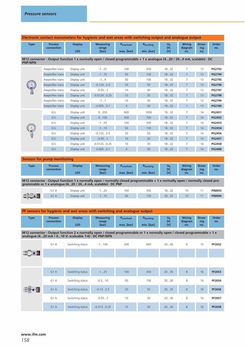
Electronic contact manometers for hygienic and wet areas with switching output and analogue output
Type Processconnection
Display
LED
Measuringrange[bar]
Poverload
max. [bar]
Pbursting
min. [bar]
UbDC[V]
Wiringdiagram
no.
Draw-ingno.
Orderno.
M12 connector · Output function 1 x normally open / closed programmable + 1 x analogue (4...20 / 20...4 mA, scalable) · DCPNP/NPN
Aseptoflex Vario Display unit -1...25 100 350 18...32 7 13 PG2793
Aseptoflex Vario Display unit -1...10 50 150 18...32 7 13 PG2794
Aseptoflex Vario Display unit -1...4 30 100 18...32 7 13 PG2795
Aseptoflex Vario Display unit -0.124...2.5 20 50 18...32 7 13 PG2796
Aseptoflex Vario Display unit -0.05...1 10 30 18...32 7 13 PG2797
Aseptoflex Vario Display unit -0.0124...0.25 10 30 18...32 7 13 PG2798
Aseptoflex Vario Display unit -1...1 10 30 18...32 7 13 PG2799
Aseptoflex Vario Display unit -0.005...0.1 4 30 18...32 7 13 PG2789
G½ Display unit 0...250 600 1000 18...32 7 14 PG2451
G½ Display unit 0...100 300 700 18...32 7 14 PG2452
G½ Display unit -1...25 100 300 18...32 7 14 PG2453
G½ Display unit -1...10 50 150 18...32 7 14 PG2454
G½ Display unit -0.125...2.5 20 50 18...32 7 14 PG2456
G½ Display unit -0.05...1 10 30 18...32 7 14 PG2457
G½ Display unit -0.0125...0.25 10 30 18...32 7 14 PG2458
G½ Display unit -0.005...0.1 4 30 18...32 7 14 PG2489
Sensors for pump monitoring
Type Processconnection
Display
LED
Measuringrange[bar]
Poverload
max. [bar]
Pbursting
min. [bar]
UbDC[V]
Wiringdiagram
no.
Draw-ingno.
Orderno.
M12 connector · Output function 1 x normally open / normally closed programmable + 1 x normally open / normally closed pro-grammable or 1 x analogue (4...20 / 20...4 mA, scalable) · DC PNP
G1 A Display unit -1...25 100 350 18...32 10 11 PIM693
G1 A Display unit -1...10 50 150 18...32 10 11 PIM694
PF sensors for hygienic and wet areas with switching and analogue output
Type Processconnection
Display
LED
Measuringrange[bar]
Poverload
max. [bar]
Pbursting
min. [bar]
UbDC[V]
Wiringdiagram
no.
Draw-ingno.
Orderno.
M12 connector · Output function 2 x normally open / closed programmable or 1 x normally open / closed programmable + 1 xanalogue (4...20 mA / 0...10 V; scaleable 1:4) · DC PNP/NPN
G1 A Switching status -1...100 200 650 20...30 8 15 PF2652
G1 A Switching status -1...25 100 350 20...30 8 16 PF2653
G1 A Switching status -0.5...10 50 150 20...30 8 16 PF2654
G1 A Switching status -0.13...2.5 20 50 20...30 8 16 PF2656
G1 A Switching status -0.05...1 10 30 20...30 8 16 PF2657
G1 A Switching status -0.013...0.25 10 30 20...30 8 16 PF2658
Pressure sensors
158www.ifm.com
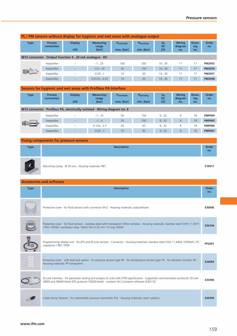
PL / PM sensors without display for hygienic and wet areas with analogue output
Type Processconnection
Display
LED
Measuringrange[bar]
Poverload
max. [bar]
Pbursting
min. [bar]
UbDC[V]
Wiringdiagram
no.
Draw-ingno.
Orderno.
M12 connector · Output function 4...20 mA analogue · DC
Aseptoflex – -1...25 100 350 14...30 11 17 PM2053
Aseptoflex – -0.5...10 50 150 14...30 11 17 PM2054
Aseptoflex – -0.05...1 10 30 14...30 11 17 PM2057
Aseptoflex – -0.0125...0.25 10 30 14...30 11 17 PM2058
Sensors for hygienic and wet areas with Profibus PA Interface
Type Processconnection
Display
LED
Measuringrange[bar]
Poverload
max. [bar]
Pbursting
min. [bar]
UbDC[V]
Wiringdiagram
no.
Draw-ingno.
Orderno.
M12 connector · Profibus PA, electrically isolated · Wiring diagram no. 6
Aseptoflex – -1...10 50 150 9...32 6 18 PMP094
Aseptoflex – -1...4 30 100 9...32 6 18 PMP095
Aseptoflex – -0.124...2.5 20 50 9...32 6 18 PMP096
Aseptoflex – -0.05...1 10 30 9...32 6 18 PMP097
Fixing components for pressure sensors
Type Description Orderno.
Mounting clamp · Ø 34 mm · Housing materials: PBT E10017
Accessories and software
Type Description Orderno.
Protective cover · for fluid sensors with connector M12 · Housing materials: polyurethane E30006
Protective cover · for fluid sensors · stainless steel with transparent Teflon window · Housing materials: stainless steel 316Ti / 1.4571/ PFA / EPDM / ventilation strip: Teflon film 0.32 mm / O-ring: EPDM
E30104
Programming/ display unit · for EPS and IO-Link sensors · Connector · Housing materials: stainless steel 316L / 1.4404 / EPDM/X / PCcopolymer / PBT / FPM
PP2001
Protective cover · with lead seal option · for pressure sensors type PK · for temperature sensors type TK · for vibration monitor VK ·Housing materials: PP transparent
E30094
IO-Link interface · for parameter setting and analysis of units with DTM specification · Supported communication protocols: IO-Link(4800 and 38400 bits/s) EPS protocol (19200 bits/s) · contains ifm Container software (E30110)
E30396
Cable clamp fastener · for submersible pressure transmitter PS3 · Housing materials: steel / plastics E30399
Pressure sensors
159www.ifm.com

Type Description Orderno.
Filter element · for submersible pressure transmitter PS3 · for fixing on the capillary tube E30400
Splitter box · with ventilation and terminal block · for submersible pressure transmitter PS3 · Housing materials: plastics E30401
Additional weight · for submersible pressure transmitter PS3 · Housing materials: stainless steel 316Ti / 1.4571 E30402
Adapters and accessories for adapters
Type Description Orderno.
Adapter · G ¼ - G ¼ · Housing materials: stainless steel / FPM E30007
Adapter · G 1 - G ½ · Housing materials: stainless steel 316L / 1.4404 / sealing: FPM E30116
Flange adapters
Type Description Orderno.
Aseptoflex Vario adapter · Clamp · 1-1.5“ · ISO 2852 · for units with Aseptoflex Vario adapter · Sealing by sealing ring · Housingmaterials: stainless steel 316L / 1.4435
E33201
Aseptoflex Vario adapter · Clamp · 2“ · ISO 2852 · for units with Aseptoflex Vario adapter · Sealing by sealing ring · Housingmaterials: stainless steel 316L / 1.4435
E33202
Aseptoflex Vario adapter · Clamp · 1-1.5“ · ISO 2852 · for units with Aseptoflex Vario adapter · Metal to metal seal · Housingmaterials: stainless steel 316L / 1.4435
E33701
Aseptoflex Vario adapter · Clamp · 2“ · ISO 2852 · for units with Aseptoflex Vario adapter · Metal to metal seal · Housing materials:stainless steel 316L / 1.4435
E33702
Aseptoflex Vario adapter · Varivent type N · DN40 (1.5“), D = 68 · for units with Aseptoflex Vario adapter · Sealing by sealing ring ·Housing materials: stainless steel 316L / 1.4435
E33222
Aseptoflex Vario adapter · Varivent type F · DN25 (1“), D = 50 · for units with Aseptoflex Vario adapter · Metal to metal seal ·Housing materials: stainless steel 316L / 1.4435
E33721
Aseptoflex Vario adapter · Varivent type N · DN40 (1.5“), D = 68 · for units with Aseptoflex Vario adapter · Metal to metal seal ·Housing materials: stainless steel 316L / 1.4435
E33722
Pressure sensors
160www.ifm.com
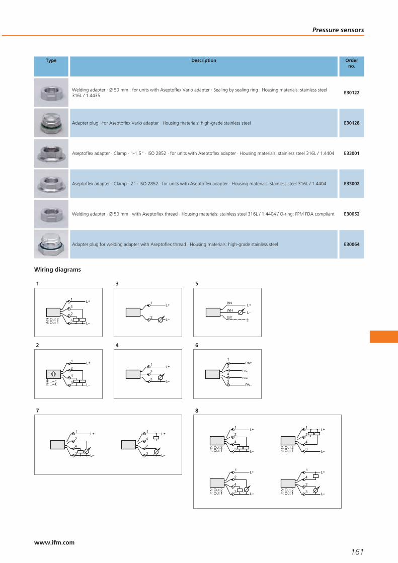
Type Description Orderno.
Welding adapter · Ø 50 mm · for units with Aseptoflex Vario adapter · Sealing by sealing ring · Housing materials: stainless steel316L / 1.4435
E30122
Adapter plug · for Aseptoflex Vario adapter · Housing materials: high-grade stainless steel E30128
Aseptoflex adapter · Clamp · 1-1.5“ · ISO 2852 · for units with Aseptoflex adapter · Housing materials: stainless steel 316L / 1.4404 E33001
Aseptoflex adapter · Clamp · 2“ · ISO 2852 · for units with Aseptoflex adapter · Housing materials: stainless steel 316L / 1.4404 E33002
Welding adapter · Ø 50 mm · with Aseptoflex thread · Housing materials: stainless steel 316L / 1.4404 / O-ring: FPM FDA compliant E30052
Adapter plug for welding adapter with Aseptoflex thread · Housing materials: high-grade stainless steel E30064
Wiring diagrams
1
2
L
L+4
1
3Out 1Out 2
4:2:
2
4
L
L+1
2
32:4:
3
L+
L
1
2
4
L+
L
1
3
2
5
BN
GY
WHL+
L
6
PA
PA+2
4
1
3n.c.
n.c.
7
4
1
3
2L+
L
2
1
3
4L+
L
8
4
L
L+2
1
3Out 1Out 2
4:2:
4
L
L+2
1
3Out 1Out 2
4:2:
4
1
3
2L+
LOut 1Out 2
4:2:
2
1
3
4L+
LOut 1Out 2
4:2:
Pressure sensors
161www.ifm.com

Wiring diagrams
9
4
1
3
2L+
L
L
P
2
L+
L
1
2
1
1: Normal operation, 2: Programming operation (P = communi-cation via EPS / FDT interface)
10
L+
LOut 2Out 1
2:4: 3
4
2
1
L
L+
Out 2Out 1
2:4: 3
4
2
1
11
L+
L
1
2
L+
L
1
3
2
Scale drawings - CAD download: www.ifm.com
1
91,5
34
27
1,3
21,5
2 3
1
30
48
57,3
G
M12
x1
14
1 4/
1: 4-digit alphanumeric display, 2: LEDs (display unit / switching sta-tus), 3: Programming button
2
30
47,8
59,6
G
M12
x1
16,5
1 4/
94,1
34
27
1,3
21,5
2 3
1
1: 4-digit alphanumeric display, 2: LEDs (display unit / switching sta-tus), 3: Programming button
3
91,5
34
27
1,3
21,5
2 3
1
30
47
57,3
G
M12
x1
14
1 4/
1: 4-digit alphanumeric display, 2: LEDs (display unit / switching sta-tus), 3: Programming button
4
4,2
354,75
3220
4232
30
20,7
11,3
1: main pressure connection G 1/8; tightening torque max. 8 Nm,thread length max: 7.5 mm, 2: for mounting screw M4; max. tighte-ning torque 2.5 Nm, 3: LEDs (display unit / switching status), 4: 4-digit alphanumeric display, 5: Programming button
Pressure sensors
162www.ifm.com

Scale drawings - CAD download: www.ifm.com
5
61,6
12
M12 x127
2771
,6
G1 4/M5
7,5
21
1: tightening torque 25 Nm, 2: sealing FPM / DIN 3869-14
6
221
51,2
12
G1 4/
65,1
M12 x122
1: sealing FPM / DIN 3869-14, tightening torque 25 Nm
7
77,5
M12 x130
30
27
1,3
21,5
16,5
G 41
8
75
M12 x130
30
27
1,3
21,5
14
G 41
9
100
27
10
119
34
14,5
2 3
36
1
48
36
47
85M
12x1
4 5
1: 4-digit alphanumeric display, 2: LEDs, 3: Programming button, 4:Aseptoflex sealing edge, 5: Aseptoflex thread
11
G125,4
119
41
34
2 348
27
1
47
85M
12x1
20°
1: 4-digit alphanumeric display, 2: LEDs, 3: Programming button
12
16,8
G1
64
M12
x1
105,
852
,8
50
34
1
2 3
1: 4-digit alphanumeric display, 2: LEDs, 3: Programming button
Pressure sensors
163www.ifm.com
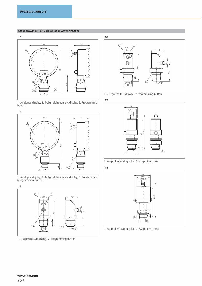
Scale drawings - CAD download: www.ifm.com
13
24
3
153
16,8
100
2
1
57
60,5
M12
x1
G1
1: Analogue display, 2: 4-digit alphanumeric display, 3: Programmingbutton
14
3
169
22
100
2
1
24
75,5
57
M12
x1
G 21
1: Analogue display, 2: 4-digit alphanumeric display, 3: Touch button(programming button)
15
46,5
58M
12x1
41 20°
92
34
M12 x1
27,5
G125,4
1 2
1: 7-segment LED display, 2: Programming button
16
97,4
34
27,5
G125,4
48,51 2
46,5
63,1
M12
x1
41 20°
1: 7-segment LED display, 2: Programming button
17
36
107
34
15
M12 x1
121,
5
48
1 2
1: Aseptoflex sealing edge, 2: Aseptoflex thread
18
14,5
36
58
M12 x150
108 12
2,8
1 2
1: Aseptoflex sealing edge, 2: Aseptoflex thread
Pressure sensors
164www.ifm.com

Pressure sensors
165

166

Temperature sensors
Selection chart Page
Compact temperature sensors 169
Compact temperature sensors with display 169
Control monitors for temperature sensors 169 - 170
Control monitors for temperature sensors 170
Pt1000 probe sensors for standard applications 170
Pt100 probe sensors for standard applications 171
Cable sensors for standard applications 171
Cable sensors with bolt-on sensor for standard applications 171
Temperature transmitters for standard applications 171
AS-i temperature transmitters for standard applications 172
Probe sensors for hygienic and wet areas 172
Cable sensors for hygienic and wet areas 172
Temperature transmitters for hygienic and wet areas 172
AS-i temperature transmitters for hygienic and wet areas 173
Self-monitoring temperature transmitters for hygienic and wet areas 173
Profibus-Temperaturtransmitter mit ATEX-Zulassung 1G, 1/2GD, 2GD 173
Accessories for temperature sensors TN / TR 173
Accessories and software 173
Adapters 174 - 175
Thermowells for temperature sensors 175
Flange adapters 175 - 176
Wiring diagrams 176 - 177
Scale drawings - CAD download: www.ifm.com 177 - 180
167www.ifm.comwww.ifm.com
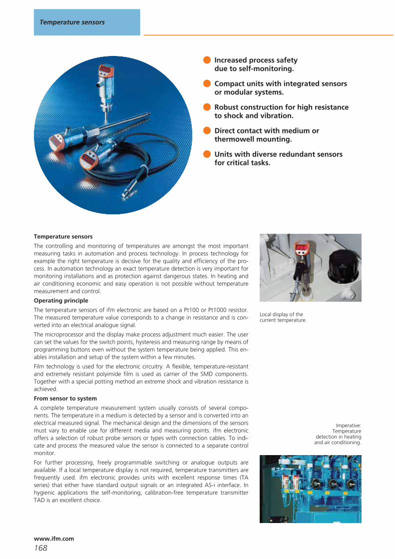
Increased process safety due to self-monitoring.
Compact units with integrated sensorsor modular systems.
Robust construction for high resistanceto shock and vibration.
Direct contact with medium orthermowell mounting.
Units with diverse redundant sensorsfor critical tasks.
Temperature sensors
The controlling and monitoring of temperatures are amongst the most importantmeasuring tasks in automation and process technology. In process technology forexample the right temperature is decisive for the quality and efficiency of the pro-cess. In automation technology an exact temperature detection is very important formonitoring installations and as protection against dangerous states. In heating andair conditioning economic and easy operation is not possible without temperaturemeasurement and control.
Operating principle
The temperature sensors of ifm electronic are based on a Pt100 or Pt1000 resistor.The measured temperature value corresponds to a change in resistance and is con-verted into an electrical analogue signal.
The microprocessor and the display make process adjustment much easier. The usercan set the values for the switch points, hysteresis and measuring range by means ofprogramming buttons even without the system temperature being applied. This en-ables installation and setup of the system within a few minutes.
Film technology is used for the electronic circuitry. A flexible, temperature-resistantand extremely resistant polyimide film is used as carrier of the SMD components.Together with a special potting method an extreme shock and vibration resistance isachieved.
From sensor to system
A complete temperature measurement system usually consists of several compo-nents. The temperature in a medium is detected by a sensor and is converted into anelectrical measured signal. The mechanical design and the dimensions of the sensorsmust vary to enable use for different media and measuring points. ifm electronicoffers a selection of robust probe sensors or types with connection cables. To indi-cate and process the measured value the sensor is connected to a separate controlmonitor.
For further processing, freely programmable switching or analogue outputs areavailable. If a local temperature display is not required, temperature transmitters arefrequently used. ifm electronic provides units with excellent response times (TAseries) that either have standard output signals or an integrated AS-i interface. Inhygienic applications the self-monitoring, calibration-free temperature transmitterTAD is an excellent choice.
Local display of thecurrent temperature.
Imperative:Temperature
detection in heatingand air conditioning.
Temperature sensors
168www.ifm.com
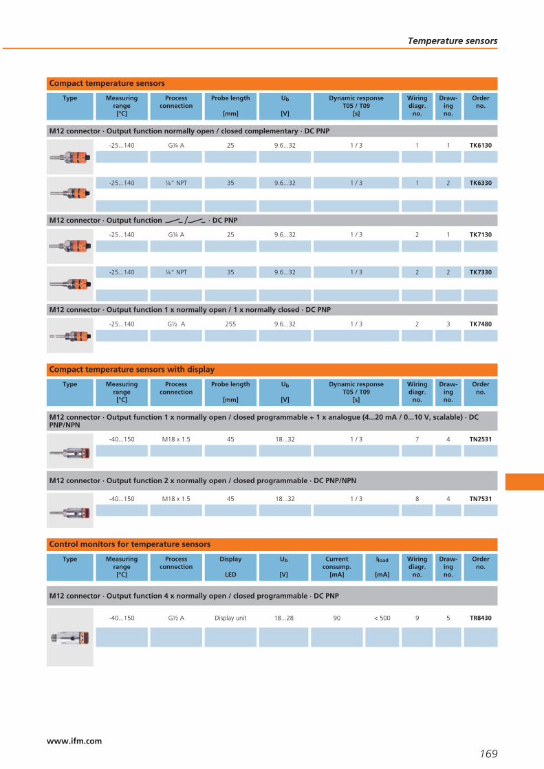
Compact temperature sensors
Type Measuringrange[°C]
Processconnection
Probe length
[mm]
Ub
[V]
Dynamic responseT05 / T09
[s]
Wiringdiagr.
no.
Draw-ingno.
Orderno.
M12 connector · Output function normally open / closed complementary · DC PNP
-25...140 G¼ A 25 9.6...32 1 / 3 1 1 TK6130
-25...140 ¼“ NPT 35 9.6...32 1 / 3 1 2 TK6330
M12 connector · Output function · DC PNP
-25...140 G¼ A 25 9.6...32 1 / 3 2 1 TK7130
-25...140 ¼“ NPT 35 9.6...32 1 / 3 2 2 TK7330
M12 connector · Output function 1 x normally open / 1 x normally closed · DC PNP
-25...140 G½ A 255 9.6...32 1 / 3 2 3 TK7480
Compact temperature sensors with display
Type Measuringrange[°C]
Processconnection
Probe length
[mm]
Ub
[V]
Dynamic responseT05 / T09
[s]
Wiringdiagr.
no.
Draw-ingno.
Orderno.
M12 connector · Output function 1 x normally open / closed programmable + 1 x analogue (4...20 mA / 0...10 V, scalable) · DCPNP/NPN
-40...150 M18 x 1.5 45 18...32 1 / 3 7 4 TN2531
M12 connector · Output function 2 x normally open / closed programmable · DC PNP/NPN
-40...150 M18 x 1.5 45 18...32 1 / 3 8 4 TN7531
Control monitors for temperature sensors
Type Measuringrange[°C]
Processconnection
Display
LED
Ub
[V]
Currentconsump.
[mA]
Iload
[mA]
Wiringdiagr.
no.
Draw-ingno.
Orderno.
M12 connector · Output function 4 x normally open / closed programmable · DC PNP
-40...150 G½ A Display unit 18...28 90 < 500 9 5 TR8430
Temperature sensors
169www.ifm.com

Type Measuringrange[°C]
Processconnection
Display
LED
Ub
[V]
Currentconsump.
[mA]
Iload
[mA]
Wiringdiagr.
no.
Draw-ingno.
Orderno.
M12 connector · Output function 1 x normally open / closed programmable + 1 x analogue (4...20 mA / 0...10 V, scalable) · DCPNP/NPN
-40...300 G½ A Display unit 20...30 55 250 10 5 TR2432
M12 connector · Output function 2 x normally open / closed programmable · DC PNP/NPN
-40...300 G½ A Display unit 18...32 50 250 11 6 TR7432
Control monitors for temperature sensors
Type Measuringrange[°C]
Processconnection
Display
LED
Ub
[V]
Currentconsump.
[mA]
Iload
[mA]
Wiringdiagr.
no.
Draw-ingno.
Orderno.
M12 connector · Output function 4...20 mA analogue · DC
0...100 – – 20...32 – – 12 7 TP3237
Pt1000 probe sensors for standard applications
Type Measuringrange[°C]
Diameter
[mm]
Probe length
[mm]
Sensorelement
Dynamic responseT05 / T09
[s]
Wiringdiagr.
no.
Draw-ingno.
Orderno.
M12 connector · high-grade stainless steel
-40...150 6 160 1 x Pt 1000 1 / 3 3 8 TT1250
-40...150 6 360 1 x Pt 1000 1 / 3 3 8 TT3250
-40...150 10 160 1 x Pt 1000 1 / 3 3 9 TT1050
-40...150 10 260 1 x Pt 1000 1 / 3 3 9 TT2050
-40...150 10 560 1 x Pt 1000 1 / 3 3 9 TT5050
-40...125 8.2 44 1 x Pt 1000 1 / 3 3 10 TM9550
-40...150 10 50 1 x Pt 1000 5 / 14 3 11 TM0061
Temperature sensors
170www.ifm.com
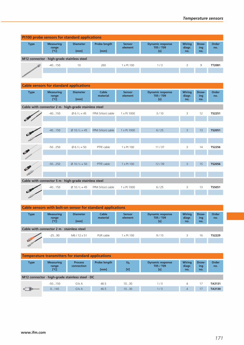
Pt100 probe sensors for standard applications
Type Measuringrange[°C]
Diameter
[mm]
Probe length
[mm]
Sensorelement
Dynamic responseT05 / T09
[s]
Wiringdiagr.
no.
Draw-ingno.
Orderno.
M12 connector · high-grade stainless steel
-40...150 10 260 1 x Pt 100 1 / 3 3 9 TT2081
Cable sensors for standard applications
Type Measuringrange[°C]
Diameter
[mm]
Cablematerial
Sensorelement
Dynamic responseT05 / T09
[s]
Wiringdiagr.
no.
Draw-ingno.
Orderno.
Cable with connector 2 m · high-grade stainless steel
-40...150 Ø 6 / L = 45 FPM (Viton) cable 1 x Pt 1000 3 / 10 3 12 TS2251
-40...150 Ø 10 / L = 45 FPM (Viton) cable 1 x Pt 1000 6 / 25 3 13 TS2051
-50...250 Ø 6 / L = 50 PTFE cable 1 x Pt 100 11 / 37 3 14 TS2256
-50...250 Ø 10 / L = 50 PTFE cable 1 x Pt 100 12 / 39 3 15 TS2056
Cable with connector 5 m · high-grade stainless steel
-40...150 Ø 10 / L = 45 FPM (Viton) cable 1 x Pt 1000 6 / 25 3 13 TS5051
Cable sensors with bolt-on sensor for standard applications
Type Measuringrange[°C]
Diameter
[mm]
Cablematerial
Sensorelement
Dynamic responseT05 / T09
[s]
Wiringdiagr.
no.
Draw-ingno.
Orderno.
Cable with connector 2 m · stainless steel
-25...90 M6 / 12 x 51 PUR cable 1 x Pt 100 9 / 15 3 16 TS2229
Temperature transmitters for standard applications
Type Measuringrange[°C]
Processconnection
Probe length
[mm]
Ub
[V]
Dynamic responseT05 / T09
[s]
Wiringdiagr.
no.
Draw-ingno.
Orderno.
M12 connector · high-grade stainless steel · DC
-50...150 G¼ A 46.5 10...30 1 / 3 4 17 TA3131
0...140 G¼ A 46.5 10...30 1 / 3 4 17 TA3130
Temperature sensors
171www.ifm.com

AS-i temperature transmitters for standard applications
Type Measuringrange[°C]
Processconnection
Probe length
[mm]
Ub
[V]
Dynamic responseT05 / T09
[s]
Wiringdiagr.
no.
Draw-ingno.
Orderno.
M12 connector · high-grade stainless steel · DC
-10...150 G¼ A 46.5 18...31.6 1 / 3 5 18 TAA131
Probe sensors for hygienic and wet areas
Type Measuringrange[°C]
Diameter
[mm]
Probe length
[mm]
Sensorelement
Dynamic responseT05 / T09
[s]
Wiringdiagr.
no.
Draw-ingno.
Orderno.
M12 connector · high-grade stainless steel
-40...150 10 110 1 x Pt 1000 1 / 3 3 9 TT0061
-40...150 10 160 1 x Pt 1000 1 / 3 3 9 TT1061
Cable sensors for hygienic and wet areas
Type Measuringrange[°C]
Diameter
[mm]
Cablematerial
Sensorelement
Dynamic responseT05 / T09
[s]
Wiringdiagr.
no.
Draw-ingno.
Orderno.
Cable with connector 2 m · high-grade stainless steel
-40...150 Ø 10 / L = 45 FPM (Viton) cable 1 x Pt 1000 6 / 25 3 13 TS2051
Cable with connector 5 m · high-grade stainless steel
-40...150 Ø 10 / L = 45 FPM (Viton) cable 1 x Pt 1000 6 / 25 3 13 TS5051
Cable with connector 2 m · high-grade stainless steel
-50...250 Ø 10 / L = 50 PTFE cable 1 x Pt 100 12 / 39 3 15 TS2056
Temperature transmitters for hygienic and wet areas
Type Measuringrange[°C]
Processconnection
Probe length
[mm]
Ub
[V]
Dynamic responseT05 / T09
[s]
Wiringdiagr.
no.
Draw-ingno.
Orderno.
M12 connector · high-grade stainless steel · DC
0...100 G½ A 87.5 10...30 1 / 3 4 19 TA3437
0...140 G½ A 87.5 10...30 1 / 3 4 19 TA3430
-10...150 G½ A 87.5 10...30 1 / 3 4 19 TA3431
-10...150 Ø 6 mm 123 10...30 1.2 / 3.5 4 20 TA3231
Temperature sensors
172www.ifm.com

AS-i temperature transmitters for hygienic and wet areas
Type Measuringrange[°C]
Processconnection
Probe length
[mm]
Ub
[V]
Dynamic responseT05 / T09
[s]
Wiringdiagr.
no.
Draw-ingno.
Orderno.
M12 connector · high-grade stainless steel · DC
-10...150 G½ A 87.5 18...31.6 1 / 3 5 21 TAA431
Self-monitoring temperature transmitters for hygienic and wet areas
Type Measuringrange[°C]
Processconnection
Probe length
[mm]
Ub
[V]
Dynamic responseT05 / T09
[s]
Wiringdiagr.
no.
Draw-ingno.
Orderno.
M12 connector · Output function normally open / normally closed / heartbeat programmable, 4...20 mA analogue · DC PNP/NPN
-25...150 Aseptoflex Vario 87.5 15...32 3 / 6 13 22 TAD181
-25...150 Aseptoflex Vario 33 15...32 3 / 6 13 23 TAD981
Profibus-Temperaturtransmitter mit ATEX-Zulassung 1G, 1/2GD, 2GD
Type Measuringrange[°C]
Processconnection
Probe length
[mm]
Ub
[V]
Dynamic responseT05 / T09
[s]
Wiringdiagr.
no.
Draw-ingno.
Orderno.
M12 connector · Wiring diagram no. 6
-25...150 Aseptoflex Vario 87.5 9...32 3 / 6 6 24 TAP18A
-25...150 Aseptoflex Vario 33 9...32 3 / 6 6 25 TAP98A
Accessories for temperature sensors TN / TR
Type Description Orderno.
Mounting clamp · Ø 34 mm · Housing materials: PBT E10017
Protective cover · for fluid sensors with connector M12 · Housing materials: polyurethane E30006
Accessories and software
Type Description Orderno.
IO-Link interface · for parameter setting and analysis of units with DTM specification · Supported communication protocols: IO-Link(4800 and 38400 bits/s) EPS protocol (19200 bits/s) · contains ifm Container software (E30110)
E30396
Temperature sensors
173www.ifm.com

Adapters
Type Description Orderno.
Thread cover · Ø 26 mm - G ½ · to cover the G½ thread for installation in hygienic areas · for type TA · Housing materials: stainlesssteel 316L / 1.4404
E30090
Mounting set · for direct connection of temperature sensors TT to control monitors TR · Housing materials: stainless steel E30017
Mounting set · G ½ · for direct connection of temperature sensors TM to control monitors TR · Housing materials: stainless steel316L / 1.4404 / stainless steel
E30089
Clamp fitting · Ø 6/8/10 mm - G ½ · for temperature sensors TS / TT · Housing materials: stainless steel / FPM E30018
Clamp adapter · Ø 10 mm - G ½ · no dead space · Housing materials: stainless steel 316L / 1.4404 / FPM E34410
Welding adapter · M18 x 1.5 - Ø 24 mm · Insertion depth of the probe of SID, SFD, TN: · 15 mm · Housing materials: stainless steel316L / 1.4404
E40124
Welding adapter · G ½ - Ø 35 mm · ball · Housing materials: stainless steel 316L / 1.4404 E30055
Welding adapter · G ½ - Ø 45 mm · collar · Housing materials: stainless steel 316L / 1.4404 E30056
Welding adapter · Ø 50 mm · for units with Aseptoflex Vario adapter · Sealing by sealing ring · Housing materials: stainless steel316L / 1.4435
E30122
Progressive ring fitting for temperature sensors · Ø 10 mm - G ½ · Housing materials: stainless steel 316Ti / 1.4571 E30016
Progressive ring fitting for temperature sensors · Ø 6 mm - G ½ · Housing materials: stainless steel 316Ti / 1.4571 E30047
Adapter · M18 x 1.5 - G ½ · Insertion depth of the probe of SID, SFD, TN: · 21 mm · Housing materials: titanium E40114
Adapter · M18 x 1.5 - M12 x 1 · Insertion depth of the probe of SID, SFD, TN: · 13.5 mm · Housing materials: titanium E40128
Adapter · M18 x 1.5 - M12 x 1 · Insertion depth of the probe of SID, SFD, TN: · 13.5 mm · Housing materials: stainless steel 316L /1.4404
E40101
Temperature sensors
174www.ifm.com

Type Description Orderno.
Adapter · M18 x 1.5 - G ¼ · Insertion depth of the probe of SID, SFD, TN: · 13.5 mm · Housing materials: stainless steel 316L /1.4404
E40099
Adapter · M18 x 1.5 - G ½ · Insertion depth of the probe of SID, SFD, TN: · 21 mm · Housing materials: stainless steel 316L / 1.4404 E40096
Adapter · M18 x 1.5 - ½“ NPT · Insertion depth of the probe of SID, SFD, TN: · 23 mm · Housing materials: stainless steel 316L /1.4404
E40107
G ½ adapter · Clamp · 1-1.5“ · DIN 32676 · for units with G ½ adaptation · Housing materials: stainless steel 316L / 1.4404 E33401
G ½ adapter · Clamp · 2“ · DIN 32676 · for units with G ½ adaptation · Housing materials: stainless steel 316L / 1.4404 E33402
Protective cover · with lead seal option · for pressure sensors type PK · for temperature sensors type TK · for vibration monitor VK ·Housing materials: PP transparent
E30094
Thermowells for temperature sensors
Type Description Orderno.
Welding thermowell · Ø 35 mm · Probe length: 126.5 mm · for type TA343x, TAA431, TAD191 · Housing materials: stainless steel316L / 1.4404
E30403
Thermowell for temperature sensors · G ½ · Probe length: 53 mm · for type TA34xx, TAA431, TAD191 · Housing materials: stainlesssteel 316L / 1.4404
E30393
Thermowell for temperature sensors · Ø 10 mm - G ½ · Probe length: 82 mm · Housing materials: stainless steel 316L / 1.4404 E35010
Thermowell for temperature sensors · Ø 6 mm - G ½ · Probe length: 82 mm · Housing materials: stainless steel 316Ti / 1.4571 E37010
Flange adapters
Type Description Orderno.
Aseptoflex Vario adapter · Clamp · 2“ · ISO 2852 · for units with Aseptoflex Vario adapter · Sealing by sealing ring · Housingmaterials: stainless steel 316L / 1.4435
E33202
Aseptoflex Vario adapter · Clamp · 2“ · ISO 2852 · for units with Aseptoflex Vario adapter · Metal to metal seal · Housing materials:stainless steel 316L / 1.4435
E33702
Temperature sensors
175www.ifm.com
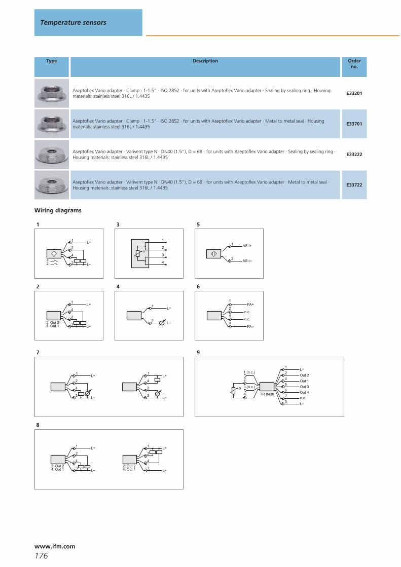
Type Description Orderno.
Aseptoflex Vario adapter · Clamp · 1-1.5“ · ISO 2852 · for units with Aseptoflex Vario adapter · Sealing by sealing ring · Housingmaterials: stainless steel 316L / 1.4435
E33201
Aseptoflex Vario adapter · Clamp · 1-1.5“ · ISO 2852 · for units with Aseptoflex Vario adapter · Metal to metal seal · Housingmaterials: stainless steel 316L / 1.4435
E33701
Aseptoflex Vario adapter · Varivent type N · DN40 (1.5“), D = 68 · for units with Aseptoflex Vario adapter · Sealing by sealing ring ·Housing materials: stainless steel 316L / 1.4435
E33222
Aseptoflex Vario adapter · Varivent type N · DN40 (1.5“), D = 68 · for units with Aseptoflex Vario adapter · Metal to metal seal ·Housing materials: stainless steel 316L / 1.4435
E33722
Wiring diagrams
1
4
L
L+1
2
32:4:
2
2
L
L+4
1
3Out 1Out 2
4:2:
3
1
2
3
4
4
L+
L
1
2
5
AS-i+1
3 AS-i
6
PA
PA+2
4
1
3n.c.
n.c.
7
4
1
3
2L+
L
2
1
3
4L+
L
8
Out 1Out 2
4
L
L+2
1
34:2:
4
L
L+2
1
3Out 1Out 2
4:2:
9
TR 8430
L+
Ln.c.Out 4
Out 1Out 2
124
673
Out 353 (n.c.)
1 (n.c.)
4
2
Temperature sensors
176www.ifm.com

Wiring diagrams
10
L+
L
1 BN
2 WH
4 BK
3 BUTR 2432
1
2
3
4
2
B
1
2
3
4
3
1
1
2
3
4
B
B
1: Two-wire sensor, 2: Three-wire sensor, 3: Four-wire sensor, B:link
11
L+
L
1 BN
2 WH
4 BK
3 BU
1
2
3
4
2
B
1
2
3
4
3
1
1
2
3
4
B
B
TR
1: Two-wire sensor, 2: Three-wire sensor, 3: Four-wire sensor, B:link
12
4
1
3
2L+
L
L
IO-Link1
2
3
4
1
2
3
4
1
2
3
4
B
B
TP
1: Two-wire sensor, 2: Four-wire sensor, 3: Operation as 2-wiretemperature transmitter, 4: Operation as 3-wire unit, IO-Linkcommunication possible, B: link
13
2
L+
L
1
L+
L3 BU
4 BK
2 WH
1 BN
2 WH
1 BN
1: 2-wire operation, 2: 3-wire operation
Scale drawings - CAD download: www.ifm.com
1
39
M12 x127
27
96,5
25
8,2
G 41
87
2
48
M12 x127
27
105,
5
35
8,2
-18 NPT41
96
Temperature sensors
177www.ifm.com

Scale drawings - CAD download: www.ifm.com
3
267
M12 x127
27
327
G 21
8
255
4
4514
128
34
8,2
2 3
1
48
94,5
M12
x1
22 4
1: 4-digit alphanumeric display, 2: LEDs, 3: Programming button, 4:internal thread M18 x 1.5
5
93
34
16,5
G 21
2 3
1
30
48
60M
12x1
4
1: 4-digit alphanumeric display, 2: LEDs, 3: Programming button, 4:connection for temperature sensor
6
93
34
16,5
G 21
2 3
1
30
48
60M
12x1
4
1: 4-digit alphanumeric display, 2: LEDs, 3: Programming button, 4:connection for temperature sensor
7
M12x1 17
M12x1
23,5
LED
20 50
2
1: connection for voltage supply and output signals, 2: connectionfor temperature sensor
8
18,5
L
5,95
M12
x1
21,5
401
6,2 13,8
6
1: plug area
9
8
L
10
M12
x1
21,5
18,5
401
1: plug area
10
90
60
22
14
8,2
44
12
M12x1
19
1
1: internal thread M18 x 1.5
Temperature sensors
178www.ifm.com

Scale drawings - CAD download: www.ifm.com
11
1 2
M12
x136
45
4,5 10
50
30
1: Aseptoflex thread, 2: Aseptoflex sealing edge
12
M12
x1
64572
48
13
46
M12
x1
12
745 10
14
M12
x1
42,5 50 6
15
50
12
10742
M12
x1
42,5
16
M12
x1
49,5
14 35
6,5
51
12
17
8,7
1,8
17
4460
8,2
M12x130
27
13,7
117,
7
13,5
G 41
18
5360
8,2
M12x130
27
14,9
127,
9
13,5
G 41
LED
19
G 21
43,8 123
8,2
10
M12
x130
27
18,3
13,7
47,5
180,5
LED
87,5
20
34 123
6
M12
x130
14171
21
G 21
52,8 123
8,2
10
M12
x130
27
18,3
14,7
47,5
190,5
LED
87,5
Temperature sensors
179www.ifm.com

Scale drawings - CAD download: www.ifm.com
22
34 G1
8 10
50,4
87,5140,5
210,5
M12
x1
195,7
23
34 G1
8 10
50,4
3386
156141,2
M12
x1
24
34 G1
8 10
50,4
87,5140,5
210,5
M12
x1
195,7
1
1: Grounding screw
25
34 G1
8 10
50,4
3386
156141,2
M12
x1
1
1: Grounding screw
Temperature sensors
180www.ifm.com

Temperature sensors
181

182

Diagnostic systems
Selection chart Page
Compact vibration diagnostic units with g-monitor to ISO 10816 type VB/VE 185
Accessories VB / VE 185
Vibration monitors for vibration monitoring of machines and plants to ISO 10816 type VK 185
Accessories VK 186
Diagnostic electronics - control cabinet modules for vibration diagnosis type VSE 186
Accessories VSE 186
Vibration sensors for connection to external diagnostic electronics VSE - type VSA 186 - 187
Accessories VSA 187
Scale drawings - CAD download: www.ifm.com 187 - 188
183www.ifm.comwww.ifm.com

Online vibration diagnosis – optimumprice / performance ratio.
Decentralised monitoring of plant and equipment integrated into the machine.
Compact field units and modular control cabinet units.
Digital and analogue alarm outputs.
Standard data interface (OPC).
Diagnostic systems
efector octavis is a vibration monitor which not only detects vibration data, but alsocarries out signal analysis and machine diagnosis directly on the machine. The ma-chine condition is determined and is forwarded to the PLC or to SCADA software. Itfulfils the main requirements for modern machine monitoring: compatibility, modu-larity and transferable configuration.
Compatible and modular
The compatibility with data structures such as the OPC interface makes it possible tointegrate condition data into a higher-level system. With the requirement for modu-larity the user can define the extent of condition monitoring to be implemented –this means the complete range of diagnosis is possible right from the “first unit”.Transferable configuration is attained with application-related parameter sets. Awizard function in the software guides the user through creating, managing andarchiving the monitoring parameters.
Trend memory
All units of the octavis family type VE / VSE feature an internal trend memory whichensures detailed analysis and optimisation of the application even without externaldata recording. The storage intervals are freely selectable. This means that the sto-rage length of the non volatile ring-memory is adjusted to the requirements.
The suitable system for your application:
Standard vibration characteristic values / permanent machine protection: VSE, VE, VK
Internal trend memory / root cause analysis: VSE, VE
Online diagnosis / early damage detection: VSE (VE partly)
Network capability of the system: VSE (VE partly*)
*Profibus DP gateway
Internal trend memory(type VE / VSE) of allmonitored diagnosisfactors can be evalu-ated via PC software.
Easy vibration moni-toring: type VK
provides a com-bination of switching
output and trans-mitter function in
conjunction with thetried and tested
easy-turn concept.
Diagnostic systems
184www.ifm.com

Compact vibration diagnostic units with g-monitor to ISO 10816 type VB/VE
Type Description Draw-ingno.
Orderno.
Vibration diagnostic unit · Spectral analysis / FFT · Envelope-curve FFT · Peak · V eff RMS · Trend analysis · Connection viaM12 x 1 and M8 x 1 connectors · housing: diecast zinc nickel-plated / keypad: polyester
1 VE1001
Vibration diagnostic unit · Spectral analysis / FFT · Envelope-curve FFT · Peak · V eff RMS · Trend analysis · Connection viaM12 x 1 and M8 x 1 connectors · housing: diecast zinc nickel-plated
2 VE1101
Vibration diagnostic unit · ATEX approval · Group II, category 2D · Group II, category 2G · Spectral analysis / FFT ·Envelope-curve FFT · Trend analysis · Cable · housing: diecast zinc
3 VE113A
Accessories VB / VE
Type Description Orderno.
Parameter setting cable for efector octavis · ifm electronic · straight / straight · 3 m · Housing materials: PUR E11572
USB/RS485 adapter cable · ifm electronic · straight / straight E30098
Y connection cable · ifm electronic · 2 way · Free from halogen · 0.25 m · Housing materials: TPU E11664
Vibration monitors for vibration monitoring of machines and plants to ISO 10816 type VK
Type Description Draw-ingno.
Orderno.
Vibration monitor · Connection via M12 connector · Vibration monitor to DIN ISO 10816 · Measuring range Veff: 0...25mm/s · Switching outputs: normally closed and analogue 4...20 mA · PBT / PC / FPM / stainless steel 316L / 1.4404
4 VKV021
Vibration monitor · Connection via M12 connector · Vibration monitor to DIN ISO 10816 · Measuring range Veff: 0...50mm/s · Switching outputs: normally closed and analogue 4...20 mA · PBT / PC / FPM / stainless steel 316L / 1.4404
4 VKV022
Diagnostic systems
185www.ifm.com

Accessories VK
Type Description Orderno.
Protective cover · with lead seal option · for pressure sensors type PK · for temperature sensors type TK · for vibration monitor VK ·Housing materials: PP transparent
E30094
Diagnostic electronics - control cabinet modules for vibration diagnosis type VSE
Type Description Draw-ingno.
Orderno.
Diagnostic electronics for vibration sensors · Ethernet interface · Switching output, Analogue output · Combiconconnection · PA
5 VSE002
Diagnostic electronics for vibration sensors · 4 sensor inputs 0...10 mA · Ethernet interface · Switching output, Analogueoutput · Combicon connection · PA
6 VSE100
Accessories VSE
Type Description Orderno.
Patch cable · Cross-over patch cable · Cable length 5 m E30112
Vibration sensors for connection to external diagnostic electronics VSE - type VSA
Type Description Draw-ingno.
Orderno.
Vibration sensor · for connection to external diagnostic electronics · Connector · housing: stainless steel 316L / 1.4404 7 VSA001
Vibration sensor · for connection to external diagnostic electronics · Cable with connector · housing: stainless steel 316L /1.4404
8 VSA002
Diagnostic systems
186www.ifm.com
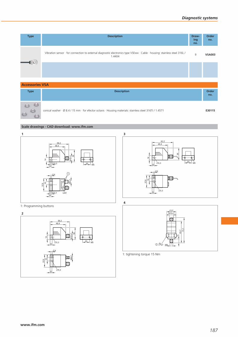
Type Description Draw-ingno.
Orderno.
Vibration sensor · for connection to external diagnostic electronics type VSExxx · Cable · housing: stainless steel 316L /1.4404
9 VSA003
Accessories VSA
Type Description Orderno.
conical washer · Ø 8.4 / 15 mm · for efector octavis · Housing materials: stainless steel 316Ti / 1.4571 E30115
Scale drawings - CAD download: www.ifm.com
1
20 M5
M12
x1
46,458,2
14
65,3
36
37,6
5,35
10
4
M8x
1
LED
1
1: Programming buttons
2
M12
x1
46,458,2
14
65,3
36
20 M5
37,6
5
10
4
5,3
M8x
1
3
20 M5
46,462,2
14
65,3
36
37,6
5
10
4
5,3
4
63,7
11
M12 x127
27
73,1
M81
1: tightening torque 15 Nm
Diagnostic systems
187www.ifm.com
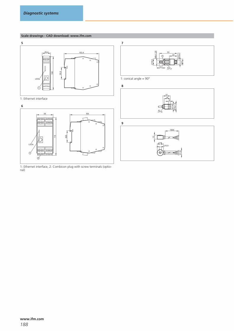
Scale drawings - CAD download: www.ifm.com
5
103,4
35,5
25,410
0
1
LEDs
1: Ethernet interface
6
50
114
LEDs
2
1
105
35,5
1: Ethernet interface, 2: Combicon plug with screw terminals (optio-nal)
7
18,5
M8x
1,25
M12
x117
5324
178
1
1: conical angle = 90°
8
13
M16
x1,5
14
2218
5
9
18
11,5
12
1500
5,5
Diagnostic systems
188www.ifm.com

Diagnostic systems
189

190

Bus system AS-interface
Selection chart Page
Controllers, gateways and software 193
AS-i repeaters 193
AS-i power supplies 194
I/O modules for control cabinets 194 - 195
Field modules IP67 195 - 196
Field modules IP69K and accessories 196
Module lower parts 196 - 197
Pneumatic and actuator solutions 197
Safety at Work 197 - 198
AS-i sensors 198
Combicon connectors 198
Flat cable splitters and accessories 199
Accessories Safety at Work 199
Accessories lower parts and addressing units 199 - 200
Accessories pneumatic components 200
Accessories RFID 200
Scale drawings - CAD download: www.ifm.com 201 - 206
191www.ifm.comwww.ifm.com

Manufacturer-independent standard.
Worldwide acceptance as a wiring system.
Communication from the sensor to the controller.
“Safety at Work” for safety-related applications.
Intelligent system solutions for special tasks.
Bus system AS-interface
AS-interface (AS-i = actuator sensor interface) is a manufacturer-independent stan-dard for the connection of actuators and sensors of the first field level. It is the onlywiring system accepted worldwide. With 15 million slaves installed AS-i has beentried and tested as a low-cost feeder for all common fieldbuses for many years.
The product range includes AS-i components for different areas from packaging andconveying via silo applications, machine tools, robotics and automation to the foodindustry and mobile vehicles.
Safe
The sophisticated AS-i technology and the extended diagnostic possibilities providehigh reliability and machine uptime.
“Safety at Work” is the extension of the AS-interface by safety-related components.Safety components up to the highest control category 4 to EN 954-1, SIL 3 to IEC61508 and EN ISO 13849 - 1 / PL e can be connected to AS-i.
Easy
Due to the standardised system, the low wiring complexity and the quick connectiontechnology, AS-i enables simple “Plug & Play”. The reduction of terminals leads toreduced documentation.
Data and energy are jointly transmitted via a two-wire cable. The reverse polarity pro-tected insulation displacement technology helps avoid errors. The modularity and thetree structure smoothly fit to the way the plant is put together.
Cost-optimised
It’s the end result that matters: wiring complexity, documentation and set-up timesare significantly reduced. The decentralisation of the AS-i participants leads tosmaller and less expensive control cabinets. Simple diagnosis and a clear systemdesign result in high machine uptime and avoid downtimes.
With “Safety atWork” AS-i alsosolves safety-related tasks.
Reduced cost:reduced wiring com-
plexity for fasterinstallation and fewer
error sources.
Bus system AS-interface
192www.ifm.com
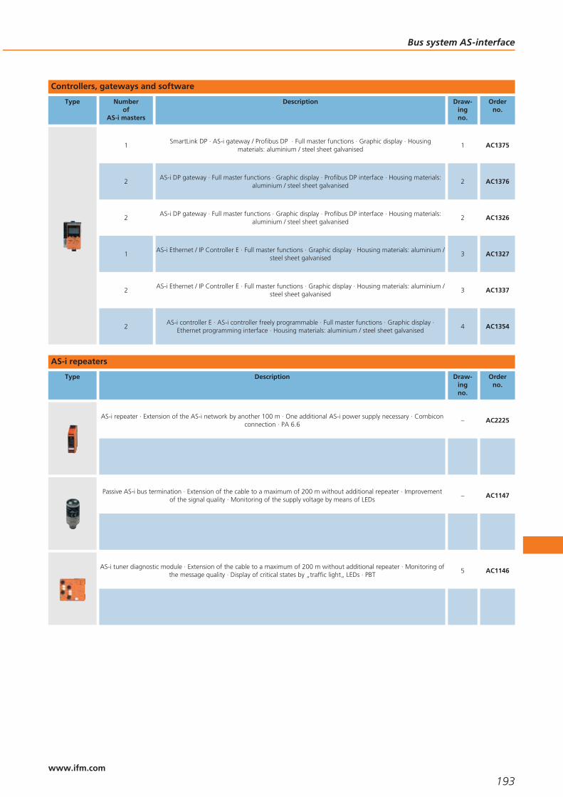
Controllers, gateways and software
Type Numberof
AS-i masters
Description Draw-ingno.
Orderno.
1SmartLink DP · AS-i gateway / Profibus DP · Full master functions · Graphic display · Housing
materials: aluminium / steel sheet galvanised1 AC1375
2AS-i DP gateway · Full master functions · Graphic display · Profibus DP interface · Housing materials:
aluminium / steel sheet galvanised2 AC1376
2AS-i DP gateway · Full master functions · Graphic display · Profibus DP interface · Housing materials:
aluminium / steel sheet galvanised2 AC1326
1AS-i Ethernet / IP Controller E · Full master functions · Graphic display · Housing materials: aluminium /
steel sheet galvanised3 AC1327
2AS-i Ethernet / IP Controller E · Full master functions · Graphic display · Housing materials: aluminium /
steel sheet galvanised3 AC1337
2AS-i controller E · AS-i controller freely programmable · Full master functions · Graphic display ·
Ethernet programming interface · Housing materials: aluminium / steel sheet galvanised4 AC1354
AS-i repeaters
Type Description Draw-ingno.
Orderno.
AS-i repeater · Extension of the AS-i network by another 100 m · One additional AS-i power supply necessary · Combiconconnection · PA 6.6
– AC2225
Passive AS-i bus termination · Extension of the cable to a maximum of 200 m without additional repeater · Improvementof the signal quality · Monitoring of the supply voltage by means of LEDs
– AC1147
AS-i tuner diagnostic module · Extension of the cable to a maximum of 200 m without additional repeater · Monitoring ofthe message quality · Display of critical states by „traffic light„ LEDs · PBT
5 AC1146
Bus system AS-interface
193www.ifm.com
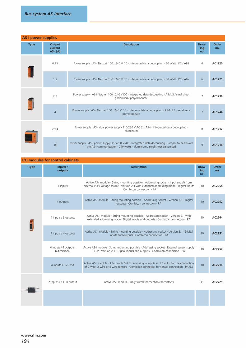
AS-i power supplies
Type OutputcurrentAS-i [A]
Description Draw-ingno.
Orderno.
0.95 Power supply · AS-i Netzteil 100...240 V DC · Integrated data decoupling · 30 Watt · PC / ABS 6 AC1220
1.9 Power supply · AS-i Netzteil 100...240 V DC · Integrated data decoupling · 60 Watt · PC / ABS 6 AC1221
2.8Power supply · AS-i Netzteil 100...240 V DC · Integrated data decoupling · AlMg3 / steel sheet
galvanised / polycarbonate7 AC1236
4Power supply · AS-i Netzteil 100...240 V DC · Integrated data decoupling · AlMg3 / steel sheet /
polycarbonate7 AC1244
2 x 4Power supply · AS-i dual power supply 115/230 V AC 2 x AS-i · Integrated data decoupling ·
aluminium8 AC1212
8Power supply · AS-i power supply 115/230 V AC · Integrated data decoupling · Jumper to deactivate
the AS-i communication · 240 watts · aluminium / steel sheet galvanised9 AC1218
I/O modules for control cabinets
Type Inputs /outputs
Description Draw-ingno.
Orderno.
4 inputsActive AS-i module · String mounting possible · Addressing socket · Input supply from
external PELV voltage source · Version 2.1 with extended addressing mode · Digital inputs· Combicon connection · PA
10 AC2254
4 outputsActive AS-i module · String mounting possible · Addressing socket · Version 2.1 · Digital
outputs · Combicon connection · PA10 AC2252
4 inputs / 3 outputsActive AS-i module · String mounting possible · Addressing socket · Version 2.1 withextended addressing mode · Digital inputs and outputs · Combicon connection · PA
10 AC2264
4 inputs / 4 outputsActive AS-i module · String mounting possible · Addressing socket · Version 2.1 · Digital
inputs and outputs · Combicon connection · PA10 AC2251
4 inputs / 4 outputs;bidirectional
Active AS-i module · String mounting possible · Addressing socket · External sensor supplyPELV · Version 2.1 · Digital inputs and outputs · Combicon connection · PA
10 AC2257
4 inputs 4...20 mAActive AS-i module · AS-i profile S-7.3 · 4 analogue inputs 4...20 mA · For the connectionof 2-wire, 3-wire or 4-wire sensors · Combicon connector for sensor connection · PA 6.6
10 AC2216
2 inputs / 1 LED output Active AS-i module · Only suited for mechanical contacts 11 AC2729
Bus system AS-interface
194www.ifm.com

Type Inputs /outputs
Description Draw-ingno.
Orderno.
4 inputs / 3 outputs Active AS-i module · AS-i version 2.1 with extended addressing mode 12 AC2730
Field modules IP67
Type Inputs /outputs
Description Draw-ingno.
Orderno.
4 inputsActive ClassicLine module · Version 2.11 and 3.0 with extended addressing mode ·Addressing socket · Three orientations of the flat cable are possible · Digital inputs ·
Sockets M12 x 1 · PA13 AC5215
4 outputsActive ClassicLine module · Addressing socket · Three orientations of the flat cable are
possible · Digital outputs · Sockets M12 x 1 · PA13 AC5208
2 outputs / 2 inputsActive ClassicLine module · Version 2.11 and 3.0 with extended addressing mode ·
Addressing socket · Three orientations of the flat cable are possible · Digital outputs andinputs · Sockets M12 x 1 · PA
13 AC5214
4 inputs / 3 outputs;bidirectional
Active ClassicLine module · Addressing socket · Three orientations of the flat cable arepossible · Version 2.11 and 3.0 with extended addressing mode · Digital inputs and
outputs · Sockets M12 x 1 · PA14 AC5204
4 inputs / 4 outputs;bidirectional
Active ClassicLine module · Only for operation with AS-i masters with the profile M4 ·Addressing socket · Three orientations of the flat cable are possible · Version 3.0 with
extended addressing mode · Digital inputs and outputs · Sockets M12 x 1 · PA14 AC5235
2 pushbuttons / 2 LED displaysActive module upper parts AS-i illuminated pushbutton module · Power supply via AS-i
cable · Colour inserts changeable · PBT15 AC2086
2 inputs 4...20 mAActive ClassicLine module · 2 analogue inputs 4...20 mA · For the connection of 2-wire
and 3-wire sensors · Addressing socket · Three orientations of the flat cable are possible ·PA
13 AC5222
4 inputsActive CompactLine module · Version 2.1 with extended addressing mode · IR addressing
possible · Digital inputs · Sockets M12 x 1 · PUR16 AC2457
4 inputsActive CompactLine module · IR addressing possible · high-grade stainless steel · Digital
inputs · Sockets M12 x 1 · PA / stainless steel 316L / 1.440416 AC2451
4 outputsActive CompactLine module · IR addressing possible · Digital outputs · Sockets M12 x 1 ·
PA16 AC2417
2 inputs / 2 outputsActive CompactLine module · IR addressing possible · Digital inputs and outputs · Sockets
M12 x 1 · PA16 AC2411
Bus system AS-interface
195www.ifm.com
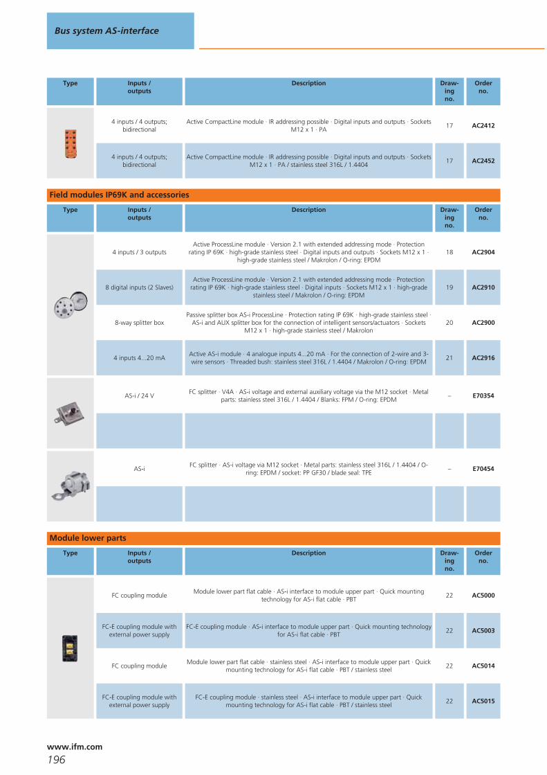
Type Inputs /outputs
Description Draw-ingno.
Orderno.
4 inputs / 4 outputs;bidirectional
Active CompactLine module · IR addressing possible · Digital inputs and outputs · SocketsM12 x 1 · PA
17 AC2412
4 inputs / 4 outputs;bidirectional
Active CompactLine module · IR addressing possible · Digital inputs and outputs · SocketsM12 x 1 · PA / stainless steel 316L / 1.4404
17 AC2452
Field modules IP69K and accessories
Type Inputs /outputs
Description Draw-ingno.
Orderno.
4 inputs / 3 outputsActive ProcessLine module · Version 2.1 with extended addressing mode · Protection
rating IP 69K · high-grade stainless steel · Digital inputs and outputs · Sockets M12 x 1 ·high-grade stainless steel / Makrolon / O-ring: EPDM
18 AC2904
8 digital inputs (2 Slaves)Active ProcessLine module · Version 2.1 with extended addressing mode · Protection
rating IP 69K · high-grade stainless steel · Digital inputs · Sockets M12 x 1 · high-gradestainless steel / Makrolon / O-ring: EPDM
19 AC2910
8-way splitter boxPassive splitter box AS-i ProcessLine · Protection rating IP 69K · high-grade stainless steel ·
AS-i and AUX splitter box for the connection of intelligent sensors/actuators · SocketsM12 x 1 · high-grade stainless steel / Makrolon
20 AC2900
4 inputs 4...20 mAActive AS-i module · 4 analogue inputs 4...20 mA · For the connection of 2-wire and 3-wire sensors · Threaded bush: stainless steel 316L / 1.4404 / Makrolon / O-ring: EPDM
21 AC2916
AS-i / 24 VFC splitter · V4A · AS-i voltage and external auxiliary voltage via the M12 socket · Metal
parts: stainless steel 316L / 1.4404 / Blanks: FPM / O-ring: EPDM– E70354
AS-iFC splitter · AS-i voltage via M12 socket · Metal parts: stainless steel 316L / 1.4404 / O-
ring: EPDM / socket: PP GF30 / blade seal: TPE– E70454
Module lower parts
Type Inputs /outputs
Description Draw-ingno.
Orderno.
FC coupling moduleModule lower part flat cable · AS-i interface to module upper part · Quick mounting
technology for AS-i flat cable · PBT22 AC5000
FC-E coupling module withexternal power supply
FC-E coupling module · AS-i interface to module upper part · Quick mounting technologyfor AS-i flat cable · PBT
22 AC5003
FC coupling moduleModule lower part flat cable · stainless steel · AS-i interface to module upper part · Quick
mounting technology for AS-i flat cable · PBT / stainless steel22 AC5014
FC-E coupling module withexternal power supply
FC-E coupling module · stainless steel · AS-i interface to module upper part · Quickmounting technology for AS-i flat cable · PBT / stainless steel
22 AC5015
Bus system AS-interface
196www.ifm.com
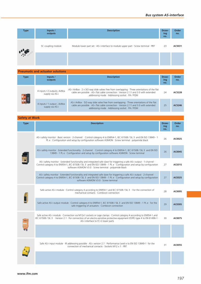
Type Inputs /outputs
Description Draw-ingno.
Orderno.
SC coupling module Module lower part set · AS-i interface to module upper part · Screw terminal · PBT 23 AC5031
Pneumatic and actuator solutions
Type Inputs /outputs
Description Draw-ingno.
Orderno.
4 inputs / 2 outputs; AirBoxsupply via AS-i
AS-i AirBox · 2 x 3/2-way slide valves free from overlapping · Three orientations of the flatcable are possible · AS-i flat cable connection · Version 2.11 and 3.0 with extended
addressing mode · Addressing socket · PA / POM24 AC5228
4 inputs / 1 output ; AirBoxsupply via AS-i
AS-i AirBox · 5/2-way slide valve free from overlapping · Three orientations of the flatcable are possible · AS-i flat cable connection · Version 2.11 and 3.0 with extended
addressing mode · Addressing socket · PA / POM25 AC5246
Safety at Work
Type Description Draw-ingno.
Orderno.
AS-i safety monitor · Basic version · 2-channel · Control category 4 to EN954-1, IEC 61508 / SIL 3 and EN ISO 13849 - 1PL e · Configuration and setup by configuration software ASIMON · Screw terminal · polyamide black
26 AC002S
AS-i safety monitor · Extended functionality · 2-channel · Control category 4 to EN954-1, IEC 61508 / SIL 3 and EN ISO13849 - 1 PL e · Configuration and setup by configuration software ASIMON · Screw terminal
26 AC004S
AS-i safety monitor · Extended functionality and integrated safe slave for triggering a safe AS-i output · 1-channel ·Control category 4 to EN954-1, IEC 61508 / SIL 3 and EN ISO 13849 - 1 PL e · Configuration and setup by configuration
software ASIMON V3.0 · Screw terminal · polyamide black27 AC031S
AS-i safety monitor · Extended functionality and integrated safe slave for triggering a safe AS-i output · 2-channel ·Control category 4 to EN954-1, IEC 61508 / SIL 3 and EN ISO 13849 - 1 PL e · Configuration and setup by configuration
software ASIMON V3.0 · Screw terminal27 AC032S
Safe active AS-i module · Control category 4 according to EN954-1 and IEC 61508 / SIL 3 · For the connection ofmechanical contacts · Combicon connection
28 AC009S
Safe active AS-i output module · Control category 4 to EN954-1, IEC 61508 / SIL 3 and EN ISO 13849 - 1 PL e · for thesafe triggering of actuators · Combicon connection
29 AC030S
Safe active AS-i module · Connection via M12x1 sockets or cage clamps · Control category 4 according to EN954-1 andIEC 61508 / SIL 3 · Version 2.1 · For connection of an electro-sensitive protective equipment (ESPE) type 4 to EN 61496-1 ·
AS-i interface to FC-E lower parts30 AC007S
Safe AS-i input module · IR addressing possible · AS-i version 2.1 · Performance Level e to EN ISO 13849-1 for theconnection of mechanical contacts · Sockets M12 x 1 · PBT
31 AC005S
Bus system AS-interface
197www.ifm.com

Type Description Draw-ingno.
Orderno.
Illuminated E-STOP with integrated AS-i connection · Connector M12 x 1 · AS-i interface via AS-i flat cable IP 67 · fool-proof E-STOP to EN ISO 13850 / EN 418 · Pull to reset
32 AC010S
safe AS-i e-stop operating unit with integrated AS-i connection · AS-i interface via M12 x 1 connector · fool-proof E-STOPto EN ISO 13850 / EN 418 · Pull to reset · interchangeable button inserts
33 AC012S
AS-i safety PCB · Connection of mechanical contact and LED components · Certification according to EN 954-1 / category4 and IEC 61508 / SIL 3
11 AC015S
AS-i sensors
Type Description Draw-ingno.
Orderno.
Read/write head · DTSLF AARWASUS01 · with integrated AS-i slave profile 7.4 · M12 connector · PA 34 DTA100
Read/write head · DTSLF DCRWASUS01 · with integrated AS-i slave profile 7.4 · M12 connector · housing: PPE / Metalparts: diecast zinc / brass nickel-plated
35 DTA300
Combicon connectors
Type Description Orderno.
Combicon connector · with screw terminals 4-pole · Housing materials: current carrying parts: copper alloy tin-plated · Pack quantity:6
E70230
Combicon connector · with screw terminals 4-pole · Housing materials: current carrying parts: copper alloy tin-plated · Pack quantity:100
E70231
Bus system AS-interface
198www.ifm.com

Flat cable splitters and accessories
Type Description Orderno.
FC splitter · AS-i voltage via M12 socket · Housing materials: Metal parts: stainless steel 316L / 1.4404 / O-ring: EPDM / socket: PPGF30 / blade seal: TPE
E70454
FC splitter · V4A · AS-i voltage and external auxiliary voltage via the M12 socket · Housing materials: Metal parts: stainless steel 316L/ 1.4404 / Blanks: FPM / O-ring: EPDM
E70354
FC insulation displacement connector · Socket M12 - AS-i flat cable · Housing materials: PA E70096
Protective cap · M12 · for M12 sockets of ClassicLine modules, CompactLine modules and AirBoxes · Housing materials: PA black E73004
Protective cap · M12 · for M12 socket to cover the unused inputs and outputs on the module; for unused inputs of splitter boxes ·for ProcessLine modules · Housing materials: PVC
E70297
Accessories Safety at Work
Type Description Orderno.
Connection cable PC / AS-i safety monitor · Parameter setting cable PC / AS-i safety monitor · Western connector RJ 45 8 poles / D-Sub socket 9 poles · 2.5 m
E7001S
bridging plug for safety modules · Housing materials: PUR E7005S
Accessories lower parts and addressing units
Type Description Orderno.
AS-i addressing unit · AS-i version 2.1 with extended addressing mode AC1144
Addressing cable · for AS-i slaves · 1.6 m E70213
Programming cable for controller E · Western connector RJ11 6 poles / D-Sub socket 9 poles · 1.55 m E70320
Module lower part set · Screw terminal · Housing materials: PBT AC5031
Bus system AS-interface
199www.ifm.com

Type Description Orderno.
Use of the lower part as branching box · Housing materials: plastics AC3000
AS-i flat cable · reverse polarity protection due to special shape · for use in isolation displacement connector technology for FC lowerparts and compact modules
AC4000
AS-i flat cable · reverse polarity protection due to special shape · for use in isolation displacement connector technology for FC lowerparts and compact modules
AC4002
AS-i flat cable · for the food industry · reverse polarity protection due to special shape · 100 m AC4007
AS-i flat cable · for the food industry · reverse polarity protection due to special shape · 100 m AC4008
JOKARI flat cable stripping tool E70062
Flat cable seal · Housing materials: ULTRAMID / sealing: NBR · Pack quantity: 10 E70413
Accessories pneumatic components
Type Description Orderno.
Silencer · Housing materials: connection piece: PP / filter: PE E75232
Accessories RFID
Type Description Orderno.
ID tag · ID-TAG/TRIANGEL HOUSING/01 · with ID tag E80301 · Housing materials: PBT orange (RAL 2003) / PA black (RAL 9005) E80302
ID tag · ID-TAG/D20x2.15/01 · Ø 20 x 2.15 mm · Housing materials: polycarbonate black E80317
ID tag · ID-TAG/ISO-Card/01 · 54 x 86 x 1 mm · Housing materials: PVC white E80320
Bus system AS-interface
200www.ifm.com

Scale drawings - CAD download: www.ifm.com
1
85
124
138
LED
62
4
6857
2
4
10797
86
124
131
LED
62
LED
3
4
10797
86
124
131
LED
62
LED
4
86
124
131
LED
62
4
10797
5
44
83
90
M12 x1
LED
1 2
1: tune button, 2: mode selector
6
45 100
90
LED
Bus system AS-interface
201www.ifm.com

Scale drawings - CAD download: www.ifm.com
7
136144
136
50
129
LED
8
113118,5
134
120
9
4
10796
91
124
131
Jumper
LED
10
105
35,5
25
114
LEDs
1
1: Addressing socket
11
921 U U UU
44
32
9 10 10
12
88
44
13
14
Bus system AS-interface
202www.ifm.com
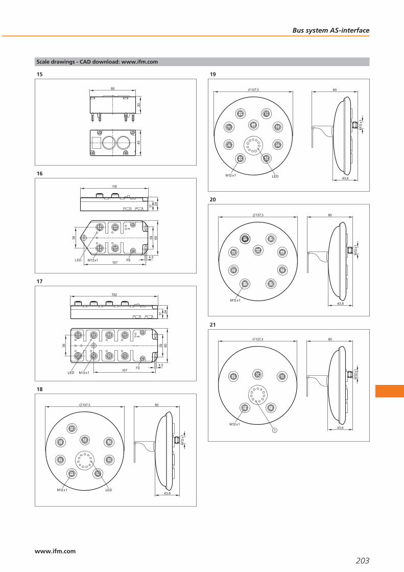
Scale drawings - CAD download: www.ifm.com
15
4530
80
16
17 24
118
FE
60
107
39
4,5
36
LED M12x1
17
60
107
39
4,5
36
M12x1LEDFE
152
17 24
18
M12
x1
43,6
80137,3
M12 x1 LED
19
137,3
M12 x1 LED
M12
x1
43,6
80
20
M12
x1
43,6
80137,3
M12 x1
21
137,3
M12 x1
1
M12
x1
43,6
80
Bus system AS-interface
203www.ifm.com

Scale drawings - CAD download: www.ifm.com
22
80
206
35
66
31
9,65,3
45
7 7
77
23
8082,5
336
35
66
45
9,65,3
31
7 7
77
24
2
4
0
1
0
1
9110
8
85
1 50
40
25
1 50
40
2
4
0
1
9110
8
85
26
120
35,5
45
104
LED
27
45
105,
9
120
35,5
102
82,6
91,2
Bus system AS-interface
204www.ifm.com

Scale drawings - CAD download: www.ifm.com
28
105
35,5
2510
8
LEDs
1
1: Addressing socket
29
2
105
35,5
25
108
1
1: Addressing socket, 2: LED
30
45,5
49,4
8011
1
31
25
80
45
LEDM12x1
32
58,5
66,5
UU
UU
93,5
5610
5
M12
x1
72
80
33
5610
5
207
12072
M12
x1
80
34
5
2
41
4,517
56
17
4,25,5
M12 x1
24
5570
LED
2
1
53,5
1: integrated antenna , 2: tag positioning mark (middle of the anten-na)
Bus system AS-interface
205www.ifm.com

Scale drawings - CAD download: www.ifm.com
35
92
80
40
7,565
65
5,59,3
M12
x1
112
40
LED171
20
1: mounting on DIN rail
Bus system AS-interface
206www.ifm.com

Bus system AS-interface
207

208

Multicode reading systems
Selection chart Page
Multicode reader 211
Accessories 211
Scale drawings - CAD download: www.ifm.com 211
209www.ifm.comwww.ifm.com

Orientation-independent identification of 1D and 2D codes.
Very small housing for flexible use.
Simple, menu-guided parameter setting.
Integrated lighting.
High reading reliability even with soiled / damaged codes.
Multicode reader
The ECC200 Data Matrix code is becoming more and more popular throughoutindustry alongside familiar barcodes. In this code lots of information can be stored ina very small space and read using the compact multicode reader. The industriallycompatible mounting and wiring technology as well as the standardised processinterfaces RS-232, Ethernet TCP/IP and EtherNet/IP enable easy and quick integrationinto the industrial control technology. Applications can be found in many differentindustrial areas: from the product tracking and production control to product identi-fication.
Orientation-independent reading
Independent of the orientation and the number of codes, the high-performancealgorithms automatically decode 1D or 2D codes. The optimisation parameters of thecodes and functions of the multicode reader undergo continuous development andare made available as upgrades.
Code comparison in the sensor
Complex application programming is no longer necessary due to adjustable, selec-tive code identification and comparison in the sensor. This allows a defined numberof characters within a code to be checked and signalled via the switching output ifthey match.
Reliable identification of 1D and 2D codes
In addition to the automatic exposure setting, manual adjustment is also possible. Sooptimum results are achieved even with highly reflective metal surfaces. For evalua-tion of the code quality parameter, ISO / IEC 15415 or 16022 can be used.
The Data Matrix code
The Data Matrix code is a two-dimensional code containing much more informationwith the same structure size than codes such as bar codes or stacked codes. Severalthousand characters can be stored in one code.
An important feature of the Data Matrix code is the high reading reliability. Ifthe code is soiled or damaged, the intelligent system can completely recomposethe information from different segments again. The Data Matrix code can bestructured differently and is variable in shape and size. The size can cover 1 x 1 mmto 100 x 100 mm.
Lose no time: themulticode reader canbe configured in afew minutes and isthen ready for use.Only five guided stepsare necessary for themulticode reader tobe ready for opera-tion. Whether printed
on paper, graved bylaser or dot-peened
on metal: reliable de-tection of the code,independent of thesensor orientation.
Multicode reading systems
210www.ifm.com
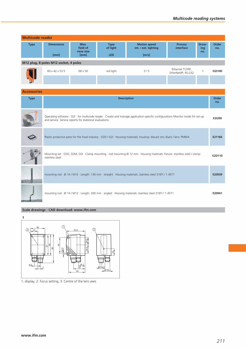
Multicode reader
Type Dimensions
[mm]
Max.field of
view size[mm]
Typeof light
LED
Motion speedint. / ext. lighting
[m/s]
Processinterface
Draw-ingno.
Orderno.
M12 plug, 8 poles M12 socket, 4 poles
60 x 42 x 53.5 68 x 50 red light 3 / 5Ethernet TCP/IP,
EtherNet/IP, RS-2321 O2I100
Accessories
Type Description Orderno.
Operating software · O2I · for multicode reader · Create and manage application-specific configurations Monitor mode for set-upand service Service reports for statistical evaluations
E2I200
Plastic protective pane for the food industry · O2D / O2I · Housing materials: housing: diecast zinc black / lens: PMMA E21166
Mounting set · O2D, O2M, O2I · Clamp mounting · rod mounting Ø 12 mm · Housing materials: fixture: stainless steel / clamp:stainless steel
E2D110
mounting rod · Ø 14 / M12 · Length: 130 mm · straight · Housing materials: stainless steel 316Ti / 1.4571 E20939
mounting rod · Ø 14 / M12 · Length: 200 mm · angled · Housing materials: stainless steel 316Ti / 1.4571 E20941
Scale drawings - CAD download: www.ifm.com
1
M12x1
2
19
M12x1
53,5
4,3
20,5
44
19,733
1
45
24,5
42
57
8060
21
9,57
3
1: display, 2: Focus setting, 3: Centre of the lens axes
Multicode reading systems
211www.ifm.com

212

RF-identification systems
Selection chart Page
RFID systems 215
Accessories 215
Wiring diagrams 215
Scale drawings - CAD download: www.ifm.com 216
213www.ifm.comwww.ifm.com

RFID write and read heads and aselection of tags.
Industrial ident system using the125 kHz range.
Up to 31 compact read / write headsper evaluation module.
Read or write up to 15 bits within20 milliseconds.
Data interface to high end systems;Profibus, DeviceNet, ethernet and others.
RF-identification systems
The constant increase of the degree of automation in modern production plants isincreasingly supported by identification systems. Their tasks include for example thecontrol or release of production steps or the assignment of information about eachproduct.
The RF identification system (Radio Frequency Identification System) from ifm elec-tronic is a compact and easy alternative for applications in which for example opticalidentification is not possible due to the ambient conditions. It is also the first RF iden-tification system for AS-interface worldwide. It allows reading and writing of codecarriers (ID tags), benefiting from the advantages of AS-interface.
It can be integrated into existing AS-I networks without problem and is immediatelyready for operation. For reading, the RF identification system uses the AS-i analogueprotocol 7.4 for data transfer. Special software modules are not required. Up to 31read/write heads can be connected to one AS-i master.
The read/write head stores transmission errors which can be retrieved for a targetedfault analysis. Antenna, electronics and AS-interface are integrated in a compacthousing. The voltage is supplied via the AS-i network via a rotatable M12 connector.No additional operating voltage required.
The ID TAG (transponder) provides flexible mounting options for workpiece carriers,tanks, etc., ...
Operating principle
The RFID system from ifm electronic generates a 125 kHz electromagnetic field forreading and writing of data. The electromagnetic field emitted by the antenna indu-ces voltage in the passive ID tag (transformer principle). This activates the ID tag(transponder) which returns its code. Processing of the code and transmission to theAS-interface are carried out in the read / write head. Advantages: reliable data trans-mission in dynamic reading processes and ID tags for each application.
The read / write headsexchange data withthe passive ID tags ata maximum distanceof 20 mm. The ID tagprovides flexibility fordifferent types ofmounting.
The ID tag is mountedto tanks or workpiece
carriers – in the tagfixture or alternatively
by direct mountingusing an M5 grub
screw.
RF-identification systems
214www.ifm.com

RFID systems
Type Dimensions
[mm]
Travel speedread / write
[m/s]
Processinterface
Wiringdiagram
no.
Draw-ingno.
Orderno.
M12 connector
55 x 24 x 41 read: ≤ 0.5 (distance to the ID tag 15 mm) write: only static AS-i 1 1 DTA100
92 x 80 x 40 read: ≤ 0.5 (distance to the ID tag 40 mm) write: only static AS-i 1 2 DTA300
Accessories
Type Description Orderno.
ID tag · ID-TAG/TRIANGEL HOUSING/01 · with ID tag E80301 · Housing materials: PBT orange (RAL 2003) / PA black (RAL 9005) E80302
ID tag · ID-TAG/D20x2.15/01 · Ø 20 x 2.15 mm · Housing materials: polycarbonate black E80317
ID tag · ID-TAG/ISO-Card/01 · 54 x 86 x 1 mm · Housing materials: PVC white E80320
Dovetail clamp · for type DTS, O4, O5 · Housing materials: AlMgSi0.5 E21088
Wiring diagrams
1
AS-i+1
3 AS-i
RF-identification systems
215www.ifm.com

Scale drawings - CAD download: www.ifm.com
15
2
41
4,517
56
17
4,25,5
M12 x1
24
5570
LED
2
1
53,5
1: integrated antenna , 2: tag positioning mark (middle of the anten-na)
2
92
80
40
7,565
65
5,59,3
M12
x1
112
40
LED171
20
1: mounting on DIN rail
RF-identification systems
216www.ifm.com

RF-identification systems
217

218

Power supplies
Selection chart Page
Switched-mode power supplies 221
Scale drawings - CAD download: www.ifm.com 221 - 222
219www.ifm.comwww.ifm.com
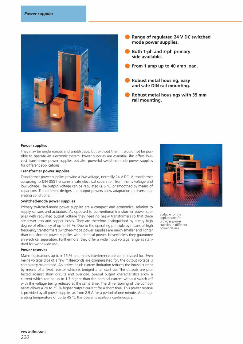
Range of regulated 24 V DC switchedmode power supplies.
Both 1-ph and 3-ph primaryside available.
From 1 amp up to 40 amp load.
Robust metal housing, easy and safe DIN rail mounting.
Robust metal housings with 35 mmrail mounting.
Power supplies
They may be unglamorous and unobtrusive, but without them it would not be pos-sible to operate an electronic system. Power supplies are essential. ifm offers low-cost transformer power supplies but also powerful switched-mode power suppliesfor different applications.
Transformer power supplies
Transformer power supplies provide a low voltage, normally 24 V DC. A transformeraccording to DIN 0551 ensures a safe electrical separation from mains voltage andlow voltage. The output voltage can be regulated (± 5 %) or smoothed by means ofcapacitors. The different designs and output powers allow adaptation to diverse op-erating conditions.
Switched-mode power supplies
Primary switched-mode power supplies are a compact and economical solution tosupply sensors and actuators. As opposed to conventional transformer power sup-plies with regulated output voltage they need no heavy transformers so that thereare fewer iron and copper losses. They are therefore distinguished by a very highdegree of efficiency of up to 92 %. Due to the operating principle by means of highfrequency transformers switched-mode power supplies are much smaller and lighterthan transformer power supplies with identical power. Nevertheless they guaranteean electrical separation. Furthermore, they offer a wide input voltage range as stan-dard for worldwide use.
Power reserves
Mains fluctuations up to ± 15 % and mains interference are compensated for. Evenmains voltage dips of a few milliseconds are compensated for, the output voltage iscompletely maintained. An active inrush current limitation reduces the inrush currentby means of a fixed resistor which is bridged after start up. The outputs are pro-tected against short circuits and overload. Special output characteristics allow acurrent which can be up to 1.7 higher than the nominal current without switch-offwith the voltage being reduced at the same time. The dimensioning of the compo-nents allows a 20 to 25 % higher output current for a short time. This power reserveis provided by all power supplies as from 2.5 A for a period of one minute. At an op-erating temperature of up to 45 °C this power is available continuously.
Suitable for theapplication: ifmprovides powersupplies in differentpower classes.
Power supplies
220www.ifm.com

Switched-mode power supplies
Type Current
[A]
Output voltage
[V]
Nominal voltage
[V]
Efficiencytyp.[%]
Draw-ingno.
Orderno.
10 24...28 DC (±2%) 115 / 230 AC 90 1 DN2013
20 24...28 DC (±2%) 230 AC 91 2 DN2014
5 24...28 DC (±2%) 3 x 400...500 AC 89 3 DN2032
10 24...28 DC (±2%) 3 x 400...500 AC 90 4 DN2033
30 24...28 DC (±2%) 3 x 400...500 AC 93 5 DN2036
40 24...28 DC (±2%) 3 x 400...500 AC 92.5 6 DN2035
1.25 24...28 – 84 7 DN1030
2.5 24...28 – 88 7 DN1031
2.5 24...28 – 87.1 8 DN3011
5 24...28 – 88.9 8 DN3012
Scale drawings - CAD download: www.ifm.com
1
89
4
107
124
120
131
LED
2
124
220
131
LED
227
89
4
107
Power supplies
221www.ifm.com

Scale drawings - CAD download: www.ifm.com
3
124
73
LED
131
4 122
103
4
4
121110
90
124
131
3
2
1
6
5
4
1: LED red, 2: reset push button, 3: jumper „overload performance“,4: jumper „single/parallel operation“, 5: with pot., 6: LED green
5
89
4
107
124
240
131
LED
247
6
89
4
107
124
275
131
282
LED
7
45 100
90
LED
1: with pot.
8
136144
136
50
129
1
LEDs
1: with pot.
Power supplies
222www.ifm.com

Power supplies
223

224

Connection technology
Selection chart Page
Sockets for industrial applications 227
Sockets for industrial applications 227 - 228
Cable plugs for industrial applications 228
Connectors for oils and coolants 229
Connectors for oils and coolants 229
Connectors for electromagnetric fields 229
Connectors for hygienic and wet areas 230 - 231
Connectors for hazardous areas 231
Scale drawings - CAD download: www.ifm.com 231 - 234
225www.ifm.comwww.ifm.com
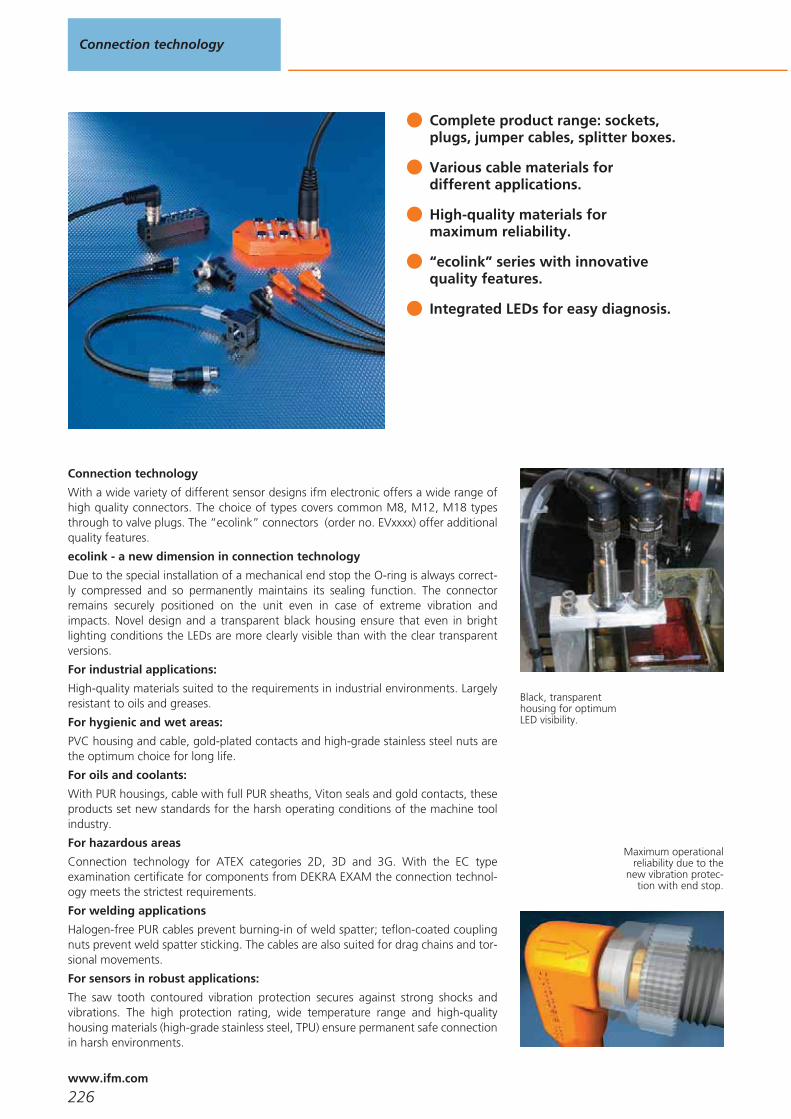
Complete product range: sockets, plugs, jumper cables, splitter boxes.
Various cable materials for different applications.
High-quality materials for maximum reliability.
“ecolink” series with innovative quality features.
Integrated LEDs for easy diagnosis.
Connection technology
With a wide variety of different sensor designs ifm electronic offers a wide range ofhigh quality connectors. The choice of types covers common M8, M12, M18 typesthrough to valve plugs. The “ecolink” connectors (order no. EVxxxx) offer additionalquality features.
ecolink - a new dimension in connection technology
Due to the special installation of a mechanical end stop the O-ring is always correct-ly compressed and so permanently maintains its sealing function. The connectorremains securely positioned on the unit even in case of extreme vibration andimpacts. Novel design and a transparent black housing ensure that even in brightlighting conditions the LEDs are more clearly visible than with the clear transparentversions.
For industrial applications:
High-quality materials suited to the requirements in industrial environments. Largelyresistant to oils and greases.
For hygienic and wet areas:
PVC housing and cable, gold-plated contacts and high-grade stainless steel nuts arethe optimum choice for long life.
For oils and coolants:
With PUR housings, cable with full PUR sheaths, Viton seals and gold contacts, theseproducts set new standards for the harsh operating conditions of the machine toolindustry.
For hazardous areas
Connection technology for ATEX categories 2D, 3D and 3G. With the EC typeexamination certificate for components from DEKRA EXAM the connection technol-ogy meets the strictest requirements.
For welding applications
Halogen-free PUR cables prevent burning-in of weld spatter; teflon-coated couplingnuts prevent weld spatter sticking. The cables are also suited for drag chains and tor-sional movements.
For sensors in robust applications:
The saw tooth contoured vibration protection secures against strong shocks andvibrations. The high protection rating, wide temperature range and high-qualityhousing materials (high-grade stainless steel, TPU) ensure permanent safe connectionin harsh environments.
Black, transparenthousing for optimumLED visibility.
Maximum operationalreliability due to the
new vibration protec-tion with end stop.
Connection technology
226www.ifm.com
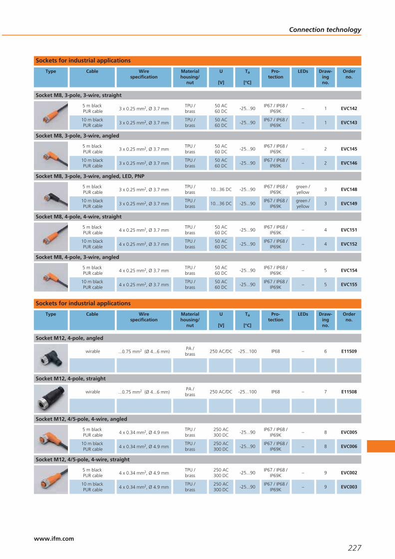
Sockets for industrial applications
Type Cable Wirespecification
Materialhousing/
nut
U
[V]
Ta
[°C]
Pro-tection
LEDs Draw-ingno.
Orderno.
Socket M8, 3-pole, 3-wire, straight
5 m blackPUR cable 3 x 0.25 mm2, Ø 3.7 mm
TPU /brass
50 AC60 DC
-25...90IP67 / IP68 /
IP69K– 1 EVC142
10 m blackPUR cable 3 x 0.25 mm2, Ø 3.7 mm
TPU /brass
50 AC60 DC
-25...90IP67 / IP68 /
IP69K– 1 EVC143
Socket M8, 3-pole, 3-wire, angled
5 m blackPUR cable 3 x 0.25 mm2, Ø 3.7 mm
TPU /brass
50 AC60 DC
-25...90IP67 / IP68 /
IP69K– 2 EVC145
10 m blackPUR cable 3 x 0.25 mm2, Ø 3.7 mm
TPU /brass
50 AC60 DC
-25...90IP67 / IP68 /
IP69K– 2 EVC146
Socket M8, 3-pole, 3-wire, angled, LED, PNP
5 m blackPUR cable 3 x 0.25 mm2, Ø 3.7 mm
TPU /brass
10...36 DC -25...90IP67 / IP68 /
IP69Kgreen /yellow
3 EVC148
10 m blackPUR cable 3 x 0.25 mm2, Ø 3.7 mm
TPU /brass
10...36 DC -25...90IP67 / IP68 /
IP69Kgreen /yellow
3 EVC149
Socket M8, 4-pole, 4-wire, straight
5 m blackPUR cable 4 x 0.25 mm2, Ø 3.7 mm
TPU /brass
50 AC60 DC
-25...90IP67 / IP68 /
IP69K– 4 EVC151
10 m blackPUR cable 4 x 0.25 mm2, Ø 3.7 mm
TPU /brass
50 AC60 DC
-25...90IP67 / IP68 /
IP69K– 4 EVC152
Socket M8, 4-pole, 3-wire, angled
5 m blackPUR cable 4 x 0.25 mm2, Ø 3.7 mm
TPU /brass
50 AC60 DC
-25...90IP67 / IP68 /
IP69K– 5 EVC154
10 m blackPUR cable 4 x 0.25 mm2, Ø 3.7 mm
TPU /brass
50 AC60 DC
-25...90IP67 / IP68 /
IP69K– 5 EVC155
Sockets for industrial applications
Type Cable Wirespecification
Materialhousing/
nut
U
[V]
Ta
[°C]
Pro-tection
LEDs Draw-ingno.
Orderno.
Socket M12, 4-pole, angled
wirable ...0.75 mm2 (Ø 4...6 mm)PA /brass
250 AC/DC -25...100 IP68 – 6 E11509
Socket M12, 4-pole, straight
wirable ...0.75 mm2 (Ø 4...6 mm)PA /brass
250 AC/DC -25...100 IP68 – 7 E11508
Socket M12, 4/5-pole, 4-wire, angled
5 m blackPUR cable 4 x 0.34 mm2, Ø 4.9 mm
TPU /brass
250 AC300 DC
-25...90IP67 / IP68 /
IP69K– 8 EVC005
10 m blackPUR cable 4 x 0.34 mm2, Ø 4.9 mm
TPU /brass
250 AC300 DC
-25...90IP67 / IP68 /
IP69K– 8 EVC006
Socket M12, 4/5-pole, 4-wire, straight
5 m blackPUR cable 4 x 0.34 mm2, Ø 4.9 mm
TPU /brass
250 AC300 DC
-25...90IP67 / IP68 /
IP69K– 9 EVC002
10 m blackPUR cable 4 x 0.34 mm2, Ø 4.9 mm
TPU /brass
250 AC300 DC
-25...90IP67 / IP68 /
IP69K– 9 EVC003
Connection technology
227www.ifm.com

Type Cable Wirespecification
Materialhousing/
nut
U
[V]
Ta
[°C]
Pro-tection
LEDs Draw-ingno.
Orderno.
socket M12, 8-pole, 7-wire + screen
2 m orangePUR cable 7 x 0.25 mm2 + screen
TPU /brass
30 AC36 DC
-25...90 IP67 – 10 E20738
socket M12, 8-pole, 8-wire, for temperature sensors TR 8...
5 m blackPUR cable 8 x 0.25 mm2, Ø 6.2 mm
PUR /brass
30 AC36 DC
-25...80 IP68 – 11 E11232
Socket M16, 14-pole, 12-wire, angled
5 m blackPUR cable
10 x 0.25 mm2 + 2 x0.34 mm2, Ø 7.5 mm
PUR /brass
30 DC -25...90 IP67 – 12 E11697
socket 1/2“, 2-pole + PE, 3-wire
5 m yellowPVC cable 3 x 0.34 mm2, Ø 5.2 mm
TPU /brass
250 AC300 DC
-25...90 IP67 – 13 E10200
5 m yellowPVC cable
3 x AWG22, Ø 5.2 mmTPU /brass
250 AC300 DC
-25...90 IP67 – 14 E10191
socket 1/2“, 5-pole, 4-wire
5 m blackPUR cable 4 x 0.34 mm2, Ø 4.7 mm
TPU /brass
300 AC -25...90 IP67 – 15 E11248
10 m blackPUR cable 4 x 0.34 mm2, Ø 4.7 mm
TPU /brass
300 AC -25...90 IP67 – 15 E11249
Cable plugs for industrial applications
Type Cable Wirespecification
Materialhousing/
nut
U
[V]
Ta
[°C]
Pro-tection
LEDs Draw-ingno.
Orderno.
Plug M12, 4-pole, angled
wirable ...0.75 mm2 (Ø 4...6 mm)PA /brass
250 AC/DC -25...100 IP68 – 16 E11505
Plug M12, 4-pole, straight
wirable ...0.75 mm2 (Ø 4...6 mm)PA /brass
250 AC/DC -25...100 IP68 – 17 E11504
Plug M12, 5-pole, 5-wire, straight
2 m blackPUR cable 5 x 0.34 mm2, Ø 4.9 mm
TPU /brass
30 AC36 DC
-25...90IP67 / IP68 /
IP69K– 18 EVC094
Connection technology
228www.ifm.com
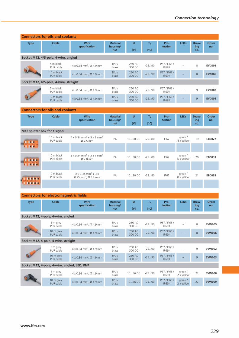
Connectors for oils and coolants
Type Cable Wirespecification
Materialhousing/
nut
U
[V]
Ta
[°C]
Pro-tection
LEDs Draw-ingno.
Orderno.
Socket M12, 4/5-pole, 4-wire, angled
5 m blackPUR cable 4 x 0.34 mm2, Ø 4.9 mm
TPU /brass
250 AC300 DC
-25...90IP67 / IP68 /
IP69K– 8 EVC005
10 m blackPUR cable 4 x 0.34 mm2, Ø 4.9 mm
TPU /brass
250 AC300 DC
-25...90IP67 / IP68 /
IP69K– 8 EVC006
Socket M12, 4/5-pole, 4-wire, straight
5 m blackPUR cable 4 x 0.34 mm2, Ø 4.9 mm
TPU /brass
250 AC300 DC
-25...90IP67 / IP68 /
IP69K– 9 EVC002
10 m blackPUR cable 4 x 0.34 mm2, Ø 4.9 mm
TPU /brass
250 AC300 DC
-25...90IP67 / IP68 /
IP69K– 9 EVC003
Connectors for oils and coolants
Type Cable Wirespecification
Materialhousing/
nut
U
[V]
Ta
[°C]
Pro-tection
LEDs Draw-ingno.
Orderno.
M12 splitter box for 1 signal
10 m blackPUR cable
4 x 0.34 mm2 + 3 x 1 mm2,Ø 7.5 mm
PA 10...30 DC -25...80 IP67green /
4 x yellow19 EBC027
10 m blackPUR cable
6 x 0.34 mm2 + 3 x 1 mm2,Ø 7.8 mm
PA 10...30 DC -25...80 IP67green /
6 x yellow20 EBC031
10 m blackPUR cable
8 x 0.34 mm2 + 3 x0.75 mm2, Ø 8.2 mm
PA 10...30 DC -25...80 IP67green /
8 x yellow21 EBC035
Connectors for electromagnetric fields
Type Cable Wirespecification
Materialhousing/
nut
U
[V]
Ta
[°C]
Pro-tection
LEDs Draw-ingno.
Orderno.
Socket M12, 4-pole, 4-wire, angled
5 m greyPUR cable 4 x 0.34 mm2, Ø 4.9 mm
TPU /brass
250 AC300 DC
-25...90IP67 / IP68 /
IP69K– 8 EVW005
10 m greyPUR cable 4 x 0.34 mm2, Ø 4.9 mm
TPU /brass
250 AC300 DC
-25...90IP67 / IP68 /
IP69K– 8 EVW006
Socket M12, 4-pole, 4-wire, straight
5 m greyPUR cable 4 x 0.34 mm2, Ø 4.9 mm
TPU /brass
250 AC300 DC
-25...90IP67 / IP68 /
IP69K– 9 EVW002
10 m greyPUR cable 4 x 0.34 mm2, Ø 4.9 mm
TPU /brass
250 AC300 DC
-25...90IP67 / IP68 /
IP69K– 9 EVW003
Socket M12, 4-pole, 4-wire, angled, LED, PNP
5 m greyPUR cable 4 x 0.34 mm2, Ø 4.9 mm
TPU /brass
10...36 DC -25...90IP67 / IP68 /
IP69Kgreen /
2 x yellow22 EVW008
10 m greyPUR cable 4 x 0.34 mm2, Ø 4.9 mm
TPU /brass
10...36 DC -25...90IP67 / IP68 /
IP69Kgreen /
2 x yellow22 EVW009
Connection technology
229www.ifm.com

Connectors for hygienic and wet areas
Type Cable Wirespecification
Materialhousing/
nut
U
[V]
Ta
[°C]
Pro-tection
LEDs Draw-ingno.
Orderno.
Socket M8, 3-pole, 3-wire, angled
5 m orangePVC cable 3 x 0.25 mm2, Ø 5 mm
PVC / st. steel316L / 1.4404
60 AC75 DC
-25...85 IP68 – 23 E11498
10 m orangePVC cable 3 x 0.25 mm2, Ø 5 mm
PVC / st. steel316L / 1.4404
60 AC75 DC
-25...85 IP68 – 23 E11499
Socket M8, 3-pole, 3-wire, straight
5 m orangePVC cable 3 x 0.25 mm2, Ø 5 mm
PVC / st. steel316L / 1.4404
60 AC75 DC
-25...85 IP68 – 24 E11495
10 m orangePVC cable 3 x 0.25 mm2, Ø 5 mm
PVC / st. steel316L / 1.4404
60 AC75 DC
-25...85 IP68 – 24 E11496
Socket M8, 4-pole, 4-wire, angled
5 m orangePVC cable 4 x 0.25 mm2, Ø 5 mm
PVC / st. steel316L / 1.4404
60 AC75 DC
-25...90 IP68 – 25 E11220
10 m orangePVC cable 4 x 0.25 mm2, Ø 5 mm
PVC / st. steel316L / 1.4404
60 AC75 DC
-25...90 IP68 – 25 E11221
Socket M8, 4-pole, 4-wire, straight
5 m orangePVC cable 4 x 0.25 mm2, Ø 5 mm
PVC / st. steel316L / 1.4404
60 AC75 DC
-25...90 IP68 – 26 E11223
10 m orangePVC cable 4 x 0.25 mm2, Ø 5 mm
PVC / st. steel316L / 1.4404
60 AC75 DC
-25...90 IP68 – 26 E11224
Socket M12, 4-pole, 4-wire, angled
5 m orangePVC cable 4 x 0.34 mm2, Ø 4.9 mm
PVC / st. steel316L / 1.4404
250 AC300 DC
-25...100IP67 / IP68 /
IP69K– 27 EVT004
10 m orangePVC cable 4 x 0.34 mm2, Ø 4.9 mm
PVC / st. steel316L / 1.4404
250 AC300 DC
-25...100IP67 / IP68 /
IP69K– 27 EVT005
Socket M12, 4-pole, 4-wire, straight
5 m orangePVC cable 4 x 0.34 mm2, Ø 4.9 mm
PVC / st. steel316L / 1.4404
250 AC300 DC
-25...100IP67 / IP68 /
IP69K– 28 EVT001
10 m orangePVC cable 4 x 0.34 mm2, Ø 4.9 mm
PVC / st. steel316L / 1.4404
250 AC300 DC
-25...100IP67 / IP68 /
IP69K– 28 EVT002
Socket M12, 4-pole, 4-wire, angled, LED, PNP
5 m orangePVC cable 4 x 0.34 mm2, Ø 4.9 mm
PVC / st. steel316L / 1.4404
10...36 DC -25...100IP67 / IP68 /
IP69Kgreen /
2 x yellow29 EVT007
10 m orangePVC cable 4 x 0.34 mm2, Ø 4.9 mm
PVC / st. steel316L / 1.4404
10...36 DC -25...100IP67 / IP68 /
IP69Kgreen /
2 x yellow29 EVT008
Jumper M12, 4-pole, 4-wire, straight / straight
0.3 m orangePVC cable 4 x 0.34 mm2, Ø 4.9 mm
PVC / st. steel316L / 1.4404
250 AC300 DC
-25...100IP67 / IP68 /
IP69K– 30 EVT040
0.6 m orangePVC cable 4 x 0.34 mm2, Ø 4.9 mm
PVC / st. steel316L / 1.4404
250 AC300 DC
-25...100IP67 / IP68 /
IP69K– 30 EVT041
1 m orangePVC cable 4 x 0.34 mm2, Ø 4.9 mm
PVC / st. steel316L / 1.4404
250 AC300 DC
-25...100IP67 / IP68 /
IP69K– 30 EVT042
2 m orangePVC cable 4 x 0.34 mm2, Ø 4.9 mm
PVC / st. steel316L / 1.4404
250 AC300 DC
-25...100IP67 / IP68 /
IP69K– 30 EVT043
5 m orangePVC cable 4 x 0.34 mm2, Ø 4.9 mm
PVC / st. steel316L / 1.4404
250 AC300 DC
-25...100IP67 / IP68 /
IP69K– 30 EVT044
Socket M12, 5-pole, 5-wire, angled
5 m orangePVC cable 5 x 0.34 mm2, Ø 5.1 mm
PVC / st. steel316L / 1.4404
30 AC36 DC
-25...100IP67 / IP68 /
IP69K– 31 EVT013
Connection technology
230www.ifm.com
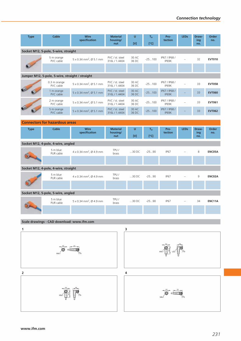
Type Cable Wirespecification
Materialhousing/
nut
U
[V]
Ta
[°C]
Pro-tection
LEDs Draw-ingno.
Orderno.
Socket M12, 5-pole, 5-wire, straight
5 m orangePVC cable 5 x 0.34 mm2, Ø 5.1 mm
PVC / st. steel316L / 1.4404
30 AC36 DC
-25...100IP67 / IP68 /
IP69K– 32 EVT010
Jumper M12, 5-pole, 5-wire, straight / straight
0.3 m orangePVC cable 5 x 0.34 mm2, Ø 5.1 mm
PVC / st. steel316L / 1.4404
30 AC36 DC
-25...100IP67 / IP68 /
IP69K– 33 EVT058
1 m orangePVC cable 5 x 0.34 mm2, Ø 5.1 mm
PVC / st. steel316L / 1.4404
30 AC36 DC
-25...100IP67 / IP68 /
IP69K– 33 EVT060
2 m orangePVC cable 5 x 0.34 mm2, Ø 5.1 mm
PVC / st. steel316L / 1.4404
30 AC36 DC
-25...100IP67 / IP68 /
IP69K– 33 EVT061
5 m orangePVC cable 5 x 0.34 mm2, Ø 5.1 mm
PVC / st. steel316L / 1.4404
30 AC36 DC
-25...100IP67 / IP68 /
IP69K– 33 EVT062
Connectors for hazardous areas
Type Cable Wirespecification
Materialhousing/
nut
U
[V]
Ta
[°C]
Pro-tection
LEDs Draw-ingno.
Orderno.
Socket M12, 4-pole, 4-wire, angled
5 m bluePUR cable 4 x 0.34 mm2, Ø 4.9 mm
TPU /brass
...30 DC -25...90 IP67 – 8 ENC05A
Socket M12, 4-pole, 4-wire, straight
5 m bluePUR cable 4 x 0.34 mm2, Ø 4.9 mm
TPU /brass
...30 DC -25...90 IP67 – 9 ENC02A
Socket M12, 5-pole, 5-wire, angled
5 m bluePUR cable 5 x 0.34 mm2, Ø 4.9 mm
TPU /brass
...30 DC -25...90 IP67 – 34 ENC11A
Scale drawings - CAD download: www.ifm.com
1
9
10 31
M8x1
2
9
10 19
M8x1 25,5
3
9
10 19
M8x1 25,5
LED
4
9
10 31
M8x1
Connection technology
231www.ifm.com

Scale drawings - CAD download: www.ifm.com
5
9
10 19
M8x1 25,5
6
35
18
20
M12 x1
30
7
18
M12 x1
46
8
15,5
M12x1 36,5
26,5
14
9
15,5
M12x1 45
14
10
43
15
M12 x1
11
15
38
M12 x1
28
10,5
12
4520
M16x1
49
13
27
10,5
15
39
G 21
14
42
10,5
15
G 21
15
27
10,5
15
39
"-20UNF21
16
42
18
15
20
M12 x1
31
Connection technology
232www.ifm.com

Scale drawings - CAD download: www.ifm.com
17
5220
M12 x1
18
15,5
M12x1 49,5
14
19
1 2
43PWR
18224,
773
118,
234
55
4,5
28,539
7,5
60
M12x1
20
1 2
4
6
3
5
PWR
18224,
773
125
34
55
4,5
28,539
7,5
60
M12x1
21
1 2
4
6
8
3
5
7
PWR
18224,
773
152
34
55
4,5
28,539
7,5
60
M12x1
22
15,5
M12x1 36,5
26,5
143 LED
23
18
9
28
M8 x1
10
24
10
M8 x1
31
9
25
18
9
28
M8 x1
10
Connection technology
233www.ifm.com
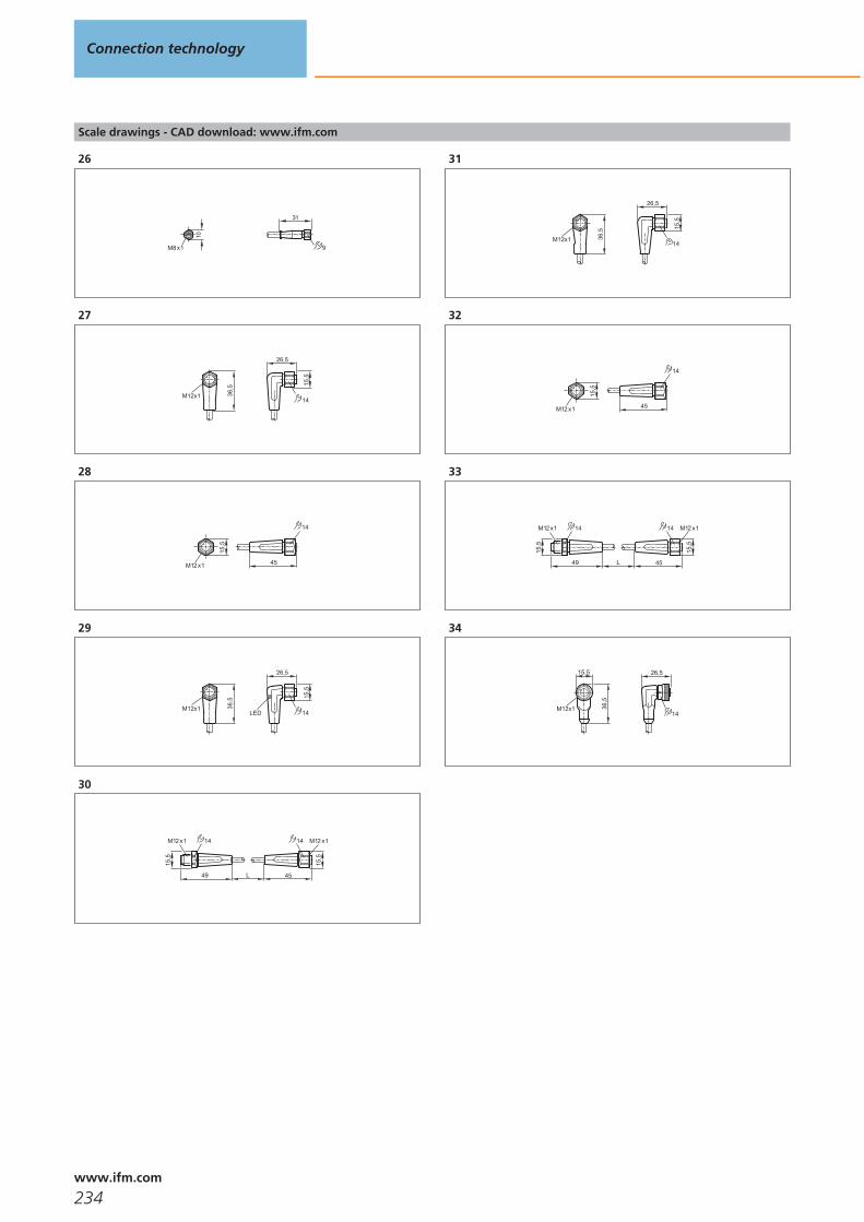
Scale drawings - CAD download: www.ifm.com
26
10
M8 x1
31
9
2715
,5
M12x1 36,5
26,5
14
28
15,5
45
14
M12 x1
29
15,5
M12x1 36,5
26,5
14LED
30
L
15,5
M12 x1
49
14
45
15,5
M12 x1 14
31
15,5
M12x1 36,5
26,5
14
32
15,5
45
14
M12 x1
33
L
15,5
M12 x1
49
14
45
15,5
M12 x1 14
34
15,5
M12x1 36,5
26,5
14
Connection technology
234www.ifm.com

Connection technology
235

ifm – worldwideaddresses
236www.ifm.com
Argentinaifm electronic s.r.l.Manuela Sáenz 3235º piso, oficina 3C1107BPA - Puerto MaderoBuenos Aires, ArgentinaTel. (011) 5353-3436Fax (011) 5353-3436Interior [email protected]/ar
Australiaifm efector pty ltd.P.O. Box 4084Suite 3, 745 Springvale RoadMulgrave VIC 3170Tel. 1300 365 088Fax 1300 365 [email protected]
Austriaifm electronic gmbhWienerbergstraße 41Gebäude E1120 ViennaTel. +43 / 1 / 617 45 00Fax +43 / 1 / 617 45 00 [email protected]/at
BangladeshSensotec AutomationRed Crescent Chamber87, Motijheel CommercialAreaDhaka 1000BangladeshTel. +880 171 546 [email protected]
BelarusDEPOSIT INVESTJoint-Stock CompanyBlock 2, 27 Zheleznodorovhnaya street220089 MinskRepublic of BelarusTel. +375-17-270 75 06Fax +375-17-270 75 [email protected]
Belgium andLuxembourgifm electronic n.v./s.a.Zuiderlaan 911731 ZellikBelgiëTel. +32 2 481 0220Fax +32 2 463 [email protected]/be
BoliviaBAVARIA S.R.L.Álvaro Baptista VargasZona Morocollo, Urb. SantosPariamoC. Mario Diaz de medina (26-A), Nr. 32La Paz - BoliviaTel.: 00-591-2-277 13 78Mobile: 00-591-720-47 [email protected]
Brazilifm electronic Ltda.Rua Eleonora Cintra, 140Jardim Analia Franco03337-000 São Paulo/SPTel. +55-11-2672-1730Fax [email protected]/br
Bulgariaifm electronic eoodul. Slatinska Nr. 92 A, ap. 2/31574 SOFIATel. +359 2 807 59 69Fax. +359 2 807 59 [email protected]
Canadaifm efector Canada Inc. 700 Dorval Drive/CorporateCentreOakville; L6K3V3 OntarioTel. +1-800-441-8246 Fax [email protected]
ChileElectronica IndustrialSchädler y Cia. Ltda.Av. Antonio Varas 1871Providencia6641545 SantiagoTel. +56 / 2 / 274 74 30Fax +56 / 2 / 204 93 [email protected]
Chinaifm electronic (Shanghai)Co., LtdBuilding 15, No 912Bi Bo Road, Pu Dong DistrictShanghai 201210, ChinaTel. +86-21-50278559 Fax +86-21-50278669Fax [email protected] www.ifm.com/cnifm electronic (HK) LtdUnit 2106, 21/F, Tower 2, MetroplazaNo. 223 Hing Fong Road, Kwai Chung, N.T., Hong Kong.Telefon: +852 3528-0462Fax: +852 [email protected]/hkifm electronic (Taiwan)Limited2C, Bao-Cheng EnterpriseTower,No. 6 Mincyuan Second Road,Cianjhen District, KaohsiungCity,Postal Code 806, Taiwan,R.O.C.Tel.: +886-7-335-7778Fax: [email protected]/tw
ColumbiaSENSOMATIC Y CIA LTDA.CALLE 1 C 25a - 50BOGOTA D.C. COLOMBIATel. +57 313 430 2264and +57 1 407 96 [email protected]://www.sensomatic-ltda.com
Croatiaifm electronic gmbhWienerbergstr. 41Gebäude EA-1120 WienTel. +43 / 1 / 617 45 00Fax +43 / 1 / 617 45 00 [email protected]/hr
Czech Republicifm electronic spol.s.r.o.U Křížku 571252 43 PragueTel. +420 / 2 / 67 990 211 Fax +420 / 2 / 67 750 180 [email protected]/cz
Denmarkifm electronic a/sRingager 4A, 1.sal tv.2605 BrøndbyTel. +45 70 20 11 08Fax +45 70 20 11 [email protected]/dk
Dominican RepublicWECH AUTOCONTROLES S. A.Ave. Romulo Betancourt 2158 Edificio WechUrb. RenacimientoSanto DomingoDominican RepublicTel.: + 1 809-531-0550Fax: + 1 [email protected]
EcuadorINSELEC CIA. LTDA.Av. de los AruposE1-202 y Pan. Norte- Km 5 ½QuitoTel. +593 2 28074- 76 - 78Fax +593 2 [email protected]
EgyptEgyptian Establishment forElectromechanical SuppliesMr. Ahmed Gouda27 Al-Salam StreetAl Arezona, Al Haram RoadGiza 12111, CairoTel. +20 / 2 / 586 49 49Fax +20 / 2 / 586 49 49Mobile +20 10 10 61 [email protected]
EstoniaPesmel Estonia LTDSegu 476505 SaueEstoniaTel.: +372 674 73 30 Fax: +372 674 73 [email protected]
Finlandifm electronic oyVaakatie 5 00440 Helsinki Tel. +358 / 9 / 751 777 00 Fax +358 / 9 / 751 777 10 [email protected]/fi
Franceifm electronicSiège :Savoie Technolac BP22673374 Le Bourget du LacAgence commerciale :Immeuble Uranus1-3 rue Jean Richepin93192 NOISY LE GRANDCEDEXTél: 0820 22 30 01Fax: 0820 22 22 [email protected]/fr
Germanyifm electronic gmbhFriedrichstr. 145128 EssenTel. +49 201 24 22 0Fax +49 201 24 22 12 [email protected]/de
Greeceifm electronic monoprosopiE.P.E.27, Andrea Papandreou Street15125 AmaroussiGreeceTel +30 210 61 800 90Fax +30 210 61 994 [email protected]/gr
HondurasR y D INDUSTRIALBo. Paz Barahona11 Ave. 14 y 15 CalleS.O. #142San Pedro SulaTelefon:+504 5503703Telefax:+504 [email protected]
Hungaryifm electronic kft.Közép u. 16. II.em. 208. irodaH-9024 GyőrTel. +36-96 / 518-397Fax +36-96 / [email protected]/hu
Indiaifm electronic India Pvt. Ltd.Plot No. P-39/1MIDC Gokul ShirgaonKolhapur – 416234Maharashtra State, IndiaTel. +91 / 231 / 267 27 70Fax +91 / 231 / 267 23 [email protected]/in
IndonesiaPT Indoserako SejahteraJl. P. Jayakarta 121 No. 5910730 Jakarta PusatTel. +62 / 21 6 24 8923Fax +62 / 21 6 24 [email protected]
Irelandifm electronic (Ireland) Ltd.No. 7, The CourtyardKilcarbery Business ParkNew Nangor RoadClondalkinDublin 22Tel. +353 / 1 / 413 60 66Fax +353 / 1 / 457 38 [email protected]/ie
IsraelAstragal Ltd.3, Hashikma Str.Azur 58001P.O. Box 99Azur 58190Tel. +972 / 3 / 5 59 16 60Fax +972 / 3 / 5 59 23 [email protected]
Italyifm electronicCentro Direzionale ColleoniPalazzo Andromeda 2Via Paracelo n° 1820041 Agrate Brianza (Milano)Tel. +39 / 039 68 99 982Fax +39 / 039 68 99 [email protected]/it
Japanefector co. ltd.Chiba Higashi Techno Green Park2-9-20 OkayamadaiTogane-shi, Chiba 283-0826Tel. +81 / 475 50 3003Fax +81 / 475 50 [email protected]/jp
JordanAl Mashreqan Trading SuppliesP.O.Box.85105411185 SwaifiehAmman - Jordan.Tel. +962 6 581 8841Fax +962 6 581 [email protected]
Koreaifm electronic Ltd.2F Hyundai Liberty House#201Hannam-Dong 258,Yongsan-Gu,Seoul, KoreaTel +82 2-790-5610Fax +82 [email protected]/kr
LatviaEC SystemsKatlakalna Str. 4A1073 RigaLatviaTel.: +371 724 1231Fax: +371 724 [email protected]
ifm – worldwideaddresses
237www.ifm.com
LebanonMiddle East DevelopmentCo. SAL (MEDEVCO)Medevco Building Jeita Main Road Jeita - Kesrouan LebanonMail address :P.O.Box 67 Jounieh LebanonTel + 961-9-233550 Fax + 961-9-233554 [email protected]
LithuaniaElinta UABTerminalo g. 3, Biruliškių k.,Karmėlavos sen.LT-54469 Kauno raj. (Kauno LEZ)LithuaniaTel.: +370 37 351 999Fax: +370 37 452 [email protected]
Malaysiaifm electronic Pte. LtdMalaysian Branch OfficeNo. 2-4-2, Fourth FloorTower 2 @ PFCC, Jalan Puteri 1/2,Bandar Puteri Puchong,47100 Puchong, Selangor.Tel. +60 / 3 / 8063 9522Fax +60 / 3 / 8063 [email protected] electronicAsia Regional OfficeNo. 21, Jalan Kemunting,Taman Kebun The80250 Johor BahruJohor, West MalaysiaTel. +60 / 7 / 332 5022Fax +60 / 7 / 332 [email protected]
Mexicoifm efector S. de R.L. de C.V.Anillo Periférico, 1816-1Col. Hacienda San JerónimoMonterrey, N.L.Mexico 64630Tel. +52-81-8040-3535Fax +52-81-8040-2343www.ifmefector.mx
Netherlandsifm electronic b.v.Deventerweg 1 E3843 GA HarderwijkTel. +31 / 341 438 438Fax +31 / 341 438 [email protected]/nl
New Zealandifm efector pty ltd.Unit B, 20 Cain RoadPenrose, AucklandTel. +64 / 95 79 69 91Fax +64 / 95 79 92 [email protected]/nz
NigeriaAutomated Process Ltd3rd Floor, 32 Lagos AbeokutaExpresswayNear Cement Bus StopDopemu, AgegeLagos State, NigeriaTel. + 234 / 01 / 4729 967Fax + 234 /01 / 4925 [email protected]
NorwaySiv.Ing. J.F.Knudtzen ASBillingstadsletta 971396 BillingstadPostboks 1601378 NesbruTel. +47 / 66 98 33 50Fax +47 / 66 98 09 [email protected]
OmanTechnical Engineering Company LLC.P.O.Box. 59 Madinat Al Sultan QaboosPostal Code 115 Sultanate of OmanTel + 968 24503593Fax + 968 [email protected]
PakistanAB AutomationShop No.2. Rubab ChamberM.A. Jinnah RoadOff Sarai RoadKarachiTel. +92 / 21 / 2412 278Fax +92 / 21 / 2422 [email protected]
Perudekatec s.a.c.Los Calderos 188Urb. Vulcano, AteLima / PeruTel. +511 / 348 0293Tel. +511 / 348 0458Tel. +511 / 348 2269Fax +511 / 349 [email protected]
PhilippinesGram Industrial, Inc.Unit 410 Common GoalTowerFinance cor. Industry St.,Madrigal Business Park,Ayala Alabang, MuntinlupaCity1770 Philipines Tel. (+63) 2 850-2218Fax (+63) 2 [email protected]
Polandifm electronic Sp.z o.o.ul. Kosciuszki 175PL 40-524 KatowiceTel. +48 / 32 / 60 87 454Fax +48 / 32 / 60 87 [email protected]/pl
Portugalifm electronic –Sucursal em PortugalAvenida da Republica 25034430-208 Vila Nova de GaiaTel. +351 / 22 / 37 17 108Fax +351 / 22 / 37 17 [email protected]/pt
Romaniaifm electronic s.r.l.Str. Cristian Nr. 5550073 SibiuTel.: 0040 269 224550Fax: 0040 269 [email protected]
Russiaifm electronicIbragimova, 31, k.50office 607105318 MoscowTel.: +7 (495) 921-44-14Fax: +7 (495) [email protected]/ru
Saudi ArabiaNoor Al-Shomoe for Electric& MaintenanceKing Khalid Street, Cross 5P.O. Box 2571Al-Khobar 31952Kingdom of Saudi ArabiaTel. +9 663 864 49 58Fax +9 663 894 63 [email protected]
Singaporeifm electronic Pte. Ltd.25, Intern. Business Park#03-104 German Center609 916 SingaporeTel. +65 / 6 / 5 62 86 61Fax +65 / 6 / 5 62 86 [email protected]/sg
Slovakiaifm electronic spol. s.r.o.Rybnicna 40831 06 BratislavaTel. +421 / 2 / 44 87 23 29Fax +421 / 2 / 44 64 60 [email protected]/sk
South Africaifm electronic (pty) LtdShorrok HouseRoute 21 Corporate ParkNellmapius Drive, Irene Ext. 30, Centurion 0157, Pretoria Postnet Suite 279Private bag X8Elardus Park0047Tel. +27 (0) 861 IFM RSA /436 772Fax +27(0)12 450 [email protected]/za
Spainifm electronic s.l.Edificio Prima Muntadas AParc Mas BlauC/Berguedà 108820 El Prat de LlobregatTel. +34 / 93 / 479 30 80Fax +34 / 93 / 479 30 [email protected]/es
Swedenifm electronic abHallavägen 10 512 60 Överlida Office Gothenburg:Drakegatan 641250 GothenburgTel. +46 / 325 / 66 15 00 Tel. +46 / 325 / 66 15 50Fax +46 / 325 / 66 15 [email protected]/se
Switzerlandifm electronic agAltgraben 274624 HärkingenTel. +41 / 62 / 388 80 30Fax +41 / 62 / 388 80 [email protected]/ch
SyriaI.E.C. Industrial EngineeringCenterP.O. Box 15 Sehnaya, DamascusSyriaTel. + 963 11 532 13 19Fax. + 963 11 442 12 [email protected]
ThailandSang Chai Meter Co., Ltd.694/16-19 Phaholyothin RoadSamsen Nai, Phayathai Bangkok 10400 Tel. +66 / 2 / 616 8051Fax +66 / 2 / 616 [email protected]
Turkeyifm electronic Elektrikli ve Elektronik Aletlerİth.İhr.Paz.Tic.Ltd.Şti. Merkez Mah. Nadide Sok. Anıttepe Sitesi No:28 34381 Şişli / İstanbulTel. +90 / 212 / 210 5080Fax +90 / 212 / 221 [email protected]/tr
Ukrainaifm electronicMariny Raskovoj 1102660 KievUkraineTel. +380 44 501 8543Fax +380 44 501 [email protected]/ua
United Arab EmiratesNoor Al-Shomoe ElectricalEquipments Est.P.O.Box. 64052Unit no. 36Reef Real EstateJebel Ali Industrial Area no. 3DubaiUnited Arab EmiratesTel.. + 971 4 880 3838Fax.+ 971 4 880 3883Mobile: + 971 [email protected] Arab Emirates –Abu DhabiAl Injazat Technical Trading ServicesP.O. Box 42895Abu DhabiUnited Arab EmiratesTel. +971 2 622 6030Fax +971 2 622 [email protected]
United Kingdomifm electronic Ltd.efector HouseKingsway Business ParkOldfield RoadHamptonMiddlesex TW12 2HDTel. +44 / 20 / 8213 0000Fax +44 / 20 / 8213 [email protected]/uk
USAefector inc.805 Springdale Drive Exton, PA 19341 Tel. +1 / 610 524 2000 Fax +1 / 610 524 [email protected]
VenezuelaPetrobornas, C.A.C.C. Los Pinos - Local EAv. Principal de la UD 304(8015) - Puerto Ordaz - Edo.BolivarVenezuelaTel. +58 286 994 3406Tel. +58 416 686 5036Fax +58 286 994 [email protected]
VietnamThien Viet Electrical Serviceand Trading Co., Ltd.784 Dien Bien Phu Str.Ward 11, Dist. 10Ho-Chi-Minh-City, Viet NamTel. +84 / 8 / 830 9916 Fax +84 / 8 / 830 [email protected]

www.ifm.com