IEEE TRANSACTIONS ON MICROWAVE THEORY AND …klwu/pdf/mtt201606.pdf · IEEE TRANSACTIONS ON...
11
IEEE TRANSACTIONS ON MICROWAVE THEORY AND TECHNIQUES, VOL. 64, NO. 6, JUNE 2016 1787 Model-Based Vector-Fitting Method for Circuit Model Extraction of Coupled-Resonator Diplexers Ping Zhao, Student Member, IEEE, and Ke-Li Wu, Fellow, IEEE Abstract—In this paper, a novel rational function approxi- mation method, namely, model-based vector fitting (MVF), is proposed for accurate extraction of the characteristic functions of a coupled-resonator diplexer with a resonant type of junction from noise-contaminated measurement data. MVF inherits all the merits of the vector-fitting (VF) method and can also stipulate the order of the numerator of the model. Thus, MVF is suitable for the high-order diplexer system identification problem against measurement noise. With the extracted characteristic functions, a three-port transversal coupling matrix of a diplexer can be synthesized. A matrix orthogonal transformation strategy is also proposed to transform the obtained transversal matrix to a target coupling matrix configuration, whose entries have one-to-one relationship with the physical tuning elements. The whole model extraction procedure is analytical and robust, and can be used in a computer-aided tuning (CAT) program for coupled-resonator diplexers. A practical tuning example of a diplexer with a com- mon resonator is given in detail to demonstrate the effectiveness and the practical value of the proposed method. Index Terms—Computer-aided tuning (CAT), coupling matrix, microwave diplexer, rational approximation, vector fitting (VF). I. I NTRODUCTION C OUPLED resonator networks are commonly utilized as frequency-selective devices in RF and microwave passive circuits such as filters, diplexers, and multiplexers, and play very important roles in modern communication systems. It is well known that the transfer and reflection characteristics of a coupled-resonator network can be described by a set of rational functions [1]. The concept has been successfully applied not only to the design of bandpass filters, but also other functional microwave networks such as power dividers [2], diplexers [3], multiple-input multiple-output (MIMO) antenna decoupling networks [4], and nonreciprocal networks [5]. There are var- ious ways to implement a coupled-resonator network: cou- pled waveguide resonant cavities, coupled coaxial combline resonators, and coupled dielectric resonators of multiple modes are commonly seen in today’s communication systems. Manuscript received October 16, 2015; revised March 31, 2016; accepted April 21, 2016. Date of publication May 9, 2016; date of current version June 2, 2016. This work was supported by The Chinese University of Hong Kong under a Postgraduate Scholarship. This work was supported in part by the Development and Reform Commission of Shenzhen Municipality under Grant Shen Fa Gai (2013) 1673. The authors are with the Department of Electronic Engineering and the Shenzhen Engineering Laboratory of Wireless Locating Technology and Systems, Shenzhen Research Institute, The Chinese University of Hong Kong, Shatin, Hong Kong (e-mail: [email protected]; [email protected]). Color versions of one or more of the figures in this paper are available online at http://ieeexplore.ieee.org. Digital Object Identifier 10.1109/TMTT.2016.2558639 In mass production of such microwave devices, the physical realization is highly sensitive to the dimensional tolerance of the resonators as well as the coupling elements. Therefore, manual tuning is necessary in the production process to meet the stringent system specifications. Traditionally, the tuning is accomplished by skilled technologists through consecutive manual adjustments based on their years of accumulated experience. Tuning a coupled-resonator device with a complex coupling topology is a demanding, time-consuming, and costly process. A computer-aided tuning (CAT) tool that can identify those unsatisfying coupling values and deterministically guide the tuning process is highly appreciated in the microwave industry. With such a CAT tool, the tuning process will depend much less on human experience and the cost of the production can be greatly reduced. Up to now the majority of research efforts devoted to CAT algorithms are for bandpass filters [6]–[11]. With the measured (or electromagnetic (EM) simulation) results of the device, the circuit model that corresponds to the current tuning state is extracted, which is then compared with the designed circuit model to suggest the tuning direction and amount for the next tuning step. Obviously, the most critical and difficult part in the CAT procedure is the extraction of the circuit model from measured data. Although this task can be undertaken by optimization techniques [7], such approaches are time consuming and heavily depend on a set of good initial values. It is much more difficult to analytically extract the circuit model of a diplexer than that of a filter for three major reasons. First, the interaction between the two channel filters makes the diplexer a high-order system. The traditional rational function approxi- mation method, like the Cauchy method, has the problem of ill conditioning when it is used to deal with high-order systems. Second, to meet the stringent requirement of Tx and Rx iso- lation, complex coupling topologies are commonly seen in a diplexer introducing finite-position transmission zeroes (TZs) to improve the isolation. As a result, how to obtain the circuit model, which can give the identical response with the device and has the same coupling structure, is a challenging problem. Third, the measured frequency response of the diplexer is inevitably contaminated by measurement noise, and the iso- lation characteristics can be completely buried by the noise floor. Although there are some discussions on diplexer circuit model extraction in the literature [12], no practical application has yet been presented. 0018-9480 © 2016 IEEE. Personal use is permitted, but republication/redistribution requires IEEE permission. See http://www.ieee.org/publications_standards/publications/rights/index.html for more information.
Transcript of IEEE TRANSACTIONS ON MICROWAVE THEORY AND …klwu/pdf/mtt201606.pdf · IEEE TRANSACTIONS ON...

IEEE TRANSACTIONS ON MICROWAVE THEORY AND TECHNIQUES, VOL. 64, NO. 6, JUNE 2016 1787
Model-Based Vector-Fitting Methodfor Circuit Model Extraction ofCoupled-Resonator Diplexers
Ping Zhao, Student Member, IEEE, and Ke-Li Wu, Fellow, IEEE
Abstract— In this paper, a novel rational function approxi-mation method, namely, model-based vector fitting (MVF), isproposed for accurate extraction of the characteristic functionsof a coupled-resonator diplexer with a resonant type of junctionfrom noise-contaminated measurement data. MVF inherits all themerits of the vector-fitting (VF) method and can also stipulatethe order of the numerator of the model. Thus, MVF is suitablefor the high-order diplexer system identification problem againstmeasurement noise. With the extracted characteristic functions,a three-port transversal coupling matrix of a diplexer can besynthesized. A matrix orthogonal transformation strategy is alsoproposed to transform the obtained transversal matrix to a targetcoupling matrix configuration, whose entries have one-to-onerelationship with the physical tuning elements. The whole modelextraction procedure is analytical and robust, and can be used ina computer-aided tuning (CAT) program for coupled-resonatordiplexers. A practical tuning example of a diplexer with a com-mon resonator is given in detail to demonstrate the effectivenessand the practical value of the proposed method.
Index Terms— Computer-aided tuning (CAT), coupling matrix,microwave diplexer, rational approximation, vector fitting (VF).
I. INTRODUCTION
COUPLED resonator networks are commonly utilized asfrequency-selective devices in RF and microwave passive
circuits such as filters, diplexers, and multiplexers, and playvery important roles in modern communication systems. It iswell known that the transfer and reflection characteristics of acoupled-resonator network can be described by a set of rationalfunctions [1]. The concept has been successfully applied notonly to the design of bandpass filters, but also other functionalmicrowave networks such as power dividers [2], diplexers [3],multiple-input multiple-output (MIMO) antenna decouplingnetworks [4], and nonreciprocal networks [5]. There are var-ious ways to implement a coupled-resonator network: cou-pled waveguide resonant cavities, coupled coaxial comblineresonators, and coupled dielectric resonators of multiplemodes are commonly seen in today’s communication systems.
Manuscript received October 16, 2015; revised March 31, 2016; acceptedApril 21, 2016. Date of publication May 9, 2016; date of current versionJune 2, 2016. This work was supported by The Chinese University ofHong Kong under a Postgraduate Scholarship. This work was supported inpart by the Development and Reform Commission of Shenzhen Municipalityunder Grant Shen Fa Gai (2013) 1673.
The authors are with the Department of Electronic Engineering and theShenzhen Engineering Laboratory of Wireless Locating Technology andSystems, Shenzhen Research Institute, The Chinese University of Hong Kong,Shatin, Hong Kong (e-mail: [email protected]; [email protected]).
Color versions of one or more of the figures in this paper are availableonline at http://ieeexplore.ieee.org.
Digital Object Identifier 10.1109/TMTT.2016.2558639
In mass production of such microwave devices, the physicalrealization is highly sensitive to the dimensional tolerance ofthe resonators as well as the coupling elements. Therefore,manual tuning is necessary in the production process to meetthe stringent system specifications. Traditionally, the tuningis accomplished by skilled technologists through consecutivemanual adjustments based on their years of accumulatedexperience. Tuning a coupled-resonator device with a complexcoupling topology is a demanding, time-consuming, and costlyprocess. A computer-aided tuning (CAT) tool that can identifythose unsatisfying coupling values and deterministically guidethe tuning process is highly appreciated in the microwaveindustry. With such a CAT tool, the tuning process will dependmuch less on human experience and the cost of the productioncan be greatly reduced.
Up to now the majority of research efforts devoted to CATalgorithms are for bandpass filters [6]–[11]. With the measured(or electromagnetic (EM) simulation) results of the device, thecircuit model that corresponds to the current tuning state isextracted, which is then compared with the designed circuitmodel to suggest the tuning direction and amount for the nexttuning step.
Obviously, the most critical and difficult part in the CATprocedure is the extraction of the circuit model from measureddata. Although this task can be undertaken by optimizationtechniques [7], such approaches are time consuming andheavily depend on a set of good initial values. It is muchmore difficult to analytically extract the circuit model of adiplexer than that of a filter for three major reasons. First, theinteraction between the two channel filters makes the diplexera high-order system. The traditional rational function approxi-mation method, like the Cauchy method, has the problem of illconditioning when it is used to deal with high-order systems.Second, to meet the stringent requirement of Tx and Rx iso-lation, complex coupling topologies are commonly seen in adiplexer introducing finite-position transmission zeroes (TZs)to improve the isolation. As a result, how to obtain the circuitmodel, which can give the identical response with the deviceand has the same coupling structure, is a challenging problem.Third, the measured frequency response of the diplexer isinevitably contaminated by measurement noise, and the iso-lation characteristics can be completely buried by the noisefloor. Although there are some discussions on diplexer circuitmodel extraction in the literature [12], no practical applicationhas yet been presented.
0018-9480 © 2016 IEEE. Personal use is permitted, but republication/redistribution requires IEEE permission.See http://www.ieee.org/publications_standards/publications/rights/index.html for more information.

1788 IEEE TRANSACTIONS ON MICROWAVE THEORY AND TECHNIQUES, VOL. 64, NO. 6, JUNE 2016
Fig. 1. Complete circuit model that corresponds to practical measurementor EM simulation of a general three-port coupled-resonator network.
To address the mentioned issues, a new rational func-tion approximation method called the model-based vectorfitting (MVF) is proposed in [13]. This paper is a substantialextension of [13] where several issues related to the implemen-tation of MVF, including the selection of initial poles and theiterative pole relocation procedure, are further elaborated uponin this paper. Additionally, the details of how to synthesize thethree-port transversal coupling matrix from the obtained ratio-nal functions are explained. A novel similarity transformationstrategy is also proposed in this paper, which reconfigures thetransversal coupling matrix to the right matrix configuration.The strategy can be generalized to be suitable for other star-junction diplexers with common resonant nodes.
The basic theory on the multi-port coupled-resonator net-work underlying the circuit model extraction method is brieflyintroduced first. The MVF method is then proposed for fittingthe characteristic functions of the coupled-resonator diplexer,which evolves from the original vector-fitting (VF) techniqueand solves the “over-fitting” and “under-fitting” problemswith the VF approach. By introducing a set of pole-locatedmonomials as the basis functions, MVF enjoys the merits ofthe traditional Cauchy method, by which the order of thenumerator of a rational function can be stipulated in the fittingprocedure and the VF method, by which the conditioningof the system equations is better and the accuracy of thefitting is improved by the iterative pole relocation procedure.How a three-port transversal coupling matrix is synthesizedfrom the poles and residues determined in MVF is described,and then the transversal matrix is reconfigured to the rightform following a sequence of similarity transformations. Themeasured data of several tuning states of a coupled-resonatordiplexer with a common resonator are used to illustrate thecomplete circuit model extraction procedure. It can be seenthat the extracted circuit model with the method proposed inthis paper can capture very subtle adjustment made to thephysical tuning elements, which validates the robustness andthe practical value of the proposed method.
II. ADMITTANCE MATRIX OF A COUPLED
RESONATOR DIPLEXER
A. De-Embedding of the Phase Offset
For any practical measurement or EM simulation setup of acoupled-resonator diplexer, the proper circuit model that canrepresent the entire system is depicted in Fig. 1. As discoveredin [9], there is a constant phase loading θx that results fromthe high-order modes associated with I/O coupling at eachport. Besides, a piece of transmission line lx is there for
Fig. 2. (a) Phases of S11, S22, and S33 of the raw measured data. (b) Phasesof S11, S22, and S33 after removing the phase loading and de-embedding thetransmission line at each port.
connection of the device in practical measurement setup, orfor extending and clearly defining the port in EM simulation.The center block of Fig. 1 is the body of the diplexercomposed of coupled resonators, which can be described bya three-port coupling matrix M. In [9], the phase loadingeffect and the transmission line are removed by observingthe asymptotic phase response of each reflection coefficientbeyond the passband. For example, Fig. 2(a) shows the phasesof the measured reflection coefficients from one of the tuningstates of the testing diplexer shown in Fig. 3(a) with respectto the normalized low-pass domain angular frequency vari-able, and Fig. 2(b) shows the phases after phase loading andtransmission lines are de-embedded, where the phases of thereflection coefficients approach zero as s approaches infinity.Correct removal of the phase offset is crucial for identifyingthe true poles and zeroes of the Y -parameters.
B. Multi-Port Coupling Matrix
After the phase offset at each port is de-embedded, theS-parameters are then converted to Y -parameters numericallywith respect to unitary reference admittance at all ports. TheY -parameters are then consistent with the short-circuit admit-tance characteristics of a coupled-resonator circuit model withJ -inverters as the leading elements at all port. A multi-portcoupled-resonator network can be described by a coupling

ZHAO AND WU: MVF METHOD FOR CIRCUIT MODEL EXTRACTION OF COUPLED-RESONATOR DIPLEXERS 1789
Fig. 3. (a) Photograph of the testing diplexer. (b) Routing diagram of thetesting diplexer. Circles marked P1–P3 represent the three ports and the othercircles represent resonators. Solid straight lines are either mutual couplingsbetween resonators or I/O couplings.
matrix in the form of block matrices as
M =[
Mp Mpn
MTpn Mn
](1)
where Mp is a p-by-p sub-matrix consisting of direct cou-plings between the p ports, Mn is an n-by-n sub-matrix con-taining all the mutual couplings between the n resonators andthe self-couplings of resonators, Mpn is a p-by-n sub-matrixholding all the I/O couplings, and superscript T denotes thematrix transpose. The relationship between the Y -parametersand M is found to be [14]
Y = jMp + Mpn(sIn + jMn)−1MT
pn
= jMp +n∑
k=1
1
s + jMn(k, k)Mpn(:, k)Mpn(:, k)T (2)
where Mpn(:, k) denotes the kth column vector in thematrix Mpn . From (2), two basic properties can be observed:1) the elements in the Y -parameters share a set of commonpoles and 2) the residue matrix is symmetric and is of rankone. The second property is called the compactness of theresidues.
To correctly restore the coupling matrix of a diplexer,the above-mentioned two properties must be satisfied bythe Y -parameter rational functions. The first property canbe enforced during the rational fitting procedure, as willbe demonstrated in Section III. The second condition willnot be implemented since otherwise quadratic constraints areinvolved and nonlinear optimization techniques are needed tosolve the problem. However, in applying the MVF techniqueto the measured data of a physical coupled-resonator network,the residues obtained by the rational function approximationprocedure to be discussed next always well satisfy the second
property with very small numerical errors, provided that thephase offset at each port has been correctly de-embedded.Thus, a transversal coupling matrix can still be synthesized,which will be discussed in Section IV.
III. MVF FORMULATION
To explain the circuit model extraction procedure, measureddata of the coaxial resonator diplexer shown in Fig. 3(a)are used. The diplexer is introduced in [15], whose lowerfrequency band is 2.478–2.568 GHz, and upper frequencyband is 2.620–2.718 GHz. The routing diagram of the diplexeris shown in Fig. 3(b), where hollow circles with numbersinside represent resonators and the solid straight lines representcouplings. The two channel filters both consist of five res-onators, and resonator No. 6 constitutes a resonant type ofjunction.
Once the measured data are obtained, the physical frequencyis mapped to the low-pass frequency domain by
ω = f0
BW
(f
f0− f0
f
)(3)
where, in this case, f0 = √2.478 × 2.718 = 2.595 GHz, and
BW = 2.718 − 2.478 = 0.24 GHz, respectively. The complexfrequency variable s = jω will be used in the rational functiondescription of the characteristic functions.
The phase offset at each port is first de-embedded fromthe measured S-parameters, as mentioned in Section II-A.The S-parameters are then converted to Y -parameters foridentifying the poles and residues in order to obtain thetransversal coupling matrix for the diplexer.
A. Original VF
A method of finding the rational function approximation canfind applications in many engineering fields. A milestone in thehistory of solving the rational function approximation problemis the development of the VF technique [16], [17]. VF outper-forms the Cauchy formulation in that it adopts partial fractionsas the basis functions instead of the monomials, thus rectifiesthe ill-conditioning problem and substantially improves therobustness of the system equations. In the diplexer circuitmodel extraction problem, there are six rational functionsto be determined, i.e., Y11, Y12, Y13, Y22, Y23, and Y33 inthe three-port reciprocal Y -matrix of a diplexer. Using theVF approach, to ensure all the rational functions share thesame poles, the system equations are assembled in the formof block matrices as
⎡⎢⎢⎢⎢⎢⎢⎢⎢⎣
A1 0 0 0 0 0 −Y11A2
0 A1 0 0 0 0 − Y12A2
0 0 A1 0 0 0 − Y13A2
0 0 0 A1 0 0 − Y22A2
0 0 0 0 A1 0 − Y23A2
0 0 0 0 0 A1 − Y33A2
⎤⎥⎥⎥⎥⎥⎥⎥⎥⎦
⎡⎢⎢⎢⎢⎢⎢⎢⎢⎢⎢⎢⎣
c11
c12
c13
c22
c23
c33
c̃
⎤⎥⎥⎥⎥⎥⎥⎥⎥⎥⎥⎥⎦
=
⎡⎢⎢⎢⎢⎢⎢⎣
y11y12y13y22y23y33
⎤⎥⎥⎥⎥⎥⎥⎦
(4)
1790 IEEE TRANSACTIONS ON MICROWAVE THEORY AND TECHNIQUES, VOL. 64, NO. 6, JUNE 2016
wherethe i th row of A1 =
[1
si − a1
1
si − a2· · · 1
si − aN1
](5a)
A1 ∈ Cm×(N+1)
the i th row of A2 =[
1
si − a1
1
si − a2· · · 1
si − aN
](5b)
A2 ∈ Cm×N
Ypq = diag{Ypq(si )} ∈ Cm×m (5c)
ypq = [Ypq(s1) · · · Ypq(sm)]T ∈ Cm×1 (5d)
cpq = [c pq
1 c pq2 · · · c pq
N d pq]T ∈ C
(N+1)×1
(5e)
c̃ = [c̃1 c̃2 · · · c̃N
]T ∈ CN×1. (5f)
In (5a) and (5b), ak is the kth pole of the system equations.In (5e) and (5f), cpq
k is the residue corresponding to ak andd pq is the constant term of the numerator rational functionof Ypq . c̃k is the residue of the denominator rational function.m is the number of sampling points and N is the orderof the system. For the diplexer shown in Fig. 3, N = 11because there are a total of 11 resonators. It can be seenfrom (5a) and (5b) that the VF formulation uniformly adoptspartial fractions as the basis functions to fit all six of theY -parameters.
After the residues cpq and c̃ are obtained by solving (4)in the sense of least squares (LSs), the new system poles arelocated to the zeroes of
N∑k=1
c̃k
s − ak+ 1 = 0 (6)
which is known as the iterative pole relocation process of VF.Direct computation of the roots of the high-order numeratorpolynomial of (6) can be inaccurate. Alternatively, they canbe accurately and conveniently calculated as the eigenvaluesof the matrix [16]
A − b · c̃T (7)
where A is an N-by-N diagonal matrix holding the originalpoles ak . b is a column vector of ones and its dimensionis N . c̃ is defined by (5f) and superscript T denotes the matrixtranspose.
The system (4) are then updated with the newly computedpoles ak and are solved in an iterative manner until conver-gence is achieved. Convergence of the iterative pole relocationprocedure is achieved when the elements of the vector c̃become sufficiently close to zero. The procedure convergesfast, normally within a few iterations, and it is not sensitiveto the choice of the initial set of poles ak .
For general applications the starting poles are suggested tobe chosen as complex numbers with small negative real parts,and their imaginary parts covering the frequency interval ofinterest, to avoid the ill-conditioning problem of the systemmatrix [17]. In the system identification problem of the testingdiplexer, the 11 initial poles are chosen as
− 0.01−1j,−0.0079−0.79j,−0.0058 − 0.58j− 0.0037 − 0.37j − 0.0016 − 0.16j,−0.0005 + 0.05j
− 0.0026 + 0.26j − 0.0047 + 0.47j− 0.0068 + 0.68j,−0.0089 + 0.89j,−0.011 + 1.1j
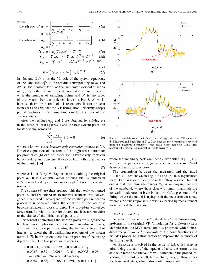
Fig. 4. (a) Measured and fitted data of Y12 with the VF approach.(b) Measured and fitted data of Y23. Dash lines are the Y -parameter convertedfrom the measured S-parameter with phase offset removed. Solid linesrepresent the rational approximation result given by VF.
where the imaginary parts are linearly distributed in [−1, 1.1]and the real parts are all negative and the values are 1% ofthose of the imaginary parts.
The comparison between the measured and the fittedY12 and Y23 are shown in Fig. 4(a) and (b) in a logarithmicscale. Two issues are identified in the fitting results. The firstone is that the trans-admittances Y12 is under-fitted outsideof the passband, where those data with small magnitude arenot well fitted. Another issue is the over-fitting problem in Y23fitting, where the model is trying to fit the measurement noise,whereas the true response is obviously buried by measurementnoise beyond the passband.
B. MVF Formulation
In order to deal with the “under-fitting” and “over-fitting”problems in the original VF formulation for diplexer systemidentification, the MVF formulation is proposed, which intro-duces the pole-located monomials as the basis functions andincludes proper weighting factors to improve the accuracy ofthe fitting result.
As the system is solved in the sense of LS, which aims atminimizing the sum of the squares of absolute errors, thosedata with large absolute values will dominate in the procedure,leading to absolutely small, but relatively large, fitting errorsfor those small data, which also contain important information

ZHAO AND WU: MVF METHOD FOR CIRCUIT MODEL EXTRACTION OF COUPLED-RESONATOR DIPLEXERS 1791
of the current state of the coupled resonators. In order to stressthe significance of those small-valued data, the weightingfactors, chosen as
Wpq = 1√|Ypq | (8)
are multiplied to the data of Y12 and Y13, which magnify theLS error of small data and minify the error of large data,thus the relative accuracy can be balanced. However, at thesame time, when the LS error of small data is stressed, themeasurement noise is also magnified, which deteriorates the“over-fitting” problem.
It is well known that, for a coupled-resonator filter, both theorder of the numerator of the transfer function S12 and that ofthe trans-admittance Y12 are equal to the number of TZs, whichcan be told from the routing diagram of the resonators. It is thesame with a coupled-resonator diplexer network. For example,in the testing diplexer, there is a tri-section in each channelfilter that introduces one TZ, and the five resonators from theother channel filter contribute five additional complex TZs onthe left half s-plane. Thus, both orders of the numerators ofY12 and Y13 are 6. The order of the numerator of Y23 is 2 asa result of the two cascaded tri-sections. Taking the parasiticcouplings into consideration, a more practical estimation isthat the orders of the numerators of Y12, Y13, and Y23 are7, 7, and 4, respectively.
The original VF formulation (4) uniformly adopts thepartial fractions as the basis functions for all six of theY -parameters in the Y -matrix. The model of linear combi-nation of partial fractions gives the numerator an excessivedegree of freedom than that actually needed, which makes themodel over attempting to fit the measurement noise in thefitting of the trans-admittances. Thus, the VF approach leadsto the “over-fitting” problem. In other words, the order of thenumerator cannot be fixed to be a number less than N − 1 inthe following equation:
Ypq(si ) � p(si )
σ (si )=
(N∑
k=1
ci jk
si−ak
)+ di j
(N∑
k=1
c̃i jk
si−ak
)+ 1
, i = 1, 2, . . . , m
(9)
where m denotes the total number of sampled data.To rectify this problem, for the self-admittance functions
Y11, Y22, and Y33, whose numerators and denominators areof the same order (if the diagonal elements of jMp in (2)are allowed to be non-zero), partial fractions are adopted asthe basis functions. For the trans-admittance functions Y12,Y13, and Y23, a new set of basis functions called pole-locatedmonomials defined by
1N∏
k=1(s − ak)
,s
N∏k=1
(s − ak)
, . . .sNz
N∏k=1
(s − ak)
(10)
are adopted, where Nz is the stipulated order of the numerator.Combining the weighting factors in (8) and replacing thepartial fraction basis functions for trans-admittance by the
new pole-located monomial basis functions in (10), (4) canbe reformulated as
⎡⎢⎢⎢⎢⎢⎢⎣
A1 0 0 0 0 0 −Y11A20 W12A3 0 0 0 0 −W12Y12A20 0 W13A3 0 0 0 −W13Y13A20 0 0 A1 0 0 −Y22A20 0 0 0 A4 0 −Y23A20 0 0 0 0 A1 −Y33A2
⎤⎥⎥⎥⎥⎥⎥⎦
⎡⎢⎢⎢⎢⎢⎢⎢⎢⎣
c11c12c13c22c23c33c̃
⎤⎥⎥⎥⎥⎥⎥⎥⎥⎦=
⎡⎢⎢⎢⎢⎢⎢⎣
y11W12y12W13y13
y22y23y33
⎤⎥⎥⎥⎥⎥⎥⎦
(11)
where
W12 = diag{ 1√|Y12(si )| } ∈ Rm×m (12a)
W13 = diag{ 1√|Y13(si )| } ∈ Rm×m (12b)
the i th row of A3
=
⎡⎢⎢⎢⎣ 1
N∏k=1
(si − ak)
si
N∏k=1
(si − ak)
· · · s7i
N∏k=1
(si − ak)
⎤⎥⎥⎥⎦
A3 ∈ Cm×8 (12c)
the i th row of A4
=
⎡⎢⎢⎢⎣ 1
N∏k=1
(si − ak)
si
N∏k=1
(si − ak)
· · · s4i
N∏k=1
(si − ak)
⎤⎥⎥⎥⎦
A4 ∈ Cm×5. (12d)
Different from the variables in (4), with the pole-locatedmonomials as the basis functions for Y12, Y13, and Y23, thevariables c12 ∈ C8×1, c13 ∈ C8×1, and c23 ∈ C5×1 in (11) arenot the residues. In stead they are the coefficients of the basisfunctions defined by (10).
With the new basis functions, the iterative pole relocationprocedure of the original VF formulation are retained toguarantee the accuracy of the poles and residues obtained.The initial poles are chosen as the same with those in previousVF formulation and convergence is also achieved within a fewiterations.
For comparison purposes, the fitting of Y12 and Y23using the MVF approach are shown in Fig. 5(a) and (b),respectively. The improvement is obvious as compared withFig. 4(a) and (b) in that those small data in Y12 and Y13 arebetter fitted in the presence of measurement noise and Y23 isaccurately recovered under the noise floor.
The MVF adopts mixed basis functions to fit the elementsin the Y -matrix together. In the new formulation, the ordersof the numerators are stipulated to be consistent with thecoupling topology of the diplexer. Thus it can reduce themodel’s sensitivity to the measurement noise in a practicalmeasurement environment.

1792 IEEE TRANSACTIONS ON MICROWAVE THEORY AND TECHNIQUES, VOL. 64, NO. 6, JUNE 2016
Fig. 5. (a) Measured and fitted Y12 with the MVF approach. (b) Measuredand fitted Y23 with the MVF approach.
IV. SYNTHESIS OF THE TRANSVERSAL COUPLING MATRIX
The poles ak and the residues rpqk can be obtained once
the MVF procedure has converged and the rational functionsare transformed to the form of
Ypq = K pq +N∑
k=1
rpqk
s − ak. (13)
Comparing (13) with (2), it can be seen that the relationshipbetween the poles and residues of the Y -parameter rationalfunctions and the elements in the transversal coupling matrix is
MP1,k2 = r11
k
MP1,k MP2,k = r12k
MP1,k MP3,k = r13k
MP2,k2 = r22
k
MP2,k MP3,k = r23k
MP3,k2 = r33
k
Mk,k = 1j∗ak, k = 1, 2, . . . N. (14)
From (14), it can be seen that in order to synthesize atransversal coupling matrix, the residues should satisfy thecompactness condition
r12kr12
k = r11kr22
k
r13kr13
k = r11kr33
k
r23kr23
k = r22kr33
k, k = 1, 2, . . . , N. (15)
Since no constraint is applied to the residues in the MVFprocedure, (15) is not guaranteed to be satisfied. However,when applying the MVF formulation to measured data of thediplexer, it is observed that (15) is automatically satisfied withonly very small errors. Therefore, a transversal coupling matrixcan be synthesized with the following strategy:
for k = 1 to N
Mk,k = 1j∗ak
if |rk11| > |rk
22| and |rk11| > |rk
33|MP1,k =
√r11
k, MP2,k = r12k/
√r11
k , MP3,k = r13k/
√r11
k
elseif |r22k | > |r11
k | and |r22k | > |r33
k |MP2,k =
√r22
k, MP1,k = r12k/
√r22
k , MP3,k = r23k/
√r22
k
elseif |r33k | > |r11
k | and |r33k | > |r22
k |MP3,k =
√r33
k, MP1,k = r13k/
√r33
k , MP2,k = r23k/
√r33
k
end
Mk,P1 = MP1,k , Mk,P2 = MP2,k , Mk,P3 = MP3,k ,
end
MP1,P1 = K11/1j, MP2,P2 = K22/1j, MP3,P3 = K33/1j
where 1j stands for the imaginary unit j in a complex number,and Mx,y denotes the element in the row of node x and columnof node y in the coupling matrix M.
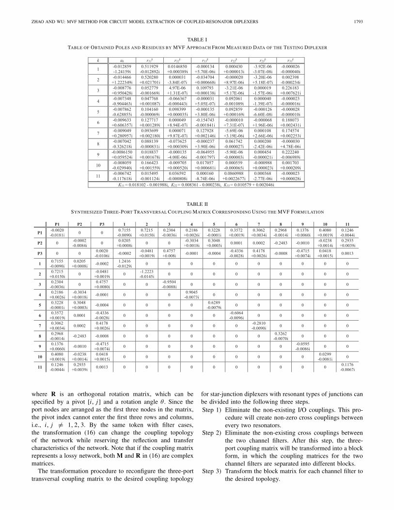
For example, the poles and residues obtained for one of thetuning states of the testing diplexer are listed in Table I. Thesynthesized transversal coupling matrix using the proposedstrategy above is given in Table II. The responses of thesynthesized coupling matrix are superimposed to the rawmeasured data for comparison in Fig. 6. It can be seen that theresponses of the extracted transversal coupling matrix agreewell with the measured data up to −80 dB.
V. TRANSFORMATION OF THREE-PORT
COUPLING MATRIX
The derivation of the transversal coupling matrix alonecannot help with the tuning of the diplexer because one-to-onecorrespondence between physical tuning elements and thecoupling matrix elements is established only after the matrix istransformed to the right configuration. Many coupling matrixrotation recipes are available for coupled-resonator filters [18],and a general multi-port coupling matrix reconfiguration pro-cedure is proposed in [19], where many coupling topologiesare discussed. However, for the star-junction diplexers withresonant types of junctions discussed in this paper, a straight-forward procedure exists and can be implemented in thediplexer circuit model extraction program.
A. General Procedure for Diplexers
The three-port coupling matrix of the diplexer can bereconfigured by matrix similarity transformation by followingthe same rules for filter transformations, i.e.,
[M′] = [R][M][R]T (16)
ZHAO AND WU: MVF METHOD FOR CIRCUIT MODEL EXTRACTION OF COUPLED-RESONATOR DIPLEXERS 1793
TABLE I
TABLE OF OBTAINED POLES AND RESIDUES BY MVF APPROACH FROM MEASURED DATA OF THE TESTING DIPLEXER
TABLE II
SYNTHESIZED THREE-PORT TRANSVERSAL COUPLING MATRIX CORRESPONDING USING THE MVF FORMULATION
where R is an orthogonal rotation matrix, which can bespecified by a pivot [i, j ] and a rotation angle θ . Since theport nodes are arranged as the first three nodes in the matrix,the pivot index cannot enter the first three rows and columns,i.e., i, j �= 1, 2, 3. By the same token with filter cases,the transformation (16) can change the coupling topologyof the network while reserving the reflection and transfercharacteristics of the network. Note that if the coupling matrixrepresents a lossy network, both M and R in (16) are complexmatrices.
The transformation procedure to reconfigure the three-porttransversal coupling matrix to the desired coupling topology
for star-junction diplexers with resonant types of junctions canbe divided into the following three steps.Step 1) Eliminate the non-existing I/O couplings. This pro-
cedure will create non-zero cross couplings betweenevery two resonators.
Step 2) Eliminate the non-existing cross couplings betweenthe two channel filters. After this step, the three-port coupling matrix will be transformed into a blockform, in which the coupling matrices for the twochannel filters are separated into different blocks.
Step 3) Transform the block matrix for each channel filter tothe desired topology.

1794 IEEE TRANSACTIONS ON MICROWAVE THEORY AND TECHNIQUES, VOL. 64, NO. 6, JUNE 2016
Fig. 6. Comparison of the measured and fitted S11, S12, and S13 data with themodel extracted by MVF formulation. Dashed color lines are measured data.Black solid lines are the response given by the extracted three-port transversalcoupling matrix with the MVF technique.
Fig. 7. (a) Transversal coupling matrix. (b) Matrix after I/O coupling areannihilated. (c) Matrix after the couplings between the two channel filters areannihilated to the best effort. (d) Final target topology.
The last step allows the utilization of those well-establishedfilter transformation strategies in [18] since the two channelfilters can be reconfigured individually. Thus the generalprocedure can be applied to those diplexers that are composedof high-degree channel filters and with many TZs connectedby a common resonator junction.
B. Specific Example
In this paper, a customized recipe is introduced to transformthe three-port transversal coupling matrix to the desired cou-pling topology for the testing diplexer shown in Fig. 3(b) byfollowing the three steps in the general procedure.
TABLE III
ROTATION SEQUENCE TO RECONFIGURE THE COUPLING MATRIX
The matrix transformation procedure is depictedin Fig. 7(a)–(d), where the hollow circles represent expectednon-zero entries at each stage. The first three rows/columnsof the coupling matrix correspond to P1–P3 in Fig. 3(b)and the remaining 11 rows/columns correspond toresonators No. 1–11. Resonators No. 1–5 constitute thelower band channel filter and resonators No. 7–11 constitutethe upper band channel filter. Resonator No. 6 is the commonresonant node. The coupling matrices in Fig. 7 are partitionedaccording to the role that each row/column plays for aclear demonstration of the coupling matrix reconfigurationprocedure. Fig. 7(a) is the three-port transversal couplingmatrix. In the first step, non-existing I/O couplings areannihilated. The resultant matrix configuration is shownin Fig. 7(b). In the second stage, the cross-couplings betweenthe two channel filters are annihilated as many as possible.This leaves the TZ of each channel filter with a trisectionconnected to the common resonator. In the last stage, thetrisections are “pulled” to the right positions. The non-zeroentries in the coupling matrix in Fig. 7(d) have a one-to-onerelationship with the coupling topology of Fig. 3(b). Thedetails of the rotation sequence are provided in Table III,where the 1 ∼ 27 steps correspond to stage I, 28 ∼ 55 stepscorrespond to stage II and the last four steps are in stage III.Once the first two stages are finished, the cross couplingswill be separated into the two channel filters. Having hadthat, the reconfiguration of each channel filter can be doneindividually with well-established filter transformation recipesin [18].
ZHAO AND WU: MVF METHOD FOR CIRCUIT MODEL EXTRACTION OF COUPLED-RESONATOR DIPLEXERS 1795
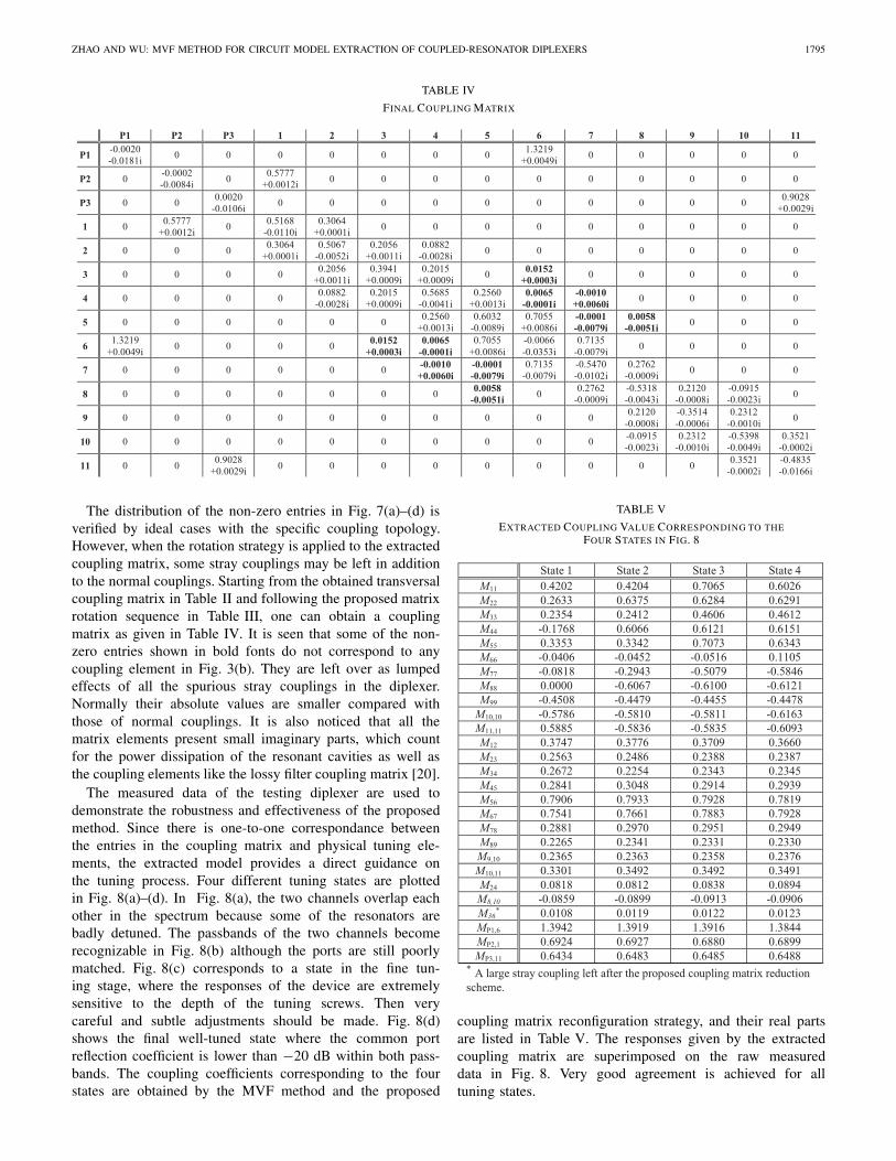
TABLE IV
FINAL COUPLING MATRIX
The distribution of the non-zero entries in Fig. 7(a)–(d) isverified by ideal cases with the specific coupling topology.However, when the rotation strategy is applied to the extractedcoupling matrix, some stray couplings may be left in additionto the normal couplings. Starting from the obtained transversalcoupling matrix in Table II and following the proposed matrixrotation sequence in Table III, one can obtain a couplingmatrix as given in Table IV. It is seen that some of the non-zero entries shown in bold fonts do not correspond to anycoupling element in Fig. 3(b). They are left over as lumpedeffects of all the spurious stray couplings in the diplexer.Normally their absolute values are smaller compared withthose of normal couplings. It is also noticed that all thematrix elements present small imaginary parts, which countfor the power dissipation of the resonant cavities as well asthe coupling elements like the lossy filter coupling matrix [20].
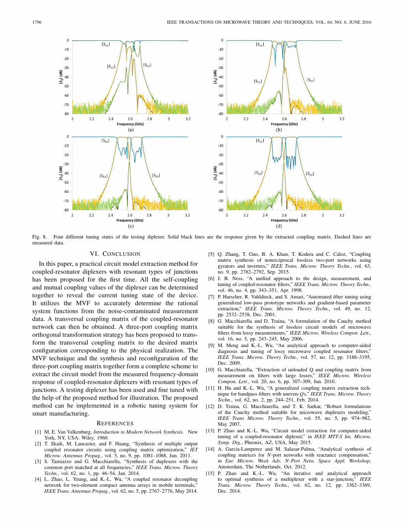
The measured data of the testing diplexer are used todemonstrate the robustness and effectiveness of the proposedmethod. Since there is one-to-one correspondance betweenthe entries in the coupling matrix and physical tuning ele-ments, the extracted model provides a direct guidance onthe tuning process. Four different tuning states are plottedin Fig. 8(a)–(d). In Fig. 8(a), the two channels overlap eachother in the spectrum because some of the resonators arebadly detuned. The passbands of the two channels becomerecognizable in Fig. 8(b) although the ports are still poorlymatched. Fig. 8(c) corresponds to a state in the fine tun-ing stage, where the responses of the device are extremelysensitive to the depth of the tuning screws. Then verycareful and subtle adjustments should be made. Fig. 8(d)shows the final well-tuned state where the common portreflection coefficient is lower than −20 dB within both pass-bands. The coupling coefficients corresponding to the fourstates are obtained by the MVF method and the proposed
TABLE V
EXTRACTED COUPLING VALUE CORRESPONDING TO THEFOUR STATES IN FIG. 8
coupling matrix reconfiguration strategy, and their real partsare listed in Table V. The responses given by the extractedcoupling matrix are superimposed on the raw measureddata in Fig. 8. Very good agreement is achieved for alltuning states.
1796 IEEE TRANSACTIONS ON MICROWAVE THEORY AND TECHNIQUES, VOL. 64, NO. 6, JUNE 2016
Fig. 8. Four different tuning states of the testing diplexer. Solid black lines are the response given by the extracted coupling matrix. Dashed lines aremeasured data.
VI. CONCLUSION
In this paper, a practical circuit model extraction method forcoupled-resonator diplexers with resonant types of junctionshas been proposed for the first time. All the self-couplingand mutual coupling values of the diplexer can be determinedtogether to reveal the current tuning state of the device.It utilizes the MVF to accurately determine the rationalsystem functions from the noise-contaminated measurementdata. A transversal coupling matrix of the coupled-resonatornetwork can then be obtained. A three-port coupling matrixorthogonal transformation strategy has been proposed to trans-form the transversal coupling matrix to the desired matrixconfiguration corresponding to the physical realization. TheMVF technique and the synthesis and reconfiguration of thethree-port coupling matrix together form a complete scheme toextract the circuit model from the measured frequency-domainresponse of coupled-resonator diplexers with resonant types ofjunctions. A testing diplexer has been used and fine tuned withthe help of the proposed method for illustration. The proposedmethod can be implemented in a robotic tuning system forsmart manufacturing.
REFERENCES
[1] M. E. Van Valkenburg, Introduction to Modern Network Synthesis. NewYork, NY, USA: Wiley, 1960.
[2] T. Skaik, M. Lancaster, and F. Huang, “Synthesis of multiple outputcoupled resonator circuits using coupling matrix optimization,” IETMicrow. Antennas Propag., vol. 5, no. 9, pp. 1081–1088, Jun. 2011.
[3] S. Tamiazzo and G. Macchiarella, “Synthesis of duplexers with thecommon port matched at all frequencies,” IEEE Trans. Microw. TheoryTechn., vol. 62, no. 1, pp. 46–54, Jan. 2014.
[4] L. Zhao, L. Yeung, and K.-L. Wu, “A coupled resonator decouplingnetwork for two-element compact antenna arrays in mobile terminals,”IEEE Trans. Antennas Propag., vol. 62, no. 5, pp. 2767–2776, May 2014.
[5] Q. Zhang, T. Guo, B. A. Khan, T. Kodera and C. Caloz, “Couplingmatrix synthesis of nonreciprocal lossless two-port networks usinggyrators and inverters,” IEEE Trans. Microw. Theory Techn., vol. 63,no. 9, pp. 2782–2792, Sep. 2015.
[6] J. B. Ness, “A unified approach to the design, measurement, andtuning of coupled-resonator filters,” IEEE Trans. Microw. Theory Techn.,vol. 46, no. 4, pp. 343–351, Apr. 1998.
[7] P. Harscher, R. Vahldieck, and S. Amari, “Automated filter tuning usinggeneralized low-pass prototype networks and gradient-based parameterextraction,” IEEE Trans. Microw. Theory Techn., vol. 49, no. 12,pp. 2532–2538, Dec. 2001.
[8] G. Macchiarella and D. Traina, “A formulation of the Cauchy methodsuitable for the synthesis of lossless circuit models of microwavefilters from lossy measurements,” IEEE Microw. Wireless Compon. Lett.,vol. 16, no. 5, pp. 243–245, May 2006.
[9] M. Meng and K.-L. Wu, “An analytical approach to computer-aideddiagnosis and tuning of lossy microwave coupled resonator filters,”IEEE Trans. Microw. Theory Techn., vol. 57, no. 12, pp. 3188–3195,Dec. 2009.
[10] G. Macchiarella, “Extraction of unloaded Q and coupling matrix frommeasurement on filters with large losses,” IEEE Microw. WirelessCompon. Lett., vol. 20, no. 6, pp. 307–309, Jun. 2010.
[11] H. Hu and K.-L. Wu, “A generalized coupling matrix extraction tech-nique for bandpass filters with uneven-Qs,” IEEE Trans. Microw. TheoryTechn., vol. 62, no. 2, pp. 244–251, Feb. 2014.
[12] D. Traina, G. Macchiarella, and T. K. Sarkar, “Robust formulationsof the Cauchy method suitable for microwave duplexers modeling,”IEEE Trans Microw. Theory Techn., vol. 55, no. 5, pp. 974–982,May 2007.
[13] P. Zhao and K.-L. Wu, “Circuit model extraction for computer-aidedtuning of a coupled-resonator diplexer,” in IEEE MTT-S Int. Microw.Symp. Dig., Pheonix, AZ, USA, May 2015.
[14] A. Garcia-Lamperez and M. Salazar-Palma, “Analytical synthesis ofcoupling matrices for N -port networks with reactance compensation,”in Eur. Microw. Week Adv. N-Port Netw. Space Appl. Workshop,Amsterdam, The Netherlands, Oct. 2012.
[15] P. Zhao and K.-L. Wu, “An iterative and analytical approachto optimal synthesis of a multiplexer with a star-junction,” IEEETrans. Microw. Theory Techn., vol. 62, no. 12, pp. 3362–3369,Dec. 2014.
ZHAO AND WU: MVF METHOD FOR CIRCUIT MODEL EXTRACTION OF COUPLED-RESONATOR DIPLEXERS 1797
[16] B. Gustavsen and A. Semlyen, “Simulation of transmission line tran-sients using vector fitting and modal decomposition,” IEEE Trans. PowerDel., vol. 13, no. 2, pp. 605–614, Apr. 1998.
[17] B. Gustavsen and A. Semlyen, “Rational approximation of frequencydomain responses by vector fitting,” IEEE Trans. Power Delivery,vol. 14, no. 3, pp. 1052–1061, Jul. 1999.
[18] R. J. Cameron, C. M. Kudsia, and R. R. Mansour, Microwave Filtersfor Communication Systems: Fundamentals, Design and Applications.Hoboken, NJ, USA: Wiley, 2007.
[19] G. Macchiarella and S. Tamiazzo, “Generation of canonical forms formultiport filtering networks,” in IEEE MTT-S Int. Microw. Symp. Dig.,Tampa, FL, USA, Jun. 2014.
[20] V. Miraftab and M. Yu, “Generalized lossy microwave filter couplingmatrix synthesis and design using mixed technologies,” IEEE TransMicrow. Theory Techn., vol. 56, no. 12, pp. 3016–3027, Dec. 2008.
Ping Zhao (S’14) received the B.Sc. degree fromNanjing University, Nanjing, China, in 2012, andis currently working toward the Ph.D. degree atThe Chinese University of Hong Kong, Shatin,Hong Kong.
His research is focused on synthesis andcomputer-aided tuning (CAT) algorithms for multi-port microwave coupled-resonator networks, includ-ing diplexers, multiplexers, and coupled- resonatordecoupling networks with applications in cellularbase stations and satellites.
Mr. Zhao was the recipient of the Honorable Mention in the 2014 IEEEMicrowave Theory and Techniques Society (IEEE MTT-S) InternationalMicrowave Symposium (IMS) Student Paper Competition. He was also therecipient of the Best Student Paper Award of the 2014 IEEE HK AP/MTTPostgraduate Conference.
Ke-Li Wu (M’90–SM’96–F’11) received the B.S.and M.Eng. degrees from the Nanjing University ofScience and Technology, Nanjing, China, in 1982and 1985, respectively, and the Ph.D. degree fromLaval University, Quebec, QC, Canada, in 1989.
From 1989 to 1993, he was with the Communi-cations Research Laboratory, McMaster University,as a Research Engineer and a Group Manager.In March 1993, he joined the Corporate R&D Divi-sion, COM DEV International (the largest Canadianspace equipment manufacturer), where he was a
Principal Member of Technical Staff. Since October 1999, he has beenwith The Chinese University of Hong Kong, Shatin, Hong Kong, wherehe is currently a Professor and the Director of the Radiaofrequency Radi-ation Research Laboratory (R3L). He has authored or coauthored numerouspublications in the areas of electromagnetic (EM) modeling and microwavepassive components, microwave filters, and antenna engineering. His currentresearch interests include partial element equivalent circuit (PEEC) andderived physically expressive circuit (DPEC) EM modeling of high-speedcircuits, RF and microwave passive circuits and systems, synthesis theoryand practices of microwave filters, antennas for wireless terminals, low-temperature co-fired ceramic (LTCC)-based multichip modules (MCMs), andRF identification (RFID) technologies.
Prof. Wu is a Member of the IEEE MTT-8 Subcommittee (Filters andPassive Components). He also serves as a Technical Program Commit-tee (TPC) Member for many prestigious international conferences includingthe IEEE Microwave Theory and Techniques Society (IEEE MTT-S) Inter-national Microwave Symposium (IMS). He was an Associate Editor for theIEEE TRANSACTIONS ON MICROWAVE THEORY AND TECHNIQUES from2006 to 2009. He was the recipient of the 1998 COM DEV AchievementAward for the development of exact EM design software of microwave filtersand multiplexers and the Asia–Pacific Microwave Conference Prize in 2008and 2012, respectively.