IEEE Modeling of Permanent Magnet Motor Drivesusers.encs.concordia.ca/~pillay/55.pdf · PRAGASAN...
5
IEEE TRANSACTIONS ON INDUSTRIAL ELECTRONICS, VOL. 35, NO.4, NOVEMBER 1988 " Modeling of Permanent Magnet Motor Drives PRAGASAN PILLAY, MEMBER, IEEE, ANDR. KRISHNAN, MEMBER, IEEE Abstract-Recent research has Indicated (hat (he permanent magnet motor drives, which include the permanent magnet synchronous motor (PMSM) and the brushless dc motor (BDCM) could become serious competitors to the induction motor for servo applications. The PMSM has a sinusoidal back emf and requires sinusoidal stator currents to produce constant torque while the BDCM has a trapezoidal back emf and requires rectangular stator currents to produce constant torque. The PMSM is very similar to the wound rotor synchronous machine except that the PMSM that is used for servo applications tends not to have any damper windings and excitation is provided by a permanent magnet instead of a fi~ld winding. Hence the d, q model of the PMSM can be derived from the well-known model of the synchronous machine with the equations of the damper windings and field current dynamics removed. Because of tbe nonsinusoidal variation of the mutual inductances between the stator and rotor in the BDCM, it is also shown In this paper that no particular advantage exists in transforming the abc equations of the BCDM to the d, q frame. Hence the solution of the original abc equations is proposed for the BDCM. B ea, eb, ec Ep ia, ib, ic id, iq' J La, Lb, Lc Lab Ld, Lq p P R Te T, Va, Vb, Vc Vd, Vq Vdc Aaf Ad, Aq Wr Ws Or * NOMENCLATURE damping constant, Nlradls (in Newtons per radian per second) a, b, and c phase back emfs (in volts) peak value of back emf (in volts) a, b, and c phase currents, (in amperes) d, q axis stator currents (in amperes) moment of inertia, kg - m2 self inductance of a, b, and c phases (in henrys) mutual inductance between phases a and b (in henrys) d, q axis inductances (in henrys) derivative operator - number of pole pairs stator resistance (in ohms) electric torque (in newton meters) load torque, (in newton meters) a, b, and c phase voltages (in volts) d,. q axis voltages (in volts) dc bus voltage (in volts) mutual flux due to magnet (in webers) d, q axis flux linkages (in webers) rotor speed (in radians per second) synchronous speed, (in radians per second) angle between stator phase A and the rotor (in radians) superscript indicating reference value Manuscript received September 4, 1987; revised March 21, 1988. The authors are with the Electrical Engineering Department, Virginia Polytechnic Institute and State University, BIacksburg, VA 24061. IEEE Log Number 8823354. I. INTRODUCTION DECENT research [1]-[3] has indicated that the permanent .Rmagnet motor drives, which include the permanent magnet synchronous motor (PMSM) and the brushless dc motor (BDCM) could become serious competitors to the induction motor for servo applications. The PMSM has a sinusoidal back emf and requires sinusoidal stator currents to produce constant torque while the BDCM has a trapezoidal back emf and requires rectangular stator currents to produce constant torque. Some confusion exists, both in the industry and in the university research environment, as to the correct models that should be used in each case. The PMSM is very similar to the standard wound rotor synchronous machine except that the PMSM has no damper windings and excitation is provided by a permanent magnet instead of a field winding. Hence the d, q model of the PMSM can be derived from the well-known [4] model of the synchronous machine with the equations of the damper windings and field current dynamics removed. \ As is well known, the transformation of the synchronous machine equations from the abc phase variables to the d, q variables forces all si~usoidally varying inductances in the abc frame to become constant-in the d, q frame. In the BDCM motor, since the back emf is nonsinusoidal, the inductances do not vary sinusoidally in the abc frame and it does not seem advantageous to transform the equations to the d, q frame since the inductances will not be constant after transformation. - Hence it is proposed to use the abc phase variables model for the BDCM. In addition, this approach in the modeling of the BDCM allows a detailed examination of the machine's torque behavior that would not be possible if any simplifying assumptions were made. The d, q model of the PMSM has been used to examine the transient behavior of a high-performance vector controlled PMSM servo drive [5]. In addition, the abc phase variable model has been used to examine the behavior of a BDCM speed servo drive [6]. Application characteristics of both machines have been presented in [7]. The purpose of this paper is to present these two models together and to show that the d, q model is sufficient to study the PMSM in detail while the abc model should be used in order to study the BDCM. It is therefore tutorial in nature and summarizes previously published work on the PMSM and BDCM. The paper is arranged as follows: Section II presents the mathematical model of the PMSM. Section III presents the mathematical model of the BDCM. Section IV uses these models to present some key results to illustrate the use of these models to study both transient and steady state behavior of these drive systems. Section IV has the conclusions. 0278-0046/88/1100-0537$01.00 @ 1988 IEEE 537 i." 'ii 'r,:, ,~' ::(:' '..' " ~( I... J ,.. :;:\~ k r, f;' .,. ;".: -- :,1 i,- ,I,' r~' j: '!' ~' i ~. ",.. ,< ,., ,,' , , ; i': 'I; ~- p ~, . /. -'.
Transcript of IEEE Modeling of Permanent Magnet Motor Drivesusers.encs.concordia.ca/~pillay/55.pdf · PRAGASAN...

IEEE TRANSACTIONS ON INDUSTRIAL ELECTRONICS, VOL. 35, NO.4, NOVEMBER 1988"
Modeling of Permanent Magnet Motor DrivesPRAGASAN PILLAY, MEMBER,IEEE, ANDR. KRISHNAN, MEMBER,IEEE
Abstract-Recent research has Indicated (hat (he permanent magnetmotor drives, which include the permanent magnet synchronous motor(PMSM) and the brushless dc motor (BDCM) could become seriouscompetitors to the induction motor for servo applications. The PMSMhas a sinusoidal back emf and requires sinusoidal stator currents toproduce constant torque while the BDCM has a trapezoidal back emf andrequires rectangular stator currents to produce constant torque. ThePMSM is very similar to the wound rotor synchronous machine exceptthat the PMSM that is used for servo applications tends not to have anydamper windings and excitation is provided by a permanent magnetinstead of a fi~ld winding. Hence the d, q model of the PMSM can bederived from the well-known model of the synchronous machine with theequations of the damper windings and field current dynamics removed.Because of tbe nonsinusoidal variation of the mutual inductances between
the stator and rotor in the BDCM, it is also shown In this paper that noparticular advantage exists in transforming the abc equations of theBCDM to the d, q frame. Hence the solution of the original abc equationsis proposed for the BDCM.
B
ea, eb, ecEpia, ib, icid, iq'J
La, Lb, Lc
Lab
Ld, LqpPR
TeT,
Va, Vb, Vc
Vd, Vq
Vdc
Aaf
Ad, AqWr
Ws
Or
*
NOMENCLATURE
damping constant, Nlradls (in Newtons perradian per second)a, b, and c phase back emfs (in volts)peak value of back emf (in volts)a, b, and c phase currents, (in amperes)d, q axis stator currents (in amperes)moment of inertia, kg - m2
self inductance of a, b, and c phases (inhenrys)mutual inductance between phases a and b (inhenrys)d, q axis inductances (in henrys)derivative operator -
number of pole pairsstator resistance (in ohms)electric torque (in newton meters)load torque, (in newton meters)a, b, and c phase voltages (in volts)d,. q axis voltages (in volts)dc bus voltage (in volts)mutual flux due to magnet (in webers)d, q axis flux linkages (in webers)rotor speed (in radians per second)synchronous speed, (in radians per second)angle between stator phase A and the rotor (inradians)superscript indicating reference value
Manuscript received September 4, 1987; revised March 21, 1988.The authors are with the Electrical Engineering Department, Virginia
Polytechnic Institute and State University, BIacksburg, VA 24061.IEEE Log Number 8823354.
I. INTRODUCTION
DECENT research [1]-[3] has indicated that the permanent.Rmagnet motor drives, which include the permanentmagnet synchronous motor (PMSM) and the brushless dcmotor (BDCM) could become serious competitors to theinduction motor for servo applications. The PMSM has asinusoidal back emf and requires sinusoidal stator currents toproduce constant torque while the BDCM has a trapezoidalback emf and requires rectangular stator currents to produceconstant torque. Some confusion exists, both in the industryand in the university research environment, as to the correctmodels that should be used in each case. The PMSM is verysimilar to the standard wound rotor synchronous machineexcept that the PMSM has no damper windings and excitationis provided by a permanent magnet instead of a field winding.Hence the d, q model of the PMSM can be derived from thewell-known [4] model of the synchronous machine with theequations of the damper windings and field current dynamicsremoved.
\
As is well known, the transformation of the synchronousmachine equations from the abc phase variables to the d, qvariables forces all si~usoidally varying inductances in the abcframe to become constant-in the d, q frame. In the BDCMmotor, since the back emf is nonsinusoidal, the inductances donot vary sinusoidally in the abc frame and it does not seemadvantageous to transform the equations to the d, q framesince the inductances will not be constant after transformation. -
Hence it is proposed to use the abc phase variables model forthe BDCM. In addition, this approach in the modeling of theBDCM allows a detailed examination of the machine's torquebehavior that would not be possible if any simplifyingassumptions were made.
The d, q model of the PMSM has been used to examine thetransient behavior of a high-performance vector controlledPMSM servo drive [5]. In addition, the abc phase variablemodel has been used to examine the behavior of a BDCMspeed servo drive [6]. Application characteristics of bothmachines have been presented in [7]. The purpose of thispaper is to present these two models together and to show thatthe d, q model is sufficient to study the PMSM in detail whilethe abc model should be used in order to study the BDCM. Itis therefore tutorial in nature and summarizes previouslypublished work on the PMSM and BDCM.
The paper is arranged as follows: Section II presents themathematical model of the PMSM. Section III presents themathematical model of the BDCM. Section IV uses these
models to present some key results to illustrate the use of thesemodels to study both transient and steady state behavior ofthese drive systems. Section IV has the conclusions.
0278-0046/88/1100-0537$01.00 @ 1988 IEEE
537i."
'ii'r,:,,~'
::(:''..'"~(I...J ,..
:;:\~kr,
f;'.,.;".:--:,1i,-
,I,'
r~'j:'!'~ '
i~ .",..
,<
,.,
,,',, ;
i':'I;
~-p~,.
/.
-'.
538
II. MATHEMATICAL MODEL OF THE PMSM
IEEE TRANSACTIONS ON INDUSTRIAL ELECTRONICS. VOL. 35. NO.4. NOVEMBER t988
The stator of the PMSM and the wound rotor synchronousmotor (SM) are similar.' In addition there is no differencebetween the back emf produced by a permanent magnet andthat produced by an excited coil. Hence the mathematicalmodel of a PMSM is similar to that of the wound rotor SM.
The following assumptions are made in the derivation:
1) Saturation is neglected although it can be taken intoaccount by parameter changes;
2) The back emf is sinusoidal;3) Eddy currents and hysteresis losses are negligible.
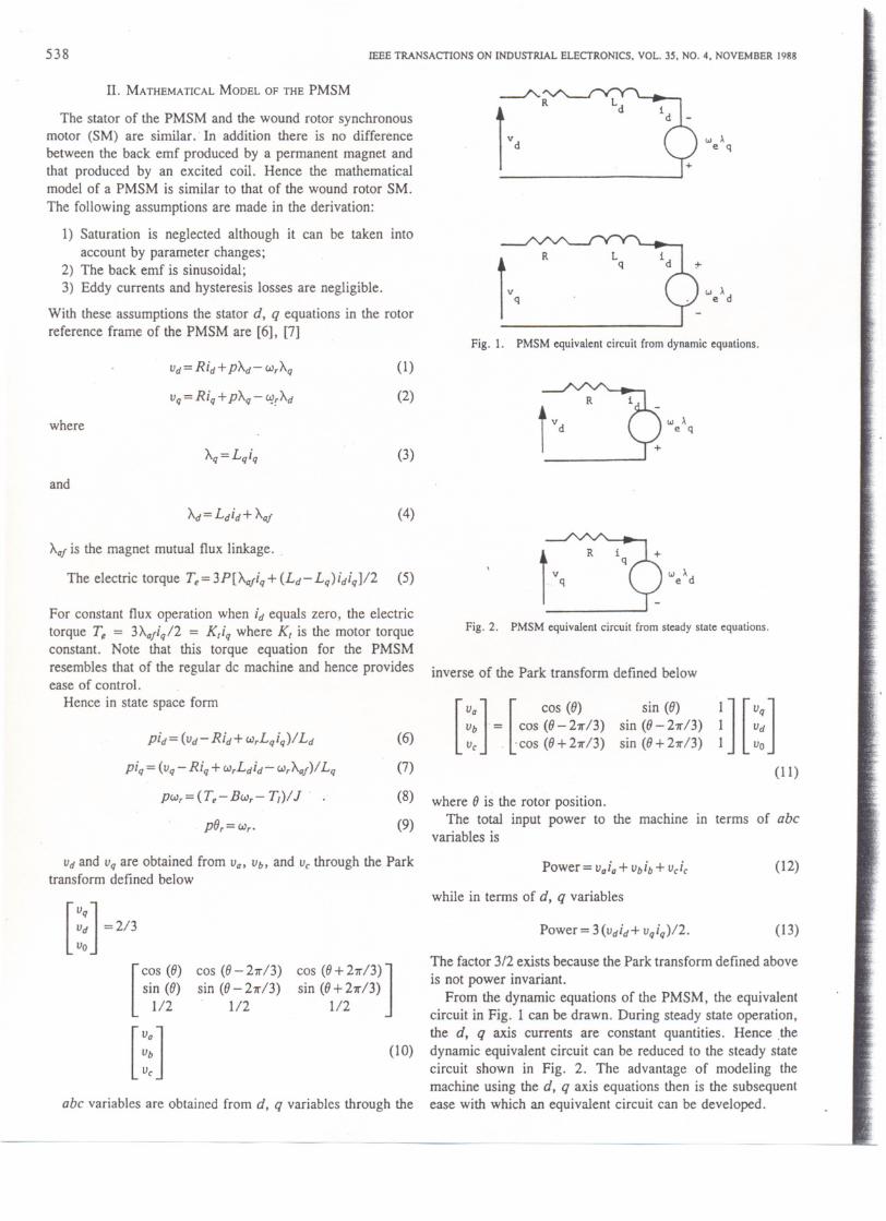
With these assumptions the stator d, q equations in the rotorreference frame of the PMSM are [6], [7]
Vd= Rid+ PAd- (J),Aq
Vq = Riq + PAq - ":rAd
where
Aq=Lqiq
and
Ad=Ldid+Aaj
Aajis the magnet mutual flux linkage. .
The electric torque T~=3P[~iq+(Ld-Lq)idiq]12
For constant flux operation when id equals zero, the electrictorque T, = 3Aafiq12 = K,iq where K, is the motor torqueconstant. Note that this torque equation for the PMSMresembles that of the regular dc machine and hence provideseaseof control. .
Hence in state space form
pid= (vd-Rid+ (J),Lqiq)ILd
piq = (Vq- Riq+ (J),Ldid~(J),Aaf)1Lq
p(J),=(T~-B(J)r- ~)IJ
pO,=(J),.
Vdand Vqare obtained from Va, Vb, and Vc-through the Parktransform defined below
m =213
[
COS (0) cos (0-21r/3) cos (0+ 27r/3)
]sin (0) sin (0-27r/3) sin (0 + 21r/3)
1/2 . 1/2 1/2
[::]abc variables are obtained from d, q variables through the
-
'" ~e qivd
we~d
ivq
R Lq
Fig. 1. PMSM equivalent circuit from dynamic equations.
(1)
(2) ~i~".'q(3)
(4)
(5) r:=9iq +v '" ~
q e d
Fig. 2. PMSM equivalent circuit from steady state equations.
inverse of the Park transform defined below
(6)
(7)
(8)
(9)
[
Va
] [
cos (0) sin (0)Vb = cos(0-21r/3) sin (0-27r/3)Vc . 'cos (0 + 21r/3) sin (0+ 27r/3) m::]
where 0 is the rotor position.The total input power to the machine in terms of abc
variables is
Power = vaia + vbib + vcic-
while in terms of d, q variables
Power = 3 (vdid+ vqiq)l2.
(10)
The factor 3/2 exists because the Park transform defined above
is not power invariant.From the dynamic equations of the PMSM, the equivalent
circuit in Fig. 1 can be drawn. During steady state operation,the d, q axis currents are constant quantities. Hence .thedynamic equivalent circuit can be reduced to the steady statecircuit shown in Fig. 2. The advantage of modeling themachine using the d, q axis equations then is the subsequentease with which an equivalent circuit can be developed.
(11)
(12)
(13)
PILLAY AND KRISHNAN: MODEUNG OF PERMANENT MAGNET MOTOR DRIVES 539
m. MATHEMATICALMODEL OF THE BDCM
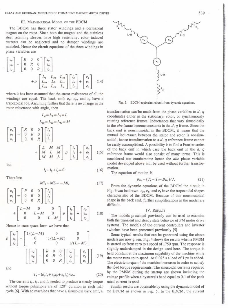
The BDCM has three stator windings and a permanentmagnet on the rotor. Since both the magnet and the stainlesssteel retaining sleeves have high resistivity, rotor inducedcurrents can be neglected and no damper windings aremodeled. Hence the circuit equations of the three windings inphase variables are
[
Va
] [
R 0 0
] [
ia
]Vb = 0 R 0 ~bVe 0 0 R Ie
[
La Lba Lea
] [
ia
] [
ea
]+p Lba Lb Leb ~b + eb
Lea Leb Le Ie ee
(14)
where it has been assumed that the stator resistances of all the
windings are equal. The back emfs ea, eb' and ee have atrapezoidal [6]. Assuming further that there is no change in therotor reluctance with angle, then
La=Lb=Le=L
Lab = Lea = Lbc = M
[
Va
] [
R 0 0
] [
ia
]Vb = 0 R 0 ~bVe 0 0 R Ie
[
L M M
] [
ia
] [
ea
]+ M L M P ~b + eb
M M L Ie ee
but
ia+ib+ie=O.
Therefore
Mib+Mie= -Mia
[
Va
] [
R 0 O
][
ia
]Vb = 0 R 0 ~bVe 0 0 R Ie
0
] [
ia
] [
ea
]~ p ~b + ebL M Ie ee[
L-M 0+ 0 L-M
0 0
Hence in state space form we have that
p
[
~a
]
-
[
lI(L-M)Ib - 0ie 0
[[
Va
] [
R ° 0
] [
ia
] [
ea
]]~: - .~ ~ ~ ~: - ::
0lI(L-M)
° lI(L~-M) ]
and
Tt = (eaia + ebib + eeie)/ (J),.
Fig. 3. BDCM equivalent circuit from dynamic equations.
transformation can'be made from the phase variables to d, qcoordinates either in the stationary, rotor, or synchronouslyrotating reference frames. Inductances that vary sinusoidallyin the abc frame become constants in the d, q frame. Since theback emf is nonsinusoidal in the BDCM, it means that themutual inductance between the stator and rotor is nonsinu-soidal, hence transformation to a d, q reference frame cannotbe easily accomplished. A possibility is to find a Fourier seriesof the back emf in which case the back emf in the d, q
(15) reference frame would also consist of many terms. This isconsidered too cumbersome hence the abc phase variablemodel developed above will be used without further transfor-
(16) mation.The equation of motion is
p(J),=(Te-Tf-B(J),)/J. (21)
From the dynamic equations of the BDCM the circuit inFig. 3 can be drawn. ea, eb, and eehave the trapezoidal shapescharacteristic of the BDCM. Because of this nonsinusoidal
shape in the back emf, further simplifications in the model aredifficult.
(17)
(18)IV. REsULTS
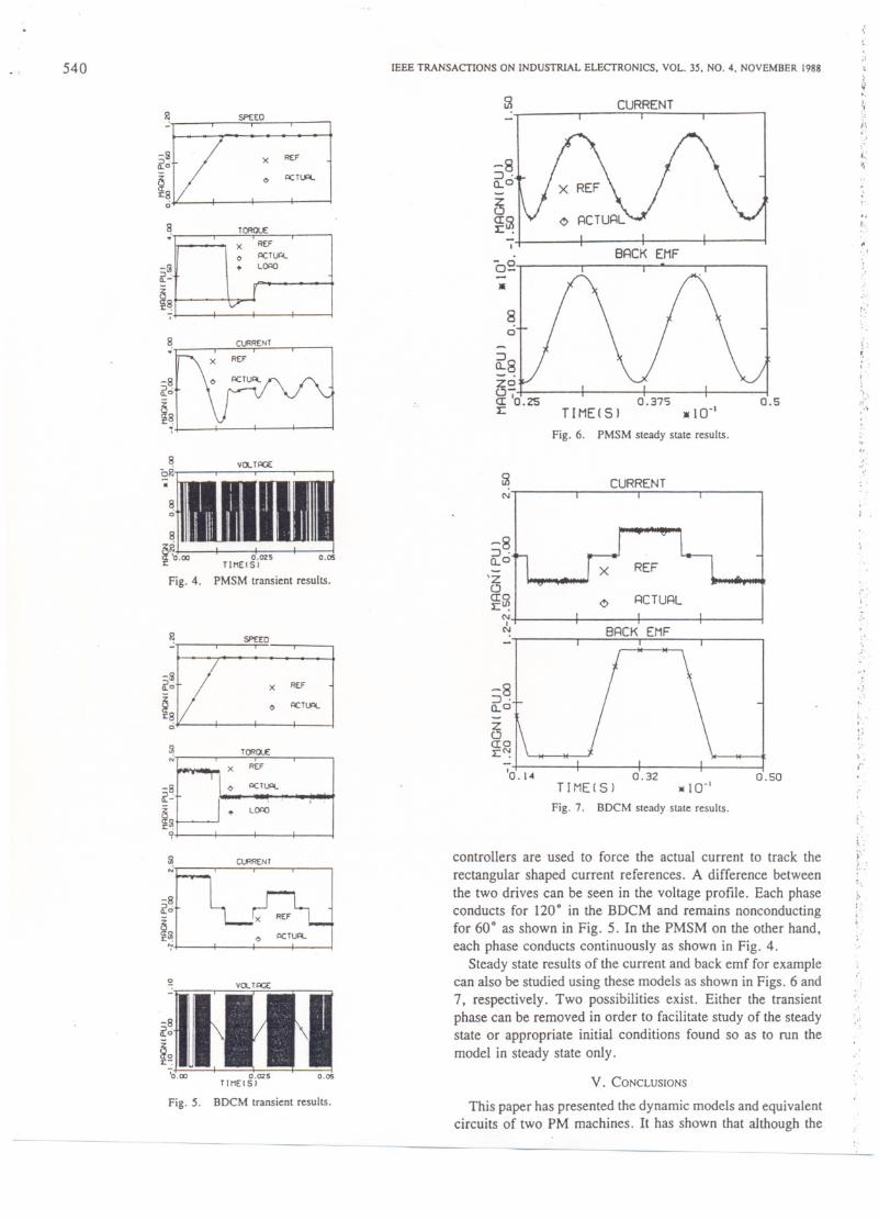
The models presented previously can be used to examineboth the transient and steady state behavior of PM' motor drivesystems. The models of the current controllers and inverterswitches have been presented previously [5J.
Some typical results that can be generated using the abovemodels are now given. Fig. 4 shows the results when a PMSMis started up from zero to a speed of 1750 rpm. The response isslightly underdamped in the design used here. The torque is
(19) held constant at the maximum capability of the machine whilethe motor runs up to speed. At 0.025 s a load of 1pu is added.The electric torque of the machine increases in order to satisfythe load torque requirements. The sinusoidal currents required
20 by the PMSM during the startup are shown including the( ) voltage profile when a hysteresis band equal to 0.1 of the peak
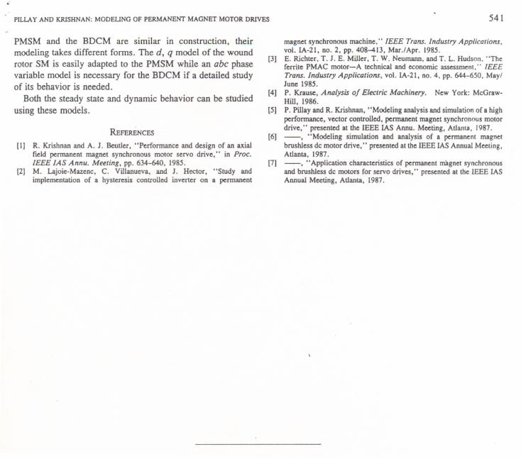
The currents ia, ib, and ieneeded to produce a steady torque. rated current is used.without torque pulsations are of 120' duration in each half Similar results are obtainable by using the dynamic model ofcycle [6]. With ac machines that have a sinusoidal back emf, a the BDCM as shown in Fig. 5. In the BDCM, the current
540
_~U5P(ED
~o X REF
~ <> I'>CTlA.:c8
0
~. TORaUE
-51~..;
§81:.,
~
~:::RENT
-8 0 I'>CTlA.~o
~8:c..~ VDLT~
:1lIJI§'0.00 0.025 0.05:c TIMEISI
Fig. 4. PMSM transient results.
_:oSPEED
~o X REF
§ <> I'>CTlA.1:8
ci
51 TORaUE
-8~..;g([51:c.
9
~
~C\.RRENT
-8~o x REF
i~ <> I'>CTlA.
0
-:nmVDLT~
~o
§o:c-:
'0.00 0.025 0.05TIME.SI
Fig. 5. BDCM transient results.
----
IEEE TRANSACTIONS ON INDUSTRIAL ELECTRONICS. VOL. 35. NO.4. NOVEMBER 1988
~".;
CURRENT ,.;(
-8:J.0...0
!.'
I..'..
~CI~1:.
I
"f...
BRCK EMF.
'"
o~-. :'
80
::;'
'.r.i'~~
~~CI '0'.251:
i
"'".;,..:.,
0.375.10"
0.5TIME! S)
Fig. 6. PMSM steady state results.,..
..
~"
".'"
CURRENTN
..'.. .
-8:J.a.°'z0CIOI:U'!
N.I
N
..RCTURL i'.~
.'BRCK EMF ..
-8:J.a.°
'..,..
".'."
,.,;~
CIOI: I'!
'0.14 0.32TIMEt S) -10"
Fig. 7. BDCM steady stale results.
0.50
controllers are used to force the actual current to track the
rectangular shaped current references. A difference betweenthe two drives can be seen in the voltage profile. Each phaseconducts for 120. in the BDCM and remains nonconductingfor 60. as shown in Fig. 5. In the PMSM on the other hand,each phase conducts continuously as shown in Fig. 4.
Steady state results of the current and back emf for examplecan also be studied using these models as shown in Figs. 6 and7, respectively. Two possibilities exist. Either the transientphase can be removed in order to facilitate study of the steadystate or appropriate initial conditions found so as to run themodel in steady state only.
i'.,}'-'i. .'
.\,
)..'
".'
V. CONCLUSIONS
This paper has presented the dynamic models and equivalentcircuits of two PM machines. It has shown that although the
REFX0 I'>CTlA.
+ L
YV
'U
x REF--,
"T
0 I'>CTlA.
L'
+
PILLAY AND KRISHNAN: MODEUNG OF PERMANENT MAGNET MOTOR DRIVES
PMSM and the BDCM are similar in construction, theirmodeling takes different forms. The d, q model of the woundrotor SM is easily adapted to the PMSM while an abc phasevariable model is necessary for the BDCM if a detailed studyof its behavior is needed.
Both the steady state and dynamic behavior can be studiedusing these models.
REFERENCES
[I] R. Krishnan and A. 1. Beutler, "Perfonnance and design of an axialfield pennanent magnet synchronous motor servo drive," in Proc.IEEE IAS Annu. Meeting, pp. 634-640, 1985.
[2] M. Lajoie-Mazenc, C. Villanueva, and 1. Hector, "Study andimplementation of a hysteresis controlled invener on a pennanent
541
magnet synchronous machine." IEEE Trans. Industry Applications.vol. 1A-21, no. 2, pp. 408-413, Mar.lApr. 1985.
[3] E. Richter. T.l. E. Miller, T. W. Neumann. and T. L. Hudson. "Theferrite PMAC motor-A technical and economic assessment," IEEETrans. Industry Applications, vol. 1A-21, no. 4, pp. 644-650, Mayllune 1985.
[4] P. Krause, Analysis of Electric Machinery. New York: McGraw-Hill, 1986.
[5] P. Pillay and R. Krishnan, "Modeling analysis and simulation oCa highperfonnance, vector controlled, pennanent magnet synchronous motordrive," presented at the IEEE IAS Annu. Meeting, Atlanta, 1987.
[6] -. "Modeling simulationand analysisof a permanentmagnetbrushless dc motor drive," presented at the IEEE IAS Annual Meeting,Atlanta, 1987.
[7] -, "Application characteristics of pennanent magnet synchronousand brushless dc motors for servo drives," presented at the IEEE IASAnnual Meeting, Atlanta, 1987.