ISSN: 2454-1362, A Closed · PDF filefield vector controlled Permanent magnet Synchronous...
7
Imperial Journal of Interdisciplinary Research (IJIR) Vol-2, Issue-6, 2016 ISSN: 2454-1362, http://www.onlinejournal.in Imperial Journal of Interdisciplinary Research (IJIR) Page 778 A Closed Loop Speed Control of PMSM Drive Using Fuzzy Logic Controller B.V.Lakshma Reddy 1 , U.Anjaiah 2 & T.Srinivasa Rao 3 1 PG Student Sch1or, AVANTHI Engineering College, Makavanpalem, Visakhapatnam. 2 Assistant Professor,AVANTHI Engineering College,Makavanpalem, Visakhapatnam. 3 Associate Professor,AVANTHI Engineering College,Makavanpalem, Visakhapatnam. Abstract-This paper presents a fuzzy logic controller (FLC) for speed control of permanent- magnet synchronous motor (PMSM) drive. With the approach of the field vector control methods, PMSM can be operated like separately excited dc motor in high performance applications. The difficulties of PI controller tuning and high response time is overcome by using fuzzy logic controller, which has small settling time and high percussion without any mathematical calculations. The PM synchronous motor has advantages in contrast with the AC induction motor. Because a PMSM achieves higher efficiency and regulation by generating the rotor magnetic flux with rotor magnets, a PMSM is used in totally enclosed traction motor, direct drive traction motor and high-end white goods such as fans and pumps; and in other appliances. Due to its high performance and reliability it's creates closed-loop speed control PM synchronous drive using a field vector control technique. It fulfill as an example of a PM Synchronous motor control design using a free scale hybrid controller with PE support. The proposed concept can be applied to fuzzy logic control system in order to improve the stability of the system by using MATLAB/SIMULATION software and the results are verified. Keywords- PMSM, vector control, modeling, closed loop, constant torque angle control, fuzzy logic controller. I.INTRODUCTION Industry automation is mainly expanded around motion control systems in which controlled electric motors play a critical part as heart of the system. Therefore, the high performance and efficiency motor control systems contribute, to a great extent, to the desirable performance of modern automated manufacturing sector by enhancing the production rate and the quality of products. In fact the implementation of modern automated systems, defined in terms of swiftness, accuracy, smoothness and efficiency. The advancement of control theories, power electronics and microelectronics in connection with new motor designs, patterns and materials has contributed largely to the field of electric motor control for high performance systems. The necessity for energy conservation is also one of the important motivations in the use of PM Synchronous machines. Field oriented control of PM Synchronous motor drive gives better performance in terms of faster dynamic response and more efficient operation. Field oriented control or vector control method gives the performance characteristics near to that of a dc machine which are considered desirable in certain applications [1, 2]. For high performance servo drives, Pulse width modulation current controllers are used to protect that currents flowing through the PMSM motor windings are as nearer to the as possible to sinusoidal references [3]. The implementation of field vector controlled Permanent magnet Synchronous motor (PMSM) drive through current controlled voltage source inverter has been described in the literature [4]. The inverter sending power to the PM Synchronous motor is normally fed from a diode bridge rectifier. The diode bridge rectifier has internal individual drawbacks such high power loss which leads to the lower power factor and it injects the harmonics into the AC supply system [5]. To overcome these difficulties, the diode bridge rectifier has been replaced by a PWM current controlled converter. The current controlled converter uses the high frequency self- commutated converter. This provides some specific benefit like higher power factor (Unity and leading), low and reduced level of harmonics, sinusoidal currents (i) and in reality the converter has the regeneration capacity. However not much attention has so far been paid to the examine the real time system, which may lead to a higher quality ,better understanding and deeper insight in to the advancement of the Field Oriented Control(FOC) of PMSM drive along with fuzzy PID control. This requirement is therefore felt to convey out the design of the PM Synchronous motor drive which includes the PID, Fuzzy system logic speed controller, converter, reference current generator, Pulse Width Modulation current controller, inverter and PMSM motor. Fuzzy logic is recently finding increasing implementations in
Transcript of ISSN: 2454-1362, A Closed · PDF filefield vector controlled Permanent magnet Synchronous...

Imperial Journal of Interdisciplinary Research (IJIR) Vol-2, Issue-6, 2016 ISSN: 2454-1362, http://www.onlinejournal.in
Imperial Journal of Interdisciplinary Research (IJIR) Page 778
A Closed Loop Speed Control of PMSM
Drive Using Fuzzy Logic Controller
B.V.Lakshma Reddy1, U.Anjaiah
2& T.Srinivasa Rao
3
1PG Student Sch1or, AVANTHI Engineering College, Makavanpalem, Visakhapatnam. 2Assistant Professor,AVANTHI Engineering College,Makavanpalem, Visakhapatnam.
3Associate Professor,AVANTHI Engineering College,Makavanpalem, Visakhapatnam.
Abstract-This paper presents a fuzzy logic
controller (FLC) for speed control of permanent-
magnet synchronous motor (PMSM) drive. With the
approach of the field vector control methods,
PMSM can be operated like separately excited dc
motor in high performance applications. The
difficulties of PI controller tuning and high
response time is overcome by using fuzzy logic
controller, which has small settling time and high
percussion without any mathematical calculations.
The PM synchronous motor has advantages in
contrast with the AC induction motor. Because a
PMSM achieves higher efficiency and regulation by
generating the rotor magnetic flux with rotor
magnets, a PMSM is used in totally enclosed
traction motor, direct drive traction motor and
high-end white goods such as fans and pumps; and
in other appliances. Due to its high performance
and reliability it's creates closed-loop speed
control PM synchronous drive using a field vector
control technique. It fulfill as an example of a PM
Synchronous motor control design using a free
scale hybrid controller with PE support. The
proposed concept can be applied to fuzzy logic
control system in order to improve the stability of
the system by using MATLAB/SIMULATION
software and the results are verified. Keywords- PMSM, vector control, modeling, closed
loop, constant torque angle control, fuzzy logic
controller.
I.INTRODUCTION
Industry automation is mainly expanded around
motion control systems in which controlled electric
motors play a critical part as heart of the system.
Therefore, the high performance and efficiency
motor control systems contribute, to a great extent,
to the desirable performance of modern automated
manufacturing sector by enhancing the production
rate and the quality of products. In fact the
implementation of modern automated systems,
defined in terms of swiftness, accuracy, smoothness
and efficiency. The advancement of control
theories, power electronics and microelectronics in
connection with new motor designs, patterns and
materials has contributed largely to the field of
electric motor control for high performance
systems.
The necessity for energy conservation is also one of
the important motivations in the use of PM
Synchronous machines. Field oriented control of
PM Synchronous motor drive gives better
performance in terms of faster dynamic response
and more efficient operation. Field oriented control
or vector control method gives the performance
characteristics near to that of a dc machine which
are considered desirable in certain applications [1,
2]. For high performance servo drives, Pulse width
modulation current controllers are used to protect
that currents flowing through the PMSM motor
windings are as nearer to the as possible to
sinusoidal references [3]. The implementation of
field vector controlled Permanent magnet
Synchronous motor (PMSM) drive through current
controlled voltage source inverter has been
described in the literature [4]. The inverter sending
power to the PM Synchronous motor is normally
fed from a diode bridge rectifier. The diode bridge
rectifier has internal individual drawbacks such
high power loss which leads to the lower power
factor and it injects the harmonics into the AC
supply system [5]. To overcome these difficulties,
the diode bridge rectifier has been replaced by a
PWM current controlled converter. The current
controlled converter uses the high frequency self-
commutated converter. This provides some specific
benefit like higher power factor (Unity and
leading), low and reduced level of harmonics,
sinusoidal currents (i) and in reality the converter
has the regeneration capacity. However not much
attention has so far been paid to the examine the
real time system, which may lead to a higher
quality ,better understanding and deeper insight in
to the advancement of the Field Oriented
Control(FOC) of PMSM drive along with fuzzy
PID control. This requirement is therefore felt to
convey out the design of the PM Synchronous
motor drive which includes the PID, Fuzzy system
logic speed controller, converter, reference current
generator, Pulse Width Modulation current
controller, inverter and PMSM motor. Fuzzy logic
is recently finding increasing implementations in

Imperial Journal of Interdisciplinary Research (IJIR) Vol-2, Issue-6, 2016 ISSN: 2454-1362, http://www.onlinejournal.in
Imperial Journal of Interdisciplinary Research (IJIR) Page 779
different fields that include management,
economics, and medicine and recent in closed loop
operation of changeable (variable) speed drives.
The objective of the fuzzy logic control is to design
a system with satisfactory performance
characteristics over a wide range of uncertainty [6,
7].
II. MATHEMATICALMODEL OF PMSM
The mathematical model of PMSM is available in
the existing literature [1] and [5] has been
presented in this section to provide a basis for the
succeeding sections. The stator of the PMSM and
the wound rotor synchronous motor are similar.
The permanent magnets used in the PM
Synchronous motor are of a modern rare-earth
variety with high resistivity, so induced currents in
rotor are very small amount so they are negliable.
In addition, there is no dissimilarity between back
EMF developed by a permanent magnet and that
developed by an excited coil are same. Hence the
mathematical model of a PM Synchronous motor is
similar to that of the wound rotor SM. The rotor
reference frame is selected because the position of
the rotor magnets determines the immediate
induced emf and subsequently the stator currents
and torque of the machine independent of the stator
voltages and currents. The following assumptions
are considered in the derivation.
Saturation and parameter changes are
negligible
Stator windings are balanced with the
induced EMF is sinusoidal
Eddy current and hysteresis losses are
negligible or neglected
There are no field current dynamic
There is no cage on the rotor.
The equivalent circuits of PM Synchronous motor
in d, q axes in rotor reference frame are shown in
fig 1 and
Fig 2 respectively.
Fig. 1.Stator q-axis equivalent circuit.
Fig. 2.Stator d-axis equivalent circuit
Based on the above assumptions, the stator voltage
d-q equations of the PM Synchronous motor in the
rotor reference frame is given by equations (1) and
(2)
Vqsr = Rs iqs
r + pℷqsr + ωℷds
r (1)
Vdsr = Rs ids
r + pℷdsr − ωℷqs
r (2)
The stator flux linkages is given by equations (3) to
(5)
ℷqsr = Lq iqs
r (3)
ℷdsr = Ld ids
r + Lm ifr (4)
Lm ifr = ℷaf (5)
𝑉𝑞𝑠𝑟 and 𝑉𝑑𝑠
𝑟 are the d, q axes voltages, 𝑖𝑞𝑠𝑟 and 𝑖𝑑𝑠
𝑟 are
the d, q axes stator currents in rotor reference
frame, 𝐿𝑑and 𝐿𝑞are the d, q axis inductances and
ℷ𝑑andℷ𝑞 are the d, q axis stator flux linkages in
rotor reference frame, 𝐴 = 𝜋𝑟2and 𝜔𝑟 are the stator
resistance and inverter frequency respectively.
ℷ𝑎𝑓 Is the flux linkage due to the rotor magnets
related to the stator. Equations (6) and (7) is
obtained by substituting equations (3) to (5) in (1)
and (2)
Vqsr = Rs iqs
r + p Lq iqsr + ωr(Ld ids
r + ℷaf ) (6)
Vdsr = Rs ids
r + p Ld idsr − wr Lq iqs
r
(7)
Equations (8) and (9) is obtained by rearranging
equations (6) and (7) in matrix form
Vqs
r
Vdsr =
Rs + pLq ωrLd
ωrLq Rs + pLd
iqsr
idsr +
ωrℷaf
0 (8)

Imperial Journal of Interdisciplinary Research (IJIR) Vol-2, Issue-6, 2016 ISSN: 2454-1362, http://www.onlinejournal.in
Imperial Journal of Interdisciplinary Research (IJIR) Page 780
The electromagnetic given by the motor is given by
equation (9)
T =3
2
P
2 ℷds
r iqsr − ℷqs
r idsr (9)
The three phase stator voltage equations 𝑉𝑎𝑠 ,𝑉𝑏𝑠 and
𝑉𝑐𝑠 is given by equations (10) to (12)
Vas = Vm sin ωt(10)
Vbs = Vm sin ωt −2π
3 (11)
Vcs = Vm sin ωt −2π
3 (12)
𝑉𝑎𝑠 , 𝑉𝑏𝑠and 𝑉𝑐𝑠 are a-phase, b-phase and c-phase
stator voltages respectively. 𝑉𝑚 Is the maximum
value of the stator voltage.ω is the synchronous
speed or velocity in rad/sec. The stator voltages in
the „abc‟ axes𝑉𝑎𝑏𝑐 is transferred to the d, q axes
𝑉𝑞𝑑0by park‟s transformation.
The transformation matrix 𝐾𝑠 is given the by
equation
Ks =2
3
cos θ cos(θ −
2π
3) cos(θ +
2π
3)
sin θ sin(θ −2π
3) sin(θ +
2π
3)
1
2
1
2
1
2
(13)
Vqs
Vds
V0s
=
2
3
cos θ cos(θ −
2π
3) cos(θ +
2π
3)
sin θ sin(θ −2π
3) sin(θ +
2π
3)
1
2
1
2
1
2
Vas
Vbs
Vcs
(14)
III. CLOSED LOOP SPEED CONTROL OF
PMSM
A. Vector Control scheme for closed loop PMSM
drive: The Schematic scheme of the closed loop speed
control system for PMSM Drive is shown in Fig. 3.
The constant torque method of vector control
scheme has been examined for analysis. In this
method, the angle between the rotor field and stator
current phasor is called as a torque angle and is
maintained at900so that flux is kept constant, then
the torque is controlled by the stator current (is)
magnitude [1]. The machine, speed and position
feedback, speed and current controllers, and
inverter constitute the PM Synchronous motor
drive. The error in between the reference and actual
speed is given the input to the speed controller,
which creates the torque reference and is
proportional toKt,𝑖𝑞 by substituting 𝑖𝑑=0, equation
(25) and (26) is obtained
T = Ktiqse (15)
Kt =3
2
P
2ℷaf (16)
The stator current 𝑖𝑞𝑑𝑜 in the d, q axes is transferred
to the „abc‟ axes by use of the Inverse Park‟s
transformation given by equation (17)
iabcs = KS−1iqd 0s (17)
Ks−1 =
2
3
cos θ sin θ
1
2
cos(θ −2π
3) sin(θ −
2π
3)
1
2
cos(θ +2π
3) sin(θ +
2π
3)
1
2
(18)
The reference current𝑖𝑎𝑠 ,𝑖𝑏𝑠 and 𝑖𝑐𝑠 are created or
generated by substituting equation (28) in equation
(27) In the constant air gap flux method of
operation,𝐾𝑡 is constant up to base speed and is
equivalent to unity. Hence, the torque reference is
directly proportionate to 𝑖𝑞 , which is transformed to
„abc‟ axes by use of the Inverse Park‟s
transformation given by equations (27). The „dq0 to
abc‟ conversion block shown in Fig. 3 gives the
stator reference current 𝑖𝑎 ,𝑖𝑏 and 𝑖𝑐 in „abc‟ axes
which is compare with the real or actual current (i)
and the current error is given to a hysteresis
controller. The triggering pulses are generated by
the hysteresis current controller which is given to
the inverter in such a way that the actual current
follows the reference current.
Fig. 3.Block Diagram of Closed Loop Speed Control of PMSM.
IV.FUZZY LOGIC CONTROL
L. A. Zadehsubmits the first paper on fuzzy set
theory in 1965. Since then, a new language was
developed to describe the fuzzy logic properties of
reality, which are very inconvenient and sometime
even impossible to be described using conventional
methods. Fuzzy set theory has been commonly
used in the control area with some application to
power system [5]. A simple fuzzy logic control
theory is built up by a group of systematic rules
based on the human knowledge of system behavior.
Matlab/Simulink simulation model is constructed
to study the dynamic behavior of converter.
Furthermore, design of fuzzy logic controller can
provide advantageous both small signal and large

Imperial Journal of Interdisciplinary Research (IJIR) Vol-2, Issue-6, 2016 ISSN: 2454-1362, http://www.onlinejournal.in
Imperial Journal of Interdisciplinary Research (IJIR) Page 781
signal dynamic performance at same time, which is
not feasible with linear control technique. Thus,
fuzzy controller has been potential ability to
improve the robustness of compensator.
The basic scheme of a fuzzy logic controller is
shown in Fig 4 and consists of four principal
components such as: a fuzzy fication connection or
interface, which converts input data into suitable
linguistic values; a knowledge base, which
composed of a data base with the required
linguistic definitions and the control rule set; a
decision taking logic which, simulating a human
decision procedure, infer the fuzzy control action
from the knowledge of the control logic rules and
linguistic changeable definitions; a de-fuzzification
interface which yields non fuzzy logic control
action from an .
Fig.4.Block diagram of the Fuzzy Logic Controller (FLC)
For Proposed Converter.
Fig.5. Membership functions for Input, Change in input, Output.
Rule Base: the elements of this rule base table are
finding based on the theory that in the transient
state, large errors require coarse control, which
need coarse in-put/output variables; in the steady
state, small errors need fine control, which needs a
fine input/output variables. Based on this the
elements of the rule table are obtained as shown in
Table 1, with „𝑉𝑑𝑐 ‟ and „𝑉(𝑑𝑐−𝑟𝑒𝑓 )‟ as inputs.
V. SIMULATION RESULTS
For consistent speed operation, the reference speed
is set as 3000 rpm and the load torque varied from
0.6N-m to 0.8N-m at 0.25sec. Figure 6 and figure
17 shows the circuit simulation models of the
physical model and the developed (mathematical)
model respectively which comprise, speed and
torque response along with rotor position angle.
Fig. 7 and 18 shows the starting current response of
the physical simulation system model and
developed simulation model respectively, which
has oscillations or vibrations during starting but
attains steady state within negligible time. For
constant torque operation the load torque is kept at
0.8 Nm and the reference speed is varied from
1500rpm to 3000rpm at 0.25sec.The simulation
results of the developed simulation model is
compared with the mat lab/simulink model of the
system. The simulation circuits are designed using
the fuzzy logic controller which can have the lower
settling time than the PI controller. When compare
the simulation results of both the controllers‟ fuzzy
system having the lower settling time than the Pi
controller. The simulation results of the physical
simulation system model and the developed
simulation model is shown in fig 6 and fig 17
respectively. Fig.16 and fig 27 shows the stator
current response of the physical model and the
developed simulation model respectively. It can be
notice the stator current frequency increased for a
increased reference speed. Since it is a constant
torque operation method, the current magnitude
remains constant for the entire duration. It can be
observed from, the simulation results of the
developed system simulation model and the circuit
simulation model well coincides with each other,
which shows the exactness of the developed model,
but the computation time of the developed
simulation model is normally very smaller when
compared to the circuit simulation done by any
simulation software‟s.
Case-1: Circuit Simulation Model of PMSM
using
Imperial Journal of Interdisciplinary Research (IJIR) Vol-2, Issue-6, 2016 ISSN: 2454-1362, http://www.onlinejournal.in
Imperial Journal of Interdisciplinary Research (IJIR) Page 782
Matlabsimulink with Fuzzy Controller
Fig.6 Circuit Simulation Model of PMSM using matlab /
simulink with Fuzzy Controller
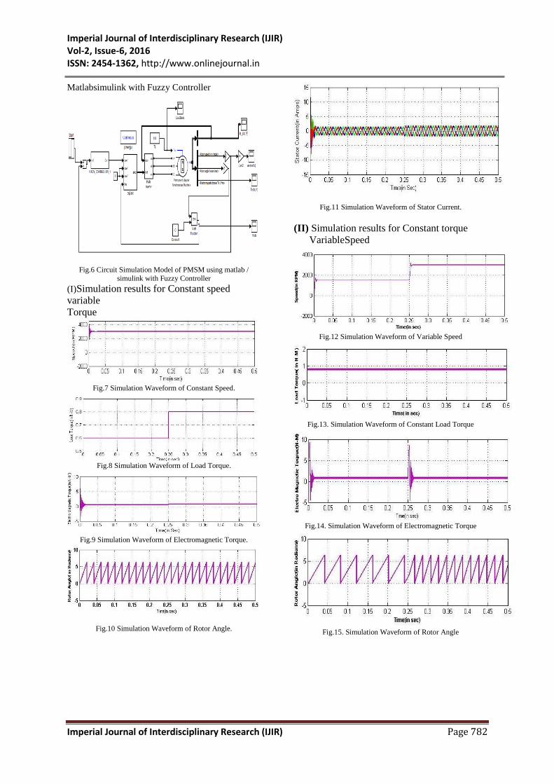
(I)Simulation results for Constant speed
variable
Torque
Fig.7 Simulation Waveform of Constant Speed.
Fig.8 Simulation Waveform of Load Torque.
Fig.9 Simulation Waveform of Electromagnetic Torque.
Fig.10 Simulation Waveform of Rotor Angle.
Fig.11 Simulation Waveform of Stator Current.
(II) Simulation results for Constant torque
VariableSpeed
Fig.12 Simulation Waveform of Variable Speed
Fig.13. Simulation Waveform of Constant Load Torque
Fig.14. Simulation Waveform of Electromagnetic Torque
Fig.15. Simulation Waveform of Rotor Angle

Imperial Journal of Interdisciplinary Research (IJIR) Vol-2, Issue-6, 2016 ISSN: 2454-1362, http://www.onlinejournal.in
Imperial Journal of Interdisciplinary Research (IJIR) Page 783
Fig.16. Simulation Waveform of stator Current
Case-2:Circuit Simulation Model of
PMSM usingMathematical Model with
Fuzzy Controller
Fig.17 Circuit Simulation Model of PMSM using Mathematical
Model with Fuzzy Controller
(I) Simulation results for Constant speed
variable
Torque
Fig.18. Simulation Waveform of Constant Speed
Fig.19. Simulation Waveform of Load Torque
Fig.20. Simulation Waveform of Electromagnetic
Torque
Fig.21. Simulation Waveform of Rotor Angle
Fig.22. Simulation Waveform Stator Current
(II) Simulation results for Constant torque
Variable Speed
Fig.23 Simulation Waveform of Variable Speed
Fig.24. Simulation Waveform of Constant Load Torque

Imperial Journal of Interdisciplinary Research (IJIR) Vol-2, Issue-6, 2016 ISSN: 2454-1362, http://www.onlinejournal.in
Imperial Journal of Interdisciplinary Research (IJIR) Page 784
Fig.25. Simulation Waveform of Electromagnetic Torque.
Fig.26. Simulation Waveform of Rotor Angle.
Fig.27. Simulation Waveform of Stator Current.
VI .CONCLUSION
An advanced simulation model of closed loop PM
Synchronous Motor drive system has been
developed by utilizing the mathematical model of
PM Synchronous Motor and hysteresis current
controlled three phase VSI inverter. The developed
simulation system model has been verified by
circuit simulation model of the similar scheme
which shows the accuracy of the developed model.
It has been observed that the torque and the stator
flux ripples are significantly reduced and a constant
switching frequency is achieved in fuzzy controller.
Other improvements observed in fuzzy controller
are the reduction in phase current distortion, fast
torque response and increase in efficiency of the
drive. This developed model can be well utilized in
the design and development of closed loop PM
synchronous motor drives system for
experimenting with different control algorithms
and topological differences but with a much
reduced computational time and memory size
REFERENCES
[1] R. Krishnan, “Permanent Magnet Synchronous and
Brushless DC Motor Drives,” CRC Press, Taylor
and Francis Group. ISBN-978-0-8247-5384-9.
[2] PragasanPillay, R.Krishnan, “Modeling Simulation
and Analysis of Permanent Magnet Motor Drives,
Part-I: The Permanent-MagnetSynchronus Motor
Drive”,IEEE vol.25, no.2, March/April 1989
[3] Paul C.Krause, Oleg Wasynczuk, Scott D.Sundhoff,
“Analysis of Electric Machinery and Drive
Systems,” IEEE Press Power Engineeringsociety
ISBN-0-471-14326-X
[4] Byounk-Kuklee, MehrdadEhsani, “Advanced
simulation model for brushless DCmotor drives,”
Electric Power Corporation and systems31:84-868-
2003, copyright@ Taylor and Francis Inc
[5] H, MadadiKojabad, G.Ahrabian, “Simulation and
analysis of the interior permanent magnet
synchronous motor as a brushless AC-
drive,”Science direct / Simulation practice and
theory 7(2000) 691-707.
[6] BimalK.Bose, “Modern Power Electronics and AC
Drives,” Prentice Hall ISBN-0-13-016743-6.
[7] PragasanPillay, R.Krishnan.” Modeling of
Permanent Magnet Motor Drives”, IEEE vol.35,
no.4, November 1988. 2014 International
Conference on Circuit, Power and Computing
Technologies [ICCPCT].
[8] M.T. Benchouia, Zouzou S.E., Golea A., Ghamri
A., “Modeling and Simulation of Variable Speed
Drive System with Adaptive Fuzzy Controller
Application to PMSM”, IEEE International
Conference on Industrial Technology (ICIT), pp 683
– 687, December, 2004.
[9] Sung Yu J., Mo Hwang S., Yuen Won C.,
“Performances of Fuzzy – Logic – Based Vector
Control for Permanent Magnet Synchronous Motor
Used in Elevator Drive System”, The 30th Annual
Conference of the IEEE Industrial Electronics
Society, pp 2679 – 2683, November, 2004.
[10] Nour M., Aris I., Mariun N., Mahmoud S.,” Hybrid
Model Reference Adaptive Speed Control for
Vector Controlled Permanent Magnet Synchronous
Motor Drive” IEEE Power Electronics and Drive
System, pp 618 – 623, April, 2006.
[11] Rahideh A., Rahideh A., Karimi M., Shakeri A.,
Azadi M., “High Performance Direct Torque
Control of a PMSM using Fuzzy Logic and Genetic
Algorithm”, IEEE International Conference on
Electric Machines and Drives System, pp 932 – 937,
May, 2007.