Identification Procedures as Tools for Fault Diagnosis of Rotating
10
International Journal of Rotating Machinery 1995, Vol. 1, No. 3-4, pp. 267-275 Reprints available directly from the publisher Photocopying permitted by license only (C) 1995 OPA (Overseas Publishers Association) Amsterdam B.V. Published under license by Gordon and Breach Science Publishers SA Printed in Singapore Identification Procedures as Tools for Fault Diagnosis of Rotating Machinery DIPL.-ING. SUSANNE SEIBOLD Lehrstuhl ffir Technische Mechanik, Universitt Kaiserslautern, D-67653 Kaiserslautern, Germany PROF. DR.-ING. CLAUS-PETER FRITZEN Institut ffir Mechanik und Regelungstechnik, Universitat-GH ,Siegen, D-57076 Siegen, Germany System identification procedures offer the possibility to correct erroneous models, based on measurement data. Recently, this conventional field of application is being extended to fault detection and system diagnosis. In contrast to conventional approaches, identification procedures try to establish an unequivocal relation in between the damage and specific mechanical parameters, based on a suitable model. Furthermore, they can be employed during normal operation of the machinery. In this paper, several identification procedures on the basis of the Extended Kalman Filter are introduced and employed for model-based fault detection. Their feasability is proved by several examples. First, it is shown that the crack depth of a simulated Jeffcott-rotor can be calculated correctly. Then, the procedures are utilized to determine the crack depth of a rotor test rig. Finally, it is proved that identification procedures can be employed for the determination of unbalances without having to apply test masses. Key Words Fault diagnosis; System identification; Kalman filtering; Damage supervising; Combined state and parameter estimation; Balancing INTRODUCTION onitoring and diagnosis of machinery is a field which is receiving increasing interest. Current practices and trends are described e.g. by Eshleman [1990], Randall [1990], Jonas [1992] and E1-Shafei [1993]. Very often, special attention is being focused on the detection of cracks: Wauer [1990] gives a concise overview about the research performed in the area of modeling the dynamics of cracked rotors and detection procedures. A possibility to detect a crack is e.g. the monitoring of the rotor vibrations and the comparison to the results of a suitable analytical model, Muszynska [1982], or to a reference signal, Imam [1983]. In contrast to approaches utilizing signal analysis, model-based procedures are being developed, which try to establish an unequivocal relation in between the damage (not necessarily a crack) and specific mechanical parameters. To achieve this, a-priori knowledge like e.g. a mathematical description of the system dynamics is employed. Waller and Schmidt [1990] describe a modal observer suitable for the application to MDOF systems. Another method is presented by S6ffker and Bajkowski [1991], which makes use of the state observer for nonlinear systems developed by Mfiller [1990]. Struc- tural similarities to the approach of Fritzen and Seibold 1990] can be shown, where the Extended Kalman Filter is applied to shaft crack detection. In this paper, time domain identification algorithms, based on the Extended Kalman Filter (EKF) and the Instrumental Variables method (IV), and a modification of the EKF in analogy to Mtller 1990] are presented and applied to fault diagnosis of rotating machinery. Specific advantages are the direct processing of time domain measurements, without the necessity of a transformation to frequency domain, and the establishing of a physically meaningful relation in between the damage and a certain parameter. Furthermore, unknown states are recon-
Transcript of Identification Procedures as Tools for Fault Diagnosis of Rotating

International Journal of Rotating Machinery1995, Vol. 1, No. 3-4, pp. 267-275Reprints available directly from the publisherPhotocopying permitted by license only
(C) 1995 OPA (Overseas Publishers Association)Amsterdam B.V. Published under license byGordon and Breach Science Publishers SA
Printed in Singapore
Identification Procedures as Tools for Fault Diagnosisof Rotating Machinery
DIPL.-ING. SUSANNE SEIBOLDLehrstuhl ffir Technische Mechanik, Universitt Kaiserslautern, D-67653 Kaiserslautern, Germany
PROF. DR.-ING. CLAUS-PETER FRITZENInstitut ffir Mechanik und Regelungstechnik, Universitat-GH ,Siegen, D-57076 Siegen, Germany
System identification procedures offer the possibility to correct erroneous models, based on measurement data. Recently,this conventional field of application is being extended to fault detection and system diagnosis. In contrast to conventionalapproaches, identification procedures try to establish an unequivocal relation in between the damage and specific mechanicalparameters, based on a suitable model. Furthermore, they can be employed during normal operation of the machinery. Inthis paper, several identification procedures on the basis of the Extended Kalman Filter are introduced and employed formodel-based fault detection. Their feasability is proved by several examples. First, it is shown that the crack depth of asimulated Jeffcott-rotor can be calculated correctly. Then, the procedures are utilized to determine the crack depth of a rotortest rig. Finally, it is proved that identification procedures can be employed for the determination of unbalances withouthaving to apply test masses.
Key Words Fault diagnosis; System identification; Kalman filtering; Damage supervising; Combined state and parameterestimation; Balancing
INTRODUCTION
onitoring and diagnosis of machinery is a fieldwhich is receiving increasing interest. Current
practices and trends are described e.g. by Eshleman[1990], Randall [1990], Jonas [1992] and E1-Shafei[1993]. Very often, special attention is being focused onthe detection of cracks: Wauer [1990] gives a conciseoverview about the research performed in the area ofmodeling the dynamics of cracked rotors and detectionprocedures. A possibility to detect a crack is e.g. themonitoring of the rotor vibrations and the comparison tothe results of a suitable analytical model, Muszynska[1982], or to a reference signal, Imam [1983].
In contrast to approaches utilizing signal analysis,model-based procedures are being developed, which tryto establish an unequivocal relation in between thedamage (not necessarily a crack) and specific mechanicalparameters. To achieve this, a-priori knowledge like e.g.
a mathematical description of the system dynamics isemployed. Waller and Schmidt [1990] describe a modalobserver suitable for the application to MDOF systems.Another method is presented by S6ffker and Bajkowski[1991], which makes use of the state observer fornonlinear systems developed by Mfiller [1990]. Struc-tural similarities to the approach of Fritzen and Seibold1990] can be shown, where the Extended Kalman Filter
is applied to shaft crack detection.In this paper, time domain identification algorithms,
based on the Extended Kalman Filter (EKF) and theInstrumental Variables method (IV), and a modificationof the EKF in analogy to Mtller 1990] are presented andapplied to fault diagnosis of rotating machinery. Specificadvantages are the direct processing of time domainmeasurements, without the necessity of a transformationto frequency domain, and the establishing of a physicallymeaningful relation in between the damage and a certainparameter. Furthermore, unknown states are recon-
268 S. SEIBOLD AND C.E FRITZEN
structed and possible parameter changes can be moni-tored during normal operation of the machinery. Thesemodel-based procedures are sensible supplementals ofthe approved tools for fault diagnosis and their feasabil-ity is explained by two examples: a simulated Jeffcott-rotor, where the crack depth is identified, and a rotor testrig, where the depth of a crack and the unbalance aredetermined.
THE INSTRUMENTAL VARIABLESMETHOD (IV)
The IV-method is a parameter identification procedurewhich yields consistent and asymptotically unbiasedestimates, requiring only little information about thenoise characteristics. For a general description seeDurbin [1954]. Wong and Polak [1967] and Young1970] apply the IV-method as a purely statistical proce-dure to control problems. The IV-method can be derivedfrom the well known Least Squares normal equations
ATb AT A PLS 0, (1)
A being the coefficient matrix. Eq. (1) can be estab-lished for problems that are linear in the parameters. Theestimated parameters /0LS, which result from (1), arebiased, and the expected values of/LS are e
E LS} P0 + E{(ATA) -1 ATe} (2)
Pk+l [I--/kA’+l]Pk" (6)
In the case of a mechanical system, assuming thatdisplacements x are measured, we need the completeinformation about x and its derivatives X and X and todetermine the coefficient matrix A and the InstrumentalVariables matrix W. These derivatives could be calcu-lated by means of numerical differentiation. But, thismight lead to bad results, especially if the level ofmeasurement noise is high. Another possibility is to
apply spline approximation, which is a better choice. Ofcourse, this might cause problems if stochastic signalsare dealt with. In this paper, it will be shown how theExtended Kalman Filter can be employed, cf. Seibold et
al. [1993].
THE EXTENDED KALMAN FILTER (EKF)
The EKF is based on the Kalman Filter (KF), which wasderivated by Kalman [1960] based on the concept oforthog0nal projection, as an optimal filter for linearsystems. But, as for many nonlinear problems cannot belinearized globally, suitable algorithms have to be devel-oped. Jazwinski [1970] describes, how the KF has to bemodified so that it can be applied as EKF to nonlinear
systems. The basic idea is to linearize at each time steparound a reference trajectory. In this way, the globalnonlinearity is maintained.The motion of a mechanical system can be described
by the differential equation
Po are the true parameters and is the error vector. The
bias EI(ATA)-1 ATewill not vanish, because A andare usually correlated. Nevertheless, unbiased estimatescan be produced if an Instrumental Variable matrix Wwith certain properties is introduced. According to Young[1970], the elements of W should be highly correlatedwith the unobservable noise-free responses of the sys-tem, but totally uncorrelated with the noise, so that
E lwTfi --0 and EIWTA} is existing and nonsingular.Then, unbiased estimates/3iv are be obtained by
PIV (WTA) 1WTb" (3)
Wong and Polak [1967] and Young [1970] give arecursive version of the IV-method (RIV):
/}k+l 10k -k- k[Yk+l -A+I/}k]’ (4)
k [akT+lPkWk+l -t- I]-lpkWk+l, (5)
M (x,p,t) g(x,2,u,p,t), (7)
M being the mass matrix which might depend on thedisplacements x and time t. g is the vector of generalizedforces and moments, including elastic, damping, gyro-scopic forces etc., and u is the input vector.The EKF is a recursive time domain procedure suit-
able for the identification of nonlinear systems. Systemdisturbances as well as measurement noise can beconsidered and a state space formulation of the differen-tial equations of motion is required. In the case ofmechanical systems, the state space vector z consists ofthe displacements x and the velocities .. For the purposeof simultaneous state and parameter estimation, z isextended by the unknown parameters p:
T TzT= (XT, )T, pT) (ZxT, ZV, Zp). (8)
Applying state space notation, the vibrations of a me-chanical system can be described by the followingequation, assuming time constant parameters:

FAULT DIAGNOSIS 269
2 fv M-l(zx,t)g(zx,zv,zp,u,t)p 0
(9)
Considering discrete time steps tk, the relation in be-tween the observed measurement data Yk and the statevariables zk at time t is
Yk CZk -’[- nk. (1 O)
In our case, C is a constant matrix and nk denotes themeasurement noise. The EKF consists of a predictor anda corrector part, with the prediction
tk+
k + 1/k ?k "1- ff (?k, tk, Uk) dt (11)
tk
basing on the model equations f. The correspondingcovariance matrix is
Pk+ 1/k APA + Q. (12)
Employing new measurements Yk+l, the prediction (11)is corrected by
k+l ?k+l/k -I- Kgk+ (Yk+l --Ck+l/k), (13)
and the corrected covariance matrix is
TPk+l (I- Kgk+lC)Pk+l/k([- Kgk+lC)T + Kgk+lRKgk+ 1.(14)
The Kalman gain matrix Kg is calculated by
Kgk+ Pk+l/kCT(CPk+l/kCT t- Rk)-1. (15)
The initial values are normally distributed, with mean Zoand covariance Po. Ak is the time discrete system matrixand results from a local linearization of the systemequations f around the estimated trajectory at each timestep tk:
Ak expAkat + AkAt + AkAt2/2! + ..." At k +l
AkOf0ZT
--tk,
(16)
Z- k" (17)
It is important to note that in this way, the globalnonlinearity is maintained. Q*k is the discrete system
noise covariance matrix and has to be calculated at eachtime step tk, tOO. Rk is the covariance matrix of themeasurement noise nk. Therefore, the confidence in theinitial values Zo, in the system equations f as well as inthe measurements Yk can be expressed by means of thecovariance matrices P, Q and R, respectively.
THE COMBINED ALGORITHM REKFIV
The EKF is very time consuming and might, in certaincases, show poor convergence properties if it is used forcombined state and parameter estimation, Ljung [1979].But, being used exclusively as a state estimator, the EKFwill perform well and provide us with the advantage ofthe reconstruction of unknown states and dofs. There-fore, the idea is to combine EKF and RIV in a way thatthe EKF is used as a state estimator to produce theInstrumental Variables for the RIV. We propose toproceed in the following manner, see figure 1:
1. Estimate the initial values by recursive Least Squares(RLS). In the case of measured displacements x,calculate the lacking velocities 2 and accelerations Xby spline approximation. This leads to a completematrix A.
2. Use the EKF as a state estimator only, i.e. omit linethree in eq. (9). The parameters are set to the initialvalues calculated above and remain constant.
3. The filtered time series produced by the state-EKFare used to build up the IV-matrix W. The lackingaccelerations can be derived via the system equationsf, see eq. (9). In the case of system noise respectively
input u
output .Y__k
initial information aboutparameters P0 system noise
EKFfixed parameters --Pi
state estimation
parameter P--iq
u_. RIVrecursive
parameter estimationnew parameter set Pil
state vector z_ k
PM
FIGURE Recursive combination of EKF and RIV: REKFIV.
270 S. SEIBOLD AND C.P. FRITZEN
erroneous models, the covariance matrix Q iscalculated.
4. Now, with complete matrices A and W, an improvedset of parameters p is determined.
5. Repeat from 2. on as long as measurement data isavailable or until the parameters converge.
THE MODIFIED EXTENDED KALMANFILTER (MEKF)
The EKE (11)-(17), was developed for stochastic dy-namic systems and shows a structural similarity to thestate observer, which is known from control theory.MOiler 1990] designed a state observer for deterministicsystems in order to determine unknown nonlinearities.These are interpreted as "external disturbances", whichare characterized by a suitable model. In analogy, theEKF is modified in such a manner that it can reconstructthese "external disturbances", Seibold et al. [1993],without the necessity to model their dynamics, S6ffker etal. [1994]. Essentially, the state space vector z has to beextended by the "external disturbances" and their timederivatives (I’T,1)T):
zw (xT,ff,vT,9T). (18)
The EKF-equations can be used like being described in(11)-(17). The coupling in between the linear part of thesystem (xT,ff) and the "exogeneous system" (vT,T) isdone via the prediction (11), where the linear part of thesystem has to be supplemented by the exogeneoussystem, which was calculated in the preceding time step.
EXAMPLES
Simulated Example: Jeffcott Rotor with aTransversal Crack
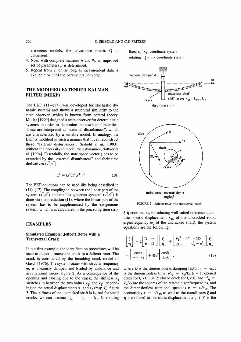
In our first example, the identification procedures will beused to detect a transverse crack in a Jeffcott-rotor. Thecrack is considered by the breathing crack model ofGasch 1976]. The system rotates with circular frequencyto, is viscously damped and loaded by unbalance andgravitational forces, figure 2. As a consequence of theopening and closing due to the crack, the stiffness kswitches in between the two values kl and kz, depend-ing on the actual displacements x and x2 (resp. {), figure3. The stiffness of the uncracked shaft is ko and for smallcracks, we can assume k2 ko k. In rotating
fixed x- x2- coordinate system
rotating - rI- coordinate system
viscous damper d
J m.a,s,,sless sh,aftcrack stiffnesses k,, k,2, k n
disc (mass m)
unbalance: eccentricity eanglel3
FIGURE 2 Jeffcott-rotor with transversal crack.
<q-coordinates, introducing well-suited reference quan-tities (static displacement xls of the uncracked rotor,eigenfrequency too of the uncracked shaft), the systemequations are the following:
[ cosvt ] v2[c.os] (19)-sin vtJ+
I_ sin0
where D is the dimensionless damping factor, a" toois the dimensionless time, v2i ko/ko (i 1" openedcrack for > 0; 2: closed crack for < 0) and v
k/ko are the squares of the related eigenfrequencies, andthe dimensionless rotational speed is v to/too. Theeccentricity e e/xls as well as the coordinates and
xl are related to the static displacement xls. (..)’ is the

FAULT DIAGNOSIS 271
F
k2
F
k k0
FIGURE 3 Relation in between force and displacement.
derivative with respect to "r. The switching of thesuffness k () can be expressed by
The equations of motion (22) can be formulated in adifferent way, denoting
(11 )k k2 -I-- (kl k2 + -’rr arctan (C0) ;CO > 0,
(20)
xT [Xl/Xls x2/xls]: (24)
x" + 2Dx’ + x f(’r) v(’r). (25)
cf. Fritzen, Seibold [1990], and the decreasing of thestiffness due to the crack is described by the crack factorr;
r -1 -1. (21)
Transforming (19) to fixed Xl-X2-coordinates yields
X2/X -" 2D + S +S [-X2/X1s [--X2/X1s
-sin ur cos ur -sinm Ax/xls
v()
[1] e [ cos arr cos [3 sin arr sin [3 ] (22)0 Xls [ sin art cos [3 cos v-r sin [3
using the relation
A + arctan(C0) (23)r+l
The linear part of the equations of motion is on the lefthand side of (24), and on the right hand side are theexcitations f(’r) and the nonlinear part v(’r), which can beinterpreted as additional forces due to the crack. Thedynamic behaviour is simulated by numerical integrationof (22). The parameters are set to D 0.011, v 0.45,a" 0.01, e 0.01 and [3 0. The relation of the crackfactor r to the crack depth can be derived e.g. accordingto Mayes and Davies [1984]: r 0.01 corresponds to acrack depth in percentage of the diameter of the shaft of19%. On the basis of measured displacements X and x2,
EKF as state and parameter estimator, REKFIV andMEKF are employed to detect the depth of the crack.
For the application of EKF and REKFIV, the knowl-edge of the crack model v(’r), eq. (22), is assumed. EKFand REKFIV calculate a crack factor r 0.00995 resp.r 0.01005, figure 4. The initial parameters were set toro 0, which implies that no crack is present. Incontrast to this, the calculations with the MEKF can beperformed without the knowledge of a crack model, i.e.the exogeneous system v(’r) does not have to be struc-tured. The result of the MEKF is shown in figure 5,where it is compared to the true values v l(’r) according toeq. (22). This exogeneous system can be interpreted asnonlinear forces due to the crack. Except for smalldeviations at the first time steps, the two curves areidentical. The quantitative result of r 0.01, of course,can only be derived by a model of the crack, in this case

272 S. SEIBOLD AND C.R FRITZEN
crack factor0,07
0,06
0,05
0,04
0,03 REKFIV
0,02
0,01
0,000 500 1000 1500 2000 2500 3000 3500 4000
time steps
FIGURE 4 Identification of the crack factor by EKF and byREKFIV in comparison to the true value 0.01; simulated example.
according to eq. (22). Furthermore, this is supplementedby a qualitative description of the nonlinearity: theopening (vl(’r) > 0) and closing (vl(’r) 0) of the crackcan be seen in figure 5, too.The EKF can be modified to estimate time variable
parameters, i.e. in this case time dependent stiffnesses, sothat a crack model is not a prerequisite for the calcula-tions. In the EKF-equation (12), the covariance matrix ofsystem noise Q has to be set to adequate values. Figure6 shows the identification of one of the time varyingstiffness parameters. Like in figure 5, the opening (Cl <1) and closing (Cll 1) of the crack can be seen. Theresults correspond to the true crack factor r 0.01 andare compared to the true slope of the stiffness c
cos2 v’rA, see eq. (22). The two curves plottet in figure6 are almost identical.
Rotor Test Rig" Identification of the Crack Depth
The rotor test rig, figure 7, consists of a long, thin shaftof 18 mm diameter on hinged supports. A disc ismounted in the middle. Initiated by a slot with a depth of2 mm, a crack of mm is introduced, so that the totaldepth of the damage is 3 mm respectively 17% of the
exogeneous system0,012
0,01
0,008
0,006
0,004
0
0 500 1000 1500 2000 2500
time steps
3000 3500
FIGURE 5 Identification of the nonlinear forces (exogeneous system)due to the crack by MEKF, in comparison to the true slope of vl(’r)"simulated example.
1,002
1,000
0,998
0,996
0,994
0,992
0,990
stiffness c 11
0 1000 2000 3000 4000
time steps
FIGURE 6 Identification of the time varying stiffness c l(a-) incomparison to the true slope; simulated example.
FIGURE 7 Rotor test rig.

FAULT DIAGNOSIS 273
diameter of the shaft. Figure 8 shows the fractured crosssection. A beach mark, which results in a dark line on 0,35
the crack face, was set by applying a static overload in 0,3
order to be able to relate the crack depth to the 0,_5measurements of the horizontal and vertical
0,2displacements of the disc. They were taken duringstationary operation at a rotational speed of 780 rev/min. 0,5
For the identification, the system was modeled 0,1
according to eq. (22). But, of course, the dynamics of 0,05
the test rig cannot be completely described by these 0
equations, so that the covariance matrix of system noiseQ, eq. (12), has to be set to adequate values.REKFIV and EKF estimate crack factors r 0.012
resp. r 0.0178 which correspond to a depth of thecrack of 19.5% resp. 22.5%, Mayes and Davies [1984].The damage is overestimated, probably caused by the
crack factor
0 5OO 1000 15O0
time steps
FIGURE 9 Identification of the crack factor by REKFIV; test rig.
Rotor Test Rig: Identification of the Unbalancewithout Test Masses
initiating slot, which prevents a complete closing of the In the last example, EKF and REKFIV are utilized tocrack surface. Figure 9 shows the identification of r by determine the unbalance of the test rig described in theREKFIV. The oscillations around the final value of r preceding chapter, with the modification that the diam-
eter of the (undamaged) shaft is 12 mm. Again, thehorizontal and vertical vibrations of the disc are mea-sured during stationary operation. The system was mod-eled according to eq. (22), setting v(a’) 0. Table I showsthe identified values of the unbalance parameters e and [3and compares them to the results of a determination withtest masses. The identification of the parameters by EKFis shown in figure 11.
0.012 may be motivated by the fact, that the relativelylong and thin shaft is somewhat prebent.The calculations of the MEKF, figure 10, again
provide us with a quantative result (r 0.013; thiscorresponds to a crack depth of 20%) and a qualitativeresult: the crack opens in the range v l(’r) > 0 and theassumption that the crack surface really does not closecompletely is confirmed, because there is no range V l(a-)
0 (compare to figure5).
FIGURE 8 Fractured cross section and beach mark.
exogeneous system
0,025
0,020
0,0,
0,000
-0,005
-0,010
-0,0150 500 1000 1500
time steps
FIGURE 10 Identification of the nonlinear forces (exogeneous sys-tem) v, (’r) due to the crack by MEKF; test rig.
TABLECalculation of the unbalance of the test ig
EKF 0.073 0.11 radREKFIV 0.074 0.07 radCalculation using test masses 0.086 0 rad

274 S. SEIBOLD AND C.P. FRITZEN
parameter0,50
0,00
-0,50
-1,00
-1,50500 1000 1500 2000 2500 3000 3500
time steps
FIGURE 11 Identification of the unbalance parameters e and [3 byEKF; test rig.
CONCLUSIONS
System identification procedures offer the possibility tocorrect erroneous models, based on measurement data.Recently, this conventional field of application is beingextended to fault detection and system diagnosis. Incontrast to conventional approaches, identification pro-cedures try to establish an unequivocal relation in be-tween the damage and specific mechanical parameters,based on a suitable model. Furthermore, they can beemployed during normal operation of the machinery.
In this paper, three system identification procedureswere presented:
1. EKF: the Extended Kalman Filter as state andparameter estimator,
2. REKFIV: a recursive combination of the EKF asstate estimator and the Instrumental Variablesmethod,
3. MEKF: a modification of the EKF in analogy to thestate observer designed by Mtiller [1990].
The feasability of the procedures for model-basedfault detection of rotating machinery was proved byseveral examples. First, the crack depth of a simulatedJeffcott-rotor was calculated correctly. In addition, theresults of the MEKF yielded a qualitative assertion aboutthe character of the damage. Then, the three procedureswere successfully applied to a rotor test rig, in order todetect the crack depth. A supplementary information wasobtained: the crack surface did not close completely dueto the initiating slot. Finally, it was shown that systemidentification procedures can be employed for the deter-mination of unbalances without test masses.
In future projects, the algorithms will be extended insuch a manner that they can be applied to largerstructures modeled by finite elements.
Acknowledgement
The development of the combined algorithm REKFIV and the test rigis part of a project supported by the Deutsche Forschungsgemeinschaft(DFG), project no. Ha 1487/3-2.
Nomenclature
E(...) expected value of...x vector (true value)
vector (estimated value)derivative of x with respect to
x’ derivative of x with respect to "r
x"r transpose of xA system matrixC measurement matrixI unity matrixK Kalman gain matrix
p vector of parametersP covariance matrixQ covariance matrix of the system noiser crack factorR covariance matrix of the measurement noise
timeu vector of inputsv vector of the external disturbancesW Instrumental Variables matrix
y measurement vector (outputs)z state space vector
error vector
,3 related eccentricity and angle"r dimensionless time
References
Durbin, J., 1954. Errors in Variables, Revue de l’lnstitut Internationalde Statistique, Vol. 22, pp. 23-32.
EL-Shafei, A., 1993. Measuring Vibrations for Machinery Monitoringand Diagnostics, Shock and Vibration Digest, Vol. 25, No. 1, pp.3-14.
Eshleman, R.L., 1990. Detection, Diagnosis and Prognosis: an Evalu-ation of Current Technology, Proc. 44th Meeting of the MechanicalFailures Prevention Group, Virginia Beach, VA, pp. 33-42.
Fritzen, C.-P. and Seibold, S., 1990. Identification of Mechanical
Systems by Means of the Extended Kalman Filter, Proc. 3rdInternational IFToMM Conf. on Rotordynamics, Lyon, France, pp.423-429.
Gasch, R., 1976. Dynamic Behaviour of a Simple Rotor with a
Cross-Sectional Crack, Conference on Vibrations in Rotating Ma-chinery, IMechE Conference Publications, paper C178/76, Universityof Cambridge.
Imam, I., 1983. Method for on-line Detection of incipient Cracks inTurbine-Generator Rotors, US patent 4, 408, 294.
Jazwinski, A.H., 1970. Stochastic Processes and Filtering Theory,Academic Press, New York.
Jonas, O., 1992. Diagnostic Monitoring--An Overview, Power, 136,(1), pp. 61/108.
Kalman, R.E., 1960. A new Approach to Linear Filtering and PredictionProblems, Trans. ASME Series D, Journal ofBasic Engineering, Vol.82, pp. 35-45.
Ljung, L., 1979. Asymptotic Behaviour of the Extended Kalman Filteras a Parameter Estimator for Linear Systems, IEEE Trans. on
Automatic Control, Vol. AC-24, No. 1, pp. 36-50.

FAULT DIAGNOSIS 275
Mayes, I.W. and Davies, W.G.R., 1984. Analysis of the Response of a
Multi-Rotor-Bearing System Containing a Transverse Crack in aRotor, Journal of Vibration, Acoustics, Stress and Reliability in
Design, paper 83-DET-84, pp. 139-145.MOiler, P.C., 1990. Indirect Measurements of Nonlinear Effects byState Observers, IUTAM-Symposium on Nonlinear Dynamics in
Engineering Systems, Universitit Stuttgart, Springer-Verlag, Berlin,pp. 205-215.
Muszynska, A., 1982. Shaft Crack Detection, Proc. 7th MachineryDynamics Seminar, Edmonton, Canada, pp. 4.0-4.49.
Randall, R., 1990. Introduction to Condition Monitoring, Acoustics
Australia, 18(1), pp. 15-18.Seibold, S., S6ffker, D. and Fritzen, C.-P., 1993. ModellgesttitzteDetektion von Wellenrissen, Dynamische Probleme--Modellierungund Wirklichkeit, Mitteilung des Curt-Risch-Institutes der UniversitiitHannover, Eds. H.G. Natke, H.K. T6nshoff, G. Meltzer, pp. 309-328.
Seibold, S., Fritzen, C.-P. and Leifeld, A., 1993. A Combined State andParameter Estimator Applied to Fault Detection, IUTAM-Symposium
on Identification of Mechanical Systems, Universitiit Wuppertal,Springer Verlag, Berlin, Heidelberg, New York, to appear.
Stiffker, D. and Bajkowski, J., 1991. Crack Detection of a Rotor byState Observers, Proc. of the 8th IFToMM World Congress on theTheory of Machines and Mechanisms, Prag, pp. 771-774.
S6ffker, D., Yu, T. and Mtiller, EC., 1994. State Estimation of
Dynamical Systems with Nonlinearities by using Proportional-Inte-gral Observer, Int. J. of Sys. Sc., to appear.
Waller, H. and Schmidt, R., 1990. The Application of State Observersin Structural Dynamics, Mechanical Systems and Signal Processing,4(3), pp. 195-213.
Wauer, J., 1990. On the Dynamics of Cracked Rotors--a Literature
Survey, Applied Mechanics Revue, Vol. 43, No. 1, pp. 13-17.Wong, K.Y. and Polak, E., 1967. Identification of Linear Discrete Time
Systems Using the Instrumental Variables Method, IEEE Trans. on
Automatic Control, Vol. AC- 12, No. 6, pp. 707-718.Young, P., 1970. An Instrumental Variables Method for Real-Time
Identification of a Noisy Process, Automatica, 6, pp. 271-287.

International Journal of
AerospaceEngineeringHindawi Publishing Corporationhttp://www.hindawi.com Volume 2010
RoboticsJournal of
Hindawi Publishing Corporationhttp://www.hindawi.com Volume 2014
Hindawi Publishing Corporationhttp://www.hindawi.com Volume 2014
Active and Passive Electronic Components
Control Scienceand Engineering
Journal of
Hindawi Publishing Corporationhttp://www.hindawi.com Volume 2014
International Journal of
RotatingMachinery
Hindawi Publishing Corporationhttp://www.hindawi.com Volume 2014
Hindawi Publishing Corporation http://www.hindawi.com
Journal ofEngineeringVolume 2014
Submit your manuscripts athttp://www.hindawi.com
VLSI Design
Hindawi Publishing Corporationhttp://www.hindawi.com Volume 2014
Hindawi Publishing Corporationhttp://www.hindawi.com Volume 2014
Shock and Vibration
Hindawi Publishing Corporationhttp://www.hindawi.com Volume 2014
Civil EngineeringAdvances in
Acoustics and VibrationAdvances in
Hindawi Publishing Corporationhttp://www.hindawi.com Volume 2014
Hindawi Publishing Corporationhttp://www.hindawi.com Volume 2014
Electrical and Computer Engineering
Journal of
Advances inOptoElectronics
Hindawi Publishing Corporation http://www.hindawi.com
Volume 2014
The Scientific World JournalHindawi Publishing Corporation http://www.hindawi.com Volume 2014
SensorsJournal of
Hindawi Publishing Corporationhttp://www.hindawi.com Volume 2014
Modelling & Simulation in EngineeringHindawi Publishing Corporation http://www.hindawi.com Volume 2014
Hindawi Publishing Corporationhttp://www.hindawi.com Volume 2014
Chemical EngineeringInternational Journal of Antennas and
Propagation
International Journal of
Hindawi Publishing Corporationhttp://www.hindawi.com Volume 2014
Hindawi Publishing Corporationhttp://www.hindawi.com Volume 2014
Navigation and Observation
International Journal of
Hindawi Publishing Corporationhttp://www.hindawi.com Volume 2014
DistributedSensor Networks
International Journal of