Identification and Reduction of Piping-Vibrations under ... · PDF fileIdentification and...
30
165 410 MPA-shaker Welded seam 4 bolts Mounting position for dampers Mounting position for hangers 3180 600 approx. 2000 1680 4690 410 R300 1140 2720 60 1050 Authors: Frank Barutzki Christa Gurr-Beyer Gereon Hinz Klaus Kerkhof Joachim Schwenkkros 8 Identification and Reduction of Piping-Vibrations under Different Conditions Motivation Safe operation, availability and lifetime assessment of piping systems are of utmost concern for plant operators. Optimized plants and safe operation under changing sur- rounding and boundary conditons are of concern. Integrity assessment in these cases is to be performed and demonstrated in corresponding experiments. Main Results In a number of field and laboratory tests the feasibility of system identification and integrity assessment has been demonstrated. Uncertainties are considerably reduced by monitoring results and measures like vibration reduction.
Transcript of Identification and Reduction of Piping-Vibrations under ... · PDF fileIdentification and...
165
Chapter 8-x
410
MPA-shaker
Weldedseam
4 bolts
Mou
ntin
g po
sitio
nfo
r dam
pers
Mou
ntin
g po
sitio
nfo
r han
gers
3180 600
approx. 2000 1680
4690410
R300
1140
2720
60 1050
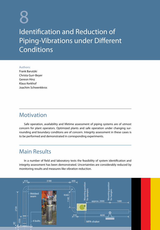
Authors:Frank BarutzkiChrista Gurr-BeyerGereon HinzKlaus Kerkhof Joachim Schwenkkros
8Identification and Reduction of Piping-Vibrations under Different Conditions
MotivationSafe operation, availability and lifetime assessment of piping systems are of utmost
concern for plant operators. Optimized plants and safe operation under changing sur-rounding and boundary conditons are of concern. Integrity assessment in these cases is to be performed and demonstrated in corresponding experiments.
Main ResultsIn a number of field and laboratory tests the feasibility of system identification and
integrity assessment has been demonstrated. Uncertainties are considerably reduced by monitoring results and measures like vibration reduction.
166
8 Identification and Reduction of Piping-Vibrations under Different Conditions
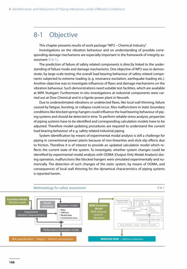
Excitation ModelVibration loads
Experimentvibration measurements
Model-updating System‘s model
Performance evaluation model
Risk quantification / fatigue / lifetime-consumption
/ Mass/ Stiffness/ Modal data/ Constitutive laws
NEW Excitation Model
NEW reduced level of
vibrations
REDUCED RISK − Lifetime-extension
Excitation ModelVibration loads
Experimentvibration measurements
Model-updating System‘s model
Performance evaluation model
Risk quantification / fatigue / lifetime-consumption
/ Mass/ Stiffness/ Modal data/ Constitutive laws
Methodology for safety assessment F.8-1
8-1 ObjectiveThis chapter presents results of work package “WP2 – Chemical Industry”. Investigations on the vibration behaviour and on understanding of possible corre-
sponding damage mechanisms are especially important in the framework of integrity as-sessment (F.8-1).
The prediction of failure of safety related components is directly linked to the under-standing of failure mode and damage mechanisms. One objective of WP2 was to demon-strate, by large scale testing, the overall load bearing behaviour of safety related compo-nents subjected to extreme loading (e. g. resonance excitation, earthquake loading etc.). Another objective was to investigate influences of flaws and damage mechanisms on the vibration behaviour. Such demonstrations need suitable test facilities, which are available at MPA Stuttgart. Furthermore in-situ investigations at industrial components were car-ried out at Dow Chemical and in a lignite power plant in Neurath.
Due to underestimated vibrations or undetected flaws, like local wall thinning, failure caused by fatigue, bursting, or collapse could occur. Also malfunctions in static boundary conditions like blocked spring-hangers could influence the load bearing behaviour of pip-ing systems and should be detected in time. To perform reliable stress analysis, properties of piping systems have to be identified and corresponding calculation models have to be adjusted. Therefore model-updating procedures are required to understand the current load bearing behaviour of e. g. safety related industrial piping.
System identification by means of experimental modal analysis is still a challenge for piping in conventional power plants because of non-linearities and stick-slip effects due to friction. Therefore it is of interest to provide an updated calculation model which re-flects the current state of the system. To investigate, whether system changes could be identified by experimental modal analysis with OOMA (Output Only Modal Analysis) dur-ing operation, malfunctions like blocked hangers were simulated experimentally and nu-merically. The detection of such changes of the static system, by means of OOMA, and consequences of local wall thinning for the dynamical characteristics of piping systems is reported herein.

167
Identification and Reduction of Piping Vibrations Using Dynamic Vibration Absorbers 8-2
0.2 0.60.4 1.0
Frequency ratio f/f0
Main systemwith TMD
Main system without TMD
1.40.8 1.2 1.6 1.8
Vibr
atio
n am
litud
e of
mai
n sy
stem
2
0
1.5
0.5
1
General effect of a vibration absorber – tuned mass damper (TMD) F.8-2
The use of tuned mass dampers is a rather new approach for reducing vibrations to avoid high cycle fatigue in piping systems. First design ideas for new passive vibration ab-sorbers were investigated in laboratory tests with a mock-up piping system. Thereafter an industrial piping system was investigated: This piping system is supported by a tall struc-ture fixed at the base. As a result, the steel building stiffness decreases with height. Large piping elbow forces act at the top of the building, which lead to large vibration ampli-tudes. Since both piping system and supporting structure exhibited these large vibration amplitudes, dampers or shock absorbers placed between them would prove less effective [Barutzki, 2009]. Therefore, special vibration absorbers, so called Tuned Mass Dampers (TMD) were developed for such piping systems. The first step to achieve the objectives mentioned above is to create an evaluation model on the basis of vibration analysis (ex-perimental modal analysis) and model-updating, as shown in F.8-1. Then a new excitation model with a reduced level of vibration – e. g. realized by vibration absorbers – shoud be created. The final evaluation model comprises reduced risk. Parts of this investigation have been described in [Hinz and Kerkhof, 2013] and [Dwenger, 2011].
8-2 Identification and Reduction of Piping Vibrations Using Dynamic Vibration Absorbers
Dynamic vibration absorbers are often used, e. g. [Meinhardt et al., 2008], to reduce the response of a vibration system to dynamic excitations and to increase the internal damping of an otherwise low damped vibration system. By attaching an auxiliary mass to a vibrating system by spring and damping devices absorber effects can be utilized, F.8-2. By vibrating out of phase with the main system counteracting forces are developed and energy is dissipated.

168
8 Identification and Reduction of Piping-Vibrations under Different Conditions
410
Mounting plate
MPA-shaker
Piping material:Nominal diameter:Nominal wall thickness:
15Mo 3 (1.5415)Da = 219.1 mmt = 17.5 mm
Anchor plate
Weldedseam
4 bolts
Mou
ntin
g po
sitio
nfo
r dam
pers
Mou
ntin
g po
sitio
nfo
r han
gers
∅ 1200
1000
3180
8770
600
approx. 2000 1680
4690410
R300
1340
1140
2720
60 1050
Dimension and construction of mock-up F.8-3
Today dynamic vibration absorbers can be found in easily excitable structures such as street and pedestrian bridges, terraces, chimneys or long-span floors. When excited with frequencies close to a natural frequency these usually slightly damped structures respond with large deflections, which are often sensed as uncomfortable, but which are some-times also dangerous and service life reducing. Large piping systems in power or indus-trial plants are also slightly damped, highly flexible and complex structures. The increase of system damping is often the only efficient way to reduce system responses to all kinds of dynamic excitations. Viscous dampers are often used for this purpose but they require a stiff support point. Especially in tall piping structures these stiff supports are missing and therefore the use of passive dynamic vibration dampers with efficient damping ca-pability is a promising approach to increase system damping and to solve the vibration problems in these systems. In general dynamic vibration absorbers consist of a mass that is elastically connected to the main structure by springs or pendulum systems. Additional dampers acting in parallel to the springs or pendulums dissipate the vibration energy and widen the working range of these elements. In case of large structures and depending on the critical mode shape to be dampened several absorbers can be installed along the structure to work in parallel.
8-2-1 Mock-up Tests with Vibration Absorbers (TMD)
Within [IRIS, 2012] and [Safepipes, 2008] different kinds of support components were mounted onto a mock-up and investigated by several project partners. Only one test se-ries will be reported herein, namely
//// Vibration analysis of the system without damping from vibration absorber and//// Vibration analysis using a newly developed passive vibration absorber.

169
Identification and Reduction of Piping Vibrations Using Dynamic Vibration Absorbers 8-2
Mode 2 Mode 3Mode 1
1.38 Hz (out-of-plane mode) 5.44 Hz (in-plane mode) 6.92 Hz (out-of-plane mode)
Mode 5 Mode 6Mode 4
8.62 Hz (in-plane mode) 10.63 Hz (out-of-plane mode) 23.61 Hz (in-plane mode)
Coarse FE model, Modes 1 to 6 F.8-4
The system consists of one fully clamped support at the anchor plate and a sliding support constructed by means of two vertical struts. The construction is shown in F.8-3.
In the first coarse finite element (FE) model the whole system with its nominal piping diameter and the quadratic anchor-plate, which is mounted onto the mounting plate with four anchors, was modelled altogether with 3D-Volume tetrahedron-elements by using the Finite Element Programme ABAQUS. The first six calculated eigenfrequencies and cor-responding mode-shapes are given in F.8-4. Within this calculation a concentrated mass for the MPA-shaker was taken into account.
For time history dynamic integrations an updated FE model was created with extend-ed beam elements so called ELBOW31 elements of the ABAQUS element library which take into account cross section ovalization. The element length is about 20 mm. The whole system was modelled with these elements. Therefore also the decay of the ovalization in adjacent beams following an elbow are taken into account as well. The conical cross sec-tion, close to the mounting, was divided into five beam elements.
The torsion stiffness of the pipe connection to the ground at the anchor-plate which itself is mounted to the concrete-mounting plate of the laboratory by four anchors was idealized by two torsion springs in the direction of the in-plane and out-of-plane bend-ing moment at the connection point of the pipe. These torsion springs and the pipe wall thicknesses – simulating the deviations to the nominal wall thicknesses – were the main parameters used for the model-updating process.
The measurement data of T.8-1 represent the free vibrations of the system without vibration absorber system without damping from the vibration absorber, but including the mounted MPA-shaker with a mass of 65 kg. The modal data was evaluated by means of Endevco accelerometers Type 7754-1000 and LMS Test.Lab 6A Operational Modal Analy-sis. The deviations between snap-back test results and impact hammer excitation results were less than 1 %. Therefore mean values of test series are given. All mode shapes cor-

170
8 Identification and Reduction of Piping-Vibrations under Different Conditions
Vibration absorber
Pipe
L
Mock-up system without damper but with MPA-shakerMode
No.Measurement *
[Hz]Elbow-element
model [Hz]Volume-element model (F.8-4) [Hz]
Type of mode
1 1.50 1.50 1.38 out-of-plane2 5.54 5.55 5.44 in-plane3 7.17 7.17 6.92 out-of-plane4 8.66 8.74 8.62 in-plane5 10.72 11.10 10.63 out-of-plane6 23.64 23.60 23.61 in-plane
* Mean value from snap-back and impact tests
Comparison Measurement – updated FE model, mock-up system without any damping components
T.8-1
Principal design of installed TMD F.8-5
respond with the calculated modes mentioned above. A comparison of measurement data with both, the updated Elbow-Element Model and the first design calculation for the system including a shaker mass of 65 kg is given in T.8-1. Measurements and calculations correspond well.
The principal design of the newly developed passive vibration absorber (TMD, tuned mass damper) for piping consists of a cantilever beam with a concentrated mass at the end, vibrating in a cylinder. The vibration velocities are damped by a special fluid within the cylinder as sketched in F.8-5. The bending eigenfrequency depends on the stiffness of the member which in turn depends on the length L of the cantilever beam. For tuning purposes this length L is adjustable.
For energy dissipation the vibrating mass of the dynamic absorber moves in a highly viscous fluid. The absorber can be attached to the pipe in various positions and the di-rection of the absorber vibration adapts itself to the motion of the pipe. Two different mounting positions of the vibration absorber (horizontal and vertical) on the mock-up were investigated during the laboratory experiments. The system with the horizontally mounted vibration absorber is shown in F.8-6. The results of the two manually controlled sine-sweep excitation tests up to 8 Hz (near second vertical natural frequency) and after-wards down to zero are shown in F.8-6. The results of the horizontal (blue) position are given by the dark blue line, the results of the vertical (green) position by the green line. The orange line represents the system response without vibration absorber. The results in F.8-6 show strong amplitude reductions in the vicinity of the frequency of mode 2. Also

171
Identification and Reduction of Piping Vibrations Using Dynamic Vibration Absorbers 8-2
3
2
1
0
–1
–2
–3Vert
ical
acc
eler
atio
n [g
]
4 6 7 [Hz]5
without vibration absorberwith vibration absorber verticalwith vibration absorber horizontal
0 20 60
Large scale laboratory tests [s]40 80 100 120
Acce
lera
tion
[g]
1.5
1.0
–1.0
–0.5
0
0.5
System response with (green) and without (blue) vibration absorber due to snap-back tests with 3 mm initial vertical deflections at the free end of the mock-up
Results of sine-sweep tests with two different mounting positions (above) of the vibration absorber
F.8-7
F.8-6
much more energy absorbing effects are observed when the absorber is mounted in the “blue” position. Mode 2 has larger vertical than horizontal displacements in this region.
The TMD only absorbs energy of mode 2. The next resonant excitation during run up, not visible in F.8-6, occurs at 7.8 Hz (10 % below mode 4 due to the added mass of the TMD), therefore current investigations are focussed on TMDs for absorbing two adjacent modes. F.8-7 shows a comparison of snap-back tests with and without TMD. F.8-7 consists of two different curves: The blue line shows the vertical displacements at the centre of the piping without TMD (cut of wire at t1 =7 s) and the green line shows the response of the system with TMD in blue position (cut of wire at t2=14 s). The effect of damping starts within the first cycle.
172
8 Identification and Reduction of Piping-Vibrations under Different Conditions
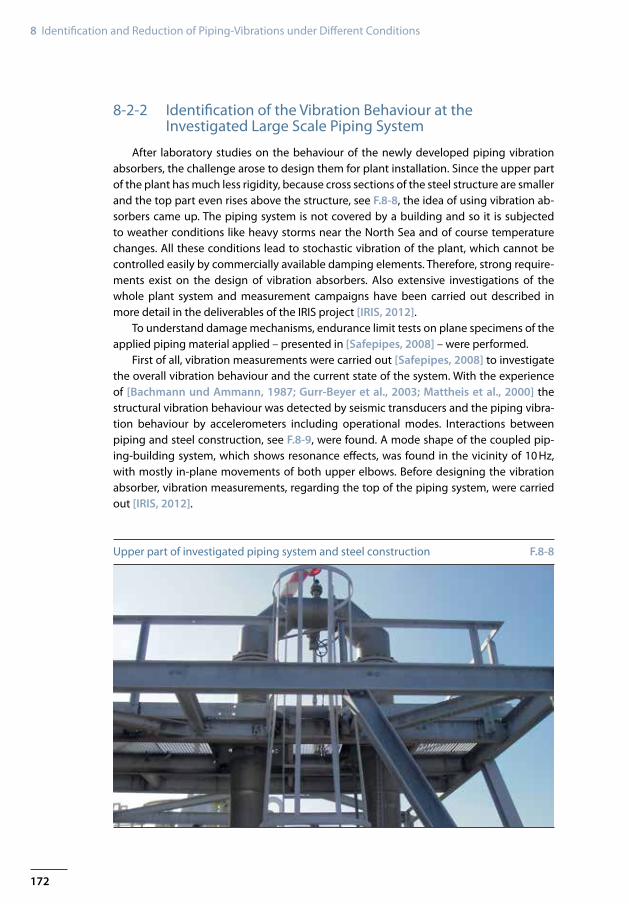
Upper part of investigated piping system and steel construction F.8-8
8-2-2 Identification of the Vibration Behaviour at the Investigated Large Scale Piping System
After laboratory studies on the behaviour of the newly developed piping vibration absorbers, the challenge arose to design them for plant installation. Since the upper part of the plant has much less rigidity, because cross sections of the steel structure are smaller and the top part even rises above the structure, see F.8-8, the idea of using vibration ab-sorbers came up. The piping system is not covered by a building and so it is subjected to weather conditions like heavy storms near the North Sea and of course temperature changes. All these conditions lead to stochastic vibration of the plant, which cannot be controlled easily by commercially available damping elements. Therefore, strong require-ments exist on the design of vibration absorbers. Also extensive investigations of the whole plant system and measurement campaigns have been carried out described in more detail in the deliverables of the IRIS project [IRIS, 2012].
To understand damage mechanisms, endurance limit tests on plane specimens of the applied piping material applied – presented in [Safepipes, 2008] – were performed.
First of all, vibration measurements were carried out [Safepipes, 2008] to investigate the overall vibration behaviour and the current state of the system. With the experience of [Bachmann und Ammann, 1987; Gurr-Beyer et al., 2003; Mattheis et al., 2000] the structural vibration behaviour was detected by seismic transducers and the piping vibra-tion behaviour by accelerometers including operational modes. Interactions between piping and steel construction, see F.8-9, were found. A mode shape of the coupled pip-ing-building system, which shows resonance effects, was found in the vicinity of 10 Hz, with mostly in-plane movements of both upper elbows. Before designing the vibration absorber, vibration measurements, regarding the top of the piping system, were carried out [IRIS, 2012].

173
Identification and Reduction of Piping Vibrations Using Dynamic Vibration Absorbers 8-2
N21
N44
Seismic transducer
MP3
N4
N3
0 5 1510 20 25 30 35 40 45 [Hz]
[g]
0
0.036
Vibration measurements withaccelerometers
Predominant piping modes
0.012
0.024
0 5 1510 20 25 30 35 40 45 [Hz]
[mm/s]
0.3
Predominant piping modes
Predominant building modes
2 Hz: also range of first building mode during shut-down
0.1
0
0.2
Vibration measurement campaign of the whole piping system (with position of nodes 21, 3, 4, 44 of the FE model shown in F.8-10)
F.8-9
8-2-3 Root Cause Analysis and Design Calculations for Two Vibration Absorbers
In a first step model-updating was done to adjust the calculated model to the ex-perimental modal analysis data. Taking into account construction details such as stiffness of nodes of the skeleton framing and masses of gratings, balustrades and heavy girders carrying only cables brought about a reasonable agreement between the experimentally determined and calculated mode shapes regarding the region of investigated resonance in the vicinity of 10 Hz, F.8-9.
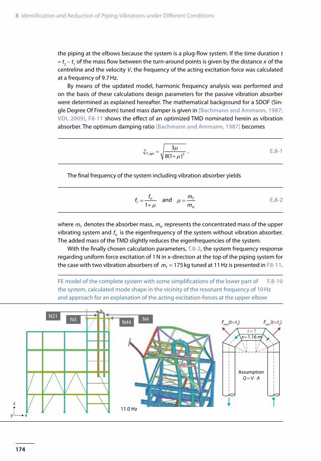
Furthermore, understanding the resonance excitation was of interest. Load simula-tions were created to describe the mass flow excitation. F.8-10 also explains an approach for possible excitation-forces acting at the upper elbow: Impact deviation forces act on
174
8 Identification and Reduction of Piping-Vibrations under Different Conditions
N4N21
z
N3 N44
y x
x=1.16 mt = ?
AssumptionQ = V ⋅ A
Fres2(t=t2) Fres1(t=t2)
11.0 Hz
FE model of the complete system with some simplifications of the lower part of the system, calculated mode shape in the vicinity of the resonant frequency of 10 Hz and approach for an explanation of the acting excitation-forces at the upper elbow
F.8-10
the piping at the elbows because the system is a plug-flow system. If the time duration t = t2 − t1 of the mass flow between the turn-around points is given by the distance x of the centreline and the velocity V, the frequency of the acting excitation force was calculated at a frequency of 9.7 Hz.
By means of the updated model, harmonic frequency analysis was performed and on the basis of these calculations design parameters for the passive vibration absorber were determined as explained hereafter. The mathematical background for a SDOF (Sin-gle Degree Of Freedom) tuned mass damper is given in [Bachmann and Ammann, 1987; VDI, 2009]. F8-11 shows the effect of an optimized TMD nominated herein as vibration absorber. The optimum damping ratio [Bachmann and Ammann, 1987] becomes
, 3
38(1 )T opt
µξµ
=+
. E.8-1
The final frequency of the system including vibration absorber yields
1
HT
ff
µ=
+ and T
H
mm
µ = E.8-2
where Tm denotes the absorber mass, Hm represents the concentrated mass of the upper vibrating system and Hf is the eigenfrequency of the system without vibration absorber. The added mass of the TMD slightly reduces the eigenfrequencies of the system.
With the finally chosen calculation parameters, T.8-2, the system frequency response regarding uniform force excitation of 1 N in x-direction at the top of the piping system for the case with two vibration absorbers of Tm = 175 kg tuned at 11 Hz is presented in F8-11.
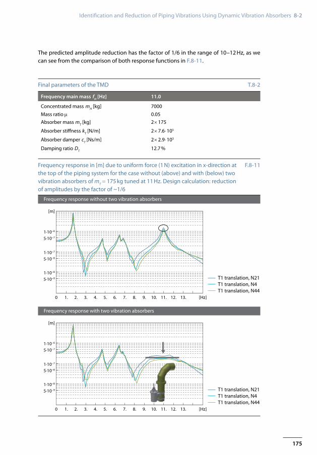
175
Identification and Reduction of Piping Vibrations Using Dynamic Vibration Absorbers 8-2
Frequency response without two vibration absorbers
Frequency response with two vibration absorbers
0 2. 3.1. 6. 7.4. 5. 9. 10.8. 11. 12. 13. [Hz]
[m]
5·10−9
1·10−8
1·10−7
5·10−8
1·10−6
5·10−7
T1 translation, N21T1 translation, N4T1 translation, N44
0 2. 3.1. 6. 7.4. 5. 9. 10.8. 11. 12. 13. [Hz]
[m]
5·10−9
1·10−8
1·10−7
5·10−8
1·10−6
5·10−7
T1 translation, N21T1 translation, N4T1 translation, N44
Frequency main mass fH [Hz] 11.0
Concentrated mass mH [kg] 7000Mass ratio µ 0.05Absorber mass mT [kg] 2 × 175
Absorber stiffness kT [N//m] 2 × 7.6 ⋅105
Absorber damper cT [Ns//m] 2 × 2.9 ⋅103
Damping ratio DT 12.7 %
Frequency response in [m] due to uniform force (1 N) excitation in x-direction at the top of the piping system for the case without (above) and with (below) two vibration absorbers of mT = 175 kg tuned at 11 Hz. Design calculation: reduction of amplitudes by the factor of ~1//6
F.8-11
Final parameters of the TMD T.8-2
The predicted amplitude reduction has the factor of 1//6 in the range of 10–12 Hz, as we can see from the comparison of both response functions in F.8-11.
176
8 Identification and Reduction of Piping-Vibrations under Different Conditions
8-2-4 Final Design of Passive Vibration Absorbers for the Investigated Piping System
Piping systems are complex three-dimensional structures usually with many and com-plicated mode shapes. The design of a dynamic vibration absorber has to consider the specific requirements of the piping systems in question and should enable easy and safe installation. The optimal mounting location in regard to vibration reduction is not always available. Therefore the dynamic absorber should work in many positions. The selected design works analogously to the mock-up test with a defined mass that is connected to a member. The bending eigenfrequency depends on the stiffness of the member which in turn depends on the free and vibrating length. For tuning purposes this length is adjust-able, see F.8-5.
For energy dissipation the vibrating mass of the dynamic absorber moves in a highly viscous fluid. The absorber can be attached to the pipe in every position and the direction of the absorber vibration adapts itself to the motion of the pipe. Vibrating mass, stiffness and damping were chosen in accordance to known optimization criteria for harmonic and random vibrations.
Based on measurements and finite element calculations the modal or resonant mass of the structure was determined. With a mass ratio of 5 % the total vibrating mass of the absorber was 350 kg. The optimal damping ratio of the absorber is about 11 %. In the dis-cussed case two absorbers with half the required vibrating mass were designed to mini-mize the additional weight attached to one point of the pipe.
8-3 Investigation of Local Wall Thinning on Piping Vibrations
The system response of a piping system which is excited by vibrations depends on the magnitude of the excitation, its frequency spectrum, and the structural-dynamic charac-teristics of the whole piping. The structural-dynamic characteristics of such a system can change over time due to ageing and damage mechanisms. An important damage mecha-nism in facilities worldwide is local wall thinning (LWT) due to erosion-corrosion, which can lead to sudden failures such as bursting, break, or collapse as well as fatigue [Dooley and Chexal, 2000; Michel et al., 2001; NISA, 2005; Tinga and Ma, 1999]. Local wall thin-ning reduces burst pressure, failure load, deformation capacity and the lifetime of elbows [Ahn et al., 2002; Kim et al., 2003]. Knowing the deformation and damage mechanism behaviour of these components is important to predict the dynamical behaviour of the system and its ability to resist operation related vibrations and earthquakes. Although plastic limit load, burst pressure, fatigue due to bending and fracture behaviour of elbows and straight pipes with local wall thinning have been a focus of recent investigations [Hasegawa et al., 2011; Kim et al, 2008, 2009a, 2009b; Kim and Park, 2008, 2003; Oh et al., 2007; Oyamada et al., 2012; Takahashi et al., 2009, 2010], only few investigations exist on the change of the dynamical behaviour of piping under seismic loading due to

177
Investigation of Local Wall Thinning on Piping Vibrations 8-3
local wall thinning in elbows [Namita et al., 2003; Nakamura et al., 2010; Schmidt et al., 1991]. No structural dynamic investigations could be found of systems dealing with a small diameter branch, containing elbows with local wall thinning, which are attached to larger diameter piping. Therefore it is important to investigate the implications of local wall thinning on the integrity and the dynamical characteristics of piping and to develop procedures to predict related safety margins.
Within WP2 experiments are conducted at MPA Stuttgart to measure and predict the changes of the structural-dynamic characteristics of piping due to local wall thinning. Low cycle fatigue tests under seismic loading and numerical studies are performed to inves-tigate influences of local wall thinning on the integrity of the system. Material investiga-tions and system identification as well as model-updating are performed.
8-3-1 Investigated System and Design Studies
The objective of the design studies was to find a geometry, which adds a small di-ameter branch, containing an elbow with local wall thinning, to the mock-up, to create a piping system, which fulfills the following criteria:
//// The system’s first natural mode shape in vertical direction should have maximum von Mises stress concentrated in the elbow with local wall thinning. The stress in all other parts of the piping should be significantly lower.
//// The natural frequency, belonging to this mode shape, should be as low as to be excited by a common earthquake-acceleration-input.
//// Flanges should be added to the branch, to allow simple replacement of damaged elbows.
//// Ovalization of the damaged elbow should be possible and not constrained by adjacent flanges.
The small diameter branch is made of structural grade carbon steel (material no. 1.0308), which is a commonly used material for elbows in power plants, affected by local wall thinning.
The material characteristics of 1.0308 were determined with tensile tests at room temperature with test specimens from different positions of the elbow. As expected, the bending procedure of the elbow led to different stress-strain curves at different positions of the elbow (see F.8-12).
An exemplary comparison of two investigated design geometries is shown below and the reasons which lead to the chosen geometry are explained. To study the eigen-modes and eigenfrequencies of various investigated geometries, an FE model consist-ing of 30211 C3D8R elements was created. Straight pipes were added to the elbow with local-wall thinning, to allow undisturbed ovalization. Flanges were added to the straight pipes to allow simple exchange of damaged elbows. The branch is added vertically to the mock-up. Different locations for the attached branch were compared (Position 1: close to mock-up elbow, position 2: close to free end). F.8-13 shows a comparison of the first eigenfrequencies and mode shapes of two systems with different branch attachment po-sitions. Both supports of the mock-up (at the end of the small diameter branch and at the vertical end of the mock-up) are clamped.

178
8 Identification and Reduction of Piping-Vibrations under Different Conditions
0 10 20 30 40 50Strain [%]
Stre
ss [M
Pa]
600
0
500
Intrados (axial direction)Intrados (circumferential direction)Extrados (axial direction)
Crown (axial direction)Crown (circumferential direction)Straight pipe (circumferential direction)Straight pipe (axial direction)
100
200
300
400
Material Young's Modulus [MPa] Density [kg/m³] Poisson’s ratio Yield strength [MPa]
1.5415 212600 7850 0.28 2751.0460 210 000 7850 0.28 2401.0308 207000 7850 0.28 see stress
Material characteristics (above) and Stress-Strain curves (below) at different positions of the elbow made of material with no. 1.0308
F.8-12
A comparison of the different geometries yielded the following results: Depending on the position of the branch, the static boundary conditions, and the length of the straight pipes in the branch, the locations of peak von Mises stress and the eigenfrequencies change. Compared with the out-of-plane mode shapes, the in-plane mode shapes yielded better concentration of stress in the elbow of the branch. F.8-14 shows the first vertical mode shape with maximum von Mises stress in the connecting weld between the branch and the large piping. An attachment of the branch in position 1 reduced the stress in the weld between the branch and the large piping.
Utilizing the results of the design studies it was possible to select a final geometry (compare F.8-17), reducing stresses in the welds and increasing stresses in the elbow. By using a hinge as support for the branch (allowing free rotation around the y- and z-axis) a system with a first vertical eigenfrequency of 4.8 Hz, with low stress in the weld between the branch and the large diameter piping and high stress in the locally wall thinned elbow was created.
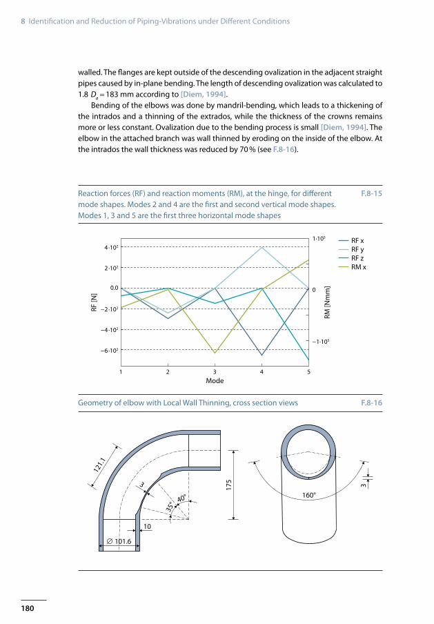
F.8-15 shows the reaction forces (RF) and the reaction moments (RM) around the x-ax-is, at the hinge, for the first five eigenmodes of the piping. Modes 1, 3 and 5 are horizontal. Modes 2 and 4 are vertical. Mode 2 reduces stress in the weld between the branch and the large diameter piping, while mode 4 increases the stress in the weld.
This hinge and the fixed support at the bottom of the large diameter piping are the only supports of the system. The straight pipes and the elbow in the branch have an outer diameter of Da = 101.6 mm and a wall thickness of tb = 10 mm. The elbow has a bending radius of R = 175 mm. With a diameter ratio of u = 1.245, the elbow is considered thick-

179
Investigation of Local Wall Thinning on Piping Vibrations 8-3
Mode 2 Mode 3Mode 1
3.18 Hz(out-of-plane)
5.77 Hz(in-plane)
7.93 Hz(out-of-plane)
Mode 2 Mode 3Mode 1
5.52 Hz(out-of-plane)
6.57 Hz(out-of-plane)
10.37 Hz(in-plane)
z
max 1.454e+01
+1.454e+01+1.333e+01+1.212e+01+1.091e+01+9.697e+00+8.486e+00+7.276e+00+6.065e+00+4.855e+00+3.644e+00+2.434e+00+1.223e+00+1.263e−02
S, Mises (avg: 75%)
+5.201e+00+4.768e+00+4.334e+00+3.901e+00+3.468e+00+3.034e+00+2.601e+00+2.167e+00+1.734e+00+1.301e+00+8.672e−01+4.338e−01+3,800e−04
S, Mises (avg: 75%)
Step: EigFreq, Get eigenfrequenciesMode 2: Value = 913.22, Freq = 4.8096 (cycle/time)Primary Var: S, MisesDeformed Var: U Deformation scale factor: +8.900e+02
x
yStep: EigFreq, Get eigenfrequenciesMode 2: Value = 1705.5, Freq = 6.5727 (cycle/time)Primary Var: S, Misesz x
y
Eigenmodes of geometric variations of the mock-up, above: branch position 1 with a hinge support at the branch, below: branch position 2 with a fixed sup-ported branch
F.8-13
First vertical eigenmode (position 2, without hinge) with maximum stress in the connecting weld between the small and the large diameter piping (left), first vertical eigenmode (position 1, with hinge) with maximum stress in the elbow of the branch (right)
F.8-14
180
8 Identification and Reduction of Piping-Vibrations under Different Conditions
1 2 3 4 5Mode
RF [N
]
RM [N
mm
]
1·105
−1·105
0
4·102
2 ·102
−4·102
−6·102
−2·102
RF xRF yRF zRM x
0.0
∅ 101.6
10
35° 40° 160°
1753
121.
1
3
Reaction forces (RF) and reaction moments (RM), at the hinge, for different mode shapes. Modes 2 and 4 are the first and second vertical mode shapes. Modes 1, 3 and 5 are the first three horizontal mode shapes
F.8-15
Geometry of elbow with Local Wall Thinning, cross section views F.8-16
walled. The flanges are kept outside of the descending ovalization in the adjacent straight pipes caused by in-plane bending. The length of descending ovalization was calculated to 1.8 Da = 183 mm according to [Diem, 1994].
Bending of the elbows was done by mandril-bending, which leads to a thickening of the intrados and a thinning of the extrados, while the thickness of the crowns remains more or less constant. Ovalization due to the bending process is small [Diem, 1994]. The elbow in the attached branch was wall thinned by eroding on the inside of the elbow. At the intrados the wall thickness was reduced by 70 % (see F.8-16).

181
Investigation of Local Wall Thinning on Piping Vibrations 8-3
z x
y
MP2 MP3 MP4
MP5
MP6MP8 MP9 MP10
MP11, shaker
Elbow with localwall thinning
MP12, strain
MP13, strain
MP7, shaker
MP1
FE model of the investigated system and the added branch and measurement positions
F.8-17
8-3-2 System Identification and Model-Updating
In the following discussion, first the final model of the chosen system with local wall thinning in the elbow and afterwards another model without wall thinning will be de-scribed. In order to keep time analysis studies within reasonable bounds, the number of elements was kept as low as possible, yet considered adequate. The large diameter piping is modelled with 24 S8R shell elements in circumferential direction – altogether 4892 ele-ments, using Simpson’s thickness integration rule and five thickness integration points. The small diameter branch is modeled with C3D20 solid elements, two over the thickness and 48 in circumferential direction – altogether 5160 elements. This model was chosen as final because further mesh refinement studies showed changes in eigenfrequencies smaller than 0.008 % when increasing the amount of solid elements across the wall thick-ness from 2 to 3.
The two different element regions are connected with a surface-to-surface tie con-straint. The thickness of the shell elements is adjusted according to wall thickness meas-urements. For the straight pipes modelled with shell elements, a wall thickness of tsp = 17.7 mm is used. For the wall thickness of the elbows near MP2, MP4 and MP7 in F.8-17, wall thicknesses of teb1 = 17.3 mm, teb2 = 17.4 mm and teb3 = 17.5 mm are used. The shaker has a mass of m = 72.4 kg and is adjusted to be able to excite the system in the vertical direction. It was used in two positions, see F.8-17. The shaker is modelled as a mass point in the centre of the pipe taking into account the rotatory mass moment of inertia. As the two supports are not perfectively stiff, they are modelled with translational and rotational springs. For determining these parameters model-updating was carried out using Output Only Modal Analysis (OOMA).
OOMA was performed during all experimental studies. The system with local wall thin-ning, shown in F.8-17, was investigated with impact-tests and snap-backs. Additionally strain gauges were applied to the branch.
The identified natural frequencies and mode shapes were used for model-updating of the FE model. Modal analysis was carried out for the system with the shaker position at MP11. Using FEM tools for sensitivity studies and model-updating brought about a strong

182
8 Identification and Reduction of Piping-Vibrations under Different Conditions
Position DOF Start value [Nmm/rad] End value [Nmm/rad]
Branch HX 4.5⋅1012 4.11⋅1012
Large diameter piping HX 4.5⋅1012 6.16⋅1010
HY 4.5⋅1012 9.48⋅1013
HZ 4.5⋅1012 5.18⋅1010
No. of mode Experiment [Hz] FEM [Hz] Error [%] MAC [%]
1 1.96 1.97 0.51 99.6
2 3.76 3.77 0.27 96.13 7.21 7.29 1.11 994 9.48 9.40 –0.84 97.35 13.10 13.21 0.84 996 14.33 14.15 –1.26 987 24.68 24.44 –0.97 95.48 26.40 26.12 –1.06 95.69 46.62 46.58 –0.09 92.3
10 46.88 47.55 1.43 95.2
Comparison: measurement – updated calculation
Rotational spring stiffness before and after updating (HX, HY, HZ, rotation around x-, y-, z-axis)
T.8-4
T.8-3
influence of the rotational spring stiffness on the eigenfrequencies. The starting value for model-updating, a spring stiffness of kstart = 4.5⋅1012 Nmm//rad, was selected for all springs. By adjusting the spring stiffnesses in this way (see T.8-3), the average error of the first 10 eigenfrequencies could be reduced from 3.7 % to 1.1 %.
Including the influence of the load case dead load and performing non-linear geom-etry analysis, the eigenfrequencies of the system are reduced. The average error decreases from 1.1 % to 0.84 %. T.8-4 shows the comparison of the final, updated model with the measured natural frequencies and mode shapes.
The first six modes of the updated FE model of the system with the attached branch containing local wall thinning are shown in F.8-19 and can be compared with the modes of the former system given in F.8-4 and with the design studies, without hinge and shaker-mass, before construction of the system and model updating shown in F.8-13.
Damping ratio was determined for the different modes by means of impact tests (see F.8-18). In the case of rotation around the y-axis (see mode 1 and mode 5 in F.8-19) damp-ing is significantly higher compared to the other modes. This may be caused by friction in the hinge.
After model-updating of the FE model with local wall thinning, described above, the second model was created by replacing the wall thinned elbow with an elbow without wall thinning. The amount of elements in the system does not change. The elements stay in the same position. Only the size of the elements changed, which had no influence on the mesh quality. For system identification, acceleration measurements were carried out at 13 different positions in three directions (MP1 to MP13).
The FE model without local wall thinning, shows the position of maximum von Mises stress at the connection between the branch and the large diameter piping for modes 1,

183
Investigation of Local Wall Thinning on Piping Vibrations 8-3
1 2 3 4 5 6 7 8 9 10Mode
Dam
ping
[%]
2.5
2.0
1.0
0.5
0.0
1.5
Mode 2 Mode 3Mode 1
1.97 Hz(out-of-plane)
3.77 Hz(in-plane)
7.29 Hz(out-of-plane)
Mode 5 Mode 6Mode 4
9.40 Hz(in-plane)
13.21 Hz(out-of-plane)
14.15 Hz(in-plane)
Damping ratio determined from acceleration measurements during impact-tests
First 6 modes of the updated FE model of the piping with local wall thinning
F.8-18
F.8-19
3, 4, 5 and 6, while mode 2 has maximum von Mises stress at the crown of the elbow. In comparison to this, the system with wall thinning shows the position of maximum von Mises stress at the intrados of the wall thinned elbow for modes 1, 2 and 3. Modes 4, 5 and 6 have maximum von Mises stress at the connection weld between the branch and the large diameter piping. Because of the reduction of the wall thickness, the location of maximum bending and failure during excitation of the first vertical mode moves from the crown of the elbow to the intrados, which is in agreement with [Takahashi et al., 2009].
184
8 Identification and Reduction of Piping-Vibrations under Different Conditions
50 10 15 20 25 30Frequency [Hz]
Acce
lera
tion
[m/s
2]
10
6
4
2
0
8
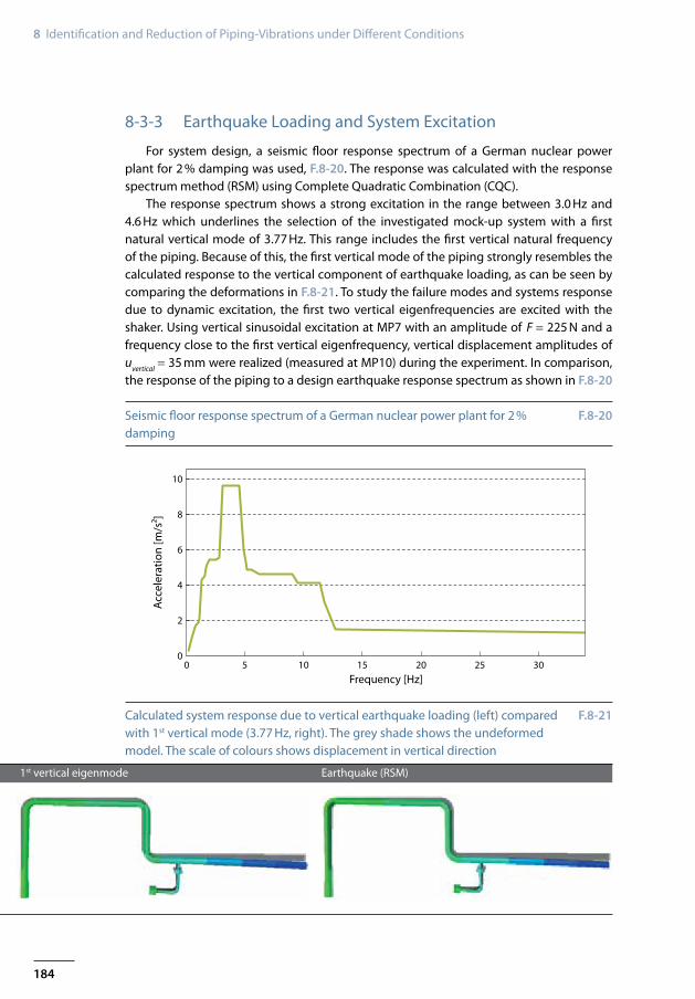
Earthquake (RSM)1st vertical eigenmode
Calculated system response due to vertical earthquake loading (left) compared with 1st vertical mode (3.77 Hz, right). The grey shade shows the undeformed model. The scale of colours shows displacement in vertical direction
Seismic floor response spectrum of a German nuclear power plant for 2 % damping
F.8-21
F.8-20
8-3-3 Earthquake Loading and System Excitation
For system design, a seismic floor response spectrum of a German nuclear power plant for 2 % damping was used, F.8-20. The response was calculated with the response spectrum method (RSM) using Complete Quadratic Combination (CQC).
The response spectrum shows a strong excitation in the range between 3.0 Hz and 4.6 Hz which underlines the selection of the investigated mock-up system with a first natural vertical mode of 3.77 Hz. This range includes the first vertical natural frequency of the piping. Because of this, the first vertical mode of the piping strongly resembles the calculated response to the vertical component of earthquake loading, as can be seen by comparing the deformations in F.8-21. To study the failure modes and systems response due to dynamic excitation, the first two vertical eigenfrequencies are excited with the shaker. Using vertical sinusoidal excitation at MP7 with an amplitude of F = 225 N and a frequency close to the first vertical eigenfrequency, vertical displacement amplitudes of uvertical = 35 mm were realized (measured at MP10) during the experiment. In comparison, the response of the piping to a design earthquake response spectrum as shown in F.8-20
185
Investigation of Local Wall Thinning on Piping Vibrations 8-3
0 200 400 600 800 1600 2000180012001000 1400
Time [s]
MP:8:+y
rpm
MP:
8:+y
[g]
Revo
lutio
ns p
er m
inut
e [r
pm]
4
2
3200
150
100
0
50
250
0
1
−2
−3
−1
−4
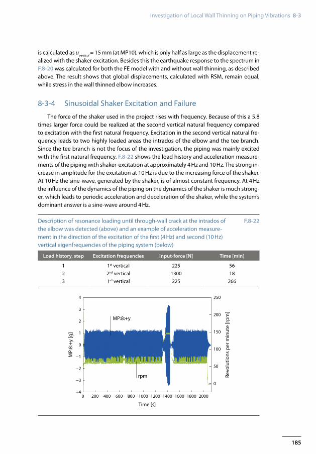
Load history, step Excitation frequencies Input-force [N] Time [min]
1 1st vertical 225 562 2nd vertical 1300 183 1rd vertical 225 266
Description of resonance loading until through-wall crack at the intrados of the elbow was detected (above) and an example of acceleration measure-ment in the direction of the excitation of the first (4 Hz) and second (10 Hz) vertical eigenfrequencies of the piping system (below)
F.8-22
is calculated as uvertical = 15 mm (at MP10), which is only half as large as the displacement re-alized with the shaker excitation. Besides this the earthquake response to the spectrum in F.8-20 was calculated for both the FE model with and without wall thinning, as described above. The result shows that global displacements, calculated with RSM, remain equal, while stress in the wall thinned elbow increases.
8-3-4 Sinusoidal Shaker Excitation and Failure
The force of the shaker used in the project rises with frequency. Because of this a 5.8 times larger force could be realized at the second vertical natural frequency compared to excitation with the first natural frequency. Excitation in the second vertical natural fre-quency leads to two highly loaded areas the intrados of the elbow and the tee branch. Since the tee branch is not the focus of the investigation, the piping was mainly excited with the first natural frequency. F.8-22 shows the load history and acceleration measure-ments of the piping with shaker-excitation at approximately 4 Hz and 10 Hz. The strong in-crease in amplitude for the excitation at 10 Hz is due to the increasing force of the shaker. At 10 Hz the sine-wave, generated by the shaker, is of almost constant frequency. At 4 Hz the influence of the dynamics of the piping on the dynamics of the shaker is much strong-er, which leads to periodic acceleration and deceleration of the shaker, while the system’s dominant answer is a sine-wave around 4 Hz.
186
8 Identification and Reduction of Piping-Vibrations under Different Conditions
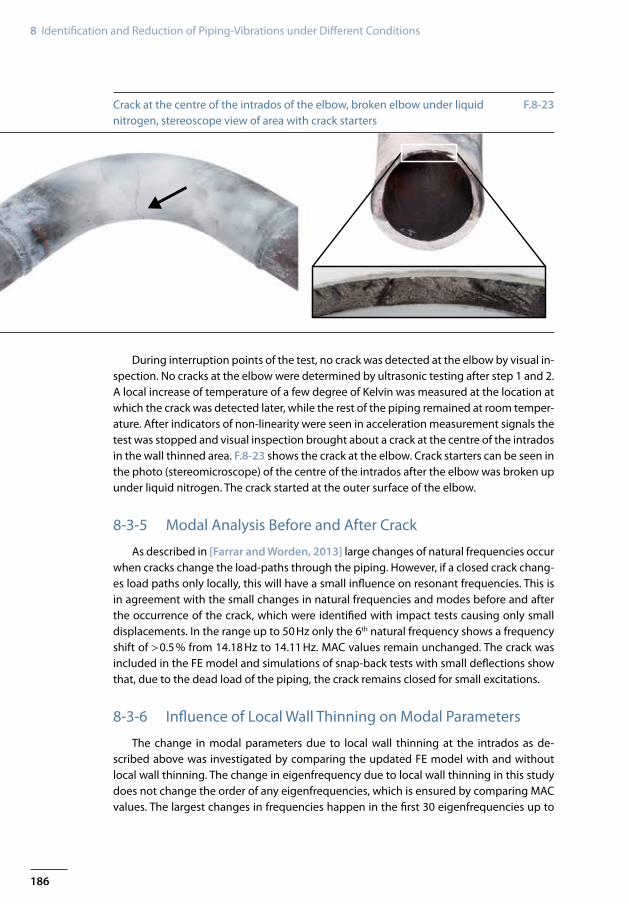
Crack at the centre of the intrados of the elbow, broken elbow under liquid nitrogen, stereoscope view of area with crack starters
F.8-23
During interruption points of the test, no crack was detected at the elbow by visual in-spection. No cracks at the elbow were determined by ultrasonic testing after step 1 and 2. A local increase of temperature of a few degree of Kelvin was measured at the location at which the crack was detected later, while the rest of the piping remained at room temper-ature. After indicators of non-linearity were seen in acceleration measurement signals the test was stopped and visual inspection brought about a crack at the centre of the intrados in the wall thinned area. F.8-23 shows the crack at the elbow. Crack starters can be seen in the photo (stereomicroscope) of the centre of the intrados after the elbow was broken up under liquid nitrogen. The crack started at the outer surface of the elbow.
8-3-5 Modal Analysis Before and After Crack
As described in [Farrar and Worden, 2013] large changes of natural frequencies occur when cracks change the load-paths through the piping. However, if a closed crack chang-es load paths only locally, this will have a small influence on resonant frequencies. This is in agreement with the small changes in natural frequencies and modes before and after the occurrence of the crack, which were identified with impact tests causing only small displacements. In the range up to 50 Hz only the 6th natural frequency shows a frequency shift of > 0.5 % from 14.18 Hz to 14.11 Hz. MAC values remain unchanged. The crack was included in the FE model and simulations of snap-back tests with small deflections show that, due to the dead load of the piping, the crack remains closed for small excitations.
8-3-6 Influence of Local Wall Thinning on Modal Parameters
The change in modal parameters due to local wall thinning at the intrados as de-scribed above was investigated by comparing the updated FE model with and without local wall thinning. The change in eigenfrequency due to local wall thinning in this study does not change the order of any eigenfrequencies, which is ensured by comparing MAC values. The largest changes in frequencies happen in the first 30 eigenfrequencies up to
187
System Identification of Piping System in a Lignite Power Plant 8-4
61 11 16 21 26
Mode
MAC
[%]
100.00
99.85
99.80
99.75
99.70
99.95
99.90
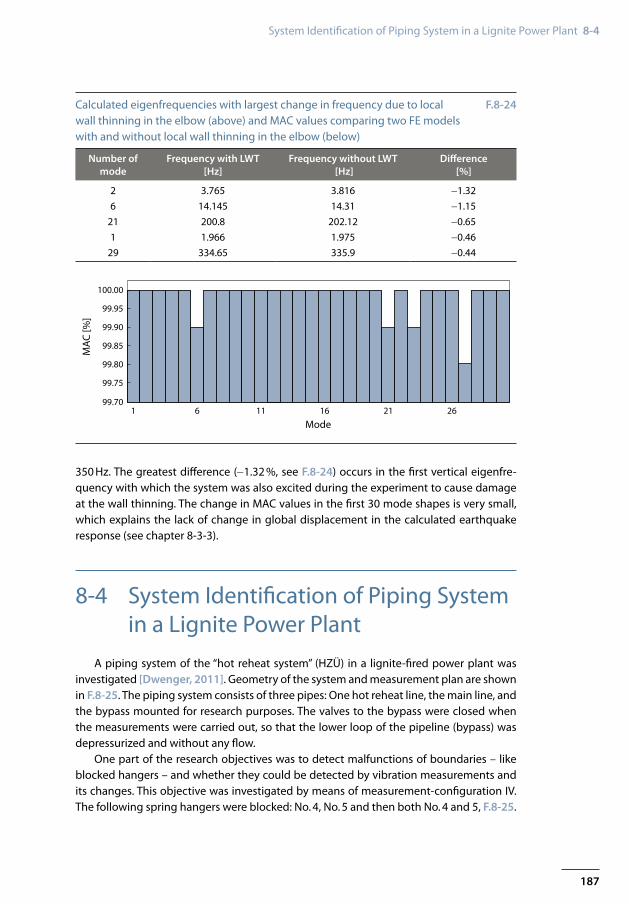
Number of mode
Frequency with LWT [Hz]
Frequency without LWT [Hz]
Difference [%]
2 3.765 3.816 −1.326 14.145 14.31 −1.15
21 200.8 202.12 −0.651 1.966 1.975 −0.46
29 334.65 335.9 −0.44
Calculated eigenfrequencies with largest change in frequency due to local wall thinning in the elbow (above) and MAC values comparing two FE models with and without local wall thinning in the elbow (below)
F.8-24
350 Hz. The greatest difference (−1.32 %, see F.8-24) occurs in the first vertical eigenfre-quency with which the system was also excited during the experiment to cause damage at the wall thinning. The change in MAC values in the first 30 mode shapes is very small, which explains the lack of change in global displacement in the calculated earthquake response (see chapter 8-3-3).
8-4 System Identification of Piping System in a Lignite Power Plant
A piping system of the “hot reheat system” (HZÜ) in a lignite-fired power plant was investigated [Dwenger, 2011]. Geometry of the system and measurement plan are shown in F.8-25. The piping system consists of three pipes: One hot reheat line, the main line, and the bypass mounted for research purposes. The valves to the bypass were closed when the measurements were carried out, so that the lower loop of the pipeline (bypass) was depressurized and without any flow.
One part of the research objectives was to detect malfunctions of boundaries – like blocked hangers – and whether they could be detected by vibration measurements and its changes. This objective was investigated by means of measurement-configuration IV. The following spring hangers were blocked: No. 4, No. 5 and then both No. 4 and 5, F.8-25.

188
8 Identification and Reduction of Piping-Vibrations under Different Conditions
MP3 x,y,z12
10
16
14
Y,Z
Measurement points (MP) 1−9,11,13 and 15 are located on the insulation of the piping. Measurement points 10 and 14 are fixed to clamps magnetically. MP16 is located at the T-girder which supports a hanger. MP12 is mounted on a cross girder supporting the vessel. Measurement points 23-25 are only vertical measuement points at the bypass.
Conf. MP x; y; z MP z
I
II
III
IV
V
1, 2, 3,10, 111, 4, 5, 12, 131, 6, 7, 14, 151, 8, 9, 14, 161, 8, 9, 16
23, 24, 25
MP6 x,y,z 5
4MP8 x,y,zMP9 x,y,z
MP7 x,y,z
MP5 x,y,z
MP1 x,y,zreference
MP2 x,y,z
MP11 x,y,z
MP4 x,y,z
Geometry of piping system, measurement plan and blocked spring hangers F.8-25
The investigated piping system – with the exception of the bypass – is insulated over the entire length. The vibration measurements were carried out on the insulation, as the demounting of insulation is of great expenditure and not possible during operation. In-vestigations during former research projects [Kerkhof et. al., 2001] showed that up to a frequency of about 20 Hz vibration measurements on insulation can be carried out reli-ably. Therefore, a limited number of eigenfrequencies and corresponding mode shapes are investigated and evaluated in the following. In case of the piping system examined, there are numerous restrictions regarding the accessibility of relevant points. For acces-sibility of the main line section above the bypass, a scaffold was set up. The scaffold was located half-height between the bypass and the mainline. Access to the section of the main line above the bypass was only possible via scaffold. The other main line sections were accessible only to a limited extent.
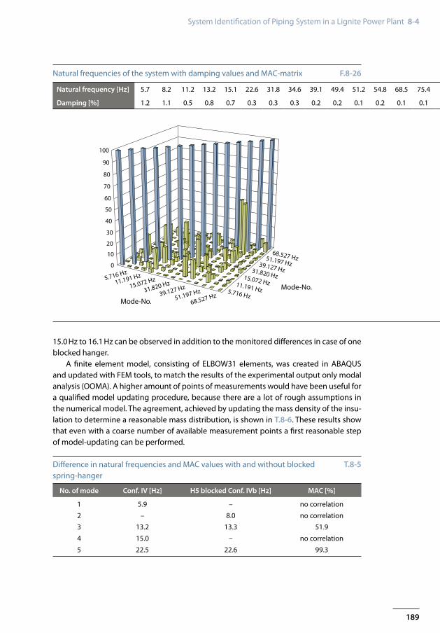
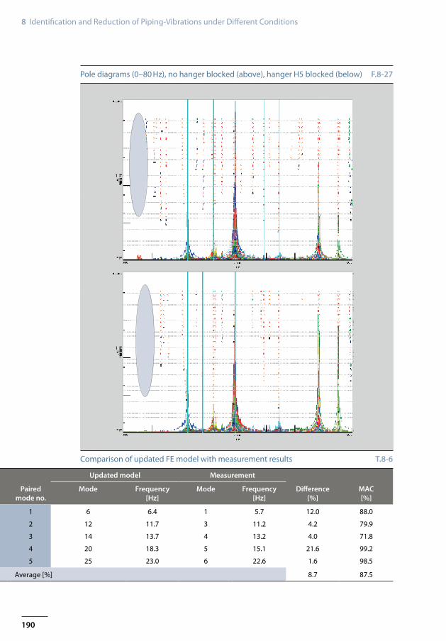
The evaluation of the acceleration measurements was carried out with LMS Test.Lab and the application OMA “Operational Modal Analysis” was used. For the calculation of the stable poles all cross power spectra of the respective measurement-configurations were selected and the LMS Test.Lab add-in “Operational Polymax” was used. Stable poles were calculated in the range from 0 to 80 Hz, see F.8-26.
During the evaluation of modal analysis results of systems with blocked hangers and systems with operating (unblocked) hangers not only the frequency shift, but also the characteristics of pole stabilization diagrams and the correlations were investigated. The differences in case of blocked hanger H5 are visible in the pole diagrams, in the correlation and in the frequency shift, see F.8-27 and T.8-5. The natural frequency of 5.9 Hz disap-pears, a natural frequency of 8.0 Hz appears within the low frequency domain.
At 13.2 Hz a bad correlation is given between the modes of the corresponding natural frequencies. In the case of two blocked hangers a natural frequency-shift of 1.1 Hz from
189
System Identification of Piping System in a Lignite Power Plant 8-4
100
90
80
70
60
50
40
Mode-No.
Mode-No.
30
20
10
0
5.716 Hz
11.191 Hz
15.072 Hz
31.820 Hz
39.127 Hz
51.197 Hz
68.527 Hz
68.527 Hz51.197 Hz39.127 Hz31.820 Hz15.072 Hz11.191 Hz5.716 Hz
Natural frequency [Hz] 5.7 8.2 11.2 13.2 15.1 22.6 31.8 34.6 39.1 49.4 51.2 54.8 68.5 75.4
Damping [%] 1.2 1.1 0.5 0.8 0.7 0.3 0.3 0.3 0.2 0.2 0.1 0.2 0.1 0.1
No. of mode Conf. IV [Hz] H5 blocked Conf. IVb [Hz] MAC [%]
1 5.9 – no correlation
2 – 8.0 no correlation
3 13.2 13.3 51.9
4 15.0 – no correlation
5 22.5 22.6 99.3
Natural frequencies of the system with damping values and MAC-matrix F.8-26
Difference in natural frequencies and MAC values with and without blocked spring-hanger
T.8-5
15.0 Hz to 16.1 Hz can be observed in addition to the monitored differences in case of one blocked hanger.
A finite element model, consisting of ELBOW31 elements, was created in ABAQUS and updated with FEM tools, to match the results of the experimental output only modal analysis (OOMA). A higher amount of points of measurements would have been useful for a qualified model updating procedure, because there are a lot of rough assumptions in the numerical model. The agreement, achieved by updating the mass density of the insu-lation to determine a reasonable mass distribution, is shown in T.8-6. These results show that even with a coarse number of available measurement points a first reasonable step of model-updating can be performed.
190
8 Identification and Reduction of Piping-Vibrations under Different Conditions
Updated model Measurement
Paired mode no.
Mode Frequency [Hz]
Mode Frequency [Hz]
Difference [%]
MAC [%]
1 6 6.4 1 5.7 12.0 88.0
2 12 11.7 3 11.2 4.2 79.9
3 14 13.7 4 13.2 4.0 71.8
4 20 18.3 5 15.1 21.6 99.2
5 25 23.0 6 22.6 1.6 98.5
Average [%] 8.7 87.5
Comparison of updated FE model with measurement results T.8-6
Pole diagrams (0–80 Hz), no hanger blocked (above), hanger H5 blocked (below) F.8-27

191
Conclusion 8-5
8-5 ConclusionSafe operation, availability and lifetime assessment of piping are of utmost concern
for chemical plants. The investigated piping reactor is supported by a tall structure fixed at the base. As a result, the steel building stiffness decreases with height. Furthermore large piping-elbow forces act at the top of the building, which leads to large vibration ampli-tudes in the vicinity of 10 Hz where coupled piping-building resonance excitations occur due to plugs running through the line. Since both piping system and supporting structure exhibited these large vibration amplitudes, dampers or shock absorbers placed between them would prove less effective.
Therefore, a special vibration absorber was developed for such piping systems. This special vibration absorber for piping consists of a cantilever beam with a concentrated mass at the end, vibrating in a cylinder. The vibrations are damped by a special fluid within the cylinder. The bending eigenfrequency of the cantilever beam depends on the stiffness of the member which in turn depends on the free and vibrating length L of the TMD. For tuning purposes this length is adjustable. The absorber can be attached to the pipe in various positions and the direction of the absorber vibration adapts itself to the motion of the pipe. A prototype of this vibration absorber was tested at the laboratory of MPA Stutt-gart with success. Root cause analysis of the large vibrations at the piping reactor such as thorough measurement campaigns and detailed FE models updated by operational modal analysis data brought about a system-identification and an understanding of the resonance effect. On this basis a reasonable design for two vibration absorbers connected to the piping in the upper part of the structure was found.
The load bearing behaviour of a laboratory piping system with a branch containing an elbow with local wall thinning (thickness reduced by 70 % at the intrados) was investigat-ed. System identification by means of experimental modal analysis and model-updating is still a challenge, if one of the objectives is to detect local flaws. Model-updating of the FE model by adjusting support stiffness led to very good agreement between measured and calculated modal characteristics. Due to local wall thinning, the location of damage changed from crown to intrados. Numerical investigation of the influence of the local wall thinning at the intrados on the modal characteristics showed small changes in eigenfre-quencies (largest change is 1.3 % at the first vertical eigenfrequency), while the change in mode shapes was very small except for a few modes of higher order. Afterwards the system was subjected to a simulation of in-plane bending caused by earthquake loading to test the safety margin of the system with the wall thinned elbow. No damage occurred in the wall thinned elbow of the branch. Subsequently sinusoidal shaker excitation was carried out in the natural frequency of the first vertical mode leading to a fatigue crack at the pre-calculated position (circumferential, in the wall thinned area of the intrados).
For piping in conventional power plants it is very difficult to achieve a good agree-ment between numerical and experimental modal analysis, because of the model size, difficult boundary conditions, and non-linearities like stick-slip effects due to friction. Am-plitude dependent vibration behaviour might be present. Reasonable model-updating results could be achieved regarding the mass distribution in respect to the density of the insulation even with a coarse number of available measurement points. System changes

192
8 Identification and Reduction of Piping-Vibrations under Different Conditions
due to one blocked hanger could be reflected in different pole stabilization-diagrams of OOMA, in the correlations by means of the MAC values and in one case in a clear frequen-cy shift (blocking of two hangers).
Acknowledgements
This work was performed with support from the EU (European Union) in the frame-work of the Large Collaborative Research Project IRIS (Integrated European Industrial Risk Reduction System, CP-IP 213968-2) in work package WP2.
ReferencesAhn, S.-H., Nam, K.-W., Yoo, Y.-S., Ando, K., Ji, S.-H., Ishiwata, M. and Hasegawa, K., 2002.
Fracture Behavior of Straight Pipe and Elbow with Local Wall Thinning. Nuclear Engineer-ing and Design 211.
Bachmann, H. and Ammann, W., 1987. Schwingungsprobleme bei Bauwerken – durch Men-schen und Maschinen induzierte Schwingungen. Series Structural Engineering Docu-ments 3d, 193 pp., International Association for Bridge and Structural Engineering (IABSE), Zurich, ISBN 3-8574-8051-3.
Barutzki, F., 2009. Reduzierung von Rohrleitungsschwingungen mittels Schwingungsdämp-fern. 24th FDBR-Fachtagung Rohrleitungstechnik on 24 and 25 March 2009, Magde-burg.
Diem, H., 1994. Untersuchung zum Geometrieeinfluss auf das Verformungs- und Versagens-verhalten von Rohrbogen. Techn.-Wiss. Ber. MPA Stuttgart.
Dooley, R. B. and Chexal, V. K., 2000. Flow-Accelerated Corrosion of Pressure Vessels in Fossil Plants. International Journal of Pressure Vessels and Piping 77.
Dwenger, F., 2011. Systemidentifikation und Zustandsanalyse einer Rohrleitung in einem Kohlekraftwerk auf der Basis gemessener Schwingungen. Studienarbeit, Institut für Ma-terialprüfung, Werkstuffkunde und Festigkeitslehre, Universität Stuttgart.
Farrar, C. R. and Worden, K., 2013. Structural Health Monitoring: A Machine Learning Per-spective. John Wiley & Sons, Ltd, Chichester.
Hasegawa, K., Meshii, T. and Scarth, D. A., 2011. Assessment of Piping Field Failures and Burst Tests on Carbon Steel Pipes With Local Wall Thinning Using ASME Section XI Code Case N-597-2. Journal of Pressure Vessel Technology 133(3).
Gurr-Beyer, C., Heiland, D., Jaquet, T. and Flöttmann, H., 2003. Vibration Maps – Qual-itätssicherung in schwingungsempfindlichen Produktionsstätten. VDI-Tagung „Baudyna-mik“ Kassel 2003, VDI-Bericht Nr. 1754.
Hinz, G. and Kerkhof, K., 2013. System Identification and Reduction of Vibrations of Piping in Different Conditions. ASME 2013 Pressure Vessels & Piping Division, K-PVP Conference, to be published.
IRIS, 2012. Large Collaborative Research Project IRIS (Integrated European Industrial Risk Reduction System, FP7-CP-IP 213968-2), European Union, 2008–2012.
Kerkhof, K. et al., 2001. Integrity of Safety-relevant Piping by means of Vibration Analysis. Phase II, German Reactor Safety Research - Project No. 150 1062.
193
References 8
Kim, J., Na, M. and Park, C.-Y., 2008. Effect of Local Wall Thinning on the Collapse Behavior of Pipe Elbows Subjected to a Combined Internal Pressure and In-Plane Bending Load. Nu-clear Engineering and Design 238:1275–1285.
Kim, J., Na, Y.-S. and Lee, S.-H., 2009b. Experimental Evaluation of the Bending Load Effect on the Failure Pressure of Wall-Thinned Elbows. Journal of Pressure Vessel Technology 131(3).
Kim, J., Weon and Park, C. Y., 2003. Criterion for Failure of Internally Wall Thinned Pipe un-der a Combined Pressure and Bending Moment. Transactions of the 17th International Conference on Structural Mechanics in Reactor Technology ( SMiRT 17) Prague, Czech Republic.
Kim, J. W., Lee, S. H. and Park, C.-Y, 2009a. Experimental Evaluation of the Effect of Lo-cal Wall Thinning on the Failure Pressure of Elbows. Nuclear Engineering and Design 239:2737–2746.
Kim, Y.-J., Kim, J., Ahn, J., Hong, S.-P. and Park, C.-Y., 2008. Effects of Local Wall Thinning on Plastic Limit Loads of Elbows using Geometrically Linear FE Limit Analyses. Engineering Fracture Mechanics 75.
Kima, J. W. and Park, C.-Y., 2003. Effect of Length of Thinning Area on the Failure Behaviour of Carbon Steel Pipe Containing a Defect of Wall Thinning. Nuclear Engineering and De-sign 220(3).
Kussmaul, K. and Kerkhof, K., 1998. Realistic Boundary Conditions Determined by Ambient Vibration Analysis and Model-Updating. ASME//JSME Joint Pressure Vessels and Piping Conference, San Diego, July.
Mattheis, A., Trobitz, M., Kussmaul, K., Kerkhof, K., Bonn, R. and Beyer, K.-H., 2000. Di-agnostics of Piping by Ambient Vibration Analysis. Nuclear Engineering and Design, El-sevier, 198 (2000):131–140.
Meinhardt, D., Dressen, O. and Dalmer, F., 2008. Increase of the Structural Damping due to the Application of Tuned Mass Dampers TMD Subject to the Footbridge Construction. Third International Conference, Footbridge.
Michel, F., Reck, H. and Schulz, H., 2001. Experience with Piping in German NPPs with Re-spect to Ageing-Related Aspects. Nuclear Engineering and Design 207.
Nakamura, I., Otani, A. and Shiratori, M., 2010. Comparison of Failure Modes of Piping Sys-tems with Wall Thinning Subjected to In-Plane, Out-of-Plane, and Mixed Mode Bending Under Seismic Load: An Experimental Approach. Journal of Pressure Vessel Technology 132(3).
Namita, Y., Suzuki, K., Abe, H. and Ichihashi, I., 2003. Seismic Proving Test of Eroded Piping: Status of Eroded Piping Component and System Test. ASME Pressure Vessels and Piping Conference, , paper PVP 2003–2097.
NISA, 2005. Secondary Piping Rupture Accident at Mihama Power Station, Unit 3, of the Kansai Electric Power Co., Inc. (Final Report). The Nuclear and Industrial Safety Agency, March 30.
Oh, C.-S., Kim, Y.-J. and Park, C.-Y., 2007. Plastic Loads of Elbows with Local Wall Thinning under In-Plane Bending. International Journal of Fracture 145(1).
Oyamada, K., Konosu, S. and Ohno, T., 2012. Development of a Plastic Collapse Assessment Procedure in the P–M Diagram Method for Pipe Bends with a Local Thin Area under Com-
194
8 Identification and Reduction of Piping-Vibrations under Different Conditions
bined Internal Pressure and External In-Plane Bending Moment. Nuclear Engineering and Design 247:42–57.
Safepipes, 2008. European Union Research Project SAFEPIPES (Safety Assessment and Life-time Management of Industrial Piping Systems). FP6-STRP-013898, European Union, 2005–2008.
Schmidt, R. A., Wilkowski, G. M. and Mayfield, M. E., 1991. The International Piping Integ-rity Research Group IPIRG Program: An Overview. SMiRT 11 Transactions.
Takahashi, K., Watanabe, S., Ando, K., Urabe, Y., Hidaka, A., Hisatsune, M. and Miyazaki, K., 2009. Low Cycle Fatigue Behaviors of Elbow Pipe with Local Wall Thinning. Nuclear Engineering and Design 239.
Takahashi, K., Tsunoi, S., Hara, T., Ueno, T., Mikami, A., Takada, H., Ando, K. and Shiratori, M., 2010. Experimental Study of Low-Cycle Fatigue of Pipe Elbows with Local Wall Thin-ning and Life Estimation Using Finite Element Analysis. International Journal of Pressure Vessels and Piping 87:211–219.
Ting, K. and Ma, Y. P., 1999. The Evaluation of Erosion-Corrosion Problems of Carbon Steel Piping in Taiwan PWR Nuclear Power Plant Nuclear Engineering and Design 191.
VDI, 2009. Guideline VDI 3833 Part 1 and 2: Dynamic Damper and Dynamic Vibration Ab-sorber.