ID TAG TECHNOLOGY GROUP AS
106
ID TAG TECHNOLOGY GROUP AS Bringing the virtual web to life IP ANALYSIS and PATENT LANDSCAPE
Transcript of ID TAG TECHNOLOGY GROUP AS

ID TAG TECHNOLOGY GROUP AS Bringing the virtual web to life
IP ANALYSIS
and PATENT LANDSCAPE
Page 2 of 22
Main content
1.0 Introduction from the Company
2.0 ID TAG TECHNOLOGY GROUP AS - Intellectual property rights
3.0 ID TAG TECHNOLOGY GROUP AS - Patent family and status
4.0 Patent claim scope and technology solutions
5.0 Patent landscape visualizations – technology development 2000-2020 Appendix
1. Letter from Dr. Bengt Holter, Research Manager, Communication systems, SINTEF Digital
2. Citations by the European Patent Office
3. Derwent files: Citations during prosecution of patent family applications
4. Citing publications

Page 3 of 22
ORDERED BY:
ID TAG TECHNOLOGY GROUP AS
Gjørtlervegen 13
2618 Lillehammer
Att. Erik Johannesen
1.0 Introduction from the Company
The technology for positioning objects relative to mobile phones are becoming a reality.
There is currently a rapid growth of products and services based on real-time positioning of objects.
This trend is attributed to the recent introduction of direction-finding methods in Bluetooth and the
adoption of ultra-wideband (UWB) chips in flagship smartphones, signifying a bright future for micro
location-based services. The patents of ID TAG TECHNOLOGY GROUP AS (in this report referred to as
IDTAG) presented in this analysis has the potential to bring considerable value to new applications in
this area, since we believe it contains claims which are essential for capitalizing on this trend. IDTAG
would be in a position to offer licenses for their patents to large international mobile manufacturing
companies to enable these companies to exploit their sensor technology already present in mobile
phones in new and innovative technology areas. The technology patented by IDTAG may be used in
products having a camera lens. IDTAG has ordered a patent analysis to evaluate the patent portfolio
position in these markets.

Page 4 of 22
2.0 ID TAG TECHNOLOGY GROUP AS Intellectual Property Rights
The IDTAG patent is ahead of its time by 10 years, since the technology, ideas and concepts envisioned
by this patent are only now finally on the verge of becoming a reality.
IDTAG envisioned a scenario and an associated marketplace within the internet of things (IoT) where
objects were tagged, and that the information associated with the objects (through the tag) could
effectively be presented in real-time through an image or a video display. As such, IoT objects could
become a source of information by enabling them to communicate with humans when they are present
and located inside the two most important media formats currently in use: images and videos.
Previously, interaction with IoT objects was conducted purely either in the optical domain (by taking
images of QR codes) or the electromagnetic domain (using RFID or NFC technologies). The IDTAG patent
combines the electromagnetic and optical domains to create a marketplace for tagged IoT objects
present in images or videos. This marketplace could be exploited by manufacturers of consumer
applications involving mobile phones, cameras, wearables, etc. However, the patent may also be
exploited by manufacturers of industrial applications, targeting services such as predictive
maintenance, drone inspections, security cameras and e-health, to name a few.

Page 5 of 22
2.1 ID TAG TECHNOLOGY GROUP AS - Patent family and status
ID TAG TECHNOLOGY GROUP AS is the owner of one patent family covering Norway, Europe (38
member states), USA, China, Hong Kong, Korea, Japan and Russia.
Title:Device,systemandmethodforidentificationofobjectinanimage,andatransponder Priority application: NO 20120982 Priority filing date:31 August 2012 Country Application
no./Patentno.Status
Norway(NO) NO20120982A1/ NO336454B1
Patent granted and pending.
PCT(WO) PCT/NO2013/050143 PCT phase completed.
EPO(EP) EP 13833690.4 Patent granted 5 May 2021. Validation in selected European countries to be completed before 5 August 2021.
EPO(EP) EP 21171910.9 Divisional application waiting for examination.
USA(US) US 14/424,292/ US 9,626,539 B2
Patent granted and pending.
China(CN) CN 2013800514102 Patent granted and pending.
Hong‐Kong(HK)
HK 16100805.7 Patent granted and pending.
Japan(JP) JP 2015-529718 Patent granted and pending.
South‐Korea(KR)
KR 10-2015-7006893 Patent granted and pending.
Russia(RU) RU 2015111574 Patent granted and pending.
Page 6 of 22
3.0 Patent claim scope and technology solutions
3.1 Technology area
The patented technology is not limited to a specific technology area.
The patented technology provides information about tagged objects and the relative position of
these objects within the frame of an image as seen through the field of view of an image
registration device. The spatial identification system for the objects enables finding the direction
to and identification of the tagged objects not known in advance.
The technology involves the use of an image registration device in addition to a tag and sensor
for detecting the wireless signals from the tag. The image registration device may include but is
not limited to e.g. a camera, a film camera, a phone or a PC or tablet with camera.
The spatial identification system estimates a direction to the tagged object based on the detected
phase difference of a wireless signal from the tag.
The patented technology may cover implementations of the invention using different technology
solutions including RF tags together with technology for measuring a phase of the wireless signal from
the RF tag.
The patent law and patent practice differ between countries and regions and patents of one and the
same patent family may have differences in claim scope. The claims of the European patent differ from
the claims of the US patent. The granted claims of the other family members resemble more the granted
US claims.
The actual claim scope of a patent claim may vary between jurisdictions and claim interpretation factors
may be taken into account including e.g. description, prior art and prosecution history estoppel. The
claim scope is finally determined by the Courts.

Page 7 of 22
3.2 The European patent
3.2.1TheEuropeanpatent
The European patent concerns:
Handheld device for identification of a tagged object in an image
Handheld imaging device
Method for identification of at least one tagged object in an image
Computer program for identification of at least one object
System for identification of at least one tagged object in an image
3.2.2ClaimcategoriesoftheEuropeanpatent
The independent claims are summarized as follows:
Claim 1: handheld device for identification of an object in an image
Claim 20: handheld imaging device comprising a handheld device for identification of at least
one object in an image
Claim 21: method for identification of at least one object in an image registered by a handheld
image registration device
Claim 33: computer program for identification of at least one object
Claim 34: system for identification of at least one object in an image registered with a handheld
image registration device combining a wireless transponder suitable to be assigned to an object
and the device of claim 1
3.2.3 TheindependentclaimsoftheEuropeanpatent
Claim 1:
A handheld device (3) for identification of at least one object in an image registered with
a handheld image registration device (1), where each of the at least one objects is provided with
a wireless tag (4) having stored thereon identification information related to the object, the
handheld device for identification comprising:
- at least one transmitter (2) operable for transmitting at least one interrogation signal;
- at least two sensors (2) operable for detecting wireless response signals from wireless tags
responding to the at least one interrogation signal, wherein the wireless response signal from a
wireless tag (4) comprises identification information related to that object in the image, wherein
a direction to the at least one object in the image is estimated based on a phase difference of the
wireless response signals detected by the at least two sensors,
- a processing device for processing identification information from the wireless tags (4) located
within a field of view of the handheld image registration device (1) and the estimated direction

Page 8 of 22
to the objects located within a field of view of the handheld image registration device together
with image data for the image, wherein processing comprising determination of a relative
position of the objects within the image; and
- a display device for displaying the registered image together with the relative position and
identification information assigned to each of the at least one objects identified in the image,
whereby each object in the image provided with a wireless tag is identified in the image.
The other independent claims 20, 21, 33, 34 reflect the scope of claim 1.
3.2.4 ScopesummaryanduniquefeaturesoftheEuropeanpatent
The IDTAG invention obtains information about objects in an image and as to where the objects
are located in the image. Position in this context is not a geographic position, but a relative
position of an object within the frame of an image.
The invention combines a spatial identification system for objects with an image registered with
an imaging device small enough to be carried in the hand of a person and enables finding
direction to and identification of objects not known in advance. The information assigned to
each object identified in the image due to the wireless tag, is presented within the image
together with the assigned and identified object and the relative position within the image of the
object.
The processing of the identification information from the tags and direction information from
the objects together with image data are restricted to those tags and objects located within a
field of view of the handheld image registration device.

Page 9 of 22
3.3 The US patent
3.3.1TheUSpatent
The US patent concerns:
Device for identification of a tagged object in an image
Imaging device
Method for identification of at least one tagged object in an image
Computer program for identification of at least one tagged object in an image
System for identification of at least one tagged object in an image
3.3.2TheindependentclaimsoftheUSpatent
The independent claims are summarized as follows:
Claim 1: device for identification of a tagged object in an image
Claim 20: imaging device comprising a device for identification of at least one tagged object in an
image
Claim 21: method for identification of at least one tagged object in an image
Claim 33: computer program for performing the method for identification of the at least one
tagged object
Claim 34: system for identification of at least one tagged object in an image registered with an
image registration device combining a wireless transponder suitable to be assigned to the
tagged object and the device of claim 1
Claim 39: device for identification of at least one tagged object in an image registered with an
image registration device

Page 10 of 22
3.3.3USClaim1andclaim39
Claim 39 provides the broadest claim scope for a device for identification of at least one object.
Unlike claim 1, claim 39 does not require any interrogation signal nor a response signal responding to
the interrogation signal, and only one sensor is required.
Claim 39:
A device for identification of at least one object in an image registered with an image
registration device, wherein each of the at least one object is provided with a wireless tag, the
device comprising at least one sensor for detecting and registering a wireless signal from the
wireless tag and for registering at least one direction to the wireless tag based on a phase
difference of the wireless signals detected by the at least one sensor, and where the wireless
signal comprises identification information for the object.
Claim 1:
A device for identification of at least one object in an image registered with an image
registration device, where each of the at least one objects is provided with a wireless tag having
stored thereon identification information related to the at least one object, the device for
identification comprising:
- at least one transmitter operable for transmitting at least one interrogation signal;
- at least two sensors operable for detecting wireless response signals from wireless tags
responding to the at least one interrogation signal, wherein each wireless response signal from
the wireless tag comprises identification information related to the at least one object, wherein a
direction to each of the wireless tags is estimated based on a phase difference of the wireless
response signals detected by the at least two sensors.
The independent claims 20, 21, 33, 34, 38 resembles the content of claim 1.

Page 11 of 22
3.3.4PatentclaimsCN,HK,JP,KR,NO,RU
The independent claims of the patent family in these countries cover a device, a method, a computer
program and a system.
Brief summary of content of independent claims in CN, HK, JP, KR, NO, RU:
A device/method/computer program/system for identification of at least one object in an image
registered with an image registration device requiring: each object provided with a wireless tag
with identification information, a transmitter transmitting an interrogation signal, at least two
sensors detecting wireless response signals from the tags responding to the interrogation signal,
and where a direction to each of the wireless tags is estimated based on a phase difference of the
wireless response signals detected by the at least two sensors.
3.3.5CitedpublicationsduringprosecutionofIDTAGpatentfamily
The publications cited by the EPO are enclosed in Appendix 2.
The publications cited during prosecution of the IDTAG patent family are enclosed in Appendix 3.
3.3.6PatentsorpatentapplicationscitingtheIDTAGpatentfamily
Patent publications citing a patent publication of the IDTAG patent family are enclosed in Appendix 4.

Page 12 of 22
4.0 Patent landscape visualizations – technology development 2000-2020
4. 1 Technology trends and IDTAG patents
More and more objects are being connected to the internet, and short-range wireless technologies
developed for the internet of things (IoT) has allowed us humans to interact with an ever-increasing
number of devices. One of the most dominating short-range wireless technologies is Bluetooth, and this
technology has through the last decade enabled many applications to shift from a wired to a wireless
solution.
In the beginning, Bluetooth could be looked upon as a blind technology, i.e., a connection could be
established to nearby objects if they were in range, but the direction to the objects was not an issue.
Hence, the use of a single antenna with an omni-directional radiation pattern was sufficient. Lately,
direction finding techniques have started to emerge as a strong enabler for new short-range IoT-
applications, and one of the main contributors to this trend happened when Bluetooth introduced
direction finding features as part of their standard. Suddenly, Bluetooth was not a blind technology
anymore. It could be used to see where (in terms of electromagnetic sensing) the objects were located
nearby. So far, the main application of this new technology has been tracking of objects, i.e., finding
items in a warehouse or locating personal belongings.
Major players in the market like Apple, Samsung and Tile have started to capitalize on the trend of
locating things by developing applications based on direction finding techniques. Apple, Samsung and
Tile are also actively pushing this market and building an eco-system by introducing their own tags to
be attached to objects. It is however just recently that ideas emerged from these players have started to
resemble the ideas described and captured by the IDTAG patent. This idea is to combine
electromagnetic and optical sensing and present the captured information in real-time in an image or a
video (using AR/VR techniques as an overlay).
As the mobile generations have evolved from 1G to 5G, humans have increasingly used images and
videos to consume information. Combined with direction finding methods enabled by Bluetooth and
ultra-wide band (UWB) technologies, the trend is now to develop applications which can capture
information passively or actively by interacting with objects only in a specific direction, and in
particular objects which are visible and located in real-time through an image or a video display. An
image or a video display is a powerful tool to present information, and since essentially all applications
on a smart phone convey the information to the user through this display, the information must be
presented effectively on this screen. The IDTAG patent has claims combining position information about

Page 13 of 22
objects in the image with the image and displaying the combined image and object information that may
be important for capitalizing on this trend and this type of applications.
With the advent of 5G, this trend seems just to be in its infancy. Currently, 5G is being rolled out as a
non-standalone version (a mix of 4G and 5G) using newly allocated frequencies in the sub-6GHz range
to increase the capacity in the consumer market. However, when the fully evolved 5G standalone
version is available, the full market potential is released which includes communications in the
millimetre wave (mmWave) range as well. This technology is based on highly directional beams, so the
trend of developing applications based on direction finding methods is likely to increase in strength
over time. It is also likely that this trend will penetrate not just the consumer market, but also the
industrial market.
4.2 Technical field - direction finding
The patent landscape visualizations are based on searches in DerwentInnovation for patent filings and
thus technology development in the period 2000-2020 for the technical field: direction finding involving
RFID or UWB in combination with camera/phones, image/display and tags.

Page 14 of 22
4.3 Technology trends direction finding 2000 - 2020
4.3.1Technologytrendsinpatentapplicationfilingsfrom2000–2021
Figure 1
Figure 1 visualize the trend in patent applications in different technical subfields of the technical field
searched. As can be seen from Figure 1, in particular technologies related to image, object, feature,
information processing, identification, model and classification along with blockchain, transaction,
payment, inventory, item, customer and asset are the two top technology subgroups. These subgroups
have experienced a strong growth particular after 2010.
As can be seen from Figure 1, user equipment, wireless communication, uplink, indication information,
resource, transmitting and network has an increase in number of patent filings since 2016.

Page 15 of 22
The priority application for the patent family of IDTAG were filed in 2010 about when the strong growth
of patent applications began in these technical subfields. The patents of IDTAG are early patent rights in
fast growing technical fields. Early filed patent rights may indicate that technology in later filed patent
applications potentially may be dependent on these early filed patent rights.
Page 16 of 22
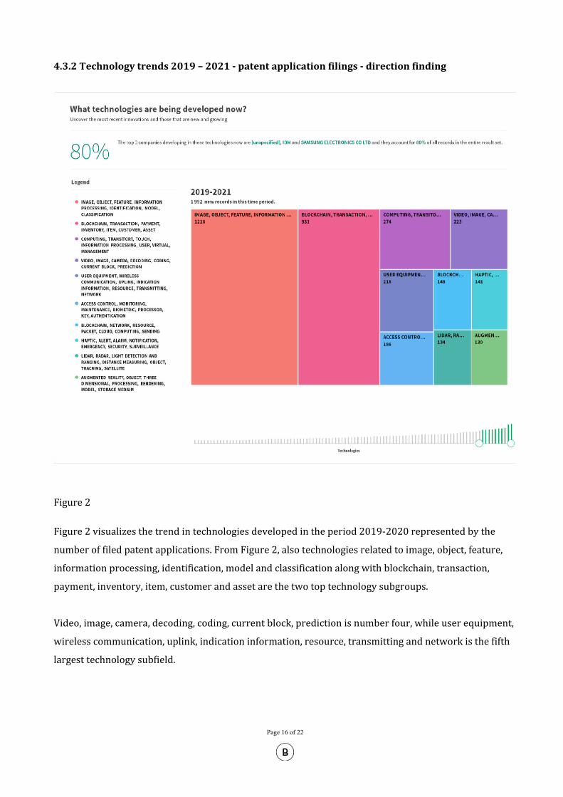
4.3.2Technologytrends2019–2021‐patentapplicationfilings‐directionfinding
Figure 2 Figure 2 visualizes the trend in technologies developed in the period 2019-2020 represented by the
number of filed patent applications. From Figure 2, also technologies related to image, object, feature,
information processing, identification, model and classification along with blockchain, transaction,
payment, inventory, item, customer and asset are the two top technology subgroups.
Video, image, camera, decoding, coding, current block, prediction is number four, while user equipment,
wireless communication, uplink, indication information, resource, transmitting and network is the fifth
largest technology subfield.

Page 17 of 22
4.3.3The20companieswithlargestnumbersofpatentapplicationfilings2000–2021involvingdirectionfinding
Figure 3 As can be seen from Figure 3, several mobile phones manufacturing companies are among the largest
filers in the entire technical field searched seen over the period of 20 years. Samsung, Nokia Corp, LG
Electronics Inc. and Apple are listed.

Page 18 of 22
5.0 New technology solutions for finding tagged items using phone 5.1 A growing marked is use of mobile phones for localization of lost tagged objects. The main players providing this technology are Samsung, Apple, and Tile. Samsung:
Galaxy SmartTags. Locate items by use of Bluetooth (BT) technology. Galaxy SmartTags Plus: Locate items using Ultra-Wideband (UWB).1
Apple:
“AirTags”: Locate items using Bluetooth BT and UWB.2. Tile
Tile trackers using Bluetooth (BT). Tiles will probably launch tags with UWB later this year competing with Samsung and Apple.3 (www.tile.com)
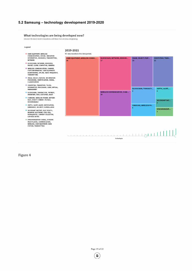
These trends coincide with the patent application activity for Samsung, Apple and Tiles for 2019-2020. The number of patent applications for the technical field involving tags and RFID/Bluetooth/UWB are visualized in Figures 4, 5 and 6 respectively divided into subgroups covering different technical fields for such technologies. The main technical subfield for Samsung, Apple and Tiles is user equipment, wireless communication, uplink, indication information, resource, transmitting, network. Patent activity within this technical subfield may be an indicator of a potentially valuable market for the personalized use of tags for localization of objects using your own mobile phone. Some of these localization technologies may potentially combine direction finding with AR technology of mobile phones to visualize and identify where the tagged object(s) is located. This might potentially involve combination of image with information about tagged objects and the relative position of these objects within the frame of the image as seen through the field of view of an image registration device. Such technology is patented by IDTAG.
1 Samsung: https://www.vrroom.buzz/vr-news/tech/samsung-debuts-smarttags-ar-finder-apple
https://www.cnet.com/how-to/how-samsung-smarttag-bluetooth-trackers-work-and-how-to-buy-them/; https://insights.samsung.com/2021/01/25/what-is-ultra-wideband-and-how-does-it-work-2/
2 Apple: https://www.macrumors.com/guide/airtags/ https://developer.apple.com/documentation/nearbyinteraction/ninearbyobject
3 Tile: https://techcrunch.com/2021/01/05/tile-to-launch-to-launch-a-new-tracker-powered-by-ultra-wideband-technology/amp/;
Page 19 of 22
5.2 Samsung – technology development 2019-2020
Figure 4

Page 20 of 22
5.3Apple– technology development 2019-2020
Figure 5

Page 21 of 22
5.4Tiles‐technology development 2019-2020
Figure 6

Page 22 of 22
Theassessmentsprovidedinthisreportarebasedonourprofessionalopinion,takingintoconsiderationapplicableregulations,caselawandcurrentadministrativepractice.However,assessmentsregardingthescopeofprotectionforpatentsandlikelihoodofinfringementarehighlydiscretionary,andtheoutcomeofaspecificassessmentmaybedifficulttopredictwithahighdegreeofcertainty.Werelyonavailabledatainseveraldatabasesmaintainedbythirdparties.BrynAarflotthereforedisclaimsallliabilityfortheconclusionsinthisreport. May 11, 2021 Yours sincerely, Bryn Aarflot AS
Kristine Rekdal European Patent Attorney
Appendix - Enclosures: 1. Letter from Dr. Bengt Holter, Research Manager, Communication systems, SINTEF Digital 2. Citations by the European Patent Office 3. Derwent files: Citations during prosecution of patent family applications. 4. Citing publications: Patent publications citing a publication of the IDTAG patent family

APPENDIX 1

PROJECT NO. / FILE CODE
102021274 1 of 2
SINTEF Digital SINTEF Digital
Postboks 124 Blindern NO‐0314 Oslo NORWAY
Location: 1
40005100 210246
No: NO 919 303 808 MVA
On the ID‐TAG patent
The ID-TAG patent is ahead of its time by 10 years, since the technology, ideas and concepts envisioned by this patent are only now finally on the verge of becoming a reality. ID-TAG envisioned a scenario and an associated marketplace within the internet of things (IoT) where objects were tagged, and that the information associated with the objects (through the tag) could be presented in real-time through an image or a video display. As such, IoT objects could become a source of information by enabling them to communicate with humans when they are present and located inside the two most important media formats currently in use: images and videos.
Previously, interaction with IoT objects was conducted purely either in the optical domain (by taking images of QR codes) or the electromagnetic domain (using RFID or NFC technologies). The ID-TAG patent combines the electromagnetic and optical domains to create a marketplace for tagged IoT objects present in images or videos. This marketplace could be exploited by manufacturers of consumer applications involving mobile phones, cameras, wearables, etc. However, the patent may also be exploited by manufacturers of industrial applications, targeting services such as predictive maintenance, drone inspections, security cameras and e-health, to name a few.
In short, the ID-TAG patent is relevant and powerful when targeting applications which require a combination of an image/video and a direction to tagged objects.
More and more objects are being connected to the internet, and short-range wireless technologies developed for the internet of things (IoT) has allowed us humans to interact with an ever-increasing number of devices. One of the most dominating short-range wireless technologies is Bluetooth, and this technology has through the last decade enabled many applications to shift from a wired to a wireless solution. In the beginning, Bluetooth could be looked upon as a blind technology, i.e., a connection could be established to nearby objects if they were in range, but the direction to the objects was not an issue. Hence, the use of a single antenna with an omni-directional radiation pattern was sufficient. Lately, direction finding techniques have started to emerge as a strong enabler for new short-range IoT-applications, and one of the main contributors to this trend happened when Bluetooth introduced direction finding features as part of their standard. Suddenly, Bluetooth was not a blind technology anymore. It could be used to see where (in terms of electromagnetic sensing) the objects were located nearby. So far, the main application of this new technology has been tracking of objects, i.e., finding items in a warehouse or locating personal belongings. Major players in the market like Apple, Samsung and Tile have started to capitalize on the trend of locating things by developing applications based on this technology. They are also actively pushing this market and building eco-systems by introducing their own tags to be attached to objects. It is however just recently that ideas emerged from these players have started to resemble the ideas described and captured by the ID-TAG patent, which is to combine electromagnetic and
ID‐TAG TECHNOLOGY GROUP AS Forskningsveien 0373 Oslo
Gjørtlervegen 13 Switchboard: +47
2618 Lillehammer Direct line: +47 93
Att. Erik Johannesen [email protected]
Enterprise /VAT
Your ref. EJ
Our ref. BH
Project No. / File code 102021274
Date 2021‐05‐10

PROJECT NO. / FILE CODE
102021274 2 of 2
optical sensing and present the captured information in real-time in an image or a video (using AR/VR techniques as an overlay).
As the mobile generations have evolved from 1G to 5G, humans have increasingly used images and videos to consume information. Combined with direction finding methods enabled by Bluetooth and ultra-wide band (UWB) technologies, the trend is now to develop applications which can capture information passively or actively by interacting with objects only in a specific direction, and in particular objects which are visible and located in real-time through an image or a video display. An image or a video display is a powerful tool to present information, and since essentially all applications on a smart phone convey the information to the user through this display, the information must be presented effectively on this screen. The ID-TAG patent contains claims which directly relate to how to capitalize on this trend and this type of applications.
With the advent of 5G, this trend seems just to be in its infancy. Currently, 5G is being rolled out as a non-standalone version (a mix of 4G and 5G) using newly allocated frequencies in the sub-6GHz range to increase the capacity in the consumer market. However, when the fully evolved 5G standalone version is available, the full market potential is released which includes communications in the millimetre wave range as well. This technology is based on highly directional beams, so the trend of developing applications based on direction finding methods is likely to increase in strength over time. It is also highly likely that this trend will penetrate not just the consumer market, but also the industrial market.
Bengt Holter Bengt Holter (May 10, 2021 19:59 GMT+2)
Dr. Bengt Holter1
Research Manager Communication systems SINTEF Digital
AboutSINTEFSINTEF is a broad, multidisciplinary research organisation with international top-level expertise in the fields of technology, the natural sciences, medicine and the social sciences. SINTEF is located in Trondheim in mid-Norway (1400 employees) and in Oslo (400 employees). It consists of several research institutes, and we have personel in offices and subsidiary companies in Bergen, Tromsø, Ålesund, Raufoss, Mo i Rana, Porsgrunn, Brussels and Hirtshals (Denmark). SINTEF also operates a research station in Svalbard. We conduct contract R&D as a partner for the private and public sectors, and we are one of the largest contract research institutions in Europe. We deliver innovation by developing knowledge and technologies that are brought into practical use, and our vision is Technology for a better society.
SINTEF Digital conducts research and innovation in digital technologies and technology-oriented social sciences. Our multi-disciplinary knowledge base is used across all industries and helps our customers exploit and meet opportunities created by digitalization and digital transformation.
1 Co-inventor of the ID-TAG patent

APPENDIX 2

22.3.2021 Citations - European Patent Register
https://register.epo.org/application?number=EP13833690&lng=en&tab=citations 1/1
Extract from the Register of European Patents
Citations: EP2890953
Cited in
Search
Type: Patent literature
Publication No.:WO2010105633 [XI]
(NOKIA CORP [FI], et al) [X] 39 * abstract * * page 1, line 5 - line 10 * * page 2, line 15 -page 3, line 26 * [I] 1-38,40;
Type: Patent literature
Publication No.:WO2005045455 [A]
(CAMBRIDGE CONSULTANTS [GB], et al) [A] 1-40 * abstract * * page 2, line 19 - page3, line 2 * * page 4, line 11 - line 32 *;
Type: Patent literature
Publication No.:US2008211631 [A]
(SAKAMOTO MASASHI [JP]) [A] 1-40 * abstract * * paragraph [0032] - paragraph[0038] * * paragraph [0042] * * paragraph [0050] - paragraph [0051] *
Cited in
International search
Type: Patent literature
Publication No.: KR20120115702 [XP] (LG ELECTRONICS INC [KR]);
Type: Patent literature
Publication No.: US2005229227 [X] (ROGERS BRIAN [US]);
Type: Patent literature
Publication No.: WO0135054 [X] (ARMSTRONG BRIAN S [US], et al);
Type: Patent literature
Publication No.: US2004169587 [X] (WASHINGTON RICHARD G [US]);
Type: Patent literature
Publication No.: US6397334 [A] (CHAINER TIMOTHY JOSEPH [US], et al);
Type: Patent literature
Publication No.: US2005104956 [A] (ONO SHUJI [JP], et al);
Type: Patent literature
Publication No.: US7388496 [A] (HALCROW MICHAEL A [US], et al);
Type: Patent literature
Publication No.: US2009009626 [A] (KO CHANG-SEOG [KR], et al)
Type: Non-patent literature
Publication information:[X] - NIKITIN PAVEL V. ET AL., "Phase Based Spatial Identification of UHF RFID Tags",2010 IEEE INTERNATIONAL CONFERENCE ON RFID, (20100414), pages 102 - 109,XP031677646

APPENDIX 3

Derwent Innovation Patent Export, 2021-03-13 14:42:36 +0000
Record 1/31 US7873326B2
Publication Number: US7873326B2
Title - DWPI: Information e.g. signal phase information, deriving method for radio frequency
identification system, involves deriving information of radio frequency identification tag from
combination of processed received signals
Priority Number - DWPI: US2006807064P | US2007770712A
Priority Date - DWPI: 2006-07-11 | 2007-06-28
Inventor - DWPI: GEVARGIZ J | MANTEGHI M | SADR R
Assignee - DWPI: MOJIX INC | SADR R
Abstract - DWPI:
Abstract - DWPI Novelty:
The method involves transmitting radio frequency identification (RFID) tag interrogation signals
from an array of antenna elements to the tag. The signals received by each of the antenna
elements from the RFID tag are processed to alter relative phase between the signals. Information
of the RFID tag is derived from a combination of processed received signals. The signals from one
of the antenna elements are selected as a reference signal. A relative phase of the signals is
adjusted from other antenna elements relative to the reference signal.
Abstract - DWPI Detailed Description:
An INDEPENDENT CLAIM is also included for a radio frequency identification (RFID) system
comprising an antenna array with a set of antenna elements.
Abstract - DWPI Use:
Method for deriving information such as radio frequency identification (RFID) tag information,
signal phase information, real valued information, range information, and arrival information, from
a radio frequency identification (RFID) tag such as stationary RFID tag and mobile RFID tag, in a
RFID system.
1

Abstract - DWPI Advantage:
The method improves accuracy of relative direction of the arrival information derived from the
signals at each antenna element after the radio frequency identification (RFID) information is
derived. The method reduces effects of interference in signals and/or maximizes a ratio of the
signals received from the RFID tags compared to interference and noise. The method provides
substantial bandwidth utilization improvements over single antenna systems, and enhances the
overall performance of the RFID system. The method reduces a resonant frequency and
bandwidth of an antenna patch, and miniaturizes the antenna while maintaining a wide bandwidth.
Abstract - DWPI Drawing Description: The drawing shows a block diagram of a radio frequency
identification (RFID) system.
1-1 Pallet of goods
1-2 Interferer
1-4 Transmitted interrogation signal
1-6 Antenna
2

Record 2/31 US20100103173A1
Publication Number: US20100103173A1
Title - DWPI: Method of tracking object in image for interactive video applications, involves
mapping object determined using trilateration techniques from three-dimensional (3D) space onto
two-dimensional (2D) virtual screen
Priority Number - DWPI: US2008258652A
Priority Date - DWPI: 2008-10-27
Inventor - DWPI: LEE J | LEE M | LEE W
Assignee - DWPI: ALCATEL-LUCENT USA INC | LEE J | LEE M | LEE W
Abstract - DWPI:
Abstract - DWPI Novelty:
The location of an object in 3D space is determined (201) based on trilateration of emissions from
a radio frequency (RF) tag device attached to the object by a positioning block. The location and
orientation of a camera is determined. The location of the object from three-dimensional space is
mapped (202) onto a 2D virtual screen defined by the location and orientation of the camera by a
computing block. The mapped location and an image of the object are recorded (204)
simultaneously in a media storage.
Abstract - DWPI Detailed Description:
An INDEPENDENT CLAIM is included for system for tracking object in image.
Abstract - DWPI Use:
Method of tracking object in image, using radio technologies such as radio-frequency identification
(RFID), Bluetooth or ultra-wide band (UWB) for interactive TV applications and streaming
video. Can also be used in applications such as advertising and marketing through interactive
video.
Abstract - DWPI Advantage:
An accurate real-time tagging, positioning and tracking of objects are achieved by mapping object
determined using trilateration techniques from 3D space onto 2D virtual screen, thus eliminating
the consumption of time and/or error-prone post processing steps involved in locating objects in
3

the video. The advertisers are assisted to track the amount of time that their products are seen on
the screen.
Abstract - DWPI Drawing Description: The drawing shows a flowchart illustrating process of
tracking object in image.
201 Determining location of tagged object in 3D object
202 Mapping 3D location to virtual 2D camera screen
203 Capturing image
204 Recording image and 2D object location
4

Record 3/31 US20070288499A1
Publication Number: US20070288499A1
Title - DWPI: Media/multimedia file tagging method for e.g. displaying picture, involves
determining whether data containing radio frequency identification transponder tag, is present in
within range of tag reader
Priority Number - DWPI: US2006804292P | US2006458716A
Priority Date - DWPI: 2006-06-09 | 2006-07-20
Inventor - DWPI: DUNKO G | DUNKO G A
Assignee - DWPI: SONY ERICSSON MOBILE COMMUNICATIONS AB
Abstract - DWPI:
Abstract - DWPI Novelty:
The method involves creating a media file using a device e.g. digital camera with a radio
frequency identification (RFID) transponder tag reader, and determining whether data containing
RFID transponder tag e.g. text, is present within range of the tag reader. A connection is
established between the data containing RFID transponder tag and the tag reader. The data from
the RFID transponder tag is received via the tag reader. The received RFID transponder tag data
is attached to the media/multimedia file to create a tagged media/multimedia file.
Abstract - DWPI Detailed Description:
INDEPENDENT CLAIMS are also included for the following: a computer program product
comprising a computer program code for creating a media/multimedia filea system for tagging a
media/multimedia file.
Abstract - DWPI Use:
Used for tagging a media/multimedia files such as digital picture taken by an associated
digital/video camera device, digital still camera, mobile camera phone, video file, audio file such as
music, sound recording and text files to be displayed to remote users of computer connected in
local area network (LAN), wide area network (WAN) and server.
Abstract - DWPI Advantage:
The tag attached to media/multimedia files sent to other computer users, allows the users to view
5

a text scroll at the bottom of the display, which can provide the user with the radio frequency
identification (RFID) transponder tag content data or an audible description of the related file. The
user can see the picture and receive information about date and time of the picture
contemporaneously
Abstract - DWPI Drawing Description: The drawing shows a block diagram of the RFID reader
equipped mobile phone or digital/video camera.
6

Record 4/31 WO2001035054A9
Publication Number: WO2001035054A9
Title - DWPI: Image metrology reference target for facilitating measurements of orientation and
distance has radiation source that emanates from observation surface radiation having at least
one detectable property in image of reference target
Priority Number - DWPI: US1999164754P | US2000212434P | US2000711857A |
US2004865733A
Priority Date - DWPI: 1999-11-12 | 2000-06-16 | 2000-11-13 | 2004-06-09
Inventor - DWPI: ARMSTRONG B S | ARMSTRONG B S R | SCHMIDT K B
Assignee - DWPI: GO SENSORS LLC | ARMSTRONG B S | SCHMIDT K B
Abstract - DWPI:
Abstract - DWPI Novelty:
At least one orientation dependent radiation source is disposed in a set spatial relationship with
respect to the at least one fiducial mark (20A,B). The radiation source emanates from an
observation surface radiation having at least one detectable property in an image of the reference
target. It provides at least one of a rotation angle of the orientation dependent radiation source and
a distance between the orientation dependent radiation source and a camera (22) obtaining the
image of the reference target.
Abstract - DWPI Detailed Description:
INDEPENDENT CLAIMS are included for: a method for processing an image including at least
one orientation dependent radiation source that emanates from an observation surface orientation
dependent radiationa computer readable storage medium
Abstract - DWPI Use:
For orientation and distance measurements for image metrology applications.
Abstract - DWPI Advantage:
Does not require significant computing resources, skilled staff using complex and often expensive
equipment and instrumentation. Facilitates an automatic detection of a reference target in an
image of the reference target obtained by a camera for facilitating a determination of at least one
7

of a position and at least an orientation angle of the reference target with respect to a camera.
Abstract - DWPI Drawing Description: The drawing is a diagram illustrating an example of an
image metrology apparatus according to one embodiment of the present invention.
20A,B fiducial mark
22 camera
8

Record 5/31 WO2005045455A2
Publication Number: WO2005045455A2
Title - DWPI: Positional information determining apparatus for object, has processor which obtains
value of parameter representative of signal received at receiving unit, and compares values of
obtained parameter
Priority Number - DWPI: GB200325622A
Priority Date - DWPI: 2003-11-03
Inventor - DWPI: BELL C | BELL C P | BURCHETT M | BURCHETT M H | DEL MISTRO M |
GEOGHEGAN A | GEOGHEGAN A J | GEORGEGAN A J | MARIO D M | MICHAEL H B |
NICHOLAS S R | OOTOSH P U V | OSWALD G | OSWALD G K A | PHILIPS D K | PHILLIPS D |
PHILLIPS D K | RUSS N | RUSS N S | UTSI P A V | UTSI V A
Assignee - DWPI: CAMBRIDGE CONSULTANTS | BELL C P | BURCHETT M H | DEL MISTRO
M | GEOGHEGAN A J | OSWALD G K A | PHILLIPS D K | RUSS N S | UTSI V A
Abstract - DWPI:
Abstract - DWPI Novelty:
The apparatus (200) includes a detector which detects signals (106) received at the receiving units
of a receiver (200,202) and generates output signals based on the received signals. A processor
obtains value of a parameter representative of the signal received at the receiving unit, and
compares the values of the obtained parameter to determine the positional information of the
object (102).
Abstract - DWPI Detailed Description:
INDEPENDENT CLAIMS are also included for the following: a positional information determining
method;a detection volume searching apparatus;a detection volume searching method;a signal;
anda computer program.
Abstract - DWPI Use:
For object.
Abstract - DWPI Advantage:
Allows using one sensor installation. Improves accuracy of determining object position. Does not
9

require exploiting multipath to improve apparatus performance.
Abstract - DWPI Drawing Description: The figure shows the block diagram of the positional
information determining apparatus.
102 Object
106 Signals
200 Positional information determining apparatus
200,202 Receiver
10

Record 6/31 WO2014121521A1
Publication Number: WO2014121521A1
Title - DWPI: Method for instantly recognizing and positioning object, involves calculating distance
between plane defined by axes of object and position in which images of object is located to
determine coordinate for object is captured
Priority Number - DWPI: WO2013CN71583A | CN201380072591A
Priority Date - DWPI: 2013-02-08 | 2013-02-08
Inventor - DWPI: FENG C | FENG Z | FUNG C | FUNG W | FUNG W T
Assignee - DWPI: FENG C | FENG Z | FUNG C
Abstract - DWPI:
Abstract - DWPI Novelty:
The method involves transforming (S104) captured images of object according to two-dimensional
(2D) center coordinate of object to acquire a three-dimensional (3D) pattern of object, and 3D
pattern of the object is compared with 3D patterns pre-stored. A distance is calculated between a
plane defined by axes of object and a position in which the images of object is located to
determine a coordinate for the object is captured when 3D pattern of object matches with pre-
stored 3D pattern. A 3D center coordinate of the object is obtained to recognize and position the
object.
Abstract - DWPI Detailed Description:
An INDEPENDENT CLAIM is included for a system for instantly recognizing and positioning an
object.
Abstract - DWPI Use:
Method for instantly recognizing and positioning object.
Abstract - DWPI Advantage:
The method allows for instantly recognizing, positioning and controlling an object using one
camera only, requiring no complicated hardware installation and software setup, thus the user is
easily control the active object in real scene after automatically positioning the object. Since the
system detects whether a door or a window is properly closed when the user is leaving home and
11

detects whether the electronic appliance such as TV set or DVD are on when the user is not at
home, the user is ablr manage and control his/her home efficiently and smartly with the aid of the
system.
Abstract - DWPI Drawing Description: The drawing shows a flowchart illustrating the method for
instantly recognizing, positioning and controlling an object.
S101 Step for wirelessly searching a wireless identification of the object
S102 Step for capturing images of the object by rotating a predetermined angle for each image
capture
S103 Step for determining two-dimensional center coordinate of the object based on a center
coordinate of the wireless identification of the object
S104 Step for transforming the captured images of the object and comparing the pattern of the
object with three-dimensional patterns pre-stored
S106 Step for visibly controlling electric objects in real time
12

Record 7/31 RU2253149C2
Publication Number: RU2253149C2
Title - DWPI: Radio pollable surface wave component with optimal code range, e.g. for level
measurement has reflector structure with reflector code elements in raster with equidistant base
values
Priority Number - DWPI: DE19860058A
Priority Date - DWPI: 1998-12-23
Inventor - DWPI: REINDL L | SCHMIDT F | SCZESNY O | VOSSIEK M
Assignee - DWPI: SIEMENS AG | REINDL L | SCHMIDT F | SCZESNY O | VOSSIEK M
Abstract - DWPI:
Abstract - DWPI Novelty: The component has a substrate plate (10) with piezoelectric material
properties in its surface, (an) electroacoustic transducer(s) (12) with an interdigital structure for
generating a surface wave (15) with propagation direction defined by the structure and a reflector
structure (20) with reflectors as code elements in a raster with equidistant base values aligned with
the main propagation direction. The raster size is determined from the distance covered by the
surface wave in the time defined by the system measurement inaccuracy.Only those positions are
occupied for which the distance between reflectors is at least the structural resolution defined by
the system frequency bandwidth.
Abstract - DWPI Use: USE
E.g. for level measurement.
Abstract - DWPI Advantage: ADVANTAGE
Large code range is achieved with smaller than usual substrate plate length or size.
13

Record 8/31 US5659520A
Publication Number: US5659520A
Title - DWPI: Platform-based acoustic navigation system for underwater navigation uses
transmitter responsive to detection of interrogation signal, two receiver devices which calculate
spectral and spatial features, and measure round-trip delay
Priority Number - DWPI: US1995426957A
Priority Date - DWPI: 1995-04-24
Inventor - DWPI: CYR R J | DOUGLAS B L | LOGGINS C D | NORRIS D O | WAPNER M P |
WATSON M L
Assignee - DWPI: SONATECH INC
Abstract - DWPI:
Abstract - DWPI Novelty: The system includes a transmitter, a receiver and a computer which
receives outputs from the receiver. The transmitter device transmits an interrogation signal for
detection by a number of transponders or responders each of which transmits a reply signal
having at least one wave frequency component. The first receiver device comprises of receiving
elements spaced apart about 0.5 to 10 wavelengths of the lowest frequency component of the
reply signals.It comprises direction-of-arrival measurement including measuring phase difference
of the reply signal between each pair of receiving elements and thus estimates to resolve
ambiguities. The second receiver measures round-trip times providing distance-to-target estimates
for each target and a computer for correcting fine time-difference-of-arrival ambiguity.
Abstract - DWPI Advantage: ADVANTAGE
Provides improved accuracy over both short baseline navigation and super-short-baseline
navigation as interference between direct reply return signal and reflection path signal is
eliminated.
14

Record 9/31 RU2457472C2
Publication Number: RU2457472C2
Title - DWPI: Parameters (e.g. conductivity) measuring system includes sensor which is in
conjunction with tag and in proximity to impedance analyzer and reader that constitute
measurement device
Priority Number - DWPI: US2006866714P | WO2007US85199A | US2009447031A |
US13452467A
Priority Date - DWPI: 2006-11-21 | 2007-11-20 | 2009-04-24 | 2012-04-20
Inventor - DWPI: PIZZI V F | POTYRAILO R A | RICE S T | WANG H
Assignee - DWPI: GE HEALTH CARE BIOSCIENCE CORP | GE HEALTHCARE BIO-SCI CORP
Abstract - DWPI:
Abstract - DWPI Novelty:
A measuring system (100) comprises a container (101) having a solution (101a); and a protective
layer which is attached to a wall of the container to form a seal between the container and a
sensor (103). The sensor has an operable electromagnetic field based on a thickness of the
container and the protective layer. The sensor in conjunction with a tag (102) is in proximity to an
impedance analyzer (108) and a reader (106) that comprise a measurement device (111). It
determines parameter(s) of the solution. The tag provides a digital identification associated with
the sensor.
Abstract - DWPI Detailed Description:
A measuring system (100) comprises a container (101) having a solution (101a); and a protective
layer deposited over sensor(s) (103) and wall(s) of the container. The protective layer is attached
to the wall of the container to form a seal between the container and the sensor. The sensor has
an operable electromagnetic field based on a thickness of the container and the protective layer.
The sensor in conjunction with a tag (102) is in proximity to an impedance analyzer (108) and a
reader (106) that comprise a measurement device (111). It determines parameter(s) of the
solution. The tag provides a digital identification associated with the sensor. The impedance
analyzer receives a given range of frequencies from the sensor based on the parameter and
calculates parameter changes based on the measured complex impedance over the given range
of frequencies. An INDEPENDENT CLAIM is included for a method for assembling a system for
measuring parameters, comprising: providing sensor(s) which is placed in between two layers of
film;providing the first layer of film and the second layer of film with a predetermined
15

thickness;forming the first layer over the at least one sensor into the second layer;providing a third
layer of film which is formed into the first layer of film that forms a container with the third layer of
film; andproviding a solution into the container, where the first layer of film and the sensor
measure parameter(s) of the solution.
Abstract - DWPI Use:
System for measuring parameters, e.g. conductivity measurement, pH level, temperature, blood
relevant measurement, biological measurement, ionic measurement, pressure measurement, non-
ionic measurement or non-conductivity measurement.
Abstract - DWPI Advantage:
The system enables the user to simply and non-invasively test for chemical and/or biological
material in a solution in a disposable bio-processing system where the user can safely obtain
measurements for the material, then dispose of the bio-processing system.
Abstract - DWPI Drawing Description: The drawing is a block diagram of a system for assembling
and utilizing sensors in a container.
100 Parameters measuring system
101 Container
101a Solution
102 Tag
103 Sensor
106 Reader
108 Impedance analyzer
111 Measurement device
Abstract - DWPI Tech Focus: BIOTECHNOLOGY -
Preferred Component: The solution is fluid, blood or gas. The solution is blood that comprises
creatineine, urea, lactate dehydrogenase and alkaline potassium. The solution contains
prokaryotic cells or eukaryotic cells. INORGANIC CHEMISTRY -
Preferred Component: The solution is gas or dissolved gas that comprises carbon dioxide,
oxygen, or nitrogen oxide (NO x ). The solution includes a toxic industrial agent comprising
16

ammonia. A sensor coating is included comprising inorganic film.INSTRUMENTATION AND
TESTING -
Preferred System: The impedance analyzer is connected to a computer. The container is a
filtration device, chromatography device or centrifuge device and any associated transfer conduits
associated with them. ORGANIC CHEMISTRY -
Preferred Component: The toxic industrial agent may comprise acetone cyanohydrin. The sensor
coating may comprise organic film. POLYMERS -
Preferred Component: The sensor coating may comprise polymer film, biological composite film or
nano-composite film. It further comprises hydrogel film, sol-gel film, carbon black-polymer film,
carbon nanotube-polymer film, metal nanoparticle-polymer film, or electrospun nanofibers film.
Preferred Material: The container is made of plastic, polyethylene, low-density polyethylene, ultra
low-density polyethylene, polypropylene, polyester, polyamide, polycarbonate or elastomeric
materials. The protective layer is made of polytetrafluoroethylene or composite films.
17
Record 10/31 CN1893587A
Publication Number: CN1893587A
Title - DWPI: Video display apparatus for providing product information and method for controlling
the apparatus to provide various video contents related to a product and make electronic
commerce possible by sensing an rfid tag attached to the product
Priority Number - DWPI: KR2005109680A
Priority Date - DWPI: 2005-11-16
Inventor - DWPI: CHO R M | JO K M
Assignee - DWPI: LG ELECTRONICS INC | NANJING LG TONGTRU COLOR DISPLAY
SYSTEM
Abstract - DWPI:
Abstract - DWPI Novelty:
A video display apparatus capable of providing product information and a method for controlling
the apparatus are provided to display various video contents related to a product by sensing an
RFID(Radio Frequency IDentification) tag attached to the product, thereby enabling a user to
easily obtain information of the product and buy the product.
Abstract - DWPI Detailed Description:
An RFID reader(120) senses information of an RFID tag attached to a product. A supplemental
information storing part(130) stores supplemental information of video contents. A control
part(170) searches the supplemental information storing part in order to identify whether there are
video contents associated with the sensed information of the RFID tag, and controls the video
contents associated therewith to be displayed or stored according to a result of the search. A
signal processing part(112) processes a signal according to a control signal from the control part
so that the video contents associated with the sensed information of the RFID tag are displayed. A
PVR(Personal Video Recorder)(140) records and reproduces the video contents associated with
the sensed information of the RFID tag.Image 1/1
18

Record 11/31 WO2012155343A1
Publication Number: WO2012155343A1
Title - DWPI: Image processing system for use in monitoring system, has microprocessor module
that is coupled to radio frequency identification reader unit to receive image data and correlate tag
data with image data to generate combination data
Priority Number - DWPI: WO2011CN74213A
Priority Date - DWPI: 2011-05-18
Inventor - DWPI: B | BURNSIDE W D | D. W | H | HE Y | HO Y | HO Y M | Y
Assignee - DWPI: WISTRON NEWEB CORP | BURNSIDE W D | DJB GROUP | DJB GROUP
CO LTD | HO Y
Abstract - DWPI:
Abstract - DWPI Novelty:
The system (160) has a radio frequency identification (RFID) reader unit that retrieves tag data
including timing stamp information. A microprocessor module is coupled to the RFID reader unit
for receiving image data and correlating the tag data with the image data to generate combination
data. The combination data includes the information of the tag data and the image data. A memory
unit is coupled to the microprocessor module for storing the combination data. An Ethernet port
sends the combination data to a host computer.
Abstract - DWPI Detailed Description:
An INDEPENDENT CLAIM is included for monitoring system.
Abstract - DWPI Use:
Image processing system for use in monitoring system (claimed).
Abstract - DWPI Advantage:
Since the combination data includes timing stamp information and identities, the user or owner can
easily find out the exact location where the intruder is located and when exactly the intruder
breaks in.
Abstract - DWPI Drawing Description: The drawing shows a schematic view of monitoring system.
19

10 Monitoring system
100 RFID tag
120 Antenna array
140 Camera set
160 Image processing system
20

Record 12/31 KR2012115702A1
Publication Number: KR2012115702A1
Title - DWPI:
Priority Number - DWPI:
Priority Date - DWPI:
Inventor - DWPI:
Assignee - DWPI:
Abstract - DWPI:
21

Record 13/31 CN101374230A
Publication Number: CN101374230A
Title - DWPI: Image pickup system for e.g. industrial automation, has memory unit for memorizing
audio, video files and image files, and sever for storing mediums that are collected by system
through radio network transmission
Priority Number - DWPI: CN200810061852A
Priority Date - DWPI: 2008-06-02
Inventor - DWPI: QIU G
Assignee - DWPI: QIU G
Abstract - DWPI:
Abstract - DWPI Novelty:
The system has a display unit (400) for displaying recorded video, audio or images, and displaying
strength degrees of radio frequency signal through a radio frequency signal indicator (410). The
display unit calculates distance from a radio frequency transmission end according to the signal
strength of the radio frequency signal. An operation unit (700) deletes files and sets system
parameters. A memory unit (600) memorizes audio, video files and image files. A sever (800)
stores mediums that are collected by the system through a radio network transmission.
Abstract - DWPI Detailed Description:
An INDEPENDENT CLAIM is also included for a method for hiding radio frequency information in
a frame or a shot image of a recorded video or audio.
Abstract - DWPI Use:
Image pickup system for identifying radio frequency information and hiding radio frequency
information that is utilized in fields of industrial automation, paying and evidence collecting.
Abstract - DWPI Advantage:
The system facilitates relevant information of radio frequency to be obtained directly from a file
when playing a video file or browsing an image file for integrative storage of image vector
information.
22

Abstract - DWPI Drawing Description: The drawing shows a block diagram of an image pickup
system.
400 Display unit
410 Radio frequency signal indicator
600 Memory unit
700 Operation unit
800 Sever
23

Record 14/31 US7388496B1
Publication Number: US7388496B1
Title - DWPI: Product placement props identifying system for use in e.g. software, has multiple
cameras, individually equipped with radio frequency identification readers, for filming or recording
scene for audio/video content
Priority Number - DWPI: US2007871424A
Priority Date - DWPI: 2007-10-12
Inventor - DWPI: HALCROW M A | KIRKLAND D | PARANJAPE A M
Assignee - DWPI: INT BUSINESS MACHINES CORP
Abstract - DWPI:
Abstract - DWPI Novelty:
The system (100) has multiple cameras (114,116), individually equipped with radio frequency
identification (RFID) readers (110,112), for filming or recording a scene for audio/video (A/V)
content. Multiple recording devices retain audio/video content and product placement props (102-
108) related information. The audio/video content is synchronized with the product placement
props related information to form program footage. The combined program footage retains the
product placement props related information.
Abstract - DWPI Use:
System for identifying product placement props in a scene, in software, firmware and hardware.
Abstract - DWPI Advantage:
The system enables to provide improved feedback to the advertisers about the airtime their
products are receiving and if a particular product placement was effective.
Abstract - DWPI Drawing Description: The drawing shows a block diagram of a product
placement props identifying system.
100 Product placement props identifying system
102-108 Product placement props
110,112 Radio frequency identification readers
114,116 Cameras
140 Data base
24

25

Record 15/31 KR2012115702A
Publication Number: KR2012115702A
Title - DWPI: Mobile terminal comprises control unit for indicating calculated location information
with tag on display section, where scanned tag is adhered to memory for storing image of camera
Priority Number - DWPI: KR201133171A
Priority Date - DWPI: 2011-04-11
Inventor - DWPI: YOO J
Assignee - DWPI: LG ELECTRONICS INC
Abstract - DWPI:
Abstract - DWPI Novelty:
The mobile terminal (100) comprises a control unit (180) for indicating calculated location
information with a tag on a display section (151). The identifying information is obtained from a
scan, where scanned tag is adhered to a memory (160) for storing image of a camera (121). The
terminal utilizes a signal, which maps the identifying information of a read part (182). The signal
and the tag are received through the read part, where object image is stored and selected
according to the tag information about mapped identifying information.
Abstract - DWPI Detailed Description:
An INDEPENDENT CLAIM is included for a method for controlling the mobile terminal.
Abstract - DWPI Use:
Mobile terminal.
Abstract - DWPI Advantage:
The mobile terminal comprises a control unit for indicating calculated location information with a
tag on a display section, and hence ensures finding of preferred object rapidly, and thus
convenience of user is improved.
Abstract - DWPI Drawing Description: The drawing shows a block diagram of the mobile terminal.
(Drawing includes non-English language text).
100 Mobile terminal
26

121 Camera
151 Display section
160 Memory
180 Control unit
182 Read part
27

Record 16/31 US20050104956A1
Publication Number: US20050104956A1
Title - DWPI: Imaging device e.g. camera phone specifies direction of photography subject, based
on changes in radio signals received from radio frequency ID tag attached to subject by radio
receiver and changes corresponding to moving amount of receiver
Priority Number - DWPI: JP2003338706A | JP2003338707A | JP2004256341A |
JP2004262139A | US2004951626A
Priority Date - DWPI: 2003-09-29 | 2003-09-29 | 2004-09-02 | 2004-09-09 | 2004-09-29
Inventor - DWPI: ARAGAI Y | ISOMURA A | MAEDA Y | MINO I | MINO K | ONO S | SHINKAI Y
Assignee - DWPI: FUJI FILM CORP | FUJI PHOTO FILM CO LTD
Abstract - DWPI:
Abstract - DWPI Novelty:
A calculation unit calculates moving amount of radio receiver that receives radio signals from radio
frequency ID tag (104) attached to photography subject (110), based on continuously acquired
moving image of subject. A specifying unit specifies the direction of subject, based on changes in
field intensities of radio signals received by the receiver and changes corresponding to calculated
moving amount of receiver.
Abstract - DWPI Detailed Description:
INDEPENDENT CLAIMS are also included for the following: information storage server;article
identification apparatus; andimaging device.
Abstract - DWPI Use:
E.g. camera phone.
Abstract - DWPI Advantage:
Enables correctly specifying the direction of the photography object and acquiring the image of the
photography object reliably.
Abstract - DWPI Drawing Description: The figure shows a schematic drawing of the information
providing system.
28

102 camera phone
104 RF ID tag
106 communication network
108 storage server
110 subject
29

Record 17/31 RU2004124049A
Publication Number: RU2004124049A
Title - DWPI:
Priority Number - DWPI:
Priority Date - DWPI:
Inventor - DWPI:
Assignee - DWPI:
Abstract - DWPI:
30

Record 18/31 US20080204322A1
Publication Number: US20080204322A1
Title - DWPI: Positional information determining apparatus for object, has processor which obtains
value of parameter representative of signal received at receiving unit, and compares values of
obtained parameter
Priority Number - DWPI: GB200325622A
Priority Date - DWPI: 2003-11-03
Inventor - DWPI: BELL C | BELL C P | BURCHETT M | BURCHETT M H | DEL MISTRO M |
GEOGHEGAN A | GEOGHEGAN A J | GEORGEGAN A J | MARIO D M | MICHAEL H B |
NICHOLAS S R | OOTOSH P U V | OSWALD G | OSWALD G K A | PHILIPS D K | PHILLIPS D |
PHILLIPS D K | RUSS N | RUSS N S | UTSI P A V | UTSI V A
Assignee - DWPI: CAMBRIDGE CONSULTANTS | BELL C P | BURCHETT M H | DEL MISTRO
M | GEOGHEGAN A J | OSWALD G K A | PHILLIPS D K | RUSS N S | UTSI V A
Abstract - DWPI:
Abstract - DWPI Novelty:
The apparatus (200) includes a detector which detects signals (106) received at the receiving units
of a receiver (200,202) and generates output signals based on the received signals. A processor
obtains value of a parameter representative of the signal received at the receiving unit, and
compares the values of the obtained parameter to determine the positional information of the
object (102).
Abstract - DWPI Detailed Description:
INDEPENDENT CLAIMS are also included for the following: a positional information determining
method;a detection volume searching apparatus;a detection volume searching method;a signal;
anda computer program.
Abstract - DWPI Use:
For object.
Abstract - DWPI Advantage:
Allows using one sensor installation. Improves accuracy of determining object position. Does not
31

require exploiting multipath to improve apparatus performance.
Abstract - DWPI Drawing Description: The figure shows the block diagram of the positional
information determining apparatus.
102 Object
106 Signals
200 Positional information determining apparatus
200,202 Receiver
32

Record 19/31 US20080211631A1
Publication Number: US20080211631A1
Title - DWPI: Radio tag communication apparatus for radio tag position estimation apparatus, has
tag response information transmitting unit that transmits communication direction information to
radio tag position estimation apparatus
Priority Number - DWPI: JP2006346528A
Priority Date - DWPI: 2006-12-22
Inventor - DWPI: SAKAMOTO H | SAKAMOTO M
Assignee - DWPI: OKI ELECTRIC IND CO LTD
Abstract - DWPI:
Abstract - DWPI Novelty:
The radio tag communication apparatus (101) consists of transmitting unit (101b) that irradiates
electromagnetic waves towards predetermined direction. A receiver (101d) receives the
transmitted electromagnetic wave. A tag response information transmitting unit transmits regarding
the direction of communication between the transmitting unit and receiver, to the radio tag position
estimation apparatus.
Abstract - DWPI Detailed Description:
INDEPENDENT CLAIMS are included for the following: radio tag position estimation
apparatus;radio tag position estimation method; andradio tag position estimation program.
Abstract - DWPI Use:
Radio tag communication apparatus for radio tag position estimation apparatus (claimed) for use
in goods management in supermarket and in book store or library.
Abstract - DWPI Advantage:
The position of the tag is identified regardless of arrangement, external appearance and packed
condition of the goods with radio tag.
Abstract - DWPI Drawing Description: The drawing shows a block diagram of radio tag position
estimation system. (Drawing includes non-English language text)
33

100 Radio tag position estimation system
101 Radio tag communication apparatus
101b Transmitting unit
101d Receiver
105b Radio tag
34

Record 20/31 WO2001035054A1
Publication Number: WO2001035054A1
Title - DWPI: Image metrology reference target for facilitating measurements of orientation and
distance has radiation source that emanates from observation surface radiation having at least
one detectable property in image of reference target
Priority Number - DWPI: US1999164754P | US2000212434P | US2000711857A |
US2004865733A
Priority Date - DWPI: 1999-11-12 | 2000-06-16 | 2000-11-13 | 2004-06-09
Inventor - DWPI: ARMSTRONG B S | ARMSTRONG B S R | SCHMIDT K B
Assignee - DWPI: GO SENSORS LLC | ARMSTRONG B S | SCHMIDT K B
Abstract - DWPI:
Abstract - DWPI Novelty:
At least one orientation dependent radiation source is disposed in a set spatial relationship with
respect to the at least one fiducial mark (20A,B). The radiation source emanates from an
observation surface radiation having at least one detectable property in an image of the reference
target. It provides at least one of a rotation angle of the orientation dependent radiation source and
a distance between the orientation dependent radiation source and a camera (22) obtaining the
image of the reference target.
Abstract - DWPI Detailed Description:
INDEPENDENT CLAIMS are included for: a method for processing an image including at least
one orientation dependent radiation source that emanates from an observation surface orientation
dependent radiationa computer readable storage medium
Abstract - DWPI Use:
For orientation and distance measurements for image metrology applications.
Abstract - DWPI Advantage:
Does not require significant computing resources, skilled staff using complex and often expensive
equipment and instrumentation. Facilitates an automatic detection of a reference target in an
image of the reference target obtained by a camera for facilitating a determination of at least one
35

of a position and at least an orientation angle of the reference target with respect to a camera.
Abstract - DWPI Drawing Description: The drawing is a diagram illustrating an example of an
image metrology apparatus according to one embodiment of the present invention.
20A,B fiducial mark
22 camera
36

Record 21/31 US20090009626A1
Publication Number: US20090009626A1
Title - DWPI: Image file generating method for e.g. personal digital assistant, involves generating
image data by taking picture of object, receiving object information from object through network,
and storing information in image file with data
Priority Number - DWPI: KR200766189A
Priority Date - DWPI: 2007-07-02
Inventor - DWPI: CHOI W | CHOI Y | CHOI Y J | GAO C | KIM Y | KIM Y S | KO C | KO C S |
PARK H | PARK H C
Assignee - DWPI: SAMSUNG ELECTRONICS CO LTD
Abstract - DWPI:
Abstract - DWPI Novelty:
The method involves generating image data by taking a picture of an object, where the object
includes Radio Frequency Identification (RFID) tag comprising object information, and a user
terminal including an RFID reader. An object information is received from the object through a
network that is a short- distance wireless network by utilizing one of a Wireless Local Area
Network (WLAN) method, Bluetooth method, Zigbee method and a Wireless Broadband (WiBro)
method. The object information is stored in an image file with the image data.
Abstract - DWPI Detailed Description:
INDEPENDENT CLAIMS are also included for the following: a method for outputting an image
filean apparatus for generating an image file, comprising an image file processing unit.
Abstract - DWPI Use:
Method for generating an image file including object information such as latitude, a longitude, an
altitude, and direction, about an object such as wireless communication device. Uses include but
are not limited to a personal digital assistant (PDA), portable multimedia player (PMP), cellular
phone, navigation device, personal computer (PC) and laptop.
Abstract - DWPI Advantage:
The method generates the image file including the about the wireless communication device in an
37

efficient manner.
Abstract - DWPI Drawing Description: The drawing shows a flowchart illustrating the steps
involved in a method for outputting an image file.
38

Record 22/31 WO2005045455A3
Publication Number: WO2005045455A3
Title - DWPI: Positional information determining apparatus for object, has processor which obtains
value of parameter representative of signal received at receiving unit, and compares values of
obtained parameter
Priority Number - DWPI: GB200325622A
Priority Date - DWPI: 2003-11-03
Inventor - DWPI: BELL C | BELL C P | BURCHETT M | BURCHETT M H | DEL MISTRO M |
GEOGHEGAN A | GEOGHEGAN A J | GEORGEGAN A J | MARIO D M | MICHAEL H B |
NICHOLAS S R | OOTOSH P U V | OSWALD G | OSWALD G K A | PHILIPS D K | PHILLIPS D |
PHILLIPS D K | RUSS N | RUSS N S | UTSI P A V | UTSI V A
Assignee - DWPI: CAMBRIDGE CONSULTANTS | BELL C P | BURCHETT M H | DEL MISTRO
M | GEOGHEGAN A J | OSWALD G K A | PHILLIPS D K | RUSS N S | UTSI V A
Abstract - DWPI:
Abstract - DWPI Novelty:
The apparatus (200) includes a detector which detects signals (106) received at the receiving units
of a receiver (200,202) and generates output signals based on the received signals. A processor
obtains value of a parameter representative of the signal received at the receiving unit, and
compares the values of the obtained parameter to determine the positional information of the
object (102).
Abstract - DWPI Detailed Description:
INDEPENDENT CLAIMS are also included for the following: a positional information determining
method;a detection volume searching apparatus;a detection volume searching method;a signal;
anda computer program.
Abstract - DWPI Use:
For object.
Abstract - DWPI Advantage:
Allows using one sensor installation. Improves accuracy of determining object position. Does not
39

require exploiting multipath to improve apparatus performance.
Abstract - DWPI Drawing Description: The figure shows the block diagram of the positional
information determining apparatus.
102 Object
106 Signals
200 Positional information determining apparatus
200,202 Receiver
40

Record 23/31 US20110001659A1
Publication Number: US20110001659A1
Title - DWPI: Device for directional estimation and/or decoding of secondary radar signal, has
processing unit for performing directional estimation, so that amplifications, phase differences and
varying noise ratios are considered during estimation
Priority Number - DWPI: DE102008010882A
Priority Date - DWPI: 2008-02-25
Inventor - DWPI: BEROLD U | HAMPEL H | RECK C | SCHMIDT L | WEINZIERL J
Assignee - DWPI: IAD GES INFORMATIK AUTOMATISIERUNG & DAT | IAD GES
INFORMATIK AUTOMATISIERUNG&DAT | IAD GMBH
Abstract - DWPI:
Abstract - DWPI Novelty:
The device has a signal processor (FPGA) connected with a phase lock loop-voltage controlled
oscillator circuit for controlling mixer frequency. A processing unit (CPU) receives data (DD) from
antenna elements (AE) and performs directional estimation using a subspace based method, so
that different amplifications, phase differences and varying noise ratios in analog input stages
connected to the antenna elements are considered during the directional estimation according to
cross bearing and during detection of received radio transmission data.
Abstract - DWPI Detailed Description:
An INDEPENDENT CLAIM is also included for a method for directional estimation and/or decoding
of a secondary radar signal.
Abstract - DWPI Use:
Device for directional estimation and/or decoding of a secondary radar signal.
Abstract - DWPI Advantage:
The device simultaneously performs directional estimation and/or decoding of secondary radar
signals, without the need for additional and separate receiving systems for directional estimation
and/or decoding of the secondary radar signals.
41

Abstract - DWPI Drawing Description: The drawing shows a schematic block diagram of a device
for directional estimation and/or decoding of a secondary radar signal.
AE Antenna elements
CPU Processing unit
DD Data
F1, F2 Bandpass filters
FPGA Signal processor
42

Record 24/31 CN101340500A
Publication Number: CN101340500A
Title - DWPI: Image file generating method for e.g. personal digital assistant, involves generating
image data by taking picture of object, receiving object information from object through network,
and storing information in image file with data
Priority Number - DWPI: KR200766189A
Priority Date - DWPI: 2007-07-02
Inventor - DWPI: CHOI W | CHOI Y | CHOI Y J | GAO C | KIM Y | KIM Y S | KO C | KO C S |
PARK H | PARK H C
Assignee - DWPI: SAMSUNG ELECTRONICS CO LTD
Abstract - DWPI:
Abstract - DWPI Novelty:
The method involves generating image data by taking a picture of an object, where the object
includes Radio Frequency Identification (RFID) tag comprising object information, and a user
terminal including an RFID reader. An object information is received from the object through a
network that is a short- distance wireless network by utilizing one of a Wireless Local Area
Network (WLAN) method, Bluetooth method, Zigbee method and a Wireless Broadband (WiBro)
method. The object information is stored in an image file with the image data.
Abstract - DWPI Detailed Description:
INDEPENDENT CLAIMS are also included for the following: a method for outputting an image
filean apparatus for generating an image file, comprising an image file processing unit.
Abstract - DWPI Use:
Method for generating an image file including object information such as latitude, a longitude, an
altitude, and direction, about an object such as wireless communication device. Uses include but
are not limited to a personal digital assistant (PDA), portable multimedia player (PMP), cellular
phone, navigation device, personal computer (PC) and laptop.
Abstract - DWPI Advantage:
The method generates the image file including the about the wireless communication device in an
43

efficient manner.
Abstract - DWPI Drawing Description: The drawing shows a flowchart illustrating the steps
involved in a method for outputting an image file.
44

Record 25/31 US20040169587A1
Publication Number: US20040169587A1
Title - DWPI: Closed circuit TV camera assembly unit for visual tracking system, has antenna
array with two pairs of antenna units, where one pair has antenna units symmetrically positioned
on respective opposite sides of optical block
Priority Number - DWPI: US2003437713P | US2003732174A
Priority Date - DWPI: 2003-01-02 | 2003-12-10
Inventor - DWPI: WASHINGTON R G
Assignee - DWPI: COVI TECHNOLOGIES | WASHINGTON R G
Abstract - DWPI:
Abstract - DWPI Novelty:
The unit has a RFID receiver (304) to receive a RF signal from an antenna and the signal with a
RFID broadcast transmitted by a RFID device. A RFID transceiver (315) provides the signal to the
antenna, where the signal has a RFID device activation data. An antenna array has two pairs of
antenna units. One pair of antenna units has two antenna units symmetrically positioned on
respective opposite sides of an optical block.
Abstract - DWPI Detailed Description:
INDEPENDENT CLAIMS are also included for the following: a visual locating systema method for
locating objects in a passenger terminala method for aligning an optical block of a camera
assembly with an RFID device.
Abstract - DWPI Use:
Used in a visual locating systems for visually tracking and/or locating an object e.g. article, asset,
personnel, vehicle, and animal.
Abstract - DWPI Advantage:
The unit allows for location, alignment of the camera line of sight, and for visual observation of a
tagged object without the need for resorting to triangulation from multiple RFID transceivers.
Abstract - DWPI Drawing Description: DESCRIPTION OF DRAWING - The drawing shows a
45

simplified illustration of a visual locating system.
302 Camera assemblies
304 RFID receiver
310 Computer processor
315 RFID transceiver
317 Wireless communication link
46

Record 26/31 US20130314534A1
Publication Number: US20130314534A1
Title - DWPI: Method for identifying classification of container using mobile station, involves
activating radio frequency identification reader to attempt to read two radio frequency tags when
mobile station is in candidate reader location
Priority Number - DWPI: US13477379A
Priority Date - DWPI: 2012-05-22
Inventor - DWPI: HINMAN M P | RIMAI D S | SHARMA A
Assignee - DWPI: EASTMAN KODAK CO | HINMAN M P | RIMAI D S | SHARMA A
Abstract - DWPI:
Abstract - DWPI Novelty:
The method involves capturing image of a container to provide captured image data using an
image capture device. A controller is used to determine whether a mobile station is in a candidate
reader location using the data. A radio frequency identification (RFID) reader is activated to
attempt to read two radio frequency tags (22, 24) when the mobile station is in the candidate
reader location, where the controller determines classification of the container corresponding to
the location if both radio frequency tags are read while the mobile station is in the candidate
reader location.
Abstract - DWPI Use:
Method for identifying a classification of a container using a mobile station.
Abstract - DWPI Advantage:
The method enables determining the classification of the container corresponding to the candidate
reader location if both tags are read while the mobile station is in the candidate reader location,
thus reliably communicating with a particular selected tagged container.
Abstract - DWPI Drawing Description: The drawing shows a block diagram of radio frequency
identification (RFID) system.
12 Air interface
16 Reader's antenna
20 Logic unit
47

22, 24, 26 Radio frequency tags
42 RF station
48

Record 27/31 US20050229227A1
Publication Number: US20050229227A1
Title - DWPI: Media database maintaining method for electronic commerce, involves selecting
video programs having products placed for possible purchase, and generating web page that
associates product subset with product merchant
Priority Number - DWPI: US2004562020P | US2004962793A
Priority Date - DWPI: 2004-04-13 | 2004-10-12
Inventor - DWPI: ROGERS B
Assignee - DWPI: EVENHERE INC
Abstract - DWPI:
Abstract - DWPI Novelty:
The method involves selecting video programs having products placed for possible purchase,
where the programs are designated by a content provider. A product subset of the products is
selected from a group of the placed products associated with the selected programs, and a
database of the subset is created. A web page that associates the product subset with a product
merchant is generated on the internet for access by a user.
Abstract - DWPI Detailed Description:
INDEPENDENT CLAIMS are also included for the following: a method of dynamically identifying a
location of a purchasable object in a field of a video programa method of identifying an object
featured on a set of a pre-recorded television programa system for purchasing a product featured
on a video program.
Abstract - DWPI Use:
Used for maintaining a media database for electronic commerce.
Abstract - DWPI Advantage:
The method allows a user to select a video program by name and view the product subset for the
program so that a user easily locates and purchases products shown on the selected program.
Abstract - DWPI Drawing Description: The drawing shows a block diagram detailing a global
49

process flow of a web storefront/internet system aggregation of merchants and a setup of objects
to be electronically tracked and displayed on digital television networks.
10 Master media content database
45 Product database
50 Product item
65 Media server70 Media file
50
Record 28/31 US20120068813A1
Publication Number: US20120068813A1
Title - DWPI: Processor has function for associating radio-frequency identification data obtained
from scene with captured image data for scene
Priority Number - DWPI: WO2009EP1926A
Priority Date - DWPI: 2009-03-16
Inventor - DWPI: HAKALA I | KARTTAAVI T P | KAUNISTO R H S | PAERSSINEN A T |
PARSSINEN A T
Assignee - DWPI: NOKIA CORP
Abstract - DWPI:
Abstract - DWPI Novelty:
The processor has a function for associating radio-frequency identification (RFID) data obtained
from a scene with captured image data for the scene. The processor is configured to allow user
access to the RFID data by using image data for the scene.
Abstract - DWPI Detailed Description:
INDEPENDENT CLAIMS are also included for the following: Data processing apparatus;Data
processing method;Computer program;Signal comprising an association between RF identification
data obtained from a scene and the captured image data for the scene;Processing component for
associating RF identification data and captured image dataUser interface; andAssembling method
for apparatus.
Abstract - DWPI Use:
Processor for use in portable electronic device (claimed) such as mobile telephone and personal
digital assistant (PDA).
Abstract - DWPI Advantage:
Provides convenient way for a user to access RFID data using the captured image data. Uses
active RFID tags so that more information can be transferred over longer distances more
efficiently that passive tags.
51

Abstract - DWPI Drawing Description: The drawing shows the flow diagram of the method steps.
302 Associate image data
304 Displaying the association
306 Receiving user input
308 Interacting with RFID tag
52

Record 29/31 WO2010105633A1
Publication Number: WO2010105633A1
Title - DWPI: Processor has function for associating radio-frequency identification data obtained
from scene with captured image data for scene
Priority Number - DWPI: WO2009EP1926A
Priority Date - DWPI: 2009-03-16
Inventor - DWPI: HAKALA I | KARTTAAVI T P | KAUNISTO R H S | PAERSSINEN A T |
PARSSINEN A T
Assignee - DWPI: NOKIA CORP
Abstract - DWPI:
Abstract - DWPI Novelty:
The processor has a function for associating radio-frequency identification (RFID) data obtained
from a scene with captured image data for the scene. The processor is configured to allow user
access to the RFID data by using image data for the scene.
Abstract - DWPI Detailed Description:
INDEPENDENT CLAIMS are also included for the following: Data processing apparatus;Data
processing method;Computer program;Signal comprising an association between RF identification
data obtained from a scene and the captured image data for the scene;Processing component for
associating RF identification data and captured image dataUser interface; andAssembling method
for apparatus.
Abstract - DWPI Use:
Processor for use in portable electronic device (claimed) such as mobile telephone and personal
digital assistant (PDA).
Abstract - DWPI Advantage:
Provides convenient way for a user to access RFID data using the captured image data. Uses
active RFID tags so that more information can be transferred over longer distances more
efficiently that passive tags.
53

Abstract - DWPI Drawing Description: The drawing shows the flow diagram of the method steps.
302 Associate image data
304 Displaying the association
306 Receiving user input
308 Interacting with RFID tag
54

Record 30/31 US6397334B1
Publication Number: US6397334B1
Title - DWPI: Authenticating objects and object data involves encoding identification data based
on interrogation of object identifier(s) together with recorded image to produce combination data
Priority Number - DWPI: US1998213179A
Priority Date - DWPI: 1998-12-17
Inventor - DWPI: ALLENDRO G S | CHAEL T J | CHAINER T J | CHARLES | GREENGADE C A |
GREENGARD C A | MOSKOWITZ P A | MOSKWECZ P A | SCHROTT A G | TRESSER C P |
VON GUTFELD R J | VONGUTFELD R J | WU C W
Assignee - DWPI: IBM CORP | INT BUSINESS MACHINES CORP
Abstract - DWPI:
Abstract - DWPI Novelty:
The method involves associating at least one identifier with the object (102), interrogating (101)
the identifier(s) to produce identification data, recording (104) an image of the object including the
identifier(s) and encoding (107) the identification data based on the interrogation of the identifier(s)
together with the recorded image to produce combination data..
Abstract - DWPI Detailed Description:
An INDEPENDENT CLAIM is also included for a system for authenticating objects and object
data.
Abstract - DWPI Use:
For authenticating objects and object data.
Abstract - DWPI Advantage:
Prevents the presentation of false images and especially the false presentation of damage and
subsequent repairs.
Abstract - DWPI Drawing Description: The drawing shows a schematic block diagram
representation of a system for authenticating objects and object data
101 RF receiver
55

102 object
104 camera
107 encoding device
56

Record 31/31 US20090303006A1
Publication Number: US20090303006A1
Title - DWPI: Objects localization system i.e. radio frequency identification system, for wireless
communication, has processor estimating position of tags based on phase measurement, and
comprising detectors and estimators
Priority Number - DWPI: CA2634105A | US2008134710A
Priority Date - DWPI: 2008-06-06 | 2008-06-06
Inventor - DWPI: EGGERS P C F | OPREA A | PEDERSEN G F | YANAKIEV B R
Assignee - DWPI: EGGERS P C F | LYNGSOE SYSTEMS | LYNGSOE SYSTEMS AS |
LYNGSOE SYSTEMS LTD | OPREA A | PEDERSEN G F | YANAKIEV B R
Abstract - DWPI:
Abstract - DWPI Novelty:
The system has backscattering tags (105-107) i.e. radio frequency identification (RFID) tags,
attached to objects moving along a unidirectional path and interrogators (103, 104). Each
interrogator includes an antenna system to transmit and receive RF signals to/from the tags. A
transmitter and a receiver use homodyne down-conversion. A localization processor provides tag
position information and estimates the position of the tags based on phase measurement, where
the processor comprises a phase detector, a power detector, a phase gradient null estimator and
a position estimator.
Abstract - DWPI Detailed Description:
INDEPENDENT CLAIMS are also included for the following: a method for detecting a position of a
moving radio frequency identification tag relative to an antennaa system for detecting a position of
a moving radio frequency identification tag relative to an antenna, comprising a receiver.
Abstract - DWPI Use:
Objects localization system i.e. radio frequency identification (RFID) system, for wireless
communication.
Abstract - DWPI Advantage:
The utilization of the radio frequency (RF) signals reduces phase noise in a receiver, thus
57

achieving effective objects localization.
Abstract - DWPI Drawing Description: The drawing shows a block diagram of a radio frequency
identification system.
101 Application processor
102 Local area network
103, 104 Interrogators
105-107 Backscattering tags
Copyright 2007-2021 CLARIVATE
58

APPENDIX 4

Derwent Innovation Patent Export, 2021-05-11 19:47:05 +0000
Table of Contents
1. US9626539B2 Device, system and method for identification of object in an image, and a
transponder
2. US10452874B2 System and method for identifying and tagging assets within an AV file
3. WO2017051064A1 PROCÉDÉ ET APPAREIL D'ENREGISTREMENT VIDÉO | VIDEO
RECORDING METHOD AND APPARATUS
4. RU2718472C1 | METHOD OF CREATING AND USING IN INTERACTIVE MODE
A SOURCE OF GEOSPATIAL INFORMATION IN CONDITIONS OF ABSENCE OF
COMMUNICATION FOR DIGITAL DATA TRANSMISSION
5. US9918006B2 Device, system and method for cognitive image capture
6. WO2018194435A1 | OBJET D'AFFICHAGE AUQUEL EST FIXÉ UN MARQUEUR
TRANSPARENT D'EXÉCUTION DE FONCTION ET DISPOSITIF DE GÉNÉRATION DE
FONCTION D'AFFICHAGE UTILISANT LEDIT OBJET | DISPLAY OBJECT TO WHICH DISPLAY
FUNCTION IMPLEMENTING TRANSPARENT MARKER IS ATTACHED AND DISPLAY
FUNCTION GENERATING DEVICE USING SAME
7. US10070050B2 Device, system and method for cognitive image capture
8. US9973689B2 Device, system and method for cognitive image capture
9. US10915715B2 System and method for identifying and tagging assets within an AV file
I

Record 1/9 US9626539B2 Device, system and method for identification of object in an image, and
a transponder
Publication Number: US9626539B2
Title: Device, system and method for identification of object in an image, and a transponder
Title - DWPI: Device for use in imaging device for identification of object in image registered with
image registration device, has transmitter that transmits interrogation signal, and sensor that
detects wireless response signals from wireless tags
Priority Number - DWPI: NO2012982A | CN201380051410A
Priority Date - DWPI: 2012-08-31 | 2013-08-30
Application Number: US14424292A
Application Date: 2015-02-26
Publication Date: 2017-04-18
Assignee/Applicant: ID TAG TECHNOLOGY GROUP,Lillehammer,NO | ID TAG TECHNOLOGY
GROUP AS,Lillehammer,NO
Assignee - Current US: ID TAG TECHNOLOGY GROUP AS
Inventor - DWPI: HOLTER B | JOHANNESEN E | MYHRE B | MYHRE B R
Assignee - DWPI: ID TAG TECHNOLOGY GROUP AS | HOLTER B | JOHANNESEN E | MYHRE
B
Abstract - DWPI:
Abstract - DWPI Novelty:
The device (1) comprises a transmitter that transmits an interrogation signal. A sensor (2) detects
wireless response signals from wireless tags that is a Radio frequency identification tag
responding to the interrogation signal. The wireless response signal from a wireless tag has
identification information related to that object. The sensors and the transmitter are antennas for
receiving electromagnetic signals. A processing device process the registered identification
information from the wireless-tags and the registered direction of the wireless tags together with
image data.
Abstract - DWPI Detailed Description:
INDEPENDENT CLAIMS are included for the following: a method for identification of an object in
an image;a computer program stored on a computer readable medium that has computer readable
program code for performing the method for identification of an object;a wireless transponder
device suitable for identification of an object in an image; anda system for identification of an
1

object in an image.
Abstract - DWPI Use:
Device for use in imaging device (Claimed) for identification of an object in an image registered
with an image registration device.
Abstract - DWPI Advantage:
The sensor detects wireless response signals from wireless tags responding to the interrogation
signal, thus enables personalization of interactive imaging and more available to common people.
The device provides a solution to locate the presence of tagged objects in the same area as
viewed by an optical lens. The device provides enabling technology for generating interactive
images in real time on smart phones. The device enable registering of what or who is in the image,
and where in the image the different wireless identification tags are located. The device allows
receiver of the image to see and interactively access the information provided by all the tagged
objects in the image.
Abstract - DWPI Drawing Description: The drawing shows a perspective view of a terminal with a
camera and sensor for reading of wireless tags.
1 Device
2 Sensor
3 Terminal
Top
2

Record 2/9 US10452874B2 System and method for identifying and tagging assets within an AV
file
Publication Number: US10452874B2
Title: System and method for identifying and tagging assets within an AV file
Title - DWPI: System for identifying and tagging assets within audio visual (AV) file, has asset
tagging server with software program to store AV asset tag data file comprises beginning
timestamp, ending time stamp, and set of asset tags in database
Priority Number - DWPI: US15061739A
Priority Date - DWPI: 2016-03-04
Application Number: US15061739A
Application Date: 2016-03-04
Publication Date: 2019-10-22
Assignee/Applicant: Disney Enterprises Inc.,Burbank,CA,US
Assignee - Current US: DISNEY ENTERPRISES INC.
Inventor - DWPI: SMITH T R
Assignee - DWPI: DISNEY ENTERPRISES INC
Abstract - DWPI:
Abstract - DWPI Novelty:
The system has an asset tag acquisition device (130) comprises an asset identification engine
(136) configured to receive an asset identification data set and generate an asset tag data file
(122). An asset tagging server (110) comprises a processor and a computer readable media with
a software program configured to receive an AV file (108) comprises an AV representation of each
asset, a beginning timestamp, and an ending timestamp from an AV capture device (102) and
store AV asset tag data file comprising beginning timestamp, ending time stamp, and set of asset
tags in a database (120).
Abstract - DWPI Detailed Description:
INDEPENDENT CLAIMS are included for the following: a method for identifying and tagging
assets within an AV file;a system for displaying AV data sets; anda method for displaying AV data
sets.
Abstract - DWPI Use:
3

System for identifying and tagging assets within an AV file (claimed).
Abstract - DWPI Advantage:
The user interface facilitates editing the selected scenes, interacting with the selected scenes, or
providing additional tags in the form of comments, rankings, or other user input to facilitate
collaboration with other users. The asset tag configuration software is configured as an asset tag
identification engine to enable identification and tagging of specific assets. The sound recognition
and pattern matching technology used to identify music, sound effects, or other sound patterns
within each scene and take.
Abstract - DWPI Drawing Description: The drawing shows a schematic view of a system for
identifying and tagging assets within AV data sets.
102 AV capture device
108 AV file
110 Asset tagging server
120 Database
122 Asset tag data file
130 Asset tag acquisition device
136 Asset identification engine
Top
4

Record 3/9 WO2017051064A1 PROCÉDÉ ET APPAREIL D'ENREGISTREMENT VIDÉO |
VIDEO RECORDING METHOD AND APPARATUS
Publication Number: WO2017051064A1
Title: PROCÉDÉ ET APPAREIL D'ENREGISTREMENT VIDÉO | VIDEO RECORDING METHOD
AND APPARATUS
Title - DWPI: Video recording method for recording video content obtained from array of cameras,
by determining directional information of tag in recording area based on analysis of wireless
message received from tag
Priority Number - DWPI: WO2015FI50634A
Priority Date - DWPI: 2015-09-23
Application Number: WO2015FI50634A
Application Date: 2015-09-23
Publication Date: 2017-03-30
Assignee/Applicant: NOKIA TECHNOLOGIES OY,FI
Assignee - Current US:
Inventor - DWPI: REUNAMAEKI J | REUNAMAKI J | REUNAMÄKI J | SALOKANNEL J
Assignee - DWPI: NOKIA CORP | NOKIA TECHNOLOGIES OY
Abstract - DWPI:
Abstract - DWPI Novelty:
The method involves capturing, at a video capture apparatus, video content obtained from an
array (10) of cameras (11a-11f), each camera arranged to capture video content from a section of
a recording area. A wireless message is received from a tag (20) situated in the recording area. A
time stamp is applied to the received wireless message. Directional information of the tag in the
recording area is determined based on analysis of the wireless message. The directional
information and the timestamp are stored.
Abstract - DWPI Detailed Description:
An INDEPENDENT CLAIM is also included for a video recording apparatus.
Abstract - DWPI Use:
Video recording method for recording video content obtained from array of cameras.
5

Abstract - DWPI Advantage:
The directional data may be used during at least one of a subsequent video processing/editing
stage so that multiple streams captured by the array of recording devices can be handled in an
efficient way. By matching the video content captured from the various cameras with the
directional data relating to the tags of interest, the amount of video data that needs to be handled
can be reduced. A video record of a particular object at a particular time can be searched and
viewed efficiently using the identifier and the directional information related with the object. The
searching speed may be increased by using a separate, light-weight file to store the records of the
directional information.
Abstract - DWPI Drawing Description: The drawing is an explanatory figure illustrating a recording
environment.
1 Recording environment
10 Camera array
11a-11f Cameras
20 Tag
theta Azimuthal angle
Top
6

Record 4/9 RU2718472C1 | METHOD OF CREATING AND USING IN INTERACTIVE
MODE A SOURCE OF GEOSPATIAL INFORMATION IN CONDITIONS OF ABSENCE OF
COMMUNICATION FOR DIGITAL DATA TRANSMISSION
Publication Number: RU2718472C1
Title: | METHOD OF CREATING AND USING IN INTERACTIVE MODE A SOURCE
OF GEOSPATIAL INFORMATION IN CONDITIONS OF ABSENCE OF COMMUNICATION FOR
DIGITAL DATA TRANSMISSION
Title - DWPI: METHOD OF CREATING AND USING IN INTERACTIVE MODE A SOURCE OF
GEOSPATIAL INFORMATION IN CONDITIONS OF ABSENCE OF COMMUNICATION FOR
DIGITAL DATA TRANSMISSION
Priority Number - DWPI: RU2019122222A
Priority Date - DWPI: 2019-07-11
Application Number: RU2019122222A
Application Date: 2019-07-11
Publication Date: 2020-04-08
Assignee/Applicant: " ",RU | Federalnoe gosudarstvennoe byudzhetnoe obrazovatelnoe
uchrezhdenie vysshego obrazovaniya "Sibirskij gosudarstvennyj universitet geosistem i
tekhnologij",RU
Assignee - Current US:
Inventor - DWPI: CHESNOKOV D V | KARPIK A P | LISITSKII D V
Assignee - DWPI: UNIV SIBE STATE GEOSYSTEMS & TECHNOL
Abstract - DWPI:
Abstract - DWPI Novelty:
Invention relates to cartography, processing and display of geospatial information, computer
conversion means, visual perception of the obtained image and can be used to obtain geospatial
information on terrain objects when operating in conditions of absence of communication for
transmitting digital data. Disclosed is a method in which in a personal computer (PC) with general
and application software performing preparation and processing of initial geospatial data and
generating a source of geospatial information, which includes a map of terrain and geospatial
information in digital form on objects of location located in points of interest, wherein a source of
geospatial information is associated with a mobile terminal of a user, having an interface module
configured to request and read geospatial information therefrom. Source of geospatial information
is formed in the form of a modified map by applying on the traditional analogue map on paper or
plastic graphic radio-frequency identification marks (RFID-marks) in points of interest with located
7

on them objects of area within the symbols of these objects with identifiers of these points of
interest and user's mobile terminal with RFID-tagged device additionally connected on the RFID-
marks recorded on RFID-labels. Pre-assembled digital sets of geospatial information are
transmitted from a personal computer to each of the local objects in the user's mobile terminal. In
the process of obtaining geospatial information using a source of geospatial information in
interactive mode on a modified map, a point of interest is selected visually with the desired terrain
object displayed on it, indicated by a symbol, scanning this conditional sign using a reader
connected to a mobile user terminal, finding the corresponding RFID label applied to the symbol,
reading the identifier of this point of interest and automatically transmitting it to the user's mobile
terminal. Using the interface module in the user's mobile terminal, corresponding geospatial
information is obtained and all geospatial information on the given area object available in the
user's mobile terminal memory is obtained on the screen or by voice support.
Abstract - DWPI Use:
Cartography.
Abstract - DWPI Advantage:
Technical result is high information value of the map, presented in analog form by providing the
possibility to automatically obtain information on the object in places where there are no network
for transmitting digital data, for example, the Internet.
1 cl, 2 dwg
Top
8

Record 5/9 US9918006B2 Device, system and method for cognitive image capture
Publication Number: US9918006B2
Title: Device, system and method for cognitive image capture
Title - DWPI: Image capture device, has processor applying image capture function to target
subject and capturing image data, where image data comprises target subject, and image capture
function that is applied to target subject in captured image data
Priority Number - DWPI: US15160063A
Priority Date - DWPI: 2016-05-20
Application Number: US15160063A
Application Date: 2016-05-20
Publication Date: 2018-03-13
Assignee/Applicant: INTERNATIONAL BUSINESS MACHINES CORPORATION,Armonk,NY,US
Assignee - Current US: INTERNATIONAL BUSINESS MACHINES CORPORATION
Inventor - DWPI: DE BAYSER M G | DE BAYSER M P
Assignee - DWPI: INT BUSINESS MACHINES CORP
Abstract - DWPI:
Abstract - DWPI Novelty:
The device (100) has a processor (105) for extracting a visual representation of a target subject
from a first or a second database upon finding the target subject in the first or second database,
and detecting the target subject in an environment viewed through a camera lens (101) by
comparing the visual representation of the target subject with objects. The processor applies an
image capture function to the subject detected in the environment and captures image data, where
the data comprises the subject, and the image capture function that is applied to the subject in the
captured data.
Abstract - DWPI Detailed Description:
The target subject is a person or animal in the environment and/or one of objects appearing in the
environment. The second database is a public image database. The image capture function
comprises one of a sharpness modification function, a brightness modification function, a focus
modification function, a motion blur modification function, a temperature modification function, and
a contrast modification function. INDEPENDENT CLAIMS are also included for the following: a
method of capturing image dataa computer program product comprising a set of instructions for
capturing image data.
9

Abstract - DWPI Use:
Image capture device. Uses include but are not limited to a standalone camera, a tablet, a
smartphone, and/or a tablet computer.
Abstract - DWPI Advantage:
The device allows a camera tuning advisor to automatically adjust a camera's settings in response
to a user' indicated goal or provide advice to a user to manually adjust the camera's settings to
achieve a desired goal. The device performs camera self-tuning automatically by the camera so
that the camera provides setting adjustment advice to the user through the camera tuning advisor.
Abstract - DWPI Drawing Description: The drawing shows a perspective view of an image capture
device.
100 Image capture device
101 Camera lens
103 Network interface
104 Memory
105 Processor
Top
10

Record 6/9 WO2018194435A1 | OBJET D'AFFICHAGE AUQUEL EST FIXÉ UN
MARQUEUR TRANSPARENT D'EXÉCUTION DE FONCTION ET DISPOSITIF DE
GÉNÉRATION DE FONCTION D'AFFICHAGE UTILISANT LEDIT OBJET | DISPLAY OBJECT
TO WHICH DISPLAY FUNCTION IMPLEMENTING TRANSPARENT MARKER IS ATTACHED
AND DISPLAY FUNCTION GENERATING DEVICE USING SAME
Publication Number: WO2018194435A1
Title: | OBJET D'AFFICHAGE AUQUEL EST FIXÉ UN MARQUEUR TRANSPARENT
D'EXÉCUTION DE FONCTION ET DISPOSITIF DE GÉNÉRATION DE FONCTION
D'AFFICHAGE UTILISANT LEDIT OBJET | DISPLAY OBJECT TO WHICH DISPLAY FUNCTION
IMPLEMENTING TRANSPARENT MARKER IS ATTACHED AND DISPLAY FUNCTION
GENERATING DEVICE USING SAME
Title - DWPI: Display object for display function generator that is utilized for e.g. smartphone, has
transparent code layer coated with transparent infrared ray absorption ink, where display object is
manufactured by using transparent material
Priority Number - DWPI: KR201751392A
Priority Date - DWPI: 2017-04-21
Application Number: WO2018KR4694A
Application Date: 2018-04-23
Publication Date: 2018-10-25
Assignee/Applicant: JANG Woo Sok,KR | NAM Sung Kyu,KR
Assignee - Current US:
Inventor - DWPI: JANG W S | NA C | NAM S K | ZHANG Y
Assignee - DWPI: JANG W S | NA C | NAM S K | ZHANG Y
Abstract - DWPI:
Abstract - DWPI Novelty:
The object has a transparency marker (1) for implementing display function on a predetermined
screen. An optical formula multi-touch display panel is adhered to a lower surface of the
transparency marker. The transparency marker is provided with a transparent base film part (10)
i.e. infrared ray reflection film body. A transparent code layer is coated with transparent infrared
ray absorption ink. The display object is manufactured by using transparent material, where light of
the screen is output and passed through the transparency marker.
Abstract - DWPI Detailed Description:
11

An INDEPENDENT CLAIM is also included for a display function generator.
Abstract - DWPI Use:
Display object for a display function generator (claimed) that is utilized for a portable electronic
instrument e.g. smartphone and tablet PC.
Abstract - DWPI Advantage:
The object transmits light generated from the optical formula multi-touch display panel for
developing different types of contents according to an adhered object so as to provide unique
display effect.
Abstract - DWPI Drawing Description: The drawing shows an exploded perspective view of a
transparency marker.
1 Transparency marker
10 Transparent base film part
11a Code part
11b Code frame part
Top
12

Record 7/9 US10070050B2 Device, system and method for cognitive image capture
Publication Number: US10070050B2
Title: Device, system and method for cognitive image capture
Title - DWPI: Image capture device e.g. digital camera has processor that determines whether
image data is captured by user and update user preference data based on image data is captured
or not
Priority Number - DWPI: US2016160063A | US15334908A
Priority Date - DWPI: 2016-05-20 | 2016-10-26
Application Number: US15334908A
Application Date: 2016-10-26
Publication Date: 2018-09-04
Assignee/Applicant: INTERNATIONAL BUSINESS MACHINES CORPORATION,Armonk,NY,US
Assignee - Current US: INTERNATIONAL BUSINESS MACHINES CORPORATION
Inventor - DWPI: DE BAYSER M G | DE BAYSER M P
Assignee - DWPI: INT BUSINESS MACHINES CORP
Abstract - DWPI:
Abstract - DWPI Novelty:
The device has a processor that extracts (205) a visual representation of target subject from
database. The target subject in an environment viewed through camera lens is detected (206) by
comparing visual representation of target subject with objects appearing in environment. The
image capture function is applied (207) to target subject detected in environment. Determination is
made on whether image data is captured by user. The user preference data is updated, that based
on whether image data is captured (208) or not.
Abstract - DWPI Detailed Description:
INDEPENDENT CLAIMS are included for the following: a computer-based method of learning
image capture device user preferences; anda computer program product for learning image
capture device user preferences.
Abstract - DWPI Use:
Image capture device such as standalone camera e.g. digital camera, tablet, smartphone or tablet
computer.
13

Abstract - DWPI Advantage:
The camera tuning advisor advise a user desiring a higher or lower temperature of an image to
increase or decrease shutter speed because a stated temperature goal is converted to a shutter
speed goal. The setting feature for increasing temperature increase a first quality feature and
decrease a second quality feature thus results in a higher temperature image captured. The
camera self-tuning is performed automatically by the camera and includes camera provides setting
adjustment advice to user through camera tuning advisor.
Abstract - DWPI Drawing Description: The drawing shows a flow diagram illustrating for a process
of capturing image data.
201 Step for receiving voice command from user
205 Step for extracting visual representation of target subject from database
206 Step for detecting target subject in an environment viewed through camera lens
207 Step for applying image capture function to target subject detected in environment
208 Step for capturing user preference data
Top
14

Record 8/9 US9973689B2 Device, system and method for cognitive image capture
Publication Number: US9973689B2
Title: Device, system and method for cognitive image capture
Title - DWPI: Image capture device e.g. smartphone, has processor for extracting first set of
quality features from scene, for loading second set of quality features from features database, and
for sending image capture setting adjustment advice to user
Priority Number - DWPI: US2016160063A | US15334836A
Priority Date - DWPI: 2016-05-20 | 2016-10-26
Application Number: US15334836A
Application Date: 2016-10-26
Publication Date: 2018-05-15
Assignee/Applicant: INTERNATIONAL BUSINESS MACHINES CORPORATION,Armonk,NY,US
Assignee - Current US: INTERNATIONAL BUSINESS MACHINES CORPORATION
Inventor - DWPI: DE BAYSER M G | DE BAYSER M P
Assignee - DWPI: INT BUSINESS MACHINES CORP
Abstract - DWPI:
Abstract - DWPI Novelty:
The device has a processor for extracting a first set of quality features from a scene. The
processor loads a second set of quality features from a features database, and compares the
extracted first quality features from the scene and the loaded second quality features from the
features database. The processor generates image capture settings adjustment advice for the
user based on image capture goal, the image features from the scene, the first quality features
from the scene and the second quality features from the features database. The processor sends
the advice to the user.
Abstract - DWPI Detailed Description:
INDEPENDENT CLAIMS are also included for the following: a computer-implemented method for
tuning an image capture devicea computer program product comprising a set of instructions for
capturing image data.
Abstract - DWPI Use:
Image capture device e.g. standalone camera such as digital camera, smartphone and tablet
15

computer.
Abstract - DWPI Advantage:
The device provides camera tuning advisor to automatically adjust camera's settings in response
to a user's indicated goal or to manually adjust the camera's settings to achieve desired goal. The
device performs a hand-crafted feature extraction mechanism before camera usage, while a
learning feature extraction mechanism utilized during camera usage.
Abstract - DWPI Drawing Description: The drawing shows a flowchart illustrating a method for
capturing image data.
201 Step for receiving voice command from user
202 Step for identifying target subject and image capture function included in voice command
using natural language processing
203 Step for searching first database for target subject
204 Step for searching second database for target subject when target subject is not found in first
database
205 Step for extracting visual representation of target subject from first database or second
database upon finding target subject in first database or second database
Top
16

Record 9/9 US10915715B2 System and method for identifying and tagging assets within an AV
file
Publication Number: US10915715B2
Title: System and method for identifying and tagging assets within an AV file
Title - DWPI: Method for identifying and tagging e.g. actors, within audio visual file, involves
generating tag data file comprising beginning timestamp, ending timestamp and asset tags, and
storing audio visual asset tag data file in database
Priority Number - DWPI: US201661739A | US16506949A
Priority Date - DWPI: 2016-03-04 | 2019-07-09
Application Number: US16506949A
Application Date: 2019-07-09
Publication Date: 2021-02-09
Assignee/Applicant: Disney Enterprises Inc.,Burbank,CA,US
Assignee - Current US: DISNEY ENTERPRISES INC.
Inventor - DWPI: SMITH T R
Assignee - DWPI: DISNEY ENTERPRISES INC
Abstract - DWPI:
Abstract - DWPI Novelty:
The method involves receiving an audio visual (AV) file (108) comprising AV content including AV
representations of assets (104), beginning timestamp and ending timestamp from an AV capture
device (102). The assets are identified with an asset tag acquisition device (130). A corresponding
asset tag is generated for each asset. An AV asset tag data file (122) comprising the beginning
timestamp, the ending timestamp and the corresponding asset tag is generated. The AV asset tag
data file is stored in a database (120). Each asset is selected from a group consisting of human
assets, physical assets, environmental assets, auditory assets and human emotion assets.
Abstract - DWPI Detailed Description:
INDEPENDENT CLAIMS are also included for the following: a system for displaying AV data setsa
method for displaying AV data sets.
Abstract - DWPI Use:
Method for identifying and tagging assets e.g. actors, props and backdrops, within an AV file.
17
Abstract - DWPI Advantage:
The method enables reducing complexity related to acquiring, storing, displaying and editing
digital video scenes impacts and creating amount of available content due to capturing multiple
takes of single scene.
Abstract - DWPI Drawing Description: The drawing shows a schematic block diagram of a system
for identifying and tagging assets within AV data sets.
102 AV capture device
104 Assets
108 AV file
120 Database
122 AV asset tag data file
130 Asset tag acquisition device
Top
Copyright 2007-2021 CLARIVATE
18