IC-900/IC-910 Ignition Controller
50
Product Manual 26125 (Revision A) Original Instructions IC-900/IC-910 Ignition Controller Installation and Operation Manual
-
Upload
nguyenhanh -
Category
Documents
-
view
285 -
download
1
Transcript of IC-900/IC-910 Ignition Controller

Product Manual 26125(Revision A)
Original Instructions
IC-900/IC-910 Ignition Controller
Installation and Operation Manual

DEFINITIONS
This is the safety alert symbol. It is used to alert you to potential personal injury hazards. Obey all safety messages that follow this symbol to avoid possible injury or death.
DANGER—Indicates a hazardous situation which, if not avoided, will result in death or serious injury.
WARNING—Indicates a hazardous situation which, if not avoided, could result in death or serious injury.
CAUTION—Indicates a hazardous situation which, if not avoided, could result in minor or moderate injury.
NOTICE—Indicates a hazard that could result in property damage only (including damage to the control).
IMPORTANT—Designates an operating tip or maintenance suggestion.
The engine, turbine, or other type of prime mover should be equipped with an overspeed shutdown device to protect against runaway or damage to the prime mover with possible personal injury, loss of life, or property damage.
The overspeed shutdown device must be totally independent of the prime mover control system. An overtemperature or overpressure shutdown device may also be needed for safety, as appropriate.
Read this entire manual and all other publications pertaining to the work to be performed before installing, operating, or servicing this equipment. Practice all plant and safety instructions and precautions. Failure to follow instructions can cause personal injury and/or property damage.
This publication may have been revised or updated since this copy was produced. To verify that you have the latest revision, be sure to check the publications page on the Woodward website:
www.woodward.com/publications The current revision and distribution restriction of all publications are shown in manual 26311. The latest version of most publications is available on the publications page. If your publication is not there, please contact your customer service representative to get the latest copy.
Any unauthorized modifications to or use of this equipment outside its specified mechanical, electrical, or other operating limits may cause personal injury and/or property damage, including damage to the equipment. Any such unauthorized modifications: (i) constitute "misuse" and/or "negligence" within the meaning of the product warranty thereby excluding warranty coverage for any resulting damage, and (ii) invalidate product certifications or listings.
To prevent damage to a control system that uses an alternator or battery-charging device, make sure the charging device is turned off before disconnecting the battery from the system.
To prevent damage to electronic components caused by improper handling, read and observe the precautions in Woodward manual 82715, Guide for Handling and Protection of Electronic Controls, Printed Circuit Boards, and Modules.
Revisions—Text changes are indicated by a black line alongside the text. Woodward reserves the right to update any portion of this publication at any time. Information provided by Woodward is believed to be correct and reliable. However, no responsibility is assumed by Woodward unless otherwise expressly undertaken.
Copyright © Woodward 2001 All Rights Reserved

Manual 26125 IC-900/IC-910 Ignition Controller
Woodward i
Contents
ELECTROSTATIC DISCHARGE AWARENESS .................................................. III
CHAPTER 1. GENERAL INFORMATION ........................................................... 1 Introduction ............................................................................................................. 1 Theory of Operation ................................................................................................ 1 Electrical Specifications .......................................................................................... 2 Environmental Specifications ................................................................................. 2
CHAPTER 2. TIMING SENSORS (MPUS) ........................................................ 7 Introduction ............................................................................................................. 7 Trigger MPU ........................................................................................................... 7 Reset MPU ............................................................................................................. 7 Cam MPU ............................................................................................................... 9
CHAPTER 3. TIMING CONTROLS ................................................................. 10 Introduction ........................................................................................................... 10 Manual Timing Adjustment ................................................................................... 10 4–20 mA Input ...................................................................................................... 10 Speed Curve ......................................................................................................... 10 Timing Schedules A and B ................................................................................... 11 Cylinder-to-Cylinder Timing Controls ................................................................... 11
CHAPTER 4. HIGH VOLTAGE SUPPLY AND PRIMARY OUTPUTS .................... 12 High Voltage Power Supply .................................................................................. 12 Primary Wiring ...................................................................................................... 12 Odd Bank Connector ............................................................................................ 12 Even Bank Connector ........................................................................................... 12 Primary Wire ......................................................................................................... 12 Primary Wiring Connector Pin Assignments ........................................................ 13
CHAPTER 5. ENERGY CONTROL ................................................................. 14 Introduction ........................................................................................................... 14 Manual Energy Control ......................................................................................... 14 AUTO_E™ Auto Energy Control .......................................................................... 15
CHAPTER 6. ENGINE CONTROLS AND SAFETY FEATURES ........................... 16 Introduction ........................................................................................................... 16 Overspeed Protection ........................................................................................... 16 Permissive Start Output ........................................................................................ 16 Auxiliary Shutdown Input ...................................................................................... 16 Misfire Limit .......................................................................................................... 17 Timing Sensor Fault Detection ............................................................................. 17
CHAPTER 7. PROGRAMMING ...................................................................... 18 Required Equipment ............................................................................................. 18 Definitions and Programming Parameters ........................................................... 18 Speed Switches (IC-910) ...................................................................................... 19 Configuration Programming Procedure ................................................................ 19
CHAPTER 8. START-UP PROCEDURE .......................................................... 29
CHAPTER 9. TROUBLESHOOTING ............................................................... 30 Sensor Input Faults .............................................................................................. 30 Ignition Coil Faults ................................................................................................ 30

IC-900/IC-910 Ignition Controller Manual 26125
ii Woodward
Contents
CHAPTER 10. PRODUCT SUPPORT AND SERVICE OPTIONS ......................... 32 Product Support Options ...................................................................................... 32 Product Service Options ....................................................................................... 32 Returning Equipment for Repair ........................................................................... 33 Replacement Parts ............................................................................................... 33 Engineering Services ............................................................................................ 34 Contacting Woodward’s Support Organization .................................................... 34 Technical Assistance ............................................................................................ 35
APPENDIX. REFERENCE INFORMATION ....................................................... 36 Timing Sequence Tables ...................................................................................... 36 IC-900/IC-910 Programming Flowchart ................................................................ 42 IC-900/IC-910 Configuration Form ....................................................................... 43
Illustrations and Tables Figure 1-1. Wiring Diagram—IC-900/IC-910 Timing Sensors ................................ 3 Figure 1-2. Wiring Diagram—4–20 mA Signal ....................................................... 4 Figure 1-3. Wiring Diagram—IC-900/IC-910 Timing and Safety Controls ............. 5 Figure 1-4. Wiring Diagram—16-Cylinder Example ............................................... 6

Manual 26125 IC-900/IC-910 Ignition Controller
Woodward iii
Electrostatic Discharge Awareness All electronic equipment is static-sensitive, some components more than others. To protect these components from static damage, you must take special precautions to minimize or eliminate electrostatic discharges. Follow these precautions when working with or near the control. 1. Before doing maintenance on the electronic control, discharge the static
electricity on your body to ground by touching and holding a grounded metal object (pipes, cabinets, equipment, etc.).
2. Avoid the build-up of static electricity on your body by not wearing clothing
made of synthetic materials. Wear cotton or cotton-blend materials as much as possible because these do not store static electric charges as much as synthetics.
3. Keep plastic, vinyl, and Styrofoam materials (such as plastic or Styrofoam
cups, cup holders, cigarette packages, cellophane wrappers, vinyl books or folders, plastic bottles, and plastic ash trays) away from the control, the modules, and the work area as much as possible.
4. Do not remove the printed circuit board (PCB) from the control cabinet
unless absolutely necessary. If you must remove the PCB from the control cabinet, follow these precautions:
Do not touch any part of the PCB except the edges. Do not touch the electrical conductors, the connectors, or the
components with conductive devices or with your hands. When replacing a PCB, keep the new PCB in the plastic antistatic
protective bag it comes in until you are ready to install it. Immediately after removing the old PCB from the control cabinet, place it in the antistatic protective bag.
To prevent damage to electronic components caused by improper handling, read and observe the precautions in Woodward manual 82715, Guide for Handling and Protection of Electronic Controls, Printed Circuit Boards, and Modules.

IC-900/IC-910 Ignition Controller Manual 26125
iv Woodward
Manual 26125 IC-900/IC-910 Ignition Controller
Woodward 1
Chapter 1. General Information
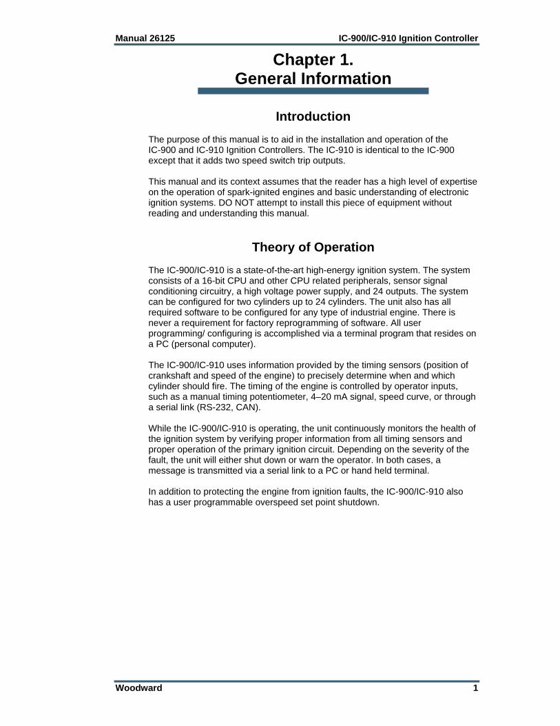
Introduction The purpose of this manual is to aid in the installation and operation of the IC-900 and IC-910 Ignition Controllers. The IC-910 is identical to the IC-900 except that it adds two speed switch trip outputs. This manual and its context assumes that the reader has a high level of expertise on the operation of spark-ignited engines and basic understanding of electronic ignition systems. DO NOT attempt to install this piece of equipment without reading and understanding this manual.
Theory of Operation The IC-900/IC-910 is a state-of-the-art high-energy ignition system. The system consists of a 16-bit CPU and other CPU related peripherals, sensor signal conditioning circuitry, a high voltage power supply, and 24 outputs. The system can be configured for two cylinders up to 24 cylinders. The unit also has all required software to be configured for any type of industrial engine. There is never a requirement for factory reprogramming of software. All user programming/ configuring is accomplished via a terminal program that resides on a PC (personal computer). The IC-900/IC-910 uses information provided by the timing sensors (position of crankshaft and speed of the engine) to precisely determine when and which cylinder should fire. The timing of the engine is controlled by operator inputs, such as a manual timing potentiometer, 4–20 mA signal, speed curve, or through a serial link (RS-232, CAN). While the IC-900/IC-910 is operating, the unit continuously monitors the health of the ignition system by verifying proper information from all timing sensors and proper operation of the primary ignition circuit. Depending on the severity of the fault, the unit will either shut down or warn the operator. In both cases, a message is transmitted via a serial link to a PC or hand held terminal. In addition to protecting the engine from ignition faults, the IC-900/IC-910 also has a user programmable overspeed set point shutdown.

IC-900/IC-910 Ignition Controller Manual 26125
2 Woodward
Electrical Specifications Parameter Min. Max. Comments Supply Voltage 10 V 32 V Permanent damage could occur if
limits are exceeded Current (avg.) 0.1 A 5 A See Note 1. Current (Pk) 25 A See Note 2
Environmental Specifications Temperature –40 to +70 °C (–40 to +158 °F) Humidity 95% RH non-condensing EMC ESD IEC 801-2: Test voltage 8 kV EMI IEC-801-3: Test Frequency 27 to 500 MHz, Field strength
10 V/m IEC 801-4: Test Voltages Aux. Power: 2 kV Digital I/O: 1 kV Analog I/O: 1 kV Interfaces: 1 kV IEC 801-5 Test Voltages Sym. Asym. Aux. Power: 1 kV 2 kV Digital I/O: 0.5 kV 1 kV Analog I/O: 0.5 kV 1 kV Notes 1. Average current is dependent on the number of cylinders, input power,
energy level, and engine speed. 2. Peak current is dependent only on energy level; 100% energy = 25 A pk

Manual 26125 IC-900/IC-910 Ignition Controller
Woodward 3
Figure 1-1. Wiring Diagram—IC-900/IC-910 Timing Sensors

IC-900/IC-910 Ignition Controller Manual 26125
4 Woodward
Figure 1-2. Wiring Diagram—4–20 mA Signal

Manual 26125 IC-900/IC-910 Ignition Controller
Woodward 5
Figure 1-3. Wiring Diagram—IC-900/IC-910 Timing and Safety Controls

IC-900/IC-910 Ignition Controller Manual 26125
6 Woodward
Figure 1-4. Wiring Diagram—16-Cylinder Example

Manual 26125 IC-900/IC-910 Ignition Controller
Woodward 7
Chapter 2. Timing Sensors (MPUs)
Introduction The IC-900/IC-910 requires two timing sensors (magnetic pick-ups/MPUs) for a two-cycle engine and three MPUs for a four-cycle engine.
Trigger MPU The trigger MPU senses teeth or holes in the flywheel or ring gear. The trigger MPU performs two functions: It measures engine speed, and it is used to determine the position of the crankshaft. Type—Normally the MPU is a variable reluctance type (passive), but other types can be used (passive or active). HCI P/N: 9310.0600 (6”) HCI P/N: 9310.0400 (4”) HCI P/N: 9310.0250 (2.5”) Location—The location, relative to TDC (top dead center) of the engine, is not critical. Mounting—The preferred orientation of the sensor is orthogonal (at a right angle) to the circumference of the flywheel/ring gear. In small and mid-size engines there is usually a place on the housing/shroud of the ring gear for a hole to be drilled & tapped (5/8”-18) for the sensor. This is an ideal location. If a mounting bracket is required, it must be designed to be as stiff as possible. A vibrating bracket could cause erroneous signals to be generated by the sensor that will be detected by the IC-900/IC-910. An erroneous signal will cause the IC-900/IC-910 to shut down. Wiring—See Figure 1-1. Air Gap—0.030 to 0.060 inch (0.76 to 1.52 mm) (1/2 to 1 turn).
Reset MPU The reset MPU is used to identify a starting location from which all measurements of the trigger MPU starts. This MPU is used to sense an index marker or event (hole or projection) on the flywheel. Only one event per revolution (360 degrees) is permitted. This marker should be between 20 and 120 degrees advance from TDC. The exact location is not critical, but the actual positions must be programmed into the IC-900/IC-910. Also, the location must be at least 10 degrees more advanced than the most advanced running condition of the engine. Location—The location, relative to TDC of the engine is not critical, but the relationship must be known. The IC-900/IC-910 is designed to use existing MPU arrangements that are used on most modern ignition systems.

IC-900/IC-910 Ignition Controller Manual 26125
8 Woodward
Example: If the engine runs at 22 degrees BTDC (before TDC), then the reset position must be at least 22+10= 32 degrees BTDC. In this example the reset location could be anywhere from 32° to 120° BTDC. Type—Normally the MPU is a variable reluctance type (passive), but other types can be used (passive or active). HCI P/N: same as trigger MPU Mounting—The proper location of the reset MPU is relatively easy if the following steps are followed: 1. Locate where you want to mount the reset MPU, inspect the entire
circumference of the flywheel to ensure that there are no gouges, dents, or barring holes that could be detected by the sensor. Once you are satisfied that the surface is clean, perform the following:
2. Drill a small pilot hole in the flywheel housing where the reset MPU is to be mounted. Drill and tap necessary holes and secure the reset MPU mounting bracket to the engine frame or floor.
3. Manually rotate the engine until the timing mark is aligned with your most advanced running condition.
4. Rotate the engine at least 10 degrees opposite the normal rotation of the engine. Record the sum of number of degrees rotated plus the most advanced timing.
Example: If the most advanced is 22 degrees BTDC and the engine was rotated an additional 10 degrees, record 32 degrees (32=22+10). 5. Now inspect the location of the trigger MPU relative to the teeth or holes it is
sensing. For optimum performance, the trigger MPU should be equally spaced between teeth when the reset MPU is aligned with its target. If this is not the case, manually rotate the engine an additional amount so that the trigger MPU is between two teeth. Then, with the same small drill bit, using the previously drilled pilot hole in the shroud/bracket as a guide, drill into the flywheel. Once the depth of the hole is sufficiently deep to act as a guide, the engine may be rotated to get better access to the flywheel to complete the drilling.
If the surface area is smooth and free of any nicks, burrs, or gouges, then a
hole could be used as the index or target. The hole should be enlarged to 0.5 inch (13 mm) diameter with a depth of at least 3/8 inch (9.5 mm). If the surface is not free of nicks, burrs, and gouges, then the index or target needs to be above the rotating surface of the flywheel. One easy method to do this is to drill tap a hex head bolt (1/4-20, 6 mm or similar). With an additional locking (jam) nut, screw in the bolt. The height of the hex head should be at least 3/4 inch (19 mm) above any nicks, burrs, or gouges. Lock the bolt in place by tightening the jam nut.
6. Now drill and tap the pilot hole for the reset MPU.
Manually rotate the engine one complete revolution to ensure that there is enough clearance between the bolt and any part of the housing, shroud or other mechanical part of the engine.
Wiring—See Figure 1-1. Air Gap—0.045 to 0.090 inch (1.14 to 2.29 mm) (3/4 to 1-1/4 turn).

Manual 26125 IC-900/IC-910 Ignition Controller
Woodward 9
Cam MPU The cam MPU is required only for four-stroke engines. If your engine is two-stroke, skip this section. The cam MPU is used to determine what cycle the engine is on. This MPU must be mounted to sense an event that occurs once per 720 degrees (two revolutions) of engine rotation. Location—The mounting location is relative to the reset MPU location and the cycle of the engine. The cam MPU should be mounted 20 to 50 degrees more advanced than the reset MPU on the compression stroke of the number one cylinder. Air Gap—0.030 to 0.060 inch (0.76 to 1.52 mm) (1/2 to 1 turn). Example: If the engine runs at 22 degrees BTDC, then the reset position must be at least 22+10=32° BTDC. In this example, the reset location could be mounted anywhere from 32 to 120° BTDC. Then the cam MPU should be located 52 to 170° BTDC. Type—Normally the cam MPU is a zero-velocity MPU (active). HCI P/N: 9310.0600 (6”) HCI P/N: 9310.0400 (4”) HCI P/N: 9310.0250 (2.5”) Mounting—Identify a gear or shaft that rotates at cam speed (1/2 engine speed). Choose a location such that the MPU can be mounted at a right angle to the target (hole/bolt). Wiring—See Figure 1-1.
IC-900/IC-910 Ignition Controller Manual 26125
10 Woodward
Chapter 3. Timing Controls
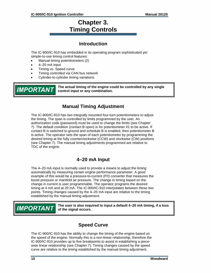
Introduction The IC-900/IC-910 has embedded in its operating program sophisticated yet simple-to-use timing control features: Manual timing potentiometers (2) 4–20 mA input Timing vs. Speed curve Timing controlled via CAN bus network Cylinder-to-cylinder timing variations
The actual timing of the engine could be controlled by any single control input or any combination.
Manual Timing Adjustment The IC-900/IC-910 has two integrally mounted four-turn potentiometers to adjust the timing. The span is controlled by limits programmed by the user. An authorization code (password) must be used to change the limits (see Chapter 7). The default condition (contact B open) is for potentiometer #1 to be active. If contact B is switched to ground and schedule B is enabled, then potentiometer B is active. The operator sets the span of each potentiometer by programming the desired timing at the fully counterclockwise (CCW) and clockwise (CW) positions (see Chapter 7). The manual timing adjustments programmed are relative to TDC of the engine.
4–20 mA Input The 4–20 mA input is normally used to provide a means to adjust the timing automatically by measuring certain engine performance parameter. A good example of this would be a pressure-to-current (P/I) converter that measures the boost pressure or manifold air pressure. The change in timing based on the change in current is user programmable. The operator programs the desired timing at 4 mA and at 20 mA. The IC-900/IC-910 interpolates between these two points. Timing changes caused by the 4–20 mA input are relative to the timing established by the manual timing adjustment.
The user is also required to input a default 4–20 mA timing, if a loss of the signal occurs.
Speed Curve The IC-900/IC-910 has the ability to change the timing of the engine based on the speed of the engine. Normally this is a non-linear relationship, therefore the IC-900/IC-910 provides up to five breakpoints to assist in establishing a piece-wise linear relationship (see Chapter 7). Timing changes caused by the speed curve are relative to the timing established by the manual timing adjustment.

Manual 26125 IC-900/IC-910 Ignition Controller
Woodward 11
Timing Schedules A and B The IC-900/IC-910 also provides the ability to program two different timing schedules: Schedule A and Schedule B. The schedules are selected by a contact closure (Contact B). Pot A is tied to schedule A, and Pot B is tied to schedule B. These schedules could be related to the type of fuel used or for troubleshooting. A good example of the use of the dual timing schedules is applications where two different types of fuel are used (for example, methane and propane). Example: Schedule A timing could consist of: Pot A+4–20 mA+Speed Curve. Schedule B timing could consist of only Pot B.
Cylinder-to-Cylinder Timing Controls The timing of any cylinder can be changed by a fixed amount relative to the Global Timing (pot, 4–20 mA, or speed curve). The primary purpose of this control is to negate any ill effect of manifold design or other factors that generally cause one or two cylinders to be more sensitive to detonations than others. This feature allows the operator to run the engine at a more advanced timing setting than it would normally be able to, by retarding the one or two cylinders that tend to detonate first. To enter the cylinder-to-cylinder timing screen, press “C” from the main screen. The following screen should appear:
Cylinder-to-Cylinder Screen Cylinder-to-Cylinder Timing Procedure—From the cylinder-to-cylinder screen, press F2 until the cylinder that is going to be changed is displayed (remember it is the firing order, NOT the actual cylinder number). Then press F1. Enter the new timing point, press ENTER, then F1 or F2 if it is advanced or retarded. Press F5 when done. Repeat the above process until all the cylinders that need to be changed are done.
All cylinder-to-cylinder timing changes are relative to the global timing established by timing schedules A and B.
CYL #: 1 0.00 ADV (RET) F1: CHANGE F2: NEXT F3: PREVIOUS F5: SAVE

IC-900/IC-910 Ignition Controller Manual 26125
12 Woodward
Chapter 4. High Voltage Supply and Primary Outputs
High Voltage Power Supply The IC-900/IC-910 has two high voltage power supplies that are capable of 300 Vdc. One supply is dedicated to the odd cylinders and the other supply is dedicated to the even cylinders. The energy level control for each power supply is independent of the other. The range of adjustment 100 V (10%) to 300 V (100%). This voltage can be monitored on pin “M” of each primary connector. The signal present on pin “M” is a 10:1 reduction of the actual voltage.
Primary Wiring The IC-900/IC-910 is a negative-ground ignition system. If HCI coils are used, wire the ignition coils using the Connector Pin Assignments chart(s) in this chapter. If existing coils are used, make sure that they are also for a negative ground ignition system. If not the "+" and "–" of the coils will need to be switched.
Odd Bank Connector The connector for the Odd bank of cylinders is a 17-pin connector. The cylinders associated with this connector are 1st cylinder in firing order, 3rd cylinder in firing order, 5th cylinder in firing order, and so forth.
Even Bank Connector The connector for the Even bank of cylinders is a 14-pin connector. The cylinders associated with this connector are 2nd cylinder in firing order, 4th cylinder in firing order, 6th cylinder in firing order, and so forth.
Primary Wire Minimum size: 18 AWG (1 mm²), voltage rating: 600 V.
When replacing an existing ignition system, carefully inspect primary wiring. If the insulation shows any sign of wear or fatigue, the wiring should be replaced.
Manual 26125 IC-900/IC-910 Ignition Controller
Woodward 13
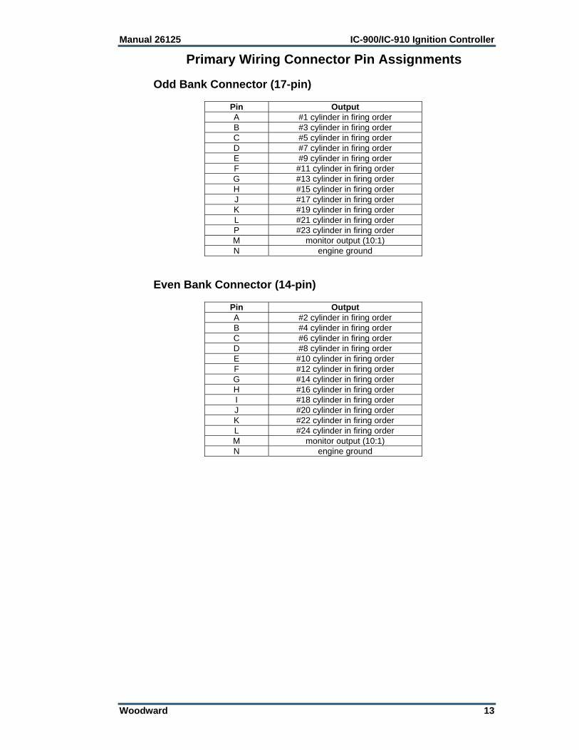
Primary Wiring Connector Pin Assignments Odd Bank Connector (17-pin)
Pin OutputA #1 cylinder in firing order B #3 cylinder in firing order C #5 cylinder in firing order D #7 cylinder in firing order E #9 cylinder in firing order F #11 cylinder in firing order G #13 cylinder in firing order H #15 cylinder in firing order J #17 cylinder in firing order K #19 cylinder in firing order L #21 cylinder in firing order P #23 cylinder in firing order M monitor output (10:1) N engine ground
Even Bank Connector (14-pin)
Pin OutputA #2 cylinder in firing order B #4 cylinder in firing order C #6 cylinder in firing order D #8 cylinder in firing order E #10 cylinder in firing order F #12 cylinder in firing order G #14 cylinder in firing order H #16 cylinder in firing order I #18 cylinder in firing order J #20 cylinder in firing order K #22 cylinder in firing order L #24 cylinder in firing order M monitor output (10:1) N engine ground
IC-900/IC-910 Ignition Controller Manual 26125
14 Woodward
Chapter 5. Energy Control
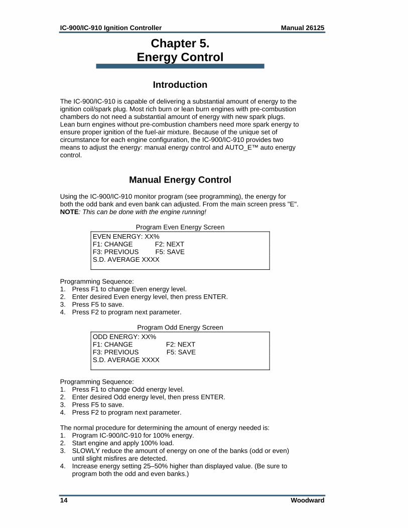
Introduction The IC-900/IC-910 is capable of delivering a substantial amount of energy to the ignition coil/spark plug. Most rich burn or lean burn engines with pre-combustion chambers do not need a substantial amount of energy with new spark plugs. Lean burn engines without pre-combustion chambers need more spark energy to ensure proper ignition of the fuel-air mixture. Because of the unique set of circumstance for each engine configuration, the IC-900/IC-910 provides two means to adjust the energy: manual energy control and AUTO_E™ auto energy control.
Manual Energy Control Using the IC-900/IC-910 monitor program (see programming), the energy for both the odd bank and even bank can adjusted. From the main screen press "E". NOTE: This can be done with the engine running!
Program Even Energy Screen
Programming Sequence: 1. Press F1 to change Even energy level. 2. Enter desired Even energy level, then press ENTER. 3. Press F5 to save. 4. Press F2 to program next parameter.
Program Odd Energy Screen
Programming Sequence: 1. Press F1 to change Odd energy level. 2. Enter desired Odd energy level, then press ENTER. 3. Press F5 to save. 4. Press F2 to program next parameter. The normal procedure for determining the amount of energy needed is: 1. Program IC-900/IC-910 for 100% energy. 2. Start engine and apply 100% load. 3. SLOWLY reduce the amount of energy on one of the banks (odd or even)
until slight misfires are detected. 4. Increase energy setting 25–50% higher than displayed value. (Be sure to
program both the odd and even banks.)
EVEN ENERGY: XX% F1: CHANGE F2: NEXT F3: PREVIOUS F5: SAVE S.D. AVERAGE XXXX
ODD ENERGY: XX% F1: CHANGE F2: NEXT F3: PREVIOUS F5: SAVE S.D. AVERAGE XXXX

Manual 26125 IC-900/IC-910 Ignition Controller
Woodward 15
AUTO_E™ Auto Energy Control The AUTO_E (patent pending) feature of the IC-900/IC-910 allows the energy level to be automatically adjusted based on the spark plug voltage. This feature can be enabled or disabled while the engine is running. The screen that enables/disables the feature can be accessed after Pressing "E" from the main screen and then pressing F2 twice.
Program AUTO_E Enable Screen
Programming Sequence: 1. Press F1 to change enabled/disabled status. 2. Press F1 to enable/disable AUTO_E feature. 3. Press F5 to save. 4. Press F2 to program set point.
Program Energy Setpoint Screen
Programming Sequence: 1. Press F1 change Energy set point. 2. Enter desired Energy set point, then press ENTER (see Set-up procedure). 3. Press F5 to save. 4. Press F2 to program next parameter. AUTO_E Setup Procedure (to be used with new gapped spark plugs) 1. Disable AUTO_E feature and set odd/even manual energy to 100%. 2. Start and load engine (100%). 3. SLOWLY reduce the amount of energy on one of the banks (odd or even)
until slight misfires are detected. 4. Increase energy by an additional 20%. 5. Record displayed “S.D. AVG.” (this will be used later). 6. Reset energy level to 100%. 7. Press “F2” until the Energy Setpoint Screen is displayed. 8. Enter recorded “S.D. AVG.” as the Energy Setpoint (remember F5 to save!). 9. Press “F2” until the AUTO_E Enable Screen is displayed. 10. Enable AUTO_E (remember F5 to save). 11. Press ESC once. The IC-900/IC-910 is now configured for AUTO_E control. If properly programmed, the IC-900/IC-910 should reduce the energy (voltage) delivered to each cylinder until the desired spark duration is achieved. As the load is decreased from 100% load, the IC-900/IC-910 should automatically reduce the energy to the cylinders. As the spark plugs erode, the energy should automatically increase.
AUTO ENERGY ENABLED (disabled) F1: CHANGE F2: NEXT F3: PREVIOUS F5: SAVE
ENERGY SETPOINT: XXXX F1: CHANGE F2: NEXT F3: PREVIOUS F5: SAVE

IC-900/IC-910 Ignition Controller Manual 26125
16 Woodward
Chapter 6. Engine Controls and Safety Features
Introduction The IC-900/IC-910 has built-in features that protect the engine if any malfunction related to the ignition system is detected: Overspeed Protection Permissive Start Output Auxiliary Shutdown Input Misfire Limit Timing Sensor Fault Detection
Overspeed Protection Integral to the IC-900/IC-910 is overspeed protection. The user can program the exact speed at which the ignition should stop (see Chapter 7).
The engine, turbine, or other type of prime mover should be equipped with an overspeed shutdown device to protect against runaway or damage to the prime mover with possible personal injury, loss of life, or property damage. The overspeed shutdown device must be totally independent of the prime mover control system. An overtemperature or overpressure shutdown device may also be needed for safety, as appropriate.
Permissive Start Output Integral to the IC-900/IC-910 is a solid-state output, capable of sinking 250 mA, that should be used to enable/disable fuel flow to the engine directly or in combination with other devices (lube oil pressure, etc.). Anytime the ignition stops due to normal stop sequence, overspeed, or when a fault is detected, the Permissive Start output will de-energize. Upon start-up, the Permissive Start output will not energize until all timing signals are verified correct and the ignition is starting to fire. An LED is also provided as a visual indication of the status of the Permissive Start output (see Chapter 7).
Auxiliary Shutdown Input The IC-900/IC-910 provides a low voltage, low current means of shutting down the ignition system using a PLC or similar device. If Contact A of the control inputs is closed to ground, the ignition outputs will not fire. If the contact is closed above the security speed, it is necessary for the rpm to go to zero before the outputs will fire. If the contact is open below the security speed, the ignition will fire immediately if the trigger, reset, and cam signals are correct.
Manual 26125 IC-900/IC-910 Ignition Controller
Woodward 17
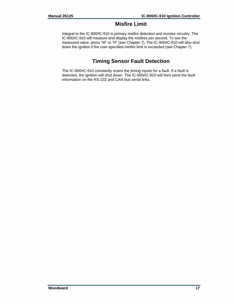
Misfire Limit Integral to the IC-900/IC-910 is primary misfire detection and monitor circuitry. The IC-900/IC-910 will measure and display the misfires per second. To see the measured value, press "M" or “H” (see Chapter 7). The IC-900/IC-910 will also shut down the ignition if the user-specified misfire limit is exceeded (see Chapter 7).
Timing Sensor Fault Detection The IC-900/IC-910 constantly scans the timing inputs for a fault. If a fault is detected, the ignition will shut down. The IC-900/IC-910 will then send the fault information on the RS-232 and CAN bus serial links.

IC-900/IC-910 Ignition Controller Manual 26125
18 Woodward
Chapter 7. Programming
Required Equipment In order to program the IC-900/IC-910, the following items are needed: 12/24 Vdc supply RS-232 cable PC / Laptop or hand held terminal IC-900/IC-910 monitor program (free, contact your local distributor or
factory) The Appendix contains a Programming Flowchart and a Configuration Form which should be filled out and kept in a secure place for future reference.
Definitions and Programming Parameters Number of Cylinders—Actual number of cylinders, or in some applications
where there are two spark plugs with an offset, the number of spark plugs used. Must be correct for the sequence number programmed. Range: 1–24.
Number of Teeth—Number of teeth in the ring gear or holes in the flywheel that the trigger MPU senses per one revolution of the engine. Range: 60–500.
Sequence Number—A number that is related to the firing interval of the engine. Use the engine specifications and the Timing Sequence tables in the Appendix to determine the correct sequence number. Must be correct for the number of cylinders programmed.
Reset Position—The location of the reset MPU relative to TDC of cylinder 1.
Overspeed—The rpm at which the ignition should shut down if exceeded. Security Speed—The speed that controls the operation of Contact A.
Contact A enables or disables the primary outputs. The Security Speed determines whether the engine speed must go to zero after Contact A is closed (to ground), or if the primary outputs can be enabled during cranking. If the speed goes above the security speed with Contact A closed, it is necessary to wait for 0 rpm before the primary outputs will be enabled. If the speed stays below the security speed, and Contact A goes from closed to open, the primary outputs will be enabled and the ignition will start firing.
Misfire Rate—The number of misses per second that is permissible before the engine shuts down due to misfire rate exceeded. To disable, set misfire rate to zero.
CAN_ID—Used only for CAN communication. CAN (Enable/Disable)—Used to enable/disable CAN communications.
Should be disabled if CAN communication is not used. Schedule B (Enable/Disable)—Second timing schedule, activated with
external contact (switch) to ground. This feature can be enabled or disabled during programming.
Speed Curve in A (Enable/Disable)—Include/exclude the speed curve as part of Schedule A timing scheme.
4-20 mA Timing In A (Enable/Disable)—Include/exclude 4–20 mA signal as part of Schedule A timing scheme.
Speed Curve In B (Enable/Disable)—Include/exclude speed curve as part of Schedule B timing scheme.

Manual 26125 IC-900/IC-910 Ignition Controller
Woodward 19
4-20 mA Timing In B (Enable/Disable)—Include/exclude 4–20 mA signal as part of Schedule B timing scheme.
POT A CCW—Timing relative to TDC, of Pot A when fully CCW. POT A CW—Timing relative to TDC, of Pot A when fully CW. Schedule A Max. Advance—The maximum allowable advance,
independent of any timing variable (Pot A, 4–20 mA and Speed Curve). Schedule A Max. Retard—The maximum allowable retard, independent of
any timing variable (Pot A, 4–20 mA and Speed Curve). POT B CCW—Timing relative to TDC, of Pot B when fully CCW. POT B CW—Timing relative to TDC, of Pot B when fully CW. Schedule B Max. Advance—The maximum allowable advance,
independent of any timing variable (Pot A, 4–20 mA and Speed Curve). Schedule B Max. Retard—The maximum allowable retard, independent of
any timing variable (Pot B, 4–20 mA and Speed Curve). 4–20mA Timing at 4mA—Desired timing response to a 4 mA signal relative
to the timing established by Pot A (Pot B). 4–20mA Timing at 20mA—Desired timing response to a 20 mA signal
relative to the timing established by Pot A (Pot B). Dflt 4-20mA Timing—Desired timing response if loss of signal is detected. Speed Curve-Number of Breakpoints—The number of line segments that
make up the timing response to engine speed. Range: 1–5. Breakpoint “n” RPM—Engine speed of “n” breakpoint; “n”=1 to 5. Breakpoint “n” Timing—Desired timing at breakpoint “n” relative to the
timing established by Pot A (Pot B).
Speed Switches (IC-910) The IC-910 provides two speed outputs, called “Trip 1” and “Trip 2”. The trip point of each output is adjustable from 0 to 5000 rpm. Each output also has a separately adjustable “hysteresis” trip point, with a range from 0 to 5000 rpm. The speed switch is activated when engine speed exceeds the “trip” point, and the speed switch is reset when engine speed goes below the trip point minus the “hysteresis” value. If the hysteresis value is greater or equal to the trip speed value, the output is reset again at 0 rpm. If the trip point is set with a positive value (0 to 5000), the switch output will be normally closed, and open when the trip point is exceeded. If the trip point is set with a negative value (–1 to –5000), the switch output will be normally open, and close when the trip point is exceeded.
Configuration Programming Procedure Connect your PC to the IC-900/IC-910 via the RS-232 cable.
The IC-900/IC-910 has two DB9 connectors. Identify and use the one marked “RS-232”.
IC-900/IC-910 Ignition Controller Manual 26125
20 Woodward
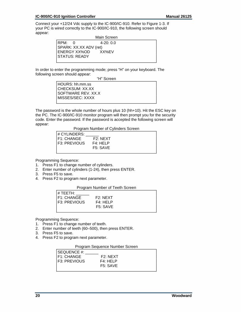
Connect your +12/24 Vdc supply to the IC-900/IC-910. Refer to Figure 1-3. If your PC is wired correctly to the IC-900/IC-910, the following screen should appear:
Main Screen
In order to enter the programming mode; press “H” on your keyboard. The following screen should appear:
“H” Screen
The password is the whole number of hours plus 10 (hh+10). Hit the ESC key on the PC. The IC-900/IC-910 monitor program will then prompt you for the security code. Enter the password. If the password is accepted the following screen will appear:
Program Number of Cylinders Screen
Programming Sequence: 1. Press F1 to change number of cylinders. 2. Enter number of cylinders (1-24), then press ENTER. 3. Press F5 to save. 4. Press F2 to program next parameter.
Program Number of Teeth Screen
Programming Sequence: 1. Press F1 to change number of teeth. 2. Enter number of teeth (60–500), then press ENTER. 3. Press F5 to save. 4. Press F2 to program next parameter.
Program Sequence Number Screen
RPM: 0 4-20: 0.0 SPARK: XX.XX ADV (ret) ENERGY XX%OD XX%EV STATUS: READY
HOURS: hh.mm.ss CHECKSUM: XX.XX SOFTWARE REV. XX.X MISSES/SEC: XXXX
# CYLINDERS: ______ F1: CHANGE F2: NEXT F3: PREVIOUS F4: HELP F5: SAVE
# TEETH: ______ F1: CHANGE F2: NEXT F3: PREVIOUS F4: HELP F5: SAVE
SEQUENCE #: ______ F1: CHANGE F2: NEXT F3: PREVIOUS F4: HELP F5: SAVE

Manual 26125 IC-900/IC-910 Ignition Controller
Woodward 21
Programming Sequence: 1. Press F1 to change sequence number. 2. Enter sequence number (1–168), then press ENTER.
Always refer to the engine specification and the Timing Sequence tables in the Appendix before entering data. Failure to enter proper sequence number could cause personal injury or equipment damage.
3. Press F5 to save. 4. Press F2 to program next parameter.
Program Reset Position Screen
Programming Sequence: 1. Press F1 to change reset MPU position. 2. Enter reset position (10* to 120 Advance), then press ENTER. 3. Press F5 to save. 4. Press F2 to program next parameter. * NOTE—Minimum reset position is 10 degrees + most advanced timing of the engine.
Program Overspeed Trip Point Screen
Programming Sequence: 1. Press F1 to change overspeed trip point. 2. Enter overspeed trip point, then press ENTER. 3. Press F5 to save. Press F2 to program next parameter.
Program Security Speed Screen
Programming Sequence: 1. Press F1 to change security speed. 2. Enter security speed, then press ENTER. 3. Press F5 to save. 4. Press F2 to program next parameter.
RESET POSITION: ______ F1: CHANGE F2: NEXT F3: PREVIOUS F4: HELP F5: SAVE
OVERSPEED: ________ F1: CHANGE F2: NEXT F3: PREVIOUS F4: HELP F5: SAVE
SECURITY SPEED: ___________ F1: CHANGE F2: NEXT F3: PREVIOUS F4: HELP F5: SAVE

IC-900/IC-910 Ignition Controller Manual 26125
22 Woodward
Program Misfire Rate Screen
Programming Sequence: 1. Press F1 to change misfire rate trip point. 2. Enter misfire rate trip point, then press ENTER. 3. Press F5 to save. 4. Press F2 to program next parameter.
Program Speed Trigger 1 Screen
Programming Sequence (NOTE that this feature is found in the IC-910 only): 1. Press F1 to change speed trigger 1 trip point. 2. Enter speed trigger 1 rpm, then press ENTER. 3. Press F5 to save. 4. Press F2 to program next parameter.
Program Hysteresis 1 Screen
Programming Sequence (NOTE that this feature is found in the IC-910 only): 1. Press F1 to change speed trigger hysteresis 1 trip point. 2. Enter hysteresis 1 rpm, then press ENTER. 3. Press F5 to save. 4. Press F2 to program next parameter.
Program Speed Trigger 2 Screen
Programming Sequence (NOTE that this feature is found in the IC-910 only): 1. Press F1 to change speed trigger 2 trip point. 2. Enter speed trigger 2 rpm, then press ENTER. 3. Press F5 to save. 4. Press F2 to program next parameter.
MIS-FIRE LIMIT: _______ F1: CHANGE F2: NEXT F3: PREVIOUS F4: HELP F5: SAVE
TRIP 1: _____ F1: CHANGE F2: NEXT F3: PREVIOUS F4: HELP F5: SAVE
HYSTERESIS 1: _____ F1: CHANGE F2: NEXT F3: PREVIOUS F4: HELP F5: SAVE
TRIP 2: _____ F1: CHANGE F2: NEXT F3: PREVIOUS F4: HELP F5: SAVE

Manual 26125 IC-900/IC-910 Ignition Controller
Woodward 23
Program Hysteresis 2 Screen
Programming Sequence (NOTE that this feature is found in the IC-910 only): 1. Press F1 to change speed trigger hysteresis 2 trip point. 2. Enter hysteresis 2 rpm, then press ENTER. 3. Press F5 to save. 4. Press F2 to program next parameter.
Program CAN_ID Screen
Programming Sequence: 1. Press F1 to change CAN_ID address. 2. Enter CAN_ID address, then press ENTER. 3. Press F5 to save. 4. Press F2 to program next parameter.
Program CAN Enable Screen
Programming Sequence: 1. Press F1 to change, then 2. Press F1 to Enable CAN Communication OR 3. Press F2 to Disable CAN Communication. 4. Press F5 to save. 5. Press F2 to program next parameter.
Program Schedule B Enable Screen
Programming Sequence: 1. Press F1 to change, then 2. Press F1 to Enable Schedule B OR 3. Press F2 to Disable Schedule B. 4. Press F5 to save. 5. Press F2 to program next parameter.
HYSTERESIS 2: _____ F1: CHANGE F2: NEXT F3: PREVIOUS F4: HELP F5: SAVE
CAN_ID: _____ F1: CHANGE F2: NEXT F3: PREVIOUS F4: HELP F5: SAVE
CAN ENABLE (disable) F1: CHANGE F2: NEXT F3: PREVIOUS F4: HELP F5: SAVE
SCHEDULE B: ENABLE (disable) F1: CHANGE F2: NEXT F3: PREVIOUS F4: HELP F5: SAVE
IC-900/IC-910 Ignition Controller Manual 26125
24 Woodward
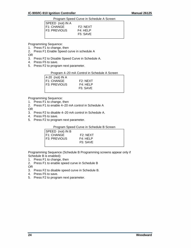
Program Speed Curve in Schedule A Screen
Programming Sequence: 1. Press F1 to change, then 2. Press F1 Enable Speed curve in schedule A OR 3. Press F2 to Disable Speed Curve in Schedule A. 4. Press F5 to save. 5. Press F2 to program next parameter.
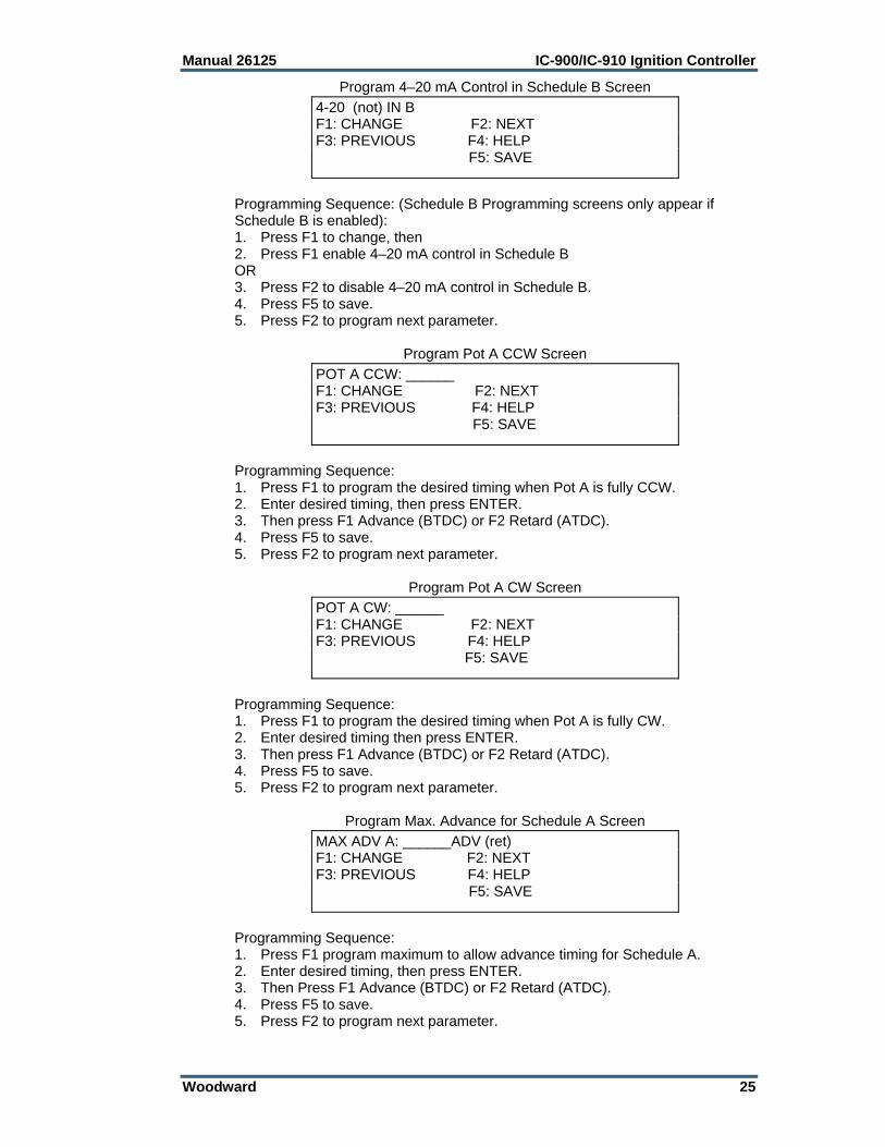
Program 4–20 mA Control in Schedule A Screen
Programming Sequence: 1. Press F1 to change, then 2. Press F1 to enable 4–20 mA control in Schedule A OR 3. Press F2 to disable 4–20 mA control in Schedule A. 4. Press F5 to save. 5. Press F2 to program next parameter.
Program Speed Curve in Schedule B Screen
Programming Sequence (Schedule B Programming screens appear only if Schedule B is enabled): 1. Press F1 to change, then 2. Press F1 to enable speed curve in Schedule B OR 3. Press F2 to disable speed curve in Schedule B. 4. Press F5 to save. 5. Press F2 to program next parameter.
SPEED (not) IN A F1: CHANGE F2: NEXT F3: PREVIOUS F4: HELP F5: SAVE
4-20 (not) IN A F1: CHANGE F2: NEXT F3: PREVIOUS F4: HELP F5: SAVE
SPEED (not) IN B F1: CHANGE F2: NEXT F3: PREVIOUS F4: HELP F5: SAVE
Manual 26125 IC-900/IC-910 Ignition Controller
Woodward 25
Program 4–20 mA Control in Schedule B Screen
Programming Sequence: (Schedule B Programming screens only appear if Schedule B is enabled): 1. Press F1 to change, then 2. Press F1 enable 4–20 mA control in Schedule B OR 3. Press F2 to disable 4–20 mA control in Schedule B. 4. Press F5 to save. 5. Press F2 to program next parameter.
Program Pot A CCW Screen
Programming Sequence: 1. Press F1 to program the desired timing when Pot A is fully CCW. 2. Enter desired timing, then press ENTER. 3. Then press F1 Advance (BTDC) or F2 Retard (ATDC). 4. Press F5 to save. 5. Press F2 to program next parameter.
Program Pot A CW Screen
Programming Sequence: 1. Press F1 to program the desired timing when Pot A is fully CW. 2. Enter desired timing then press ENTER. 3. Then press F1 Advance (BTDC) or F2 Retard (ATDC). 4. Press F5 to save. 5. Press F2 to program next parameter.
Program Max. Advance for Schedule A Screen
Programming Sequence: 1. Press F1 program maximum to allow advance timing for Schedule A. 2. Enter desired timing, then press ENTER. 3. Then Press F1 Advance (BTDC) or F2 Retard (ATDC). 4. Press F5 to save. 5. Press F2 to program next parameter.
4-20 (not) IN B F1: CHANGE F2: NEXT F3: PREVIOUS F4: HELP F5: SAVE
POT A CCW: ______ F1: CHANGE F2: NEXT F3: PREVIOUS F4: HELP F5: SAVE
POT A CW: ______ F1: CHANGE F2: NEXT F3: PREVIOUS F4: HELP F5: SAVE
MAX ADV A: ______ADV (ret) F1: CHANGE F2: NEXT F3: PREVIOUS F4: HELP F5: SAVE
IC-900/IC-910 Ignition Controller Manual 26125
26 Woodward
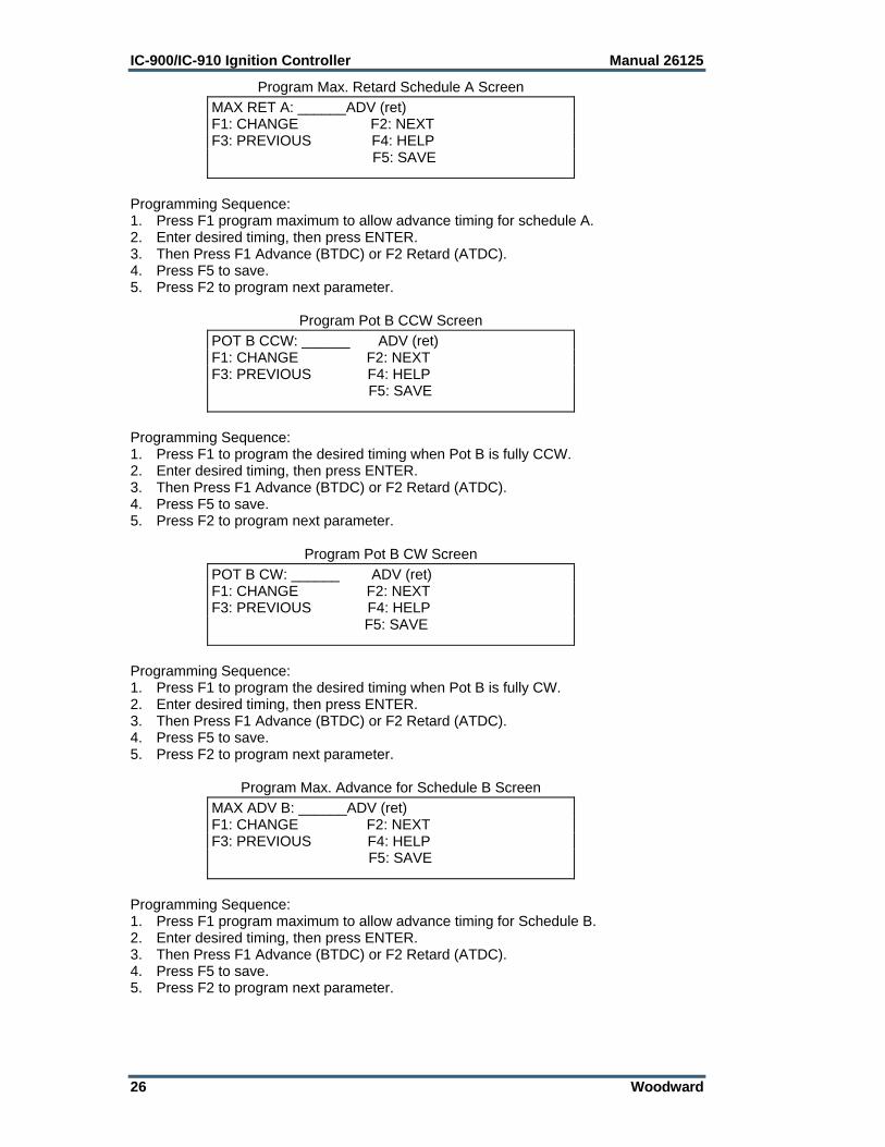
Program Max. Retard Schedule A Screen
Programming Sequence: 1. Press F1 program maximum to allow advance timing for schedule A. 2. Enter desired timing, then press ENTER. 3. Then Press F1 Advance (BTDC) or F2 Retard (ATDC). 4. Press F5 to save. 5. Press F2 to program next parameter.
Program Pot B CCW Screen
Programming Sequence: 1. Press F1 to program the desired timing when Pot B is fully CCW. 2. Enter desired timing, then press ENTER. 3. Then Press F1 Advance (BTDC) or F2 Retard (ATDC). 4. Press F5 to save. 5. Press F2 to program next parameter.
Program Pot B CW Screen
Programming Sequence: 1. Press F1 to program the desired timing when Pot B is fully CW. 2. Enter desired timing, then press ENTER. 3. Then Press F1 Advance (BTDC) or F2 Retard (ATDC). 4. Press F5 to save. 5. Press F2 to program next parameter.
Program Max. Advance for Schedule B Screen
Programming Sequence: 1. Press F1 program maximum to allow advance timing for Schedule B. 2. Enter desired timing, then press ENTER. 3. Then Press F1 Advance (BTDC) or F2 Retard (ATDC). 4. Press F5 to save. 5. Press F2 to program next parameter.
MAX RET A: ______ADV (ret) F1: CHANGE F2: NEXT F3: PREVIOUS F4: HELP F5: SAVE
POT B CCW: ______ ADV (ret) F1: CHANGE F2: NEXT F3: PREVIOUS F4: HELP F5: SAVE
POT B CW: ______ ADV (ret) F1: CHANGE F2: NEXT F3: PREVIOUS F4: HELP F5: SAVE
MAX ADV B: ______ADV (ret) F1: CHANGE F2: NEXT F3: PREVIOUS F4: HELP F5: SAVE
Manual 26125 IC-900/IC-910 Ignition Controller
Woodward 27
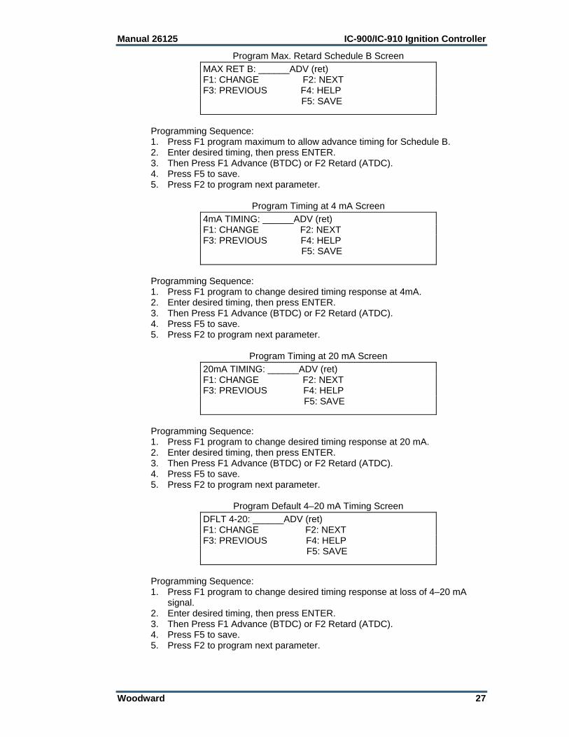
Program Max. Retard Schedule B Screen
Programming Sequence: 1. Press F1 program maximum to allow advance timing for Schedule B. 2. Enter desired timing, then press ENTER. 3. Then Press F1 Advance (BTDC) or F2 Retard (ATDC). 4. Press F5 to save. 5. Press F2 to program next parameter.
Program Timing at 4 mA Screen
Programming Sequence: 1. Press F1 program to change desired timing response at 4mA. 2. Enter desired timing, then press ENTER. 3. Then Press F1 Advance (BTDC) or F2 Retard (ATDC). 4. Press F5 to save. 5. Press F2 to program next parameter.
Program Timing at 20 mA Screen
Programming Sequence: 1. Press F1 program to change desired timing response at 20 mA. 2. Enter desired timing, then press ENTER. 3. Then Press F1 Advance (BTDC) or F2 Retard (ATDC). 4. Press F5 to save. 5. Press F2 to program next parameter.
Program Default 4–20 mA Timing Screen
Programming Sequence: 1. Press F1 program to change desired timing response at loss of 4–20 mA
signal. 2. Enter desired timing, then press ENTER. 3. Then Press F1 Advance (BTDC) or F2 Retard (ATDC). 4. Press F5 to save. 5. Press F2 to program next parameter.
MAX RET B: ______ADV (ret) F1: CHANGE F2: NEXT F3: PREVIOUS F4: HELP F5: SAVE
4mA TIMING: ______ADV (ret) F1: CHANGE F2: NEXT F3: PREVIOUS F4: HELP F5: SAVE
20mA TIMING: ______ADV (ret) F1: CHANGE F2: NEXT F3: PREVIOUS F4: HELP F5: SAVE
DFLT 4-20: ______ADV (ret) F1: CHANGE F2: NEXT F3: PREVIOUS F4: HELP F5: SAVE
IC-900/IC-910 Ignition Controller Manual 26125
28 Woodward
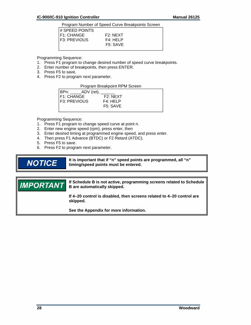
Program Number of Speed Curve Breakpoints Screen
Programming Sequence: 1. Press F1 program to change desired number of speed curve breakpoints. 2. Enter number of breakpoints, then press ENTER. 3. Press F5 to save. 4. Press F2 to program next parameter.
Program Breakpoint RPM Screen
Programming Sequence: 1. Press F1 program to change speed curve at point n. 2. Enter new engine speed (rpm), press enter, then 3. Enter desired timing at programmed engine speed, and press enter. 4. Then press F1 Advance (BTDC) or F2 Retard (ATDC). 5. Press F5 to save. 6. Press F2 to program next parameter.
It is important that if “n” speed points are programmed, all “n” timing/speed points must be entered.
If Schedule B is not active, programming screens related to Schedule B are automatically skipped. If 4–20 control is disabled, then screens related to 4–20 control are skipped. See the Appendix for more information.
# SPEED POINTS F1: CHANGE F2: NEXT F3: PREVIOUS F4: HELP F5: SAVE
BPn: _____ADV (ret), ______ F1: CHANGE F2: NEXT F3: PREVIOUS F4: HELP F5: SAVE
Manual 26125 IC-900/IC-910 Ignition Controller
Woodward 29
Chapter 8. Start-up Procedure
I. Before applying power to the IC-900/IC-910, check and verify the following: 1. Fuel valve is shut off. 2. The firing interval (sequence number) is correct for the engine type. If you
are not sure, contact your engine manufacturer. 3. Cylinder firing order is known and the ignition coils are wired in accordance
with the Connector Pin Assignments chart(s) in Chapter 4. 4. All timing sensors are properly gapped and tightened. 5. All timing sensors are wired in accordance with Figure 1-1. II. Apply power to the IC-900/IC-910 (fuel valve still in the off position): 1. Check and verify that the IC-900/IC-910 is programmed correctly (see
Chapter 7). 2. Perform the normal engine start-up procedure (prelube, etc.), except that the
fuel must remain OFF. 3. With a timing light connected to the #1 cylinder, verify that the cylinder is
firing within ±2 degrees of the programmed setting. If not, refer to Chapter 9. 4. Check all remaining cylinders for proper timing. If not correct, stop the engine
and recheck wiring and sequence number for correctness. 5. Disengage the starter. Continue with step III if no problems are encountered. III. Set the fuel valve to its normal position and re-start the engine. 1. If the engine fails to start, refer to Chapter 9. 2. If the engine starts, verify timing of #1 cylinder. 3. Increase engine speed to normal operating speed. 4. Check timing of #1 cylinder and compare measured timing to the displayed
timing (PC/laptop with IC-900/IC-910 monitor program or hand held terminal is required).
5. If the IC-900/IC-910 is measuring too high, the reset position needs to be reduced by the difference.
Example: If the IC-900/IC-910 monitor is displaying 22.0 Adv. and the measured timing is 20.5 Adv., the reset position will have to be reduced by 1.5 degrees (22–20.5). If the reset position is 50 Adv., the reset position will have to be changed to 48.5 degrees. 6. If the IC-900/IC-910 is measuring too low, the reset position will have to be
increased by the difference. 7. Shut down the engine using the normal shutdown procedure and make any
reset position changes required (see Chapter 7). 8. Re-start the engine and verify that the #1 cylinder is firing at the correct
position. 9. Check all remaining cylinders for proper timing. If not correct, stop the engine
and recheck wiring and sequence number for correctness. 10. If all cylinders are operating properly, gradually apply full load to the engine. 11. Verify that all cylinders are still operating properly and that all are carrying the
load. If not refer to Chapter 9. 12. Installation is complete. Save the IC-900/IC-910 Configuration Form (in the
Appendix) for future reference in a secure location.
IC-900/IC-910 Ignition Controller Manual 26125
30 Woodward
Chapter 9. Troubleshooting
Sensor Input Faults TRIGGER MPU—The IC-900/IC-910 measured the number of teeth/events
between two successive reset MPU signals. If the IC-900/IC-910 detects that the programmed number of teeth do not match the measured number of teeth, an error will be detected. Two type of faults exist: 1. WRONG NUMBER OF TEETH PROGRAMMED—This error occurs if the
IC-900/IC-910 never detects the correct number of programmed teeth. Corrective action: 1) Verify tooth count and program in correct number of teeth. 2) Inspect flywheel/ring gear for gouges or other deformities that might generate a signal from the trigger MPU or reset MPU.
2. “RING GEAR MPU ERROR”—Once the engine is running and if an erroneous tooth count is detected, a missing ring gear message will appear. Corrective action: Inspect flywheel/ring gear for gouges or other deformities that might generate a signal from the trigger MPU or reset MPU.
RESET MPU—The IC-900/IC-910 measured the number of events between two successive reset cam signals. If the IC-900/IC-910 detects that the number of events does not match the expected number of events, an error will be detected.
CAM MPU (4 cycle only)—The IC-900/IC-910 measured the number of events between three successive reset MPU signals. If the IC-900/IC-910 detects that the number of events does not match the expected number of events, an error will be detected.
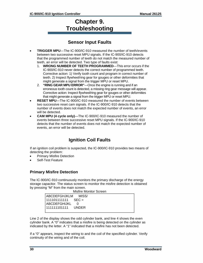
Ignition Coil Faults If an ignition coil problem is suspected, the IC-900/IC-910 provides two means of detecting the problem: Primary Misfire Detection Self-Test Feature Primary Misfire Detection The IC-900/IC-910 continuously monitors the primary discharge of the energy storage capacitor. The status screen to monitor the misfire detection is obtained by pressing “M” from the main screen.
Misfire Monitor Screen
Line 2 of the display shows the odd cylinder bank, and line 4 shows the even cylinder bank. A “0” indicates that a misfire is being detected on the cylinder as indicated by the letter. A “1” indicated that a misfire has not been detected. If a “0” appears, inspect the wiring to and the coil of the specified cylinder. Verify continuity of the wiring and of the coil.
ABCDEFGHJKLM MISS/ 111101111111 SEC = ABCDEFGHIJKL 0 111111101111 UNDER
Manual 26125 IC-900/IC-910 Ignition Controller
Woodward 31
Self-Test Feature
In using the self-test feature of the IC-900/IC-910, it is critical that the fuel to the engine must be shut off and the engine purged of any fuel gas before starting the self-test. Failure to do this could result in personal injury or damage to equipment.
The self-test feature of the IC-900/IC-910 allows the operator/mechanic to conduct performance checks on the wiring to the coil, the ignition coil, high tension leads, and spark plugs by discharging the energy stored in the high voltage capacitor into each coil in successive order. The IC-900/IC-910 will “fire” a cylinder every 0.1.second. The energy delivered to each coil is determined by the manual energy level setting. The self-test feature can be started by pressing “S” (upper case) from the main screen. While in self-test, proper performance of each cylinder can be checked using standard troubleshooting tools (timing light, voltmeter, etc.).

IC-900/IC-910 Ignition Controller Manual 26125
32 Woodward
Chapter 10. Product Support and Service Options
Product Support Options If you are experiencing problems with the installation, or unsatisfactory performance of a Woodward product, the following options are available: 1. Consult the troubleshooting guide in the manual. 2. Contact the OE Manufacturer or Packager of your system. 3. Contact the Woodward Business Partner serving your area. 4. Contact Woodward technical assistance via email
([email protected]) with detailed information on the product, application, and symptoms. Your email will be forwarded to an appropriate expert on the product and application to respond by telephone or return email.
5. If the issue cannot be resolved, you can select a further course of action to pursue based on the available services listed in this chapter.
OEM or Packager Support: Many Woodward controls and control devices are installed into the equipment system and programmed by an Original Equipment Manufacturer (OEM) or Equipment Packager at their factory. In some cases, the programming is password-protected by the OEM or packager, and they are the best source for product service and support. Warranty service for Woodward products shipped with an equipment system should also be handled through the OEM or Packager. Please review your equipment system documentation for details. Woodward Business Partner Support: Woodward works with and supports a global network of independent business partners whose mission is to serve the users of Woodward controls, as described here:
A Full-Service Distributor has the primary responsibility for sales, service, system integration solutions, technical desk support, and aftermarket marketing of standard Woodward products within a specific geographic area and market segment.
An Authorized Independent Service Facility (AISF) provides authorized service that includes repairs, repair parts, and warranty service on Woodward's behalf. Service (not new unit sales) is an AISF's primary mission.
A Recognized Engine Retrofitter (RER) is an independent company that does retrofits and upgrades on reciprocating gas engines and dual-fuel conversions, and can provide the full line of Woodward systems and components for the retrofits and overhauls, emission compliance upgrades, long term service contracts, emergency repairs, etc.
A current list of Woodward Business Partners is available at www.woodward.com/directory.
Product Service Options Depending on the type of product, the following options for servicing Woodward products may be available through your local Full-Service Distributor or the OEM or Packager of the equipment system. Replacement/Exchange (24-hour service) Flat Rate Repair Flat Rate Remanufacture
Manual 26125 IC-900/IC-910 Ignition Controller
Woodward 33
Replacement/Exchange: Replacement/Exchange is a premium program designed for the user who is in need of immediate service. It allows you to request and receive a like-new replacement unit in minimum time (usually within 24 hours of the request), providing a suitable unit is available at the time of the request, thereby minimizing costly downtime. This option allows you to call your Full-Service Distributor in the event of an unexpected outage, or in advance of a scheduled outage, to request a replacement control unit. If the unit is available at the time of the call, it can usually be shipped out within 24 hours. You replace your field control unit with the like-new replacement and return the field unit to the Full-Service Distributor. Flat Rate Repair: Flat Rate Repair is available for many of the standard mechanical products and some of the electronic products in the field. This program offers you repair service for your products with the advantage of knowing in advance what the cost will be. Flat Rate Remanufacture: Flat Rate Remanufacture is very similar to the Flat Rate Repair option, with the exception that the unit will be returned to you in “like-new” condition. This option is applicable to mechanical products only.
Returning Equipment for Repair If a control (or any part of an electronic control) is to be returned for repair, please contact your Full-Service Distributor in advance to obtain Return Authorization and shipping instructions. When shipping the item(s), attach a tag with the following information: return number; name and location where the control is installed; name and phone number of contact person; complete Woodward part number(s) and serial number(s); description of the problem; instructions describing the desired type of repair.
Packing a Control Use the following materials when returning a complete control: protective caps on any connectors; antistatic protective bags on all electronic modules; packing materials that will not damage the surface of the unit; at least 100 mm (4 inches) of tightly packed, industry-approved packing
material; a packing carton with double walls; a strong tape around the outside of the carton for increased strength.
To prevent damage to electronic components caused by improper handling, read and observe the precautions in Woodward manual 82715, Guide for Handling and Protection of Electronic Controls, Printed Circuit Boards, and Modules.
Replacement Parts When ordering replacement parts for controls, include the following information: the part number(s) (XXXX-XXXX) that is on the enclosure nameplate; the unit serial number, which is also on the nameplate.

IC-900/IC-910 Ignition Controller Manual 26125
34 Woodward
Engineering Services Woodward’s Full-Service Distributors offer various Engineering Services for our products. For these services, you can contact the Distributor by telephone or by email. Technical Support Product Training Field Service Technical Support is available from your equipment system supplier, your local Full-Service Distributor, or from many of Woodward’s worldwide locations, depending upon the product and application. This service can assist you with technical questions or problem solving during the normal business hours of the Woodward location you contact. Product Training is available as standard classes at many Distributor locations. Customized classes are also available, which can be tailored to your needs and held at one of our Distributor locations or at your site. This training, conducted by experienced personnel, will assure that you will be able to maintain system reliability and availability. Field Service engineering on-site support is available, depending on the product and location, from one of our Full-Service Distributors. The field engineers are experienced both on Woodward products as well as on much of the non-Woodward equipment with which our products interface. For information on these services, please contact one of the Full-Service Distributors listed at www.woodward.com/directory.
Contacting Woodward’s Support Organization For the name of your nearest Woodward Full-Service Distributor or service facility, please consult our worldwide directory published at www.woodward.com/directory. You can also contact the Woodward Customer Service Department at one of the following Woodward facilities to obtain the address and phone number of the nearest facility at which you can obtain information and service.
Products Used In Electrical Power Systems
Facility ---------------- Phone Number Brazil ------------- +55 (19) 3708 4800 China ----------- +86 (512) 6762 6727 Germany: Kempen ---- +49 (0) 21 52 14 51 Stuttgart -- +49 (711) 78954-510 India --------------- +91 (129) 4097100 Japan -------------- +81 (43) 213-2191 Korea -------------- +82 (51) 636-7080 Poland --------------- +48 12 295 13 00 United States ---- +1 (970) 482-5811
Products Used In Engine Systems
Facility ---------------- Phone Number Brazil ------------- +55 (19) 3708 4800 China ----------- +86 (512) 6762 6727 Germany ------- +49 (711) 78954-510 India --------------- +91 (129) 4097100 Japan -------------- +81 (43) 213-2191 Korea -------------- +82 (51) 636-7080 The Netherlands - +31 (23) 5661111 United States ---- +1 (970) 482-5811
Products Used In Industrial Turbomachinery
Systems Facility ---------------- Phone Number Brazil ------------- +55 (19) 3708 4800 China ----------- +86 (512) 6762 6727 India --------------- +91 (129) 4097100 Japan -------------- +81 (43) 213-2191 Korea -------------- +82 (51) 636-7080 The Netherlands - +31 (23) 5661111 Poland --------------- +48 12 295 13 00 United States ---- +1 (970) 482-5811
For the most current product support and contact information, please visit our website directory at www.woodward.com/directory.

Manual 26125 IC-900/IC-910 Ignition Controller
Woodward 35
Technical Assistance
If you need to contact technical assistance, you will need to provide the following information. Please write it down here before contacting the Engine OEM, the Packager, a Woodward Business Partner, or the Woodward factory:
General
Your Name
Site Location
Phone Number
Fax Number
Prime Mover Information
Manufacturer
Engine Model Number
Number of Cylinders
Type of Fuel (gas, gaseous, diesel, dual-fuel, etc.)
Power Output Rating
Application (power generation, marine, etc.)
Control/Governor Information
Control/Governor #1
Woodward Part Number & Rev. Letter
Control Description or Governor Type
Serial Number
Control/Governor #2
Woodward Part Number & Rev. Letter
Control Description or Governor Type
Serial Number
Control/Governor #3
Woodward Part Number & Rev. Letter
Control Description or Governor Type
Serial Number
Symptoms
Description
If you have an electronic or programmable control, please have the adjustment setting positions or the menu settings written down and with you at the time of the call.

IC-900/IC-910 Ignition Controller Manual 26125
36 Woodward
Appendix. Reference Information
Timing Sequence Tables 2-Cycle No. of Cylinders
(2 CYCLE) Sequence Number Firing Interval
1 11 360 - 360
1 97 180 - 540
1 98 540 - 180
2 10 180 - 180
2 81 180 - 240 - 180 - 120
2 82 180 - 90 - 180 - 270
3 1 120 - 120
3 37 90 - 150
3 38 150 - 90
3 51 60 - 180
3 52 180 - 60
3 53 75 - 165
3 54 165 - 75
3 55 55 - 185
3 56 185 - 55
3 79 60 - 180
3 80 180 - 60
3 85 60 - 180 - 120 - 60 - 120 - 180
4 2 90 - 90
4 25 60 - 120
4 26 120 - 60
4 61 45 - 135
4 62 135 - 45
4 67 63 - 117
4 68 117 - 63
4 86 90 - 90 - 90 - 60 - 90 - 90 - 90 - 120
4 87 90 - 90 - 90 - 135 - 90 - 90 - 90 - 45
4 88 90 - 90 - 90 - 65 - 90 - 90 - 90 - 115
4 89 90 - 135 - 45 - 135 - 90 - 45 - 135 - 45
4 137 10 - 170
4 138 170 - 10
4 143 47 - 133 - 47 - 139 - 47 - 133 - 47 - 127
5 3 72 - 72
5 69 27 - 117
5 70 117 - 27
5 73 12 - 132
5 74 132 - 12
5 77 54 - 90
5 78 90 - 54
5 115 60 - 84

Manual 26125 IC-900/IC-910 Ignition Controller
Woodward 37
5 116 84 - 60
5 133 137 - 7
5 134 7 - 137
6 4 60 - 60
6 15 30 - 90
6 16 90 - 30
6 19 45 - 75
6 20 75 - 45
6 21 50 - 70
6 22 70 - 50
6 27 48 - 72
6 28 72 - 48
6 31 55 - 65
6 32 65 - 55
6 33 54 - 66
6 34 66 - 54
6 41 57 - 63
6 42 63 - 57
6 43 36 - 84
6 44 84 - 36
6 49 40 - 80
6 50 80 - 40
6 99 4 - 116
6 100 116 - 4
6 139 6 - 114 6 142 47 - 73 - 47 - 73 - 47 - 79 - 47 - 73 - 47 - 73 - 47 - 67
6 146 114 - 6
7 101 45 - 57.86
7 102 57.86 - 45
7 111 51.43 - 51.43
7 157 60 - 42.5 - 60 - 42.5 - 60 - 45
8 5 45 - 45
8 13 30 - 60
8 14 60 - 30
8 17 40 - 50
8 18 50 - 40
8 23 20 - 70
8 24 70 - 20
8 39 42 - 48
8 40 48 - 42
8 45 36 - 54
8 46 54 - 36
8 57 22.5 - 67.5
8 58 67.5 - 22.5
8 59 27 - 63
8 60 63 - 27
8 112 6 - 41 - 6 - 127
8 113 6 - 127 - 6 - 41
8 131 4 - 86
8 132 86 - 4
8 144 43 - 47

IC-900/IC-910 Ignition Controller Manual 26125
38 Woodward
8 145 47 - 43
8 154 30 - 60 - 30 - 60 - 30 - 60 - 30 - 60
8 154 30 - 60 - 30 - 60 - 30 - 58 - 30 - 62
9 103 45 - 35
9 104 35 - 45
9 105 50 - 30
9 106 30 - 50
9 114 40 - 40
9 156 60 - 20
9 158 19 - 60 - 19 - 60 - 22 - 60
9 159 10 - 70
9 160 70 - 10
10 7 36 - 36
10 63 12 - 60
10 64 60 - 12
10 65 9 - 63
10 66 63 - 9
10 90 22 - 50
10 91 50 - 22
10 118 30 - 6 - 30 - 84 - 30 - 6 - 30 - 54 - 36 - 54
10 141 6 - 41 - 6 - 67 - 6 - 41 - 6 - 67
10 147 2 - 70
10 148 70 - 2
10 150 2.2 - 69.8
10 151 69.8 - 2.2
12 6 30 - 30
12 35 15 - 45
12 36 45 - 15
12 47 24 - 36
12 48 36 - 24
12 71 20 - 40
12 72 40 - 20
12 119 4 - 32 - 4 - 80
12 120 4 - 80 - 4 - 32
12 121 8 - 55 - 2 - 55
12 124 50 - 10
12 125 10 - 50
12 126 9 - 27 - 40.5 - 36 - 40.5 - 27
12 127 36 - 18 - 36 - 27 - 36 - 27
12 152 3 - 57
12 153 3 - 42 - 3 - 72
12 155 6 - 41 - 6 - 67
12 167 1 - 59
16 162 1 - 66.5 - 1 - 21.5
16 164 2 - 58 - 2 - 28
16 165 2 - 43
16 166 1 - 44
20 168 1 – 35
24 163 1 – 29
Manual 26125 IC-900/IC-910 Ignition Controller
Woodward 39
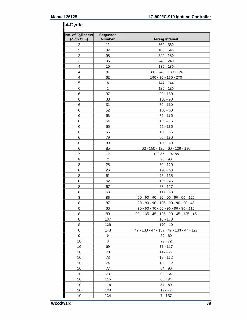
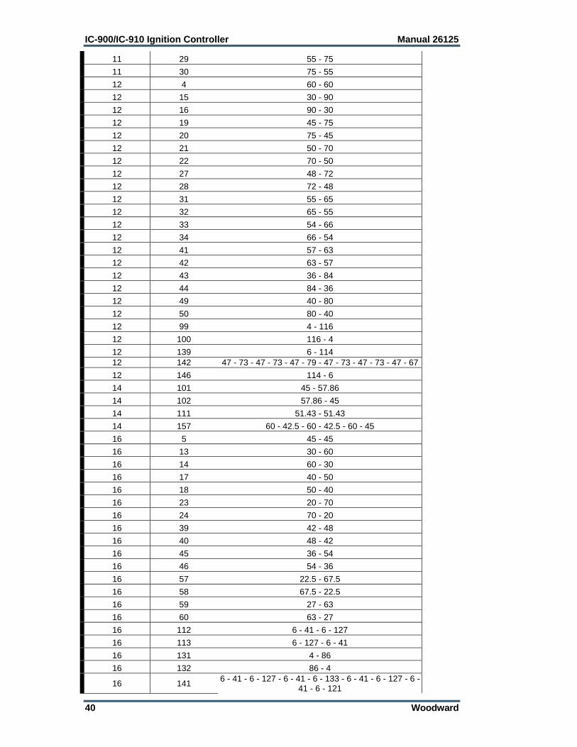
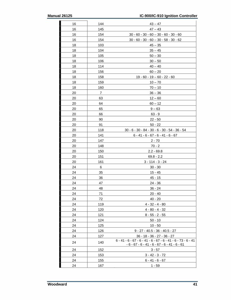
4-Cycle No. of Cylinders
(4-CYCLE) Sequence Number Firing Interval
2 11 360 - 360
2 97 180 - 540
2 98 540 - 180
3 96 240 - 240
4 10 180 - 180
4 81 180 - 240 - 180 - 120
4 82 180 - 90 - 180 - 270
5 8 144 - 144
6 1 120 - 120
6 37 90 - 150
6 38 150 - 90
6 51 60 - 180
6 52 180 - 60
6 53 75 - 165
6 54 165 - 75
6 55 55 - 185
6 56 185 - 55
6 79 60 - 180
6 80 180 - 60
6 85 60 - 180 - 120 - 60 - 120 - 180
7 12 102.86 - 102.86
8 2 90 - 90
8 25 60 - 120
8 26 120 - 60
8 61 45 - 135
8 62 135 - 45
8 67 63 - 117
8 68 117 - 63
8 86 90 - 90 - 90 - 60 - 90 - 90 - 90 - 120
8 87 90 - 90 - 90 - 135 - 90 - 90 - 90 - 45
8 88 90 - 90 - 90 - 65 - 90 - 90 - 90 - 115
8 89 90 - 135 - 45 - 135 - 90 - 45 - 135 - 45
8 137 10 - 170
8 138 170 - 10
8 143 47 - 133 - 47 - 139 - 47 - 133 - 47 - 127
9 9 80 - 80
10 3 72 - 72
10 69 27 - 117
10 70 117 - 27
10 73 12 - 132
10 74 132 - 12
10 77 54 - 90
10 78 90 - 54
10 115 60 - 84
10 116 84 - 60
10 133 137 - 7
10 134 7 - 137
IC-900/IC-910 Ignition Controller Manual 26125
40 Woodward
11 29 55 - 75
11 30 75 - 55
12 4 60 - 60
12 15 30 - 90
12 16 90 - 30
12 19 45 - 75
12 20 75 - 45
12 21 50 - 70
12 22 70 - 50
12 27 48 - 72
12 28 72 - 48
12 31 55 - 65
12 32 65 - 55
12 33 54 - 66
12 34 66 - 54
12 41 57 - 63
12 42 63 - 57
12 43 36 - 84
12 44 84 - 36
12 49 40 - 80
12 50 80 - 40
12 99 4 - 116
12 100 116 - 4
12 139 6 - 114 12 142 47 - 73 - 47 - 73 - 47 - 79 - 47 - 73 - 47 - 73 - 47 - 67
12 146 114 - 6
14 101 45 - 57.86
14 102 57.86 - 45
14 111 51.43 - 51.43
14 157 60 - 42.5 - 60 - 42.5 - 60 - 45
16 5 45 - 45
16 13 30 - 60
16 14 60 - 30
16 17 40 - 50
16 18 50 - 40
16 23 20 - 70
16 24 70 - 20
16 39 42 - 48
16 40 48 - 42
16 45 36 - 54
16 46 54 - 36
16 57 22.5 - 67.5
16 58 67.5 - 22.5
16 59 27 - 63
16 60 63 - 27
16 112 6 - 41 - 6 - 127
16 113 6 - 127 - 6 - 41
16 131 4 - 86
16 132 86 - 4
16 141 6 - 41 - 6 - 127 - 6 - 41 - 6 - 133 - 6 - 41 - 6 - 127 - 6 -
41 - 6 - 121
Manual 26125 IC-900/IC-910 Ignition Controller
Woodward 41
16 144 43 – 47
16 145 47 – 43
16 154 30 - 60 - 30 - 60 – 30 - 60 - 30 - 60
16 154 30 - 60 - 30 - 60 – 30 - 58 - 30 - 62
18 103 45 – 35
18 104 35 – 45
18 105 50 – 30
18 106 30 – 50
18 114 40 – 40
18 156 60 – 20
18 158 19 - 60 - 19 – 60 - 22 - 60
18 159 10 – 70
18 160 70 – 10
20 7 36 – 36
20 63 12 – 60
20 64 60 – 12
20 65 9 – 63
20 66 63 - 9
20 90 22 - 50
20 91 50 - 22
20 118 30 - 6 - 30 - 84 - 30 - 6 - 30 - 54 - 36 - 54
20 141 6 - 41 - 6 - 67 - 6 - 41 - 6 - 67
20 147 2 - 70
20 148 70 - 2
20 150 2.2 - 69.8
20 151 69.8 - 2.2
20 161 3 - 114 - 3 - 24
24 6 30 - 30
24 35 15 - 45
24 36 45 - 15
24 47 24 - 36
24 48 36 - 24
24 71 20 - 40
24 72 40 - 20
24 119 4 - 32 - 4 - 80
24 120 4 - 80 - 4 - 32
24 121 8 - 55 - 2 - 55
24 124 50 - 10
24 125 10 - 50
24 126 9 - 27 - 40.5 - 36 - 40.5 - 27
24 127 36 - 18 - 36 - 27 - 36 - 27
24 140 6 - 41 - 6 - 67 - 6 - 41 - 6 - 67 - 6 - 41 - 6 - 73 - 6 - 41
- 6 - 67 - 6 - 41 - 6 - 67 - 6 - 41 - 6 - 61
24 152 3 - 57
24 153 3 - 42 - 3 - 72
24 155 6 - 41 - 6 - 67
24 167 1 - 59

IC-900/IC-910 Ignition Controller Manual 26125
42 Woodward
IC-900/IC-910 Programming Flowchart
Pro
gra
m M
ode
Num
ber
of
Teeth
(60-5
00)
F5
F4
F2
F3
Sequence N
um
ber
(1-1
31)
F5
F4
F2
F3
Reset
Positio
n
F5
F4
F2
F3
Overs
peed
F5
F4
F2
F3
Securi
ty S
peed
F5
F4
F2
F3
Num
ber
of
cylin
ders
(1-2
4)
F5
F4
Valid
Passw
ord
& R
PM
=0 S
ave
Help
Save
Help
Save
Help
Save
Help
Save
Help
Save
Help
Mis
-Fir
e R
ate
F5
F4
F2
F3
CA
N I
D a
ddre
ss
F5
F4
F2
F3
CA
N(e
nable
/dis
able
d)
F5
F4
F2
F3
Schedule
B(e
nable
/dis
able
)F
5
F4
F2
F3
Speed C
urv
e in A
(enable
/dis
able
)F
5
F4
F2
F3
4-2
0m
a t
imin
g in A
(enable
/dis
able
)F
5
F4
F2
F3
Save
Help
Save
Help
Save
Help
Save
Help
Save
Help
Save
Help
Speed c
urv
e in B
(enable
/dis
able
)F
5
F4
F2
F3
4-2
0m
a t
imin
g in B
(enable
/dis
able
)F
5
F4
F2
F3
Pot
AT
imin
g a
t C
CW
F5
F4
F2
F3
Pot
AT
imin
g a
t C
WF
5
F4
F2
F3
Schedule
AM
ax.
Advance
F5
F4
F2
F3
Schedule
AM
ax.
Reta
rdF
5
F4
F2
F3
Save
Help
Save
Help
Save
Help
Save
Help
Save
Help
Save
Help
Note
: H
ittin
g E
SC
at anyt
ime e
xits
the p
rogra
m m
ode
AB
AB
CD
CD
Pot
BT
imin
g a
t C
CW
F5
F4
F2
F3
Pot
BT
imin
g a
t C
WF
5
F4
F2
F3
Schedule
BM
ax.
Advance
F5
F4
F2
F3
Schedule
BM
ax.R
eta
rdF
5
F4
F2
F3
4-2
0m
A T
imin
gT
imin
g a
t 4m
aF
5
F4
F2
F3
4-2
0m
A T
imin
gT
imin
g a
t 20m
aF
5
F4
F2
F3
Save
Help
Save
Help
Save
Help
Save
Help
Save
Help
Save
Help
EF
4-2
0m
A T
imin
gD
efa
ult T
imin
gF
5
F4
F2
F3
Speed C
urv
eN
um
ber
of
Bre
akpoin
ts
F5
F4
F2
F3
Bre
akpoin
t 1
RP
MF
5
F4
F2
F3
Bre
akpoin
t 1
Tim
ing
F2
F3
F2
F3
Save
Help
Save
Help
Save
Help
GH
F5
F4
Save
Help
Bre
akpoin
t 2
RP
MF
5
F4
Bre
akpoin
t 2
Tim
ing
F2
F3
F2
F3
Save
Help
F5
F4
Save
Help
Last
Bre
akpoin
tR
PM
F5
F4
Last
Bre
akpoin
tT
imin
g
F2
F3
F2
Save
Help
F5
F4
Save
Help
F2
F3
I
EF
GH
F2
F3
F2
F3
F2
F3
F2
F3
F2I
IC-9
00
Pro
gra
mm
ing F
low
chart

Manual 26125 IC-900/IC-910 Ignition Controller
Woodward 43
IC-900/IC-910 Configuration Form Customer Engine Type/Model Engine Serial NumberIgnition Timing Point(1) Number of Cylinders (2) Number of Teeth (3) Sequence Number (4) Reset Position Nominal: Actual: (5) Overspeed (6) Security Speed (7) Misfire Rate (8) Speed Trigger 1 (IC-910) rpm (9) Hysteresis 1 (IC-910) rpm (10) Speed Trigger 2 (IC-910) rpm (11) Hysteresis 2 (IC-910) rpm (12) CAN ID (13) CAN Enable Enable Disable (14) Cyl-to-Cyl Timing Enable Disable (15) Schedule A or B (16) Speed Curve in A Enable Disable (17) 4–20 mA in A Enable Disable (18) Speed Curve in B Enable Disable (19) 4–20 mA in B Enable Disable (20) Pot A Max CCW ADV (BTDC) RET (ATDC) (21) Pot A Max CW ADV (BTDC) RET (ATDC) (22) Max Advance for A ADV (BTDC) RET (ATDC) (23) Max Retard for A ADV (BTDC) RET (ATDC) (24) Pot B Max CCW ADV (BTDC) RET (ATDC) (25) Pot B Max CW ADV (BTDC) RET (ATDC) (26) Max Advance for B ADV (BTDC) RET (ATDC) (27) Max Retard for B ADV (BTDC) RET (ATDC) (28) 4 mA Timing ADV (BTDC) RET (ATDC) (29) 20 mA Timing ADV (BTDC) RET (ATDC) (30) Default 4–20 mA Timing ADV (BTDC) RET (ATDC) (31) No. of Speed Points (32) Speed Curve Data (a) BP1 Speed rpm Timing ADV (BTDC) RET (ATDC) (b) BP2 Speed rpm Timing ADV (BTDC) RET (ATDC) (c) BP3 Speed rpm Timing ADV (BTDC) RET (ATDC) (d) BP4 Speed rpm Timing ADV (BTDC) RET (ATDC) (e) BP5 Speed rpm Timing ADV (BTDC) RET (ATDC) (33) Auto Energy Enable Disable (34) Spark Duration SP
Run-Time ControlsCylinder-to-Cylinder Command: Upper Case “C” Energy Control Command: Upper Case “E” Hour Meter Command: Upper Case “H” Misfire Rate Command: Upper Case “M”

We appreciate your comments about the content of our publications.
Send comments to: [email protected]
Please reference publication 26125A.
PO Box 1519, Fort Collins CO 80522-1519, USA 1000 East Drake Road, Fort Collins CO 80525, USA Phone +1 (970) 482-5811 Fax +1 (970) 498-3058
Email and Website—www.woodward.com
Woodward has company-owned plants, subsidiaries, and branches, as well as authorized distributors and other authorized service and sales facilities throughout the world.
Complete address / phone / fax / email information for all locations is available on our website.
2012/8/Colorado