20090122 Positive Attitude and Inter Personal Relations - 42s Ati Epi

ibright® Installation Guide IIG-1-2-20090122

P2 of 73 - IIG-1-2-20090122 - ©International Telematics Ltd - Commercial in Confidence
Contents
ibright® Installation Guide .......................................................................................................................................................................... 1
Copyright Notice and Disclaimer ............................................................................................................................................................. 6
Federal Communications Commission Statement ........................................................................................................................... 7
DECLARATION OF CONFORMITY WITH FCC RULES FOR ELECTROMAGNETIC COMPATIBILITY...................... 7
Caution: Exposure to Radio Frequency Radiation ........................................................................................................... 7
Federal Communications Commission Notice ................................................................................................................. 7
Modifications ................................................................................................................................................................................ 7
Contact Information ..................................................................................................................................................................................... 8
For more information, please contact:................................................................................................................................................... 8
Getting Help .................................................................................................................................................................................................... 9
Types of Help ...................................................................................................................................................................................... 9
Overview ........................................................................................................................................................................................................ 10
For Whom is this Guide? .............................................................................................................................................................. 10
International Telematics' Expectations .................................................................................................................................. 10
Certification and Compliance Requirements for Installers - US .................................................................................... 11
How Does the ibright® Solution Work? .................................................................................................................................. 12
Planning and Coordinating Installations ........................................................................................................................................... 13
Pilot Installations ............................................................................................................................................................................ 13
Major Installations .......................................................................................................................................................................... 13
General Installation Considerations ........................................................................................................................................ 14
Asset Warranty Conditions ......................................................................................................................................................... 14
Health and Safety Precautions .................................................................................................................................................. 14
Drilling and Cutting Precautions .............................................................................................................................................. 15
Installation Documentation .................................................................................................................................................................... 16
Installation and Work Repair Form (IWRF) ............................................................................................................................ 16
Camera ............................................................................................................................................................................................... 16
Tools and Equipment ................................................................................................................................................................................ 17
Access Tools and Equipment ..................................................................................................................................................... 17
Wiring Tools and Accessories .................................................................................................................................................... 17
ibright® Mounting Tools .............................................................................................................................................................. 17

IIG-1-2-20090122 ©International Telematics Ltd - Commercial in Confidence - P3 of 73
Hardware Components ............................................................................................................................................................................ 18
Basic Kit Box ..................................................................................................................................................................................... 18
ibright® X-Series Unit .............................................................................................................................................................. 18
Power Loom with Inline Fuse .............................................................................................................................................. 19
Blade Fuse, 5 Amp Plugin ATQ ............................................................................................................................................ 19
Blade Fuse Holder .................................................................................................................................................................... 19
ibright® X-Series Mounting Bracket................................................................................................................................... 20
Mounting Screws ..................................................................................................................................................................... 20
Rubber Port Protection Grommet...................................................................................................................................... 20
Cable Tie ...................................................................................................................................................................................... 21
Security Stickers........................................................................................................................................................................ 21
Optional Components .................................................................................................................................................................. 22
6/9 Pin J-Bus Y Cable ............................................................................................................................................................... 22
20 Way Loom ............................................................................................................................................................................. 22
18 Way Loom ............................................................................................................................................................................. 23
AutoTap ....................................................................................................................................................................................... 23
External GPS Antenna ............................................................................................................................................................ 24
External GSM Antenna (US Only) ....................................................................................................................................... 24
External GSM Stub Antenna (NZ Only) ............................................................................................................................. 24
External Combo Antenna (US Only) .................................................................................................................................. 25
Thermoking iBox Sensor ....................................................................................................................................................... 25
MDT (Mobile Data Terminal) ................................................................................................................................................ 26
RAM Mounting Bracket for MDT ......................................................................................................................................... 26
Ports and Connections ............................................................................................................................................................................. 28
ibright® X-Series Ports - Overview ............................................................................................................................................ 28
ibright® X-Series 18 Pin Port ....................................................................................................................................................... 28
ibright® X-Series 20 Pin Port ....................................................................................................................................................... 29
6-Pin J-Bus Connector .................................................................................................................................................................. 30
9-Pin J-Bus Connector .................................................................................................................................................................. 31
Connectivity Options ................................................................................................................................................................................ 32
Connectivity Options .................................................................................................................................................................... 32

P4 of 73 - IIG-1-2-20090122 - ©International Telematics Ltd - Commercial in Confidence
Internal Antennas ........................................................................................................................................................................... 32
Bluetooth Coverage Area ............................................................................................................................................................ 32
Pre-Installation Checks ............................................................................................................................................................................. 34
Pre-Installation Electrical Checks .............................................................................................................................................. 34
Assemble Tools and Components ........................................................................................................................................... 34
Scope Protocols .............................................................................................................................................................................. 35
Scope Fusebox Location .............................................................................................................................................................. 35
Scope and Test Power Supply to ibright® Unit / Autotap ................................................................................................ 35
Scope Ground (Earth) Point ........................................................................................................................................................ 35
Scope True Ignition, Cable Path ................................................................................................................................................ 35
Scope J-Bus Plug Location .......................................................................................................................................................... 36
Scope ibright® Unit Location and Position ........................................................................................................................... 36
Scope External Antenna Locations .......................................................................................................................................... 39
Scope MDT Location ..................................................................................................................................................................... 40
Scope PLC Reader / PLC ID Positions and Wiring ............................................................................................................... 40
Scope Dallas ID Tag / Reader Location ................................................................................................................................... 41
Installation..................................................................................................................................................................................................... 42
Things to Remember when Installing ..................................................................................................................................... 43
SIM Card Installation ..................................................................................................................................................................... 44
External Antenna Installation .................................................................................................................................................... 46
Ground (Earth) Wiring .................................................................................................................................................................. 47
J-Bus Connection............................................................................................................................................................................ 48
AutoTap Installation ...................................................................................................................................................................... 49
Power Wiring ................................................................................................................................................................................... 50
ibright® X-Series Unit Wiring ...................................................................................................................................................... 51
Bracket Preparation ....................................................................................................................................................................... 52
MDT Installation .............................................................................................................................................................................. 54
Dallas ID ............................................................................................................................................................................................. 55
Making Connections, Port Protection ..................................................................................................................................... 56
Status Indicators and Status Testing ....................................................................................................................................... 57
Final Unit Mounting ...................................................................................................................................................................... 58

IIG-1-2-20090122 ©International Telematics Ltd - Commercial in Confidence - P5 of 73
Post Installation ........................................................................................................................................................................................... 59
Post-install Testing ........................................................................................................................................................................ 59
Appendices ................................................................................................................................................................................................... 61
Troubleshooting ............................................................................................................................................................................. 62
Asset appears offline in ibright® Enterprise .................................................................................................................... 62
Green (power) and red (GPRS) LEDs are on but orange (GPS) is flashing ............................................................ 62
Green (power) LED is on and red (GPS) is flashing ....................................................................................................... 62
LEDs are all off on ibright® unit ........................................................................................................................................... 63
Odometer reading not present in ibright® Enterprise ................................................................................................ 63
Wire Loom Parts and Ordering Codes .................................................................................................................................... 64
Resources .......................................................................................................................................................................................... 65
J-Bus Plug Location Reference .................................................................................................................................................. 66
Wiring Overview Diagram ........................................................................................................................................................... 67
Glossary .......................................................................................................................................................................................................... 69
Index ................................................................................................................................................................................................................ 71

P6 of 73 - IIG-1-2-20090122 - ©International Telematics Ltd - Commercial in Confidence
Copyright Notice and Disclaimer ©2008 International Telematics Limited, International Telematics Inc and Ingenitech (NZ) Limited. All rights
reserved. International Telematics, Ingenitech and ibright® are either registered trade marks or trade marks of
International Telematics Limited, International Telematics Inc and Ingenitech (NZ) Limited ("we", "our", "us") in
New Zealand and other countries. The names of other companies and products mentioned in this document
may be the trade marks of their respective owners.
The information contained in this document represents our current views on the subject matter as at the date of
publication. Given that we will respond to changing market conditions, this document should not be
interpreted to be any form of commitment on the part of either company. We do not guarantee the accuracy of
the information in this document after the date of its publication.
This document is for information purposes only. We make no warranties, express or implied, as to the
information in this document. Complying with all applicable copyright laws is the responsibility of the user.
Without limiting our rights under copyright, no part of this document may be reproduced, stored in or
introduced into a retrieval system, or transmitted in any form or by any means (electronic, mechanical,
photocopying, recording, or otherwise), for any purpose, without our express written permission.
We may own patents, patent applications, trade marks, copyright, and other intellectual property rights
covering subject matter in this document. Except as expressly provided in any written licence agreement from
us, the providing of this document does not give the user any licence under such patents, trade marks,
copyright, or intellectual property rights.

IIG-1-2-20090122 ©International Telematics Ltd - Commercial in Confidence - P7 of 73
Federal Communications Commission Statement DECLARATION OF CONFORMITY WITH FCC RULES FOR ELECTROMAGNETIC
COMPATIBILITY
We, Ingenitech (NZ) Limited, of 3A, 125 The Strand, Parnell, Auckland 1010, New Zealand, declare under our sole
responsibility that the product, TMU1000 (ibright® X-Series unit), to which this declaration relates, complies
with Part 15 of the FCC Rules.
Operation is subject to the following two conditions:
• This device may not cause harmful interference, and
• This device must accept any interference received, including interference that may cause undesired
operation.
Caution: Exposure to Radio Frequency Radiation
The radiated output power of the TMU1000 is well below the Federal Communications Commission (FCC) radio
frequency exposure limits.Nevertheless, it is important that the TMU1000 is installed and used in such a manner
that the potential for human contact during normal operation is minimized.
When connecting an external antenna to the TMU1000, the antenna shall be placed in such a manner to
minimize the potential for human contact during normal operation. To avoid the possibility of exceeding the
FCC Radio frequency exposure limits, human proximity to the antenna must not be less than 20 cm (8 inches)
during normal operation.
Federal Communications Commission Notice
This equipment has been tested and found to comply with the limits for a Class B digital device, pursuant to
Part 15 of the FCC Rules. These limits are designed to provide reasonable protection against harmful
interference in a typical fleet asset installation.
This equipment generates, uses, and can radiate radio frequency energy and, if not installed and used in
accordance with the instructions, it may cause harmful interference to radio or television communications. There
is no guarantee that interference will not occur at any particular installation. If the TMU1000 does cause harmful
interference to radio or television communications, which can be determined by turning the equipment off and
on, the user is encouraged to try and correct the interference by one or more of the following measures:
• Re-orient or relocate the radio or television device's receiving antenna.
• Increase the distance between the TMU1000 and the radio or television device.
• Connect the TMU1000 to a power supply on a circuit different to the circuit to which the radio or television
device is connected.
• Consult the dealer or an experienced radio/TV technician for help.
Modifications
The FCC requires the user to be notified that any changes or modifications to this device that are not expressly
approved by Ingenitech (NZ) Limited may void the user's authority to operate the equipment.

P8 of 73 - IIG-1-2-20090122 - ©International Telematics Ltd - Commercial in Confidence
Contact Information North America
New York:
International Telematics Corporation
311 West 43rd Street, Suite 304
New York
NY 10036
United States
P: +1 646 595 8482
F: +1 646 485 1960
Minnesota:
International Telematics Corporation
420 Summit Avenue
St Paul
MN 55102
United States
P: +1 888 887 0935
F: +1 651 224 1746 Europe
International Telematics Limited (UK)
1 Northumberland Avenue
Trafalgar Square
London
WC2N 5BW
United Kingdom
P: +44 7881 820 256
New Zealand
International Telematics Limited
3A, 125 The Strand
P O Box 37037
Parnell
Auckland
New Zealand
P: +64 9 379 7211
F: +64 9 379 7212
W: www.internationaltelematics.com
Ingenitech Limited
3A, 125 The Strand
P O Box 37037
Parnell
Auckland
New Zealand
P: +64 9 308 4007
F: +64 9 379 7212
W: www.ingenitech.co.nz
For more information, please contact:
Brendan Hay
Telematics Specialist
International Telematics Limited
3A, 125 The Strand
P O Box 37037
Parnell
Auckland
New Zealand
P: +64 9 379 7211
F: +64 9 379 7212
M: +64 21 797 600
W: www.internationaltelematics.com

IIG-1-2-20090122 ©International Telematics Ltd - Commercial in Confidence - P9 of 73
Getting Help This topic covers how to use this help guide, the formatting and text conventions used in the guide, and where
you can find more help outside this guide.
Please check that you are using the latest version by looking at the version tracking table and the version
number on the title page.
Types of Help
PDF and HTML User Guides
Our guides are published in PDF format for printing, and in HTML format for online help accessible from the
software.
Technical Guides
Technical Guides are published in PDF format only. They are for limited distribution among technical personnel,
and usually cover installation related technical information in detail.
Web Resources
Please see our website (http://www.internationaltelematics.com) for corporate information, product
descriptions and media releases.
Multimedia Resources
A number of multimedia resources such as animations, videos and presentations are available on request. Please
contact us (see "Contact Information" on page 8) for more information.
Conventions
Formatting Convention
Bold Items that can be clicked, emphasis.
KEY + KEY A command key on the keyboard, such as CTRL, SHIFT, ALT,
HOME, END or DELETE, used in combination with another
key.
Step 1 > Step 2 > Step 3 This indicates a sequence that you should follow - for
example a book > chapter > topic sequence, or a menu >
submenu > submenu > item sequence.
Procedure This heading indicates a procedure and series of steps
(usually numbered).
[Variable] Text enclosed in square brackets indicates a variable, to be
replaced with the appropriate alternative according to the
context.
Consolas Source code.

P10 of 73 - IIG-1-2-20090122 - ©International Telematics Ltd - Commercial in Confidence
Overview This overview covers an introduction to the ibright® Solution and certification / compliance considerations for
installation personnel.
In This Section
For Whom is this Guide? 10
International Telematics' Expectations 10
Certification and Compliance Requirements for Installers - US 11
How Does the ibright® Solution Work? 12
For Whom is this Guide?
This guide is for installers of the ibright® Solution hardware.
It covers hardware, part and tool checklists, installation planning, installation best practice, post-install checks
including LED status conditions and troubleshooting.
The material in this guide falls into three overall sections.
• We first describe planning for the installation (see "Planning and Coordinating Installations" on page 13).
• Next, we describe the tools and equipment (on page 17), and hardware components (on page 18)
required for the installation.
• We then describe the pre-installation checks (on page 34) and the installation (on page 42) in detail.
If you're using this guide as a reference and you have already completed some stages of the process, you may
wish to use the links above, the Contents or the Index sections to go quickly to the section you require.
We also have Appendices that provide useful supplementary information.
International Telematics' Expectations
A quality installation is vital to ensure that the ibright® Solution performs in the expected manner.
An installation is only considered finished:
• When each unit is successfully connected and providing all the necessary data from the fleet asset to the
end application, and
• Each unit is registered online with all the serial number details of the ibright® units and fleet asset details.
International Telematics requires all installers to have read all the information in this ibright® Installation and
Operations guide prior to commencing any ibright® installations, and to follow all instructions in detail.
If there is any aspect of the installation that is not covered in this guide, or which you need further clarification
on, please do not hesitate to contact us (see "Contact Information" on page 8).

IIG-1-2-20090122 ©International Telematics Ltd - Commercial in Confidence - P11 of 73
Certification and Compliance Requirements for Installers - US
Installations of the ibright® Solution must be completed by a certified installer with the right (recognised)
qualifications.
Installing hardware when you are not a certified installer will negate the product warranties for you or your
customers. Incorrect installations are likely to result in the product not working, product damage, or poor
performance from the technology.
Installation specifics will depend upon the type of ibright® hardware being installed, and the unique aspects of
each fleet asset you are installing the unit/s into.
In ALL instances we recommend installers become familiar with fleet assets before an installation. If necessary
read the Owner's Manuals before installing equipment to qualify any power, connection locations or unique
elements that may affect the technology working properly and safely.
Minimum Requirements for Installers
• 3 years' installation experience.
• Customer references.
• Liability insurance.
Recommended Requirements for Installers
• MECP (Mobile Electronic Certified Professional) certification.
• Master Electrical Technician rating.

P12 of 73 - IIG-1-2-20090122 - ©International Telematics Ltd - Commercial in Confidence
How Does the ibright® Solution Work?
The ibright® Solution has three parts:
• ibright® telematic unit.
• Server.
• ibright® Enterprise software application.
The ibright® unit is an advanced telematic computer incorporating GPS, GSM and Bluetooth communications
technology.
It collects OBD-II, J1587 and J1939 data from the asset's internal microcontrollers, combines the data with
location information from GPS satellites, encrypts the data, and sends it over the Internet to the International
Telematics servers.
The servers decrypt the information, send SMS and email alerts if required, and prepare the data for viewing in
ibright® Enterprise within the ibright® middleware.
The information is then loaded into the ibright® Enterprise software for the customer to view.

IIG-1-2-20090122 ©International Telematics Ltd - Commercial in Confidence - P13 of 73
Planning and Coordinating Installations In This Section
Pilot Installations 13
Major Installations 13
General Installation Considerations 14
Asset Warranty Conditions 14
Health and Safety Precautions 14
Drilling and Cutting Precautions 15
Pilot Installations
The most important factor in a pilot installations of the ibright® Solution is to cover the widest possible range
of makes and models of fleet assets.
Next, the pilot installation needs to be documented thoroughly, to ensure that all the requirements and
variables applicable to any given installation context are captured.
This is not only useful in facilitating a smooth roll-out if the deal goes through, but also contributes to the
knowledge and experience of the installation team.
In particular, these should be documented:
• Installation environment restrictions (outdoors, indoors, asset availability, authorization).
• Placement of the ibright® Solution hardware and components.
• Best connections for ground/GND (earth), constant power and ignition/IGN (NOT Accessory/ACC).
• Unusual 3rd party hardware specific to the fleet (for example, MDTs).
• Resources - for example, contact personnel, drivers, technicians.
Major Installations
For a major installation, your first step should be to produce a roll-out plan.
In particular, these factors should be considered:
• Location of installations. We recommend that installations be performed in the open, as this allows GPS to
connect easier.
• Installation environment restrictions (outdoors, indoors, asset availability, authorization).
• Coordination of asset installations so that identical assets are installed together.
• Placement of the ibright® Solution hardware and components.
• Best connections for ground/GND (earth), constant power and ignition/IGN (NOT Accessory/ACC).
• Unusual 3rd party hardware specific to the fleet (for example, MDTs).
• Resources - for example, contact personnel, drivers, technicians.

P14 of 73 - IIG-1-2-20090122 - ©International Telematics Ltd - Commercial in Confidence
General Installation Considerations
The ibright® hardware SHOULD be installed:
1. In a secure area of the fleet asset, where it will be protected by the asset's security system.
2. So that tampering by unauthorized personnel is avoided.
3. Where accidental damage is least likely to occur.
4. So that cables are concealed from view, secure and cannot be loosened or stepped on.
5. So that components cannot easily be removed.
6. With screws or bolts, using lock-nuts or nuts with shake-proof washers, or rivets.
7. Firmly and securely, away from moving parts.
8. Soldered and insulated with heat-shrink insulation for crucial connections like POWER.
9. With all spliced wires taped and/or silicon sealed.
10. Away from sources of heat.
11. Away from sources of moisture. Test that all wiring points and installation points are dry.
12. With an anti static wrist band whilst handling SIM Cards.
The ibright® hardware should NOT be installed:
1. On harnesses, hoses, pipes or heater ducts.
2. Where it can create interference on audio head units.
3. Where it may protrude or obstruct in any way.
4. In a way that may constitute a hazard or contravene any applicable Health and Safety Standards.
5. In a way that ibright® components, cords or attachments vibrate or rattle.
6. Where it may chafe cables, pipes or the fleet asset's body during operation.
7. With 'quick tap' screws, as they are prone to corrosion and wiring failures.
Asset Warranty Conditions
The first responsibility of the installer is to thoroughly check all fleet asset warranty conditions, and whether any
or all of the ibright® hardware installation steps may void any of the asset warranties.
The customer has the discretion to halt the installation if there is a danger of voiding a warranty.
If this is the case, International Telematics must be promptly informed.
If the customer decides to proceed with the installation and void any warranties, confirmation must be gained in
writing.
Health and Safety Precautions
To safeguard the health and safety of all installers and take proper care of the customer's property, please
observe the following when doing an installation.
• Remove all ties and loose or unsecured items of clothing, to avoid these being caught on moving fleet asset
parts or hinder movement.
• Remove all accessories or sharp objects like jewellery or belt buckles that may scratch the body of the asset
or hinder movement.
• Wear protective eyewear, gloves and protective clothing as appropriate.

IIG-1-2-20090122 ©International Telematics Ltd - Commercial in Confidence - P15 of 73
• Wearing a high visibility (hi-vis) vest is recommended at all times, and is mandatory for work on open roads
or open areas.
• Adequate, independently powered lighting is recommended for night installations.
Drilling and Cutting Precautions
Warning: Do not drill or cut anything for pilot installations.
1. Always read the asset's owners manual for any special instructions before commencing.
2. Before drilling ensure there are no obstructions, pipes or cables on either side of the panel to be drilled.
3. Check that any equipment or wiring or equipment has not been damaged once drilling or cutting is
complete.
4. Remove any rough edges and filings dropped from holes drilled.
5. Protect any drilled holes or cut edges using a recognized anti-corrosion treatment.
6. Fit suitable grommets where wiring is to be routed through body panels and ensure grommets through
engine bulk-heads are water and gas tight.
7. Ensure the structural integrity of the asset will not be reduced.
8. Ensure the technicians are aware of any manufacturers instructions regarding corrosion, particularly on
aluminium assets.

P16 of 73 - IIG-1-2-20090122 - ©International Telematics Ltd - Commercial in Confidence
Installation Documentation Documenting the environment before an installation, during the installation and after the installation is crucial.
Doing so will not only capture essential reference information, but will also safeguard you in the event of a
problem with the installation.
In This Section
Installation and Work Repair Form (IWRF) 16
Camera 16
Installation and Work Repair Form (IWRF)
An Installation and Work Repair Form (IWRF) is provided to each installer to document all steps of the
installation.
This form is designed to capture ALL relevant asset and installation environment information.
It is also helpful as a checklist of the installation steps.
It is printed and filled in during the installation. A PDF copy of the form can be downloaded from the
International Telematics Support website (http://support.itelematic.com). You can also contact us (see "Contact
Information" on page 8).
Note: Completing the IWRF is essential - the unit will not be provisioned unless a completed form is received at
International Telematics.
Camera
A camera or some sort of image capture device is essential for the installation.
This is to record anything important or unusual before beginning the installation, while doing the installation
and after it also. This is not only for reference, but as a safeguard against being held responsible for faults that
existed before the installation began.

IIG-1-2-20090122 ©International Telematics Ltd - Commercial in Confidence - P17 of 73
Tools and Equipment This section covers the tools and equipment you will require for International Telematics installations.
In This Section
Access Tools and Equipment 17
Wiring Tools and Accessories 17
ibright® Mounting Tools 17
Access Tools and Equipment • Socket set (minimum 40 Piece recommended, torque bits are required).
• Screwdriver set (various size flat and Phillips drivers).
• Flashlight.
• Electrostatic Wristband.
Wiring Tools and Accessories • Wire Stripping tool/ knife.
• Crimping Tool.
• Multimeter.
• Soldering iron.
• Rosin Core Solder.
• Spare Automotive grade wire (16 – 18 AWG).
• Automotive wire.
• Connectors.
• Electrical Insulation Tape.
• Spare 3 amp fuses.
• Terminal Brush.
• Cleaning Alcohol wipes.
• Heat Shrink.
ibright® Mounting Tools • Industrial Velcro.
• Industrial double sided tape.
• Silicone Sealant.
• Various screws (self tappers).
• Spare nuts & bolts.
• Spare washers (as required for installation).
• Cable ties (various lengths).

P18 of 73 - IIG-1-2-20090122 - ©International Telematics Ltd - Commercial in Confidence
Hardware Components This section describes the standard and optional components that may be used for a typical installation.
In This Section
Basic Kit Box 18
Optional Components 22
Basic Kit Box
The white basic kit box supplied to all International Telematics installers has a number of standard components
included with it. Only the ibright® unit itself has a part code, as the included components are considered part of
the basic kit.
The topics below describe the components individually.
ibright® X-Series Unit • Description: ibright® X-Series Unit with built-in accelerometer, GPS, Bluetooth and GPRS connectivity.
• Code: TDV-XSER-1.2a.

IIG-1-2-20090122 ©International Telematics Ltd - Commercial in Confidence - P19 of 73
Power Loom with Inline Fuse
• Description: 2m power loom with in-line 3amp fuse and wiring for ignition and Dallas ID connections
included.
Note: The power loom is not required when using J-Bus cables (see "6/9 Pin J-Bus Y Cable" on page 22) for the
installation.
Blade Fuse, 5 Amp Plugin ATQ
• Description: 5 amp blade fuse. Most often included with the power loom (above) but sometimes supplied
individually with a blue fuse block for installations requiring non-standard ignition wiring (below).
• Code: ACCFUSE5AMP-000.
Blade Fuse Holder
• Description: Blade fuse crimper / holder for installations requiring non-standard ignition wiring.
• NZ:

P20 of 73 - IIG-1-2-20090122 - ©International Telematics Ltd - Commercial in Confidence
• US (Code: ACC-FUSEHOLDER-000):
ibright® X-Series Mounting Bracket
• Description: Mounting bracket for ibright® X-Series Unit.
Mounting Screws
• Description: 4x mounting screws to be used with ibright® X-Series Mounting Bracket.
Rubber Port Protection Grommet
• Description: Rubber ingress protection IP55 grommet to protect the ibright® X-Series Unit ports from liquid
and dust contamination.
IIG-1-2-20090122 ©International Telematics Ltd - Commercial in Confidence - P21 of 73
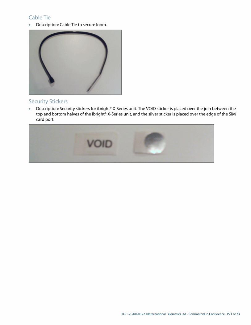
Cable Tie
• Description: Cable Tie to secure loom.
Security Stickers
• Description: Security stickers for ibright® X-Series unit. The VOID sticker is placed over the join between the
top and bottom halves of the ibright® X-Series unit, and the silver sticker is placed over the edge of the SIM
card port.

P22 of 73 - IIG-1-2-20090122 - ©International Telematics Ltd - Commercial in Confidence
Optional Components
A number of optional components are also available for specific installation needs. These components have a
part code for your convenience.
In This Section
6/9 Pin J-Bus Y Cable 22
20 Way Loom 22
18 Way Loom 23
AutoTap 23
External GPS Antenna 24
External GSM Antenna (US Only) 24
External GSM Stub Antenna (NZ Only) 24
External Combo Antenna (US Only) 25
Thermoking iBox Sensor 25
MDT (Mobile Data Terminal) 26
RAM Mounting Bracket for MDT 26
6/9 Pin J-Bus Y Cable
• Description: 6 and/or 9 pin J-Bus Y-cable serving the triple purpose of supplying power to the ibright® unit,
supplying power to the Autotap and transmitting/receiving data. This example shows the 6 pin Y-cable.
• Codes: LOO-YCABL6P-000 (6 pin Y-cable), LOO-YCABL9P-000 (9 pin Y-cable).
20 Way Loom
• Description: 20-way loom with serial connectors for attaching the Autotap and/or MDT to the ibright® X-
Series unit.

IIG-1-2-20090122 ©International Telematics Ltd - Commercial in Confidence - P23 of 73
• Code: LOO-20WAY-000.
18 Way Loom
• Description: 18-way loom for connections to the ibright® X-Series unit.
• Code: LOO-18WAY-000.
AutoTap
• Description: Microprocessor unit used for engine diagnostics.

P24 of 73 - IIG-1-2-20090122 - ©International Telematics Ltd - Commercial in Confidence
• Code: ACC-AUTO-000.
External GPS Antenna
• Description: External GPS antenna to extend the range of the GPS unit built in to the ibright® X-Series.
• Code: ANT-EXGPS-000.
Note: An external GPS antenna must have adequate 'sky view' to be able to acquire a GPS fix.
External GSM Antenna (US Only)
• Description: Glass mounted high gain external GSM antenna to extend the range of the GSM unit built in to
the ibright® X-Series. For US installations only.
• Code: ANT-EXGSMHG-001.
Note: Must be mounted on the windscreen.
External GSM Stub Antenna (NZ Only)
• Description: External GSM stub antenna to extend the range of the GSM unit built in to the ibright® X-Series.
This component is for NZ installations only.

IIG-1-2-20090122 ©International Telematics Ltd - Commercial in Confidence - P25 of 73
• Code: ANT-EXGSM-000.
External Combo Antenna (US Only)
• Description: External combination GSM / GPS antenna to extend the range of the GSM and GPS modules
built in to the ibright® X-Series. This component is for US installations only. 2 types are available.
Note: Mount on the roof of the asset, and run wires through light housings or the door jamb.
• Code: ANT-ARCGT-000 (ARC Titan).
• Code: ANT-ARCPM-000 (ARC PM).
Thermoking iBox Sensor • Description: Thermoking iBox Sensor for refrigerated unit assets.

P26 of 73 - IIG-1-2-20090122 - ©International Telematics Ltd - Commercial in Confidence
• Code: SENS-IBOX-000.
MDT (Mobile Data Terminal)
• Description: Multi-purpose MDT (Mobile Data Terminal) for messaging, alerts and diagnostic information.
Shown below is the Motia MDT.
• Code: DAT-MDT-000.
• A Mio MDT is also available.
RAM Mounting Bracket for MDT
• Description: RAM truck cab mounting bracket for MDT.

IIG-1-2-20090122 ©International Telematics Ltd - Commercial in Confidence - P27 of 73
• Code: DATA-VCD-000.

P28 of 73 - IIG-1-2-20090122 - ©International Telematics Ltd - Commercial in Confidence
Ports and Connections In This Section
ibright® X-Series Ports - Overview 28
ibright® X-Series 18 Pin Port 28
ibright® X-Series 20 Pin Port 29
6-Pin J-Bus Connector 30
9-Pin J-Bus Connector 31
ibright® X-Series Ports - Overview
Peripheral devices are connected directly to the ports show above.
The option existing to connect devices via Bluetooth if hard-wired connections are not possible.
The ibright® X-Series can accept both digital and analog connections.
• Digital Inputs enable sensors with on/off states to be connected - for example door, brake and seat belt
sensors. Digital Outputs provide events to be measured - for example, alarms, immobilizers.
• Analog inputs enable sensor readings to be constantly measured - for example, weight and temperature
sensors can use the four RS232/ RS485 ports to measure temperature for refrigeration units ('reefers').
Another example: the Dallas input pin allows connection of Driver ID sensing devices.
ibright® X-Series 18 Pin Port
The pin configuration and channel descriptions for the dedicated 18 pin port are detailed below.
Pin Signal Type
1 5.25v Supply Out Current Output (100mA max)
2 Analog In 1.1 0-5v
3 Analog In 1.3 0-5v
4 Analog In 1.5 0-5v
5 Analog In 1.7 0-5v

IIG-1-2-20090122 ©International Telematics Ltd - Commercial in Confidence - P29 of 73
6 Digital In 5 0-12v w/ 2v threshold
7 Digital In 7 0-12v w/ 2v threshold
8 Digital Out 2 Current Sink (300mA max)
9 Serial Receive 2 RS232 In (Equipment Tx)
10 Analog GND (Earth)* GND (Earth) for analog sensors
11 Analog In 1.2 0-5v
12 Analog In 1.4 0-5v
13 Analog In 1.6 0-5v
14 Digital GND (Earth)* GND (Earth) for serial devices and for digital sensors
15 Digital In 6 0-12v w/ 2v threshold
16 Digital In 8 0-12v w/ 2v threshold
17 Digital Out 3 Current sink 300mA max
18 Serial Transmit 2 RS232 Out (Equipment Rx)
*Do not connect to GND (Earth)
ibright® X-Series 20 Pin Port
The pin configuration and channel descriptions for the dedicated 20 pin port are detailed below.
Pin Signal Type
1 5.25v Supply Out Current Output (100mA max)
2 Analog In 0.1 0-5v
3 Analog In 0.3 0-5v
4 Analog In 0.5 0-5v
5 Analog In 0.7 0-5v
6 Digital In 1 0-12v w/ 2v threshold
7 Digital In 3 0-12v w/ 2v threshold
8 Digital Out 0 Current sink (300mA max)
9 Serial Receive 0 RS232 In (Equipment Tx) / RS485 - RxD In
10 Serial Receive 1 RS232 In (Equipment Tx) RS485 + In
11 Analog GND (Earth)* GND (Earth) for analog sensors
12 Analog In 0.2 0-5v
13 Analog In 0.4 0-5v

P30 of 73 - IIG-1-2-20090122 - ©International Telematics Ltd - Commercial in Confidence
14 Analog In 0.6 0-5v
15 Digital GND (Earth)* GND (Earth) for serial devices and for digital sensors
16 Digital In 2 0-12v w/ 2v threshold
17 Digital In 4 0-12v w/ 2v threshold
18 Digital Out 1 Current sink (300mA max)
19 Serial Transmit 0 RS232 Out (Equipment Rx) / RS485 TxD - Out, RxD - In
(Half Duplex)
20 Serial Transmit 1 RS232 Out (Equipment Rx) / RS485 TxD + Out, RxD + In
(Half Duplex)
*Do not connect to GND (Earth)
6-Pin J-Bus Connector
Older assets using the SAE J1587 protocol use a 6-pin J-Bus connector.
The pins and cable descriptions are as follows.
Pin Description Wire Color in Loom
A J1587 + (Data +) Green
B J1587 - (Data -) Blue
C 12v Power Supply* Red
D Not used
E 0v (Ground / Earth) Black
F Not used
*Check for constant power even when the asset ignition is off.

IIG-1-2-20090122 ©International Telematics Ltd - Commercial in Confidence - P31 of 73
9-Pin J-Bus Connector
Modern assets use a 9-pin J-Bus connector that can handle both SAE J1587 and J1939 protocols.
The pins and cable descriptions are as follows.
Pin Description Wire Color in Loom
A Ground (Earth) Black
B 12v Power Supply* Red
C J1939 + (Data +) Yellow
D J1939 - (Data -) Brown
E J1939 Shield White
F J1587 + (Data +) Green
G J1587 - (Data -) Blue
H Not used
I Not used
J Not used
*Check for constant power even when the asset ignition is off.

P32 of 73 - IIG-1-2-20090122 - ©International Telematics Ltd - Commercial in Confidence
Connectivity Options In This Section
Connectivity Options 32
Internal Antennas 32
Bluetooth Coverage Area 32
Connectivity Options
The ibright® X-Series and D-Series units offer a number of connectivity options, both wireless and wired.
Wireless Connectivity
• Bluetooth Class 1 for up to 4 peripheral devices.
• GPRS/GSM mobile network connectivity.
Wired Connectivity Using Ports
• 9 x Digital inputs.
• 4 x Digital outputs.
• 4 x RS232/RS485 ports.
• 14 x analog inputs.
• 1 x Dallas input wire.
• Mini USB Host.
• SD (Secure Digital) card host.
Internal Antennas
The ibright® X-Series has internal GPS and GPRS antennas.
Where connectivity or acquiring a satellite lock is difficult with the internal antennas, external antennas should
be connected as shown in the illustration below.
See Antenna Positions (see "Scope External Antenna Locations" on page 39) for more information on installing
external antennas.
Bluetooth Coverage Area
The ibright® X-Series unit incorporates Class 1 Bluetooth connectivity for up

IIG-1-2-20090122 ©International Telematics Ltd - Commercial in Confidence - P33 of 73
to four peripheral devices.
Class 1 Bluetooth will provide a secure connectivity and coverage area of up to 60m around an asset.

P34 of 73 - IIG-1-2-20090122 - ©International Telematics Ltd - Commercial in Confidence
Pre-Installation Checks This section describes the scoping and pre-installation checks to be done before performing an ibright®
hardware installation.
We also expect that you have already covered the procedures involved in Planning and Coordinating
Installations (on page 13) above.
Use this section in conjunction with the Installation and Work Repair Form (IWRF) (on page 16) and document all
of the following, both on the form and with photographs or digital images (see "Camera" on page 16) for the
record.
In This Section
Pre-Installation Electrical Checks 34
Assemble Tools and Components 34
Scope Protocols 35
Scope Fusebox Location 35
Scope and Test Power Supply to ibright® Unit / Autotap 35
Scope Ground (Earth) Point 35
Scope True Ignition, Cable Path 35
Scope J-Bus Plug Location 36
Scope ibright® Unit Location and Position 36
Scope External Antenna Locations 39
Scope MDT Location 40
Scope PLC Reader / PLC ID Positions and Wiring 40
Scope Dallas ID Tag / Reader Location 41
Step 1
Pre-Installation Electrical Checks
A pre-installation electrical check is absolutely crucial to check and document the condition of the lights,
indicators, accessories and any other electrical equipment already installed in each fleet asset.
International Telematics requires that all installation companies and installers perform pre- and post-installation
electronic checks to ensure that the installation has not affected the working condition of the asset.
The pre-installation electrical checklist and steps are on the Installation and Work Repair Form (IWRF) (on page
16).
A summary of the checks are below.
• External Lights.
• Electronics and Ignition.
• Internal Lights.
Any additional accessories or electronic equipment should be photographed, tested and described in the
Equipment Comments field of the Other Equipment section of the IWRF.
Step 2
Assemble Tools and Components
Assemble all required tools (see "Tools and Equipment" on page 17) and hardware components (on page 18).

IIG-1-2-20090122 ©International Telematics Ltd - Commercial in Confidence - P35 of 73
Step 3
Scope Protocols
Find out what sort of asset is being installed, and whether it will require J-Bus (US and European manufacturers)
or Linetap (Japanese manufacturers).
Step 4
Scope Fusebox Location
Find the location of the fusebox. This may be needed for the power supply.
Step 5
Scope and Test Power Supply to ibright® Unit / Autotap
The power supply to the ibright® unit and the Autotap is important. The ibright® X-Series requires a constant
(not switched) power supply. This will either be 12v (US / European asset) or 24v (Japanese).
When using the J-Bus Y Cable (see "6/9 Pin J-Bus Y Cable" on page 22), tapping constant power and ground is
not required - this is handled by the cable, so you need to source just the ignition tap. If you're not using a J-Bus
cable (for example, for cars and smaller trucks), source tap points for all three - power, ground and ignition.
Look for all tap points behind the steering column.
Test the power source with a multimeter to ensure that there is a consistent voltage of between 10 to 28 volts. If
the positive voltage drops or exceeds this range, find an alternative power source within the asset. The power
supply voltage should not drop more than 0.5 volts between the mounting point and the battery.
Step 6
Scope Ground (Earth) Point
A good, secure ground point is essential.
You may need a ring terminal, crimped and connected with a bolt directly to the body of the asset.
Step 7
Scope True Ignition, Cable Path
The ignition wire will need to be fused, and other connections from the ibright® X-Series will be soldered directly
to it, so you must be absolutely certain of the location of the ignition wire.
Find and record the true ignition wire.
Also consult the customer on a cable path. The customer may have specific preferences on where the cables are
to be laid.

P36 of 73 - IIG-1-2-20090122 - ©International Telematics Ltd - Commercial in Confidence
Note: It's important to distinguish between accessory (ACC) and ignition (IGN) wires. ibright® hardware should
NOT be connected to the ACC cable as it is generally switched (controlled by the driver's key).
The inline 5 amp fuse (see "Blade Fuse, 5 Amp Plugin ATQ" on page 19) and fuse holder (see "Blade Fuse Holder"
on page 19) should be waterproofed.
Step 8
Scope J-Bus Plug Location
Locate the J-Bus Plug so that you can position the ibright® X-Series unit near it.
More information is available in the section above on Ports and Connections:
• 6-Pin J-Bus Connector (on page 30).
• 9-Pin J-Bus Connector (on page 31).
Step 9
Scope ibright® Unit Location and Position
It is absolutely crucial that the ibright® unit (and the bracket that holds it) be positioned properly so that the 3
axis accelerometer that the ibright® unit incorporates can function.
This is because each ibright® unit has a 3-axis accelerometer that measures G-forces. Its purpose is to measure
sudden acceleration or braking, swerving and more. For example, the accelerometer will generate alerts if a
driver has been in an accident.
To ensure that the accelerometer is properly calibrated, the ibright® unit must be installed only in the manner
described below, and its placement must be documented on the IWRF form (see "Installation and Work Repair
Form (IWRF)" on page 16).

IIG-1-2-20090122 ©International Telematics Ltd - Commercial in Confidence - P37 of 73
Scope possible positions for the ibright® unit as described below, and document any vehicle panels that may
need to be removed. A location as close as possible to the power supply and the J-Bus plug is recommended.
Overall Location Considerations
• The placement of ibright® unit, sensors or power cord should not hinder the driver or the passenger's
movements. This especially relates to the ibright® unit not obstructing movement around the pedals, gear
lever, handbrake, steering wheel, or the driver's seating position and view for driving.
• The ibright® unit must not be placed as to obstruct air-bag deployment, or any mechanical function of the
asset it is being installed into.

P38 of 73 - IIG-1-2-20090122 - ©International Telematics Ltd - Commercial in Confidence
Horizontal, Vertical and Lateral Position
The ibright® unit may be positioned either vertically, horizontally or lateral to the asset's X or Y axis, but never at
an angle.
The communication ports should face downwards for extra protection from moisture descending into the unit.

IIG-1-2-20090122 ©International Telematics Ltd - Commercial in Confidence - P39 of 73
Incorrect Installations
Below are some examples of how NOT to install the ibright® X-Series unit.
Step 10
Scope External Antenna Locations
2 internal antennas for GPS and GPRS are built in to the ibright® X-Series unit, but external antennas for either
GPS or GPRS may be required depending on network signal strength and operating environment (for example,
whether the asset will mainly be operating in a built-up environment, or mainly on highways / freeways).
Scope the position of the antennas as below.
Note: Any antenna externally connected to the ibright® unit is defined as an external antenna. This includes
external antennas installed both inside and outside the asset.
The external GPS antenna must always be installed in a position that will have sky view.
US Installations:
All installations, including pilots, should have external antennas. We recommend that the antennas be installed
on top of the roof of the asset.

P40 of 73 - IIG-1-2-20090122 - ©International Telematics Ltd - Commercial in Confidence
NZ Installations:
Use your judgement as to whether the external antenna should be located on the roof or inside the cab. Given
below are some typical in-cab locations that have been found to be adequate.
Step 11
Scope MDT Location
Note: For customers who have opted to install an MDT (Mobile Data Terminal). If this step is not required, feel
free to proceed to the next scoping step (see "Scope PLC Reader / PLC ID Positions and Wiring" on page
40), or go directly to Installation (on page 42).
The MDT (Mobile Data Terminal) unit must be installed securely, close enough to the driver to enable operation
while travelling, but protected as well as possible from the sun.
The installer should discuss location of the MDT with the driver and installer. The MDT cannot block the drivers
view, but if it includes built-in GPS, will require sky view.
Secure the bracket with bolts and screws, to insure that the MDT is securely mounted.
Step 12
Scope PLC Reader / PLC ID Positions and Wiring
Note: For customers who have opted to install PLC Trailer linking. If this step is not required, feel free to
proceed to the next scoping step (see "Scope Dallas ID Tag / Reader Location" on page 41), or go directly
to Installation (on page 42).
If the customer's enterprise requires PLC trailer linking, you need to scope locations for the 2 units and the cable
path.
PLC Reader
This is installed close to the ibright® unit, so there should be a reasonable amount of room for mounting and
wiring.
PLC ID
This unit is installed on the trailer, and must be within close proximity to the PLC connector (see below). It
should be protected from exposure to weather and dust.

IIG-1-2-20090122 ©International Telematics Ltd - Commercial in Confidence - P41 of 73
PLC cable path
The diagram below shows a typical cable path for a Volvo vehicle.
Tip: When cab is tipped forward, be careful about heavy objects at the back of the cab falling forward as well.
The cable from the cab follows the main wiring loom, through the chassis grommet near the arrow, along (and
inside) the chassis member until it emerges at the black connector.
Step 13
Scope Dallas ID Tag / Reader Location
Note: For customers who have opted to install an Dallas driver identification system. If this step is not required,
feel free to go directly to Installation (on page 42).
This is installed closer to the driver than the ibright® unit.
As the engine will not start unless the properly coded tag for an authorized driver is placed on the reader, the
Dallas reader should be within easy reach.
Most modern vehicle dashboards include blanks for accessory switches - we recommend using one of these.

P42 of 73 - IIG-1-2-20090122 - ©International Telematics Ltd - Commercial in Confidence
Installation This section covers installation procedures. We assume that you have already worked through the pre-
installation checks (on page 34).
Please keep General Installation Considerations (on page 14) in mind at all times.
In This Section
Things to Remember when Installing 43
SIM Card Installation 44
External Antenna Installation 46
Ground (Earth) Wiring 47
J-Bus Connection 48
AutoTap Installation 49
Power Wiring 50
ibright® X-Series Unit Wiring 51
Bracket Preparation 52
MDT Installation 54
Dallas ID 55
Making Connections, Port Protection 56
Status Indicators and Status Testing 57
Final Unit Mounting 58

IIG-1-2-20090122 ©International Telematics Ltd - Commercial in Confidence - P43 of 73
Things to Remember when Installing
Warning: Always connect cables before connecting POWER.
MDT / Autotap: connect the male DB9 connector to the Autotap and the female end to the MDT - use a
gender bender connector.
DO NOT use the BLUE wire - this is reserved for Driver ID.
Check the J-Bus connector for CONSTANT POWER. The ibright® X-Series should get power even when
the vehicle is OFF.
COMPLETE the IWRF (Installation and Work Repair Form).

P44 of 73 - IIG-1-2-20090122 - ©International Telematics Ltd - Commercial in Confidence
Step 14
SIM Card Installation
Please keep General Installation Considerations (on page 14) in mind at all times.
Note: The following steps are required only if the ibright® X-Series is delivered without the SIM card installed.
Generally we supply ibright® units with SIM cards, so this situation should be extremely rare.
SIM cards need to be inserted into the ibright® X-Series prior to installation. If a SIM card has not been installed
and supplied separately please follow these instructions.
For your own convenience, remember to record the SIM number before installing the SIM card so that you won't
need to remove the ibright® unit to get it later.
Warning: To avoid electrostatic discharge when handling SIM cards, please wear a electrostatic discharge wrist
strap. SIM cards must not be installed or removed when power is on. Check that all power to the
unit is off before inserting or removing a SIM card.
1. Carefully turn the SIM holder cover clockwise.
2. Slide down the SIM holder and lift to open.
3. Slide the SIM card in with the metal contacts correctly positioned to make contact with the SIM holder
contacts. The positioning cut on the edge of the SIM card will guide you.

IIG-1-2-20090122 ©International Telematics Ltd - Commercial in Confidence - P45 of 73
4. Push down and slide in the direction of the arrow to close.
5. Replace cover and lock into place by turning anti-clockwise.

P46 of 73 - IIG-1-2-20090122 - ©International Telematics Ltd - Commercial in Confidence
Step 15
External Antenna Installation
Warning: Do not connect or remove external antennas when the power is on.
This installation step assumes that you have scoped external antenna locations (see "Scope External Antenna
Locations" on page 39).
Please keep General Installation Considerations (on page 14) in mind at all times.
• We recommend that the antennas be installed on top of the roof of the asset.
• By removing the plastic siding of ‘A’ pillar on the side of the windscreen and part of roof lining, the antennas
may be installed within the roof lining.
• Each antenna must be a minimum of 10 cm away from the other.
• The ibright® antennas emit magnetic radio waves, similar to mobile phones. The technology complies with
the international radio emission limits. To ensure the safety of the driver and passengers we recommend
that the ibright® X-Series unit and the antennas are installed a minimum distance of 35 cm from any
passenger.

IIG-1-2-20090122 ©International Telematics Ltd - Commercial in Confidence - P47 of 73
Step 16
Ground (Earth) Wiring
This step assumes that you have scoped and decided on an adequate ground/earth point (see "Scope Ground
(Earth) Point" on page 35).
Please keep General Installation Considerations (on page 14) in mind at all times.
The ground (earth) wire is the BLACK wire.
• Always connect to a dedicated ground point on the asset. This is to avoid contact resistance from other
electrical systems. Specifically avoid earth points that serve the engine management system (ECU), Air bags,
ABS or other vital electrical systems.
• If you use a connector or junction to connect wires, please insert wires fully and don’t leave any exposed
wires.
• If you combine wires, ensure the connectors can handle the combined voltage.
• Use toothed washers when bolting connectors to the asset if possible.
The diagram below shows a typical ground (earth) connection.
• Connect the ground wire before the power wire.
• Always connect to a dedicated chassis ground.
• The power loom with inline fuse (on page 19) should be connected as close to the chassis ground as
possible.
• After connection, using a multimeter, test for continuity between the ground point and the main ground
connection on the asset battery. The resistance should be less than 0.1ohms.

P48 of 73 - IIG-1-2-20090122 - ©International Telematics Ltd - Commercial in Confidence
Step 17
J-Bus Connection
This step assumes that you have already scoped and tested points and locations for the J-Bus Y-cable (see
"Scope J-Bus Plug Location" on page 36).
Note: Some vehicles do not have a J-Bus connector and will need to be wired manually - if this is the case, go
straight on to ibright® X-Series Unit Wiring (on page 51).
Please keep General Installation Considerations (on page 14) in mind at all times.
� Connect J-Bus
1. Unlock the vehicle's existing J-Bus can.
2. Insert our 6/9 Pin J-Bus Y Cable (US) (see "6/9 Pin J-Bus Y Cable" on page 22).
3. Test that the can has constant power.
4. Secure the cable and the connector with zip ties.

IIG-1-2-20090122 ©International Telematics Ltd - Commercial in Confidence - P49 of 73
Step 18
AutoTap Installation
This step assumes that you have already scoped and tested points and locations for the J-Bus Y-cable (see
"Scope J-Bus Plug Location" on page 36) and space for an Autotap unit.
Note: Some vehicles do not have a J-Bus connector and will need to be wired manually - if this is the case, go
straight on to ibright® X-Series Unit Wiring (on page 51).
Please keep General Installation Considerations (on page 14) in mind at all times.
� Connect Autotap
1. Connect the J-Bus Y-cable to the AutoTap unit, and the AutoTap unit to the ibright® unit's 20-pin port as
shown in the diagram below.
2. Test that the can and the AutoTap have constant power.
3. Secure the AutoTap unit and the cables with zip ties.
Important Notes
• Some assets have the voltage supply switched OFF and ON with the key. This is not suitable, and requires
the power supply to be sourced elsewhere. For more information, see the J-Bus Plug Location Reference (on
page 66).
• To identify which protocol is running on a J-Bus plug that is wired for both, measure the voltage between
pins F and G with a multimeter. When the key is switched on, you should see a rapidly changing voltage if
J1587 is active.
• When fitting a truck with an ibright® unit and an AutoTap for engine management purposes, the ibright®
unit must be powered up or power cycled AFTER the AutoTap unit has been connected. If the AutoTap is
unplugged from either the ibright® unit or the asset, the ibright® unit should be restarted. Failure to do so
may result in no data being received.

P50 of 73 - IIG-1-2-20090122 - ©International Telematics Ltd - Commercial in Confidence
Step 19
Power Wiring
This step assumes that you have already scoped and tested points and locations for power supply (see "Scope
and Test Power Supply to ibright® Unit / Autotap" on page 35).
Please keep General Installation Considerations (on page 14) in mind at all times.
Note: Always refer to the Owner's Manual before installing the ibright® hardware and thoroughly investigate any
power supply related issues before installing the ibright® hardware.
The power wire is the RED wire.
It must be connected to a clean power source direct from the battery. This is also to assist monitoring the asset's
battery voltage.
• Ensure power and earth mounting surfaces are clean.
• The power must be fused to protect the ibright® unit from any power surges. ibright® hardware power cords
are provided with a tamper-proof 3amp in-line fuse. This fuse box comes complete with the supplied power
cord to save installation time.
• Power should be taken from the non-fused terminal in the fuse box if possible.
• Do not use any loom or wiring other than the supplied Power Loom with Inline Fuse (on page 19).
• The ground (earth) point must be close to the power source.
• Using a multi meter test all power supplies before connecting ibright® equipment.
• Check that the power wire can connect directly to a power bar or common terminal connection point if
possible. The ibright® unit has an internal battery voltage meter, therefore a connection to a source that
feeds directly from the battery is required.
• Don’t connect ibright® to other electrical devices. In many cases these points can exhibit voltage drops.
• Connect only to a continuous +12 to +24 volt DC battery supply. This should be taken from a secondary side
of the main distribution fuse from the asset battery, and should not share a fuse supply from any other
equipment. To avoid power operation issues, test that the power supply isn’t interrupted (see below).
Testing the power source voltage
Always use a multimeter to test the source of voltage to see if it offers consistent voltage within the +12 to +24
volt range. Should the positive voltage be outside this range, find an alternative power source within the asset.
Power supply voltage should not drop more than 0.5 volts between the mounting point and the battery.

IIG-1-2-20090122 ©International Telematics Ltd - Commercial in Confidence - P51 of 73
Step 20
ibright® X-Series Unit Wiring
Note: This step assumes that you have already scoped and finalized the ibright® unit location and position
within the asset (see "Scope ibright® Unit Location and Position" on page 36). The location and
positioning of the ibright® unit is crucial for its operation. Do not proceed with the installation unless this
has been done exactly as described in the scoping topic above.
Please keep General Installation Considerations (on page 14) in mind at all times.
Take care when removing and re-fitting panels and trims. Some panels may have ‘click’ connections, others
screws or bolts. Please use the appropriate tool to avoid any shredded threads etc. Keep all panels, screws, bolts
etc in a safe place whist working on the installation to avoid damage or loss of parts.
Warning: Ensure that power is OFF while soldering or connecting wires.
� Installing the ibright® X-Series Unit
1. Solder the connections securely.
2. Connect all devices to their respective ports (18 pin and/or 20 pin connector).

P52 of 73 - IIG-1-2-20090122 - ©International Telematics Ltd - Commercial in Confidence
Step 21
Bracket Preparation
Note: This step assumes that you have already scoped and finalized the ibright® unit location and position
within the asset (see "Scope ibright® Unit Location and Position" on page 36). The location and
positioning of the ibright® unit is crucial for its operation. Do not proceed with the installation unless this
has been done exactly as described in the scoping topic above.
Please keep General Installation Considerations (on page 14) in mind at all times.
Secure the bracket level to the body of the asset, and ensure that it is perfectly level, either vertically or
horizontally.
It's sometimes useful to add a few drops of silicon glue to hold the bracket in place while drilling holes - this is
particularly important if all four retaining screws cannot be installed for the bracket.
The diagram below shows the location of the mounting screws.
The bracket should be installed in a way that avoids the incorrect ibright® unit positions below.

IIG-1-2-20090122 ©International Telematics Ltd - Commercial in Confidence - P53 of 73
Incorrect Installations
Below are some examples of how NOT to install the ibright® X-Series unit - the bracket and mounting needs to
take these needs into account.
Note: Do not mount the ibright® unit on the bracket at this point. It is better to connect all cables, run status
tests and satisfy yourself that the unit is working as expected before doing the final mounting of the unit
on to the bracket, as you will not be able to see the indicators if the ibright® unit is mounted.

P54 of 73 - IIG-1-2-20090122 - ©International Telematics Ltd - Commercial in Confidence
Step 22
MDT Installation
Note: Applicable only to MDT installations. If this is not relevant, feel free to go forward to Making
Connections, Port Protection (on page 56). Please keep General Installation Considerations (on page 14)
in mind at all times.
You should have already discussed the placement and the location of the MDT with the customer, and scoped
power and bracket placement in the asset cab (see "Scope MDT Location" on page 40).
Securely mount the MDT to its retaining bracket, and tap the red MDT power cable to the white ignition wire
from the ignition line tap. Connect the MDT ground to any good ground.

IIG-1-2-20090122 ©International Telematics Ltd - Commercial in Confidence - P55 of 73
Step 23
Dallas ID
Note: Applicable only to Dallas ID Reader and Tag installations. If this is not relevant, feel free to go forward to
Making Connections, Port Protection (on page 56). Please keep General Installation Considerations (on
page 14) in mind at all times.
Assuming that you have scoped installation positions for the reader and the tag (see "Scope Dallas ID Tag /
Reader Location" on page 41), connect the blue Dallas wire from the standard power loom to the Dallas Reader.
Connect ground from the Dallas Reader to the ibright® X-Series ground.
Next, you need to connect the warning buzzer. This will sound if the expected Dallas ID Tag is not placed on the
reader.
Connect the buzzer ground to pin 8 of the 18 way connector, and the positive (red) wire to pin 1 of the 18 way
connector (see "18 Way Loom" on page 23).

P56 of 73 - IIG-1-2-20090122 - ©International Telematics Ltd - Commercial in Confidence
Step 24
Making Connections, Port Protection
Please keep General Installation Considerations (on page 14) in mind at all times.
You can now connect the cables to run status tests before doing the final mounting.
� Port protection, connecting cables
1. First, trim the rubber port protection grommet (on page 20) so that only the ports you require are exposed.
This ensures that the ports you will not be using are protected from covers from dust and damp. Remember
also that the unit should be installed in as dry, dust free an area as is possible.
2. Connect the cables.
3. Power - to avoid any power surges into the unit, connect the power only after making all other connections.
Press the power cord connector onto the 4 port connector as shown in the illustration:
Confirm the power cord connector lever has ‘clicked’ firmly into place.
4. You're now ready to test the unit functions before mounting the unit on the installed bracket.

IIG-1-2-20090122 ©International Telematics Ltd - Commercial in Confidence - P57 of 73
Step 25
Status Indicators and Status Testing
The ibright® X-Series unit has a number of LEDs to indicate connectivity and power status conditions.
Only the LEDs that relate to the components / peripheral devices connected to your ibright® unit will indicate.
Use the table below to test whether the ibright® X-Series is properly connected to the GPRS network, has
acquired a GPS lock, and (if connected) is properly communicating with paired Bluetooth devices.
The chart below is a guide to the various conditions.
LED: LED Color Steady Single
blink
Double
fast blink
every
second
Single
blink every
3 seconds
Off
Power
GREEN Power On
Engine on,
Bluetooth
connected
Incorrect
or missing
config file
Standby
mode Off
GSM/GPRS
Connection
RED GPRS
Locked
Acquiring
GPRS,lock,
or engine
is off (no
GPRS)
- - Off
GPS Connection
ORANGE Locked to
satellite
Acquiring
GPS lock,
or engine
is off (no
GPS)
- - Off
Bluetooth
Connection [1]
BLUE
Locked to
Bluetooth
Device
Pairing
with
Bluetooth
device
- - Off
Note: If all the lights are on together and do not change, this is a malfunction and you will need to reset the
unit. Disconnect the power cable for 2 minutes, and then reconnect - the ibright® unit will reboot.

P58 of 73 - IIG-1-2-20090122 - ©International Telematics Ltd - Commercial in Confidence
Step 26
Final Unit Mounting
Note: This step assumes that you have already scoped and finalized the ibright® unit location and position
within the asset (see "Scope ibright® Unit Location and Position" on page 36). The location and
positioning of the ibright® unit is crucial for its operation. Do not proceed with the installation unless this
has been done exactly as described in the scoping topic above.
Please keep General Installation Considerations (on page 14) in mind at all times.
The ibright® unit connects to its mounting bracket with a slide and click action. The click locks the unit in place.
We recommend also securing the unit to the bracket with a cable tie through the channel provided on the base
of the bracket.

IIG-1-2-20090122 ©International Telematics Ltd - Commercial in Confidence - P59 of 73
Post Installation This section covers post-installation testing and verification procedures. We assume that you have already
worked through the pre-installation checks (on page 34) and the installation (on page 42).
In This Section
Post-install Testing 59
Post-install Testing
After completing the installation, a post-installation electrical checklist must be completed on the Installation
and Work Repair Form (IWRF) (on page 16) to ensure that the asset's electrical system has not been adversely
affected in any way.
A summary of the checks are below.
• Connections.
• Antennas.
• Voltage.
• External lights.
• Electronics and ignition.
• Internal lights.
Any additional accessories or electronic equipment should be photographed, tested and described in the
Equipment Comments field of the Other Equipment section of the IWRF.
Isolator
Some assets have an isolator switch. As it is the convention to leave the asset in exactly the same condition as it
was before the install, the switch may be need to be OFF after install - this depends on the customer. This also
means that the installed ibright® unit will show in ibright® Enterprise and the management interfaces as
inactive.
Make a note of the isolator switch on the IWRF form so that all installation personnel are aware of it.

P60 of 73 - IIG-1-2-20090122 - ©International Telematics Ltd - Commercial in Confidence
MDT Test
Once the MDT and ibright® unit are powered up, and connected by the 20-way loom to the Com 5 port on the
MDT, the lower left hand corner of the MDT should show two orange gears as in the image below.
This means that the ibright® unit and MDT are connected, and you can now send test messages and receive
alerts (examples shown above).
If that corner of the screen shows an ibright® unit with a small red cross over it, however, this means that the unit
and the MDT are not connected properly.
Check all connections and the power supply.

IIG-1-2-20090122 ©International Telematics Ltd - Commercial in Confidence - P61 of 73
Appendices In This Section
Troubleshooting 62
Wire Loom Parts and Ordering Codes 64
Resources 65
J-Bus Plug Location Reference 66
Wiring Overview Diagram 67
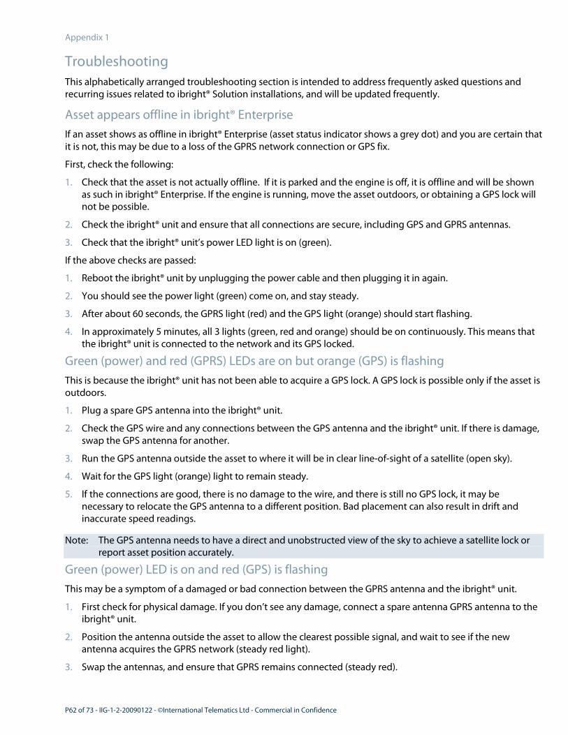
P62 of 73 - IIG-1-2-20090122 - ©International Telematics Ltd - Commercial in Confidence
Appendix 1
Troubleshooting
This alphabetically arranged troubleshooting section is intended to address frequently asked questions and
recurring issues related to ibright® Solution installations, and will be updated frequently.
Asset appears offline in ibright® Enterprise
If an asset shows as offline in ibright® Enterprise (asset status indicator shows a grey dot) and you are certain that
it is not, this may be due to a loss of the GPRS network connection or GPS fix.
First, check the following:
1. Check that the asset is not actually offline. If it is parked and the engine is off, it is offline and will be shown
as such in ibright® Enterprise. If the engine is running, move the asset outdoors, or obtaining a GPS lock will
not be possible.
2. Check the ibright® unit and ensure that all connections are secure, including GPS and GPRS antennas.
3. Check that the ibright® unit’s power LED light is on (green).
If the above checks are passed:
1. Reboot the ibright® unit by unplugging the power cable and then plugging it in again.
2. You should see the power light (green) come on, and stay steady.
3. After about 60 seconds, the GPRS light (red) and the GPS light (orange) should start flashing.
4. In approximately 5 minutes, all 3 lights (green, red and orange) should be on continuously. This means that
the ibright® unit is connected to the network and its GPS locked.
Green (power) and red (GPRS) LEDs are on but orange (GPS) is flashing
This is because the ibright® unit has not been able to acquire a GPS lock. A GPS lock is possible only if the asset is
outdoors.
1. Plug a spare GPS antenna into the ibright® unit.
2. Check the GPS wire and any connections between the GPS antenna and the ibright® unit. If there is damage,
swap the GPS antenna for another.
3. Run the GPS antenna outside the asset to where it will be in clear line-of-sight of a satellite (open sky).
4. Wait for the GPS light (orange) light to remain steady.
5. If the connections are good, there is no damage to the wire, and there is still no GPS lock, it may be
necessary to relocate the GPS antenna to a different position. Bad placement can also result in drift and
inaccurate speed readings.
Note: The GPS antenna needs to have a direct and unobstructed view of the sky to achieve a satellite lock or
report asset position accurately.
Green (power) LED is on and red (GPS) is flashing
This may be a symptom of a damaged or bad connection between the GPRS antenna and the ibright® unit.
1. First check for physical damage. If you don’t see any damage, connect a spare antenna GPRS antenna to the
ibright® unit.
2. Position the antenna outside the asset to allow the clearest possible signal, and wait to see if the new
antenna acquires the GPRS network (steady red light).
3. Swap the antennas, and ensure that GPRS remains connected (steady red).

IIG-1-2-20090122 ©International Telematics Ltd - Commercial in Confidence - P63 of 73
LEDs are all off on ibright® unit
This is a power supply issue.
1. The power supply cable to the ibright® unit must be traced back to where it is tapped into the power supply.
2. Test it with a multimeter to ensure that it receives at least 12V of power. The red wire is the constant 12V.
The white requires at least 6V, and needs to be tapped into the trucks true ignition. The black wire is the
ground.
3. After checking the power supply, power up the AutoTap first, and then the ibright® unit. The green power
light should be steady on the Autotap. If the green light blinks every 2 seconds on the ibright® unit, the
ignition is on. If the green light blinks rapidly, please contact us (see "Contact Information" on page 8), as this
means that there is a configuration issue with the unit.
Odometer reading not present in ibright® Enterprise
The reason for this is a faulty connection with the engine diagnostic system.
1. Power down the Autotap.
2. Power down the ibright® unit.
3. Check the wiring/plug into the J-BUS for damage, and make sure that the plug has not popped out.
4. Make sure that the pins are not disconnected from the junction plugs.
5. After checking all the above connections to satisfaction, power up the Autotap.
6. Power up the ibright® unit.
You should now see odometer readings coming through in ibright® Enterprise.

P64 of 73 - IIG-1-2-20090122 - ©International Telematics Ltd - Commercial in Confidence
Appendix 2
Wire Loom Parts and Ordering Codes
A typical installation will not usually require these parts as they are supplied with the pre-wired looms.
The table below is for the purpose of ordering individual parts to make up or repair looms as required.
Use the appropriate code to order the parts.
• New Zealand supplier: Tyco Electronics.
• United States supplier: Digikey Inc.
AMP Mini-Universal MATE-N-LOK
Description Units Type TYCO p/n DIGIKEY p/n
4 Circuit Plug 1 White
Natural
172167-1
172338-1
A25571-ND
-
Socket Contact, Gold,
22-18 AWG
4 Loose, 30µAu
Strip, 30µAu
1-770988-0
1-770904-0
A32016-ND
-
Hand Crimping Tool - - 91522-1 A9916-ND
Contact Extraction
Tool
- - 189727-1 A25695-ND
AMP Micro MATE-N-LOK
Description Units Type TYCO p/n DIGIKEY p/n
20 Circuit Receptacle
Housing
1 Black 2-794617-0 A30302-ND
18 Circuit Receptacle
Housing
1 Black 1-794617-8 A30301-ND
Receptacle Contacts,
Gold, 20-24 AWG
38 Loose, 15µAu
Loose, 30µAu
Strip, 15µAu
Strip, 30µAu
1-794610-1
1-794610-2
1-794606-1
1-794606-2
-
A32523-ND
-
-
Hand Crimping Tool - - 91501-1 A30498-ND
Contact Extraction
Tool
- - 843996-6 -

IIG-1-2-20090122 ©International Telematics Ltd - Commercial in Confidence - P65 of 73
Appendix 3
Resources
A number of additional resources are available for installers.
• If you experience problems not covered in this guide, feel free to contact us (see "Contact Information" on
page 8).
• If you have been set up with an installer login to Support Suite, you can use an online form
(http://support.itelematic.com) to raise a ticket for installation issues.
• Additional Wiring Diagrams are available in Support Suite.

P66 of 73 - IIG-1-2-20090122 - ©International Telematics Ltd - Commercial in Confidence
Appendix 4
J-Bus Plug Location Reference
This topic shows the location of the J-Bus connector in a number of assets.
Asset Plug Location Protocol Wiring Details
Freightliner,
Newer
Models
Beside door and left
seat
J1587 Yellow = Power and Ground
Orange = J1587 -
Green = J1587 +
Wires are usually labelled
Freightliner,
Older
Models
Passenger side
dashboard/fusebox
J1587 Yellow - all wires
Sterling,
2000
Left hand side wall,
behind door
J1587 Pink/Black = J1587 +
Pink/Green = J1587 -
Red/Black = Power
Black/Orange = GND
Power to plug is switched, don’t use
Sterling,
2003
onwards
Above clutch pedal J1587 Green = J1587 +
Orange = J1587 -
Red/Black = Power
Black/Orange = GND
Power to plug is switched, don’t use
International Relay box on
passenger side of
dash
J1587 Red/Pink = J1587 +
Blue = J1587 -
Purple/Grey = Power
White = GND
Power is switched, don't use
Mack, pre-
2007
Behind left hand seat J1587 White = all wires, except:
Black = GND
Has switched power as well, don’t use
Mack, late
model
Relay box on
passenger side
J1587 White = all wires
Power is switched, don’t use
Mack Vision Above brake pedal J1939 White = all wires
There is another connector above the clutch
pedal. Don’t use this.
Volvo Driver's side, under
dash
J1587 4-pin Plug
May be different in US models
Grey = J1587 +
Orange = J1587 -
Black = Power
White = GND
Power is switched, don’t use.

IIG-1-2-20090122 ©International Telematics Ltd - Commercial in Confidence - P67 of 73
Appendix 5
Wiring Overview Diagram


IIG-1-2-20090122 ©International Telematics Ltd - Commercial in Confidence - P69 of 73
Glossary G
Geofence
Geofences are 'virtual areas' defined within the
ibright® Solution that serve as checkpoints for asset
movements. By comparing the data from an asset
before, during and after an asset passes through a
Geofence, a comprehensive picture of an asset's
visit to a certain location or area can be obtained.
H
Hubo / Virtual Hubo
The popular abbreviation of the term hubodometer,
a mechanical device that measures distance
travelled in kilometers or miles (depending on the
country of use). It is attached to the wheel of an
asset, and is used mainly to estimate RUC charges.
International Telematics has developed proprietary
'virtual hubo' technology that estimates
hubodometer readings from odometer data, and is
a good reference check against the actual
hubodometer reading.
I
ibright® D-Series Unit
This compact communications unit is sometimes
required for specific asset installation situations, in
addition to the ibright® X-Series unit (see below).
The use of a D-series unit is extremely rare, and is
not covered in this guide.
ibright® Enterprise Software
The user interface and software application in which
you can work with the telematic information
generated by assets using the ibright® Solution.
ibright® X-Series Unit
The compact telematic computing and
communications unit that is the heart of the
ibright® Solution. It is installed in every asset, and
transmits OBD-II, SAE J1587 and SAE J1939
diagnostic data and GPS location information to the
International Telematics Servers when the asset is
active.
IFTA
International Fuel Tax Agreement. An agreement
between the lower 48 states of the United States
and the Canadian provinces to simplify the
reporting of fuel use by freight carriers that operate
in multiple jurisdictions.
J
J1587
SAE J1587 is a diagnostic data standard used on
older assets (for example, older trucks and heavy
vehicles).
J1939
SAE J1939 is a diagnostic data standard. Most
modern assets (for example, trucks and heavy
vehicles) use this standard.
J-Bus
The generic term for diagnostic bus connector
plugs or sockets using any SAE J standard protocol
(see J1587, J1939 below).
M
MDT
Mobile Data Terminal, a compact computer that
may either be plugged into the ibright® unit to view
and analyze stored telematic information, or
installed in an asset to show that information or
enable communications between an office base and
an asset operator.
MECP
Mobile Electronic Certified Professional, a
certification for mobile electronics installation
technicians.
N
NZTA
New Zealand Transport Agency. In the context of
land transport policy initiatives, directives and
documents, NZTA is now synonymous with Land
Transport New Zealand (LTNZ) and Land Transport
Safety Authority (LTSA). It is responsible, among
other things, for administering road infrastructure
maintenance and revenue from road users like RUC
(see below).

P70 of 73 - IIG-1-2-20090122 - ©International Telematics Ltd - Commercial in Confidence
O
OBD, OBD-II
On-Board Diagnostics, a protocol developed by
General Motors in the mid 1980s used in the
capture of diagnostic information from assets. OBD-
II is the latest version of the protocol, and is
equivalent to SAE J1979. This standard is mainly
used in cars.
P
PLC
Power Line Communication, the technology that
allows data to be exchanged over power lines. In
fleet asset management, PLC technology allows
drivers to monitor the status of trailers. For the
ibright® Solution a PLC Reader is linked to the
ibright® unit, and communicates with a PLC ID unit
in the trailer.
PTO
Power Take-Off, a mechanical link provided on
tractor assets to allow farm equipment, for example,
to be driven by the tractor.
R
Reefer
The popular term for a refrigerated unit.
RUC
Road User Charges, a New Zealand specific levy on
heavy vehicles and specialized vehicles that are not
taxed at the source, to allow them to operate on
public roads. RUC is administered by NZTA (see
above).
S
Smart Beaconing
An ibright® Solution technology that reports GPS
position data only when an asset changes direction
of travel, not at specified time intervals, ensuring
that the data is meaningful and accurate.

IIG-1-2-20090122 ©International Telematics Ltd - Commercial in Confidence - P71 of 73
Index
1
18 Way Loom • 23
2
20 Way Loom • 22
6
6/9 Pin J-Bus Y Cable • 22
6-Pin J-Bus Connector • 30
9
9-Pin J-Bus Connector • 31
A
Access Tools and Equipment • 17
Appendices • 61
Assemble Tools and Components • 34
Asset appears offline in ibright® Enterprise • 62
Asset Warranty Conditions • 14
AutoTap • 23
AutoTap Installation • 49
B
Basic Kit Box • 18
Blade Fuse Holder • 19
Blade Fuse, 5 Amp Plugin ATQ • 19
Bluetooth Coverage Area • 32
Bracket Preparation • 52
C
Cable Tie • 21
Camera • 16
Certification and Compliance Requirements for
Installers - US • 11
Connectivity Options • 32
Contact Information • 8
Copyright Notice and Disclaimer • 6
D
Dallas ID • 55
Drilling and Cutting Precautions • 15
E
External Antenna Installation • 46
External Combo Antenna (US Only) • 25
External GPS Antenna • 24
External GSM Antenna (US Only) • 24
External GSM Stub Antenna (NZ Only) • 24
F
Federal Communications Commission Statement • 7
Final Unit Mounting • 58
For more information, please contact: • 8
For Whom is this Guide? • 10
G
General Installation Considerations • 14
Geofence • 69
Getting Help • 9
Green (power) and red (GPRS) LEDs are on but
orange (GPS) is flashing • 62
Green (power) LED is on and red (GPS) is flashing •
62
Ground (Earth) Wiring • 47
H
Hardware Components • 18
Health and Safety Precautions • 14
How Does the ibright® Solution Work? • 12
Hubo / Virtual Hubo • 69

P72 of 73 - IIG-1-2-20090122 - ©International Telematics Ltd - Commercial in Confidence
I
ibright® D-Series Unit • 69
ibright® Enterprise Software • 69
ibright® Mounting Tools • 17
ibright® X-Series 18 Pin Port • 28
ibright® X-Series 20 Pin Port • 29
ibright® X-Series Mounting Bracket • 20
ibright® X-Series Ports - Overview • 28
ibright® X-Series Unit • 18, 69
ibright® X-Series Unit Wiring • 51
IFTA • 69
Incorrect ibright® unit Position • 36, 51
Installation • 42
Installation and Work Repair Form (IWRF) • 16
Installation Documentation • 16
Internal Antennas • 32
International Telematics' Expectations • 10
IWRF (Installation and Work Repair Form) • 16
J
J1587 • 69
J1939 • 69
J-Bus • 69
J-Bus Connection • 48
J-Bus Plug Location Reference • 66
L
LEDs are all off on ibright® unit • 63
M
Major Installations • 13
Making Connections, Port Protection • 56
MDT • 69
MDT (Mobile Data Terminal) • 26
MDT Installation • 54
MECP • 69
MECP Certification (US) • 11
Mounting Screws • 20
N
NZTA • 69
O
OBD, OBD-II • 70
Odometer reading not present in ibright® Enterprise
• 63
Optional Components • 22
Overview • 10
P
Pilot Installations • 13
Planning and Coordinating Installations • 13
PLC • 70
Ports and Connections • 28
Post Installation • 59
Post-install Testing • 59
Power Loom with Inline Fuse • 19
Power Wiring • 50
Pre-Installation Checks • 34
Pre-Installation Electrical Checks • 34
PTO • 70
R
RAM Mounting Bracket for MDT • 26
Reefer • 70
Resources • 65
Roll-out Plan • 13
Rubber Port Protection Grommet • 20

IIG-1-2-20090122 ©International Telematics Ltd - Commercial in Confidence - P73 of 73
RUC • 70
S
Scope and Test Power Supply to ibright® Unit /
Autotap • 35
Scope Dallas ID Tag / Reader Location • 41
Scope External Antenna Locations • 39
Scope Fusebox Location • 35
Scope Ground (Earth) Point • 35
Scope ibright® Unit Location and Position • 36
Scope J-Bus Plug Location • 36
Scope MDT Location • 40
Scope PLC Reader / PLC ID Positions and Wiring • 40
Scope Protocols • 35
Scope True Ignition, Cable Path • 35
Security Stickers • 21
SIM Card Installation • 44
Smart Beaconing • 70
Status Indicators and Status Testing • 57
T
Thermoking iBox Sensor • 25
Things to Remember when Installing • 43
Tools and Equipment • 17
Troubleshooting • 62
W
Wire Loom Parts and Ordering Codes • 64
Wiring Overview Diagram • 67
Wiring Tools and Accessories • 17