IBM Half High LTO Ultrium Gen 6 Internal SAS Tape Drive ...
118
IBM Half High LTO Ultrium Gen 6 Internal SAS Tape Drive Installation and User's Guide
Transcript of IBM Half High LTO Ultrium Gen 6 Internal SAS Tape Drive ...

IBM Half High LTO Ultrium Gen 6 Internal SAS Tape Drive
Installation and User's Guide
���


IBM Half High LTO Ultrium Gen 6 Internal SAS Tape Drive
Installation and User's Guide
���

Note: Before using this information and the product it supports, read the general information in“Notices” on page 77 and the IBM Safety Information, and IBM Environmental Notices and User'sGuide on the IBM Documentation CD, and the IBM Warranty Information document that comes withthe system.
Second Edition (June 2013)
© Copyright IBM Corporation 2013.US Government Users Restricted Rights – Use, duplication or disclosure restricted by GSA ADP Schedule Contractwith IBM Corp.
Contents
Figures . . . . . . . . . . . . . . . v
Tables . . . . . . . . . . . . . . . vii
Safety . . . . . . . . . . . . . . . ixGuidelines for trained service technicians . . . . . x
Inspecting for unsafe conditions . . . . . . . xGuidelines for servicing electrical equipment . . xi
Safety statements . . . . . . . . . . . . xii
Chapter 1. Introduction . . . . . . . . 1Drive features . . . . . . . . . . . . . . 1Front panel of the drive . . . . . . . . . . 2Rear panel of the drive . . . . . . . . . . . 2Drive performance . . . . . . . . . . . . 3Cartridge compatibility . . . . . . . . . . . 3Speed matching . . . . . . . . . . . . . 4Channel calibration . . . . . . . . . . . . 5Data cartridge capacity scaling . . . . . . . . 5Encryption . . . . . . . . . . . . . . . 5Inhibit firmware down-leveling . . . . . . . . 5SAS interface . . . . . . . . . . . . . . 5Supported Servers and Operating Systems . . . . 6Supported device drivers . . . . . . . . . . 6Ethernet port . . . . . . . . . . . . . . 6Linear Tape File System (LTFS) . . . . . . . . 6
Chapter 2. Tape drive installation . . . . 9Installation guidelines . . . . . . . . . . . 9Handling static-sensitive devices. . . . . . . . 9Inventory checklist . . . . . . . . . . . . 10Installing a tape drive . . . . . . . . . . . 10
Unpacking the drive . . . . . . . . . . 10Acclimating the drive and media . . . . . . 11Turning off the enclosure or server . . . . . 11Setting the feature switches . . . . . . . . 11Mounting the drive in an enclosure or server . . 12Connecting and testing power to the drive . . . 12Connecting the cable . . . . . . . . . . 13Running drive diagnostics . . . . . . . . 13Installing device drivers . . . . . . . . . 13Connecting the external interface cable (enclosureor server installations only) . . . . . . . . 14Configuring the drive to the server, switch, orhub . . . . . . . . . . . . . . . . 14
Updating firmware . . . . . . . . . . . . 14Registering for My Support . . . . . . . . . 15
Chapter 3. Operating the drive . . . . 17Operating modes . . . . . . . . . . . . 17Power button . . . . . . . . . . . . . . 17Single-character display (SCD) . . . . . . . . 17Status lights . . . . . . . . . . . . . . 18Unload button . . . . . . . . . . . . . 21
Inserting a tape cartridge . . . . . . . . . . 22Removing a tape cartridge . . . . . . . . . 23Mid-tape recovery . . . . . . . . . . . . 23Cleaning the drive head . . . . . . . . . . 23Cleaning the tape drive . . . . . . . . . . 24Tape drive status web page . . . . . . . . . 24Diagnostic and maintenance functions . . . . . 25
Entering Maintenance mode . . . . . . . . 27Exiting Maintenance mode . . . . . . . . 27Function code 0: Maintenance mode . . . . . 28Function code 1: Run drive diagnostics . . . . 28Function code 2: Update drive firmware fromFMR tape . . . . . . . . . . . . . . 29Function code 3: Create FMR tape . . . . . . 30Function code 4: Force a drive dump . . . . . 30Function code 5: Copy drive dump . . . . . 31Function code 6: Run host interface wrap test . . 32Function code 7: Run RS-422 wrap test . . . . 33Function code 8: Unmake FMR tape . . . . . 33Function code 9: Display error code log . . . . 34Function code A: Clear error code log . . . . 34Function code C: Insert cartridge into tape drive 35Function code E: Test cartridge and media . . . 35Function code F: Write performance test . . . . 36Function code H: Test head . . . . . . . . 37Function code J: Fast read/write test . . . . . 38Function code L: Load/unload test . . . . . 39Function code P: Enable post error reporting . . 39Function code U: Disable post error reporting . . 40
Tape drive diagnostic and maintenance web page 40
Chapter 4. Using Ultrium media . . . . 43Types of cartridges . . . . . . . . . . . . 44
Data cartridge . . . . . . . . . . . . 44WORM (Write Once, Read Many) cartridge. . . 45Cleaning cartridge . . . . . . . . . . . 47
Cartridge compatibility . . . . . . . . . . 47Handling cartridges . . . . . . . . . . . 47
Provide training . . . . . . . . . . . . 48Provide proper acclimation and environmentalconditions . . . . . . . . . . . . . . 48Inspect the cartridge . . . . . . . . . . 48Handle the cartridge carefully . . . . . . . 48Tape cartridge packaging . . . . . . . . . 49
Environmental and shipping specifications for tapecartridges . . . . . . . . . . . . . . . 50Disposing of tape cartridges . . . . . . . . . 51
Chapter 5. Resolving problems . . . . 53Procedure 1: Inspecting a cartridge for damage . . 53Procedure 2: Checking SAS host connections . . . 54Procedure 3: Verifying host interface communication 54Resolving problems reported by the server . . . . 55Resolving problems with the tape media . . . . 55Replacing the tape drive . . . . . . . . . . 56
© Copyright IBM Corp. 2013 iii

Appendix A. Getting help and technicalassistance . . . . . . . . . . . . . 57Before you call . . . . . . . . . . . . . 57Using the documentation . . . . . . . . . . 58Getting help and information from the World WideWeb . . . . . . . . . . . . . . . . . 58How to send DSA data to IBM . . . . . . . . 58Creating a personalized support web page . . . . 58Software service and support . . . . . . . . 58Hardware service and support . . . . . . . . 59IBM Taiwan product service . . . . . . . . . 59
Appendix B. TapeAlert flags . . . . . 61
Appendix C. Error codes andmessages . . . . . . . . . . . . . 63
Appendix D. Repairing a cartridge . . . 69Examples of cartridge problems . . . . . . . 69Repositioning a leader pin . . . . . . . . . 69Reattaching a leader pin . . . . . . . . . . 71
Notices . . . . . . . . . . . . . . 77Trademarks . . . . . . . . . . . . . . 77Important notes . . . . . . . . . . . . . 78Particulate contamination. . . . . . . . . . 79
Documentation format. . . . . . . . . . . 80Telecommunication regulatory statement . . . . 80Electronic emission notices . . . . . . . . . 80
Federal Communications Commission (FCC)statement . . . . . . . . . . . . . . 80Industry Canada Class A emission compliancestatement . . . . . . . . . . . . . . 81Avis de conformité à la réglementationd'Industrie Canada . . . . . . . . . . . 81Australia and New Zealand Class A statement . 81European Union EMC Directive conformancestatement . . . . . . . . . . . . . . 81Germany Class A statement . . . . . . . . 82Japan VCCI Class A statement . . . . . . . 83Japan Electronics and Information TechnologyIndustries Association (JEITA) statement. . . . 83Korea Communications Commission (KCC)statement . . . . . . . . . . . . . . 83Russia Electromagnetic Interference (EMI) ClassA statement . . . . . . . . . . . . . 83People's Republic of China Class A electronicemission statement . . . . . . . . . . . 84Taiwan Class A compliance statement . . . . 84
Glossary . . . . . . . . . . . . . . 85
Index . . . . . . . . . . . . . . . 95
iv IBM Half High LTO Ultrium Gen 6 Internal SAS Tape Drive: Installation and User's Guide

Figures
1. View of a tape drive . . . . . . . . . . 12. Tape drive front panel element descriptions 23. Tape drive rear panel element descriptions 24. Inserting a cartridge into the drive . . . . . 225. Drive status web page . . . . . . . . . 246. Drive status web page - Topic details . . . . 257. Tape drive diagnostic page . . . . . . . 418. The IBM LTO Ultrium Data Cartridge. . . . 439. Ultrium data cartridge on the left; WORM
cartridge on the right . . . . . . . . . 4610. Tape cartridges in a Turtlecase . . . . . . 4911. Double-boxing tape cartridges for shipping 50
12. Flowchart for analyzing maintenance problems 5313. Leader pin in the incorrect and correct
positions . . . . . . . . . . . . . 7014. Placing the dislodged leader pin into the
correct position . . . . . . . . . . . 7015. Rewinding the tape into the cartridge . . . . 7116. Leader Pin Reattachment Kit . . . . . . . 7217. Attaching the leader pin attach tool to the
cartridge . . . . . . . . . . . . . 7318. Winding the tape out of the cartridge . . . . 7419. Removing the C-clip from the leader pin 7420. Attaching the leader pin to the tape . . . . 75
© Copyright IBM Corp. 2013 v

vi IBM Half High LTO Ultrium Gen 6 Internal SAS Tape Drive: Installation and User's Guide

Tables
1. CRU and Option part numbers . . . . . . 12. Performance rates and times . . . . . . . 33. Ultrium cartridge compatibility with Ultrium
tape drives . . . . . . . . . . . . . 34. Performance parameters. . . . . . . . . 45. Feature switch definitions . . . . . . . . 116. Meaning of status lights and single-character
display (SCD) . . . . . . . . . . . . 197. Functions that the Unload button performs 21
8. Diagnostic and maintenance functions . . . 269. Ultrium cartridge compatibility with Ultrium
tape drives . . . . . . . . . . . . . 4710. Environment for operating, storing, and
shipping LTO media . . . . . . . . . 5011. CRU and Option part numbers . . . . . . 5612. Error codes on the SCD . . . . . . . . 6313. Limits for particulates and gases . . . . . 79
© Copyright IBM Corp. 2013 vii

viii IBM Half High LTO Ultrium Gen 6 Internal SAS Tape Drive: Installation and User's Guide

Safety
Before installing this product, read the Safety Information.
Antes de instalar este produto, leia as Informações de Segurança.
Læs sikkerhedsforskrifterne, før du installerer dette produkt.
Lees voordat u dit product installeert eerst de veiligheidsvoorschriften.
Ennen kuin asennat tämän tuotteen, lue turvaohjeet kohdasta Safety Information.
Avant d'installer ce produit, lisez les consignes de sécurité.
Vor der Installation dieses Produkts die Sicherheitshinweise lesen.
Prima di installare questo prodotto, leggere le Informazioni sulla Sicurezza.
© Copyright IBM Corp. 2013 ix

Les sikkerhetsinformasjonen (Safety Information) før du installerer dette produktet.
Antes de instalar este produto, leia as Informações sobre Segurança.
Antes de instalar este producto, lea la información de seguridad.
Läs säkerhetsinformationen innan du installerar den här produkten.
Guidelines for trained service techniciansThis section contains information for trained service technicians.
Inspecting for unsafe conditionsUse this information to help you identify potential unsafe conditions in an IBM®
product that you are working on.
Each IBM product, as it was designed and manufactured, has required safety itemsto protect users and service technicians from injury. The information in this sectionaddresses only those items. Use good judgment to identify potential unsafeconditions that might be caused by non-IBM alterations or attachment of non-IBMfeatures or optional devices that are not addressed in this section. If you identify
x IBM Half High LTO Ultrium Gen 6 Internal SAS Tape Drive: Installation and User's Guide

an unsafe condition, you must determine how serious the hazard is and whetheryou must correct the problem before you work on the product.
Consider the following conditions and the safety hazards that they present:v Electrical hazards, especially primary power. Primary voltage on the frame can
cause serious or fatal electrical shock.v Explosive hazards, such as a damaged CRT face or a bulging capacitor.v Mechanical hazards, such as loose or missing hardware.
To inspect the product for potential unsafe conditions, complete the followingsteps:1. Make sure that the power is off and the power cords are disconnected.2. Make sure that the exterior cover is not damaged, loose, or broken, and observe
any sharp edges.3. Check the power cords:
v Make sure that the third-wire ground connector is in good condition. Use ameter to measure third-wire ground continuity for 0.1 ohm or less betweenthe external ground pin and the frame ground.
v Make sure that the power cords are the correct type.v Make sure that the insulation is not frayed or worn.
4. Remove the cover.5. Check for any obvious non-IBM alterations. Use good judgment as to the safety
of any non-IBM alterations.6. Check inside the system for any obvious unsafe conditions, such as metal
filings, contamination, water or other liquid, or signs of fire or smoke damage.7. Check for worn, frayed, or pinched cables.8. Make sure that the power-supply cover fasteners (screws or rivets) have not
been removed or tampered with.
Guidelines for servicing electrical equipmentObserve these guidelines when you service electrical equipment.v Check the area for electrical hazards such as moist floors, nongrounded power
extension cords, and missing safety grounds.v Use only approved tools and test equipment. Some hand tools have handles that
are covered with a soft material that does not provide insulation from liveelectrical current.
v Regularly inspect and maintain your electrical hand tools for safe operationalcondition. Do not use worn or broken tools or testers.
v Do not touch the reflective surface of a dental mirror to a live electrical circuit.The surface is conductive and can cause personal injury or equipment damage ifit touches a live electrical circuit.
v Some rubber floor mats contain small conductive fibers to decrease electrostaticdischarge. Do not use this type of mat to protect yourself from electrical shock.
v Do not work alone under hazardous conditions or near equipment that hashazardous voltages.
v Locate the emergency power-off (EPO) switch, disconnecting switch, or electricaloutlet so that you can turn off the power quickly in the event of an electricalaccident.
v Disconnect all power before you perform a mechanical inspection, work nearpower supplies, or remove or install main units.
Safety xi

v Before you work on the equipment, disconnect the power cord. If you cannotdisconnect the power cord, have the customer power-off the wall box thatsupplies power to the equipment and lock the wall box in the off position.
v Never assume that power has been disconnected from a circuit. Check it tomake sure that it has been disconnected.
v If you have to work on equipment that has exposed electrical circuits, observethe following precautions:– Make sure that another person who is familiar with the power-off controls is
near you and is available to turn off the power if necessary.– When you work with powered-on electrical equipment, use only one hand.
Keep the other hand in your pocket or behind your back to avoid creating acomplete circuit that could cause an electrical shock.
– When you use a tester, set the controls correctly and use the approved probeleads and accessories for that tester.
– Stand on a suitable rubber mat to insulate you from grounds such as metalfloor strips and equipment frames.
v Use extreme care when you measure high voltages.v To ensure proper grounding of components such as power supplies, pumps,
blowers, fans, and motor generators, do not service these components outside oftheir normal operating locations.
v If an electrical accident occurs, use caution, turn off the power, and send anotherperson to get medical aid.
Safety statementsThese statements provide the caution and danger information that is used in thisdocumentation.
Important:
Each caution and danger statement in this documentation is labeled with anumber. This number is used to cross reference an English-language caution ordanger statement with translated versions of the caution or danger statement inthe Safety Information document.
For example, if a caution statement is labeled “Statement 1,” translations for thatcaution statement are in the Safety Information document under “Statement 1.”
Be sure to read all caution and danger statements in this documentation before youperform the procedures. Read any additional safety information that comes withyour system or optional device before you install the device.
Statement 1
xii IBM Half High LTO Ultrium Gen 6 Internal SAS Tape Drive: Installation and User's Guide
DANGER
Electrical current from power, telephone, and communication cables ishazardous.
To avoid a shock hazard:
v Do not connect or disconnect any cables or perform installation,maintenance, or reconfiguration of this product during an electrical storm.
v Connect all power cords to a properly wired and grounded electrical outlet.
v Connect to properly wired outlets any equipment that will be attached tothis product.
v When possible, use one hand only to connect or disconnect signal cables.
v Never turn on any equipment when there is evidence of fire, water, orstructural damage.
v Disconnect the attached power cords, telecommunications systems,networks, and modems before you open the device covers, unlessinstructed otherwise in the installation and configuration procedures.
v Connect and disconnect cables as described in the following table wheninstalling, moving, or opening covers on this product or attached devices.
To Connect: To Disconnect:
1. Turn everything OFF.
2. First, attach all cables to devices.
3. Attach signal cables to connectors.
4. Attach power cords to outlet.
5. Turn device ON.
1. Turn everything OFF.
2. First, remove power cords from outlet.
3. Remove signal cables from connectors.
4. Remove all cables from devices.
Statement 3
CAUTION:When laser products (such as CD-ROMs, DVD drives, fiber optic devices, ortransmitters) are installed, note the following:
v Do not remove the covers. Removing the covers of the laser product couldresult in exposure to hazardous laser radiation. There are no serviceable partsinside the device.
v Use of controls or adjustments or performance of procedures other than thosespecified herein might result in hazardous radiation exposure.
Safety xiii

DANGER
Some laser products contain an embedded Class 3A or Class 3B laser diode.Note the following.
Laser radiation when open. Do not stare into the beam, do not view directlywith optical instruments, and avoid direct exposure to the beam.
Statement 5
CAUTION:The power control button on the device and the power switch on the powersupply do not turn off the electrical current supplied to the device. The devicealso might have more than one power cord. To remove all electrical current fromthe device, ensure that all power cords are disconnected from the power source.
Statement 8
xiv IBM Half High LTO Ultrium Gen 6 Internal SAS Tape Drive: Installation and User's Guide

CAUTION:Never remove the cover on a power supply or any part that has the followinglabel attached.
Hazardous voltage, current, and energy levels are present inside any componentthat has this label attached. There are no serviceable parts inside thesecomponents. If you suspect a problem with one of these parts, contact a servicetechnician.
Safety xv

xvi IBM Half High LTO Ultrium Gen 6 Internal SAS Tape Drive: Installation and User's Guide
Chapter 1. Introduction
The product description of the IBM Half High LTO Ultrium Gen 6 Internal SASTape Drive.
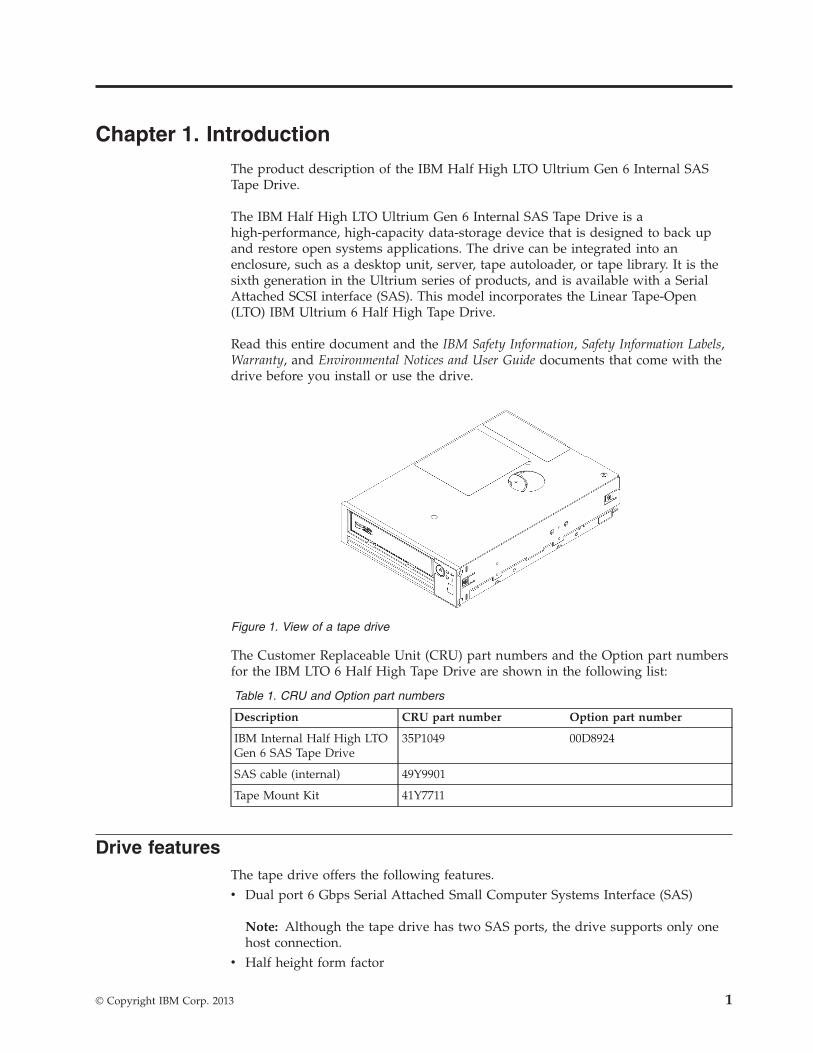
The IBM Half High LTO Ultrium Gen 6 Internal SAS Tape Drive is ahigh-performance, high-capacity data-storage device that is designed to back upand restore open systems applications. The drive can be integrated into anenclosure, such as a desktop unit, server, tape autoloader, or tape library. It is thesixth generation in the Ultrium series of products, and is available with a SerialAttached SCSI interface (SAS). This model incorporates the Linear Tape-Open(LTO) IBM Ultrium 6 Half High Tape Drive.
Read this entire document and the IBM Safety Information, Safety Information Labels,Warranty, and Environmental Notices and User Guide documents that come with thedrive before you install or use the drive.
The Customer Replaceable Unit (CRU) part numbers and the Option part numbersfor the IBM LTO 6 Half High Tape Drive are shown in the following list:
Table 1. CRU and Option part numbers
Description CRU part number Option part number
IBM Internal Half High LTOGen 6 SAS Tape Drive
35P1049 00D8924
SAS cable (internal) 49Y9901
Tape Mount Kit 41Y7711
Drive featuresThe tape drive offers the following features.v Dual port 6 Gbps Serial Attached Small Computer Systems Interface (SAS)
Note: Although the tape drive has two SAS ports, the drive supports only onehost connection.
v Half height form factor
Figure 1. View of a tape drive
© Copyright IBM Corp. 2013 1

v Native storage capacity of 2500 GB (2.5 TB) per cartridge (6250 GB at 2.5:1compression)
v Maximum native data transfer rate of up to 160 MB per secondv Burst data transfer rate of 600 MB per secondv 512 MB read-and-write cachev Support for encryption on Ultrium 5 and Ultrium 6 tape cartridgesv Single Character Display (SCD) operator panelv Ready, Fault, and Encryption status lightsv Maintenance Mode functionsv Support for WORM (Write Once Read Many) on WORM cartridge types
Front panel of the driveThe tape drive front panel's elements descriptions.
Rear panel of the driveThe tape drive rear panel's elements descriptions.
Figure 2. Tape drive front panel element descriptions
SAS and powercable connector
Fan
Figure 3. Tape drive rear panel element descriptions
2 IBM Half High LTO Ultrium Gen 6 Internal SAS Tape Drive: Installation and User's Guide
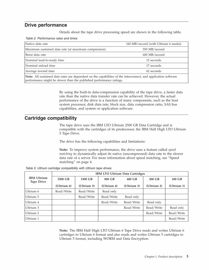
Drive performanceDetails about the tape drive processing speed are shown in the following table.
Table 2. Performance rates and times
Native data rate 160 MB/second (with Ultrium 6 media)
Maximum sustained data rate (at maximum compression) 550 MB/second
Burst data rate 600 MB/second
Nominal load-to-ready time 12 seconds
Nominal unload time 17 seconds
Average rewind time 62 seconds
Note: All sustained data rates are dependent on the capabilities of the interconnect, and application softwareperformance might be slower than the published performance ratings.
By using the built-in data-compression capability of the tape drive, a faster datarate than the native data transfer rate can be achieved. However, the actualperformance of the drive is a function of many components, such as the hostsystem processor, disk data rate, block size, data compression ratio, SAS buscapabilities, and system or application software.
Cartridge compatibilityThe tape drive uses the IBM LTO Ultrium 2500 GB Data Cartridge and iscompatible with the cartridges of its predecessor, the IBM Half High LTO Ultrium5 Tape Drive.
The drive has the following capabilities and limitations:
Note: To improve system performance, the drive uses a feature called speedmatching to dynamically adjust its native (uncompressed) data rate to the slowerdata rate of a server. For more information about speed matching, see “Speedmatching” on page 4.
Table 3. Ultrium cartridge compatibility with Ultrium tape drives
IBM UltriumTape Drive
IBM LTO Ultrium Data Cartridges
2500 GB
(Ultrium 6)
1500 GB
(Ultrium 5)
800 GB
(Ultrium 4)
400 GB
(Ultrium 3)
200 GB
(Ultrium 2)
100 GB
(Ultrium 1)
Ultrium 6 Read/Write Read/Write Read only
Ultrium 5 Read/Write Read/Write Read only
Ultrium 4 Read/Write Read/Write Read only
Ultrium 3 Read/Write Read/Write Read only
Ultrium 2 Read/Write Read/Write
Ultrium 1 Read/Write
Note: The IBM Half High LTO Ultrium 6 Tape Drive reads and writes Ultrium 6cartridges to Ultrium 6 format and also reads and writes Ultrium 5 cartridges toUltrium 5 format, including WORM and Data Encryption.
Chapter 1. Product description 3
The drive reads tapes that have been written by other licensed Ultrium 6 drives,and writes to tapes that can be read by other licensed Ultrium 6 drives.
In addition to using the IBM LTO Ultrium Data Cartridge with up to 2500 GBcapacity, the drive also offers read/write capability for certified LTO Ultrium tapecartridges.
Important: The IBM Half High LTO Ultrium 6 Tape Drive cartridge has a limitedone year warranty provided by IBM Storage Media. If any defect in material ormanufacture appears within one year of the date of original purchase of thisproduct, it will be replaced or the purchase price refunded. Please contact the sellerof the of IBM Data Storage products or visit us on the web at http://www-03.ibm.com/systems/storage/media/. Within the US and Canada, call toll free(888)426-6334 or (888)IBM-MEDIA) to receive warranty service or productinformation.
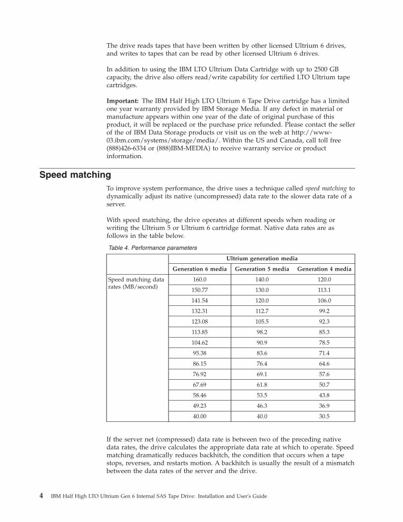
Speed matchingTo improve system performance, the drive uses a technique called speed matching todynamically adjust its native (uncompressed) data rate to the slower data rate of aserver.
With speed matching, the drive operates at different speeds when reading orwriting the Ultrium 5 or Ultrium 6 cartridge format. Native data rates are asfollows in the table below.
Table 4. Performance parameters
Ultrium generation media
Generation 6 media Generation 5 media Generation 4 media
Speed matching datarates (MB/second)
160.0 140.0 120.0
150.77 130.0 113.1
141.54 120.0 106.0
132.31 112.7 99.2
123.08 105.5 92.3
113.85 98.2 85.3
104.62 90.9 78.5
95.38 83.6 71.4
86.15 76.4 64.6
76.92 69.1 57.6
67.69 61.8 50.7
58.46 53.5 43.8
49.23 46.3 36.9
40.00 40.0 30.5
If the server net (compressed) data rate is between two of the preceding nativedata rates, the drive calculates the appropriate data rate at which to operate. Speedmatching dramatically reduces backhitch, the condition that occurs when a tapestops, reverses, and restarts motion. A backhitch is usually the result of a mismatchbetween the data rates of the server and the drive.
4 IBM Half High LTO Ultrium Gen 6 Internal SAS Tape Drive: Installation and User's Guide

Channel calibrationSystem performance is further optimized by a feature called Channel calibration, inwhich the drive automatically customizes each read/write data channel tocompensate for variations in such things as the recording channel's transferfunction, the media, and characteristics of the drive head.
Data cartridge capacity scalingThe SET CAPACITY SCSI command enables a customer to capacity scale a datacartridge to enable faster random access. For example, a user can capacity scale adata cartridge to 20% of its normal length which improves the average access timeby almost a factor of 5; however, it also reduces the native capacity of the tape to500 GB.
EncryptionThe IBM LTO 6 Half High Tape Drive supports host Application ManagedEncryption (AME), using T10 encryption methods.
However, encryption must be enabled through the software application that youuse to manage the tape drive. For more information about enabling encryption, seethe independent software vendor documentation that came with your software.
Data encryption is supported only with LTO Ultrium 4, LTO Ultrium 5, and LTOUltrium 6 data cartridges. The encryption-enabled drive contains the necessaryhardware and firmware to encrypt and decrypt host tape application data.Encryption policy and encryption keys are provided by the host application; thereis no encryption setup required for this drive. A drive digital certificate is installedat manufacturing time. Each drive has a unique serial number and certificate. TheT10 application might validate each drive instance by checking the drive's digitalcertificate.
Application-managed encryption is supported on AIX®, Windows Server, Linux®,and Solaris. Encryption requires the latest device drivers available on the IBMwebsite: http://www.ibm.com/support/fixcentral.
For more information, see the IBM Tape Device Drivers Encryption Support and IBMLTO Ultrium Tape Drive SCSI Reference documentation.
Inhibit firmware down-levelingThe drive provides the capability to prevent loading and installing drive microcodevia a Field Microcode Replace (FMR tape) if the firmware level contained in theFMR tape is older than the code level already installed. This option is controlledby the host application. No checking is performed if the firmware level is loadedvia the host interface or the library interface.
SAS interfaceThe drive has a dual-port 6 Gbps SAS (Serial Attached SCSI) host interface, butonly one of the SAS ports is used for a host connection.
Important: The tape drive supports only one host connection.
Chapter 1. Product description 5
A drive with a SAS interface can be linked directly to controllers. SAS is aperformance improvement over traditional SCSI because SAS enables multipledevices (up to 128) of different sizes and types to be connected simultaneouslywith thinner and longer cables; its full-duplex signal transmission supports 6.0 Gbper second. SAS drives can be hot-plugged.
SAS drives will auto-negotiate speed. There are no configurable topologies, andtherefore no feature switches associated with SAS.
Supported Servers and Operating SystemsThe latest supported attachments.
To determine the latest supported attachments, visit the IBM ServerProven websitefor System x Tape Backup Units: http://www-03.ibm.com/servers/eserver/serverproven/compat/us/xseries/storage/tmatrix.html.
For specific instructions about attaching the drive, see Chapter 2, “Tape driveinstallation,” on page 9.
Supported device driversGetting the supported device drivers for the tape drive.
To download the latest device drivers, go to http://www-947.ibm.com/support/entry/portal/, and complete the following steps.
Note: Changes are made periodically to the IBM website. The actual proceduremight vary slightly from what is described in this document.1. Go to http://www-947.ibm.com/support/entry/portal/.2. In the Search support & downloads text field at the top right hand corner of
the screen, type tape files and press Enter.3. In the list of search results, click the link Tape Files (index) - Software for tape
drives and libraries.
Ethernet portThe IBM LTO 6 Half High Tape Drive has a single 1 Gbps Ethernet port on therear panel, with a RJ45 connector.
The default IP address is 169.254.0.3, but the drive’s IP address can be changed asneeded. Refer to the IBM Tape Diagnostic Tool from the http://www-947.ibm.com/support/entry/portal/ website on how to make this change.
The Ethernet port is used only for monitoring drive status and servicing the drive,not for data transmission.
Linear Tape File System (LTFS)The Linear Tape File System (LTFS) is a file system that works in conjunction withLTO Generation tape technology to access data stored on an IBM tape cartridge.
LTFS uses the file system’s format and resources of the operating system (OS) onwhich it is running to graphically display the contents of a tape cartridge in theOS’s graphical user interface (GUI) format; typically a folder/tree structure. Using
6 IBM Half High LTO Ultrium Gen 6 Internal SAS Tape Drive: Installation and User's Guide

the host operating system’s graphical file manager, reading data on a LTO tapecartridge is as easy as dragging and dropping. Users can run any applicationdesigned for disk files against tape data without concern for the fact that the datais physically stored on tape.
Chapter 1. Product description 7

8 IBM Half High LTO Ultrium Gen 6 Internal SAS Tape Drive: Installation and User's Guide
Chapter 2. Tape drive installation
This chapter describes the installation procedures for the tape drive. It is thecustomer's responsibility to install this product.
This is a customer setup unit. It is the customer's responsibility to install thisproduct.
Depending on the type of enclosure or server, installation procedures might vary.Refer to the enclosure or server documentation for drive installation. The followinggeneric procedures can be used if the enclosure or server documentation is notavailable:v “Installing a tape drive” on page 10
Note: Before you install the tape drive, read the information in the followingsections:v “Installation guidelines”v “Handling static-sensitive devices”v “Inventory checklist” on page 10
Installation guidelinesBefore you remove or replace a device, read the following safety information.v Read the safety information in “Safety” on page ix. This information will help
you work safely. Take standard electrostatic discharge precautions when youwork inside the server.
v Observe good housekeeping in the area where you are working. Place removedcovers and other parts in a safe place.
v Do not attempt to lift an object that you think is too heavy for you. If you haveto lift a heavy object, observe the following precautions:– Make sure that you can stand safely without slipping.– Distribute the weight of the object equally between your feet.– Use a slow lifting force. Never move suddenly or twist when you lift a heavy
object.– To avoid straining the muscles in your back, lift by standing or by pushing
up with your leg muscles.v Make sure that you have an adequate number of properly grounded electrical
outlets for the server and all attached devices.v Back up all important data before you make changes to disk drives.
Handling static-sensitive devicesTo avoid static electricity damage when handling the drive, use the followingprecautions.v Limit your movement. Movement can cause static electricity to build around
you.v Always handle the drive carefully. Never touch exposed circuitry.v Prevent others from touching the drive.
© Copyright IBM Corp. 2013 9

v Before unpacking and installing the drive into an enclosure or server, touch itsstatic-protective packaging to an unpainted metal surface on the enclosure orserver for at least two seconds. This reduces static electricity in the packagingand your body.
v When possible, remove the drive from its static-protective packaging and installit directly into an enclosure or server without setting it down. When this is notpossible, place the drive's packaging on a smooth, level surface and place thedrive on the packaging.
v Do not place the drive on the cover of the enclosure or server, or on any othermetal surface.
Inventory checklistMake sure that the following items are included in the shipment.v Power cord (You must order the applicable cord for your country or region
separately.)v IBM LTO Ultrium Cleaning Cartridgev Single-connector SAS wrap toolv Optional Rack Mount Kitv Documentation CD, that includes the IBM Half High LTO Ultrium Gen 6 Internal
SAS Tape Drive Installation and User's Guide (this document), the multilingualSafety Information, Safety Information Labels, Environmental Notices and User's Guide,and the Warranty.
v SAS cables are not part of the ship group. They must be ordered separately.
Installing a tape driveUse the information in this section to install a tape drive. The following list ofsteps provides a brief overview of the installation process.1. “Unpacking the drive”2. “Acclimating the drive and media” on page 113. “Turning off the enclosure or server” on page 114. “Setting the feature switches” on page 115. “Mounting the drive in an enclosure or server” on page 126. “Connecting and testing power to the drive” on page 127. “Connecting the cable” on page 138. “Running drive diagnostics” on page 139. “Installing device drivers” on page 13
10. “Connecting the external interface cable (enclosure or server installationsonly)” on page 14
11. “Configuring the drive to the server, switch, or hub” on page 14
Unpacking the driveUse this information to unpack the drive.
Unpack the drive and store the packaging for future moves or shipping.
Attention: If you return the unit for service, ship it in its original or equivalentpacking material, or the warranty may be invalidated.
10 IBM Half High LTO Ultrium Gen 6 Internal SAS Tape Drive: Installation and User's Guide
Acclimating the drive and mediaAcclimation time is required if the temperature of the drive and media whenunpacked is different than the temperature of its operating environment (measuredat the front of the bezel near the air intake area). The recommended acclimationtime is four hours after the drive has been unpacked or one hour after anycondensation that you can see has evaporated, whichever is greater.
When acclimating the drive, apply the following measures:v If the drive is colder than its operating environment and the air contains
sufficient humidity, condensation might occur in the drive and damage it. Whenthe drive has warmed to the operating temperature range (greater than 10°C or50°F) and no danger of condensation is present (the air is dry), warm the drivemore quickly by powering it on for 30 minutes. Use a diagnostic tape to test thedrive before inserting a tape that contains data.
v If the drive is hotter than its operating environment, the tape can stick to thedrive head. When the drive has cooled to the operating temperature range (lessthan 40°C or 104°F), cool the drive more quickly by applying airflow for 30minutes. Power-on the drive and use a diagnostic tape to test it before insertinga tape that contains data.
If you are uncertain about whether the temperature of the drive is within therecommended operating range or the humidity is sufficient to cause condensation,acclimate the drive for the full four hours.
Turning off the enclosure or serverUse this information to turn off the enclosure or server.1. Turn off the enclosure (or the unit that provides power to the drive).2. Disconnect the power cord from both the electrical outlet and the enclosure (or
the unit that provides power to the drive).
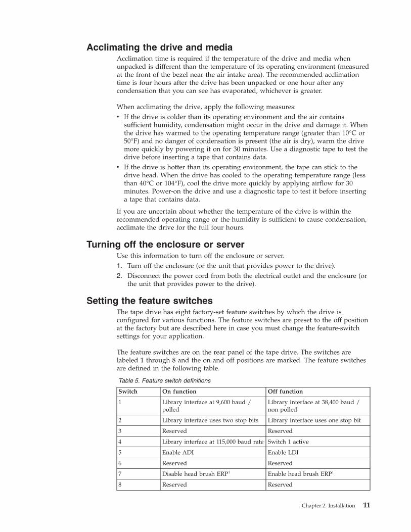
Setting the feature switchesThe tape drive has eight factory-set feature switches by which the drive isconfigured for various functions. The feature switches are preset to the off positionat the factory but are described here in case you must change the feature-switchsettings for your application.
The feature switches are on the rear panel of the tape drive. The switches arelabeled 1 through 8 and the on and off positions are marked. The feature switchesare defined in the following table.
Table 5. Feature switch definitions
Switch On function Off function
1 Library interface at 9,600 baud /polled
Library interface at 38,400 baud /non-polled
2 Library interface uses two stop bits Library interface uses one stop bit
3 Reserved Reserved
4 Library interface at 115,000 baud rate Switch 1 active
5 Enable ADI Enable LDI
6 Reserved Reserved
7 Disable head brush ERP1 Enable head brush ERP1
8 Reserved Reserved
Chapter 2. Installation 11

Table 5. Feature switch definitions (continued)
Switch On function Off function
Note: The default settings for the feature switches are all switches placed in the offposition.
*The head brush error recovery procedure (ERP) is intended to prevent a permanent reador write error by removing debris that might have accumulated on the read or write head.In order to brush the head, the tape must be unthreaded to expose the head. This forcesthe loader to be cycled to enable re-thread. During the loader cycling, the back of thecartridge will temporarily extend beyond the front of the bezel. Extension of the cartridgeis problematic in some automation environments, so you have the ability to disable thisfunction. If the head brush ERP is disabled, the drive will immediately report thepermanent error instead of activating the head brush ERP.
Mounting the drive in an enclosure or serverUse this information to mount the drive in an enclosure or server.
When mounting the drive:
v Use an appropriate screw length.v Make sure that no objects such as screw heads, cables, or adjacent devices, are
pressing against the frame.v Do not obstruct the ventilation slots at the rear of the drive.v Allow sufficient space for accessing the drive's front panel controls.
To mount the drive into an enclosure or server:
1. Remove the cover of your enclosure or server (refer to the instructions in thedocumentation provided with your enclosure or server).
2. Place the drive into your enclosure or server so that the tape load compartmentof the drive faces the tape load compartment of the enclosure or server.
3. Insert two M3 screws into the mounting holes of the two side brackets locatedon the left and right sides of the chassis.
Attention: When the mounting screws or drive rail prongs are inserted into thedrive, they must not extend farther than 2.5 mm (0.098 in.) inside the chassis.Otherwise, they might damage the drive.
Connecting and testing power to the driveThe drive does not contain its own power source; it must be powered externally.
To connect and test power to the drive, complete the following steps:1. Ensure that the enclosure (or unit that supplies power to the drive) is powered
off.2. Ensure that the power cord is disconnected from both the enclosure (or unit
that supplies power to the drive) and the power outlet.3. Connect the enclosure (or unit that supplies power to the drive) internal power
cable to the power connector on the drive.4. Connect the power cord to the enclosure (or unit that supplies power to the
drive) and to the electrical outlet.
12 IBM Half High LTO Ultrium Gen 6 Internal SAS Tape Drive: Installation and User's Guide

5. Review the location of the single-character display (SCD) and the status LED in“Front panel of the drive” on page 2. To make sure that the drive is receivingpower, watch for the following while turning on the power to the enclosure orserver:v During the power-on/initialization and POST (Power-On Self Test), the SCD
briefly displays , then becomes blank (not lit) when POST is complete andthere are no POST errors. If a POST error has been detected, an error codewill be displayed in the SCD and the status LED will flash amber.Attention: If the SCD does not come on, the drive might not be gettingpower.
v The status LED will be off during the initial power-on and initialization. Thestatus LED briefly becomes green and then becomes amber during theremainder of the power-on and initialization phase. The status LED becomessolid green after the power-on/initialization and POST are complete.
6. Turn off the enclosure or server.7. Disconnect the power cord from both the enclosure or server and the electrical
outlet.
Connecting the cableConnect the enclosure or server's internal SAS cable to the SAS connector on thedrive. Attach the host side (data and power) of the SAS cable included with yourtape drive to the SAS and power connectors on your server. Then, attach the driveside to the drive connector (for the drive connector location, see “Rear panel of thedrive” on page 2.
Running drive diagnosticsUse this information to run the drive diagnostics tool.1. Replace the cover on the enclosure or server.2. If you are not already connected to a power source, connect the power cord to
both the enclosure or server and the electrical outlet.3. Turn on the enclosure or server.4. Run one or more of the following drive diagnostics:
v “Function code 1: Run drive diagnostics” on page 28v “Function code 6: Run host interface wrap test” on page 32v “Function code 7: Run RS-422 wrap test” on page 33If an error code appears on the single-character display (SCD), go toAppendix C, “Error codes and messages,” on page 63. If no error appears,continue to the next step.
5. Turn off the enclosure or server.6. Disconnect the power cord from both the enclosure or server and the electrical
outlet.
Installing device driversUse this information to install device drivers.
A device driver is firmware that enables the tape drive to interact with a variety ofservers. Refer to “Supported device drivers” on page 6 for instructions ondownloading the latest device drivers.
Chapter 2. Installation 13
If you intend to use the tape drive with a commercial software application, refer tothat application's installation instructions to install the device driver and configurethe tape drive.
If you do not intend to use the tape drive with a commercial software application,refer to the IBM Tape Device Drivers Installation and User’s Guide.
Connecting the external interface cable (enclosure or serverinstallations only)
For information about connecting the enclosure or server, see the documentationfor your enclosure or server.
Connecting the external SAS interface to the serverUse this information to connect the external SAS interface to the server.
To connect the enclosure or server to the SAS interface, complete the followingsteps:1. Connect the external SAS cable that ships with the drive to both the enclosure
or server (for the location of the connectors, refer to the documentation foryour enclosure or server).
2. Run the applicable SAS attachment verification procedure for your server.
If you want to power a device on or off while it is connected to the same bus as adrive, you can do so if, during the power-on cycle, you quiesce all devices(including the drive) on the bus.
Configuring the drive to the server, switch, or hubTo configure the drive to work with the server, see the documentation for thatserver, switch, or hub.
The drive is now ready for use.
Updating firmwareUse this information to update firmware.
Attention: When updating firmware, do not turn off power to the drive until theupdate is complete, or the firmware update might not take effect.
It is your responsibility to make sure that the drive has the latest firmware.Periodically check for updated levels of drive firmware by visiting the IBMwebsite.
To download the latest firmware, go to http://www-947.ibm.com/support/entry/portal/, or complete the following steps.
Note: Changes are made periodically to the IBM website. The actual proceduremight vary slightly from what is described in this document.1. Go to http://www-947.ibm.com/support/entry/portal/.2. In the Search support and downloads text field at the bottom of the screen,
type tape files and press Enter.3. In the list of search results, click the link Tape Files (index) - Software for tape
drives and libraries.
14 IBM Half High LTO Ultrium Gen 6 Internal SAS Tape Drive: Installation and User's Guide

Registering for My SupportUse this information to register for My Support.
My Support registration provides e-mail notification when new firmware levelshave been updated and are available for download and installation. To register forMy Support, visit the web at http://www.ibm.com/support/mySupport.
Chapter 2. Installation 15

16 IBM Half High LTO Ultrium Gen 6 Internal SAS Tape Drive: Installation and User's Guide

Chapter 3. Operating the drive
Operating the drive involves using the following front panel items.v Power buttonv Single-character display (SCD)v SCD dotv Ready and Fault status lightsv Unload buttonv Encryption status light
Operating modesThe drive functions in the following modes.
Operation modeOperation mode functions include reading and writing data, cartridgemanipulation, error reporting, and firmware updating using an FMRcartridge. For more information, see “Status lights” on page 18.
Maintenance modeMaintenance mode functions include drive diagnostic, creating orunmaking FMR cartridge, and drive dump manipulation (force to RAM,copy to tape, copy to flash memory, and erase flash). For more information,see “Diagnostic and maintenance functions” on page 25.
The Unload button is used to switch between modes. For more information, see“Unload button” on page 21.
Power buttonThe Power button is a push button that turns the tape drive on or off.
The button is located on the front panel (see “Front panel of the drive” on page 2).When the Power button is in the off position, the primary electrical power withinthe enclosure or server is still active. To remove all electrical power to theenclosure or server, unplug the power cord from the receptacle at the rear of thedrive.
When the unit is powered-on but idle, the Ready light (see “Front panel of thedrive” on page 2) is solid green; when it is performing a function, the Ready lightis flashing green.
Single-character display (SCD)This section describes the SCD in the front panel of the drive.
The SCD (see “Front panel of the drive” on page 2) presents a single-charactercode for:v Error conditions and informational messagesv Diagnostic or maintenance functions (while in Maintenance mode only)
© Copyright IBM Corp. 2013 17

Appendix C, “Error codes and messages,” on page 63 lists the codes for errorconditions and informational messages. If multiple errors occur, the code with thehighest priority (represented by the lowest number) displays first. When the erroris corrected, the code with the next highest priority displays, and so on until noerrors remain.
“Diagnostic and maintenance functions” on page 25 lists the single-character codesthat represent diagnostic or maintenance functions. To initiate a function the unitmust be in Maintenance mode.
The SCD is blank during normal operation.
SCD dot
If a drive dump is present while the drive is in Maintenance mode, a single dot
illuminates in the lower right corner of the SCD (see 8 ). To copy the dump, see“Function code 5: Copy drive dump” on page 31.
The SCD dot is on solid if the dump is in RAM memory. The SCD dot flashes ifthe dump is in FLASH memory.
The SCD dot turns off when you obtain a dump with IBM TotalStorage TapeDiagnostic Tool (ITDT) or SCSI command, or update the drive firmware.
Note: If the drive dump is stored in RAM memory (SCD dot on solid), the dumpwill be lost when you turn OFF the power or reset the drive.
Status lightsUse this information for the status lights on the front panel of the drive.
The status lights (see “Front panel of the drive” on page 2) are LEDs that provideinformation about the state of the drive. The Ready status light is green and theFault status light is amber, and solid or flashing when lit. The Encryption statuslight is white.
Mode SCD Ready LED (green) Fault LED (amber)
Operational Blank On Off
Activity (tape movement)in Operational mode
Blank Flashing Off
Maintenance Solid character Flashing On
Executing maintenanceselection
Flashing character Off On
Error condition Solid character Off Flashing
Power is turned on or areset is initiated
Random segments Off On
Note: The white Encryption status light will be on when the tape drive has acartridge loaded and all data on this cartridge is encrypted (excluding the label).This applies to LTO Ultrium 6 and Ultrium 5 cartridges only.
Table 6 on page 19 lists the conditions of the status lights and Single-characterdisplay (SCD) and provides an explanation of what each condition means.
18 IBM Half High LTO Ultrium Gen 6 Internal SAS Tape Drive: Installation and User's Guide

Table 6. Meaning of status lights and single-character display (SCD)
Readystatus light
Fault statuslight
Encryptionstatus light
SCD SCD dot Meaning
Off Off Off Off Off The drive has no power or is poweredoff.
Green andsolid
Off On or off Off Off The drive is powered on and in an idlestate.Note: If a cartridge is loaded, the whiteEncryption status light will be on whenall the data on the cartridge is encrypted(excluding the label). This applies toLTO Ultrium 6 and Ultrium 5 cartridgesonly.
Flashinggreen (onceper second)
Off On or off Off Off The drive is reading from the tape,writing to the tape, rewinding the tape,locating data on the tape, loading thetape, or unloading the tape.Note: The white Encryption status lightwill be on when all the data on thecartridge is encrypted (excluding thelabel). This applies to LTO Ultrium 6and Ultrium 5 cartridges only.
Flashinggreen (onceper second)
Off Off Off Off If the drive contains a cartridge whenthe drive is turned on, the drivecompletes POST and slowly rewinds thetape (the process may take up to 10minutes). The light stops blinking andbecomes solid when the drive completesthe recovery and is ready for a read orwrite operation. To eject the cartridge,press the Unload button.
Off Amber andsolid
Off Displaying anerror code orMaintenance
modefunction
On or off The drive is displaying error codes fromthe error code log on the SCD. For moreinformation, see “Function code 9:Display error code log” on page 34 andAppendix C, “Error codes andmessages,” on page 63.
Chapter 3. Operations 19

Table 6. Meaning of status lights and single-character display (SCD) (continued)
Readystatus light
Fault statuslight
Encryptionstatus light
SCD SCD dot Meaning
On or off On or off On or Off Displayingrandom
segments,then blank,
thendisplaying
randomsegments,
thendisplaying
, thenblank
On or off During power on, or a drive reset, thedrive front panel will display driveprogress as follows:
1. SCD will display random segments(no LEDs on).
2. SCD will display random segments(LEDs - green on, amber off)
3. SCD will display random segments(LEDs - green off, amber on)
4. SCD will display [8] (LEDs - greenoff, amber on)
5. SCD will go blank (LEDs - green on,amber off) after the power is turnedon or after the drive is reset.
If an error is detected when the drivepower is turned on or during a reset,the tape drive posts an error code to theSCD. To determine the error, locate thecode in Appendix C, “Error codes andmessages,” on page 63.
Off Amber andsolid
Off On or off The drive is entering or exiting fromMaintenance mode. For moreinformation, see “Function code 0:Maintenance mode” on page 28.
Off Amber andsolid
Off Flashingselectedfunction
On or off The drive is executing the selectedfunction while in Maintenance mode.
Off Flashingamber (onceper second)
Off Displayingerror code
Off An error occurred and the drive ormedia may require service, or it mayrequire cleaning. Note the code on theSCD, then go to Appendix C, “Errorcodes and messages,” on page 63 todetermine the action that is required.
Off Flashingamber
OffDisplaying
Off The drive needs to be cleaned.
Off Flashingamber
Off DisplayingFunction
code orflashing
Off The drive is updating firmware. 1 The
SCD will display a if an FMRcartridge is in use. The SCD will be offif the SAS interface is in use. For moreinformation, see “Updating firmware”on page 14.
Off Flashingamber (twiceper second)
Off Off Off The drive detected an error and isperforming a firmware recovery. It willreset automatically.
Off Amber andsolid
OffFlashing
Off The drive is ready for a cartridge to beloaded.
Off Flashingamber (twiceper second)
Off Off On There is a drive dump in flash memory.
20 IBM Half High LTO Ultrium Gen 6 Internal SAS Tape Drive: Installation and User's Guide

Table 6. Meaning of status lights and single-character display (SCD) (continued)
Readystatus light
Fault statuslight
Encryptionstatus light
SCD SCD dot Meaning
1 Power should not be disconnected from the drive until the microcode update is complete. The drive indicates thatthe update is complete by resetting and performing POST.
Unload buttonThis section describes the functions of the Unload button.
The Unload button (see “Front panel of the drive” on page 2) performs thefollowing functions:
Table 7. Functions that the Unload button performs
Unload button Function How to initiate the function
Rewind the tape into thecartridge and eject thecartridge from the drive
Press the Unload button once. The status light flashes green while the drive isrewinding and unloading.Note: During a rewind and eject operation, the drive does not accept SCSI commandsfrom the server.
Place the drive inMaintenance mode
Ensure that the drive is unloaded. Then, within 2 seconds, press the Unload buttonthree times. The drive is in Maintenance mode when the status light becomes solid
amber and appears in the SCD.Note: While in Maintenance mode, the drive does not accept SCSI interfacecommands.Note: If you attempt to enter Maintenance mode with a cartridge in the drive, thedrive will rewind and eject the cartridge. Remove the cartridge and repeat the stepsfor entering Maintenance mode.
Scroll through themaintenance functions
While in Maintenance mode, press the Unload button once per second to increase thedisplay character by one. When you reach the character of the diagnostic ormaintenance function that you want (see “Diagnostic and maintenance functions” onpage 25), press and hold the Unload button for 3 seconds.
Exit Maintenance modePress the Unload button once per second to increment the display character untildisplays. Then press and hold the Unload button for three seconds. Maintenance modeis exited when the status light becomes solid green and the SCD becomes blank.
Force a drive dump (partof the Maintenance mode)
Attention: If the drive detects a permanent error and displays an error code, itautomatically forces a drive dump (also known as a save of the firmware trace). If youforce a drive dump, the existing dump will be overwritten and data will be lost. Afteryou force a drive dump, do not turn off the power to the drive or you might lose thedump data.
Choose one of the following procedures:
v If the drive is in Maintenance mode (status light is flashing and fault light is solid),see “Function code 4: Force a drive dump” on page 30.
v If the drive is in Operating mode (status light is solid or flashing green), press andhold the Unload button for ten seconds.
If captured dump data exists, the drive places it into a dump area. For informationabout retrieving the data, see “Procedure 1: Inspecting a cartridge for damage” onpage 53.
Chapter 3. Operations 21
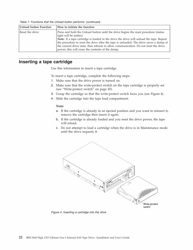
Table 7. Functions that the Unload button performs (continued)
Unload button Function How to initiate the function
Reset the drive Press and hold the Unload button until the drive begins the reset procedure (statuslight will be amber).Note: If a tape cartridge is loaded in the drive the drive will unload the tape. Repeatthe procedure to reset the drive after the tape is unloaded. The drive saves a dump ofthe current drive state, then reboots to allow communication. Do not reset the drivepower; this will erase the contents of the dump.
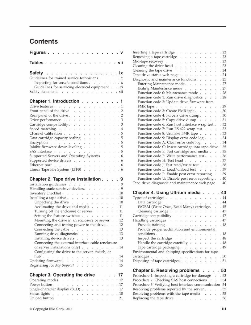
Inserting a tape cartridgeUse this information to insert a tape cartridge.
To insert a tape cartridge, complete the following steps:1. Make sure that the drive power is turned on.2. Make sure that the write-protect switch on the tape cartridge is properly set
(see “Write-protect switch” on page 45).3. Grasp the cartridge so that the write-protect switch faces you (see Figure 4).4. Slide the cartridge into the tape load compartment.
Note:
a. If the cartridge is already in an ejected position and you want to reinsert it,remove the cartridge then insert it again.
b. If the cartridge is already loaded and you reset the drive power, the tapewill reload.
c. Do not attempt to load a cartridge when the drive is in Maintenance modeuntil the drive requests it.
Figure 4. Inserting a cartridge into the drive
22 IBM Half High LTO Ultrium Gen 6 Internal SAS Tape Drive: Installation and User's Guide

Removing a tape cartridgeUse this information to remove a tape cartridge.
Attention: To clean the tape drive, use only an IBM LTO Ultrium CleaningCartridge. The use of cleaning methods other than an LTO cleaning cartridgemight cause damage to the drive.
To remove a tape cartridge, complete the following steps:1. Make sure that the drive power is turned on.2. Press the Unload button. The drive rewinds the tape and partially ejects the
cartridge. The Ready light flashes green while the tape rewinds, then becomesblank before the cartridge partially ejects.
3. After the cartridge partially ejects, grasp the cartridge and remove it.
Important: Always remove an ejected cartridge before reinserting it.
Whenever you unload a tape cartridge, the drive writes any pertinent informationto the cartridge memory.
Mid-tape recoveryIf the tape drive is reset while a cartridge is loaded, the drive will slowly rewindthe tape and eject the cartridge. If the drive power is turned off and then on againwhile a cartridge is loaded, the drive will slowly rewind the tape. The drive willnot automatically eject the cartridge.
The Ready light flashes and the SCD will be counting down from 9 to 0, indicatingthe approximate cartridge rewinding status. Between the counts, the SCD displaysrandom segments while the tape is rewinding into the cartridge. Push the Unloadbutton to eject the cartridge when the Ready light stops flashing.
Cleaning the drive headUse this information to clean the drive head.
Attention: When cleaning the drive head, use the IBM LTO Ultrium CleaningCartridge. You can use another LTO cleaning cartridge, but it might not meet thestandards of reliability established by IBM.
Clean the drive head whenever is displayed on the single-character display andthe status light is flashing amber once per second. You do not need to clean thedrive head on a periodic basis.
Note: In Maintenance mode, a flashing with the solid amber status light,means to insert a cartridge, not clean the drive head.
To clean the head, insert the cleaning cartridge into the tape load compartment (see“Front panel of the drive” on page 2). The drive performs the cleaningautomatically in less than 2 minutes and then ejects the cartridge. The drive willperform a short load and unload test while ejecting the drive. Wait for the drive tofinish before removing the cartridge.
Note: The drive will automatically eject an expired cleaning cartridge.
Chapter 3. Operations 23

The IBM LTO Ultrium Cleaning Cartridge is valid for 50 uses, and then must bereplaced.
Cleaning the tape driveClean the exterior surface of the tape drive with a damp towel. If you use a liquidall-purpose cleaner, apply it to the towel. Do not spray cleaner directly on the tapedrive.
Do not clean the interior of the tape drive; damage may result.
Tape drive status web pageThe status of the tape drive is accessible from the tape drive’s Ethernet port.
The drive status can be viewed from the web page. The drive status cannot bechanged from the web page. The tape drive status is available when the drive isoperating or idle.
Note: The drive must be powered on.1. Connect the host computer or a laptop to the tape drive’s Ethernet port (RJ45
connector) using an Ethernet patch cable.2. Use a web browser to connect to http://169.254.0.3 to view the current tape
drive status on an HTML web page.
Note:
a. If the drive’s IP address has been changed, use that address instead.b. The web page is static, so it must be refreshed frequently to show the latest
drive status.
The tape drive model and serial number are shown at the top of the page.
The web page is divided into sections by topic. The topics are:v Drive Informationv Host Informationv Ethernet Settingsv VPD Encryption Settingsv Drive Statistics
Figure 5. Drive status web page
24 IBM Half High LTO Ultrium Gen 6 Internal SAS Tape Drive: Installation and User's Guide
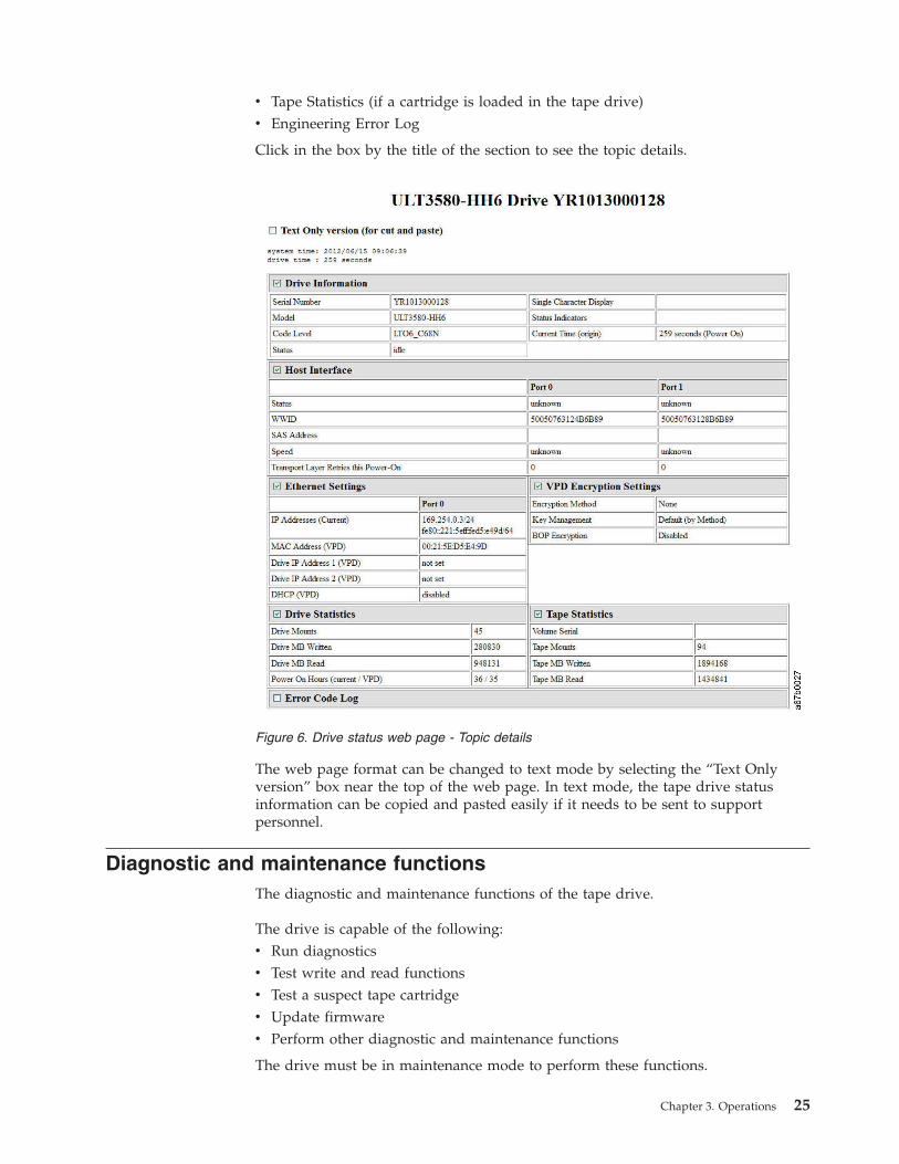
v Tape Statistics (if a cartridge is loaded in the tape drive)v Engineering Error Log
Click in the box by the title of the section to see the topic details.
The web page format can be changed to text mode by selecting the “Text Onlyversion” box near the top of the web page. In text mode, the tape drive statusinformation can be copied and pasted easily if it needs to be sent to supportpersonnel.
Diagnostic and maintenance functionsThe diagnostic and maintenance functions of the tape drive.
The drive is capable of the following:v Run diagnosticsv Test write and read functionsv Test a suspect tape cartridgev Update firmwarev Perform other diagnostic and maintenance functions
The drive must be in maintenance mode to perform these functions.
Figure 6. Drive status web page - Topic details
Chapter 3. Operations 25

Attention: Maintenance functions cannot be performed concurrently with read orwrite operations. While in maintenance mode, the tape drive does not accept SCSIcommands from the server. The tape drive accepts LDI or RS-422 commands.
Table 8 describes each diagnostic and maintenance function that the drive canperform, gives the function code which appears on the Single-character display(SCD), and directs you to the instructions for performing the function. Use acustomer-supplied scratch (blank) data cartridge for diagnostic testing. Thediagnostic and maintenance functions are not supported on the WORM andpartitioned data tape cartridges.
Note: During normal operation the fan runs only when cooling is required. Thefan will be turned on and off during the POST and Run Drive Diagnostics todemonstrate that the fan is operational.
Table 8. Diagnostic and maintenance functions
Function code Diagnostic or maintenance function Instructions location
Exit Maintenance Mode: Causes the drive to becomeavailable for reading and writing data.
“Function code 0: Maintenance mode”on page 28
Run Drive Diagnostics: Runs tests to determinewhether the drive can properly load and unloadcartridges, and read and write data.
“Function code 1: Run drivediagnostics” on page 28
Update Tape Drive Firmware from FMR Tape:Loads updated firmware from a field microcodereplacement (FMR) tape.
“Function code 2: Update drivefirmware from FMR tape” on page 29
Create FMR Tape: Copies its field microcodereplacement (FMR) data to a customer-suppliedscratch (blank) data cartridge.
“Function code 3: Create FMR tape”on page 30
Force a Drive Dump: Performs a dump of data (alsoknown as saving a microcode trace).
“Function code 4: Force a drivedump” on page 30
Copy Drive Dump: Copies data from a drive dump(captured by using Function code 4) to the beginningof a customer-supplied scratch (blank) datacartridge, copies a drive dump to flash memory, orerases a dump from flash memory.
“Function code 5: Copy drive dump”on page 31
Run Host Interface Wrap Test: Performs a check ofthe circuitry from and to the connector.
“Function code 6: Run host interfacewrap test” on page 32
Run RS-422 Wrap Test: This test causes the drive toperform a check of the circuitry and connector forthe RS-422 interface.
“Function code 7: Run RS-422 wraptest” on page 33
Unmake FMR Tape: Erases the FMR data on acustomer-supplied scratch (blank) data cartridge andrewrite the cartridge memory on the tape. This turnsthe cartridge into a valid customer-supplied scratchdata cartridge.
“Function code 8: Unmake FMR tape”on page 33
Display Error Code Log: Displays the last 10 errorcodes, one at a time. The codes are ordered; the mostrecent is presented first and the oldest is presentedlast.
“Function code 9: Display error codelog” on page 34
Clear Error Code Log: Erases the contents of theerror code log.
“Function code A: Clear error codelog” on page 34
26 IBM Half High LTO Ultrium Gen 6 Internal SAS Tape Drive: Installation and User's Guide

Table 8. Diagnostic and maintenance functions (continued)
Function code Diagnostic or maintenance function Instructions location
Insert Cartridge into Tape Drive: This functioncannot be selected by itself, but is a part of othermaintenance functions (such as Run Tape DriveDiagnostics and Create FMR Tape) that require atape cartridge to be loaded.
“Function code C: Insert cartridge intotape drive” on page 35
Test Cartridge & Media: Performs tests to make surethat a suspect cartridge and its magnetic tape areacceptable.
“Function code E: Test cartridge andmedia” on page 35
Write Performance Test: Performs tests to make surethat the drive can read from and write to tape.
“Function code F: Write performancetest” on page 36
Test Head: Performs tests to make sure that the tapedrive head and tape-carriage mechanics are workingcorrectly.
“Function code H: Test head” on page37
Fast Read/Write Test: Performs tests to make surethat the drive can read from and write to tape.
“Function code J: Fast read/write test”on page 38
Load/Unload Test: Tests the ability of the drive toload and unload a tape cartridge.
“Function code L: Load/unload test”on page 39
Enable Post Error Reporting: When selected,deferred-check conditions are reported to the host.
“Function code P: Enable post errorreporting” on page 39
Disable Post Error Reporting: When selected,deferred-check conditions are NOT reported to thehost.
“Function code U: Disable post errorreporting” on page 40
Entering Maintenance modeThe drive must be in Maintenance mode to run drive diagnostics or maintenancefunctions.
To put the unit in Maintenance mode, complete the following steps:1. Make sure that no cartridge is in the drive.
2. Press the Unload button three times within 2 seconds. appears in the SCD,and the Fault light turns amber.
Note: If a cartridge is in the tape drive, it will eject the first time that you pressthe Unload button and the drive will not be placed in Maintenance mode. Tocontinue placing the drive in Maintenance mode, perform the preceding step.While in Maintenance mode, the drive will not accept a cartridge unless the
drive requests it. The SCD will display a flashing to indicate a cartridgeneeds to be inserted.
Maintenance functions cannot be performed concurrently with read or writeoperations. While in Maintenance mode, the drive does not acknowledge SCSIcommands from the server.
Exiting Maintenance modeUse this information to exit Maintenance mode.
The drive must be in Function code in order to exit Maintenance mode.
Chapter 3. Operations 27

To exit Maintenance mode:
1. Press the Unload button once per second until is displayed. Press and holdthe Unload button for 3 or more seconds then release the button to take the
drive out of Maintenance mode. If no error is detected, temporarily appearsin the SCD, and it goes blank. The drive then exits Maintenance mode and theReady light turns on.
2. If an error is detected, the SCD shows an error code but still exits Maintenancemode. To determine the error, locate the code in Appendix C, “Error codes andmessages,” on page 63. To clear the error, turn the power off, then on again.
Note: The drive also exits Maintenance mode automatically after it completes amaintenance function or after 10 minutes if no action has occurred.
Function code 0: Maintenance mode
Function code makes the drive available for running drive diagnostics ormaintenance functions, or exiting from Maintenance mode.1. Put the drive in Maintenance mode. For instructions, see “Entering
Maintenance mode” on page 27.2. To exit Maintenance mode, see “Exiting Maintenance mode” on page 27.
The drive exits Maintenance mode automatically after it completes a maintenancefunction or after 10 minutes if no action has occurred.
Function code 1: Run drive diagnosticsApproximate Run Time = 5 minutes per loop
Total Number of Loops = 1
Function code runs tests that determine whether the drive can properly loadand unload cartridges and read and write data.
Once you begin this test, the diagnostic begins the loop sequence. Time the firstloop by pressing the Unload button once to stop the diagnostic after thecompletion of the first loop, then record the time it takes for the test to complete.Compare the recorded time with the "Approximate Run Time" above. If the testruns successfully but the execution time is significantly longer than the"Approximate Run Time", run “Function code F: Write performance test” on page36. If the Write Performance Test fails, replace the media and exit Maintenancemode.
Attention: For this test, insert only a scratch (blank) data cartridge or a cartridgethat can be overwritten. During the test, the drive overwrites the data on thecartridge.
Note: If you inserted an invalid tape cartridge (e.g., Ultrium 3 or WORM tape
cartridge), error code or appears in the SCD. If you inserted awrite-protected cartridge, or the media has read-only compatibility (e.g., Ultrium 4
tape cartridge), error code appears in the SCD. In either case, the tape driveunloads the cartridge and exits Maintenance mode after the cartridge is removed.
To execute Function code 1: Run drive diagnostics, complete the following steps:
28 IBM Half High LTO Ultrium Gen 6 Internal SAS Tape Drive: Installation and User's Guide
1. Put the drive in Maintenance mode. For instructions, see “EnteringMaintenance mode” on page 27.
2. Press the Unload button once per second until appears in the SCD. (If youcycle past the desired code, press the Unload button once per second until thecode reappears.)
3. Press and hold the Unload button for 3 or more seconds, then release it to
select function . Wait for the SCD to change to a flashing , requesting acartridge.
4. Insert a scratch (blank) data cartridge. The SCD changes to a flashing andthe test begins. During the test, the drive will unload and load the cartridge.Do not remove the cartridge during the test.v If no error is detected, the diagnostic will loop and begin again. To stop the
loop, press the Unload button for one second and release. When the
diagnostic ends, temporarily appears in the SCD, and the tape drive exitsMaintenance mode.
v If an error is detected, the Fault light flashes and the drive posts an errorcode to the SCD. To determine the error, locate the code in Appendix C,“Error codes and messages,” on page 63. To clear the error either turn thepower off and then on again, or reboot the drive by pressing and holding theUnload button for 10 seconds.
Function code 2: Update drive firmware from FMR tapeAttention: When updating drive firmware, do not turn the drive power off untilthe update is complete or the firmware might be lost.
Function code loads drive firmware from a field microcode replacement (FMR)tape. The FMR tape must have been created by a LTO Ultrium 6 tape drive withthe same host interface, for example, SAS.
To execute Function code 2: Update drive firmware from FMR tape, complete thefollowing steps:1. Put the drive in Maintenance mode. For instructions, see “Entering
Maintenance mode” on page 27.
2. Press the Unload button once per second until appears in the SCD. (If youcycle past the desired code, press the Unload button once per second until thecode reappears.)
3. Press and hold the Unload button for three or more seconds, then release it to
select the function. The SCD changes to a flashing , requesting a cartridge.
4. Insert the FMR tape cartridge. The SCD changes to a flashing . The amberFault light will be solid during tape movement and flashing while code isbeing loaded. The green Ready light will be off. The tape drive loads theupdated firmware from the FMR tape into its erasable programmable read-onlymemory (EPROM) area.v If the update completes successfully, the tape drive rewinds and unloads the
FMR tape, resets itself, and is ready to use the new firmware. The driveautomatically reboots.
v If the update fails, the tape drive posts an error code to the SCD. Todetermine the error, locate the code in Appendix C, “Error codes andmessages,” on page 63. Push the Unload button to eject the cartridge. The
Chapter 3. Operations 29

drive unloads the FMR tape and exits Maintenance mode after the cartridgeis removed. Contact IBM Technical Support for problem determination ormachine replacement.
Function code 3: Create FMR tape
Function code copies the drive field microcode replacement (FMR) data to ascratch data cartridge. The resulting FMR tape can only be used to update thefirmware on other LTO Ultrium 6 tape drives with the same host interface (SAS).
Attention: For this function, insert only a scratch (blank) data cartridge or acartridge that can be overwritten. During the test, the drive overwrites the data onthe cartridge.
Note: If you inserted an invalid tape cartridge (e.g., Ultrium 3 or WORM tape
cartridge), error code or appears in the SCD. If you inserted awrite-protected cartridge, or the media has read-only compatibility (e.g., Ultrium 4
tape cartridge), error code appears in the SCD. In either case, the tape driveunloads the cartridge and exits Maintenance mode after the cartridge is removed.
To execute Function code 3: Create FMR tape, complete the following steps:1. Put the drive in Maintenance mode. For instructions, see “Entering
Maintenance mode” on page 27.
2. Press the Unload button once per second until appears in the SCD. (If youcycle past the desired code, press the Unload button once per second until thecode reappears.)
3. Press and hold the Unload button for 3 or more seconds, then release it to
select the function. The SCD changes to a flashing , requesting a cartridge.4. Insert a scratch (blank) data cartridge that is not write protected (or the tape
drive exits maintenance mode). The SCD changes to a flashing . The tapedrive copies the FMR data to the scratch data cartridge.v If the tape drive creates the FMR tape successfully, it rewinds and unloads
the new tape, exits Maintenance mode, and the tape is ready to use.v If the tape drive fails to create the FMR tape, it displays an error code. To
determine the error, see Appendix C, “Error codes and messages,” on page63. The tape drive then unloads the FMR tape and exits Maintenance modeafter the cartridge is removed.
Function code 4: Force a drive dump
Function code performs a dump of data collected by the drive (this process isalso known as saving a microcode trace).
To execute Function code 4: Force a drive dump, complete the following steps:1. Put the drive in Maintenance mode. For instructions, see “Entering
Maintenance mode” on page 27.
2. Press the Unload button once per second until appears in the SCD. (If youcycle past the desired code, press the Unload button once per second until thecode reappears.)
30 IBM Half High LTO Ultrium Gen 6 Internal SAS Tape Drive: Installation and User's Guide

3. Press and hold the Unload button for 3 or more seconds, then release it to
select the function. The drive performs the dump. The SCD shows , thengoes blank, and the drive exits Maintenance mode. To access the contents of thedump, see “Function code 5: Copy drive dump.”
Note: You can also force a drive dump when the tape drive is in normaloperating mode. Simply press and hold the Unload button for ten seconds. Thiscauses the drive to reboot.
Function code 5: Copy drive dump
Function code copies data from a drive dump (captured in Function code 4) tothe beginning of a scratch (blank) data cartridge.
Attention: For this function, insert only a scratch (blank) data cartridge or acartridge that can be overwritten. During the test, the drive overwrites the data onthe cartridge.
Note: If you inserted an invalid tape cartridge (e.g., Ultrium 3 or WORM tape
cartridge), error code or appears in the SCD. If you inserted awrite-protected cartridge, or the media has read-only compatibility (e.g., Ultrium 4
tape cartridge), error code appears in the SCD. In either case, the tape driveunloads the cartridge and exits Maintenance mode after the cartridge is removed.
To execute Function code 5: Copy drive dump, complete the following steps:1. Put the drive in Maintenance mode. (For instructions, see “Entering
Maintenance mode” on page 27.) Index through the Maintenance mode options
until is displayed on the SCD.2. Press and hold the Unload button for 3 seconds to select Function code 5. After
selecting Function code 5, the SCD will display option - . Press the Unloadbutton within 5 seconds to make a different selection. If no other selection is
made, the drive will perform option - .3. Press the Unload button once per second to cycle through the following
functions:
v - : no function
v - : copy dump to tape; clears RAM dump
v - : copy dump to flash memory; clears RAM dump
v - : erase flash memory
If you cycle past the desired code, press the Unload button once per seconduntil the code reappears.
4. Press and hold the Unload button for 3 or more seconds, then release it toselect one of the above functions.
5. If you selected - the drive will exit Maintenance mode. If you selected
- or - the SCD will change to a flashing while the procedure isbeing performed. After the procedure is completed the drive will exit
Maintenance mode. If you selected - the SCD will change to a flashingindicating that a data cartridge is to be inserted.
Chapter 3. Operations 31

6. Insert a scratch (blank) data cartridge within 60 seconds, or the drive will exitMaintenance mode. Make sure that the scratch cartridge is not write protected(or the tape drive exits Maintenance mode). The SCD flashes the selectionnumber while performing the function.v If the copy operation completes successfully, the tape drive rewinds and
unloads the tape, and exits Maintenance mode after the cartridge is removed.v If the copy operation fails, an error code appears in the SCD. To determine
the error, locate the code in Appendix C, “Error codes and messages,” onpage 63. The tape drive unloads the tape cartridge and exits Maintenancemode after the cartridge is removed.
Function code 6: Run host interface wrap testApproximate Run Time = 10 seconds per loop
Number of Loops = This test runs until stopped by pressing the Unload button.
Function code performs a check of the host interface circuitry and hostconnector on the drive.
To execute Function code 6: Run host interface wrap test:1. Make sure that the host interface wrap plug is connected to the host interface
connector at the rear of the drive.2. Place the drive in Maintenance mode. For instructions, see “Entering
Maintenance mode” on page 27.
3. Press the Unload button once per second until appears in the SCD. Index
through the Maintenance mode options until is displayed on the SCD.4. Press and hold the Unload button for 3 seconds to select Function code 6. After
selecting Function code 6 the SCD will display option - . Press theUnload button within 5 seconds to make a different selection. If no other
selection is made, the drive will perform option - .5. Press the Unload button once per second to cycle through the following
functions:
v - : test the primary SAS port
v - : test the secondary SAS port
v - : test both primary and secondary SAS ports at the same time(requires a wrap plug in both ports)
v - : exit6. Press and hold the Unload button for 3 or more seconds, then release it to
select one of the above functions. The drive automatically starts the test. If youcycle past the desired code, press the Unload button once per second until thecode reappears.
7. The SCD will display a flashing during the test.v If no error is detected, the diagnostic will loop and begin again. To stop the
loop, press the Unload button for one second and release. When the
diagnostic ends, temporarily appears in the SCD, and the tape drive exitsMaintenance mode.
32 IBM Half High LTO Ultrium Gen 6 Internal SAS Tape Drive: Installation and User's Guide
v If an error is detected, the Fault light flashes and the drive posts an errorcode to the SCD. To determine the error, locate the code in Appendix C,“Error codes and messages,” on page 63. To clear the error either turn thepower off and then on again, or reboot the drive by pressing and holding theUnload button for 10 seconds.
Function code 7: Run RS-422 wrap testApproximate Run Time = 10 seconds per loop
Number of Loops = This test runs until stopped by pressing the Unload button.
Note: This function is described here only for informational purposes. It is notsupported on the tape drive.
This test causes the drive to perform a check of the circuitry and connector for theRS-422 interface. This connector supports the Library Drive Interface (LDI) and theAutomation Drive Interface (ADI).
Before selecting this function, attach an LDI or RS-422 wrap plug to the drive LDIor RS-422 connector (in place of the LDI or RS-422 cable).1. Make sure that no cartridge is in the drive, and the correct wrap plug is
attached to the RS-422 connector.2. Put the drive in Maintenance mode. For instructions, see “Entering
Maintenance mode” on page 27.
3. Press the Unload button once per second until appears in the SCD. If you
cycle past , continue to press the Unload button until it displays again.4. To select the function, press and hold the Unload button for 3 seconds. After
you select the function, flashes and the drive automatically starts the test.v If no error is detected, the diagnostic will loop and begin again. To stop the
loop, press the Unload button for one second and release. When the
diagnostic ends, temporarily appears in the SCD, and the tape drive exitsMaintenance mode.
v If an error is detected, the Fault light flashes and the drive posts an errorcode to the SCD. To determine the error, locate the code in Appendix C,“Error codes and messages,” on page 63. To clear the error either turn thepower off and then on again, or reboot the drive by pressing and holding theUnload button for 10 seconds.
Function code 8: Unmake FMR tape
Function code erases the field microcode replacement (FMR) data and rewritesthe cartridge memory on the tape. This converts the cartridge into a valid scratch(blank) data cartridge.
To execute Function code 8: Unmake FMR tape, complete the following steps:1. Put the drive in Maintenance mode. For instructions, see “Entering
Maintenance mode” on page 27.
2. Press the Unload button once per second until appears in the SCD. (If youcycle past the desired code, press the Unload button once per second until thecode reappears.)
Chapter 3. Operations 33

3. Press and hold the Unload button for 3 or more seconds, then release it to
select function . The SCD changes to a flashing , requesting a cartridge.4. Insert the FMR data cartridge (or the tape drive exits Maintenance mode). The
SCD changes to a flashing . The tape drive erases the firmware on the tapeand rewrites the header in the cartridge memory to change the cartridge to avalid scratch (blank) data cartridge. The drive then ejects the cartridge and exitsMaintenance mode.
Note: If you inserted an invalid tape cartridge (e.g., Ultrium 3 or WORM tape
cartridge), error code or appears in the SCD. If you inserted awrite-protected cartridge, or the media has read-only compatibility (e.g.,
Ultrium 4 tape cartridge), error code appears in the SCD. In either case, thetape drive unloads the cartridge and exits Maintenance mode after thecartridge is removed.v If the tape drive creates the scratch tape successfully, it rewinds and unloads
the new tape, exits Maintenance mode, and the tape is ready to use.v If the tape drive fails to create the scratch tape, it displays an error code. To
determine the error, see Appendix C, “Error codes and messages,” on page63. The tape drive then unloads the FMR tape, and exits Maintenance modeafter the cartridge is removed.
Function code 9: Display error code log
Function code displays the last 10 error codes, one at a time. The codes areordered; the most recent is presented first and the oldest is presented last. If there
are no errors in the log, function code displays in the SCD and exitsMaintenance mode.
To execute Function code 9: Display error code log, complete the following steps:1. Put the drive in Maintenance mode. For instructions, see “Entering
Maintenance mode” on page 27.
2. Press the Unload button once per second until appears in the SCD. (If youcycle past the desired code, press the Unload button once per second until thecode reappears.)
3. Press the Unload button, then release it to view the most recent error code.4. Press and release the Unload button again to view successive error codes. Let 2
to 3 seconds pass between each depression. The green Ready light and amberFault light will flash on and off once for each successive error code. The SCD
will display when all the error codes have been displayed.5. After viewing all error codes, exit this function by pressing the Unload button
again. The SCD will display and exit Maintenance mode.
Function code A: Clear error code log
Function code erases the contents of the error code log.
To execute Function code A: Clear error code log, complete the following steps:1. Put the drive in Maintenance mode. For instructions, see “Entering
Maintenance mode” on page 27.
34 IBM Half High LTO Ultrium Gen 6 Internal SAS Tape Drive: Installation and User's Guide

2. Press the Unload button once per second until appears in the SCD. (If youcycle past the desired code, press the Unload button once per second until thecode reappears.)
3. Press and hold the Unload button for 3 or more seconds, then release it to
select the function. flashes in the SCD, followed by . The tape driveerases all errors from the error code log and exits Maintenance mode.
Function code C: Insert cartridge into tape driveYou cannot select this function; it is part of other maintenance functions (such asRun tape drive diagnostics and Create FMR tape) that require a tape cartridge tobe inserted.
Function code E: Test cartridge and mediaApproximate Run Time = 15 minutes per loop
Total Number of Loops = 10
Function code performs tests that determine whether a suspect cartridge and itsmagnetic tape are acceptable.
Press the Unload button to stop the diagnostic and exit Maintenance mode.Pressing the Unload button once will abort the test at the end of the current testloop. Pressing the Unload button twice will abort the test immediately. Wait for thedrive to rewind the tape and unload the cartridge.
Attention: When you perform this test, data on the suspect tape will beoverwritten.
Note: If you inserted an invalid tape cartridge (e.g., Ultrium 3 or WORM tape
cartridge), error code or appears in the SCD. If you inserted awrite-protected cartridge, or the media has read-only compatibility (e.g., Ultrium 4
tape cartridge), error code appears in the SCD. In either case, the tape driveunloads the cartridge and exits Maintenance mode after the cartridge is removed.
To execute Function code E: Test cartridge & media, complete the following steps:1. Put the drive in Maintenance mode. For instructions, see “Entering
Maintenance mode” on page 27.
2. Press the Unload button once per second until appears in the SCD. (If youcycle past the desired code, press the Unload button once per second until thecode reappears.)
3. Press and hold the Unload button for 3 or more seconds, then release it to
select the function. The SCD changes to a flashing , requesting a cartridge.4. Make sure that the write-protect switch on the cartridge is off, then insert the
cartridge (or the tape drive exits Maintenance mode). The SCD changes to
flashing . The tape drive runs the tests.v If no error is detected, the diagnostic will loop and begin again. To stop the
loop, press the Unload button for one second and release. When the
diagnostic ends, temporarily appears in the SCD, and the tape drive exitsMaintenance mode.
Chapter 3. Operations 35

v If an error is detected, the Fault light flashes and the drive posts an errorcode to the SCD. To determine the error, locate the code in Appendix C,“Error codes and messages,” on page 63. To clear the error either turn thepower off and then on again, or reboot the drive by pressing and holding theUnload button for 10 seconds.
Function code F: Write performance testApproximate Run Time = 7 minutes per loop
Total Number of Loops = 10
Function code performs tests to make sure that the drive can read from andwrite to tape.
Press the Unload button to stop the diagnostic and exit Maintenance mode.Pressing the Unload button once will abort the test at the end of the current testloop. Pressing the Unload button twice will abort the test immediately. Wait for thedrive to rewind the tape and unload the cartridge.
Attention: For this test, insert only a scratch (blank) data cartridge or a cartridgethat can be overwritten. During the test, the drive overwrites the data on thecartridge.
Note: If you inserted an invalid tape cartridge (e.g., Ultrium 3 or WORM tape
cartridge), error code or appears in the SCD. If you inserted awrite-protected cartridge, or the media has read-only compatibility (e.g., Ultrium 4
tape cartridge), error code appears in the SCD. In either case, the tape driveunloads the cartridge and exits Maintenance mode after the cartridge is removed.
To execute Function code F: Write performance test, complete the following steps:1. Put the drive in Maintenance mode. For instructions, see “Entering
Maintenance mode” on page 27.
2. Press the Unload button once per second until appears in the SCD. (If youcycle past the desired code, press the Unload button once per second until thecode reappears.)
3. Press and hold the Unload button for 3 or more seconds, then release it to
select the function. The SCD changes to a flashing , requesting a cartridge.
4. Insert a scratch (blank) data cartridge. The SCD changes to a flashing andthe tape drive runs the tests.v If no error is detected, the diagnostic will loop and begin again. To stop the
loop, press the Unload button for one second and release. When the
diagnostic ends, temporarily appears in the SCD, and the tape drive exitsMaintenance mode.
v If an error is detected, the Fault light flashes and the drive posts an errorcode to the SCD. To determine the error, locate the code in Appendix C,“Error codes and messages,” on page 63. To clear the error either turn thepower off and then on again, or reboot the drive by pressing and holding theUnload button for 10 seconds.
36 IBM Half High LTO Ultrium Gen 6 Internal SAS Tape Drive: Installation and User's Guide

Function code H: Test headApproximate Run Time = 10 minutes per loop
Total Number of Loops = 10
Function code performs tests to make sure that the tape drive head andtape-carriage mechanics work correctly.
Once you begin this test, the diagnostic begins the loop sequence. Time the firstloop by pressing the Unload button once to stop the diagnostic after thecompletion of the first loop, then record the time it takes for the test to complete.Compare the recorded time with the "Approximate Run Time" above. If the testruns successfully but the execution time is significantly longer than the"Approximate Run Time", run “Function code F: Write performance test” on page36. If the Write Performance Test fails, replace the media and exit Maintenancemode.
Press the Unload button to stop the diagnostic and exit Maintenance mode.Pressing the Unload button once will abort the test at the end of the current testloop. Pressing the Unload button twice will abort the test immediately. Wait for thedrive to rewind the tape and unload the cartridge.
Attention: For this test, insert only a scratch (blank) data cartridge or a cartridgethat can be overwritten. During the test, the drive overwrites the data on thecartridge.
Note: If you inserted an invalid tape cartridge (e.g., Ultrium 3 or WORM tape
cartridge), error code or appears in the SCD. If you inserted awrite-protected cartridge, or the media has read-only compatibility (e.g., Ultrium 4
tape cartridge), error code appears in the SCD. In either case, the tape driveunloads the cartridge and exits Maintenance mode after the cartridge is removed.
To execute Function code H: Test head, complete the following steps:1. Put the drive in Maintenance mode. For instructions, see “Entering
Maintenance mode” on page 27.
2. Press the Unload button once per second until appears in the SCD. (If youcycle past the desired code, press the Unload button once per second until thecode reappears.)
3. Press and hold the Unload button for 3 or more seconds, then release it to
select the function. The SCD changes to a flashing , requesting a cartridge.
4. Insert a scratch (blank) data cartridge. The SCD changes to a flashing . Thetape drive runs the tests.v If no error is detected, the diagnostic will loop and begin again. To stop the
loop, press the Unload button for one second and release. When the
diagnostic ends, temporarily appears in the SCD, and the tape drive exitsMaintenance mode.
v If an error is detected, the Fault light flashes and the drive posts an errorcode to the SCD. To determine the error, locate the code in Appendix C,
Chapter 3. Operations 37

“Error codes and messages,” on page 63. To clear the error either turn thepower off and then on again, or reboot the drive by pressing and holding theUnload button for 10 seconds.
Function code J: Fast read/write testApproximate Run Time = 5 minutes per loop
Total Number of Loops = 10
Function code performs tests to make sure that the drive can read from andwrite to tape.
Once you begin this test, the diagnostic begins the loop sequence. Time the firstloop by pressing the Unload button once to stop the diagnostic after thecompletion of the first loop, then record the time it takes for the test to complete.Compare the recorded time with the "Approximate Run Time" above. If the testruns successfully but the execution time is significantly longer than the"Approximate Run Time", run “Function code F: Write performance test” on page36. If the Write Performance Test fails, replace the media and exit Maintenancemode.
Press the Unload button to stop the diagnostic and exit Maintenance mode.Pressing the Unload button once will abort the test at the end of the current testloop. Pressing the Unload button twice will abort the test immediately. Wait for thedrive to rewind the tape and unload the cartridge.
Attention: For this test, insert only a scratch (blank) data cartridge or a cartridgethat can be overwritten. During the test, the drive overwrites the data on thecartridge.
Note: If you inserted an invalid tape cartridge (e.g., Ultrium 3 or WORM tape
cartridge), error code or appears in the SCD. If you inserted awrite-protected cartridge, or the media has read-only compatibility (e.g., Ultrium 4
tape cartridge), error code appears in the SCD. In either case, the tape driveunloads the cartridge and exits Maintenance mode after the cartridge is removed.
To execute Function code J: Fast read/write test, complete the following steps:1. Put the drive in Maintenance mode. For instructions, see “Entering
Maintenance mode” on page 27.
2. Press the Unload button once per second until appears in the SCD. (If youcycle past the desired code, press the Unload button once per second until thecode reappears.)
3. Press and hold the Unload button for 3 or more seconds, then release it to
select the function. The SCD changes to a flashing , requesting a cartridge.
4. Insert a scratch (blank) data cartridge. The SCD changes to a flashing andthe tape drive runs the tests.v If no error is detected, the diagnostic will loop and begin again. To stop the
loop, press the Unload button for one second and release. When the
diagnostic ends, temporarily appears in the SCD, and the tape drive exitsMaintenance mode.
38 IBM Half High LTO Ultrium Gen 6 Internal SAS Tape Drive: Installation and User's Guide

v If an error is detected, the Fault light flashes and the drive posts an errorcode to the SCD. To determine the error, locate the code in Appendix C,“Error codes and messages,” on page 63. To clear the error either turn thepower off and then on again, or reboot the drive by pressing and holding theUnload button for 10 seconds.
Function code L: Load/unload testApproximate Run Time = 30 seconds per loop
Total Number of Loops = 10
Function code tests the ability of the drive to load and unload a tape cartridge.
Press the Unload button to stop the diagnostic and exit Maintenance mode.Pressing the Unload button once will abort the test at the end of the current testloop. Pressing the Unload button twice will abort the test immediately. Wait for thedrive to rewind the tape and unload the cartridge.
Attention: Even though no data is written during this test, use a blank (scratch)cartridge for this test.
To execute Function code L: Load/unload test, complete the following steps:1. Put the drive in Maintenance mode. For instructions, see “Entering
Maintenance mode” on page 27.
2. Press the Unload button once per second until appears in the SCD. (If youcycle past the desired code, press the Unload button once per second until thecode reappears.)
3. Press and hold the Unload button for 3 or more seconds, then release it to
select the function. The SCD changes to a flashing , requesting a cartridge.
4. Insert a scratch (blank) data cartridge. The SCD changes to a flashing andthe tape drive runs the tests.v If no error is detected, the diagnostic will loop and begin again. To stop the
loop, press the Unload button for one second and release. When the
diagnostic ends, temporarily appears in the SCD, and the tape drive exitsMaintenance mode.
v If an error is detected, the Fault light flashes and the drive posts an errorcode to the SCD. To determine the error, locate the code in Appendix C,“Error codes and messages,” on page 63. To clear the error either turn thepower off and then on again, or reboot the drive by pressing and holding theUnload button for 10 seconds.
Function code P: Enable post error reportingWhen post error reporting is enabled, deferred-check conditions are reported to the
host and temporary errors are reported in the sense data. Function code will bedisplayed in Maintenance mode when the drive has post error reporting enabled.
This selection is normally used as a request from support personnel.
To execute Function code P: Enable post error reporting, complete the followingsteps:
Chapter 3. Operations 39
1. Put the drive in Maintenance mode. For instructions, see “EnteringMaintenance mode” on page 27.
2. Press the Unload button once per second until either or appears in the
SCD. or will appear in the SCD to indicate the current setting for posterror reporting. If you cycle past the desired code, press the Unload buttononce per second until the code reappears.
3. Exit Maintenance mode if you do not want to change the current setting forpost error reporting. For instructions, see “Exiting Maintenance mode” on page27.
4. To disable post error reporting, press and hold the Unload button for 3 seconds
while appears in the SCD. The SCD changes to after you release theUnload button.
5. Press the Unload button once per second to select another Maintenance modefunction. To exit Maintenance mode, see “Exiting Maintenance mode” on page27.
Function code U: Disable post error reportingWhen post error reporting is disabled, deferred-check conditions are not reportedto the host and temporary errors are not reported in the sense data. This is thenormal (default) setting for the drive. When the drive has post error reporting
disabled, Function code will be displayed in Maintenance mode. The drive willdefault to post error reporting disabled after a reboot or power off/on cycle.
To execute Function code U: Disable post error reporting, complete the followingsteps:1. Put the drive in Maintenance mode. For instructions, see “Entering
Maintenance mode” on page 27.
2. Press the Unload button once per second until either or appears in the
SCD. or will appear in the SCD to indicate the current setting for posterror reporting. If you cycle past the desired code, press the Unload buttononce per second until the code reappears.
3. Exit Maintenance mode if you do not want to change the current setting forpost error reporting. For instructions, see “Exiting Maintenance mode” on page27.
4. To disable post error reporting, press and hold the Unload button for 3 seconds
while appears in the SCD. The SCD changes to after you release theUnload button.
5. Press the Unload button once per second to select another Maintenance modefunction. To exit Maintenance mode, see “Exiting Maintenance mode” on page27.
Tape drive diagnostic and maintenance web pageSeveral of the tape drive’s maintenance functions are run using the tape drive’sEthernet port. These are the same maintenance functions that are performed usingthe Unload button on the drive’s front panel.
Refer to the “Diagnostic and maintenance functions” on page 25 section in thisUser’s Guide for information about these maintenance functions.
40 IBM Half High LTO Ultrium Gen 6 Internal SAS Tape Drive: Installation and User's Guide

1. Connect the host computer or a laptop to the tape drive’s Ethernet port (RJ45connector) using an Ethernet patch cable.
2. Using a web browser, connect to http://169.254.0.3/service.html to access thetape drive maintenance function menu on an HTML web page.
Note: If the drive’s IP address has been changed, use that address instead.
The tape drive model and serial number are shown at the top of the page. A list ofthe maintenance functions is shown on the page.
Click the radio button next to the maintenance function, then click Run to start themaintenance function.
If the tape drive is installed in a library, some of the maintenance functions cannotbe run using the Ethernet procedure.
The status of the maintenance function is shown under the Drive Response. Theweb page is static so it must be refreshed frequently to show the latestmaintenance function status.
Press the Cancel now or Cancel at end of loop button to stop the maintenancefunction. It may take several minutes for the maintenance function to end.
Figure 7. Tape drive diagnostic page
Chapter 3. Operations 41

42 IBM Half High LTO Ultrium Gen 6 Internal SAS Tape Drive: Installation and User's Guide

Chapter 4. Using Ultrium media
Use this information for the usage of Ultrium media.
To make sure that your IBM Ultrium Tape Drive conforms to IBM's specificationsfor reliability, use only IBM LTO Ultrium tape cartridges. You may use otherLTO-certified data cartridges, but they may not meet the standards of reliabilitythat are established by IBM. The IBM LTO Ultrium Data Cartridge cannot beinterchanged with the media used in other IBM non-LTO Ultrium tape products.
Figure 8 shows the IBM LTO Ultrium Data Cartridge and its components.
LTO Cartridge Memory This is a chip that contains information about the cartridge and the tape, as wellas statistical information about the use of the cartridge. For more information, see“Cartridge Memory chip (LTO-CM)” on page 44.
Cartridge door The cartridge door protects the tape from contamination when the cartridge is outof the drive.
Leader pin The tape is attached to a leader pin, behind the cartridge door. When thecartridge is inserted into the drive, a threading mechanism pulls the pin (andtape) out of the cartridge, across the drive head, and onto a take-up reel. Thehead can then read or write data from or to the tape.
Write-protect switch This switch prevents data from being written to the tape cartridge. For moreinformation, see “Write-protect switch” on page 45.
Label area This provides a location to place a label.
Insertion guide This is a large, notched area that prevents the cartridge from being insertedincorrectly.
Figure 8. The IBM LTO Ultrium Data Cartridge
© Copyright IBM Corp. 2013 43
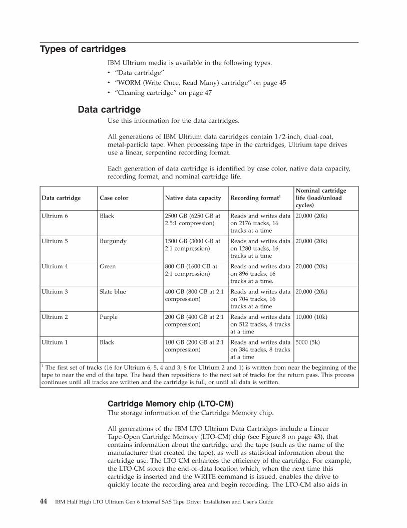
Types of cartridgesIBM Ultrium media is available in the following types.v “Data cartridge”v “WORM (Write Once, Read Many) cartridge” on page 45v “Cleaning cartridge” on page 47
Data cartridgeUse this information for the data cartridges.
All generations of IBM Ultrium data cartridges contain 1/2-inch, dual-coat,metal-particle tape. When processing tape in the cartridges, Ultrium tape drivesuse a linear, serpentine recording format.
Each generation of data cartridge is identified by case color, native data capacity,recording format, and nominal cartridge life.
Data cartridge Case color Native data capacity Recording format1Nominal cartridgelife (load/unloadcycles)
Ultrium 6 Black 2500 GB (6250 GB at2.5:1 compression)
Reads and writes dataon 2176 tracks, 16tracks at a time
20,000 (20k)
Ultrium 5 Burgundy 1500 GB (3000 GB at2:1 compression)
Reads and writes dataon 1280 tracks, 16tracks at a time
20,000 (20k)
Ultrium 4 Green 800 GB (1600 GB at2:1 compression)
Reads and writes dataon 896 tracks, 16tracks at a time.
20,000 (20k)
Ultrium 3 Slate blue 400 GB (800 GB at 2:1compression)
Reads and writes dataon 704 tracks, 16tracks at a time
20,000 (20k)
Ultrium 2 Purple 200 GB (400 GB at 2:1compression)
Reads and writes dataon 512 tracks, 8 tracksat a time
10,000 (10k)
Ultrium 1 Black 100 GB (200 GB at 2:1compression)
Reads and writes dataon 384 tracks, 8 tracksat a time
5000 (5k)
1 The first set of tracks (16 for Ultrium 6, 5, 4 and 3; 8 for Ultrium 2 and 1) is written from near the beginning of thetape to near the end of the tape. The head then repositions to the next set of tracks for the return pass. This processcontinues until all tracks are written and the cartridge is full, or until all data is written.
Cartridge Memory chip (LTO-CM)The storage information of the Cartridge Memory chip.
All generations of the IBM LTO Ultrium Data Cartridges include a LinearTape-Open Cartridge Memory (LTO-CM) chip (see Figure 8 on page 43), thatcontains information about the cartridge and the tape (such as the name of themanufacturer that created the tape), as well as statistical information about thecartridge use. The LTO-CM enhances the efficiency of the cartridge. For example,the LTO-CM stores the end-of-data location which, when the next time thiscartridge is inserted and the WRITE command is issued, enables the drive toquickly locate the recording area and begin recording. The LTO-CM also aids in
44 IBM Half High LTO Ultrium Gen 6 Internal SAS Tape Drive: Installation and User's Guide
determining the reliability of the cartridge by storing data about its age, how manytimes it has been loaded, and how many errors it has accumulated. Whenever atape cartridge is unloaded, the tape drive writes any pertinent information to thecartridge memory.
The LTO-CM storage capacity of the LTO Ultrium 6 is 16320 bytes, LTO Ultrium 4and 5 is 8160 bytes, and Ultrium 1, 2, and 3 is 4096 bytes.
Write-protect switchThe position of the write-protect switch on the tape cartridge determines whetheryou can write to the tape.
See Chapter 4, “Using Ultrium media,” on page 43 for the location of the switch.
If possible, use your server's application software to write-protect your cartridges(rather than manually setting the write-protect switch). This allows the server'ssoftware to identify a cartridge that no longer contains current data and is eligibleto become a scratch (blank) data cartridge. Do not write-protect scratch (blank)cartridges; the tape drive will not be able to write new data to them.
If the switch is in the locked position, (solid red), data cannot be written to thetape. If the switch is in the unlocked position (black void), data can be written tothe tape.
If you must manually set the write-protect switch, slide it left or right to thedesired position.
Capacity scalingTo control the capacity of the cartridge (for example, to obtain a faster seek time)issue the SCSI command SET CAPACITY.
For information about this command, refer to the IBM TotalStorage LTO UltriumTape DriveSCSI Reference in the IBM Support portal.
WORM (Write Once, Read Many) cartridgeCertain records-retention and data-security applications require a Write Once, ReadMany (WORM) method for storing data on tape. The LTO Ultrium generation 4, 5,and 6 drives enable WORM support when a WORM tape cartridge is loaded intothe drive.
Because standard read/write media are incompatible with the WORM feature, aspecially formatted WORM tape cartridge is required. Each WORM cartridge has aunique, worldwide cartridge identifier (WWCID), which is comprised of theunique CM chip serial number and the unique tape media serial number. Ultrium6 WORM cartridges are two-tone black and silvery-gray.
Chapter 4. Using Ultrium Media 45
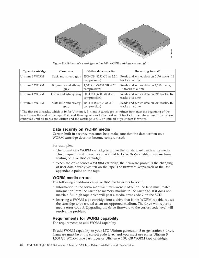
Type of cartridge Case color Native data capacity Recording format1
Ultrium 6 WORM Black and silvery gray 2500 GB (6250 GB at 2.5:1compression)
Reads and writes data on 2176 tracks, 16tracks at a time
Ultrium 5 WORM Burgundy and silverygray
1,500 GB (3,000 GB at 2:1compression)
Reads and writes data on 1,280 tracks,16 tracks at a time
Ultrium 4 WORM Green and silvery gray 800 GB (1,600 GB at 2:1compression)
Reads and writes data on 896 tracks, 16tracks at a time
Ultrium 3 WORM Slate blue and silverygray
400 GB (800 GB at 2:1compression)
Reads and writes data on 704 tracks, 16tracks at a time
1 The first set of tracks, which is 16 for Ultrium 6, 5, 4 and 3 cartridges, is written from near the beginning of thetape to near the end of the tape. The head then repositions to the next set of tracks for the return pass. This processcontinues until all tracks are written and the cartridge is full, or until all of your data is written.
Data security on WORM mediaCertain built-in security measures help make sure that the data written on aWORM cartridge does not become compromised.
For examples:v The format of a WORM cartridge is unlike that of standard read/write media.
This unique format prevents a drive that lacks WORM-capable firmware fromwriting on a WORM cartridge.
v When the drive senses a WORM cartridge, the firmware prohibits the changingof user data already written on the tape. The firmware keeps track of the lastappendable point on the tape.
WORM media errorsThe following conditions cause WORM media errors to occur.v Information in the servo manufacturer's word (SMW) on the tape must match
information from the cartridge memory module in the cartridge. If it does notmatch, a full-high tape drive will post a media error code 7 on the SCD.
v Inserting a WORM tape cartridge into a drive that is not WORM-capable causesthe cartridge to be treated as an unsupported medium. The drive will report amedia error code J. Upgrading the drive firmware to the correct code level willresolve the problem.
Requirements for WORM capabilityThe requirements to add WORM capability.
To add WORM capability to your LTO Ultrium generation 5 or generation 6 drive,firmware must be at the correct code level, and you must use either Ultrium 51,500 GB WORM tape cartridges or Ultrium 6 2500 GB WORM tape cartridges.
Figure 9. Ultrium data cartridge on the left; WORM cartridge on the right
46 IBM Half High LTO Ultrium Gen 6 Internal SAS Tape Drive: Installation and User's Guide
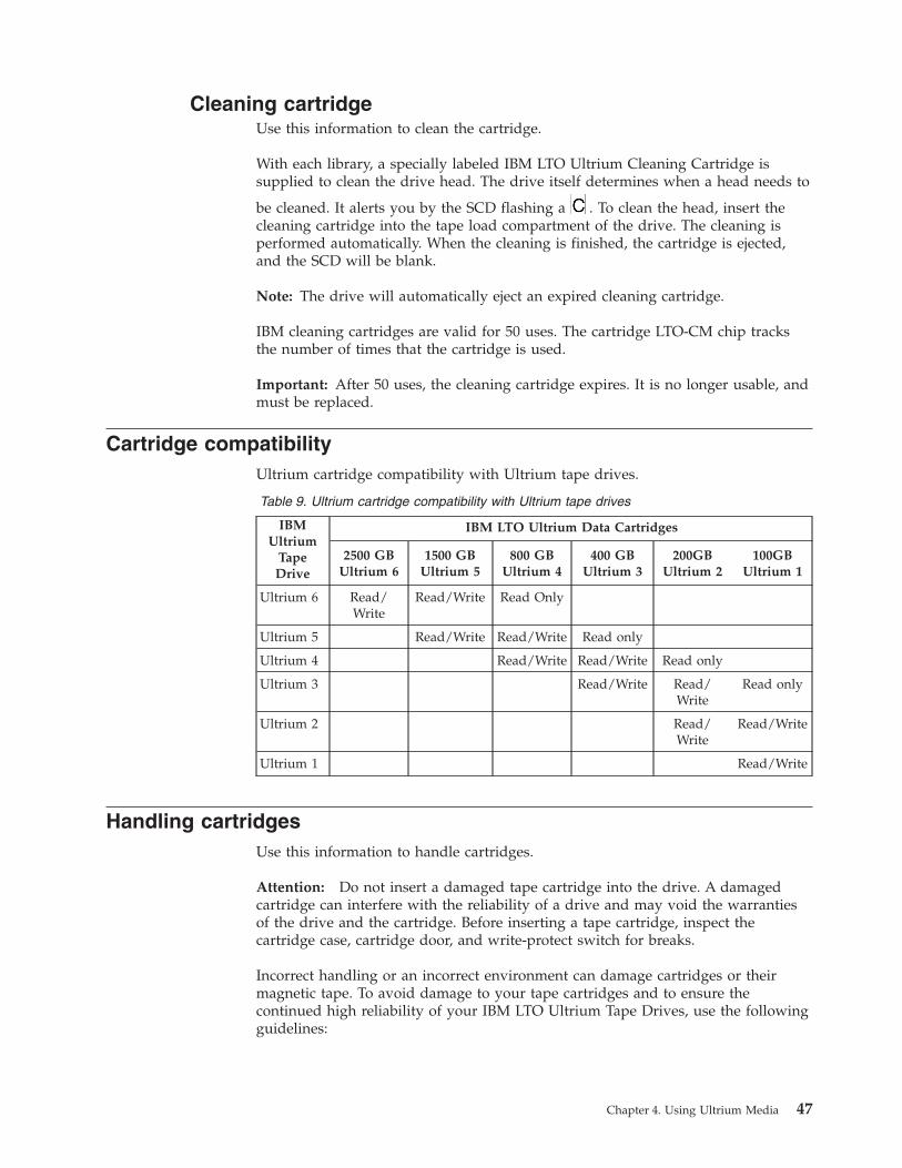
Cleaning cartridgeUse this information to clean the cartridge.
With each library, a specially labeled IBM LTO Ultrium Cleaning Cartridge issupplied to clean the drive head. The drive itself determines when a head needs to
be cleaned. It alerts you by the SCD flashing a . To clean the head, insert thecleaning cartridge into the tape load compartment of the drive. The cleaning isperformed automatically. When the cleaning is finished, the cartridge is ejected,and the SCD will be blank.
Note: The drive will automatically eject an expired cleaning cartridge.
IBM cleaning cartridges are valid for 50 uses. The cartridge LTO-CM chip tracksthe number of times that the cartridge is used.
Important: After 50 uses, the cleaning cartridge expires. It is no longer usable, andmust be replaced.
Cartridge compatibilityUltrium cartridge compatibility with Ultrium tape drives.
Table 9. Ultrium cartridge compatibility with Ultrium tape drives
IBMUltrium
TapeDrive
IBM LTO Ultrium Data Cartridges
2500 GBUltrium 6
1500 GBUltrium 5
800 GBUltrium 4
400 GBUltrium 3
200GBUltrium 2
100GBUltrium 1
Ultrium 6 Read/Write
Read/Write Read Only
Ultrium 5 Read/Write Read/Write Read only
Ultrium 4 Read/Write Read/Write Read only
Ultrium 3 Read/Write Read/Write
Read only
Ultrium 2 Read/Write
Read/Write
Ultrium 1 Read/Write
Handling cartridgesUse this information to handle cartridges.
Attention: Do not insert a damaged tape cartridge into the drive. A damagedcartridge can interfere with the reliability of a drive and may void the warrantiesof the drive and the cartridge. Before inserting a tape cartridge, inspect thecartridge case, cartridge door, and write-protect switch for breaks.
Incorrect handling or an incorrect environment can damage cartridges or theirmagnetic tape. To avoid damage to your tape cartridges and to ensure thecontinued high reliability of your IBM LTO Ultrium Tape Drives, use the followingguidelines:
Chapter 4. Using Ultrium Media 47

Provide trainingProper media handling and good practices.v Post procedures that describe proper media handling in places where people
gather.v Ensure that anyone who handles tape has been properly trained in handling and
shipping procedures. This includes operators, users, programmers, archivalservices, and shipping personnel.
v Ensure that any service or contract personnel who perform archiving areproperly trained in media-handling procedures.
v Include media-handling procedures as part of any services contract.v Define and make personnel aware of data recovery procedures.
Provide proper acclimation and environmental conditionsProper acclimation and environmental conditions to prepare for the cartridge.v Before using a cartridge, let it acclimate to the normal operating environment for
1 hour. If condensation is visible on the cartridge, wait an additional hour.v Make sure that all surfaces of a cartridge are dry before inserting it.v Do not expose the cartridge to moisture or direct sunlight.v Do not expose recorded or blank cartridges to stray magnetic fields of greater
than 50 oersteds (for example, terminals, motors, video equipment, X-rayequipment, or fields that exist near high-current cables or power supplies). Suchexposure can cause the loss of recorded data or make the blank cartridgeunusable.
v Maintain the conditions that are described in “Environmental and shippingspecifications for tape cartridges” on page 50.
Inspect the cartridgeBefore using the cartridge, perform the following steps.v Inspect the cartridge packaging to determine potential rough handling.v When inspecting a cartridge, open only the cartridge door. Do not open any
other part of the cartridge case. The upper and lower parts of the case are heldtogether with screws; separating them destroys the usefulness of the cartridge.
v Inspect the cartridge for damage before using or storing it.v Inspect the rear of the cartridge (the part that loads first into the tape load
compartment) and make sure that there are no gaps in the seam of the cartridgecase. If there are gaps in the seam, the leader pin might be dislodged. Go to“Repositioning a leader pin” on page 69.
v Check that the leader pin is properly seated (see “Repositioning a leader pin” onpage 69).
v If you suspect that the cartridge has been mishandled but it appears usable,copy any data onto a good cartridge immediately for possible data recovery.Discard the mishandled cartridge.
v Review handling and shipping procedures.
Handle the cartridge carefullyUse this information to handle the cartridge carefully.v Do not drop the cartridge. If the cartridge is dropped, slide the cartridge door
back and make sure that the leader pin is properly seated in the pin-retaining
48 IBM Half High LTO Ultrium Gen 6 Internal SAS Tape Drive: Installation and User's Guide

spring clips (see“Repositioning a leader pin” on page 69). If the leader pin hasbecome dislodged, see Appendix D, “Repairing a cartridge,” on page 69.
v Do not handle tape that is outside the cartridge. Handling the tape can damagethe tape surface or edges, which might interfere with read or write reliability.Pulling on tape that is outside the cartridge can damage the tape and the brakemechanism in the cartridge.
v Do not stack more than six cartridges.v Do not degauss a cartridge that you intend to reuse. Degaussing makes the tape
unusable.
Tape cartridge packagingTape cartridge packaging details.v When shipping a cartridge, use the original or better packaging.v Always ship or store a cartridge in a jewel case.v Use only a recommended shipping container that holds the cartridge securely in
its jewel case during transportation. Ultrium Turtlecases (by Perm-A-Store) havebeen tested and found to be satisfactory. They are available athttp://www.turtlecase.com.
v Never ship a cartridge in a commercial shipping envelope. Always place it in abox or package.
v If you ship the cartridge in a cardboard box or a box of a sturdy material, makesure that the following conditions are met:– Place the cartridge in polyethylene plastic wrap or bags to protect it from
dust, moisture, and other contaminants.
Figure 10. Tape cartridges in a Turtlecase
Chapter 4. Using Ultrium Media 49

– Pack the cartridge tightly; do not allow it to move around.– Double-box the cartridge (place it inside a box, then place that box inside the
shipping box) and add padding between the two boxes.
Environmental and shipping specifications for tape cartridgesBefore you use a tape cartridge, acclimate it to the operating environment toprevent condensation in the drive (the time will vary, depending on theenvironmental extremes to which the cartridge was exposed).
The best storage container for the cartridges (until they are opened) is the originalshipping container. The plastic wrapping prevents dirt from accumulating on thecartridges and partially protects them from humidity changes.
When you ship a cartridge, place it in its jewel case or in a sealed, moisture-proofbag to protect it from moisture, contaminants, and physical damage. Ship thecartridge in a shipping container that has enough packing material to cushion thecartridge and prevent it from moving within the container.
Table 10 gives the environment for operating, storing, and shipping LTO UltriumTape Cartridges.
Table 10. Environment for operating, storing, and shipping LTO media
Environmental specifications
Environmental factor Operating Operational storage1 Archival storage2 Shipping
Figure 11. Double-boxing tape cartridges for shipping
50 IBM Half High LTO Ultrium Gen 6 Internal SAS Tape Drive: Installation and User's Guide

Table 10. Environment for operating, storing, and shipping LTO media (continued)
Temperature10 to 45°C (50 to
113°F)16 to 32°C (61 to
90°F)16 to 25°C (61 to
77°F)-23 to 49°C (-9 to
120°F)
Relative humidity(non-condensing)
10 to 80% 20 to 80% 20 to 50% 5 to 80%
Maximum wet bulbtemperature
26°C (79°F) 26°C (79°F) 26°C (79°F) 26°C (79°F)
1 The short term or operational storage environment is for storage durations of up to six months.
2 The long term or archival storage environment is for durations of six months up to ten years.
Disposing of tape cartridgesUnder the current rules of the U.S. Environmental Protection Agency (EPA),regulation 40CFR261, the LTO Ultrium tape cartridge is classified as non-hazardouswaste. As such, it can be disposed of in the same way as normal office trash. Theseregulations are amended from time to time, and you should review them at thetime of disposal.
If your local, state, country (non-U.S.A.), or regional regulations are morerestrictive than EPA 40CFR261, you must review them before you dispose of acartridge. Contact your account representative for information about the materialsthat are in the cartridge.
If a tape cartridge must be disposed of in a secure manner, you can erase the dataon the cartridge by using a high-energy ac degausser (use a minimum of 4000oersted peak field over the entire space that the cartridge occupies). The tapeshould make two passes through the field at 90 degree orientation change for eachpass to achieve complete erasure. Some commercial degaussers have two magneticfield regions offset 90 degrees from each other to accomplish complete erasure inone pass for higher throughput. Degaussing makes the cartridge unusable.
If you burn the cartridge and tape, make sure that the incineration complies withall applicable regulations.
Chapter 4. Using Ultrium Media 51

52 IBM Half High LTO Ultrium Gen 6 Internal SAS Tape Drive: Installation and User's Guide
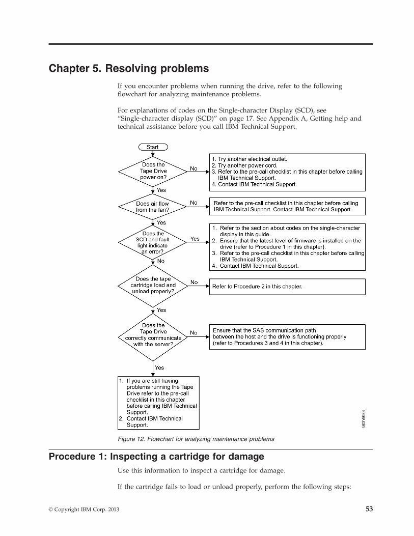
Chapter 5. Resolving problems
If you encounter problems when running the drive, refer to the followingflowchart for analyzing maintenance problems.
For explanations of codes on the Single-character Display (SCD), see“Single-character display (SCD)” on page 17. See Appendix A, Getting help andtechnical assistance before you call IBM Technical Support.
Procedure 1: Inspecting a cartridge for damageUse this information to inspect a cartridge for damage.
If the cartridge fails to load or unload properly, perform the following steps:
Figure 12. Flowchart for analyzing maintenance problems
© Copyright IBM Corp. 2013 53

1. Check that the leader pin is attached and properly seated (see “Repositioning aleader pin” on page 69) by opening the cartridge door and observing the pinplacement.
2. Inspect the cartridge case, the cartridge door, and the write-protect switch fordamage.
3. Inspect the rear of the cartridge (the part that you load first into the tape loadcompartment) and make sure that there are no gaps in the seam of thecartridge case (see “Repositioning a leader pin” on page 69 ). If there are gaps,the leader pin may be dislodged. See Appendix D, “Repairing a cartridge,” onpage 69.
4. Try loading or unloading another tape cartridge.v If the new cartridge loads or unloads properly, discard the cartridge that
originally failed.v If the new cartridge does not load or unload properly, contact your IBM
technical-support representative for additional problem determination.
Note:
1. If a damaged or mishandled cartridge is the problem, see “Handlingcartridges” on page 47 for proper instructions about handling media. It ispossible that your other cartridges may also be damaged.
2. If your cartridge does not eject properly, contact your service representative.
Procedure 2: Checking SAS host connectionsUse this information to check SAS host connections.
If your server is not communicating with the SAS drive, the problem might be theSAS cable, the SAS host adapter, or the SAS host adapter setup.
To check the compatibility of your System x hardware and options, go tohttp://www-03.ibm.com/systems/info/x86servers/serverproven/compat/us/indexsp.html.
To check the host connections for your drive, complete the following steps:1. Make sure that the tape drive power is on.2. Make sure that the SAS cable is fully-seated in the server and in the tape drive.3. Make sure that the parameters for the SAS host adapter installation are correct.4. Make sure that the SAS host adapter is supported by the tape drive.5. Make sure that there is a point-to-point connectivity between the server and the
tape drive. SAS connectivity does not support multiple drive connections (adaisy-chain of devices).
6. Check the length of the SAS cable. It must not exceed 5.5 m (18 ft).
Procedure 3: Verifying host interface communicationUse this information to verify host interface communication.
The Wrap diagnostic tests the communication function at the device interface.However, to thoroughly verify host-to-device communications, initiate activity overthe SAS interface bus from the host to the drive and back. A utility to perform thistest is the IBM TotalStorage Tape Diagnostic Tool (ITDT). ITDT is available on theIBM website at http://www.ibm.com/storage/lto.
54 IBM Half High LTO Ultrium Gen 6 Internal SAS Tape Drive: Installation and User's Guide

The ITDT is effective for updating the drive firmware and for performing the TestDevice function. For additional information about using the ITDT, see “Updatingfirmware” on page 14. To use the ITDT to execute the Test Device function,complete the following steps:1. If the ITDT utility is not installed on your server, download the applicable
version for your operating system from the IBM website into a directory onyour server.
2. When installation is complete, run the SCAN (s) option to determine if yourserver can detect all of the Ultrium tape drive devices (including any librariesor autoloaders that might be on the bus).
3. Select the drive that is to be tested or to have firmware downloaded.4. For testing, select the Test Device (t) option.
Note: This option will perform a series of LOADS, UNLOADS, andWRITE/READ operations. Both tape drive control commands and data are sentto the device over the interface bus.
5. The test will run for at least 30 minutes. If you determine that the interfacecommunication is operating correctly before test completes, enter the ABORTcommand (a).
Resolving problems reported by the serverUse this information to resolve problems reported by the server.
The procedure for fixing interface bus errors varies, depending on whether theerror is consistent or intermittent, and on your configuration. The sections thatfollow describe how to fix an error.
Fixing SAS bus errors1. Make sure that the tape drive power is on.2. Make sure that the SAS cable is fully seated in the server and the tape drive.3. Replace the SAS cable if it shows any signs of damage.
Resolving problems with the tape mediaUse this information to resolve problems with the tape media.
To resolve problems that are related to media, the drive firmware includes thefollowing capabilities:v Test Cartridge & Media diagnostic that verifies whether a suspect cartridge and
its magnetic tape are acceptable for use.v Statistical Analysis and Reporting System (SARS) to assist in isolating failures
between media and hardware. To determine the cause of failure, SARS uses thecartridge performance history that is saved in the cartridge memory (CM) andthe drive performance history that is kept in the drive VPD (Vital Product Data)area in NVRAM. Any failures that SARS detects are reported as TapeAlert flagson the server (see IBM LTO Ultrium Tape Drive SCSI Reference athttp://www-01.ibm.com/support/docview.wss?uid=ssg1S7001045&aid=1.).Attention: If you insert the IBM LTO Ultrium Data Cartridge into anothermanufacturer's drive, the SARS data in the cartridge memory might become lostor invalid.
Chapter 5. Resolving problems 55
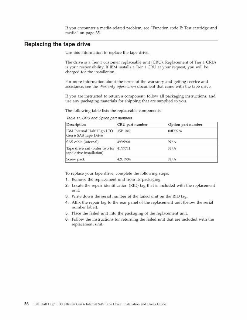
If you encounter a media-related problem, see “Function code E: Test cartridge andmedia” on page 35.
Replacing the tape driveUse this information to replace the tape drive.
The drive is a Tier 1 customer replaceable unit (CRU). Replacement of Tier 1 CRUsis your responsibility. If IBM installs a Tier 1 CRU at your request, you will becharged for the installation.
For more information about the terms of the warranty and getting service andassistance, see the Warranty information document that came with the tape drive.
If you are instructed to return a component, follow all packaging instructions, anduse any packaging materials for shipping that are supplied to you.
The following table lists the replaceable components.
Table 11. CRU and Option part numbers
Description CRU part number Option part number
IBM Internal Half High LTOGen 6 SAS Tape Drive
35P1049 00D8924
SAS cable (internal) 49Y9901 N/A
Tape drive rail (order two fortape drive installation)
41Y7711 N/A
Screw pack 42C3934 N/A
To replace your tape drive, complete the following steps:1. Remove the replacement unit from its packaging.2. Locate the repair identification (RID) tag that is included with the replacement
unit.3. Write down the serial number of the failed unit on the RID tag.4. Affix the repair tag to the rear panel of the replacement unit (below the serial
number label).5. Place the failed unit into the packaging of the replacement unit.6. Follow the instructions for returning the failed unit that are included with the
replacement unit.
56 IBM Half High LTO Ultrium Gen 6 Internal SAS Tape Drive: Installation and User's Guide
Appendix A. Getting help and technical assistance
If you need help, service, or technical assistance or just want more informationabout IBM products, you will find a wide variety of sources available from IBM toassist you.
Use this information to obtain additional information about IBM and IBMproducts, determine what to do if you experience a problem with your IBM systemor optional device, and determine whom to call for service, if it is necessary.
Before you callBefore you call, make sure that you have taken these steps to try to solve theproblem yourself.
If you believe that you require IBM to perform warranty service on your IBMproduct, the IBM service technicians will be able to assist you more efficiently ifyou prepare before you call.v Check all cables to make sure that they are connected.v Check the power switches to make sure that the system and any optional
devices are turned on.v Check for updated software, firmware, and operating-system device drivers for
your IBM product. The IBM Warranty terms and conditions state that you, theowner of the IBM product, are responsible for maintaining and updating allsoftware and firmware for the product (unless it is covered by an additionalmaintenance contract). Your IBM service technician will request that youupgrade your software and firmware if the problem has a documented solutionwithin a software upgrade.
v If you have installed new hardware or software in your environment, check tomake sure that the hardware and software is supported by your IBM product.
v Go to to check for information to help you solve the problem.v Gather the following information to provide to IBM Support. This data will help
IBM Support quickly provide a solution to your problem and ensure that youreceive the level of service for which you might have contracted.– Hardware and Software Maintenance agreement contract numbers, if
applicable– Machine type number (IBM 4-digit machine identifier)– Model number– Serial number– Current system UEFI and firmware levels– Other pertinent information such as error messages and logs
v Go to to submit an Electronic Service Request. Submitting an Electronic ServiceRequest will start the process of determining a solution to your problem bymaking the pertinent information available to IBM Support quickly andefficiently. IBM service technicians can start working on your solution as soon asyou have completed and submitted an Electronic Service Request.
You can solve many problems without outside assistance by following thetroubleshooting procedures that IBM provides in the online help or in the
© Copyright IBM Corp. 2013 57

documentation that is provided with your IBM product. The documentation thatcomes with IBM systems also describes the diagnostic tests that you can perform.Most systems, operating systems, and programs come with documentation thatcontains troubleshooting procedures and explanations of error messages and errorcodes. If you suspect a software problem, see the documentation for the operatingsystem or program.
Using the documentationInformation about your IBM system and preinstalled software, if any, or optionaldevice is available in the documentation that comes with the product. Thatdocumentation can include printed documents, online documents, readme files,and help files.
See the troubleshooting information in your system documentation for instructionsfor using the diagnostic programs. The troubleshooting information or thediagnostic programs might tell you that you need additional or updated devicedrivers or other software. IBM maintains pages on the World Wide Web where youcan get the latest technical information and download device drivers and updates.To access these pages, go to .
Getting help and information from the World Wide WebUp-to-date information about IBM products and support is available on the WorldWide Web.
On the World Wide Web, up-to-date information about IBM systems, optionaldevices, services, and support is available at . IBM System x information is at . IBMBladeCenter information is at . IBM IntelliStation information is at .
How to send DSA data to IBMUse the IBM Enhanced Customer Data Repository to send diagnostic data to IBM.
Before you send diagnostic data to IBM, read the terms of use at .
You can use any of the following methods to send diagnostic data to IBM:v Standard upload:
v Standard upload with the system serial number:
v Secure upload:
v Secure upload with the system serial number:
Creating a personalized support web pageYou can create a personalized support web page by identifying IBM products thatare of interest to you.
To create a personalized support web page, go to . From this personalized page,you can subscribe to weekly email notifications about new technical documents,search for information and downloads, and access various administrative services.
Software service and supportThrough IBM Support Line, you can get telephone assistance, for a fee, with usage,configuration, and software problems with your IBM products.
58 IBM Half High LTO Ultrium Gen 6 Internal SAS Tape Drive: Installation and User's Guide
For more information about Support Line and other IBM services, see or see forsupport telephone numbers. In the U.S. and Canada, call 1-800-IBM-SERV(1-800-426-7378).
Hardware service and supportYou can receive hardware service through your IBM reseller or IBM Services.
To locate a reseller authorized by IBM to provide warranty service, go to and clickFind Business Partners on the right side of the page. For IBM support telephonenumbers, see . In the U.S. and Canada, call 1-800-IBM-SERV (1-800-426-7378).
In the U.S. and Canada, hardware service and support is available 24 hours a day,7 days a week. In the U.K., these services are available Monday through Friday,from 9 a.m. to 6 p.m.
IBM Taiwan product serviceUse this information to contact IBM Taiwan product service.
IBM Taiwan product service contact information:
IBM Taiwan Corporation3F, No 7, Song Ren Rd.Taipei, TaiwanTelephone: 0800-016-888
Appendix A. Getting help and technical assistance 59

60 IBM Half High LTO Ultrium Gen 6 Internal SAS Tape Drive: Installation and User's Guide

Appendix B. TapeAlert flags
TapeAlert is a patented technology and standard of the American NationalStandards Institute (ANSI) that defines conditions and problems that areexperienced by tape drives. The technology enables a server to read TapeAlertflags from a tape drive through the host interface. The server reads the flags fromLog Sense Page 0x2E. See the IBM LTO Ultrium Tape Drive SCSI Reference documentfor the list of TapeAlert flags that are supported by this tape drive. To downloadthe IBM LTO Ultrium Tape Drive SCSI Reference document (PDF), go tohttp://www-01.ibm.com/support/docview.wss?uid=ssg1S7001045&aid=1.
© Copyright IBM Corp. 2013 61

62 IBM Half High LTO Ultrium Gen 6 Internal SAS Tape Drive: Installation and User's Guide

Appendix C. Error codes and messages
If the drive detects a permanent error, it will display the error code on the SCDand flash the amber fault light (green status light will be off).v Make note of the SCD error code prior to removing a cartridge or clearing the
SCD error code.v If an error occurred with a cartridge in the drive, push the Unload button to
eject the cartridge.v To clear the SCD error code and power cycle the drive, press the Unload button
for ten seconds. A drive dump will be created.
Attention: If the drive detects a permanent error and displays an error code other
than , it automatically performs a drive dump. If you force a drive dump, theexisting dump will be overwritten and data will be lost. After you force a drivedump, do not turn off the power to the drive or you might lose the dump data.
Table 12. Error codes on the SCD
Error code Cause and action
No error occurred and no action is required. This code displays when diagnostics have finishedrunning and no error occurred.Note: The SCD is blank during normal operation of the tape drive.
Temperature problem. The tape drive detected that the recommended operating temperature wasexceeded. Perform one or more of the following actions:
v Make sure that the cooling fan is rotating and is quiet. If it is not, see the documentation thatcame with your enclosure or server.
v Remove any blockage that prevents air from flowing freely through the tape drive.
v Make sure that the operating temperature and airflow is within the specified range.Specifications for tape cartridges are given in “Environmental and shipping specifications fortape cartridges” on page 50.
Clear the error code by turning off and turning on the tape drive power or placing the drive inMaintenance mode. If the operating temperature and airflow are within the specified range, andthe problem persists, replace the drive.
Power problem. The tape drive detected that the externally supplied power is outside thespecified voltage limits (the tape drive is not operating). Complete the following steps:
1. Make sure that the power connector is properly seated.
2. Make sure that the proper dc voltages are being applied within the tolerances allowed.Specifications for tape cartridges are given in “Environmental and shipping specifications fortape cartridges” on page 50.
3. If the proper voltages are not being applied, service the power supply.
4. If the proper voltages are being applied, turn off and turn on the tape drive power to see if theproblem repeats.
5. Replace the tape drive if the problem persists.
The error code clears when you place the tape drive in Maintenance mode.
© Copyright IBM Corp. 2013 63
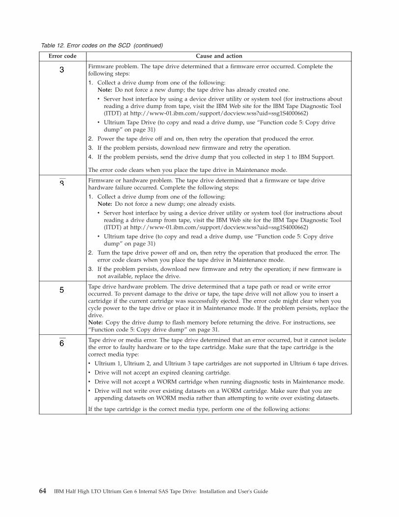
Table 12. Error codes on the SCD (continued)
Error code Cause and action
Firmware problem. The tape drive determined that a firmware error occurred. Complete thefollowing steps:
1. Collect a drive dump from one of the following:Note: Do not force a new dump; the tape drive has already created one.
v Server host interface by using a device driver utility or system tool (for instructions aboutreading a drive dump from tape, visit the IBM Web site for the IBM Tape Diagnostic Tool(ITDT) at http://www-01.ibm.com/support/docview.wss?uid=ssg1S4000662)
v Ultrium Tape Drive (to copy and read a drive dump, use “Function code 5: Copy drivedump” on page 31)
2. Power the tape drive off and on, then retry the operation that produced the error.
3. If the problem persists, download new firmware and retry the operation.
4. If the problem persists, send the drive dump that you collected in step 1 to IBM Support.
The error code clears when you place the tape drive in Maintenance mode.
Firmware or hardware problem. The tape drive determined that a firmware or tape drivehardware failure occurred. Complete the following steps:
1. Collect a drive dump from one of the following:Note: Do not force a new dump; one already exists.
v Server host interface by using a device driver utility or system tool (for instructions aboutreading a drive dump from tape, visit the IBM Web site for the IBM Tape Diagnostic Tool(ITDT) at http://www-01.ibm.com/support/docview.wss?uid=ssg1S4000662)
v Ultrium tape drive (to copy and read a drive dump, use “Function code 5: Copy drivedump” on page 31)
2. Turn the tape drive power off and on, then retry the operation that produced the error. Theerror code clears when you place the tape drive in Maintenance mode.
3. If the problem persists, download new firmware and retry the operation; if new firmware isnot available, replace the drive.
Tape drive hardware problem. The drive determined that a tape path or read or write erroroccurred. To prevent damage to the drive or tape, the tape drive will not allow you to insert acartridge if the current cartridge was successfully ejected. The error code might clear when youcycle power to the tape drive or place it in Maintenance mode. If the problem persists, replace thedrive.Note: Copy the drive dump to flash memory before returning the drive. For instructions, see“Function code 5: Copy drive dump” on page 31.
Tape drive or media error. The tape drive determined that an error occurred, but it cannot isolatethe error to faulty hardware or to the tape cartridge. Make sure that the tape cartridge is thecorrect media type:
v Ultrium 1, Ultrium 2, and Ultrium 3 tape cartridges are not supported in Ultrium 6 tape drives.
v Drive will not accept an expired cleaning cartridge.
v Drive will not accept a WORM cartridge when running diagnostic tests in Maintenance mode.
v Drive will not write over existing datasets on a WORM cartridge. Make sure that you areappending datasets on WORM media rather than attempting to write over existing datasets.
If the tape cartridge is the correct media type, perform one of the following actions:
64 IBM Half High LTO Ultrium Gen 6 Internal SAS Tape Drive: Installation and User's Guide

Table 12. Error codes on the SCD (continued)
Error code Cause and action
For Problems with Writing Data:
If the problem occurred while the tape drive was writing data to the tape, retry the operation witha different cartridge:v If the operation succeeds, the original cartridge was defective. Copy the data from the defective
cartridge and discard it according to the security policy for your organization.v If the operation fails and another tape drive is available, insert the cartridge into the other unit
and retry the operation.– If the operation fails, discard the defective cartridge according to the security policy for your
organization.– If the operation succeeds, insert a scratch data cartridge into the first unit and run “Function
code 1: Run drive diagnostics” on page 28.- If the diagnostics fail, replace the tape drive.- If the diagnostics succeed, the error was temporary.
v If the operation fails and another tape drive is not available, insert a scratch (blank) datacartridge into the unit and run “Function code 1: Run drive diagnostics” on page 28.– If the diagnostics fail, replace the tape drive.– If the diagnostics succeed, discard the cartridge according to the security policy for your
organization.
If the problem occurs with multiple tape cartridges, run “Function code 1: Run drive diagnostics”on page 28:v If the diagnostics fail, replace the tape drive.v If the diagnostics succeed, run “Function code H: Test head” on page 37.
– If the diagnostic fails, replace the tape drive.– If the diagnostic succeeds, replace the cartridges that caused the problem.
The error code clears when you remove the tape cartridge or place the tape drive in Maintenancemode.
For Problems with Reading Data:
If the problem occurred while the tape drive was reading data from the tape, perform one of thefollowing procedures:v If another tape drive is available, insert the cartridge into the other unit and retry the operation:
– If the operation fails, discard the defective cartridge according to the security policy for yourorganization.
– If the operation succeeds, insert a scratch data cartridge into the first unit and run “Functioncode 1: Run drive diagnostics” on page 28:- If the diagnostic fails, replace the tape drive.- If the diagnostic succeeds, the error was temporary.
v If another tape drive is not available, insert a scratch data cartridge into the unit and run“Function code 1: Run drive diagnostics” on page 28:– If the diagnostic fails, replace the tape drive.– If the diagnostic succeeds, discard the cartridge according to the security policy for your
organization.
If the problem occurs with multiple tape cartridges, run “Function code 1: Run drive diagnostics”on page 28:v If the diagnostic fails, replace the tape drive.v If the diagnostic succeeds, run “Function code H: Test head” on page 37.
– If the diagnostic fails, replace the tape drive.– If the diagnostic succeeds, replace the cartridges that caused the problem.
The error code clears when you remove the tape cartridge or place the tape drive in Maintenancemode.
Appendix C. Error codes and messages 65
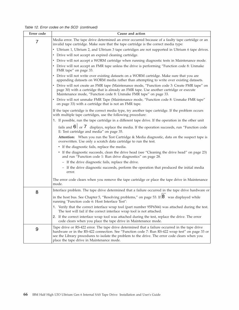
Table 12. Error codes on the SCD (continued)
Error code Cause and action
Media error. The tape drive determined an error occurred because of a faulty tape cartridge or aninvalid tape cartridge. Make sure that the tape cartridge is the correct media type:
v Ultrium 1, Ultrium 2, and Ultrium 3 tape cartridges are not supported in Ultrium 6 tape drives.
v Drive will not accept an expired cleaning cartridge.
v Drive will not accept a WORM cartridge when running diagnostic tests in Maintenance mode.
v Drive will not accept an FMR tape unless the drive is performing “Function code 8: UnmakeFMR tape” on page 33.
v Drive will not write over existing datasets on a WORM cartridge. Make sure that you areappending datasets on WORM media rather than attempting to write over existing datasets.
v Drive will not create an FMR tape (Maintenance mode, “Function code 3: Create FMR tape” onpage 30) with a cartridge that is already an FMR tape. Use another cartridge or executeMaintenance mode, “Function code 8: Unmake FMR tape” on page 33.
v Drive will not unmake FMR Tape (Maintenance mode, “Function code 8: Unmake FMR tape”on page 33) with a cartridge that is not an FMR tape.
If the tape cartridge is the correct media type, try another tape cartridge. If the problem occurswith multiple tape cartridges, use the following procedure:
1. If possible, run the tape cartridge in a different tape drive. If the operation in the other unit
fails and or displays, replace the media. If the operation succeeds, run “Function codeE: Test cartridge and media” on page 35.
Attention: When you run the Test Cartridge & Media diagnostic, data on the suspect tape isoverwritten. Use only a scratch data cartridge to run the test.
v If the diagnostic fails, replace the media.
v If the diagnostic succeeds, clean the drive head (see “Cleaning the drive head” on page 23)and run “Function code 1: Run drive diagnostics” on page 28.
– If the drive diagnostic fails, replace the drive.
– If the drive diagnostic succeeds, perform the operation that produced the initial mediaerror.
The error code clears when you remove the tape cartridge or place the tape drive in Maintenancemode.
Interface problem. The tape drive determined that a failure occurred in the tape drive hardware or
in the host bus. See Chapter 5, “Resolving problems,” on page 53. If was displayed whilerunning "Function code 6: Host Interface Test":
1. Verify that the correct interface wrap tool (part number 95P6566) was attached during the test.The test will fail if the correct interface wrap tool is not attached.
2. If the correct interface wrap tool was attached during the test, replace the drive. The errorcode clears when you place the tape drive in Maintenance mode.
Tape drive or RS-422 error. The tape drive determined that a failure occurred in the tape drivehardware or in the RS-422 connection. See “Function code 7: Run RS-422 wrap test” on page 33 orsee the Library procedures to isolate the problem to the drive. The error code clears when youplace the tape drive in Maintenance mode.
66 IBM Half High LTO Ultrium Gen 6 Internal SAS Tape Drive: Installation and User's Guide
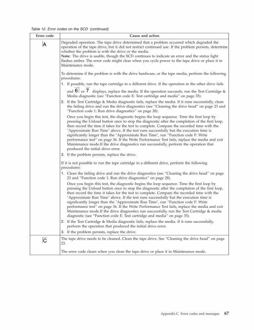
Table 12. Error codes on the SCD (continued)
Error code Cause and action
Degraded operation. The tape drive determined that a problem occurred which degraded theoperation of the tape drive, but it did not restrict continued use. If the problem persists, determinewhether the problem is with the drive or the media.Note: The drive is usable, though the SCD continues to indicate an error and the status lightflashes amber. The error code might clear when you cycle power to the tape drive or place it inMaintenance mode.
To determine if the problem is with the drive hardware, or the tape media, perform the followingprocedures:
1. If possible, run the tape cartridge in a different drive. If the operation in the other drive fails
and or displays, replace the media. If the operation succeeds, run the Test Cartridge &Media diagnostic (see “Function code E: Test cartridge and media” on page 35).
2. If the Test Cartridge & Media diagnostic fails, replace the media. If it runs successfully, cleanthe failing drive and run the drive diagnostics (see “Cleaning the drive head” on page 23 and“Function code 1: Run drive diagnostics” on page 28).
Once you begin this test, the diagnostic begins the loop sequence. Time the first loop bypressing the Unload button once to stop the diagnostic after the completion of the first loop,then record the time it takes for the test to complete. Compare the recorded time with the"Approximate Run Time" above. If the test runs successfully but the execution time issignificantly longer than the "Approximate Run Time", run “Function code F: Writeperformance test” on page 36. If the Write Performance Test fails, replace the media and exitMaintenance mode.If the drive diagnostics run successfully, perform the operation thatproduced the initial drive error.
3. If the problem persists, replace the drive.
If it is not possible to run the tape cartridge in a different drive, perform the followingprocedures:
1. Clean the failing drive and run the drive diagnostics (see “Cleaning the drive head” on page23 and “Function code 1: Run drive diagnostics” on page 28).
Once you begin this test, the diagnostic begins the loop sequence. Time the first loop bypressing the Unload button once to stop the diagnostic after the completion of the first loop,then record the time it takes for the test to complete. Compare the recorded time with the"Approximate Run Time" above. If the test runs successfully but the execution time issignificantly longer than the "Approximate Run Time", run “Function code F: Writeperformance test” on page 36. If the Write Performance Test fails, replace the media and exitMaintenance mode.If the drive diagnostics run successfully, run the Test Cartridge & mediadiagnostic (see “Function code E: Test cartridge and media” on page 35).
2. If the Test Cartridge & Media diagnostic fails, replace the media. If it runs successfully,perform the operation that produced the initial drive error.
3. If the problem persists, replace the drive.
The tape drive needs to be cleaned. Clean the tape drive. See “Cleaning the drive head” on page23.
The error code clears when you clean the tape drive or place it in Maintenance mode.
Appendix C. Error codes and messages 67
Table 12. Error codes on the SCD (continued)
Error code Cause and action
Encryption error. Displayed when the drive detects an error associated with a encryptionoperation. If the problem occurred while the tape drive was writing data to, or reading data from,tape:
1. Check the host application to make sure that the host application is providing the correctencryption key.
v See the IBM Tape Device Drivers Encryption Support documentation and the IBM LTO UltriumTape Drive SCSI Reference documentation for the Sense Data returned for an encryptionoperation.
v Retry the encryption operation after the host application problems have been resolved.
2. Check the operation of the tape drive by resetting the drive and running POST. See Table 7 onpage 21.
v See the error code displayed on the SCD if the drive reset and POST fails.
v Retry the encryption operation if the drive reset and POST complete without errors.
3. Check the media.
v Make sure that the correct media is being used. Data encryption is supported with LTOUltrium 4, 5 and 6 data cartridges only.
v Retry the encryption operation with the tape cartridge in another encryption enabled drive.Replace the media if the problem repeats with the same tape cartridge in multiple drives.
If the problem occurred while the tape drive was running POST or diagnostics, replace the drive.
The error code clears with the first attempted write/read after the encryption key is changed, orwhen the drive is placed in Maintenance mode.
Incompatible media. The tape drive detected an unsupported cartridge was loaded or thecartridge loaded has an incompatible format. Ultrium 1, 2 and 3 cartridges are not supported inthe Ultrium 6 tape drive.
Write operation to a write protected cartridge has been attempted (this includes any attempt tooverwrite a WORM protected tape). Make sure that the tape cartridge is the correct media type.Writes to Ultrium 1, 2, 3 or 4 tape cartridges are not supported in the Ultrium 6 tape drives. If thetape cartridge is the correct media type, check the write-protect switch on the cartridge. The drivewill not write to a write-protected cartridge. The error code clears when you remove the tapecartridge or place the tape drive in Maintenance mode.
68 IBM Half High LTO Ultrium Gen 6 Internal SAS Tape Drive: Installation and User's Guide
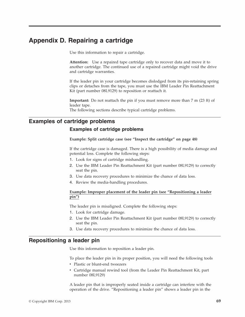
Appendix D. Repairing a cartridge
Use this information to repair a cartridge.
Attention: Use a repaired tape cartridge only to recover data and move it toanother cartridge. The continued use of a repaired cartridge might void the driveand cartridge warranties.
If the leader pin in your cartridge becomes dislodged from its pin-retaining springclips or detaches from the tape, you must use the IBM Leader Pin ReattachmentKit (part number 08L9129) to reposition or reattach it.
Important: Do not reattach the pin if you must remove more than 7 m (23 ft) ofleader tape.The following sections describe typical cartridge problems.
Examples of cartridge problemsExamples of cartridge problems
Example: Split cartridge case (see “Inspect the cartridge” on page 48)
If the cartridge case is damaged. There is a high possibility of media damage andpotential loss. Complete the following steps:1. Look for signs of cartridge mishandling.2. Use the IBM Leader Pin Reattachment Kit (part number 08L9129) to correctly
seat the pin.3. Use data recovery procedures to minimize the chance of data loss.4. Review the media-handling procedures.
Example: Improper placement of the leader pin (see “Repositioning a leaderpin”)
The leader pin is misaligned. Complete the following steps:1. Look for cartridge damage.2. Use the IBM Leader Pin Reattachment Kit (part number 08L9129) to correctly
seat the pin.3. Use data recovery procedures to minimize the chance of data loss.
Repositioning a leader pinUse this information to reposition a leader pin.
To place the leader pin in its proper position, you will need the following toolsv Plastic or blunt-end tweezersv Cartridge manual rewind tool (from the Leader Pin Reattachment Kit, part
number 08L9129)
A leader pin that is improperly seated inside a cartridge can interfere with theoperation of the drive. “Repositioning a leader pin” shows a leader pin in the
© Copyright IBM Corp. 2013 69
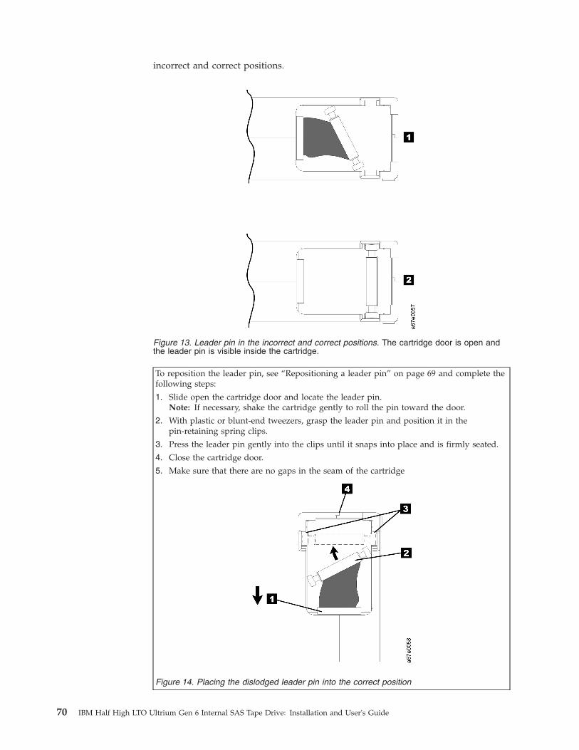
incorrect and correct positions.
To reposition the leader pin, see “Repositioning a leader pin” on page 69 and complete thefollowing steps:
1. Slide open the cartridge door and locate the leader pin.Note: If necessary, shake the cartridge gently to roll the pin toward the door.
2. With plastic or blunt-end tweezers, grasp the leader pin and position it in thepin-retaining spring clips.
3. Press the leader pin gently into the clips until it snaps into place and is firmly seated.
4. Close the cartridge door.
5. Make sure that there are no gaps in the seam of the cartridge
Figure 14. Placing the dislodged leader pin into the correct position
Figure 13. Leader pin in the incorrect and correct positions. The cartridge door is open andthe leader pin is visible inside the cartridge.
70 IBM Half High LTO Ultrium Gen 6 Internal SAS Tape Drive: Installation and User's Guide
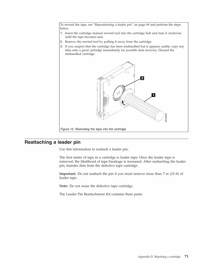
To rewind the tape, see “Repositioning a leader pin” on page 69 and perform the stepsbelow.
1. Insert the cartridge manual rewind tool into the cartridge hub and turn it clockwiseuntil the tape becomes taut.
2. Remove the rewind tool by pulling it away from the cartridge.
3. If you suspect that the cartridge has been mishandled but it appears usable, copy anydata onto a good cartridge immediately for possible data recovery. Discard themishandled cartridge.
Figure 15. Rewinding the tape into the cartridge
Reattaching a leader pinUse this information to reattach a leader pin.
The first meter of tape in a cartridge is leader tape. Once the leader tape isremoved, the likelihood of tape breakage is increased. After reattaching the leaderpin, transfer data from the defective tape cartridge.
Important: Do not reattach the pin if you must remove more than 7 m (23 ft) ofleader tape.
Note: Do not reuse the defective tape cartridge.
The Leader Pin Reattachment Kit contains three parts:
Appendix D. Repairing a cartridge 71

The parts included in the Leader Pin Reattachment Kit are:
Leader pin attach toolA plastic brace that holds the cartridge door open.
Cartridge manual rewind toolA device that fits into the cartridge hub and lets you wind the tape intoand out of the cartridge.
Leader pinsExtra leader pins are included.
C-clipsExtra C-clips are included.
Figure 16. Leader Pin Reattachment Kit
72 IBM Half High LTO Ultrium Gen 6 Internal SAS Tape Drive: Installation and User's Guide

Attention:
v Use only the IBM Leader Pin Reattachment Kit to reattach the leader pin to thetape. Other methods of reattaching the pin will damage the tape, the drive, orboth, and might void the tape drive warranty.
v Use this procedure on your tape cartridge only when the leader pin detachesfrom the magnetic tape and you must copy the cartridge data onto anothercartridge. After you copy the data, destroy the damaged cartridge according tothe security policy for your organization. This procedure might affect theperformance of the leader pin during threading and unloading operations.
v Touch only the end of the tape. Touching the tape in an area other than the endcan damage the tape surface or edges, which might interfere with read or writereliability.
To reattach a leader pin by using the IBM Leader Pin Reattachment Kit, see Figure 17 andperform the steps below.
1. Attach the leader pin attach tool to the cartridge so that the hook latches into thecartridge door.
2. Pull the tool back to hold the door open, then slide the tool onto the cartridge. Open thetool pivot arm.
Figure 17. Attaching the leader pin attach tool to the cartridge
Appendix D. Repairing a cartridge 73
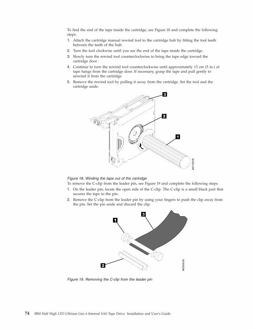
To find the end of the tape inside the cartridge, see Figure 18 and complete the followingsteps:
1. Attach the cartridge manual rewind tool to the cartridge hub by fitting the tool teethbetween the teeth of the hub.
2. Turn the tool clockwise until you see the end of the tape inside the cartridge.
3. Slowly turn the rewind tool counterclockwise to bring the tape edge toward thecartridge door .
4. Continue to turn the rewind tool counterclockwise until approximately 13 cm (5 in.) oftape hangs from the cartridge door. If necessary, grasp the tape and pull gently tounwind it from the cartridge.
5. Remove the rewind tool by pulling it away from the cartridge. Set the tool and thecartridge aside.
Figure 18. Winding the tape out of the cartridgeTo remove the C-clip from the leader pin, see Figure 19 and complete the following steps:
1. On the leader pin, locate the open side of the C-clip. The C-clip is a small black part thatsecures the tape to the pin.
2. Remove the C-clip from the leader pin by using your fingers to push the clip away fromthe pin. Set the pin aside and discard the clip.
Figure 19. Removing the C-clip from the leader pin
74 IBM Half High LTO Ultrium Gen 6 Internal SAS Tape Drive: Installation and User's Guide
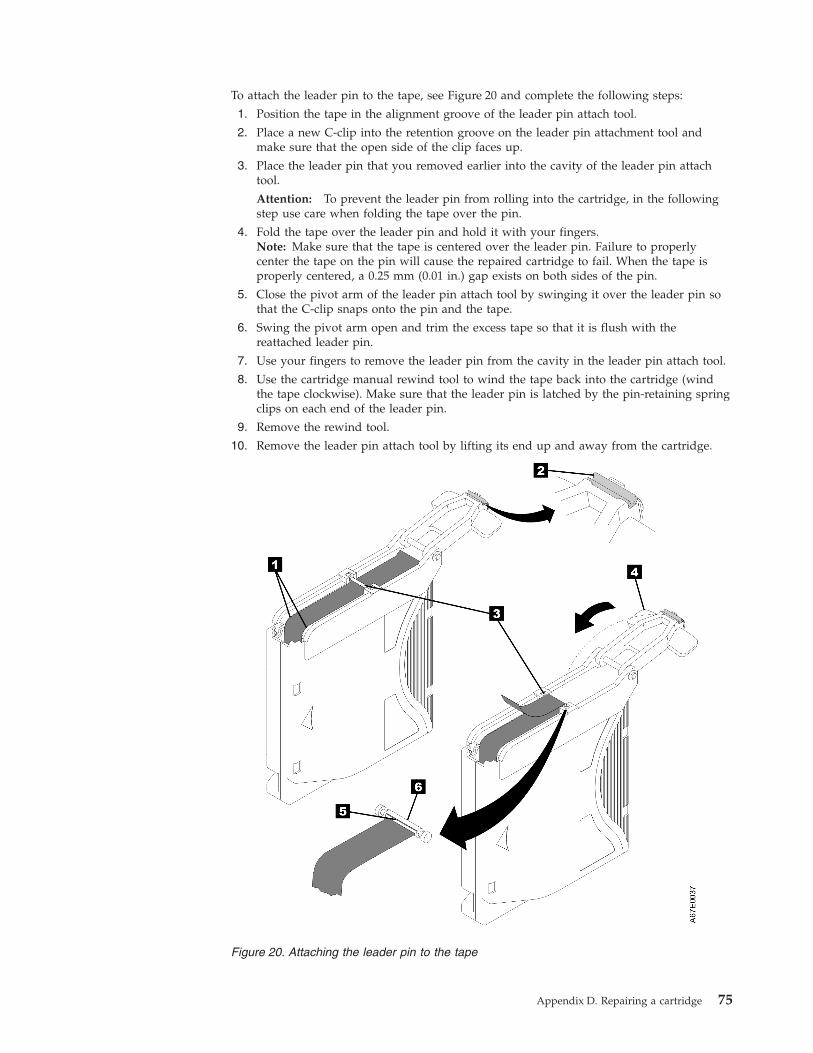
To attach the leader pin to the tape, see Figure 20 and complete the following steps:
1. Position the tape in the alignment groove of the leader pin attach tool.
2. Place a new C-clip into the retention groove on the leader pin attachment tool andmake sure that the open side of the clip faces up.
3. Place the leader pin that you removed earlier into the cavity of the leader pin attachtool.
Attention: To prevent the leader pin from rolling into the cartridge, in the followingstep use care when folding the tape over the pin.
4. Fold the tape over the leader pin and hold it with your fingers.Note: Make sure that the tape is centered over the leader pin. Failure to properlycenter the tape on the pin will cause the repaired cartridge to fail. When the tape isproperly centered, a 0.25 mm (0.01 in.) gap exists on both sides of the pin.
5. Close the pivot arm of the leader pin attach tool by swinging it over the leader pin sothat the C-clip snaps onto the pin and the tape.
6. Swing the pivot arm open and trim the excess tape so that it is flush with thereattached leader pin.
7. Use your fingers to remove the leader pin from the cavity in the leader pin attach tool.
8. Use the cartridge manual rewind tool to wind the tape back into the cartridge (windthe tape clockwise). Make sure that the leader pin is latched by the pin-retaining springclips on each end of the leader pin.
9. Remove the rewind tool.
10. Remove the leader pin attach tool by lifting its end up and away from the cartridge.
Figure 20. Attaching the leader pin to the tape
Appendix D. Repairing a cartridge 75

76 IBM Half High LTO Ultrium Gen 6 Internal SAS Tape Drive: Installation and User's Guide

Notices
This information was developed for products and services offered in the U.S.A.
IBM may not offer the products, services, or features discussed in this document inother countries. Consult your local IBM representative for information on theproducts and services currently available in your area. Any reference to an IBMproduct, program, or service is not intended to state or imply that only that IBMproduct, program, or service may be used. Any functionally equivalent product,program, or service that does not infringe any IBM intellectual property right maybe used instead. However, it is the user's responsibility to evaluate and verify theoperation of any non-IBM product, program, or service.
IBM may have patents or pending patent applications covering subject matterdescribed in this document. The furnishing of this document does not give youany license to these patents. You can send license inquiries, in writing, to:
IBM Director of LicensingIBM CorporationNorth Castle DriveArmonk, NY 10504-1785U.S.A.
INTERNATIONAL BUSINESS MACHINES CORPORATION PROVIDES THISPUBLICATION “AS IS” WITHOUT WARRANTY OF ANY KIND, EITHEREXPRESS OR IMPLIED, INCLUDING, BUT NOT LIMITED TO, THE IMPLIEDWARRANTIES OF NON-INFRINGEMENT, MERCHANTABILITY OR FITNESSFOR A PARTICULAR PURPOSE. Some states do not allow disclaimer of express orimplied warranties in certain transactions, therefore, this statement may not applyto you.
This information could include technical inaccuracies or typographical errors.Changes are periodically made to the information herein; these changes will beincorporated in new editions of the publication. IBM may make improvementsand/or changes in the product(s) and/or the program(s) described in thispublication at any time without notice.
Any references in this information to non-IBM websites are provided forconvenience only and do not in any manner serve as an endorsement of thosewebsites. The materials at those websites are not part of the materials for this IBMproduct, and use of those websites is at your own risk.
IBM may use or distribute any of the information you supply in any way itbelieves appropriate without incurring any obligation to you.
TrademarksIBM, the IBM logo, and ibm.com are trademarks of International BusinessMachines Corp., registered in many jurisdictions worldwide. Other product andservice names might be trademarks of IBM or other companies.
A current list of IBM trademarks is available on the web at .
© Copyright IBM Corp. 2013 77

Adobe and PostScript are either registered trademarks or trademarks of AdobeSystems Incorporated in the United States and/or other countries.
Cell Broadband Engine is a trademark of Sony Computer Entertainment, Inc., inthe United States, other countries, or both and is used under license therefrom.
Intel, Intel Xeon, Itanium, and Pentium are trademarks or registered trademarks ofIntel Corporation or its subsidiaries in the United States and other countries.
Java and all Java-based trademarks and logos are trademarks or registeredtrademarks of Oracle and/or its affiliates.
Linux is a registered trademark of Linus Torvalds in the United States, othercountries, or both.
Microsoft, Windows, and Windows NT are trademarks of Microsoft Corporation inthe United States, other countries, or both.
UNIX is a registered trademark of The Open Group in the United States and othercountries.
Important notesProcessor speed indicates the internal clock speed of the microprocessor; otherfactors also affect application performance.
CD or DVD drive speed is the variable read rate. Actual speeds vary and are oftenless than the possible maximum.
When referring to processor storage, real and virtual storage, or channel volume,KB stands for 1024 bytes, MB stands for 1,048,576 bytes, and GB stands for1,073,741,824 bytes.
When referring to hard disk drive capacity or communications volume, MB standsfor 1,000,000 bytes, and GB stands for 1,000,000,000 bytes. Total user-accessiblecapacity can vary depending on operating environments.
Maximum internal hard disk drive capacities assume the replacement of anystandard hard disk drives and population of all hard disk drive bays with thelargest currently supported drives that are available from IBM.
Maximum memory might require replacement of the standard memory with anoptional memory module.
Each solid-state memory cell has an intrinsic, finite number of write cycles that thecell can incur. Therefore, a solid-state device has a maximum number of writecycles that it can be subjected to, expressed as “total bytes written” (TBW). Adevice that has exceeded this limit might fail to respond to system-generatedcommands or might be incapable of being written to. IBM is not responsible forreplacement of a device that has exceeded its maximum guaranteed number ofprogram/erase cycles, as documented in the Official Published Specifications forthe device.
78 IBM Half High LTO Ultrium Gen 6 Internal SAS Tape Drive: Installation and User's Guide

IBM makes no representation or warranties regarding non-IBM products andservices that are ServerProven®, including but not limited to the implied warrantiesof merchantability and fitness for a particular purpose. These products are offeredand warranted solely by third parties.
IBM makes no representations or warranties with respect to non-IBM products.Support (if any) for the non-IBM products is provided by the third party, not IBM.
Some software might differ from its retail version (if available) and might notinclude user manuals or all program functionality.
Particulate contaminationAttention: Airborne particulates (including metal flakes or particles) and reactivegases acting alone or in combination with other environmental factors such ashumidity or temperature might pose a risk to the device that is described in thisdocument.
Risks that are posed by the presence of excessive particulate levels orconcentrations of harmful gases include damage that might cause the device tomalfunction or cease functioning altogether. This specification sets forth limits forparticulates and gases that are intended to avoid such damage. The limits must notbe viewed or used as definitive limits, because numerous other factors, such astemperature or moisture content of the air, can influence the impact of particulatesor environmental corrosives and gaseous contaminant transfer. In the absence ofspecific limits that are set forth in this document, you must implement practicesthat maintain particulate and gas levels that are consistent with the protection ofhuman health and safety. If IBM determines that the levels of particulates or gasesin your environment have caused damage to the device, IBM may conditionprovision of repair or replacement of devices or parts on implementation ofappropriate remedial measures to mitigate such environmental contamination.Implementation of such remedial measures is a customer responsibility.
Table 13. Limits for particulates and gases
Contaminant Limits
Particulate v The room air must be continuously filtered with 40% atmosphericdust spot efficiency (MERV 9) according to ASHRAE Standard 52.21.
v Air that enters a data center must be filtered to 99.97% efficiency orgreater, using high-efficiency particulate air (HEPA) filters that meetMIL-STD-282.
v The deliquescent relative humidity of the particulate contaminationmust be more than 60%2.
v The room must be free of conductive contamination such as zincwhiskers.
Gaseous v Copper: Class G1 as per ANSI/ISA 71.04-19853
v Silver: Corrosion rate of less than 300 Å in 30 days
Notices 79

Table 13. Limits for particulates and gases (continued)
Contaminant Limits1 ASHRAE 52.2-2008 - Method of Testing General Ventilation Air-Cleaning Devices for RemovalEfficiency by Particle Size. Atlanta: American Society of Heating, Refrigerating andAir-Conditioning Engineers, Inc.
2 The deliquescent relative humidity of particulate contamination is the relative humidity atwhich the dust absorbs enough water to become wet and promote ionic conduction.
3 ANSI/ISA-71.04-1985. Environmental conditions for process measurement and control systems:Airborne contaminants. Instrument Society of America, Research Triangle Park, NorthCarolina, U.S.A.
Documentation formatThe publications for this product are in Adobe Portable Document Format (PDF)and should be compliant with accessibility standards. If you experience difficultieswhen you use the PDF files and want to request a web-based format or accessiblePDF document for a publication, direct your mail to the following address:
Information DevelopmentIBM Corporation205/A0153039 E. Cornwallis RoadP.O. Box 12195Research Triangle Park, North Carolina 27709-2195U.S.A.
In the request, be sure to include the publication part number and title.
When you send information to IBM, you grant IBM a nonexclusive right to use ordistribute the information in any way it believes appropriate without incurring anyobligation to you.
Telecommunication regulatory statement
This product may not be certified in your country for connection by any meanswhatsoever to interfaces of public telecommunications networks. Furthercertification may be required by law prior to making any such connection. Contactan IBM representative or reseller for any questions.
Electronic emission noticesWhen you attach a monitor to the equipment, you must use the designatedmonitor cable and any interference suppression devices that are supplied with themonitor.
Federal Communications Commission (FCC) statementNote: This equipment has been tested and found to comply with the limits for aClass A digital device, pursuant to Part 15 of the FCC Rules. These limits aredesigned to provide reasonable protection against harmful interference when theequipment is operated in a commercial environment. This equipment generates,uses, and can radiate radio frequency energy and, if not installed and used inaccordance with the instruction manual, may cause harmful interference to radio
80 IBM Half High LTO Ultrium Gen 6 Internal SAS Tape Drive: Installation and User's Guide

communications. Operation of this equipment in a residential area is likely to causeharmful interference, in which case the user will be required to correct theinterference at his own expense.
Properly shielded and grounded cables and connectors must be used in order tomeet FCC emission limits. IBM is not responsible for any radio or televisioninterference caused by using other than recommended cables and connectors or byunauthorized changes or modifications to this equipment. Unauthorized changesor modifications could void the user's authority to operate the equipment.
This device complies with Part 15 of the FCC Rules. Operation is subject to thefollowing two conditions: (1) this device may not cause harmful interference, and(2) this device must accept any interference received, including interference thatmight cause undesired operation.
Industry Canada Class A emission compliance statementThis Class A digital apparatus complies with Canadian ICES-003.
Avis de conformité à la réglementation d'Industrie CanadaCet appareil numérique de la classe A est conforme à la norme NMB-003 duCanada.
Australia and New Zealand Class A statementAttention: This is a Class A product. In a domestic environment this product maycause radio interference in which case the user may be required to take adequatemeasures.
European Union EMC Directive conformance statementThis product is in conformity with the protection requirements of EU CouncilDirective 2004/108/EC on the approximation of the laws of the Member Statesrelating to electromagnetic compatibility. IBM cannot accept responsibility for anyfailure to satisfy the protection requirements resulting from a nonrecommendedmodification of the product, including the fitting of non-IBM option cards.
Attention: This is an EN 55022 Class A product. In a domestic environment thisproduct may cause radio interference in which case the user may be required totake adequate measures.
Responsible manufacturer:
International Business Machines Corp.New Orchard RoadArmonk, New York 10504914-499-1900
European Community contact:
IBM Deutschland GmbHTechnical Regulations, Department M372IBM-Allee 1, 71139 Ehningen, GermanyTelephone: +49 7032 15 2941Email: [email protected]
Notices 81

Germany Class A statementDeutschsprachiger EU Hinweis: Hinweis für Geräte der Klasse A EU-Richtliniezur Elektromagnetischen Verträglichkeit
Dieses Produkt entspricht den Schutzanforderungen der EU-Richtlinie2004/108/EG zur Angleichung der Rechtsvorschriften über die elektromagnetischeVerträglichkeit in den EU-Mitgliedsstaaten und hält die Grenzwerte der EN 55022Klasse A ein.
Um dieses sicherzustellen, sind die Geräte wie in den Handbüchern beschrieben zuinstallieren und zu betreiben. Des Weiteren dürfen auch nur von der IBMempfohlene Kabel angeschlossen werden. IBM übernimmt keine Verantwortung fürdie Einhaltung der Schutzanforderungen, wenn das Produkt ohne Zustimmung derIBM verändert bzw. wenn Erweiterungskomponenten von Fremdherstellern ohneEmpfehlung der IBM gesteckt/eingebaut werden.
EN 55022 Klasse A Geräte müssen mit folgendem Warnhinweis versehen werden:“Warnung: Dieses ist eine Einrichtung der Klasse A. Diese Einrichtung kann imWohnbereich Funk-Störungen verursachen; in diesem Fall kann vom Betreiberverlangt werden, angemessene Maßnahmen zu ergreifen und dafüraufzukommen.”
Deutschland: Einhaltung des Gesetzes über dieelektromagnetische Verträglichkeit von Geräten
Dieses Produkt entspricht dem “Gesetz über die elektromagnetische Verträglichkeitvon Geräten (EMVG)”. Dies ist die Umsetzung der EU-Richtlinie 2004/108/EG inder Bundesrepublik Deutschland.
Zulassungsbescheinigung laut dem Deutschen Gesetz über dieelektromagnetische Verträglichkeit von Geräten (EMVG) (bzw. derEMC EG Richtlinie 2004/108/EG) für Geräte der Klasse A
Dieses Gerät ist berechtigt, in Übereinstimmung mit dem Deutschen EMVG dasEG-Konformitätszeichen - CE - zu führen.
Verantwortlich für die Einhaltung der EMV Vorschriften ist der Hersteller:
International Business Machines Corp.New Orchard RoadArmonk, New York 10504914-499-1900
Der verantwortliche Ansprechpartner des Herstellers in der EU ist:
IBM Deutschland GmbHTechnical Regulations, Abteilung M372IBM-Allee 1, 71139 Ehningen, GermanyTelephone: +49 7032 15 2941Email: [email protected]
Generelle Informationen:
Das Gerät erfüllt die Schutzanforderungen nach EN 55024 und EN 55022 KlasseA.
82 IBM Half High LTO Ultrium Gen 6 Internal SAS Tape Drive: Installation and User's Guide

Japan VCCI Class A statement
This is a Class A product based on the standard of the Voluntary Control Councilfor Interference (VCCI). If this equipment is used in a domestic environment, radiointerference may occur, in which case the user may be required to take correctiveactions.
Japan Electronics and Information Technology IndustriesAssociation (JEITA) statement
Japan Electronics and Information Technology Industries Association (JEITA)Confirmed Harmonics Guidelines with Modifications (products greater than 20 Aper phase)
Korea Communications Commission (KCC) statement
This is electromagnetic wave compatibility equipment for business (Type A). Sellersand users need to pay attention to it. This is for any areas other than home.
Russia Electromagnetic Interference (EMI) Class A statement
Notices 83
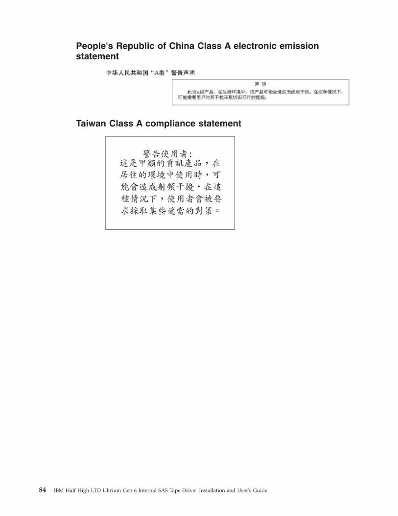
People's Republic of China Class A electronic emissionstatement
Taiwan Class A compliance statement
84 IBM Half High LTO Ultrium Gen 6 Internal SAS Tape Drive: Installation and User's Guide

Glossary
This glossary defines the special terms,abbreviations, and acronyms that are used in thispublication. If you do not find the term you arelooking for, refer to the index or to the Dictionaryof Computing, 1994.
Numbers
2:1 compressionThe relationship between the quantity ofdata that can be stored with compressionas compared to the quantity of data thatcan be stored without compression. In 2:1compression, twice as much data can bestored with compression as can be storedwithout compression.
A
A Ampere.
ac Alternating current.
access methodA technique for moving data betweenmain storage and input or output devices.
adapter cardA circuit board that adds function to acomputer.
adj Adjustment.
AIX Advanced Interactive Executive. IBM’simplementation of the UNIX operatingsystem. The RS/6000 system, amongothers, uses AIX as it's operating system.
alphanumericPertaining to a character set that containsletters, numerals, and usually othercharacters, such as punctuation marks.
alter To change.
ambient temperatureThe temperature of air or other media ina designated area, particularly the areasurrounding equipment.
ampere (A)A unit of measure for electric current thatis equivalent to a flow of one coulombper second, or to the current produced byone volt applied across a resistance of oneohm.
ANSI American National Standards Institute.
archiveTo collect and store files in a designatedplace.
ASCII American National Standard Code forInformation Interchange. A 7 bit codedcharacter set (8 bits including paritycheck) that consists of control charactersand graphic characters.
assigning a deviceThe establishing of the relationship of adevice to a running task, process, job, orprogram.
assignmentThe naming of a specific device toperform a function.
asynchronousPertaining to two or more processes thatdo not depend upon the occurrence ofspecific events such as common timingsignals.
attention (notice)A word for calling attention to thepossibility of danger to a program, device,or system, or to data. Contrast withcaution and danger.
ATTN Attention.
B
backupTo make additional copies of documentsor software for safekeeping.
bar codeA code representing characters by sets ofparallel bars of varying thickness andseparation which are read optically bytransverse scanning.
bar code labelPaper bearing a bar code and having anadhesive backing. The bar code labelmust be affixed to a tape cartridge toenable the library to identify the cartridgeand its volume serial number.
bar code readerA laser device specialized for scanningand reading bar codes and converting
© Copyright IBM Corp. 2013 85

them into either the ASCII or EBCDICdigital character code.
bezel Decorative and safety cover.
bicoloredHaving two colors.
bit Either of the digits 0 or 1 when used inthe binary numbering system.
BM or bill of materialsA list of specific types and amounts ofdirect materials expected to be used toproduce a given job or quantity of output.
browserA client program that initiates requests toa Web server and displays theinformation that the server returns.
bufferA routine or storage used to compensatefor a difference in rate of flow of data ortime of occurrence of events, whentransferring data from one device toanother.
bus A facility for transferring data betweenseveral devices located between two endpoints, only one device being able totransmit at a given moment.
byte A string consisting of a certain number ofbits (usually 8) that are treated as a unitand represent a character. A fundamentaldata unit.
C
capacityThe amount of data that can be containedon storage media and expressed in bytesof data.
cartridge manual rewind toolA device that can be fitted into the reel ofa cartridge and used to rewind tape intoor out of the cartridge.
cartridge storage slotIndividual slot located within a magazinethat is used to house tape cartridges.
caution (notice)A word to call attention to possiblepersonal harm to people. Contrast withattention and danger.
CE Customer engineer; field engineer; servicerepresentative.
centimeter (cm)One one-hundredth of a meter (0.01 m).Approximately 0.39 inch.
channel commandAn instruction that directs a data channel,control unit, or device to perform anoperation or set of operations.
char Character.
CHK Check.
cleaning cartridgeA tape cartridge that is used to clean theheads of a tape drive. Contrast with datacartridge.
commandA control signal that initiates an action orthe start of a sequence of actions.
compact disc (CD)A disc, usually 4.75 inches in diameter,from which data is read optically bymeans of a laser.
compressionThe process of eliminating gaps, emptyfields, redundancies, and unnecessarydata to shorten the length of records orblocks.
concurrentRefers to diagnostic procedures that canbe run on one control unit while the restof the subsystem remains available forcustomer applications.
contingent connectionA connection between a channel path anda drive caused when a unit check occursduring an I/O operation.
controllerA device that provides the interfacebetween a system and one or more tapedrives.
CP Circuit protector.
ctrl Control.
CU Control unit.
D
danger (notice)A word to call attention to possible lethalharm to people. Contrast with attentionand caution.
86 IBM Half High LTO Ultrium Gen 6 Internal SAS Tape Drive: Installation and User's Guide

data Any representations such as characters oranalog quantities to which meaning is ormight be assigned.
data bufferThe storage buffer in the control unit.This buffer is used to increase the datatransfer rate between the control unit andthe channel.
data cartridgeA tape cartridge dedicated to storing data.Contrast with cleaning cartridge.
data checkA synchronous or asynchronousindication of a condition caused byinvalid data or incorrect positioning ofdata.
dc Direct current.
degaussTo make a magnetic tape nonmagnetic bymeans of electrical coils carrying currentsthat neutralize the magnetism of the tape.
degausserA device that makes magnetic tapenonmagnetic.
degradationA decrease in quality of output orthroughput or an increase in machineerror rate.
degradedDecreased in quality of output orthroughput or increased machine errorrate.
deserializeTo change from serial-by-bit toparallel-by-byte.
detentedA part being held in position with a catchor lever.
device Any hardware component or peripheral,such as a tape drive or tape library, thatcan receive and send data.
device driverA file that contains the code needed touse an attached device.
DIAGDiagnostic section of maintenanceinformation manual.
differentialSee High Voltage Differential (HVD).
direct access storageA storage device in which the access timeis independent of the location of the data.
DNS Directory Name System. This allows thelibrary to recognize text-based addressesinstead of numeric IP addresses.
downloadTo transfer programs or data from acomputer to a connected device, typicallya personal computer.
To transfer data from a computer to aconnected device, such as a workstationor microcomputer.
DRAMDynamic random-access memory.
drive, magnetic tapeA mechanism for moving magnetic tapeand controlling its movement.
DRV Drive.
DSE Data security erase.
DSP Digital signal processor.
E
EBCDICExtended binary-coded decimalinterchange code.
EC Edge connector. Engineering change.
ECC Error correction code.
EEPROMElectrically erasable programmableread-only memory.
EIA Electronics Industries Association.
EIA unitA unit of measure, established by theElectronic Industries Association, equal to44.45 millimeters (1.75 inches).
eject To remove or force out from within.
electronic mailCorrespondence in the form of messagestransmitted between user terminals over acomputer network.
e-mail See electronic mail.
EPO Emergency power off.
EPROMErasable programmable read onlymemory.
Glossary 87
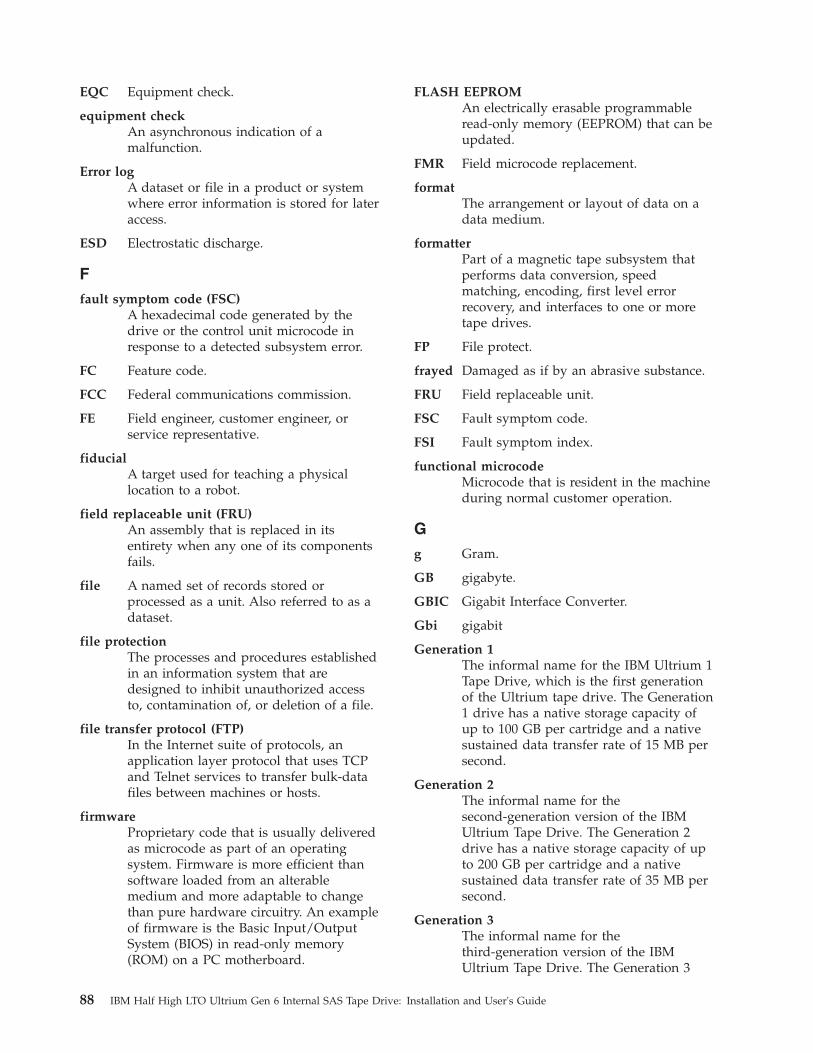
EQC Equipment check.
equipment checkAn asynchronous indication of amalfunction.
Error logA dataset or file in a product or systemwhere error information is stored for lateraccess.
ESD Electrostatic discharge.
F
fault symptom code (FSC)A hexadecimal code generated by thedrive or the control unit microcode inresponse to a detected subsystem error.
FC Feature code.
FCC Federal communications commission.
FE Field engineer, customer engineer, orservice representative.
fiducialA target used for teaching a physicallocation to a robot.
field replaceable unit (FRU)An assembly that is replaced in itsentirety when any one of its componentsfails.
file A named set of records stored orprocessed as a unit. Also referred to as adataset.
file protectionThe processes and procedures establishedin an information system that aredesigned to inhibit unauthorized accessto, contamination of, or deletion of a file.
file transfer protocol (FTP)In the Internet suite of protocols, anapplication layer protocol that uses TCPand Telnet services to transfer bulk-datafiles between machines or hosts.
firmwareProprietary code that is usually deliveredas microcode as part of an operatingsystem. Firmware is more efficient thansoftware loaded from an alterablemedium and more adaptable to changethan pure hardware circuitry. An exampleof firmware is the Basic Input/OutputSystem (BIOS) in read-only memory(ROM) on a PC motherboard.
FLASH EEPROMAn electrically erasable programmableread-only memory (EEPROM) that can beupdated.
FMR Field microcode replacement.
formatThe arrangement or layout of data on adata medium.
formatterPart of a magnetic tape subsystem thatperforms data conversion, speedmatching, encoding, first level errorrecovery, and interfaces to one or moretape drives.
FP File protect.
frayed Damaged as if by an abrasive substance.
FRU Field replaceable unit.
FSC Fault symptom code.
FSI Fault symptom index.
functional microcodeMicrocode that is resident in the machineduring normal customer operation.
G
g Gram.
GB gigabyte.
GBIC Gigabit Interface Converter.
Gbi gigabit
Generation 1The informal name for the IBM Ultrium 1Tape Drive, which is the first generationof the Ultrium tape drive. The Generation1 drive has a native storage capacity ofup to 100 GB per cartridge and a nativesustained data transfer rate of 15 MB persecond.
Generation 2The informal name for thesecond-generation version of the IBMUltrium Tape Drive. The Generation 2drive has a native storage capacity of upto 200 GB per cartridge and a nativesustained data transfer rate of 35 MB persecond.
Generation 3The informal name for thethird-generation version of the IBMUltrium Tape Drive. The Generation 3
88 IBM Half High LTO Ultrium Gen 6 Internal SAS Tape Drive: Installation and User's Guide

drive has a native storage capacity of upto 400 GB per cartridge and a nativesustained data transfer rate of 135 MB persecond.
Generation 4The informal name for thefourth-generation version of the IBMUltrium Tape Drive. The Generation 4drive has a native storage capacity of upto 800 GB per cartridge and a nativesustained data transfer rate of 135 MB persecond.
Generation 5The informal name for the fifth-generationversion of the IBM Ultrium Tape Drive.The Generation 5 drive has a nativestorage capacity of up to 1500 GB percartridge and a native sustained datatransfer rate of 140 MB per second.
Generation 6The informal name for thesixth-generation version of the IBMUltrium Tape Drive. The Generation 6drive has a native storage capacity of upto 2500 GB per cartridge and a nativesustained data transfer rate of 160 MB persecond.
gigabit (Gbit)1 000 000 000 bits.
gigabyte (GB)1 000 000 000 bytes.
Gigabit Interface Converter (GBIC)Converts copper interface to opticinterface.
gnd Ground.
H
hertz (Hz)Unit of frequency. One hertz equals onecycle per second.
hex Hexadecimal.
High Voltage Differential (HVD)A logic signaling system that enables datacommunication between a supported hostand the library. HVD signaling uses apaired plus and minus signal level toreduce the effects of noise on the SCSIbus. Any noise injected into the signal ispresent in both a plus and minus state,and is thereby canceled. Synonymouswith differential.
HVD SCSI Bus High Voltage Differential
Hz Hertz (cycles per second).
I
IBM Ultrium Tape DriveLocated within the library, a data-storagedevice that controls the movement of themagnetic tape in an IBM LTO UltriumTape Cartridge. The drive houses themechanism (drive head) that reads andwrites data to the tape.
ID Identifier.
identifier (ID)(1) In programming languages, a lexicalunit that names a language object; forexample, the names of variables, arrays,records, labels, or procedures. Anidentifier usually consists of a letteroptionally followed by letters, digits, orother characters. (2) One or morecharacters used to identify or name dataelement and possibly to indicate certainproperties of that data element. (3) Asequence of bits or characters thatidentifies a program, device, or system toanother program, device, or system.
IML Initial microprogram load.
initial microprogram load (IML)The action of loading a microprogramfrom an external storage to writablecontrol storage.
initiatorThe component that executes a command.The initiator can be the host system or thetape control unit.
INST Installation.
interfaceA shared boundary. An interface might bea hardware component to link twodevices or it might be a portion of storageor registers accessed by two or morecomputer programs.
interposerThe part used to convert a 68-pinconnector to a 50-pin D-shell connector.
intervention requiredManual action is needed.
INTROIntroduction.
Glossary 89
I/O Input/output.
IOP Input/output processor.
IPL Initial program load.
ITST Idle-time self-test.
K
kilogram (kg)One thousand grams (approximately 2.2pounds).
km kilometer. 1000 Meters, Approximately5/8 mile.
L
LAN Local area network. A computer networkwithin a limited area.
LCD See liquid crystal display.
LDAP Lightweight Directory Access Protocol.This allows the library to use login andpassword information stored on a serverto grant access to the library functionality.
LED Light-emitting diode.
Linear Tape File System (LTFS)A file system that works in conjunctionwith LTO Generation tape technology toaccess data stored on an IBM tapecartridge.
Linear Tape-Open (LTO)A type of tape storage technologydeveloped by the IBM Corporation,Hewlett-Packard, and Certance. LTOtechnology is an “open format”technology, which means that its userswill have multiple sources of product andmedia. The “open” nature of LTOtechnology enables compatibility betweendifferent vendors' offerings by ensuringthat vendors comply with verificationstandards. The LTO technology isimplemented in two formats: the Accelisformat focuses on fast access; the Ultriumformat focuses on high capacity. TheUltrium format is the preferred formatwhen capacity (rather than fast access) isthe key storage consideration. An Ultriumcartridge has a compressed data capacityof up to 800 GB (2:1 compression) and anative data capacity of up to 400 GB.
liquid crystal display (LCD)A low-power display technology used incomputers and other I/O devices.
loadableHaving the ability to be loaded.
LTO cartridge memory (LTO-CM)Within each LTO Ultrium data cartridge,an embedded electronics and interfacemodule that can store and retrieve acartridge's historical usage and otherinformation.
LVD SCSI Bus Low Voltage Differential
M
m Meter. In the Metric System, the basic unitof length; equal to approximately 39.37inches.
magnetic tapeA tape with a magnetical surface layer onwhich data can be stored by magneticrecording.
MAP Maintenance analysis procedure.
mask A pattern of characters that controls theretention or elimination of portions ofanother pattern of characters. To use apattern of characters to control theretention or elimination of portions ofanother pattern of characters.
master fileA file used as an authority in a given joband that is relatively permanent, eventhough its contents may change.Synonymous with main file.
MB Mega Byte (usually expressed as data ratein MB/s or MB/second).
media capacityThe amount of data that can be containedon a storage medium, expressed in bytesof data.
media-type identifierPertaining to the bar code on the bar codelabel of the IBM Ultrium Tape Cartridge,a 2-character code, L1, that representsinformation about the cartridge. Lidentifies the cartridge as one that can beread by devices which incorporate LTOtechnology; 1 indicates that it is the firstgeneration of its type.
mega One million of.
meter In the Metric System, the basic unit oflength; equal to approximately 39.37inches.
90 IBM Half High LTO Ultrium Gen 6 Internal SAS Tape Drive: Installation and User's Guide

micro One millionth of.
microcode(1) One or more micro instructions. (2) Acode, representing the instructions of aninstruction set, implemented in a part ofstorage that is not program-addressable.(3) To design, write, and test one or moremicro instructions. (4) See alsomicroprogram.
microdiagnostic routineA program that runs under the control ofa supervisor, usually to identify fieldreplaceable units.
microdiagnostic utilityA program that is run by the customerengineer to test the machine.
microinstructionA basic or elementary machineinstruction.
microprogramA group of microinstructions that whenexecuted performs a preplanned function.
The term microprogram represents adynamic arrangement or selection of oneor more groups of microinstructions forexecution to perform a particularfunction. The term microcode representsmicroinstructions used in a product as analternative to hard-wired circuitry toimplement certain functions of aprocessor or other system component.
MIM Media information message.
mm Millimeter.
modifierThat which changes the meaning.
mount a deviceTo assign an I/O device with a request tothe operator.
MP Microprocessor.
ms Millisecond.
MSG Message.
multipathPertaining to using more than one path.
N
N/A Not applicable.
node In a network, a point at which one ormore functional units connect channels ordata circuits.
NTP Network Time Protocol. This allows thelibrary to set its internal date and timebased on the date and time of a sever.
NVS Nonvolatile storage. A storage devicewhose contents are not lost when poweris cut off.
O
oerstedThe unit of magnetic field strength in theunrationalized centimeter-gram-second(cgs) electromagnetic system. The oerstedis the magnetic field strength in theinterior of an elongated, uniformlywound solenoid that is excited with alinear current density in its winding ofone abampere per 4π centimeters of axiallength.
offlinePertaining to the operation of a functionalunit without the continual control of acomputer. Contrast with online.
online Pertaining to the operation of a functionalunit that is under the continual control ofa computer. Contrast with offline.
OPER Operation.
ov Over voltage.
overrunLoss of data because a receiving device isunable to accept data at the rate it istransmitted.
overtighteningTo tighten too much.
P
parameterA variable that is given a constant valuefor a specified application and that maydenote the application.
p bit Parity bit.
PC Parity check.
PCC Power control compartment.
PDF Portable Document Format.
PE Parity error. Product engineer.
pick Pertaining to the library, to remove, by
Glossary 91

means of a robotic device, a tape cartridgefrom a storage slot or drive.
picker A robotic mechanism located inside thelibrary that moves cartridges between thecartridge storage slots and the drive.
PM Preventive maintenance.
POR Power-on reset.
port A physical connection for communicationbetween the 3590 and the host processor.The 3590 has two SCSI ports.
Portable Document Format (PDF)A standard specified by Adobe Systems,Incorporated, for the electronicdistribution of documents. PDF files arecompact, can be distributed globally (viae-mail, the Web, intranets, or CD-ROM),and can be viewed with the AcrobatReader, which is software from AdobeSystems that can be downloaded at nocost from the Adobe Systems home page.
PROMProgrammable read only memory.
PS Power supply.
PWR Power.
R
rack A unit that houses the components of astorage subsystem, such as the library.
rackmount kitA packaged collection of articles used toinstall the rack mounted version of thelibrary.
RAM Random access memory.
Random access memoryA storage device into which data isentered and from which data is retrievedin a nonsequential manner.
RAS Reliability, availability, and serviceability.
record A collection of related data or words,treated as a unit.
recording densityThe number of bits in a single linear trackmeasured per unit of length of therecording medium.
recoverable errorAn error condition that allows continuedexecution of a program.
ref Reference.
reg Register.
reinventoryTo inventory again.
retensionThe process or function of tightening thetape onto the cartridge, if it is sensed thatthe tape has a loose wrap on thecartridge.
robot Picker.
roboticsPicker assembly.
RPQ Request for price quotation.
R/W Read/write.
S
s Seconds of time.
SAC Service Action Code. Code developed toindicate possible FRU or FRU's to replaceto repair the hardware.
SAS Serial attached SCSI interface.
scratch cartridgeA data cartridge that contains no usefuldata, but can be written to with new data.
SCSI Small computer system interface.
segmentA part.
sel Select.
serializeTo change from parallel-by-byte toserial-by-bit.
serializerA device that converts a spacedistribution of simultaneous statesrepresenting data into a correspondingtime sequence of states.
servo, servosAn adjective for use in qualifying somepart or aspect of a servomechanism.
servomechanismA feedback control system in which atleast one of the system signals representsmechanical motion.
Small Computer Systems Interface (SCSI)A standard used by computermanufacturers for attaching peripheral
92 IBM Half High LTO Ultrium Gen 6 Internal SAS Tape Drive: Installation and User's Guide

devices (such as tape drives, hard disks,CD-ROM players, printers, and scanners)to computers (servers). Pronounced“scuzzy”. Variations of the SCSI interfaceprovide for faster data transmission ratesthan standard serial and parallel ports (upto 160 megabytes per second). Thevariations include:v Fast/Wide SCSI: Uses a 16-bit bus, and
supports data rates of up to 20 MBps.v SCSI-1: Uses an 8-bit bus, and supports
data rates of 4 MBps.v SCSI-2: Same as SCSI-1, but uses a
50-pin connector instead of a 25-pinconnector, and supports multipledevices.
v Ultra SCSI: Uses an 8- or 16-bit bus,and supports data rates of 20 or 40MBps.
v Ultra2 SCSI: Uses an 8- or 16-bit busand supports data rates of 40 or 80MBps.
v Ultra3 SCSI: Uses a 16-bit bus andsupports data rates of 80 or 160 MBps.
v Ultra160 SCSI: Uses a 16-bit bus andsupports data rates of 80 or 160 MBps.
SNS Sense.
special featureA feature that can be ordered to enhancethe capability, storage capacity, orperformance of a product, but is notessential for its basic work.
SR Service representative, see also CE.
SRAMStatic random access memory.
SS Status store.
ST Store.
standard featureThe significant design elements of aproduct that are included as part of thefundamental product.
STARTStart maintenance.
subsystemA secondary or subordinate system,usually capable of operatingindependently of, or asynchronously with,a controlling system.
SUPP Support.
sync Synchronous, synchronize. Occurring witha regular or predictable time relationship.
T
tachometer, tachA device that emits pulses that are usedto measure/check speed or distance.
tape cartridgeA container holding magnetic tape thatcan be processed without separating itfrom the container.
tape voidAn area in the tape in which no signalcan be detected.
TCP/IPTransmission Control Protocol/InternetProtocol.
TCU Tape control unit.
TH Thermal.
thread/load operationA procedure that places tape along thetape path.
TM Tapemark.
U
UART Universal asynchronousreceiver/transmitter.
unloadPrepare the tape cartridge for removalfrom the drive.
utilitiesUtility programs.
utility programsA computer program in general supportof the processes of a computer; forinstance, a diagnostic program.
uv Under voltage.
V
VOLSERVolume serial number.
volumeA certain portion of data, together with itsdata carrier, that can be handledconveniently as a unit.
VPD Vital product data. The informationcontained within the tape drive thatrequires nonvolatile storage used by
Glossary 93

functional areas of the drive, andinformation required for manufacturing,RAS, and engineering.
W
word A character string that is convenient forsome purpose to consider as an entity.
Write Write command.
WT world trade.
X
XR External register.
XRA External register address register.
94 IBM Half High LTO Ultrium Gen 6 Internal SAS Tape Drive: Installation and User's Guide

Index
Aaccessible documentation 80acclimate drive 11adjust data rate 4AME
See Application Managed Encryption(AME)
Application Managed Encryption(AME) 5
assistance, getting 57attaching tape drive to server 6Australia Class A statement 81
Bbutton, unload 21
CCanada Class A electronic emission
statement 81capacity scaling 5cartridge 43
capacity scaling 5, 44cleaning 47compatibility 3, 47data 44disposing of 51environmental specifications 50handling 47, 48inserting 22inspecting 48inspecting for damage 53mid-tape recovery 23packaging 49problem 69problems 69removing 23repairing 69shipping specifications 50specifications 47testing 35types 44WORM 45
Cartridgecapacity scaling 45memory chip 44Write-Protect Switch 45
cartridge, environment 47channel calibration 5China Class A electronic emission
statement 84Class A electronic emission notice 81cleaning the drive 24Configure drive
to hub 14to server 14to switch 14
Connecting SAS interface 14
contamination, particulate andgaseous 79
creating a personalized support webpage 58
CRU part numbers 1custom support web page 58customize each data channel 5
Ddescription of drive 1device drivers
supported 6Device drivers
installing 13Diagnostic, tape drive 40diagnostics 32
clear error code log 34copying drive dump to tape 31disabling post error reporting 40display error code log 34enabling post error reporting 39fast read/write test 38forcing a drive dump 30load/unload test 39RS-422 wrap test 33selecting function 25tape drive 28test cartridge 35test head 37write performance test 36
Diagnostics 40running 13
displaySCD dot 17single-character 17
documentationformat 80using 58
driveavoiding damage 9cleaning 47cleaning cartridge 47description 1features 1front view 2performance 3rear view 2
drive cleaning 24drive dump
copying to tape 31forcing 30
drive headcleaning 23
drive monitoring 6drive servicing 6DSA, sending data to IBM 58
Eelectrical equipment, servicing xielectronic emission Class A notice 81encryption 5error code log
clear 34display 34
error codes 63errors
WORM media 45Ethernet (RJ45) 40ethernet port 6European Union EMC Directive
conformance statement 81
Ffast read/write test 38FCC Class A notice 81feature switches 11features of drive 1Fibre Channel interface
internal cable connection 13firmware
inhibiting down-leveling 5updating 14
using FMR tape 14using ITDT tool 14
FMR tapecreate 30unmake 33update firmware 29
front panel features 2Function code 0: Exit Maintenance
mode 28Function code 1: Run drive
diagnostics 28Function code 2: Update drive firmware
from FMR tape 29Function code 3: Create FMR tape 30Function code 4: Force a drive dump 30Function code 5: Copy drive dump 31Function code 6: Run host interface wrap
test 32Function code 7: Run RS-422 wrap
test 33Function code 8: Unmake FMR tape 33Function code 9: Display error code
log 34Function code A: Clear error code
log 34Function code C: Insert cartridge into
tape drive 35Function code E: Test cartridge &
media 35Function code F: Write performance
test 36Function code H: Test head 37Function code J: Fast read/write test 38Function code L: Load/unload test 39
© Copyright IBM Corp. 2013 95

Function code P: Enable post errorreporting 39
Function code U: Disable post errorreporting 40
Ggaseous contamination 79Germany Class A statement 82glossary 85guidelines
servicing electrical equipment xitrained service technicians x
Hhardware service and support telephone
numbers 59help
from the World Wide Web 58from World Wide Web 58sending diagnostic data to IBM 58sources of 57
host interfacephysical characteristics 5
host wrap test 32
IIBM Taiwan product service 59important notices 78information center 58insert cartridge 35inspecting for unsafe conditions xInstallation 9installation guidelines 9installing 9
tape drive 10
JJapan Class A electronic emission
statement 83Japan Electronics and Information
Technology Industries Associationstatement 83
JEITA statement 83
KKorea Class A electronic emission
statement 83
Lleader pin
reattaching 71repositioning 69
Linear Tape File System 6load/unload est 39LTFS 6
Mmaintenance
create FMR tape 30update firmware with FMR tape 29
maintenance functionselecting function 25unmaking an FMR tape 33
Maintenance mode 17entering 27exiting 27, 28
Maintenance, tape drive 40media 43
acclimating 48capacity scaling 5cartridge compatibility 3disposing of 51environmental conditions 48environmental specifications 50handling 48inserting 22inspecting 48inspecting for damage 53mid-tape recovery 23packaging 49removing 23resolving problems 55shipping specifications 50training 48
message codes 63Mounting
enclosure 12server 12
My Support 15
NNew Zealand Class A statement 81notes, important 78notices 77
electronic emission 81FCC, Class A 81
Ooperating instructions 17operating modes 17Operating systems supported 6operating systems, supported 6Operation mode 17Option part numbers 1
PPart numbers
CRU 1Option 1
particulate contamination 79People's Republic of China Class A
electronic emission statement 84performance 3post error reporting
disabling 40enabling 39
powerbutton 17
Powerconnect to drive 12test to drive 12
problem determination 53problems reported by server
resolving 55product service, IBM Taiwan 59
Rread and write capability 47rear panel features 2repair identification tag (RID) 56replaceable components 56replacement procedure 56requirements for attaching tape drive to
server 6RS-422 wrap test 33Russia Class A electronic emission
statement 83
Ssafety ix, 9safety statements ix, xiiSAS Host connections
checking 54SAS interface 5
external 14internal cable connection 13
SCSI interfaceexternal server connection 14internal cable connection 13
sending diagnostic data to IBM 58server connection
external SCSI 14Servers supported 6servers, supported 6service and support
before you call 57hardware 59software 59
servicing electrical equipment xishipment, verifying 10software service and support telephone
numbers 59specifications
cartridges 47speed matching 4status light 18status, tape drive 24support web page, custom 58supported device drivers 6supported SAN components 6supported servers and operating
systems 6switches, feature 11
TTaiwan Class A electronic emission
statement 84tape drive
installation 10tape drive status 24tape drive status, web page 24
96 IBM Half High LTO Ultrium Gen 6 Internal SAS Tape Drive: Installation and User's Guide

TapeAlert flags 61telecommunication regulatory
statement 80telephone numbers 59test drive head 37trademarks 77trained service technicians, guidelines xtraining
media handling 48turn off
enclosure or server 11
UUnited States FCC Class A notice 81unload button 21unpacking shipment 10Unpacking shipment 10unsafe conditions, inspecting for xupdating firmware 14
using FMR tape 14using Host Interface 14using ITDT tool 14
VVerifying Host Interface
Communications 54
WWORM
requirements 45WORM (Write Once, Read Many) 45WORM media errors 45Write Once, Read Many (see WORM) 45write performance test 36Write-Protect Switch
setting 45
Index 97

98 IBM Half High LTO Ultrium Gen 6 Internal SAS Tape Drive: Installation and User's Guide


����
Part Number: 00Y8026
Printed in USA
(1P) P/N: 00Y8026