The IBM LTO Ultrium Tape Libraries Guide -...
276
ibm.com/redbooks The IBM LTO Ultrium Tape Libraries Guide Charlotte Brooks Carsten Krax Tony Rynan Josef Weingand Understand Linear Tape-Open technology and its unique architecture Learn about the IBM Ultrium drives and libraries Updated for Ultrium LTO 2 products
Transcript of The IBM LTO Ultrium Tape Libraries Guide -...

ibm.com/redbooks
The IBM LTO Ultrium Tape Libraries Guide
Charlotte BrooksCarsten Krax
Tony RynanJosef Weingand
Understand Linear Tape-Open technology and its unique architecture
Learn about the IBM Ultrium drives and libraries
Updated for Ultrium LTO 2 products
Front cover


The IBM LTO Ultrium Tape Libraries Guide
June 2003
International Technical Support Organization
SG24-5946-01
© Copyright International Business Machines Corporation 2000, 2003. All rights reserved.Note to U.S. Government Users Restricted Rights: Use, duplication or disclosure restricted by GSA ADPSchedule Contract with IBM Corp.
Second Edition (June 2003)
This edition applies to the IBM TotalStorage Ultrium Tape Drive 3580, IBM TotalStorage Ultrium Tape Autoloader 3581, IBM TotalStorage Ultrium Tape Library 3582, IBM TotalStorage Ultrium Scalable Tape Library 3583, and IBM TotalStorage UltraScalable Tape Library 3584.
Note: Before using this information and the product it supports, read the information in “Notices” on page xvii.
Contents
Figures . . . . . . . . . . . . . . . . . . . . . . . . . . . . . . . . . . . . . . . . . . . . . . . . . . . . . . . xi
Tables . . . . . . . . . . . . . . . . . . . . . . . . . . . . . . . . . . . . . . . . . . . . . . . . . . . . . . . xv
Notices . . . . . . . . . . . . . . . . . . . . . . . . . . . . . . . . . . . . . . . . . . . . . . . . . . . . . xviiTrademarks . . . . . . . . . . . . . . . . . . . . . . . . . . . . . . . . . . . . . . . . . . . . . . . . . . xviii
Preface . . . . . . . . . . . . . . . . . . . . . . . . . . . . . . . . . . . . . . . . . . . . . . . . . . . . . . xixThe team that wrote this redbook. . . . . . . . . . . . . . . . . . . . . . . . . . . . . . . . . . . xixBecome a published author . . . . . . . . . . . . . . . . . . . . . . . . . . . . . . . . . . . . . . . xxiComments welcome. . . . . . . . . . . . . . . . . . . . . . . . . . . . . . . . . . . . . . . . . . . . xxii
Summary of changes . . . . . . . . . . . . . . . . . . . . . . . . . . . . . . . . . . . . . . . . . . xxiiiJune 2003, Second Edition . . . . . . . . . . . . . . . . . . . . . . . . . . . . . . . . . . . . . . xxiii
Chapter 1. Introduction to Linear Tape-Open (LTO) . . . . . . . . . . . . . . . . . . . 11.1 The LTO organization . . . . . . . . . . . . . . . . . . . . . . . . . . . . . . . . . . . . . . . . . 2
1.1.1 Open licensing and manufacture . . . . . . . . . . . . . . . . . . . . . . . . . . . . 31.1.2 License packages . . . . . . . . . . . . . . . . . . . . . . . . . . . . . . . . . . . . . . . . 41.1.3 Compliance verification . . . . . . . . . . . . . . . . . . . . . . . . . . . . . . . . . . . . 5
1.2 LTO standards. . . . . . . . . . . . . . . . . . . . . . . . . . . . . . . . . . . . . . . . . . . . . . . 51.2.1 Ultrium tape formats . . . . . . . . . . . . . . . . . . . . . . . . . . . . . . . . . . . . . . 51.2.2 LTO core technology. . . . . . . . . . . . . . . . . . . . . . . . . . . . . . . . . . . . . . 6
Chapter 2. LTO technology . . . . . . . . . . . . . . . . . . . . . . . . . . . . . . . . . . . . . . . 92.1 Interleaved recording. . . . . . . . . . . . . . . . . . . . . . . . . . . . . . . . . . . . . . . . . 10
2.1.1 Servo tracks . . . . . . . . . . . . . . . . . . . . . . . . . . . . . . . . . . . . . . . . . . . 102.1.2 Data tracks . . . . . . . . . . . . . . . . . . . . . . . . . . . . . . . . . . . . . . . . . . . . 132.1.3 Linear density . . . . . . . . . . . . . . . . . . . . . . . . . . . . . . . . . . . . . . . . . . 16
2.2 Data compression . . . . . . . . . . . . . . . . . . . . . . . . . . . . . . . . . . . . . . . . . . . 162.3 Tape cartridge . . . . . . . . . . . . . . . . . . . . . . . . . . . . . . . . . . . . . . . . . . . . . . 18
2.3.1 Metal particle medium . . . . . . . . . . . . . . . . . . . . . . . . . . . . . . . . . . . . 202.3.2 Cartridge memory (LTO-CM) . . . . . . . . . . . . . . . . . . . . . . . . . . . . . . 202.3.3 Barcode label . . . . . . . . . . . . . . . . . . . . . . . . . . . . . . . . . . . . . . . . . . 222.3.4 Volume label format . . . . . . . . . . . . . . . . . . . . . . . . . . . . . . . . . . . . . 232.3.5 Write protect switch. . . . . . . . . . . . . . . . . . . . . . . . . . . . . . . . . . . . . . 242.3.6 Cleaning the cartridge . . . . . . . . . . . . . . . . . . . . . . . . . . . . . . . . . . . . 242.3.7 Cartridge life . . . . . . . . . . . . . . . . . . . . . . . . . . . . . . . . . . . . . . . . . . . 242.3.8 Cleaning cartridge . . . . . . . . . . . . . . . . . . . . . . . . . . . . . . . . . . . . . . . 25
© Copyright IBM Corp. 2000, 2003. All rights reserved. iii

2.3.9 Cartridge handling. . . . . . . . . . . . . . . . . . . . . . . . . . . . . . . . . . . . . . . 252.4 IBM LTO Ultrium common subassembly. . . . . . . . . . . . . . . . . . . . . . . . . . 28
2.4.1 Drive head. . . . . . . . . . . . . . . . . . . . . . . . . . . . . . . . . . . . . . . . . . . . . 292.4.2 Data compression . . . . . . . . . . . . . . . . . . . . . . . . . . . . . . . . . . . . . . . 302.4.3 Interfaces . . . . . . . . . . . . . . . . . . . . . . . . . . . . . . . . . . . . . . . . . . . . . 312.4.4 Performance . . . . . . . . . . . . . . . . . . . . . . . . . . . . . . . . . . . . . . . . . . . 352.4.5 Partial Response Maximum Likelihood (PRML) . . . . . . . . . . . . . . . . 362.4.6 IBM Ultrium 2: additional improvements . . . . . . . . . . . . . . . . . . . . . . 372.4.7 IBM Ultrium 1 and 2 compatibility . . . . . . . . . . . . . . . . . . . . . . . . . . . 392.4.8 Operating the Ultrium drive . . . . . . . . . . . . . . . . . . . . . . . . . . . . . . . . 392.4.9 Reliability . . . . . . . . . . . . . . . . . . . . . . . . . . . . . . . . . . . . . . . . . . . . . . 412.4.10 Cleaning the drive . . . . . . . . . . . . . . . . . . . . . . . . . . . . . . . . . . . . . . 43
2.5 The IBM LTO Ultrium family of tapes and libraries . . . . . . . . . . . . . . . . . . 442.6 Multi-path architecture. . . . . . . . . . . . . . . . . . . . . . . . . . . . . . . . . . . . . . . . 46
Chapter 3. Tape storage market direction. . . . . . . . . . . . . . . . . . . . . . . . . . 493.1 Current tape products and technologies . . . . . . . . . . . . . . . . . . . . . . . . . . 50
3.1.1 Helical versus longitudinal. . . . . . . . . . . . . . . . . . . . . . . . . . . . . . . . . 503.1.2 Tape reels (1/2-inch) . . . . . . . . . . . . . . . . . . . . . . . . . . . . . . . . . . . . . 523.1.3 QIC . . . . . . . . . . . . . . . . . . . . . . . . . . . . . . . . . . . . . . . . . . . . . . . . . . 523.1.4 Digital Data Standard (4 mm) . . . . . . . . . . . . . . . . . . . . . . . . . . . . . . 543.1.5 The 8 mm format . . . . . . . . . . . . . . . . . . . . . . . . . . . . . . . . . . . . . . . . 563.1.6 Digital Linear Tape (DLT) . . . . . . . . . . . . . . . . . . . . . . . . . . . . . . . . . 583.1.7 SuperDLT (SDLT) . . . . . . . . . . . . . . . . . . . . . . . . . . . . . . . . . . . . . . . 623.1.8 IBM 3480. . . . . . . . . . . . . . . . . . . . . . . . . . . . . . . . . . . . . . . . . . . . . . 633.1.9 IBM 3490. . . . . . . . . . . . . . . . . . . . . . . . . . . . . . . . . . . . . . . . . . . . . . 633.1.10 IBM Magstar 3590. . . . . . . . . . . . . . . . . . . . . . . . . . . . . . . . . . . . . . 643.1.11 STK 9840 . . . . . . . . . . . . . . . . . . . . . . . . . . . . . . . . . . . . . . . . . . . . 653.1.12 STK 9940 . . . . . . . . . . . . . . . . . . . . . . . . . . . . . . . . . . . . . . . . . . . . 663.1.13 LTO Ultrium. . . . . . . . . . . . . . . . . . . . . . . . . . . . . . . . . . . . . . . . . . . 663.1.14 Libraries . . . . . . . . . . . . . . . . . . . . . . . . . . . . . . . . . . . . . . . . . . . . . 67
3.2 Current SAN technologies. . . . . . . . . . . . . . . . . . . . . . . . . . . . . . . . . . . . . 683.2.1 SAN definition . . . . . . . . . . . . . . . . . . . . . . . . . . . . . . . . . . . . . . . . . . 703.2.2 Fibre Channel architecture . . . . . . . . . . . . . . . . . . . . . . . . . . . . . . . . 703.2.3 Topologies. . . . . . . . . . . . . . . . . . . . . . . . . . . . . . . . . . . . . . . . . . . . . 713.2.4 Tape solutions in a SAN environment . . . . . . . . . . . . . . . . . . . . . . . . 71
Chapter 4. IBM TotalStorage Ultrium Tape Drive 3580 . . . . . . . . . . . . . . . . 794.1 Model description . . . . . . . . . . . . . . . . . . . . . . . . . . . . . . . . . . . . . . . . . . . 804.2 Feature codes . . . . . . . . . . . . . . . . . . . . . . . . . . . . . . . . . . . . . . . . . . . . . . 814.3 SCSI attachment . . . . . . . . . . . . . . . . . . . . . . . . . . . . . . . . . . . . . . . . . . . . 824.4 SCSI cabling . . . . . . . . . . . . . . . . . . . . . . . . . . . . . . . . . . . . . . . . . . . . . . . 82
4.4.1 Cables . . . . . . . . . . . . . . . . . . . . . . . . . . . . . . . . . . . . . . . . . . . . . . . . 82
iv The IBM LTO Ultrium Tape Libraries Guide

4.4.2 Interposers . . . . . . . . . . . . . . . . . . . . . . . . . . . . . . . . . . . . . . . . . . . . 834.4.3 SCSI length limitations . . . . . . . . . . . . . . . . . . . . . . . . . . . . . . . . . . . 83
4.5 Upgrades. . . . . . . . . . . . . . . . . . . . . . . . . . . . . . . . . . . . . . . . . . . . . . . . . . 844.6 Environmental specifications. . . . . . . . . . . . . . . . . . . . . . . . . . . . . . . . . . . 84
4.6.1 Physical dimensions . . . . . . . . . . . . . . . . . . . . . . . . . . . . . . . . . . . . . 844.6.2 Operating environment . . . . . . . . . . . . . . . . . . . . . . . . . . . . . . . . . . . 84
4.7 Host platforms and device drivers . . . . . . . . . . . . . . . . . . . . . . . . . . . . . . . 844.7.1 Device driver installation . . . . . . . . . . . . . . . . . . . . . . . . . . . . . . . . . . 85
4.8 Storage applications . . . . . . . . . . . . . . . . . . . . . . . . . . . . . . . . . . . . . . . . . 864.9 Performance considerations . . . . . . . . . . . . . . . . . . . . . . . . . . . . . . . . . . . 864.10 Media. . . . . . . . . . . . . . . . . . . . . . . . . . . . . . . . . . . . . . . . . . . . . . . . . . . . 874.11 IBM 3580 Ultrium tape drive initial set-up . . . . . . . . . . . . . . . . . . . . . . . . 87
4.11.1 SCSI ID . . . . . . . . . . . . . . . . . . . . . . . . . . . . . . . . . . . . . . . . . . . . . . 874.12 Operator displays and buttons . . . . . . . . . . . . . . . . . . . . . . . . . . . . . . . . 88
4.12.1 Status light . . . . . . . . . . . . . . . . . . . . . . . . . . . . . . . . . . . . . . . . . . . 884.12.2 Message display . . . . . . . . . . . . . . . . . . . . . . . . . . . . . . . . . . . . . . . 894.12.3 The single-character display . . . . . . . . . . . . . . . . . . . . . . . . . . . . . . 894.12.4 Unload push button . . . . . . . . . . . . . . . . . . . . . . . . . . . . . . . . . . . . . 90
4.13 Drive cleaning . . . . . . . . . . . . . . . . . . . . . . . . . . . . . . . . . . . . . . . . . . . . . 904.14 Firmware upgrade . . . . . . . . . . . . . . . . . . . . . . . . . . . . . . . . . . . . . . . . . . 91
Chapter 5. IBM TotalStorage Ultrium Tape Autoloader 3581 . . . . . . . . . . . 935.1 Model description . . . . . . . . . . . . . . . . . . . . . . . . . . . . . . . . . . . . . . . . . . . 95
5.1.1 Feature codes . . . . . . . . . . . . . . . . . . . . . . . . . . . . . . . . . . . . . . . . . . 965.1.2 Access mode. . . . . . . . . . . . . . . . . . . . . . . . . . . . . . . . . . . . . . . . . . . 965.1.3 SCSI devices. . . . . . . . . . . . . . . . . . . . . . . . . . . . . . . . . . . . . . . . . . . 975.1.4 Adding and removing cartridges . . . . . . . . . . . . . . . . . . . . . . . . . . . . 975.1.5 Operation . . . . . . . . . . . . . . . . . . . . . . . . . . . . . . . . . . . . . . . . . . . . . 98
5.2 SCSI attachments . . . . . . . . . . . . . . . . . . . . . . . . . . . . . . . . . . . . . . . . . . . 985.3 SCSI cabling . . . . . . . . . . . . . . . . . . . . . . . . . . . . . . . . . . . . . . . . . . . . . . . 98
5.3.1 Cables . . . . . . . . . . . . . . . . . . . . . . . . . . . . . . . . . . . . . . . . . . . . . . . . 995.3.2 Interposers . . . . . . . . . . . . . . . . . . . . . . . . . . . . . . . . . . . . . . . . . . . . 995.3.3 SCSI length limitations . . . . . . . . . . . . . . . . . . . . . . . . . . . . . . . . . . 100
5.4 Upgrades and optional features . . . . . . . . . . . . . . . . . . . . . . . . . . . . . . . 1005.5 Environmental specifications. . . . . . . . . . . . . . . . . . . . . . . . . . . . . . . . . . 101
5.5.1 Physical dimensions . . . . . . . . . . . . . . . . . . . . . . . . . . . . . . . . . . . . 1015.5.2 Operating environment . . . . . . . . . . . . . . . . . . . . . . . . . . . . . . . . . . 101
5.6 Host platforms and device drivers . . . . . . . . . . . . . . . . . . . . . . . . . . . . . . 1015.6.1 Device driver installation . . . . . . . . . . . . . . . . . . . . . . . . . . . . . . . . . 102
5.7 Storage applications . . . . . . . . . . . . . . . . . . . . . . . . . . . . . . . . . . . . . . . . 1035.8 Performance considerations . . . . . . . . . . . . . . . . . . . . . . . . . . . . . . . . . . 1035.9 Media. . . . . . . . . . . . . . . . . . . . . . . . . . . . . . . . . . . . . . . . . . . . . . . . . . . . 1035.10 IBM 3581 initial setup . . . . . . . . . . . . . . . . . . . . . . . . . . . . . . . . . . . . . . 104
Contents v
5.10.1 SCSI ID . . . . . . . . . . . . . . . . . . . . . . . . . . . . . . . . . . . . . . . . . . . . . 1045.10.2 Element numbers . . . . . . . . . . . . . . . . . . . . . . . . . . . . . . . . . . . . . 1055.10.3 Operator displays and buttons . . . . . . . . . . . . . . . . . . . . . . . . . . . 1055.10.4 Message display . . . . . . . . . . . . . . . . . . . . . . . . . . . . . . . . . . . . . . 1065.10.5 Drive status messages . . . . . . . . . . . . . . . . . . . . . . . . . . . . . . . . . 1075.10.6 Control buttons . . . . . . . . . . . . . . . . . . . . . . . . . . . . . . . . . . . . . . . 1085.10.7 Operating modes. . . . . . . . . . . . . . . . . . . . . . . . . . . . . . . . . . . . . . 110
5.11 Drive cleaning . . . . . . . . . . . . . . . . . . . . . . . . . . . . . . . . . . . . . . . . . . . . 1115.12 Firmware upgrade . . . . . . . . . . . . . . . . . . . . . . . . . . . . . . . . . . . . . . . . . 112
Chapter 6. IBM TotalStorage Ultrium Tape Library 3582 . . . . . . . . . . . . . 1136.1 Model description . . . . . . . . . . . . . . . . . . . . . . . . . . . . . . . . . . . . . . . . . . 114
6.1.1 Tape drives . . . . . . . . . . . . . . . . . . . . . . . . . . . . . . . . . . . . . . . . . . . 1156.1.2 Cartridge storage . . . . . . . . . . . . . . . . . . . . . . . . . . . . . . . . . . . . . . 1156.1.3 Barcode scanner . . . . . . . . . . . . . . . . . . . . . . . . . . . . . . . . . . . . . . . 1176.1.4 I/O station . . . . . . . . . . . . . . . . . . . . . . . . . . . . . . . . . . . . . . . . . . . . 1176.1.5 Robotic system . . . . . . . . . . . . . . . . . . . . . . . . . . . . . . . . . . . . . . . . 1176.1.6 Library control and operation . . . . . . . . . . . . . . . . . . . . . . . . . . . . . 1176.1.7 Operator panel . . . . . . . . . . . . . . . . . . . . . . . . . . . . . . . . . . . . . . . . 1186.1.8 Maintenance . . . . . . . . . . . . . . . . . . . . . . . . . . . . . . . . . . . . . . . . . . 118
6.2 Feature codes . . . . . . . . . . . . . . . . . . . . . . . . . . . . . . . . . . . . . . . . . . . . . 1186.3 Physical attachments . . . . . . . . . . . . . . . . . . . . . . . . . . . . . . . . . . . . . . . 1196.4 SCSI cabling . . . . . . . . . . . . . . . . . . . . . . . . . . . . . . . . . . . . . . . . . . . . . . 120
6.4.1 Cables . . . . . . . . . . . . . . . . . . . . . . . . . . . . . . . . . . . . . . . . . . . . . . . 1206.4.2 Interposers . . . . . . . . . . . . . . . . . . . . . . . . . . . . . . . . . . . . . . . . . . . 1216.4.3 SCSI length limitations . . . . . . . . . . . . . . . . . . . . . . . . . . . . . . . . . . 121
6.5 Environmental specifications. . . . . . . . . . . . . . . . . . . . . . . . . . . . . . . . . . 1216.6 Host platforms and device drivers . . . . . . . . . . . . . . . . . . . . . . . . . . . . . . 121
6.6.1 Device driver installation . . . . . . . . . . . . . . . . . . . . . . . . . . . . . . . . . 1226.7 Storage applications . . . . . . . . . . . . . . . . . . . . . . . . . . . . . . . . . . . . . . . . 1236.8 Media. . . . . . . . . . . . . . . . . . . . . . . . . . . . . . . . . . . . . . . . . . . . . . . . . . . . 1236.9 Installation and performance considerations. . . . . . . . . . . . . . . . . . . . . . 1246.10 IBM 3582 initial set-up. . . . . . . . . . . . . . . . . . . . . . . . . . . . . . . . . . . . . . 124
6.10.1 SCSI ID . . . . . . . . . . . . . . . . . . . . . . . . . . . . . . . . . . . . . . . . . . . . . 1256.10.2 Identifying library location element numbers. . . . . . . . . . . . . . . . . 125
6.11 Operator displays and buttons . . . . . . . . . . . . . . . . . . . . . . . . . . . . . . . 1256.11.1 Operator Panel . . . . . . . . . . . . . . . . . . . . . . . . . . . . . . . . . . . . . . . 126
6.12 Library mode . . . . . . . . . . . . . . . . . . . . . . . . . . . . . . . . . . . . . . . . . . . . . 1286.13 Drive cleaning . . . . . . . . . . . . . . . . . . . . . . . . . . . . . . . . . . . . . . . . . . . . 1286.14 Firmware upgrades . . . . . . . . . . . . . . . . . . . . . . . . . . . . . . . . . . . . . . . . 128
Chapter 7. IBM TotalStorage Ultrium Scalable Tape Library 3583 . . . . . 1297.1 Model description . . . . . . . . . . . . . . . . . . . . . . . . . . . . . . . . . . . . . . . . . . 131
vi The IBM LTO Ultrium Tape Libraries Guide

7.1.1 Tape drives . . . . . . . . . . . . . . . . . . . . . . . . . . . . . . . . . . . . . . . . . . . 1317.1.2 Cartridge storage . . . . . . . . . . . . . . . . . . . . . . . . . . . . . . . . . . . . . . 1327.1.3 Barcode reader . . . . . . . . . . . . . . . . . . . . . . . . . . . . . . . . . . . . . . . . 1327.1.4 I/O station . . . . . . . . . . . . . . . . . . . . . . . . . . . . . . . . . . . . . . . . . . . . 1337.1.5 Robotic system . . . . . . . . . . . . . . . . . . . . . . . . . . . . . . . . . . . . . . . . 1337.1.6 Library control and operation . . . . . . . . . . . . . . . . . . . . . . . . . . . . . 1337.1.7 Operator panel . . . . . . . . . . . . . . . . . . . . . . . . . . . . . . . . . . . . . . . . 1347.1.8 Remote Management Unit . . . . . . . . . . . . . . . . . . . . . . . . . . . . . . . 1347.1.9 Library partitioning. . . . . . . . . . . . . . . . . . . . . . . . . . . . . . . . . . . . . . 1347.1.10 Multiple control paths . . . . . . . . . . . . . . . . . . . . . . . . . . . . . . . . . . 1357.1.11 SAN Data Gateway Module . . . . . . . . . . . . . . . . . . . . . . . . . . . . . 1357.1.12 Maintenance . . . . . . . . . . . . . . . . . . . . . . . . . . . . . . . . . . . . . . . . . 135
7.2 Feature codes . . . . . . . . . . . . . . . . . . . . . . . . . . . . . . . . . . . . . . . . . . . . . 1367.3 Physical attachments . . . . . . . . . . . . . . . . . . . . . . . . . . . . . . . . . . . . . . . 1377.4 Cabling . . . . . . . . . . . . . . . . . . . . . . . . . . . . . . . . . . . . . . . . . . . . . . . . . . 138
7.4.1 Fibre Channel cables . . . . . . . . . . . . . . . . . . . . . . . . . . . . . . . . . . . 1387.4.2 SCSI cables . . . . . . . . . . . . . . . . . . . . . . . . . . . . . . . . . . . . . . . . . . 1397.4.3 Interposers . . . . . . . . . . . . . . . . . . . . . . . . . . . . . . . . . . . . . . . . . . . 1407.4.4 Terminator . . . . . . . . . . . . . . . . . . . . . . . . . . . . . . . . . . . . . . . . . . . . 1407.4.5 Cable length limitations . . . . . . . . . . . . . . . . . . . . . . . . . . . . . . . . . . 140
7.5 Upgrades and optional features . . . . . . . . . . . . . . . . . . . . . . . . . . . . . . . 1417.5.1 Upgrade features . . . . . . . . . . . . . . . . . . . . . . . . . . . . . . . . . . . . . . 1417.5.2 Optional features. . . . . . . . . . . . . . . . . . . . . . . . . . . . . . . . . . . . . . . 142
7.6 Environmental specifications. . . . . . . . . . . . . . . . . . . . . . . . . . . . . . . . . . 1427.7 Host platforms and device drivers . . . . . . . . . . . . . . . . . . . . . . . . . . . . . . 143
7.7.1 Device driver installation . . . . . . . . . . . . . . . . . . . . . . . . . . . . . . . . . 1447.8 Storage applications . . . . . . . . . . . . . . . . . . . . . . . . . . . . . . . . . . . . . . . . 1447.9 Media. . . . . . . . . . . . . . . . . . . . . . . . . . . . . . . . . . . . . . . . . . . . . . . . . . . . 1457.10 Installation and performance considerations. . . . . . . . . . . . . . . . . . . . . 1457.11 IBM 3583 initial set-up. . . . . . . . . . . . . . . . . . . . . . . . . . . . . . . . . . . . . . 146
7.11.1 SCSI ID and LUN assignment. . . . . . . . . . . . . . . . . . . . . . . . . . . . 1467.11.2 Identifying library locations . . . . . . . . . . . . . . . . . . . . . . . . . . . . . . 1477.11.3 Element numbers . . . . . . . . . . . . . . . . . . . . . . . . . . . . . . . . . . . . . 150
7.12 Operator panel and RMU . . . . . . . . . . . . . . . . . . . . . . . . . . . . . . . . . . . 1517.12.1 Operator panel . . . . . . . . . . . . . . . . . . . . . . . . . . . . . . . . . . . . . . . 1517.12.2 RMU with TotalStorage Specialist. . . . . . . . . . . . . . . . . . . . . . . . . 154
7.13 Random access. . . . . . . . . . . . . . . . . . . . . . . . . . . . . . . . . . . . . . . . . . . 1567.14 Drive cleaning . . . . . . . . . . . . . . . . . . . . . . . . . . . . . . . . . . . . . . . . . . . . 1567.15 Firmware upgrades . . . . . . . . . . . . . . . . . . . . . . . . . . . . . . . . . . . . . . . . 157
Chapter 8. IBM TotalStorage UltraScalable Tape Library 3584 . . . . . . . . 1598.1 Model description . . . . . . . . . . . . . . . . . . . . . . . . . . . . . . . . . . . . . . . . . . 161
8.1.1 IBM 3584 Library Unit L32 . . . . . . . . . . . . . . . . . . . . . . . . . . . . . . . 161
Contents vii

8.1.2 IBM 3584 Expansion Unit D32 . . . . . . . . . . . . . . . . . . . . . . . . . . . . 1638.2 Library components. . . . . . . . . . . . . . . . . . . . . . . . . . . . . . . . . . . . . . . . . 165
8.2.1 Tape drives . . . . . . . . . . . . . . . . . . . . . . . . . . . . . . . . . . . . . . . . . . . 1658.2.2 Library control systems: frame control assembly . . . . . . . . . . . . . . 1678.2.3 Operator interface . . . . . . . . . . . . . . . . . . . . . . . . . . . . . . . . . . . . . . 1708.2.4 Robotic cartridge accessor . . . . . . . . . . . . . . . . . . . . . . . . . . . . . . . 1728.2.5 Rail assembly . . . . . . . . . . . . . . . . . . . . . . . . . . . . . . . . . . . . . . . . . 1748.2.6 Library centric WWN convention . . . . . . . . . . . . . . . . . . . . . . . . . . . 1748.2.7 Control path failover . . . . . . . . . . . . . . . . . . . . . . . . . . . . . . . . . . . . 1758.2.8 StorWatch . . . . . . . . . . . . . . . . . . . . . . . . . . . . . . . . . . . . . . . . . . . . 1768.2.9 I/O station . . . . . . . . . . . . . . . . . . . . . . . . . . . . . . . . . . . . . . . . . . . . 1778.2.10 Reliability . . . . . . . . . . . . . . . . . . . . . . . . . . . . . . . . . . . . . . . . . . . . 1778.2.11 Service . . . . . . . . . . . . . . . . . . . . . . . . . . . . . . . . . . . . . . . . . . . . . 1798.2.12 Capacity . . . . . . . . . . . . . . . . . . . . . . . . . . . . . . . . . . . . . . . . . . . . 1818.2.13 Adding and removing cartridges . . . . . . . . . . . . . . . . . . . . . . . . . . 185
8.3 Performance . . . . . . . . . . . . . . . . . . . . . . . . . . . . . . . . . . . . . . . . . . . . . . 1868.4 Upgrades and optional features . . . . . . . . . . . . . . . . . . . . . . . . . . . . . . . 188
8.4.1 Upgrade features . . . . . . . . . . . . . . . . . . . . . . . . . . . . . . . . . . . . . . 1888.4.2 Optional features. . . . . . . . . . . . . . . . . . . . . . . . . . . . . . . . . . . . . . . 189
8.5 Environmental specifications. . . . . . . . . . . . . . . . . . . . . . . . . . . . . . . . . . 1898.5.1 Physical dimensions . . . . . . . . . . . . . . . . . . . . . . . . . . . . . . . . . . . . 1898.5.2 Floor requirements . . . . . . . . . . . . . . . . . . . . . . . . . . . . . . . . . . . . . 1908.5.3 Operating environment . . . . . . . . . . . . . . . . . . . . . . . . . . . . . . . . . . 1918.5.4 Power and cooling specifications . . . . . . . . . . . . . . . . . . . . . . . . . . 191
8.6 Host platforms and device drivers . . . . . . . . . . . . . . . . . . . . . . . . . . . . . . 1928.6.1 Device driver installation . . . . . . . . . . . . . . . . . . . . . . . . . . . . . . . . . 193
8.7 Storage applications . . . . . . . . . . . . . . . . . . . . . . . . . . . . . . . . . . . . . . . . 1938.8 IBM 3584 initial setup . . . . . . . . . . . . . . . . . . . . . . . . . . . . . . . . . . . . . . . 194
8.8.1 SCSI ID . . . . . . . . . . . . . . . . . . . . . . . . . . . . . . . . . . . . . . . . . . . . . . 1948.8.2 Element number . . . . . . . . . . . . . . . . . . . . . . . . . . . . . . . . . . . . . . . 194
8.9 Operator displays and buttons . . . . . . . . . . . . . . . . . . . . . . . . . . . . . . . . 1968.10 Sequential versus random access . . . . . . . . . . . . . . . . . . . . . . . . . . . . 198
Chapter 9. IBM xSeries LTO tape products . . . . . . . . . . . . . . . . . . . . . . . . 1999.1 IBM 3607-26X and 4560-SLX . . . . . . . . . . . . . . . . . . . . . . . . . . . . . . . . . 200
9.1.1 Tape drives . . . . . . . . . . . . . . . . . . . . . . . . . . . . . . . . . . . . . . . . . . . 2029.1.2 Barcode reader . . . . . . . . . . . . . . . . . . . . . . . . . . . . . . . . . . . . . . . . 2029.1.3 I/O station . . . . . . . . . . . . . . . . . . . . . . . . . . . . . . . . . . . . . . . . . . . . 2029.1.4 Robotic system . . . . . . . . . . . . . . . . . . . . . . . . . . . . . . . . . . . . . . . . 2039.1.5 Library control and operation . . . . . . . . . . . . . . . . . . . . . . . . . . . . . 2039.1.6 Operator panel . . . . . . . . . . . . . . . . . . . . . . . . . . . . . . . . . . . . . . . . 2049.1.7 Maintenance . . . . . . . . . . . . . . . . . . . . . . . . . . . . . . . . . . . . . . . . . . 204
9.2 Library options. . . . . . . . . . . . . . . . . . . . . . . . . . . . . . . . . . . . . . . . . . . . . 204
viii The IBM LTO Ultrium Tape Libraries Guide

9.3 Physical attachments . . . . . . . . . . . . . . . . . . . . . . . . . . . . . . . . . . . . . . . 2059.4 Cabling . . . . . . . . . . . . . . . . . . . . . . . . . . . . . . . . . . . . . . . . . . . . . . . . . . 2059.5 Environmental specifications. . . . . . . . . . . . . . . . . . . . . . . . . . . . . . . . . . 2069.6 Storage applications . . . . . . . . . . . . . . . . . . . . . . . . . . . . . . . . . . . . . . . . 2069.7 Media. . . . . . . . . . . . . . . . . . . . . . . . . . . . . . . . . . . . . . . . . . . . . . . . . . . . 2069.8 Installation and performance considerations. . . . . . . . . . . . . . . . . . . . . . 2079.9 Library features . . . . . . . . . . . . . . . . . . . . . . . . . . . . . . . . . . . . . . . . . . . . 207
9.9.1 Identifying library locations element numbers . . . . . . . . . . . . . . . . . 2079.10 Operator displays and buttons . . . . . . . . . . . . . . . . . . . . . . . . . . . . . . . 208
9.10.1 Operator panels . . . . . . . . . . . . . . . . . . . . . . . . . . . . . . . . . . . . . . 2089.10.2 Menu options. . . . . . . . . . . . . . . . . . . . . . . . . . . . . . . . . . . . . . . . . 210
9.11 Library modes . . . . . . . . . . . . . . . . . . . . . . . . . . . . . . . . . . . . . . . . . . . . 2109.12 Drive cleaning . . . . . . . . . . . . . . . . . . . . . . . . . . . . . . . . . . . . . . . . . . . . 2109.13 Firmware upgrades . . . . . . . . . . . . . . . . . . . . . . . . . . . . . . . . . . . . . . . . 210
Chapter 10. LTO and iSeries considerations . . . . . . . . . . . . . . . . . . . . . . 21310.1 iSeries support for IBM LTO Ultrium 2 . . . . . . . . . . . . . . . . . . . . . . . . . 21410.2 BRMS and LTO tape libraries . . . . . . . . . . . . . . . . . . . . . . . . . . . . . . . . 21510.3 iSeries resources. . . . . . . . . . . . . . . . . . . . . . . . . . . . . . . . . . . . . . . . . . 216
10.3.1 Configuration changes . . . . . . . . . . . . . . . . . . . . . . . . . . . . . . . . . 21810.4 OS/400 V5R1 restriction for multi-path architecture libraries . . . . . . . . 21810.5 OS/400 V5R2 . . . . . . . . . . . . . . . . . . . . . . . . . . . . . . . . . . . . . . . . . . . . 21810.6 Tape drive sharing and management . . . . . . . . . . . . . . . . . . . . . . . . . . 220
Appendix A. LTO Ultrium tape media . . . . . . . . . . . . . . . . . . . . . . . . . . . . 223Features available with IBM LTO hardware initial order. . . . . . . . . . . . . . . . . 225
IBM TotalStorage Ultrium 1 Tape Drive 3580 . . . . . . . . . . . . . . . . . . . . . . 225IBM TotalStorage Ultrium 2 Tape Drive 3580 . . . . . . . . . . . . . . . . . . . . . . 225IBM TotalStorage Ultrium Tape Library 3582 . . . . . . . . . . . . . . . . . . . . . . 225IBM TotalStorage Ultrium 1 Scalable Tape Library 3583 . . . . . . . . . . . . . 226IBM TotalStorage Ultrium 2 Scalable Tape Library 3583 . . . . . . . . . . . . . 227IBM TotalStorage Ultrium 1 UltraScalable Tape Library 3584 . . . . . . . . . 227IBM TotalStorage Ultrium 2 UltraScalable Tape Library 3584 . . . . . . . . . 228
IBM 3589 Ultrium 1 tape cartridge model number . . . . . . . . . . . . . . . . . . . . . 228Model description . . . . . . . . . . . . . . . . . . . . . . . . . . . . . . . . . . . . . . . . . . . 229Labelling service . . . . . . . . . . . . . . . . . . . . . . . . . . . . . . . . . . . . . . . . . . . . 229
IBM media business distributors and other suppliers . . . . . . . . . . . . . . . . . . . 231
Abbreviations and acronyms . . . . . . . . . . . . . . . . . . . . . . . . . . . . . . . . . . . 233
Related publications . . . . . . . . . . . . . . . . . . . . . . . . . . . . . . . . . . . . . . . . . . 235IBM Redbooks . . . . . . . . . . . . . . . . . . . . . . . . . . . . . . . . . . . . . . . . . . . . . . . . 235Other publications . . . . . . . . . . . . . . . . . . . . . . . . . . . . . . . . . . . . . . . . . . . . . 235Online resources . . . . . . . . . . . . . . . . . . . . . . . . . . . . . . . . . . . . . . . . . . . . . . 236
Contents ix
How to get IBM Redbooks . . . . . . . . . . . . . . . . . . . . . . . . . . . . . . . . . . . . . . . 237
Index . . . . . . . . . . . . . . . . . . . . . . . . . . . . . . . . . . . . . . . . . . . . . . . . . . . . . . . 239
x The IBM LTO Ultrium Tape Libraries Guide
Figures
1-1 LTO Ultrium roadmap . . . . . . . . . . . . . . . . . . . . . . . . . . . . . . . . . . . . . . . 21-2 LTO trademarks . . . . . . . . . . . . . . . . . . . . . . . . . . . . . . . . . . . . . . . . . . . . 51-3 IBM LTO Ultrium 1 and Ultrium 2 tape cartridges . . . . . . . . . . . . . . . . . . 62-1 Servo band position and nomenclature . . . . . . . . . . . . . . . . . . . . . . . . . 112-2 Magnified servo band showing a pair of servo bursts . . . . . . . . . . . . . . 122-3 Encoding bits using the servo stripes within the servo bursts . . . . . . . . 132-4 Four data bands written between the servo tracks . . . . . . . . . . . . . . . . 142-5 Portion of data band showing Ultrium 1 track-writing sequence . . . . . . 152-6 LTO-DC block diagram . . . . . . . . . . . . . . . . . . . . . . . . . . . . . . . . . . . . . 162-7 Ultrium cartridge view from top and rear . . . . . . . . . . . . . . . . . . . . . . . . 182-8 Ultrium cartridge view from top and front . . . . . . . . . . . . . . . . . . . . . . . . 192-9 Leader pin attached to the tape medium . . . . . . . . . . . . . . . . . . . . . . . . 202-10 Barcode label example . . . . . . . . . . . . . . . . . . . . . . . . . . . . . . . . . . . . . 222-11 Turtle case . . . . . . . . . . . . . . . . . . . . . . . . . . . . . . . . . . . . . . . . . . . . . . . 262-12 Double box. . . . . . . . . . . . . . . . . . . . . . . . . . . . . . . . . . . . . . . . . . . . . . . 272-13 Correct leader pin placement . . . . . . . . . . . . . . . . . . . . . . . . . . . . . . . . . 272-14 IBM LTO Ultrium common subassembly . . . . . . . . . . . . . . . . . . . . . . . . 282-15 Eight-element head (one set of heads shown) and servo elements . . . 292-16 Allocation of read and write heads for forward and reverse wrap . . . . . 302-17 HD68 connector . . . . . . . . . . . . . . . . . . . . . . . . . . . . . . . . . . . . . . . . . . . 342-18 VHDCI connector . . . . . . . . . . . . . . . . . . . . . . . . . . . . . . . . . . . . . . . . . . 342-19 IBM linear implementation of PRML encoding. . . . . . . . . . . . . . . . . . . . 372-20 Speed matching comparison: MB/sec . . . . . . . . . . . . . . . . . . . . . . . . . . 382-21 IBM Ultrium 1 and 2 compatibility . . . . . . . . . . . . . . . . . . . . . . . . . . . . . 392-22 Front of subassembly showing operator panel indicators . . . . . . . . . . . 402-23 Surface control guiding . . . . . . . . . . . . . . . . . . . . . . . . . . . . . . . . . . . . . 422-24 Flat lap head . . . . . . . . . . . . . . . . . . . . . . . . . . . . . . . . . . . . . . . . . . . . . 422-25 Statistical Analysis and Reporting System. . . . . . . . . . . . . . . . . . . . . . . 432-26 The IBM Ultrium family of tapes and libraries . . . . . . . . . . . . . . . . . . . . 442-27 Conventional tape library vs. multi-path architecture . . . . . . . . . . . . . . . 462-28 Redundant control paths to the library controller . . . . . . . . . . . . . . . . . . 472-29 IBM LTO tape library partitioned into three logical libraries . . . . . . . . . . 483-1 Tape reels, 1/2-inch . . . . . . . . . . . . . . . . . . . . . . . . . . . . . . . . . . . . . . . . 523-2 QIC cartridge . . . . . . . . . . . . . . . . . . . . . . . . . . . . . . . . . . . . . . . . . . . . . 533-3 QIC head diagram . . . . . . . . . . . . . . . . . . . . . . . . . . . . . . . . . . . . . . . . . 543-4 Helical-scan recording diagram . . . . . . . . . . . . . . . . . . . . . . . . . . . . . . . 553-5 An 8 mm tape path. . . . . . . . . . . . . . . . . . . . . . . . . . . . . . . . . . . . . . . . . 573-6 DLT tape path mechanism . . . . . . . . . . . . . . . . . . . . . . . . . . . . . . . . . . . 59
© Copyright IBM Corp. 2000, 2003. All rights reserved. xi
3-7 DLT 2000 recording head design. . . . . . . . . . . . . . . . . . . . . . . . . . . . . . 603-8 DLT cartridge . . . . . . . . . . . . . . . . . . . . . . . . . . . . . . . . . . . . . . . . . . . . . 603-9 DLT 2000/4000 linear recording format . . . . . . . . . . . . . . . . . . . . . . . . . 613-10 DLT 7000/8000 tape head . . . . . . . . . . . . . . . . . . . . . . . . . . . . . . . . . . . 613-11 Symmetric Phase Recording technology . . . . . . . . . . . . . . . . . . . . . . . . 613-12 Magstar 3590 tape cartridge . . . . . . . . . . . . . . . . . . . . . . . . . . . . . . . . . 643-13 Magstar 3590 tape drive . . . . . . . . . . . . . . . . . . . . . . . . . . . . . . . . . . . . 653-14 STK 9840 tape cartridge . . . . . . . . . . . . . . . . . . . . . . . . . . . . . . . . . . . . 663-15 Overview of a SAN. . . . . . . . . . . . . . . . . . . . . . . . . . . . . . . . . . . . . . . . . 693-16 IBM 3584 multi-path architecture . . . . . . . . . . . . . . . . . . . . . . . . . . . . . . 733-17 Electronic vaulting . . . . . . . . . . . . . . . . . . . . . . . . . . . . . . . . . . . . . . . . . 753-18 Tivoli Storage Manager LAN-free backup . . . . . . . . . . . . . . . . . . . . . . . 763-19 Tivoli Storage Manager server-free backup . . . . . . . . . . . . . . . . . . . . . . 774-1 IBM 3580 model L11/L13/L23 or H11/H13/H23 Ultrium tape drive . . . . 804-2 SCSI ID set-up example . . . . . . . . . . . . . . . . . . . . . . . . . . . . . . . . . . . . 884-3 Front view of the IBM 3580 tape drive . . . . . . . . . . . . . . . . . . . . . . . . . . 905-1 IBM TotalStorage Ultrium Tape Autoloader 3581 . . . . . . . . . . . . . . . . . 955-2 IBM 3581 cartridge slots . . . . . . . . . . . . . . . . . . . . . . . . . . . . . . . . . . . . 975-3 IBM 3581 front view . . . . . . . . . . . . . . . . . . . . . . . . . . . . . . . . . . . . . . . 1065-4 IBM 3581 message display . . . . . . . . . . . . . . . . . . . . . . . . . . . . . . . . . 1075-5 IBM 3581 operator panel . . . . . . . . . . . . . . . . . . . . . . . . . . . . . . . . . . . 1096-1 IBM TotalStorage Ultrium Tape Library 3582 . . . . . . . . . . . . . . . . . . . 1146-2 IBM 3582 seven-slot magazines . . . . . . . . . . . . . . . . . . . . . . . . . . . . . 1166-3 IBM 3582 rear-mounted storage slots . . . . . . . . . . . . . . . . . . . . . . . . . 1166-4 IBM 3582 operator panel . . . . . . . . . . . . . . . . . . . . . . . . . . . . . . . . . . . 1266-5 IBM 3582 top-level menu options . . . . . . . . . . . . . . . . . . . . . . . . . . . . 1277-1 IBM TotalStorage Ultrium Scalable Tape Library 3583 . . . . . . . . . . . . 1307-2 IBM 3583 storage columns: top view . . . . . . . . . . . . . . . . . . . . . . . . . . 1487-3 IBM 3583-L72 location logical view . . . . . . . . . . . . . . . . . . . . . . . . . . . 1497-4 IBM 3583 front view, open door . . . . . . . . . . . . . . . . . . . . . . . . . . . . . . 1507-5 IBM 3583 tape library operator panel. . . . . . . . . . . . . . . . . . . . . . . . . . 1527-6 IBM 3583 flowchart of library functions . . . . . . . . . . . . . . . . . . . . . . . . 1537-7 IBM 3583 soft key symbols . . . . . . . . . . . . . . . . . . . . . . . . . . . . . . . . . 1547-8 IBM 3583 operator panel: input field . . . . . . . . . . . . . . . . . . . . . . . . . . 1547-9 IBM 3583 TotalStorage Specialist Web interface . . . . . . . . . . . . . . . . 1568-1 IBM 3584 UltraScalable tape library L32 . . . . . . . . . . . . . . . . . . . . . . . 1608-2 IBM 3584-L32 base frame view from front left . . . . . . . . . . . . . . . . . . . 1628-3 IBM 3584-D32 library expansion frame viewed from the right . . . . . . . 1638-4 IBM 3584 with 16 frames . . . . . . . . . . . . . . . . . . . . . . . . . . . . . . . . . . . 1648-5 IBM 3584 library showing the major library components . . . . . . . . . . . 1658-6 IBM 3584 LTO Ultrium tape drive assembly . . . . . . . . . . . . . . . . . . . . 1668-7 Redundant drive power supply . . . . . . . . . . . . . . . . . . . . . . . . . . . . . . 1678-8 IBM 3584 distributed control system . . . . . . . . . . . . . . . . . . . . . . . . . . 167
xii The IBM LTO Ultrium Tape Libraries Guide

8-9 IBM 3584 distributed control system . . . . . . . . . . . . . . . . . . . . . . . . . . 1688-10 Redundant medium changer controller . . . . . . . . . . . . . . . . . . . . . . . . 1698-11 Frame controller assembly. . . . . . . . . . . . . . . . . . . . . . . . . . . . . . . . . . 1708-12 Operator panel . . . . . . . . . . . . . . . . . . . . . . . . . . . . . . . . . . . . . . . . . . . 1718-13 IBM 3584 accessor assembly . . . . . . . . . . . . . . . . . . . . . . . . . . . . . . . 1728-14 IBM 3584 Gripper. . . . . . . . . . . . . . . . . . . . . . . . . . . . . . . . . . . . . . . . . 1738-15 Drive WWNs of an IBM 3584 . . . . . . . . . . . . . . . . . . . . . . . . . . . . . . . . 1758-16 Redundant control paths to the library controller . . . . . . . . . . . . . . . . . 1768-17 IBM 3584-L32 base frame showing cartridge slot components . . . . . . 1828-18 IBM 3584-D32 expansion frame showing slot components. . . . . . . . . 1848-19 IBM 3584-L32 operator display . . . . . . . . . . . . . . . . . . . . . . . . . . . . . . 1979-1 IBM 3607-26X Autoloader . . . . . . . . . . . . . . . . . . . . . . . . . . . . . . . . . . 2009-2 IBM 4560-SLX Modular Tape Library . . . . . . . . . . . . . . . . . . . . . . . . . 2019-3 3607-26X front panel . . . . . . . . . . . . . . . . . . . . . . . . . . . . . . . . . . . . . . 2089-4 4560-SLX touch screen front panel . . . . . . . . . . . . . . . . . . . . . . . . . . . 20910-1 Multiple-target support . . . . . . . . . . . . . . . . . . . . . . . . . . . . . . . . . . . . . 219
Figures xiii

xiv The IBM LTO Ultrium Tape Libraries Guide
Tables
2-1 Data fields stored in the LTO-CM . . . . . . . . . . . . . . . . . . . . . . . . . . . . . 212-2 SCSI terms and characteristics . . . . . . . . . . . . . . . . . . . . . . . . . . . . . . . 333-1 Tape technology overview . . . . . . . . . . . . . . . . . . . . . . . . . . . . . . . . . . . 513-2 DDS standards. . . . . . . . . . . . . . . . . . . . . . . . . . . . . . . . . . . . . . . . . . . . 563-3 Standards for 8 mm . . . . . . . . . . . . . . . . . . . . . . . . . . . . . . . . . . . . . . . . 583-4 DLT drive standards. . . . . . . . . . . . . . . . . . . . . . . . . . . . . . . . . . . . . . . . 624-1 IBM 3580 feature codes. . . . . . . . . . . . . . . . . . . . . . . . . . . . . . . . . . . . . 815-1 IBM 3581 feature codes. . . . . . . . . . . . . . . . . . . . . . . . . . . . . . . . . . . . . 965-2 IBM 3581 element numbers. . . . . . . . . . . . . . . . . . . . . . . . . . . . . . . . . 1056-1 IBM 3582 model summary . . . . . . . . . . . . . . . . . . . . . . . . . . . . . . . . . . 1156-2 IBM 3582 feature codes. . . . . . . . . . . . . . . . . . . . . . . . . . . . . . . . . . . . 1186-3 IBM 3582 element numbering . . . . . . . . . . . . . . . . . . . . . . . . . . . . . . . 1257-1 IBM 3583 model summary . . . . . . . . . . . . . . . . . . . . . . . . . . . . . . . . . . 1317-2 IBM 3583 feature codes. . . . . . . . . . . . . . . . . . . . . . . . . . . . . . . . . . . . 1367-3 IBM 3583 capacity upgrades . . . . . . . . . . . . . . . . . . . . . . . . . . . . . . . . 1427-4 IBM 3583 storage slot coordinates . . . . . . . . . . . . . . . . . . . . . . . . . . . 1477-5 IBM 3583 element numbering . . . . . . . . . . . . . . . . . . . . . . . . . . . . . . . 1508-1 IBM 3584-L32 slot capacity without capacity expansion feature . . . . 1838-2 IBM 3584-L32 slot capacity with capacity expansion feature . . . . . . . 1838-3 IBM 3584-D32 cartridge slot capacity . . . . . . . . . . . . . . . . . . . . . . . . . 1858-4 IBM 3584 bandwidth . . . . . . . . . . . . . . . . . . . . . . . . . . . . . . . . . . . . . . 1878-5 Library performance . . . . . . . . . . . . . . . . . . . . . . . . . . . . . . . . . . . . . . . 1878-6 Power requirements for the IBM 3584 . . . . . . . . . . . . . . . . . . . . . . . . . 1928-7 IBM 3584 tape drive element numbers . . . . . . . . . . . . . . . . . . . . . . . . 1959-1 3607-26X Autoloader model summary . . . . . . . . . . . . . . . . . . . . . . . . 2009-2 4560-SLX Modular Tape Library with Ultrium 1 drives . . . . . . . . . . . . 2019-3 IBM 4560-SLX options . . . . . . . . . . . . . . . . . . . . . . . . . . . . . . . . . . . . . 2049-4 IBM 4560-SLX element numbering . . . . . . . . . . . . . . . . . . . . . . . . . . . 2079-5 IBM 3607-26X element numbering . . . . . . . . . . . . . . . . . . . . . . . . . . . 2089-6 Library manuals . . . . . . . . . . . . . . . . . . . . . . . . . . . . . . . . . . . . . . . . . . 211A-1 Maximum number of media features for IBM 3583 Ultrium 1 . . . . . . . 226A-2 Maximum number of media features for IBM 3583 Ultrium 2 . . . . . . . 227A-3 Maximum number of media features for IBM 3584 Ultrium 1 . . . . . . . 228A-4 Maximum number of media features for IBM 3584 Ultrium 2 . . . . . . . 228A-5 Color specify feature codes for the IBM 3589 model 002 . . . . . . . . . . 231A-6 LTO Ultrium 1 and 2 available supplies and part numbers . . . . . . . . . 231
© Copyright IBM Corp. 2000, 2003. All rights reserved. xv
xvi The IBM LTO Ultrium Tape Libraries Guide

Notices
This information was developed for products and services offered in the U.S.A.
IBM may not offer the products, services, or features discussed in this document in other countries. Consult your local IBM representative for information on the products and services currently available in your area. Any reference to an IBM product, program, or service is not intended to state or imply that only that IBM product, program, or service may be used. Any functionally equivalent product, program, or service that does not infringe any IBM intellectual property right may be used instead. However, it is the user's responsibility to evaluate and verify the operation of any non-IBM product, program, or service.
IBM may have patents or pending patent applications covering subject matter described in this document. The furnishing of this document does not give you any license to these patents. You can send license inquiries, in writing, to: IBM Director of Licensing, IBM Corporation, North Castle Drive Armonk, NY 10504-1785 U.S.A.
The following paragraph does not apply to the United Kingdom or any other country where such provisions are inconsistent with local law: INTERNATIONAL BUSINESS MACHINES CORPORATION PROVIDES THIS PUBLICATION "AS IS" WITHOUT WARRANTY OF ANY KIND, EITHER EXPRESS OR IMPLIED, INCLUDING, BUT NOT LIMITED TO, THE IMPLIED WARRANTIES OF NON-INFRINGEMENT, MERCHANTABILITY OR FITNESS FOR A PARTICULAR PURPOSE. Some states do not allow disclaimer of express or implied warranties in certain transactions, therefore, this statement may not apply to you.
This information could include technical inaccuracies or typographical errors. Changes are periodically made to the information herein; these changes will be incorporated in new editions of the publication. IBM may make improvements and/or changes in the product(s) and/or the program(s) described in this publication at any time without notice.
Any references in this information to non-IBM Web sites are provided for convenience only and do not in any manner serve as an endorsement of those Web sites. The materials at those Web sites are not part of the materials for this IBM product and use of those Web sites is at your own risk.
IBM may use or distribute any of the information you supply in any way it believes appropriate without incurring any obligation to you.
Information concerning non-IBM products was obtained from the suppliers of those products, their published announcements or other publicly available sources. IBM has not tested those products and cannot confirm the accuracy of performance, compatibility or any other claims related to non-IBM products. Questions on the capabilities of non-IBM products should be addressed to the suppliers of those products.
This information contains examples of data and reports used in daily business operations. To illustrate them as completely as possible, the examples include the names of individuals, companies, brands, and products. All of these names are fictitious and any similarity to the names and addresses used by an actual business enterprise is entirely coincidental.
COPYRIGHT LICENSE: This information contains sample application programs in source language, which illustrates programming techniques on various operating platforms. You may copy, modify, and distribute these sample programs in any form without payment to IBM, for the purposes of developing, using, marketing or distributing application programs conforming to the application programming interface for the operating platform for which the sample programs are written. These examples have not been thoroughly tested under all conditions. IBM, therefore, cannot guarantee or imply reliability, serviceability, or function of these programs. You may copy, modify, and distribute these sample programs in any form without payment to IBM for the purposes of developing, using, marketing, or distributing application programs conforming to IBM's application programming interfaces.
© Copyright IBM Corp. 2000, 2003. All rights reserved. xvii

TrademarksThe following terms are trademarks of the International Business Machines Corporation in the United States, other countries, or both:
AIX®
AS/400®
DFSMS/MVS®
DFSMShsm™DFSMSrmm™ESCON®
™^™FICON™
IBM®
ibm.com®
iSeries™Magstar®
MVS™Netfinity®
NetView®
OS/400®
pSeries™
Redbooks™Redbooks (logo) ™RS/6000®
ServerProven®
StorWatch™Tivoli®
TotalStorage®xSeries™
The following terms are trademarks of other companies:
Intel, Intel Inside(logos), MMX, and Pentium are trademarks of Intel Corporation in the United States, other countries, or both.
Microsoft, Windows, Windows NT, and the Windows logo are trademarks of Microsoft Corporation in the United States, other countries, or both.
Java and all Java-based trademarks and logos are trademarks or registered trademarks of Sun Microsystems, Inc. in the United States, other countries, or both.
UNIX is a registered trademark of The Open Group in the United States and other countries.
SET, SET Secure Electronic Transaction, and the SET Logo are trademarks owned by SET Secure Electronic Transaction LLC.
Other company, product, and service names may be trademarks or service marks of others.
xviii The IBM LTO Ultrium Tape Libraries Guide
Preface
This IBM Redbook presents a general introduction to Linear Tape-Open (LTO) technology and the implementation of corresponding IBM® products. As such it describes both general LTO technology specification and specific details of the unique design of IBM Ultrium tape drives and libraries.
In addition to the description of LTO, the reader will find technical information about each of the IBM Ultrium products, including generalized sections about SCSI and Fibre Channel connections, multi-path architecture configurations, and tape technology comparisons with market positioning.
This book is intended for anyone who would like to understand more about the general LTO technology specification and how it came about, as well as the IBM implementation of that specification. It is suitable for IBM clients, business partners, IBM specialist sales representatives, and technical specialists. Those with no background in computer tape storage products may need to reference other sources of information; in the interest of being concise, topics that are generally understood (in the opinion of the writers) are not covered in detail.
The team that wrote this redbookThis redbook was produced by a team of specialists from around the world working at the International Technical Support Organization, San Jose Center.
Charlotte Brooks is an IBM Certified IT Specialist and Project Manager for Storage Solutions at the International Technical Support Organization, San Jose Center. She has 13 years of experience with IBM in the fields of Storage, pSeries™ and AIX®. She has written 11 Redbooks™ and has developed and taught IBM classes on all areas of storage management. Before joining the ITSO in 2000, she was the Technical Support Manager for Tivoli® Storage Manager in the Asia Pacific region.
Carsten Krax is a Storage Specialist with the IBM Systems Sales Organization in Germany. He provides technical sales support for Open Systems Disk, Tape, and SAN solutions. Before he joined IBM two years ago, he worked from 1995 to 1998 as an System Administrator for an IBM Customer and from 1999 to 2001 as an ADSM/TSM and Storage Specialist for an IBM Business Partner. He holds a Diplom-Ingenieur (FH) degree in Electrical Engineering from the University of Applied Sciences in Dortmund, Germany.
© Copyright IBM Corp. 2000, 2003. All rights reserved. xix

Tony Rynan is a senior software specialist at IBM Australia. He currently performs architectural and implementation services for IBM Global Services Australia throughout Southeast Asia. His areas of expertise include Tivoli Storage Manager, pSeries, SP, and SAN. He co-authored the redbook Implementing IBM LTO in Linux and Windows, SG24-6268.
Josef Weingand is an IT Specialist with the IBM Systems Sales Organization in Germany. He has seven years of experience providing technical support in IBM. He started as a customer engineer for Large Systems and worked 2 1/2 years as a Team Leader for the ITS European Support Center for Optical, Tape, and Tape Libraries. Now he is providing technical sales support for tape and backup solutions. He holds a Diplom-Ingenieur (FH) degree in Electronic Engineering from the Fachhochschule Kempten. He co-authored the Redbook Using IBM LTO Ultrium with Open Systems, SG24-6502.
The team: Tony, Josef, Charlotte, and Carsten
Thanks to the following people for their contributions to this project:
The authors of the first edition of this book: Matthias Werner, Christina Coutts, Michel Marion, and Nelson Saavedra
xx The IBM LTO Ultrium Tape Libraries Guide

Jon Tate, Emma Jacobs, Deanna PolmInternational Technical Support Organization, San Jose Center
Betsy ThaggardInternational Technical Support Organization, Austin Center
Nancy Coon, John Latimore, Dan Watanabe IBM Tape Marketing, Tucson
Bob Bingham, Bobby Bohuslav, Michael DeGon, Brian Goodman, Lee Jesionowski, Dave Minch, Yun Mou, Steve Nunn, Bob O’Connell, Carol Pilch, MT Rincon, Robin Roberts, Carla Ruhl, John Sellars, Rob Wilson, Ray Yardy,IBM Tape Architecture, Development, and Testing, Tucson
Rajesh GurjarIBM Systems Group, San Jose
Jo Lay IBM Tivoli Storage Management Development, San Jose
Nancy Roper, IBM iSeries™ Advanced Technical Support, Markham
Scott Maxson, IBM iSeries Development, Rochester
David Turner, IBM xSeries™ Tape Marketing, Raleigh
Become a published authorJoin us for a two- to six-week residency program! Help write an IBM Redbook dealing with specific products or solutions, while getting hands-on experience with leading-edge technologies. You'll team with IBM technical professionals, Business Partners, and/or customers.
Your efforts will help increase product acceptance and customer satisfaction. As a bonus, you'll develop a network of contacts in IBM development labs and increase your productivity and marketability.
Find out more about the residency program, browse the residency index, and apply online at:
ibm.com/redbooks/residencies.html
Preface xxi

Comments welcomeYour comments are important to us!
We want our Redbooks to be as helpful as possible. Send us your comments about this or other Redbooks in one of the following ways:
� Use the online Contact us review redbook form found at:
ibm.com/redbooks
� Send your comments in an Internet note to:
� Mail your comments to:
IBM Corporation, International Technical Support OrganizationDept. QXXE Building 80-E2650 Harry RoadSan Jose, California 95120-6099
xxii The IBM LTO Ultrium Tape Libraries Guide

Summary of changes
This section describes the technical changes made in this edition of the book and in previous editions. This edition may also include minor corrections and editorial changes that are not identified.
Summary of Changes for The IBM LTO Ultrium Tape Libraries Guide, SG24-5946-01, as updated on June 9, 2003.
June 2003, Second EditionThis revision reflects the addition, deletion, or modification of new and changed information described below.
New information� Ultrium 2 drives in existing LTO libraries� New model, IBM® TotalStorage® Ultrium Tape Library 3582� New functions (multi-path architecture, control path failover) for LTO libraries
© Copyright IBM Corp. 2000, 2003. All rights reserved. xxiii

xxiv The IBM LTO Ultrium Tape Libraries Guide
Chapter 1. Introduction to Linear Tape-Open (LTO)
The Linear Tape-Open (LTO) program is a joint initiative of IBM, Hewlett-Packard, and Seagate Technology. In 1997, the three technology provider companies set out to enable the development of best-of-breed tape storage products by consolidating state-of-the-art technologies from numerous sources, and in November of that year they produced a joint press release about LTO.
In the tape storage industry, Hewlett-Packard, IBM, and Seagate saw a common set of problems affecting customers in the midrange and network server areas. Multiple tape options are available, each offering certain strengths in terms of capacity, performance, data integrity, reliability, and cost, but no single option appears to meet all of these customer needs effectively. The LTO technology objective, therefore, was to establish new open-format specifications for high-capacity, high-performance tape storage products for use in the midrange and network server computing environments, and to enable superior tape product options.
1
© Copyright IBM Corp. 2000, 2003. All rights reserved. 1

1.1 The LTO organizationThe two principal Web sites for marketing, technical, and licensing detail for the Linear Tape Open program are
http://www.lto-technology.comhttp://www.ultrium.com
Two LTO formats (Ultrium and Accelis) were originally introduced in 1997, and licenses for the new technology were made available. Since then, the Accelis format has not been actively pursued by manufacturers because it is apparent that the Ultrium format meets market needs. The three LTO sponsoring companies (IBM, Hewlett-Packard, and Seagate) also took steps to protect customer investment by providing a four-generation roadmap, shown in Figure 1-1, and establishing an infrastructure to enable compatibility between products. At the time of writing, LTO generations 1 and 2 are available.
Figure 1-1 LTO Ultrium roadmap
The LTO Ultrium compatibility investment protection is provided based on the following principles:
– An Ultrium drive is expected to read data from a cartridge in its own generation and at least the two prior generations.
Important: Hewlett-Packard, IBM, and Seagate reserve the right to change the information in this migration path without notice.
Generation 1 Generation 2 Generation 3 Generation 4
Capacity (Native) 100GB 200GB 400GB 800GB
Transfer Rate (Native) 10-20MB/s 20-40MB/s 40-80MB/s 80-160MB/s
Media Metal Particle Metal Particle Metal Particle Thin Film
LTO Ultrium Road Map
2 The IBM LTO Ultrium Tape Libraries Guide

– An Ultrium drive is expected to write data to a cartridge in its own generation and to a cartridge from the immediate prior generation in the prior generation format.
Existing compatibility between the available Ultrium 1 and Ultrium 2 media is discussed in 2.4.7, “IBM Ultrium 1 and 2 compatibility” on page 39.
The three technology provider companies (HP, IBM, and Seagate) have all made significant contributions of time and expertise to the definition of the LTO format specifications. All have deep knowledge of customer needs and have provided expert knowledge and engineering skill in the critical areas of magnetic recording technology, mechanism design, media materials, and cartridge design. This cooperative process has created stronger LTO format definitions than any of the individual companies would have developed working alone.
1.1.1 Open licensing and manufactureTo answer industry calls for open tape format specifications, LTO format specifications have been made available to all who wish to participate through standard licensing provisions. More than 25 companies, including HP, IBM, and Seagate, have become LTO technology licensees. The licensees include an impressive array of worldwide storage industry leaders such as:
� Accutronics Inc.� ADIC� Advanced Research Corp.� Alps Electric Co. Ltd.� Certance� EDP/Colorflex� EMag Solutions� EMTEC Magnetics GmbH� Exabyte Corporation� Fuji Photo Film Company Ltd.� Fujitsu Ltd./FCPA Intellistor� Hewlett-Packard Co.� Hi/fn� IBM Corp.� Imation Corp.� M4 Data Ltd.� Matsushita Electric Industry� Maxwell� Mitsumi Electric Co. Ltd. � Mountain Engineering II Inc.� NEC Corp.� Otari Inc.
Chapter 1. Introduction to Linear Tape-Open (LTO) 3
� Ontrack Data International� Overland Data, Inc.� Phillips Semiconductor Gratkorn� Plasmon IDE Inc.� Quantegy Inc.� Seagate Corporation� Sony Corp.� Tandberg Data� TDK Corp.� Verbatim Corp.
In attracting these other industry leading companies, LTO program technology and LTO specified products (tape drives and tape storage cartridges) will reach the market from multiple manufacturers, not just the technology provider companies. This is critical to meeting an open market objective and is accomplished through open licensing of the technology.
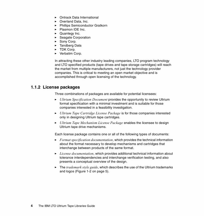
1.1.2 License packagesThree combinations of packages are available for potential licensees:
� Ultrium Specification Document provides the opportunity to review Ultrium format specification with a minimal investment and is suitable for those companies interested in a feasibility investigation.
� Ultrium Tape Cartridge License Package is for those companies interested only in designing Ultrium tape cartridges.
� Ultrium Tape Mechanism License Package enables the licensee to design Ultrium tape drive mechanisms.
Each license package contains one or all of the following types of documents:
� Format specification documentation, which provides the technical information about the format necessary to develop mechanisms and cartridges that interchange between products of the same format.
� License documentation, which provides additional technical information about tolerance interdependencies and interchange verification testing, and also presents a conceptual overview of the design.
� The trademark style guide, which describes the use of the Ultrium trademarks and logos (Figure 1-2 on page 5).
4 The IBM LTO Ultrium Tape Libraries Guide

Figure 1-2 LTO trademarks
1.1.3 Compliance verificationThe technical strategy for accomplishing format compliance verification among the licensees has been defined, and an independent Compliance Verification Entity (CVE) has been selected. In an effort to promote interchangeability of tape cartridges, the TPCs are enlisting the services of a third-party verification test company to perform specification compliance verification testing. These tests will be required annually for all companies that use the logo.
The objective of the compliance testing is to test only the ability to produce and/or read and write Ultrium cartridges that meet the format specifications. It is not an objective of this format compliance testing to evaluate Ultrium drive quality, MTBF, physical form factor, or other parameters not directly related to the LTO program formats and interchangeability. LTO program licensees have wide latitude to establish their own mechanical, electrical, and logic designs to meet the format specifications. These factors will not be tested as part of the compliance verification process.
For more details about the packages, documentation, or licensing, refer to the LTO Web site:
http://www.lto-technology.com
1.2 LTO standardsLTO Technology was originally developed for two open tape format specifications: Accelis and Ultrium. The Accelis format (fast-access) is not being developed as the Ultrium format provides adequate fast-access performance.
1.2.1 Ultrium tape formatsFigure 1-3 on page 6 shows the IBM Ultrium cartridges, which can be distinguished by color: The first generation IBM cartridge is black, and the second generation (Ultrium 2) cartridge is purple.
Chapter 1. Introduction to Linear Tape-Open (LTO) 5

Figure 1-3 IBM LTO Ultrium 1 and Ultrium 2 tape cartridges
The Ultrium tape format specification is the implementation of LTO optimized for high capacity and performance with outstanding reliability, in either a stand-alone or an automated environment. The Ultrium cartridge uses a larger single-reel design (Figure 1-3) and 1/2-inch tape to provide ultra-high storage capacity. The tape is extracted from the cartridge by the tape drive through a leader pin, and wound onto a take-up reel contained within the drive itself. This design is focused on customer requirements for very high capacity and performance, and is ideally suited for backup, restore, and archive applications. Ultrium drive technology is intended to meet the needs of the enterprise on a roadmap, or migration path, that extends well into the future. The Ultrium tape format establishes a new benchmark for large volume backup and archive.
1.2.2 LTO core technologyMulti-channel linear serpentine recording is at the core of the LTO formats. It enables an optimum balance of reliability and data integrity, performance, and high capacity. In the LTO recording format, data is written in tracks that run down the length of the tape.
The Ultrium format records either 384 tracks (Ultrium 1) or 512 (Ultrium 2) across the half-inch of tape width. This linear recording format has a serpentine characteristic. The drive mechanism will make multiple passes from the beginning of the tape to the end of the tape and back in order to read or write the full capacity of the cartridge. In the Ultrium 1 format, the 384 tracks are split into four bands of 96 tracks each. In Ultrium 2 format, the 512 tracks are split into four bands of 128 tracks each. Data is written to the innermost bands first, to provide protection to the data recorded earliest in the process, by writing it in the center, the most physically stable area on the tape. Data is also verified as it is written. On pass one of a round trip down the length of the tape and back, eight tracks are read, or written, concurrently. At the end of the tape, pass two of the round trip starts. The read/write heads are indexed and positioned over eight new tracks, and the tape reverses direction back toward the beginning of the tape to
6 The IBM LTO Ultrium Tape Libraries Guide
complete the round trip. For the next round trip, the heads are again indexed to a new position over a new group of eight tracks.
Because track densities are high, and because the tape is subject to some lateral movement as it is moved, it is critical for performance and data integrity that the read/write heads are always positioned precisely over the correct tracks. This is accomplished through a technique called timing based servo. This technique makes it possible to use high track densities, now and in the future, without changing the format of the media, and it provides the ability to read data, even with media imperfections.
In the LTO system, electronic signals are generated through the real-time reading of servo data bands that are prerecorded on the LTO tape. These signals enable the servo system to dynamically control the positioning of the read/write heads across the width of the tape. Similar magnetically based, track-following servo systems are proven in tens of thousands of tape drives in use today such as the IBM Magstar® High Performance Tape Drive.
The LTO formats also utilize advanced error correction codes for data integrity. These systems are designed to automatically correct most cross-track errors and provide data correction even if a full track is lost. Data is further protected by demarcation of bad areas of the tape (for example, where servo signals are unreliable) and through dynamic rewriting of bad blocks. Cartridge memory is embedded in the LTO cartridges. A non-contacting radio frequency module, with non-volatile memory capacity of 4096 bytes, provides for storage and retrieval of cartridge, data positioning, and user-specified information.
Chapter 1. Introduction to Linear Tape-Open (LTO) 7

8 The IBM LTO Ultrium Tape Libraries Guide

Chapter 2. LTO technology
This chapter covers the LTO format specifications in general terms, including first and second generation Ultrium. The information referring to the data cartridge, the format in which data is written, elements of the drive specification relating to that format, and the compression algorithm description, are all part of the documented LTO specification. This kind of information will be applicable to all LTO manufacturers’ product offerings in order to ensure cartridge interchangeability.
The information relating to the LTO Ultrium drive given in this chapter relates to the IBM LTO Ultrium drive, and may not be the same as those from other manufacturers in regard to such features as data rate and reliability.
This chapter also gives an overview of the IBM product offerings, which are covered in detail in later chapters.
2
© Copyright IBM Corp. 2000, 2003. All rights reserved. 9

2.1 Interleaved recordingThe drive uses an interleaved, serpentine, longitudinal recording format. The first set of eight data tracks is written from near the physical beginning of the tape to near the physical end of the tape. The head then repositions to the next set of tracks for the return. This process continues until all tracks are written and the tape is full.
The format of the recording of the data and servo tracks is defined as part of the LTO specification in order to meet the requirement for interchange between different manufacturers implementations.
2.1.1 Servo tracksServo tracks (also called bands) enable accurate positioning of the tape drive head over the data track, ensuring that the head does not stray onto an adjacent track. They are necessary to support high-data densities on the tape where the tracks are very close together. The servo bands are written at time of cartridge manufacture, before the cartridge is usable for data storage and retrieval.
Servo tracks are like lane markings on a multi-lane highway. Imagine how difficult it would be to drive on a highway without any lane markings. Lane markings help by positioning you on the lane, just as servo tracks support the drive recording head to position on the data tracks.
10 The IBM LTO Ultrium Tape Libraries Guide
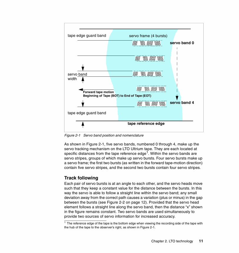
Figure 2-1 Servo band position and nomenclature
As shown in Figure 2-1, five servo bands, numbered 0 through 4, make up the servo tracking mechanism on the LTO Ultrium tape. They are each located at specific distances from the tape reference edge1. Within the servo bands are servo stripes, groups of which make up servo bursts. Four servo bursts make up a servo frame; the first two bursts (as written in the forward tape-motion direction) contain five servo stripes, and the second two bursts contain four servo stripes.
Track followingEach pair of servo bursts is at an angle to each other, and the servo heads move such that they keep a constant value for the distance between the bursts. In this way the servo is able to follow a straight line within the servo band; any small deviation away from the correct path causes a variation (plus or minus) in the gap between the bursts (see Figure 2-2 on page 12). Provided that the servo head element follows a straight line along the servo band, then the distance “x” shown in the figure remains constant. Two servo bands are used simultaneously to provide two sources of servo information for increased accuracy.1 The reference edge of the tape is the bottom edge when viewing the recording side of the tape with the hub of the tape to the observer’s right, as shown in Figure 2-1.
tape edge guard band
servo band
tape edge guard band
width
Forward tape motionBeginning of Tape (BOT) to End of Tape (EOT)
tape reference edge
servo band 0
servo band 4
servo frame (4 bursts)
Chapter 2. LTO technology 11

Figure 2-2 Magnified servo band showing a pair of servo bursts
The format specifies six nominal servo positions for Ultrium 1 and eight servo positions for Ultrium 2 within each servo band. In addition, the servo head is made up of two servo head elements to address a single servo band. This means that, using the two elements, the servo head is able to reposition within the servo band for the six (Ultrium 1) or eight (Ultrium 2) forward and reverse data wraps within each data band (Figure 2-5 on page 15). The distance between each servo position corresponds to the distance apart that the data tracks are written. For further information about the drive head and elements, see 2.4.1, “Drive head” on page 29 and Figure 2-15 on page 29.
This technology can be very finely tuned and is capable of supporting very high track densities using the same servo tracks because the currently used and defined six/eight nominal positions are basically definitions of six/eight different “x distances” between servo bursts (see Figure 2-2) and not a fixed servo track. By defining additional “x distance” positions, it is possible to increase the number of tracks on an LTO Ultrium while still using the same technology. With this technology, LTO is also able to satisfy the compatibility aspects as described in 1.1, “The LTO organization” on page 2. The Ultrium 2 drives have to use the six defined “x distances” on the Server tracks to read and write in Ultrium 1 Format.
Longitudinal positioningThe LTO servo band is designed not only for track following but also for recording the longitudinal position (LPOS). The absolute location down the length of the tape and the manufacturer data are recorded in LPOS “words,” approximately
servo band center line
12 The IBM LTO Ultrium Tape Libraries Guide

every quarter-inch (.7 cm) along the tape. The LPOS word consists of symbols constructed from bit sequences (ones and zeros); these bits are encoded within the servo frames.
Figure 2-3 Encoding bits using the servo stripes within the servo bursts
Each servo frame encodes one bit using the first pair of servo bursts. When servo stripes 2 and 3 (out of the five) are shifted inward (see Figure 2-3), this encodes a zero; when servo stripes 2 and 3 are shifted outward, this encodes a one. The LPOS word contains 36 bits and thus has a length of 36 servo frames.
Each of the 5 servo bands on the tape may be uniquely identified by the relative positions of the frames down the tape, in adjacent servo bands. The offset of the frames between servo band n and servo band n+1 are specific to each servo band (0 and 1, 1 and 2, 2 and 3, or 3 and 4). Thus the drive can move the head directly from the physical beginning of the tape to a specific logical position for reading or writing.
2.1.2 Data tracksThe area between adjacent servo bands is a data band. There are four data bands numbered 2, 0, 1, and 3, where data band number 2 is nearest the reference edge of the tape and data band 3 is farthest away, as in Figure 2-4 on page 14. The data bands are written in sequence beginning with 0 (in the center of the tape) and ending with 3.
Encoding a ONE
Encoding a ZERO
Forward tape motion (BOT to EOT)
Chapter 2. LTO technology 13
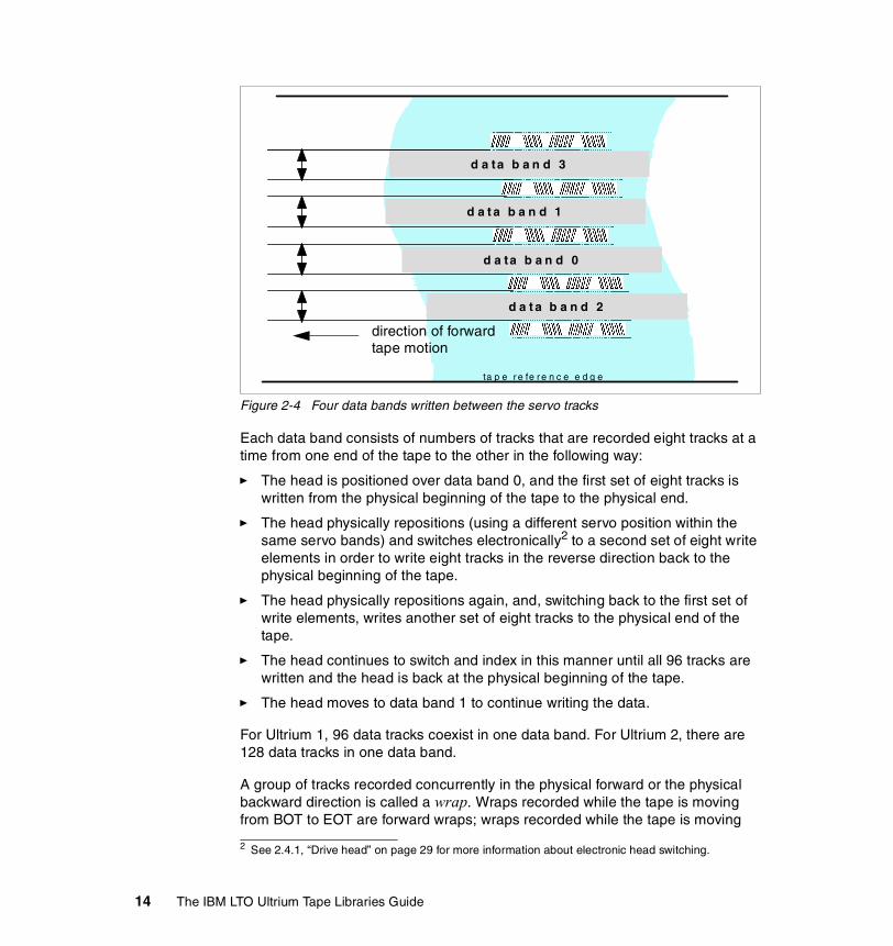
Figure 2-4 Four data bands written between the servo tracks
Each data band consists of numbers of tracks that are recorded eight tracks at a time from one end of the tape to the other in the following way:
� The head is positioned over data band 0, and the first set of eight tracks is written from the physical beginning of the tape to the physical end.
� The head physically repositions (using a different servo position within the same servo bands) and switches electronically2 to a second set of eight write elements in order to write eight tracks in the reverse direction back to the physical beginning of the tape.
� The head physically repositions again, and, switching back to the first set of write elements, writes another set of eight tracks to the physical end of the tape.
� The head continues to switch and index in this manner until all 96 tracks are written and the head is back at the physical beginning of the tape.
� The head moves to data band 1 to continue writing the data.
For Ultrium 1, 96 data tracks coexist in one data band. For Ultrium 2, there are 128 data tracks in one data band.
A group of tracks recorded concurrently in the physical forward or the physical backward direction is called a wrap. Wraps recorded while the tape is moving from BOT to EOT are forward wraps; wraps recorded while the tape is moving
2 See 2.4.1, “Drive head” on page 29 for more information about electronic head switching.
d a ta b a n d 3
d a t a b a n d 1
d a ta b a n d 0
d a t a b a n d 2
ta p e r e fe r e n c e e d g e
direction of forward tape motion
14 The IBM LTO Ultrium Tape Libraries Guide

from EOT to BOT are reverse wraps. The wraps are recorded in a serpentine fashion, as described: a forward wrap, then a reverse wrap. They are numbered sequentially in the order that they are processed, starting with wrap 0. Thus, for Ultrium 1 six forward wraps and six reverse wraps make up a data band. For Ultrium 2, eight forward and eight reverse wraps make up a data band. The individual tracks within a wrap are interleaved with tracks from other wraps; in other words, adjacent tracks are not part of the same wrap. (See Figure 2-5.)
Figure 2-5 Portion of data band showing Ultrium 1 track-writing sequence
This figure expands on Figure 2-4 on page 14 to illustrate the sequence in which the tracks are written. One data band is magnified3 to show an area written by two adjacent write head elements (from the total of eight); this is one quarter of the width of the data band. You can see that the tracks are written in an inward spiral (serpentine) manner; the first and second tracks are farthest away from one another while the 11th and 12th tracks are adjacent to one another.
3 Refer to 2.4.1, “Drive head” on page 29, and Figure 2-15 on page 29, to see the structure of the eight-element head.
1st3rd5th7th9th11th
12th10th8th6th4th2nd
1st3rd5th7th9th11th
12th10th8th6th4th2nd
direction buffers(separating tracks witten in different directions)
forward tape motion(BOT to EOT)
group of tracks written by one of
the 8 write elements
group of tracks written by adjacent
write element
Chapter 2. LTO technology 15

The space between tracks written in opposing directions is called a direction buffer. This space is designed to minimize magnetic interference between tracks written in opposite directions (cross-track interference).
Read/verify elements are built into the tape head in the drive. The data is written by the write elements and then immediately passes the read/verify elements and is checked for errors. If any errors are found, the block of data is rewritten farther down the tape.
The total number of data tracks across the width of the tape is 384 for Ultrium 1, numbered 0 through 383. For Ultrium 2, 512 tracks are used. Track numbering is unrelated to the sequence in which the tracks are written: data track 383/512 is the closest to the reference edge of the tape, and data track 0 is farthest away.
2.1.3 Linear densityThe linear density for LTO 1 is 4880 bits per mm. The linear density was improved for LTO 2 to 7398 bits per mm.
2.2 Data compressionThe LTO Consortium created a superior data compression technique know as LTO Data Compression (LTO-DC). Though an excellent data compression algorithm, ALDC (adaptive lossless data compression), already exists, ALDC function is not optimized for incompressible data such as encrypted or previously compressed data. For incompressible data, it is usually best not to apply any data compression algorithm, but rather to simply pass the input data out to the compressed data stream directly (pass-thru). Given the variations in data, there are times when ALDC is desirable and times when a simple pass-thru is better. For instance, if using ALDC-based data compression, it would be best if all segments of incompressible data were to be recorded without expansion by using a pass-thru technique instead. Figure 2-6 is a block diagram illustration of the LTO-DC data compression technique using the two schemes.
Figure 2-6 LTO-DC block diagram
16 The IBM LTO Ultrium Tape Libraries Guide

Note that no standardization of when to scheme swap when compressing data was specified by LTO-DC. LTO-DC was approved by ECMA as SLDC [streaming lossless data compression] standard, as explained at:
http://www.ecma-international.org/publications/standards/ECMA-321.htm
Because no standardization is specified, all vendor implementations may do scheme swapping differently. What is specified and tested is that the resultant compressed data stream is decompressible by the defined set of LTO-DC rules. This enables interchange between drives from the three companies. Each vendor’s Ultrium drive has been shown to be able to read and decompress the LTO-DC streams of the others.
Embedded codewordsLTO-DC uses embedded codewords to enable swapping between the two schemes. ALDC is referred to as Scheme 1, and pass-thru is referred to as Scheme 2. Both methods are used. However, only one is used to output any given data byte, though different bytes in a record might be output in different schemes. Thus, if a given record begins with compressible data it can be output in Scheme 1, and if the nature of the data changes inside of the record and it becomes incompressible (as embedded control data or an array of incompressible data), a scheme swap can be performed to allow outputting the incompressible data in Scheme 2. Similarly a scheme swap can be performed to revert to Scheme 1 if the data becomes compressible again. A scheme swap is denoted in the compressed data stream via one of four embedded codewords. As an example, one 13-bit codeword basically means all following data is to be decompressed as Scheme 1 until another scheme swapping codeword is encountered. Embedded codewords are also used to delineate record boundaries and filemarks. Having record boundaries demarked within the output compressed data stream, rather than by pointers maintained in a separate directory table, has a number of advantages. First, from a storage point of view, it is more efficient as it enables greater capacity. Second, the insertion of these codewords enables higher-speed data streaming because they can be managed by the compression engine without microprocessor involvement. Both of these features are especially useful for small records. Typically, backup applications will send 512-byte, 4-KB, 32-KB, or 256-KB records to a backup tape drive. For small records such as 512 bytes, the improved format efficiency of the embedded control is substantial. By reducing required microprocessor involvement it allows superior transfer rates to the drives. This is why LTO tape drives offer high capacity tape backup, as well as drive transfer rates far better than other midrange backup tape drives—and are superior even to some costly, high-end tape drives.
The ability to swap between ALDC and a pass-thru mode gives a tape drive the power to automatically adapt to the incoming data stream.
Chapter 2. LTO technology 17

2.3 Tape cartridgeThe Ultrium cartridge is a single-reel cartridge. This means the whole tape is wrapped around a single reel when the cartridge is not loaded in a drive. During the loading process, the threader of the drive catches the leader pin of the tape and threads it through the drive and the machine reel. During the read/write process the tape is stored on the machine reel and the cartridge.
Two views of the tape cartridge are shown in Figure 2-7 and Figure 2-8 on page 19.
Figure 2-7 Ultrium cartridge view from top and rear
The cartridge is approximately 10.2 cm long, 10.5 cm wide, and 2.2 cm high (approximately 4 x 4.16 x 0.87 inches). The cartridge contains 1/2-in (12.6 mm), metal-particle tape with a highly dense recording area. The Ultrium 1 spec describes four types of cartridges, each with a different tape length and, therefore, capacity. At this time, only one cartridge type is generally available, with a tape length of 610 m (2000 feet) providing 100 GB of native data and 200 GB of compressed data (assuming 2:1 compression). There is only one standard Ultrium 2 cartridge type and hence only one tape length of 610m (2000 feet). The native capacity of the Ultrium 2 cartridge is 200 GB (400 GB compressed assuming 2:1 compression).
Figure 2-8 on page 19 shows some of the components of the cartridge.
write protect switch
arrow indicating direction of loading into the drive
sliding door accessto tape for read/write
label area(rear)
notch for drive loadmechanism
notch for roboticgripper mechanism
18 The IBM LTO Ultrium Tape Libraries Guide

Figure 2-8 Ultrium cartridge view from top and front
The labelled parts are:
� Grips: Molded areas on the cartridge casing designed as finger grips for manual loading.
� Label area: Located at the designated area at the rear of the cartridge where the adhesive bar code label is applied.
� Sliding door: Cartridge door (shown in Figure 2-7 on page 18) that protects the tape from contamination whenever the cartridge is out of the drive. Behind the door, the tape is threaded onto a leader pin (shown in detail in Figure 2-9 on page 20), which is used to pull the tape from the cartridge for use. A locking mechanism prevents the media from unwinding when the cartridge is not located in the drive.
� Notches: Two sets of moulded notches in the cartridge casing located on the sides near the rear. The first pair enables the robotic gripper to pull the cartridge out of the drive mouth once the cartridge has been unloaded; the second pair enables the drive to grip the cartridge and pull it into the loading position inside the drive.
� Mis-insertion protection: A cut-out in the front side of the cartridge casing that prevents the cartridge from being inserted into the drive in the wrong orientation. This feature prevents the use of unsuitable cartridges of similar, but not identical, construction.
direction ofloading intodrive (front)
mis-insertion
cartridge case cut awayto show location of LTO-CM
rear (label area)
finger grips
cut-outprotection
notch fordrive-loadmechanism
notch forrobotic grippermechanism
Chapter 2. LTO technology 19
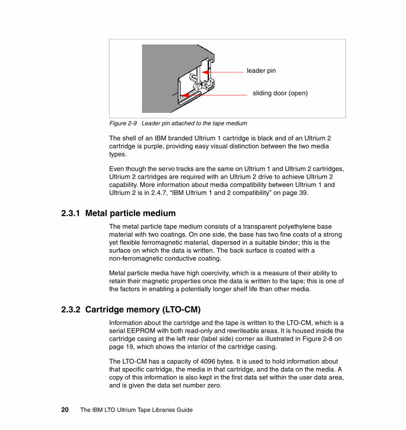
Figure 2-9 Leader pin attached to the tape medium
The shell of an IBM branded Ultrium 1 cartridge is black and of an Ultrium 2 cartridge is purple, providing easy visual distinction between the two media types.
Even though the servo tracks are the same on Ultrium 1 and Ultrium 2 cartridges, Ultrium 2 cartridges are required with an Ultrium 2 drive to achieve Ultrium 2 capability. More information about media compatibility between Ultrium 1 and Ultrium 2 is in 2.4.7, “IBM Ultrium 1 and 2 compatibility” on page 39.
2.3.1 Metal particle mediumThe metal particle tape medium consists of a transparent polyethylene base material with two coatings. On one side, the base has two fine coats of a strong yet flexible ferromagnetic material, dispersed in a suitable binder; this is the surface on which the data is written. The back surface is coated with a non-ferromagnetic conductive coating.
Metal particle media have high coercivity, which is a measure of their ability to retain their magnetic properties once the data is written to the tape; this is one of the factors in enabling a potentially longer shelf life than other media.
2.3.2 Cartridge memory (LTO-CM)Information about the cartridge and the tape is written to the LTO-CM, which is a serial EEPROM with both read-only and rewriteable areas. It is housed inside the cartridge casing at the left rear (label side) corner as illustrated in Figure 2-8 on page 19, which shows the interior of the cartridge casing.
The LTO-CM has a capacity of 4096 bytes. It is used to hold information about that specific cartridge, the media in that cartridge, and the data on the media. A copy of this information is also kept in the first data set within the user data area, and is given the data set number zero.
sliding door (open)
leader pin
20 The IBM LTO Ultrium Tape Libraries Guide

Communication between the drive and the LTO-CM uses a contactless low-level radio frequency (RF) field generated (in the IBM implementation) by the drive. The LTO-CM is non-volatile storage updated using the RF field; it requires no additional power source. This type of technology has an expected shelf life of more than 30 years.
There are a number of distinct data fields within the LTO-CM, shown in Table 2-1. The fields align to 32-byte boundaries, as this is the defined block access size.
Table 2-1 Data fields stored in the LTO-CM
Although transparent to the user, keeping this kind of information enhances the efficiency of the drive and cartridge. Data and block locations are stored in memory; for example, the end-of-data location is stored, so that when the tape is next loaded, the drive can use the fast locate function to move directly to the recording area and begin recording. Storing data about the age of the cartridge, how many times it has been loaded, and how many errors it has accumulated
LTO-CM information Read/write
LTO-CM manufacturer’s data
Tape labela
a. This field contains information about the tape, including a 10-byte field with thetape serial number; it is a read-only area and does not contain the volume label,which could be changed if the tape is reinitialized.
Read-only
Media manufacturer information
Initialization datab
b. This is a restricted-write field that is updated with changes when the tape isreinitialized.c. This is a field for application data (such as the volume label) to be stored in theCM. However, currently there is no SCSI function available to support writing tothat area.
Restricted write capability
Cartridge status and tape alert flags
Usage information
Tape write pass
Tape directory Read or write
End-of-data information
Mechanism related
Application specific datac
Vendor unique data
Chapter 2. LTO technology 21

aids in determining the reliability of the cartridge. It is of particular value if this data is stored with the cartridge itself, so that whenever it is mounted on any host system, the history is accessible.
This is not the first tape product where information has been kept on the cartridge; however, previously it has been written onto the tape medium itself in a non-user-accessible portion of the tape before the beginning-of-tape (BOT) marker, for example, as in the IBM 3590 tape drive.
2.3.3 Barcode labelEach data and cleaning cartridge processed by an Ultrium tape library should bear a barcode label. (This is mandatory for libraries that have an installed barcode reader such as the IBM 3584.)
The label, as shown in Figure 2-10, contains a human-readable volume serial number or volume label, and a machine-readable barcode.
Figure 2-10 Barcode label example
The bar code format is:
� Quiet zones (at each end of the bar code)
� A start character (indicating the beginning of the label)
� A six-character volume label
22 The IBM LTO Ultrium Tape Libraries Guide

� A two-character cartridge media-type identifier (L1 or L2), which identifies the cartridge as an LTO cartridge (‘L’) and indicates that the cartridge is the first (‘1’) or second generation (’2’)
� A stop character (indicating the end of the label)
When read by the library’s barcode reader, the barcode identifies the cartridge’s volume label to the tape library. The barcode volume label also indicates to the library whether the cartridge is a data, cleaning, or diagnostic cartridge.
Tape cartridges are often supplied with the labels already attached, or you can attach a label yourself. Operators must handle the cartridges and barcode labels in accordance with the instructions in the operator guides supplied with the products. You must ensure that labels are removed cleanly, reapplied carefully, in good condition, and not obscured or damaged. The Ultrium cartridge features a recessed area for the label (see Figure 2-7 on page 18). The label must be applied only in the recessed label area; if it extends outside of the area it can cause loading problems in the drive.
2.3.4 Volume label formatThe LTO cartridge label uses the USS-39 barcode symbols. A description and definition is available from the Automatic Identification Manufacturers (AIM) specification document Uniform Symbol Specification (USS-39) and ANSI MH10.8M-1993 ANSI Bar code Specification.
A cartridge’s volume label consists of exactly 6 characters, starting from the left. Except for cleaning and diagnostic cartridges, these 6 characters are limited to the following ASCII characters:
� Upper-case A-Z (ASCII character code: 41h-5Ah)� 0-9 (ASCII character code: 30h-39h)
The volume label must consist of exactly six, all upper-case alphabetical, all numeric, or alphanumeric characters, such as ABCGVE, 123621, or F8H5N9. It cannot consist of fewer than six characters.
A volume label format of CLNUnn represent a universal cleaning cartridge. A volume label of the form CLNvnn is used for a unique cleaning cartridge, where v is an alphanumeric identifier that represents the vendor of a drive-unique cleaning cartridge. (An IBM-unique cleaner cartridge uses the label format CLNInn.) This identifier is logged in the vendor information pages in the Ultrium tape drive.
A volume label of the form DG(space)vnn is used for diagnostic and service cartridges. The drive uses the ‘v’ to determine if the drive-unique diagnostic
Chapter 2. LTO technology 23
cartridge is loaded. The ‘nn’ represents a specific cartridge and is logged in the vendor information pages in the Ultrium tape drive.
The internal and external labels on a cartridge need not match; this means that the volume label on the bar code label need not match the volume label recorded on the tape in the tape label area when it is initialized. However, it is generally preferable for them to match to avoid confusion.
You will find more detailed information in the LTO Label specification at:
http://www.storage.ibm.com/media/
2.3.5 Write protect switchThe write protect switch is located at the front of the cartridge to the left of the bar code label (see Figure 2-7 on page 18). The position of the write-protect switch on the tape cartridge determines whether you can write to the tape; you cannot write to the tape when the switch is pushed to the right. When the write protect switch is set to inhibit writing, a visual lock mark such as a padlock will be visible.
In most cases, backup and recovery host application software is used to achieve the most benefit from using an LTO system. It is better to rely on the host application software to write-protect your cartridges rather than manually setting the write protect switch. This allows the host software to identify a cartridge that no longer contains current data and is eligible to become a scratch cartridge. If the switch is set and the host application sets the cartridge to scratch status, the tape drive will not be able to write new data to the tape.
2.3.6 Cleaning the cartridgeCartridges that are physically dirty on the outside of the casing can reduce the reliability of an Ultrium tape library as well as cause the loss of recorded data. If dirt appears on the cartridge, you can wipe the outside surfaces with a lint-free cloth, which may be lightly moistened with the manufacturer’s recommended tape unit cleaner or equivalent.
When cleaning a tape cartridge, do not allow anything wet (including the cleaning fluid) to contact the tape inside the casing. Make sure that all cartridge surfaces are dry before the cartridge is inserted in a drive.
2.3.7 Cartridge lifeThe magnetic tape inside the cartridge is made of highly durable materials. However, the tape wears after repeated cycles. Eventually, such wear can cause an increase in tape errors, records of which are stored in the LTO-CM. This
24 The IBM LTO Ultrium Tape Libraries Guide

means that cartridge performance can be tracked and monitored, enabling predictive failure analysis and enhancing data integrity. This tracking is done automatically, and the drive issues a message when errors on the tape exceed a certain threshold.
The IBM Ultrium Data Cartridge has a usable life of 5000 load and unload cycles in a typical office computer environment.
The data recorded on the cartridge has an archive storage life of 30 years minimum with less than 5% loss in demagnetization, when the cartridge is stored at 16° C to 25° C, 20% to 50% non-condensing humidity, and wet bulb temperature of 26° C maximum.
2.3.8 Cleaning cartridgeTo support customer and application requirements and expectations for cleaning, each LTO drive vendor used to provide its own cleaning cartridge specifically for its Ultrium drives. To avoid potential interoperability problems, the LTO consortium decided to introduce a universal cleaning cartridge. IBM offers only the universal cleaning cartridge.
The IBM Ultrium LTO tape drive was intentionally designed to not require cleaning but rather to be self-monitoring and self-cleaning. Therefore the IBM recommendation is not to manually clean the tape drive regularly, but rather to use the automatic cleaning function provided with the library or by your application. Each drive determines when it needs to be cleaned and alerts the library or your application.
The cleaner cartridge can be used a maximum of 50 times to prevent recontamination of drive surfaces.
2.3.9 Cartridge handlingTape cartridges are tough packages made of inexpensive materials capable of storing tremendous amounts of data and approaching data densities of hard disks. They can survive for years in library environments where they are being gripped and poked, loaded and unloaded. But we recommend treating tape cartridges in a similar fashion to hard disk drives. Here are some suggestions to protect your data on tape cartridges.
Ensure that proper procedures are in place to cover media handling, and make sure that anyone who handles cartridges has been trained in those procedures.
Chapter 2. LTO technology 25

Media shipping and handling: proceduresShip cartridges in their original packaging, or preferably, ship/store in jewel cases. Use only recommended shipping cases that securely hold the cartridges in their jewel cases for transportation. Turtle Cases from Perm-A-Store at www.turtlecase.com, shown in Figure 2-11, have been tested and found to be satisfactory.
Figure 2-11 Turtle case
Never ship a cartridge in a commercial shipping envelope without boxing or packaging. If shipping in cardboard or similar boxes:
� Double-box the cartridges with padding between the boxes, as shown in Figure 2-12 on page 27.
� Pack snugly so cartridges do not rattle around.
� If possible, place cartridges in polyethylene plastic wrap or bags to help seal out dust, moisture, and other contaminants.
26 The IBM LTO Ultrium Tape Libraries Guide
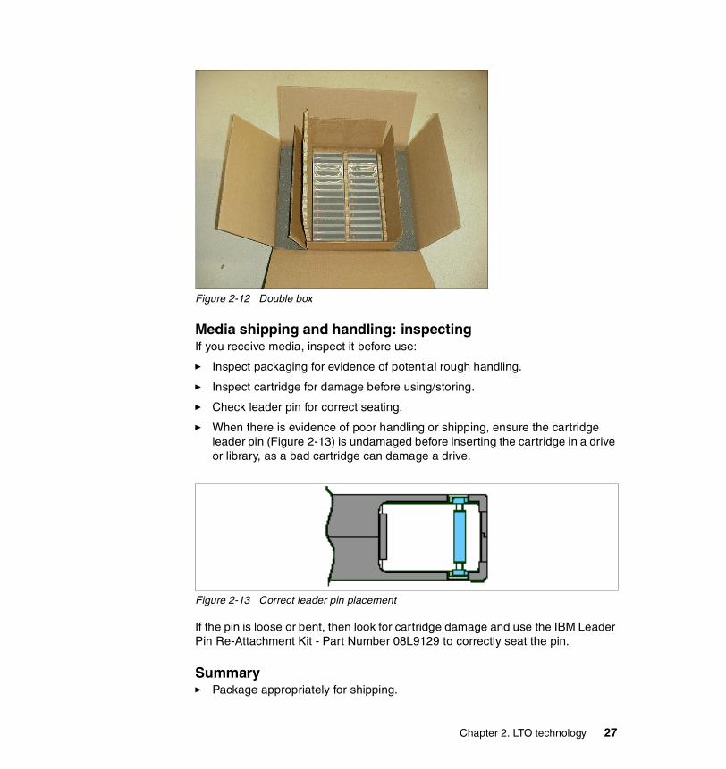
Figure 2-12 Double box
Media shipping and handling: inspectingIf you receive media, inspect it before use:
� Inspect packaging for evidence of potential rough handling.
� Inspect cartridge for damage before using/storing.
� Check leader pin for correct seating.
� When there is evidence of poor handling or shipping, ensure the cartridge leader pin (Figure 2-13) is undamaged before inserting the cartridge in a drive or library, as a bad cartridge can damage a drive.
Figure 2-13 Correct leader pin placement
If the pin is loose or bent, then look for cartridge damage and use the IBM Leader Pin Re-Attachment Kit - Part Number 08L9129 to correctly seat the pin.
Summary� Package appropriately for shipping.
Chapter 2. LTO technology 27
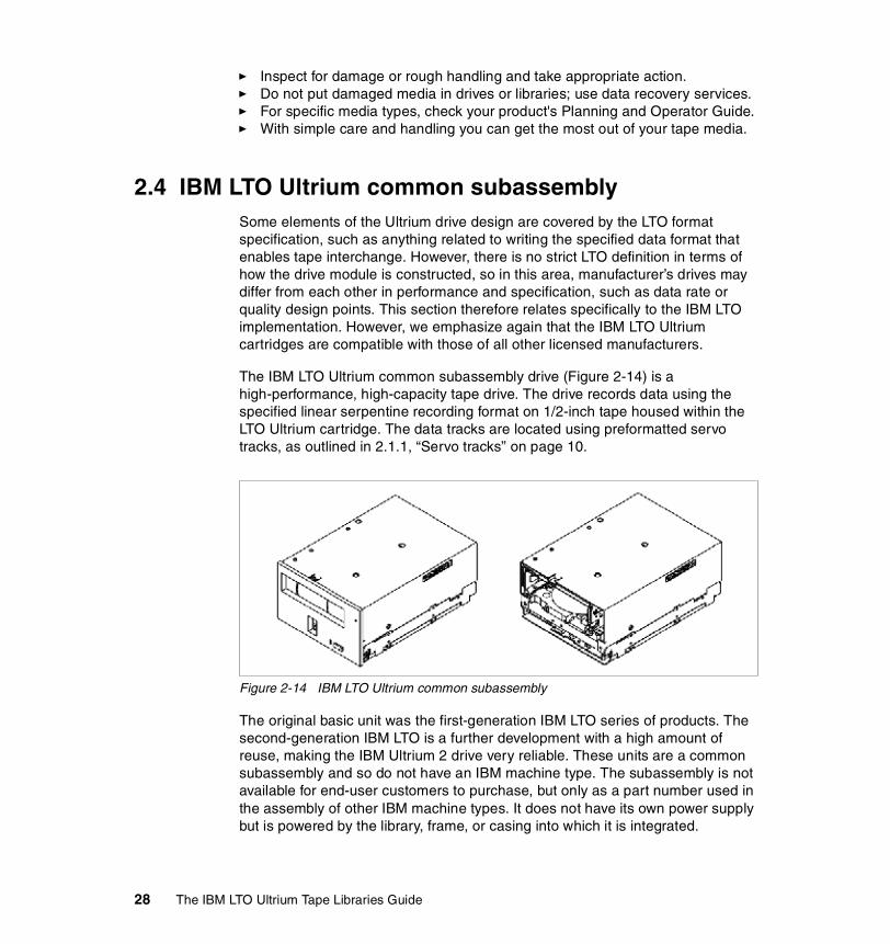
� Inspect for damage or rough handling and take appropriate action.� Do not put damaged media in drives or libraries; use data recovery services.� For specific media types, check your product's Planning and Operator Guide.� With simple care and handling you can get the most out of your tape media.
2.4 IBM LTO Ultrium common subassembly Some elements of the Ultrium drive design are covered by the LTO format specification, such as anything related to writing the specified data format that enables tape interchange. However, there is no strict LTO definition in terms of how the drive module is constructed, so in this area, manufacturer’s drives may differ from each other in performance and specification, such as data rate or quality design points. This section therefore relates specifically to the IBM LTO implementation. However, we emphasize again that the IBM LTO Ultrium cartridges are compatible with those of all other licensed manufacturers.
The IBM LTO Ultrium common subassembly drive (Figure 2-14) is a high-performance, high-capacity tape drive. The drive records data using the specified linear serpentine recording format on 1/2-inch tape housed within the LTO Ultrium cartridge. The data tracks are located using preformatted servo tracks, as outlined in 2.1.1, “Servo tracks” on page 10.
Figure 2-14 IBM LTO Ultrium common subassembly
The original basic unit was the first-generation IBM LTO series of products. The second-generation IBM LTO is a further development with a high amount of reuse, making the IBM Ultrium 2 drive very reliable. These units are a common subassembly and so do not have an IBM machine type. The subassembly is not available for end-user customers to purchase, but only as a part number used in the assembly of other IBM machine types. It does not have its own power supply but is powered by the library, frame, or casing into which it is integrated.
28 The IBM LTO Ultrium Tape Libraries Guide

The IBM machine types that integrate the subassembly are described in 2.5, “The IBM LTO Ultrium family of tapes and libraries” on page 44, and in more detail in later chapters. The subassembly is sold on the OEM market to other LTO library manufacturers. The common subassembly is a single field replaceable unit (FRU): that is, if it fails the whole unit is replaced and no parts or subassemblies within the unit are replaced when the drive is maintained by a service representative.
2.4.1 Drive headWhen the cartridge is inserted into the drive, a threading mechanism pulls the leader pin and attached tape (see Figure 2-9 on page 20) out of the cartridge, across the read/write head, and onto a non-removable take-up (machine) reel. The head can then read or write data from or to the tape.
The drive has a 2 x 8 element head, reading or writing data eight tracks at a time (see Figure 2-15). The head is sized to cover the width of a data recording band (approximately a quarter of the tape width; see Figure 2-4 on page 14). Unlike the IBM 3590, for example, it does not cover the whole width of the tape.
Figure 2-15 Eight-element head (one set of heads shown) and servo elements
The write elements are immediately followed by read/verify elements, so there are in fact two sets of eight head elements (eight write elements and eight read elements) to allow the tape to write in the forward and reverse directions down the length of the tape. The head switches electronically from one set to another as the tape changes direction, as in Figure 2-16 on page 30, which shows two enlarged pairs of head elements and the direction indicators. Two sets of heads (r-w and w-r) are required because the tape is written and read in both directions.
0 1 2 3 4 5
servo positionswithin servo band
0 1 2 3 4 5
servo positionswithin servo band
8 data tracks
2 x 2 servo elements
2 x 8 head elements
Chapter 2. LTO technology 29

Figure 2-16 Allocation of read and write heads for forward and reverse wrap
The mechanism for writing data is explained in section 2.1.2, “Data tracks” on page 13.
There are four servo elements used, two for each set of eight read/write elements. The head actually uses both servo tracks at each edge of the data band it is writing for increased accuracy in track-following, so there are two servo elements at each end of the head. As an example, Figure 2-15 on page 29 shows a diagram of the top servo element 1 following servo position 3, which would be used for the sixth wrap (a reverse wrap) in a data band; the diagram is not to scale. If you need more information about this topic, an animated explanation can be found in the LTO Ultrium technology primers on the LTO Web site at:
http://www.lto-technology.com/newsite/html/about_tech.html
Note that the animation is designed to provide a basic understanding of LTO technology and does not provide the same level of detail outlined here.
2.4.2 Data compressionAs describes in 2.2, “Data compression” on page 16, the implementation of the data compression may be different from vendor to vendor.
One implementation appears to only perform scheme swapping on a record basis. For example, if the compressed data stream output for a given record is larger for Scheme 1 than for Scheme 2, then the entire record is output in Scheme 2. The second implementation seems to react to data on an ongoing
0 1 2 3 4 5
servo positionswithin servo band
0 1 2 3 4 5
servo positionswithin servo band
s
s
s
s
direction of tape movement
r
w
w
r
r
w
w
r
r
w
w
r
r
w
w
r
r
w
w
r
r
w
w
r
r
w
w
r
r
w
w
r
direction of tape movement
30 The IBM LTO Ultrium Tape Libraries Guide

basis so that if the drive perceives that the nature of the data in a record has changed from compressible to incompressible then a Scheme 2 swap is enabled and the incompressible data from there on is output in Scheme 2. This is not always advantageous because the incompressible data may again transition to compressible even before that scheme swap has occurred. Each scheme swap codeword output is 13 bits long. Therefore, to swap to a scheme and swap back costs 26 bits. The compression gain following the first scheme swap may benefit more than 26 bits over the previous scheme; if so, the swap was well-advised. If not, then the scheme swap actually increased the size of the output compressed data stream and reduced the compression rather than increase it. There is a chance of this occurring if data compressibility is inferred by having the data compression engine observe how data that has already been output from the compression engine was compressed—that is, only by viewing data in the past. The only way to adapt via scheme swapping within records, without being susceptible to inadvertent data expansion, is to use the IBM-patented scheme swapping technique. This method is preferred since it effectively looks at data ahead, rather than behind. In the IBM implementation, a scheme swap is not automatically generated unless there appears to be more compression gain within the look ahead buffer than it costs to scheme swap, and then swap back. This is advantageous as small bursts of compressible data within an otherwise incompressible file may not make it worthwhile to scheme swap. If a scheme swap is optimal, the IBM implementation puts the scheme swap out where the change in data compressibility occurs, giving maximum advantage. For more information, see:
http://www.storage.ibm.com/hardsoft/tape/lto/prod_data/whitepaper_compression.pdf
This paper shows how the IBM LTO-DC embodiment achieved superior data compression to another vendor’s LTO drives by performing scheme swapping simultaneously with changes in the compressibility of the data, enabled by effectively looking 64 bytes ahead in the input data stream.
2.4.3 InterfacesThe IBM LTO Ultrium drive is available with a choice of interfaces, either SCSI LVD or HVD, or FC. When ordering an IBM product offering, you choose the drive interface. You cannot change the interface on the drive; if you want a different interface, you must replace the drive assembly.
Common interfaces for tape drivesHistorically, SCSI connections were used for attachment of tape drives and libraries to open systems. Fibre Channel connections using SANs are becoming increasingly common.
Chapter 2. LTO technology 31

SCSI single endedThis was the most common form of SCSI signaling. Many removable drives, scanners, and almost all 50-pin SCSI devices fit into this category. Often you do not see “SE” or “single-ended” written on the documentation; if a device does not specifically say LVD, Ultra2 Wide, differential, or some similar definition, then it is probably single-ended. Typically, single-ended devices support a total bus length of 1.5 meters (5 ft) or less.
IBM high-performance SCSI tape drives (IBM 3590, IBM 3570, and LTO Ultrium drives) are all differential-attached drives, not single-ended.
SCSI differential (HVD)HVD (often referred to as just “differential”) uses differential signaling. The idea behind differential signals is that each bus signal is carried on a pair of wires. The first wire of the pair carries the same type of signal as single-ended SCSI. However, the second wire of the pair carries its logical inversion. The receiver of the signals takes the difference of the pair (hence the name), which makes it less susceptible to noise and capable of supporting greater cable lengths. HVD and single-ended SCSI are completely incompatible with each other.
In general, IBM HVD tape devices support an overall bus length of 25 m, using point-to-point or multi-drop interconnection (daisy-chaining). For each daisy-chain device you have to reduce the maximum cable length by 0.5 m.
SCSI differential (LVD)This newer differential interface implementation, LVD uses less power than the HVD differential interface, and allows the higher speeds of Ultra-2 SCSI. LVD requires 3.3 V dc instead of 5 V dc for HVD.
LVD is sometimes referred to as Ultra-2 Wide SCSI, which is a general marketing term for 16-bit Fast-40 or 80 MB/s. Only LVD and HVD could potentially run in Ultra-2 Wide mode, and only LVSD in current commercially available products.
IBM LVD tape devices support a bus length of 25 m point-to-point, and 12 m using multi-drop interconnection (daisy-chaning). For each daisy-chain device you have to reduce the maximum cable length by 0.5 m.
The terms fast, wide, and ultra indicate characteristics that are separate from those implied by differential, single-ended, and high or low voltage. Table 2-2 on page 33 shows the SCSI terms used to describe different host and device adapters and what they imply in terms of bus width and speed.
32 The IBM LTO Ultrium Tape Libraries Guide

Table 2-2 SCSI terms and characteristics
Note that a faster bus does not imply that an attached device will support that data rate, but that multiple devices can operate on the bus at that maximum speed. For a detailed table of SCSI terms and related specifications, refer to the SCSI Trade Association Web site at:
http://www.scsita.org/terms/scsiterms.html
To ensure best performance, if possible, avoid daisy-chaining.
FC-ALThe first FC-connected tape drives, such as IBM 3590 and IBM Ultrium 1, used Fibre Channel - Arbitrated Loop (FC-AL) attachment. Because IBM tape devices support public loop, those devices were seen in a SAN fabric as regular devices with a WWN, when connected to a switch supporting FC-AL login, such as Brocade and Inrange Switches and Directors.
FC switched fabric - N-PortNewer tape devices, such as IBM Ultrium 2, use switch fabric connection (N-Port). This eliminates the need for edge loop-switches that support FC-AL login, such as the MC-Data ES1000.
Connector typesWhen ordering cables, pay careful attention to the type of connector on both the cable and device, so that everything will correctly plug in together. These are the major connector types.
SCSI term Bus width (bits)
Speed (MB/s) Max. length Max. devices
SCSI 8 5 6 m 7
Fast SCSI 8 10 3 m 7
Fast Wide SCSI
16 20 3 m 15
Ultra (Wide) SCSIHVD
16 40 25 m 15
Ultra (Wide) SCSI 2LVD
16 80 25 m / 12 m 15
Ultra 160 SCSILVD
16 160 25 m / 12 m 15
Chapter 2. LTO technology 33

SCSI HD68The HD68 connector is the normal 68-pin SCSI connector. All IBM LTO SCSI Drives, except the drives in the 3584, have an HD68 connector. Before June 12, 2001, all LTO tape drives in the 3584 used HD68 connectors.
Figure 2-17 HD68 connector
SCSI VHDCIThe VHDCI (Very High Density) connector is a mini-SCSI connector, about half the width of the HD68 connector. All IBM LTO drives in the 3584 have a VHDCI connector.
Figure 2-18 VHDCI connector
FC SCThe duplex SC connector is a low-loss, push/pull fitting connector. The two fibers each have their own part of the connector. The connector is keyed to ensure correct polarization (transmit to receive and vice-versa) when connected. Most 1 Gb SAN devices, including IBM Ultrium 1 FC drives, use SC connectors.
FC LCConnectors that plug into SFF or SFP devices are called LC connectors. A duplex version is also used so that the transmit and receive are connected in one step. The main advantage of these LC connectors over SC connectors is that they use a smaller form factor and so manufacturers of Fibre Channel components can provide more connections in the same amount of space.
Most 2 Gb SAN devices, including IBM Ultrium 2 FC drives, use LC connectors.
34 The IBM LTO Ultrium Tape Libraries Guide

Available interfaces for IBM Ultrium 1IBM Ultrium 1 drives offer these connection types:
� Ultra2/Wide Low Voltage Differential (LVD) SCSI using VHDCI connector� Ultra/Wide High Voltage Differential (HVD) SCSI using VHDCI connector� FC-AL, 1 Gbps using SC connector
Available interfaces for IBM Ultrium 2IBM Ultrium 2 drives offer these connection types:
� Ultra 160 Low Voltage Differential (LVD) SCSI using VHDCI connector� Ultra/Wide High Voltage Differential (HVD) SCSI using VHDCI connector� Switched fabric 2 Gbps using LC connector
2.4.4 PerformanceIBM LTO drives provide high performance and will continue to improve with each new generation of products. If you run applications that are highly dependent on tape-processing speed, you can exploit the significant performance provided by the Ultrium tape drives.
IBM Ultrium 1The IBM LTO Ultrium 1 tape drive has these performance characteristics:
� 15 MB/s native sustained data transfer rate� 30 MB/s sustained data transfer rate at 2:1 compression� 60 MB/s maximum sustained data rate (at maximum compression)� 100 MB/s burst data transfer rate for Fibre Channel� 80 MB/s burst data transfer rate for Ultra-2 SCSI LVD drives� 40 MB/s burst data transfer rate for Ultra SCSI HVD drives� 20 s nominal load-to-ready time� 18 s nominal unload time� 73 s average search time to first byte of data� 110 s maximum rewind Time� 4 m/s read/write speed� 6 m/s search/rewind speed � 32 MB buffer
IBM LTO Ultrium drives provide efficient tape operations and relief to users who have difficulty completing tape activities in the time available. If you have limited system backup windows, or if you have large amounts of disk data to back up, Ultrium tape drives are ideal.
By using the built-in data-compression capability of the Ultrium drive, you can potentially achieve greater data rates than the uncompressed data rate.
Chapter 2. LTO technology 35

However, the actual throughput is a function of many components, such as the host system processor, disk data rate, block size, data compression ratio, SCSI bus capabilities, and system or application software. Installing multiple tape drives in general (or more than two in the case of IBM LTO) on a single SCSI bus may adversely affect data transfer rates.
IBM Ultrium 2The IBM LTO Ultrium 2 drives provide more than twice the performance over IBM Ultrium 1 with sustained data rates of 35 MB/s native and 70 MB/s with 2:1 compression. IBM Ultrium 2 has faster load and unload time, faster data access time, faster rewind time, and faster cartridge fill time compared with IBM Ultrium 1.
The IBM LTO Ultrium 2 tape drive has these performance characteristics:
� 35 MB/s native sustained data transfer rate� 70 MB/s sustained data transfer rate at 2:1 compression� 110 MB/s maximum sustained data rate (at maximum compression)� 200 MB/s burst data transfer rate for Fibre Channel� 160 MB/s burst data transfer rate for Ultra 160 SCSI LVD drives� 40 MB/s burst data transfer rate for Ultra SCSI HVD drives� 15s nominal load-to-ready time� 15 s nominal unload time� 49s average search time to first byte of data� 80 s maximum rewind Time� 6.2m/s read/write speed� 8m/s search/rewind speed � 64 MB buffer
2.4.5 Partial Response Maximum Likelihood (PRML)The IBM patented linear tape implementation of a Partial Response Maximum Likelihood (PRML) channel technology increases linear densities up to 33% and consequently data throughput. The key to PRML’s space-saving capability is that on a read-back operation, the magnetic flux transitions are sampled and the sampling feeds logic algorithms that reconstruct the user’s data stream, rather than using the flux transitions themselves. The previous method of data encoding was RLL (Run Length Limited) encoding, also patented by IBM for use in earlier tape drives. Figure 2-19 on page 37 compares both methods.
36 The IBM LTO Ultrium Tape Libraries Guide

Figure 2-19 IBM linear implementation of PRML encoding
2.4.6 IBM Ultrium 2: additional improvementsOn top of the improved performance and capacity, IBM Ultrium 2 provides additional benefits.
Dynamic speed matching The Ultrium 2 Tape Drive performs dynamic speed matching to adjust the drive’s native data rate as closely as possible to the net host data rate (after data compressibility has been factored out). This provides the dual benefit of reducing the number of backhitch repositions and improving throughput performance.
The drive can run in five different speeds: 4/8, 5/8, 6/8, 7/8, and full speed. This results in data transfer rates of 17.5 MB/sec, 21.9 MB/sec, 26.3 MB/sec, 30.6 MB/sec, and 35 MB/sec.
At net host data rates of 17-32 MB/sec, the average throughput performance benefit is 13% when compared with speed matching disabled. At speeds below 17 MB/sec, the drive's 64MB internal buffer masks the performance degradation of repositions. At speeds greater than 32 MB/sec, the drive operates at its fastest possible speed (same speed as speed matching disabled). At net host data rates of 1-32 MB/sec, the average reposition reduction benefit is 68% when compared to speed matching disabled.
Figure 2-20 on page 38 shows the throughput improvement in MB/sec with speed matching enabled relative to speed matching disabled. The statistics show that at each host data rate from 17-32 MB/sec, speed matching enabled improves throughput. Data points from 1-16 and from 33-40 were removed for clarity. At those data points, there is no difference between speed matching enabled vs. disabled as explained in the previous paragraph.
0101110110RLL
-Simple PeakDetection
PRML-Partial Response +Maximum Likelihood
logic
010010101001010
0101110110
IBM Linear Implementation of PRML Encoding
With the IBM implementation of PRML encoding, storing the same data uses up to 33% less tape
}User Data Bits stored on tape
Bits stored on tape
Chapter 2. LTO technology 37
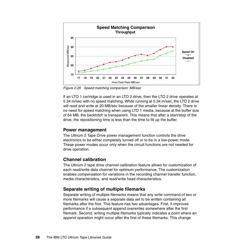
Figure 2-20 Speed matching comparison: MB/sec
If an LTO 1 cartridge is used in an LTO 2 drive, then the LTO 2 drive operates at 5.34 m/sec with no speed matching. While running at 5.34 m/sec, the LTO 2 drive will read and write at 20 MB/sec because of the smaller linear density. There is no need for speed matching when using LTO 1 media, because at the buffer size of 64 MB, the backhitch is transparent. This means that after a start/stop of the drive, the repositioning time is less than the time to fill up the buffer.
Power management The Ultrium 2 Tape Drive power management function controls the drive electronics to be either completely turned off or to be in a low-power mode. These power modes occur only when the circuit functions are not needed for drive operation.
Channel calibration The Ultrium 2 tape drive channel calibration feature allows for customization of each read/write data channel for optimum performance. The customization enables compensation for variations in the recording channel transfer function, media characteristics, and read/write head characteristics.
Separate writing of multiple filemarks Separate writing of multiple filemarks means that any write command of two or more filemarks will cause a separate data set to be written containing all filemarks after the first. This feature has two advantages. First, it improves performance if a subsequent append overwrites somewhere after the first filemark. Second, writing multiple filemarks typically indicates a point where an append operation might occur after the first of these filemarks. This change
17 18 19 20 21 22 23 24 25 26 27 28 29 30 31 32
Host Data Rate MB/sec
15
20
25
30
35
Mea
sure
d M
B/s
ec
Speed On
Disabled
Speed Matching ComparisonThroughput
38 The IBM LTO Ultrium Tape Libraries Guide

prevents having to rewrite datasets containing customer data and the first filemark if such an append occurs.
2.4.7 IBM Ultrium 1 and 2 compatibilityIBM Ultrium 2 tape drives (both standalone and in IBM Ultrium libraries) support both Ultrium 1 and Ultrium 2 cartridges. An Ultrium 1 cartridge in an Ultrium 2 drive will be written at the same 100 GB native capacity, but with improved performance (20 MB/s). Ultrium 1 drives cannot read or write an Ultrium 2 cartridge. If you put an Ultrium 2 cartridge in an Ultrium 1 drive, then you will get an “Unsupported Cartridge Format” failure. Figure 2-21 shows the compatibility.
Figure 2-21 IBM Ultrium 1 and 2 compatibility
2.4.8 Operating the Ultrium driveThe IBM subassembly itself has a simple status LED indicator, an unload push button, and a single-character display (see Figure 2-22 on page 40).
Ultrium 2 Cartridge
IBM Ultrium 2 Tape Drive
IBM Ultrium 1 Tape Drive
Ultrium 1 Cartridge 15 MB/s, 100 GB*
35 MB/s, 200 GB*
Ultrium 2 Logo
xxxxxxL2
xxxxxxL120 MB/s, 100 GB*
SCSI Inquiry:ULT3580-TD1
SCSI Inquiry:ULT3580-TD2
* Native sustained data rate, native capacity
Read/write Ultrium 1 format
Read/write Ultrium 2 format
Chapter 2. LTO technology 39

Figure 2-22 Front of subassembly showing operator panel indicators
The status LED uses color and lighting to indicate that:
� The tape is in motion for reading or writing.� The drive is rewinding, locating, or unloading the cartridge.� The drive is in maintenance mode.� A failure occurred and the drive or media requires service.� A microcode update is occurring.
The unload push button enables the operator to:
� Unload a cartridge� Enter maintenance mode and execute maintenance operations� Force a drive dump operation
The single-character display indicates errors and communicates messages, such as requests for cleaner tapes. It is also used by the operator for diagnostic and maintenance functions.
one-character
drive mouth
status LED
unload pushbutton
display
indicator
40 The IBM LTO Ultrium Tape Libraries Guide

2.4.9 ReliabilityThe IBM LTO Ultrium tape format differs from earlier IBM products. Reliability and availability features include:
� Data integrity
The drive performs a read after write, for verification. Incorrectly written data, such as the result of a tape defect, is automatically rewritten by the drive in a new location. Data rewritten as the result of media defects is not counted against the drive error performance.
The drive will never record incorrect data to the tape media without posting an error condition.
� Power loss
No recorded data is lost as a result of normal or abnormal power loss while the drive is reading or writing data. If power is lost while writing data, only the data block currently being written may be in error. Any previously written data will not be destroyed.
� Error correction
Data integrity features include two levels of error correction that can provide recovery from longitudinal media scratches.
� Integrated head cleaner
The head of the drive must be kept clean to prevent errors caused by contamination. During the load process, a brush integrated into the drive mechanism cleans the head before it is used with the tape. This keeps the head and media free of debris on a continuing basis and is expected to lead to less requirement for drive-cleaning operations.
� Surface control guiding
IBM's patented Surface Control Guiding Mechanism guides the tape along the tape path using the surface of the tape rather than the edges to control tape motion. Through grooved rollers (see Figure 2-23 on page 42), an air cushion builds between the tape and the rollers that keep it in the right position. This results in less tape damage (especially to the edges of the tape) and less debris from damaged edges that can accumulate in the head area, and helps minimize the chance of physical damage to the tape media.
Chapter 2. LTO technology 41

Figure 2-23 Surface control guiding
� Flat lap head
The flat head improves contact between the read and write recording elements and the tape, giving higher quality recording and readback of data.
Figure 2-24 Flat lap head
Surface control guiding and the flat lap head are designed to help minimize debris generated as the tape moves through its path, resulting in increased reliability in reading and writing data. This also potentially increases the life expectancy of the media by not using the edges of the tape to guide it over the read/write head. Historically, this also was a major source of debris on the tape path.
� Statistical Analysis and Reporting System
Statistical Analysis and Reporting System (SARS) is another IBM exclusive. Only IBM LTO drives provide this level of preventive diagnostic reporting. The Ultrium drive uses this reporting system to assist in isolating failures between media and hardware. SARS uses the cartridge performance history saved in the CM module and the drive performance history kept in the drive flash
42 The IBM LTO Ultrium Tape Libraries Guide

EEPROM to determine the most likely cause of failure. It then can cause the drive to request a cleaner tape, to mark the media as degraded, and to indicate that the hardware has degraded. SARS reports the results of its analysis in the form of Tape Alert if needed (see Figure 2-25).
Figure 2-25 Statistical Analysis and Reporting System
2.4.10 Cleaning the driveIn addition to the integrated head-cleaning mechanism, IBM recommends that the drive be cleaned regularly, with automatic cleaning enabled where supported in the libraries. Regular cleaning avoids drive shutdowns because of improper maintenance or contaminants that cause the drive to fail.
In the unusual event that the drive head becomes clogged, it may be necessary to use the specially labeled IBM LTO Ultrium cleaning cartridge supplied with each Ultrium tape drive product. The cleaning cartridge is good for 50 cleaning operations. If cleaning proves necessary, the LTO-CM memory in a cleaning cartridge is used to track the number of times that the cartridge has been used. After the cartridge has been used 50 times, the drive will mark the cleaning cartridge as expired. This also protects you from accidentally reinserting a cleaning cartridge that has been used 50 times.
Combines Cartridge/Drive Histories; Checks and Updates Each Mount/Dismount to Continuously Monitor Reliability Data to Support Data Integrity
Predictive Failure Analysis Firmware
Hardware Hardware SARSSARS
Host/Server
Volume Volume SARSSARS
Log Sense Page
(0x2E) VPD HistorySummaryMount Queue
DRAMCurrent
Mount
Usage Info AreaSummaryMount Queue
Mechanism AreaSummaryMount Queue
Tape Alert
Tape Cartridge Memory (CM)
Tape Drive EEPROM
Chapter 2. LTO technology 43

2.5 The IBM LTO Ultrium family of tapes and librariesThe IBM Ultrium family of tapes and libraries (pictured in Figure 2-26) comprises five different product offerings, ranging from a stand-alone unit to a highly scalable automated library.
.
Figure 2-26 The IBM Ultrium family of tapes and libraries
Note: The use of cleaning cartridges is not necessary (and is discouraged) for normal operation of Ultrium tape drives. See 3580 Ultrium Tape Drive Setup, Operator, and Service Guide, GA32-0415, for information about drive cleaning.
44 The IBM LTO Ultrium Tape Libraries Guide

They are all based on a common tape drive subassembly packaged in different robotic and stand-alone environments.
� The IBM TotalStorage Ultrium Tape Drive 3580 is a stand-alone desktop single-drive unit without autoloader. Tapes are mounted manually one at a time.
� The IBM TotalStorage Ultrium Tape Autoloader 3581 is also a single-drive unit, but it has a seven-cartridge autoloader within the device. It is a stand-alone desktop unit; however, optional additional hardware is available for installation in a standard 19-inch rack.
� The IBM TotalStorage Ultrium Tape Library 3582 is a small robotic library, accommodating one to two drives and providing space for up to 23 Ultrium cartridges. The IBM 3582 may be stand-alone or, with an optional feature, housed in a rack.
� The IBM TotalStorage Ultrium Scalable Tape Library 3583 is a small robotic library, accommodating from one to six drives and providing space for up to 72 Ultrium cartridges. The IBM 3583 may be standalone or, with an optional feature, housed in a rack.
� The IBM TotalStorage UltraScalable Tape Library 3584 is a larger modular library with the potential to house a maximum of 192 tape drives in as many as 16 frames. There is a trade-off between cartridge capacity and installed drives, so that a fully-configured library with 192 drives and a 10-cartridge I/O station has a cartridge capacity of 6167; with a minimal drive configuration the cartridge capacity can reach a maximum of 6881.
Storage and tape management for the IBM LTO Ultrium family is provided by software such as IBM Tivoli Storage Manager and other similar software offerings.
These products, while all part of the same family, are distinct offerings. The drive and cartridge technology and formats are the same, and the cartridges are interchangeable between the libraries, as dictated by the LTO format standards. However, the machine types (for example, 3583 and 3584) are not upgradeable from one to another, nor can the Ultrium drives be exchanged between different libraries. Thus, if you purchase an IBM 3583 with six drives and later on install an IBM 3584, you cannot transfer the Ultrium drives from the 3583 to the 3584.
Detailed descriptions of these products can be found in Chapter 4, “IBM TotalStorage Ultrium Tape Drive 3580” on page 79, through Chapter 8, “IBM TotalStorage UltraScalable Tape Library 3584” on page 159.
The IBM LTO family of products is sold directly through IBM and its Business Partners.
Chapter 2. LTO technology 45

2.6 Multi-path architectureThis patented multi-path architecture was introduced with the IBM Magstar MP 3575 library. It provides a way to share a tape library between a number of servers without the need to implement application software to control and serialize tape drives and media. It is also implemented in the IBM 3582, 3583, and 3584 libraries.
Multi-path architecture is an IBM unique feature. The IBM 3582, 3583, and 3584 LTO libraries feature the second generation of the architecture introduced with the Magstar MP 3575 library. It uses the SCSI-3 Move Media command set that is featured in midrange and open libraries. The key benefit is that multi-path architecture removes the need for a dedicated server plus middleware to control the use of a library by many different hosts utilizing different operating systems, as each drive has its own path to the control unit.
Conventional tape libraries use a dedicated host port to communicate to the library, such as to send mount request commands. IBM LTO tape libraries use the same path to communicate with both the drives and the library controller, as shown in Figure 2-27. This is not one dedicated path, but it may be any path to any tape drive.
Figure 2-27 Conventional tape library vs. multi-path architecture
For conventional tape libraries, the control path is a single point of failure. In contrast, the IBM LTO tape libraries offer as many control paths as there are drives installed in the library, so in the event of individual control path failure you can communicate with your library over different, redundant control paths. As shown in Figure 2-28 on page 47, if one path to a drive is broken because of a
Library Controller
Host System
Conventional Tape Library With Dedicated Host Port
IBM 3584 Tape Library With LUN-1 Multi-Path Architecture
Drive ManagementData Path
Single Control Path
Drive
Drive
Drive
DriveIBM
Library Controller
Host System
Data and Control Paths
Drive Management and Multiple Control Paths
Drive
Drive
Drive
DriveI BM
46 The IBM LTO Ultrium Tape Libraries Guide
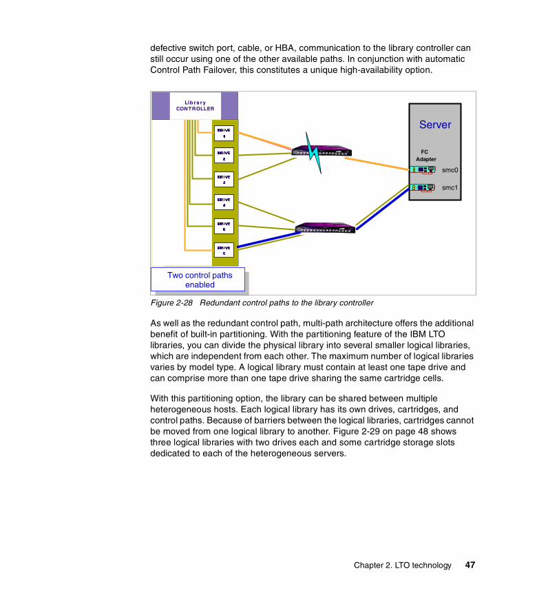
defective switch port, cable, or HBA, communication to the library controller can still occur using one of the other available paths. In conjunction with automatic Control Path Failover, this constitutes a unique high-availability option.
Figure 2-28 Redundant control paths to the library controller
As well as the redundant control path, multi-path architecture offers the additional benefit of built-in partitioning. With the partitioning feature of the IBM LTO libraries, you can divide the physical library into several smaller logical libraries, which are independent from each other. The maximum number of logical libraries varies by model type. A logical library must contain at least one tape drive and can comprise more than one tape drive sharing the same cartridge cells.
With this partitioning option, the library can be shared between multiple heterogeneous hosts. Each logical library has its own drives, cartridges, and control paths. Because of barriers between the logical libraries, cartridges cannot be moved from one logical library to another. Figure 2-29 on page 48 shows three logical libraries with two drives each and some cartridge storage slots dedicated to each of the heterogeneous servers.
DRIVE
1
DRIVE
2
Lib ra ry CONTROLLER
DRIVE
3
DRIVE
4
DRIVE
5
DRIVE
6
Two control paths enabled
FC Adapter
Server
smc0
smc1
Chapter 2. LTO technology 47

Figure 2-29 IBM LTO tape library partitioned into three logical libraries
Up to 12 Hosts per
Frame
DRIVE
1
DRIVE
2
Logical Library 1
Logical Library 2
Logical Library 3
Library CONTROLLER
DRIVE
3
DRIVE
4
DRIVE
5
DRIVE
6
to Host 1
to Host 2
to Host 3
iSeriesApp A
Windows App B
pSeries App C
Multiple hosts 'owning' separate logical library slots and drives
48 The IBM LTO Ultrium Tape Libraries Guide

Chapter 3. Tape storage market direction
Tape systems traditionally have been associated with the mainframe computer market, because they have represented an essential element in mainframe systems architectures since the early 1950s as a cost-effective way to store large amounts of data. The mid-range and client/server computer market has, in contrast, made very limited use of tape technology until quite recently.
Over the past few years, however, the growth in the demand for data storage and reliable backup and archiving solutions has greatly increased the need to provide manageable and cost-effective tape library products. The value of using tape for backup purposes hasonly gradually become obvious and important in these environments.
In this chapter, we will review the technologies, formats, and standards that you will see for tape products in today’s market. We discuss a number of products from non-IBM vendors and, although we have reviewed the material carefully, we would remind you that the vendors of those products are the definitive source of information.
3
© Copyright IBM Corp. 2000, 2003. All rights reserved. 49

3.1 Current tape products and technologiesTwo basic tape technologies have been utilized. Until the middle of the 1980s, all computer tape systems utilized linear recording technology, a technology that uses a stationary head writing data in a longitudinal way (see Figure 3-3 on page 54 for an example of longitudinal technology).
In the middle of the 1980s, helical tape technology (which had been developed for video applications) became available for computer data storage, a technology that uses heads rotating on a drum and writing data in an angle. Helical tape systems found natural applications in backing up magnetic disk systems where their cost advantages substantially outweighed their operational disadvantages (see Figure 3-4 on page 55 for an example of helical-scan technology).
3.1.1 Helical versus longitudinalThe first computer tape systems used linear recording technology. This technology provides excellent data integrity, rapid access to data records, and reasonable storage density.
The first implementation of linear recording technology used magnetic tapes on open reels. Later, the tape was protected inside cartridges, using one or two reels. Linear technology drives write each data track on the entire length of the tape. Data is first written onto a track along the entire length of the tape, and when the end is reached, the heads are repositioned to record a new track again, along the entire length of the tape, now travelling in the opposite direction. This continues back and forth until the tape is full. On linear drives, the tape is guided around a static head.
On helical scan systems, by contrast, the tape is wrapped around a rotating drum containing read/write heads. Due to the more complicated path, mechanical stress is placed on the tape. When contrasted with linear tape systems, helical tape systems have higher density (and, therefore, lower media cost), but lower data transfer rates (due to the smaller number of active read/write heads), less effective access to random data records, increased maintenance requirements, and reduced data integrity.
Both linear and helical tape systems have advanced substantially over the past decade. Linear systems have improved significantly in the areas of storage density (and, therefore, cost), and operational convenience (with a variety of removable cartridge systems such as 3590, QIC, DLT, and now LTO replacing reel-to-reel systems). Helical systems have improved in the areas of transfer rate and data integrity with the implementation of both channel and error correction coding technologies.
50 The IBM LTO Ultrium Tape Libraries Guide

Over the past few years, one of the most significant advances in tape technology for computer applications has been the maturation of serpentine linear recording systems which, for the first time, has permitted linear recording systems to provide recording density that is comparable with that of helical systems. The first commercially successful serpentine linear tape system for professional applications was DLT. Another important improvement is the use of servo tracks, first introduced by IBM on the Magstar 3590 tape. Servo tracks on the tape cartridge are recorded at the time of manufacture. These tracks enable the tape drive to position the read/write head accurately with respect to the media while the tape is in motion.
Most linear media is manufactured using metal particle (MP) technology. As with most tape products, metal particle media comprises several layers: a substrate that provides the base for other layers, the magnetic layer where data is stored, and a back coat that controls the media’s frictional characteristics.
The most advanced implementations of 8 mm format (Mammoth and AIT) use AME (Advanced Metal Evaporative) media. The AME magnetic layer is 100% cobalt and is a much thinner, pure magnetic layer that doesn’t contain any binders or lubricants. These qualities give AME tapes greater potential data density so that more information can be stored on less tape surface.
Future generations of linear tape media (including LTO) will use the same AME magnetic layer technology, offering increased data densities.
We felt that the fundamental difference between linear recording and helical scan technologies is so important that it would be worthwhile to summarize all of the available current technologies (see Table 3-1).
Table 3-1 Tape technology overview
Name Recording technology
Media width Type
1/2-inch reels linear 1/2 inch single hub
QIC linear 1/4 in and 8 mm dual hub
DAT/4 mm helical-scan 4 mm dual hub
DDS helical-scan all 4 mm dual hub
8 mm helical-scan 8 mm dual hub
Mammoth helical-scan 8 mm dual hub
AIT helical-scan 8 mm dual hub
Ecrix VXA helical-scan 8 mm dual hub
Chapter 3. Tape storage market direction 51
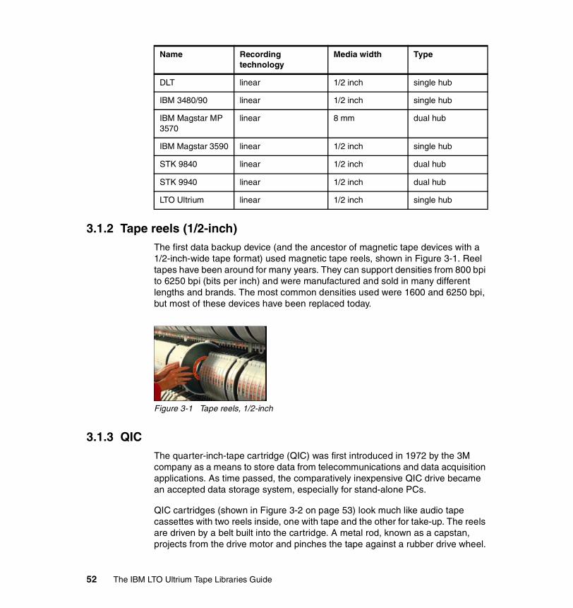
3.1.2 Tape reels (1/2-inch)The first data backup device (and the ancestor of magnetic tape devices with a 1/2-inch-wide tape format) used magnetic tape reels, shown in Figure 3-1. Reel tapes have been around for many years. They can support densities from 800 bpi to 6250 bpi (bits per inch) and were manufactured and sold in many different lengths and brands. The most common densities used were 1600 and 6250 bpi, but most of these devices have been replaced today.
Figure 3-1 Tape reels, 1/2-inch
3.1.3 QICThe quarter-inch-tape cartridge (QIC) was first introduced in 1972 by the 3M company as a means to store data from telecommunications and data acquisition applications. As time passed, the comparatively inexpensive QIC drive became an accepted data storage system, especially for stand-alone PCs.
QIC cartridges (shown in Figure 3-2 on page 53) look much like audio tape cassettes with two reels inside, one with tape and the other for take-up. The reels are driven by a belt built into the cartridge. A metal rod, known as a capstan, projects from the drive motor and pinches the tape against a rubber drive wheel.
DLT linear 1/2 inch single hub
IBM 3480/90 linear 1/2 inch single hub
IBM Magstar MP 3570
linear 8 mm dual hub
IBM Magstar 3590 linear 1/2 inch single hub
STK 9840 linear 1/2 inch dual hub
STK 9940 linear 1/2 inch dual hub
LTO Ultrium linear 1/2 inch single hub
Name Recording technology
Media width Type
52 The IBM LTO Ultrium Tape Libraries Guide

Figure 3-2 QIC cartridge
The QIC format employs a linear (or longitudinal) recording technique in which data is written to parallel tracks that run along the length of the tape. The number of tracks is the principle determinant of capacity. The cartridges come in two varieties, DC600 cartridge and DC2000 mini cartridge, the latter being the more popular. The encoding method used is either MFM (Modified Frequency Modulation) or RLL (Run Length Limited), and is similar to the way a hard drive encodes data.
When a backup is started, directory information from the file allocation table is loaded into a memory buffer in the system's RAM, along with the appropriate files. Both sets of data are sent to the tape drive controller, each file being prefaced by a header containing the directory information. If the controller has built-in error correction, an error correction code (ECC) is appended to the data in the controller. Otherwise, the software adds the code before sending the data to the controller.
The controller contains its own buffer. Once the backup data containing the ECC is in this buffer, the backup software is free to load more data into system memory. The drive's controller then sends the data as required to the tape drive mechanism.
QIC uses a linear read/write head similar to those found in domestic cassette recorders (Figure 3-3 on page 54). The head contains a single write head flanked on either side by a read head. This allows the tape drive to verify data just written when the tape is running in either direction. If the data just written is verified by the read head, the buffer is flushed out and new data is acquired from the system memory.
Chapter 3. Tape storage market direction 53
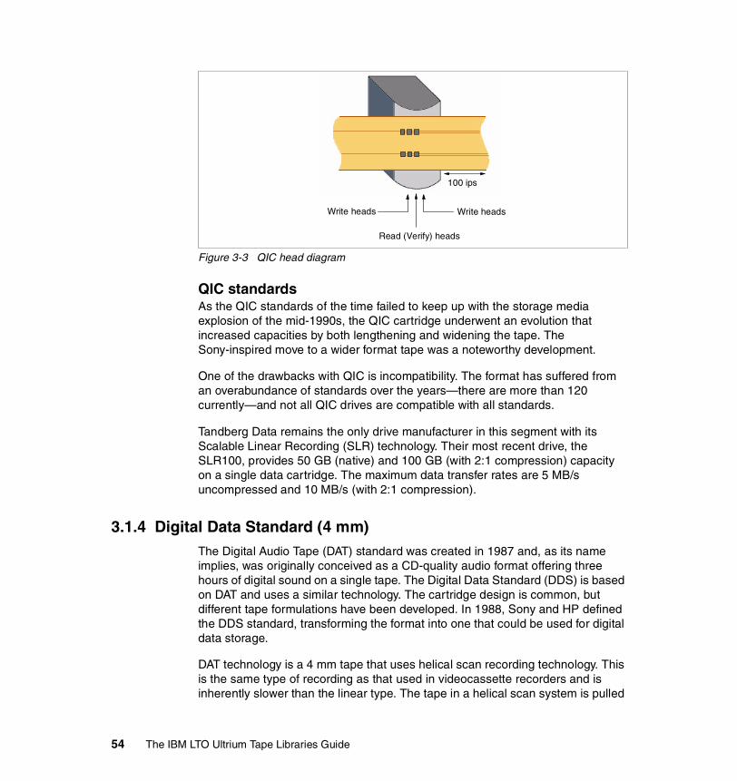
Figure 3-3 QIC head diagram
QIC standardsAs the QIC standards of the time failed to keep up with the storage media explosion of the mid-1990s, the QIC cartridge underwent an evolution that increased capacities by both lengthening and widening the tape. The Sony-inspired move to a wider format tape was a noteworthy development.
One of the drawbacks with QIC is incompatibility. The format has suffered from an overabundance of standards over the years—there are more than 120 currently—and not all QIC drives are compatible with all standards.
Tandberg Data remains the only drive manufacturer in this segment with its Scalable Linear Recording (SLR) technology. Their most recent drive, the SLR100, provides 50 GB (native) and 100 GB (with 2:1 compression) capacity on a single data cartridge. The maximum data transfer rates are 5 MB/s uncompressed and 10 MB/s (with 2:1 compression).
3.1.4 Digital Data Standard (4 mm)The Digital Audio Tape (DAT) standard was created in 1987 and, as its name implies, was originally conceived as a CD-quality audio format offering three hours of digital sound on a single tape. The Digital Data Standard (DDS) is based on DAT and uses a similar technology. The cartridge design is common, but different tape formulations have been developed. In 1988, Sony and HP defined the DDS standard, transforming the format into one that could be used for digital data storage.
DAT technology is a 4 mm tape that uses helical scan recording technology. This is the same type of recording as that used in videocassette recorders and is inherently slower than the linear type. The tape in a helical scan system is pulled
100 ips
Write headsWrite heads
Read (Verify) heads
54 The IBM LTO Ultrium Tape Libraries Guide

from a two-reel cartridge and wrapped around a cylindrical drum containing two read heads and two write heads, arranged alternately. The read heads verify the data written by the write heads. The cylinder head is tilted slightly in relation to the tape and spins at 2,000 revolutions per minute. The tape moves in the opposite direction to the cylindrical spin, at less than one inch per second, but because it is recording more than one line at a time it has an effective speed of 150 inches per second (refer to Figure 3-4).
Short diagonal tracks, about eight times longer than the width are written across the width of the tape. These each contain about 128KB of data and an error correction code.
Figure 3-4 Helical-scan recording diagram
A read head verifies the data. If errors are present the data is rewritten; otherwise the controller buffer is flushed ready for the next segment. The second write head writes data at a 40-degree angle to the first one.
Even though the first and second writes overlap, they are magnetically encoded with different polarities so they are only read by the correct read head. The “criss-cross” pattern packs more data onto the tape, enabling helical scan systems to achieve very high data densities. A directory of files is stored in a partition at the front of the tape.
Just as with linear recording, the performance would be greatly improved if additional read/write heads were added, but this is difficult with helical scan devices, because of the design of the rotating head. The fact that the heads may only be added in pairs makes it difficult to fit the wiring inside a single cylinder, and this limits the potential performance of helical scan devices. Because of the
2000 rpm
5 degrees
Write B
Verify A
Verify B
Write A
.5 ips
Data recorded inangled stripesacross the tape
2 Write and2 Verify headsspaced at90 degrees
Chapter 3. Tape storage market direction 55
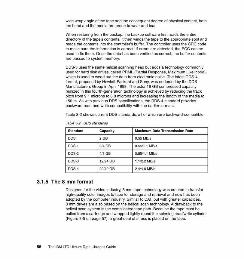
wide wrap angle of the tape and the consequent degree of physical contact, both the head and the media are prone to wear and tear.
When restoring from the backup, the backup software first reads the entire directory of the tape’s contents. It then winds the tape to the appropriate spot and reads the contents into the controller’s buffer. The controller uses the CRC code to make sure the information is correct. If errors are detected, the ECC can be used to fix them. Once the data has been verified as correct, the buffer contents are passed to system memory.
DDS-3 uses the same helical scanning head but adds a technology commonly used for hard disk drives, called PRML (Partial Response, Maximum Likelihood), which is used to weed out the data from electronic noise. The latest DDS-4 format, proposed by Hewlett-Packard and Sony, was endorsed by the DDS Manufacturers Group in April 1998. The extra 16 GB compressed capacity realized in this fourth-generation technology is achieved by reducing the track pitch from 9.1 microns to 6.8 microns and increasing the length of the media to 150 m. As with previous DDS specifications, the DDS-4 standard provides backward read and write compatibility with the earlier formats.
Table 3-2 shows current DDS standards, all of which are backward-compatible.
Table 3-2 DDS standards
3.1.5 The 8 mm formatDesigned for the video industry, 8 mm tape technology was created to transfer high-quality color images to tape for storage and retrieval and now has been adopted by the computer industry. Similar to DAT, but with greater capacities, 8 mm drives are also based on the helical scan technology. A drawback to the helical scan system is the complicated tape path. Because the tape must be pulled from a cartridge and wrapped tightly round the spinning read/write cylinder (Figure 3-5 on page 57), a great deal of stress is placed on the tape.
Standard Capacity Maximum Data Transmission Rate
DDS 2 GB 0.55 MB/s
DDS-1 2/4 GB 0.55/1.1 MB/s
DDS-2 4/8 GB 0.55/1.1 MB/s
DDS-3 12/24 GB 1.1/2.2 MB/s
DDS-4 20/40 GB 2.4/4.8 MB/s
56 The IBM LTO Ultrium Tape Libraries Guide
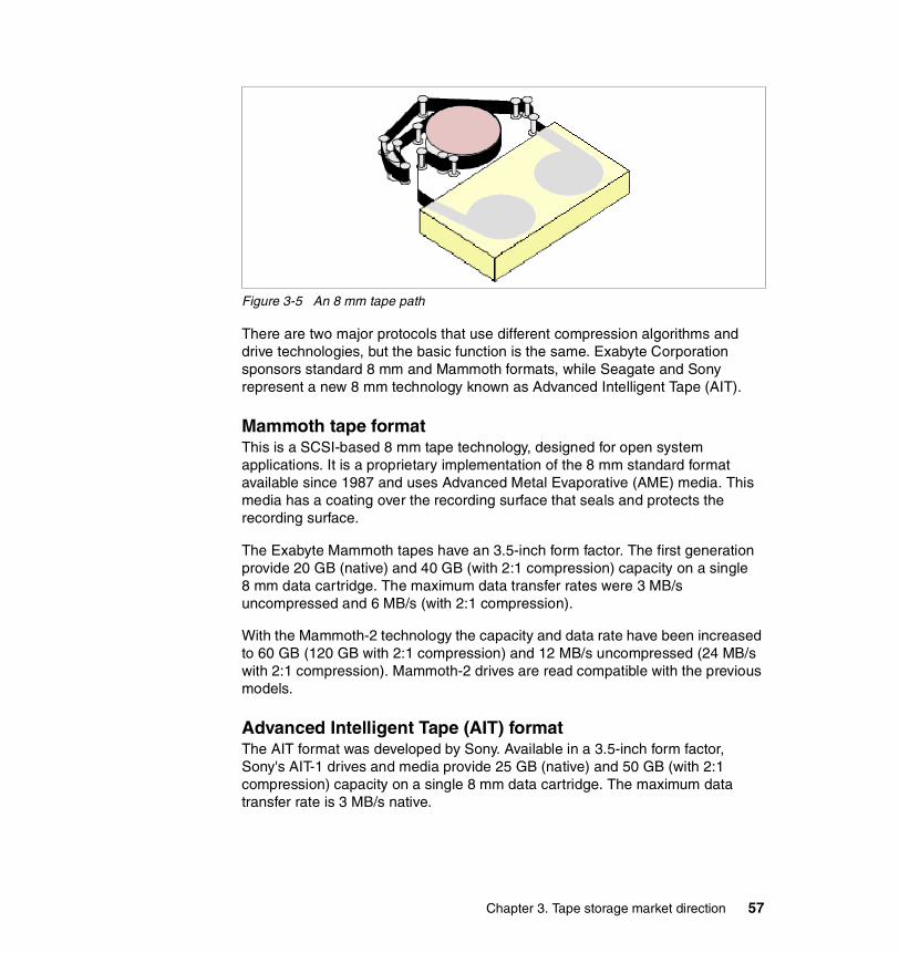
Figure 3-5 An 8 mm tape path
There are two major protocols that use different compression algorithms and drive technologies, but the basic function is the same. Exabyte Corporation sponsors standard 8 mm and Mammoth formats, while Seagate and Sony represent a new 8 mm technology known as Advanced Intelligent Tape (AIT).
Mammoth tape formatThis is a SCSI-based 8 mm tape technology, designed for open system applications. It is a proprietary implementation of the 8 mm standard format available since 1987 and uses Advanced Metal Evaporative (AME) media. This media has a coating over the recording surface that seals and protects the recording surface.
The Exabyte Mammoth tapes have an 3.5-inch form factor. The first generation provide 20 GB (native) and 40 GB (with 2:1 compression) capacity on a single 8 mm data cartridge. The maximum data transfer rates were 3 MB/s uncompressed and 6 MB/s (with 2:1 compression).
With the Mammoth-2 technology the capacity and data rate have been increased to 60 GB (120 GB with 2:1 compression) and 12 MB/s uncompressed (24 MB/s with 2:1 compression). Mammoth-2 drives are read compatible with the previous models.
Advanced Intelligent Tape (AIT) format The AIT format was developed by Sony. Available in a 3.5-inch form factor, Sony's AIT-1 drives and media provide 25 GB (native) and 50 GB (with 2:1 compression) capacity on a single 8 mm data cartridge. The maximum data transfer rate is 3 MB/s native.
Chapter 3. Tape storage market direction 57

With the AIT-2 technology made available in 1999, the capacity and data rate have been increased to 50 GB (100 GB with 2:1 compression) and 6 MB/s native. AIT-2 drives are backward-compatible with the AIT-1models.
Sony's latest AIT-3 format, made available in 2001, doubles the capacity and performance of the prior generation to 100 GB (200 GB with 2:1 compression) and 12 MB/s native. AIT-3 drives are backward-compatible with the AIT-2 and AIT-1 models.
AIT drives feature an Auto Tracking Following (ATF) system, which provides a closed-loop, self-adjusting path for tape tracking. This servo tracking system adjusts for tape flutter, allowing data tracks to be written much closer together for high-density recording. AIT provides Fast/Wide SCSI technology with data transfer rates of up to 12 MB/s (native), 24.0 MB/s (with 2:1 compression). AIT uses the Adaptive Lossless Data Compression technology (ALDC) compression algorithm. The 8 mm standard has various drive generations, all of which are backward-compatible, shown in Table 3-3.
Table 3-3 Standards for 8 mm
3.1.6 Digital Linear Tape (DLT) DLT drives appeared in 1985 when Digital Equipment Corporation needed a backup system for their MicroVAX systems.
The system uses a square cartridge that contains tape media but no take-up reel. The take-up reel was built into the drive itself. This design eliminated the additional space typically associated with cassette and cartridge drives such as
Standard Capacity Maximum Data Transmission Rate(compressed)
Standard 8 mm 3.5/7 GB 0.53 MB/s
Standard 8 mm 5/10 GB 1 MB/s
Standard 8 mm 7/14 GB 1 MB/s
Standard 8 mm 7/14 GB 2 MB/s
Mammoth 20/40 GB 6 MB/s
Mammoth-2 60/120 GB 24 MB/s
AIT-1 25/50 GB 6 MB/s
AIT-2 50/100 GB 12 MB/s
AIT-3 100/200 GB 24 MB/s
58 The IBM LTO Ultrium Tape Libraries Guide
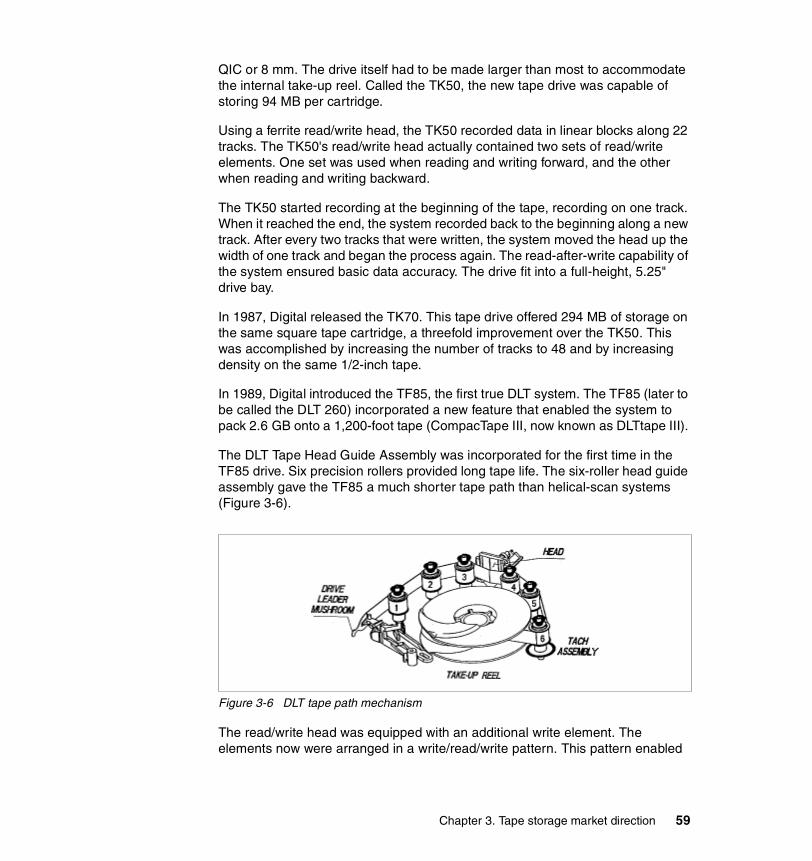
QIC or 8 mm. The drive itself had to be made larger than most to accommodate the internal take-up reel. Called the TK50, the new tape drive was capable of storing 94 MB per cartridge.
Using a ferrite read/write head, the TK50 recorded data in linear blocks along 22 tracks. The TK50's read/write head actually contained two sets of read/write elements. One set was used when reading and writing forward, and the other when reading and writing backward.
The TK50 started recording at the beginning of the tape, recording on one track. When it reached the end, the system recorded back to the beginning along a new track. After every two tracks that were written, the system moved the head up the width of one track and began the process again. The read-after-write capability of the system ensured basic data accuracy. The drive fit into a full-height, 5.25" drive bay.
In 1987, Digital released the TK70. This tape drive offered 294 MB of storage on the same square tape cartridge, a threefold improvement over the TK50. This was accomplished by increasing the number of tracks to 48 and by increasing density on the same 1/2-inch tape.
In 1989, Digital introduced the TF85, the first true DLT system. The TF85 (later to be called the DLT 260) incorporated a new feature that enabled the system to pack 2.6 GB onto a 1,200-foot tape (CompacTape III, now known as DLTtape III).
The DLT Tape Head Guide Assembly was incorporated for the first time in the TF85 drive. Six precision rollers provided long tape life. The six-roller head guide assembly gave the TF85 a much shorter tape path than helical-scan systems (Figure 3-6).
Figure 3-6 DLT tape path mechanism
The read/write head was equipped with an additional write element. The elements now were arranged in a write/read/write pattern. This pattern enabled
Chapter 3. Tape storage market direction 59
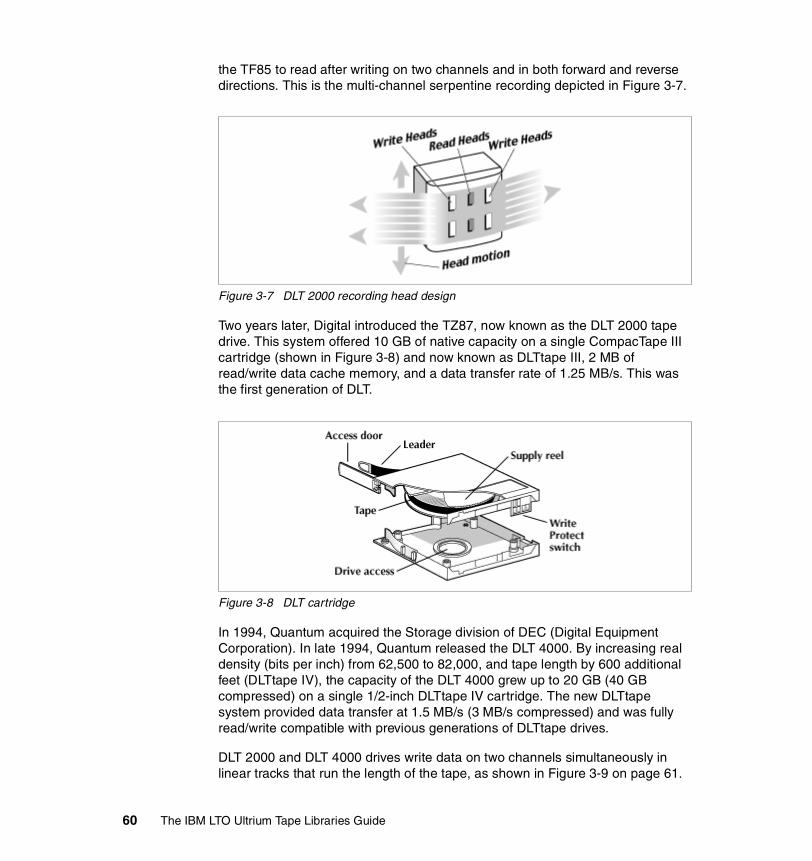
the TF85 to read after writing on two channels and in both forward and reverse directions. This is the multi-channel serpentine recording depicted in Figure 3-7.
Figure 3-7 DLT 2000 recording head design
Two years later, Digital introduced the TZ87, now known as the DLT 2000 tape drive. This system offered 10 GB of native capacity on a single CompacTape III cartridge (shown in Figure 3-8) and now known as DLTtape III, 2 MB of read/write data cache memory, and a data transfer rate of 1.25 MB/s. This was the first generation of DLT.
Figure 3-8 DLT cartridge
In 1994, Quantum acquired the Storage division of DEC (Digital Equipment Corporation). In late 1994, Quantum released the DLT 4000. By increasing real density (bits per inch) from 62,500 to 82,000, and tape length by 600 additional feet (DLTtape IV), the capacity of the DLT 4000 grew up to 20 GB (40 GB compressed) on a single 1/2-inch DLTtape IV cartridge. The new DLTtape system provided data transfer at 1.5 MB/s (3 MB/s compressed) and was fully read/write compatible with previous generations of DLTtape drives.
DLT 2000 and DLT 4000 drives write data on two channels simultaneously in linear tracks that run the length of the tape, as shown in Figure 3-9 on page 61.
60 The IBM LTO Ultrium Tape Libraries Guide

Figure 3-9 DLT 2000/4000 linear recording format
The DLT 7000 appeared in 1996. This drive offered a total storage capacity of 35 GB native, 70 GB compressed on the 1,800 foot DLTtape IV cartridge. The DLT 7000 incorporated a 4-channel head that gives the drive a transfer rate of 5 MB/s of data in native mode (Figure 3-10).
Figure 3-10 DLT 7000/8000 tape head
Quantum’s latest DLT product is their DLT 8000 drive. This tape drive features a native transfer rate of up to 6 MB/s, with a native capacity of 40 GB. The DLT 7000/8000 drives incorporate the Symmetric Phase Recording technology that writes data in an angled pattern (Figure 3-11).
Figure 3-11 Symmetric Phase Recording technology
The DLT standard has various generations of tape drive, all of which are backward-compatible. We have summarized the specifications in Table 3-4 on page 62.
Chapter 3. Tape storage market direction 61

Table 3-4 DLT drive standards
3.1.7 SuperDLT (SDLT)SuperDLT (SDLT) is a new format specification designed by Quantum Corporation as an evolution of the DLT standard. It uses Laser Guided Magnetic Recording (LGMR) technology. This technology includes the Pivoting Optical Servo (POS). This optically assisted servo system is implemented on the unused reverse side of the media and uses a laser to read the servo guide. SDLT uses 100% of the media for data recording.
SDLT uses Advanced Metal Powder (AMP) media containing embedded information for the Pivoting Optical Servo system.
The recording mechanism is made of Magneto-Resistive Cluster (MRC) heads, a cluster of small magneto-resistive tape heads.
The first SDLT drive, the SDLT 220, was introduced in late 2000. It provides a capacity of 110 GB (native) and 220 GB (with 2:1 compression). The native data transfer rate is 11 MB/sec. This first drive was not backward-read-compatible with earlier models. In 2001 Quantum released a version of the SDLT 220 drive that was backward-read-compatible with the DLTtape IV cartridge.
Quantum's latest SDLT 320 drive came available in 2002. It increased the native capacity to 160 GB (320 GB with 2:1 compression) and the native transfer rate to 16 MB/sec (32 MB/sec with 2:1 compression). The SDLT 320 is backward read compatible with DLTtape IV cartridges and uses Super DLTtape I media.
DLT drive generation Capacity Maximum data transmission rate
DLT2000 10/20 GB 1.25 MB/s
DLT2000XT 15/30 GB 1.25 MB/s
DLT4000 20/40 GB 1.5 MB/s
DLT7000 35/70 GB 5 MB/s
DLT8000 40/80 GB 6 MB/s
62 The IBM LTO Ultrium Tape Libraries Guide
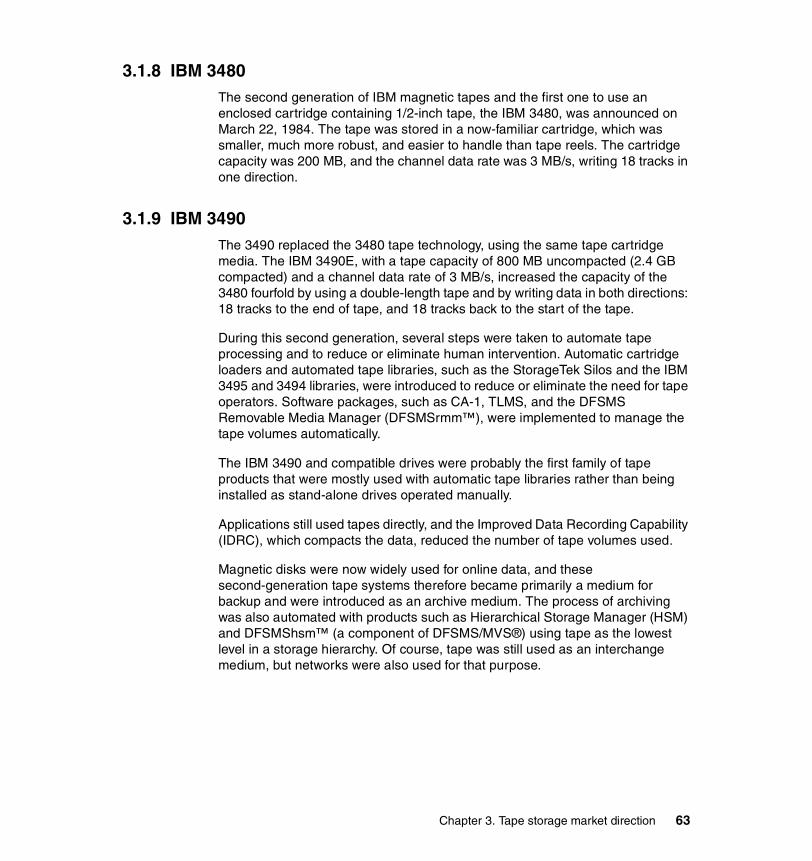
3.1.8 IBM 3480The second generation of IBM magnetic tapes and the first one to use an enclosed cartridge containing 1/2-inch tape, the IBM 3480, was announced on March 22, 1984. The tape was stored in a now-familiar cartridge, which was smaller, much more robust, and easier to handle than tape reels. The cartridge capacity was 200 MB, and the channel data rate was 3 MB/s, writing 18 tracks in one direction.
3.1.9 IBM 3490The 3490 replaced the 3480 tape technology, using the same tape cartridge media. The IBM 3490E, with a tape capacity of 800 MB uncompacted (2.4 GB compacted) and a channel data rate of 3 MB/s, increased the capacity of the 3480 fourfold by using a double-length tape and by writing data in both directions: 18 tracks to the end of tape, and 18 tracks back to the start of the tape.
During this second generation, several steps were taken to automate tape processing and to reduce or eliminate human intervention. Automatic cartridge loaders and automated tape libraries, such as the StorageTek Silos and the IBM 3495 and 3494 libraries, were introduced to reduce or eliminate the need for tape operators. Software packages, such as CA-1, TLMS, and the DFSMS Removable Media Manager (DFSMSrmm™), were implemented to manage the tape volumes automatically.
The IBM 3490 and compatible drives were probably the first family of tape products that were mostly used with automatic tape libraries rather than being installed as stand-alone drives operated manually.
Applications still used tapes directly, and the Improved Data Recording Capability (IDRC), which compacts the data, reduced the number of tape volumes used.
Magnetic disks were now widely used for online data, and these second-generation tape systems therefore became primarily a medium for backup and were introduced as an archive medium. The process of archiving was also automated with products such as Hierarchical Storage Manager (HSM) and DFSMShsm™ (a component of DFSMS/MVS®) using tape as the lowest level in a storage hierarchy. Of course, tape was still used as an interchange medium, but networks were also used for that purpose.
Chapter 3. Tape storage market direction 63
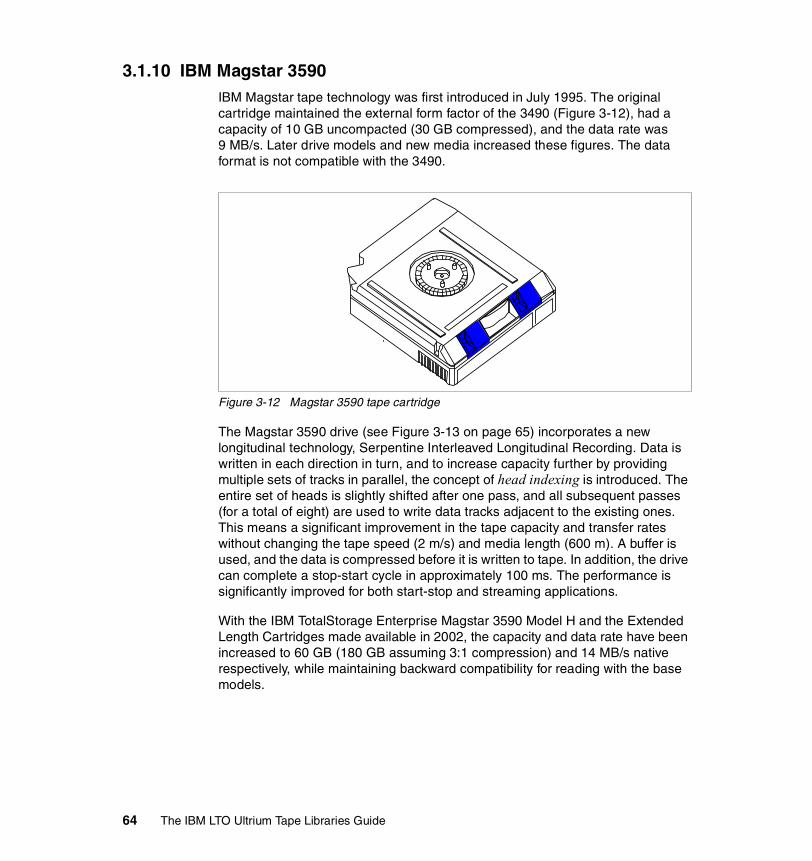
3.1.10 IBM Magstar 3590IBM Magstar tape technology was first introduced in July 1995. The original cartridge maintained the external form factor of the 3490 (Figure 3-12), had a capacity of 10 GB uncompacted (30 GB compressed), and the data rate was 9 MB/s. Later drive models and new media increased these figures. The data format is not compatible with the 3490.
Figure 3-12 Magstar 3590 tape cartridge
The Magstar 3590 drive (see Figure 3-13 on page 65) incorporates a new longitudinal technology, Serpentine Interleaved Longitudinal Recording. Data is written in each direction in turn, and to increase capacity further by providing multiple sets of tracks in parallel, the concept of head indexing is introduced. The entire set of heads is slightly shifted after one pass, and all subsequent passes (for a total of eight) are used to write data tracks adjacent to the existing ones. This means a significant improvement in the tape capacity and transfer rates without changing the tape speed (2 m/s) and media length (600 m). A buffer is used, and the data is compressed before it is written to tape. In addition, the drive can complete a stop-start cycle in approximately 100 ms. The performance is significantly improved for both start-stop and streaming applications.
With the IBM TotalStorage Enterprise Magstar 3590 Model H and the Extended Length Cartridges made available in 2002, the capacity and data rate have been increased to 60 GB (180 GB assuming 3:1 compression) and 14 MB/s native respectively, while maintaining backward compatibility for reading with the base models.
64 The IBM LTO Ultrium Tape Libraries Guide
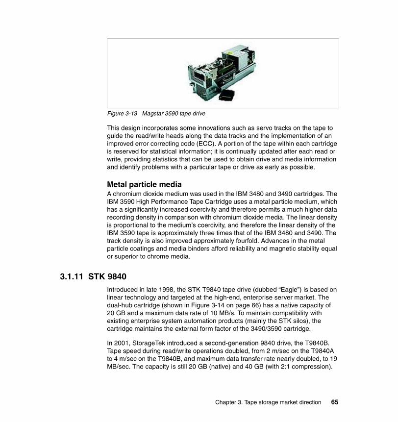
Figure 3-13 Magstar 3590 tape drive
This design incorporates some innovations such as servo tracks on the tape to guide the read/write heads along the data tracks and the implementation of an improved error correcting code (ECC). A portion of the tape within each cartridge is reserved for statistical information; it is continually updated after each read or write, providing statistics that can be used to obtain drive and media information and identify problems with a particular tape or drive as early as possible.
Metal particle mediaA chromium dioxide medium was used in the IBM 3480 and 3490 cartridges. The IBM 3590 High Performance Tape Cartridge uses a metal particle medium, which has a significantly increased coercivity and therefore permits a much higher data recording density in comparison with chromium dioxide media. The linear density is proportional to the medium’s coercivity, and therefore the linear density of the IBM 3590 tape is approximately three times that of the IBM 3480 and 3490. The track density is also improved approximately fourfold. Advances in the metal particle coatings and media binders afford reliability and magnetic stability equal or superior to chrome media.
3.1.11 STK 9840Introduced in late 1998, the STK T9840 tape drive (dubbed “Eagle”) is based on linear technology and targeted at the high-end, enterprise server market. The dual-hub cartridge (shown in Figure 3-14 on page 66) has a native capacity of 20 GB and a maximum data rate of 10 MB/s. To maintain compatibility with existing enterprise system automation products (mainly the STK silos), the cartridge maintains the external form factor of the 3490/3590 cartridge.
In 2001, StorageTek introduced a second-generation 9840 drive, the T9840B. Tape speed during read/write operations doubled, from 2 m/sec on the T9840A to 4 m/sec on the T9840B, and maximum data transfer rate nearly doubled, to 19 MB/sec. The capacity is still 20 GB (native) and 40 GB (with 2:1 compression).
Chapter 3. Tape storage market direction 65

Data on both drives is written 16 tracks at a time in a total of 18 passes, for a total of 288 tracks. In addition to the data tracks, the tape contains five bands of five servo tracks each (25 tracks total) that are pre-written on the tape.
Figure 3-14 STK 9840 tape cartridge
3.1.12 STK 9940The STK T9940 is based on T9840 technology. The biggest differences between these two drives are the data cartridge and the loader mechanism for the cartridge. TheT9940 cartridge has the same form factor and dimensions as the T9840 cartridge, but the T9940 cartridge contains a single reel of media, and the tape path, take-up reel, and tape guidance system are located inside the drive. The first-generation T9940A drive has a capacity of 60 GB (native) and 120 GB (with 2:1 compression). The native data transfer rate is 10 MB/sec.
The StorageTek T9940B format, made available at the end of 2002, increased the capacity and data transfer rate of the prior generation to 200 GB (400 GB with 2:1 compression) and 30 MB/s native. the T9940B drive is backward-read- compatible with the T9940A model.
3.1.13 LTO UltriumThe Linear Tape-Open (LTO) standard was released as a joint initiative of IBM, Hewlett-Packard, and Seagate Companies. As result of this initiative, two LTO formats (Ultrium and Accelis) were defined.
66 The IBM LTO Ultrium Tape Libraries Guide

The consortium of these companies is known as the Technology Provider Companies. The new technology specifications are detailed at an LTO Web site:
http://www.lto-technology.com
The IBM LTO Ultrium 1 drive provides a single-media capacity of up to 100 GB (200 GB with 2:1 compression) data storage per cartridge and a sustained data rate of up to 15 MBps (uncompressed), while the newly released IBM LTO Ultrium 2 drive has doubled media capacity to 200 GB (400 GB with 2:1 compression) data storage per cartridge and more than doubled sustained data rate to 35 MBps (uncompressed).
For a detailed description of the LTO Ultrium tape format specification, see 1.2.2, “LTO core technology” on page 6.
For a detailed description of the IBM LTO Ultrium drive, see 2.4, “IBM LTO Ultrium common subassembly” on page 28.
3.1.14 LibrariesSystem administrators are clamoring for technologies that enable them to efficiently and economically manage the explosive growth in stored data. As the amount of data increases, the backup process takes longer and longer.
The solution to this problem is to use a device that integrates the tape drive with some level of automation. The challenge is to choose the right solution in terms of size and automation level.
System administrators industry-wide have recognized the need for automating the backup-and-restore process to the extent that little or no human intervention is required. This has come to be known as lights-out backup. This process can be done off-shift, or concurrently with other applications during normal operations. Multi-drive tape libraries are the only available technology that offer both the reliability and low cost to make lights-out backup practical.
The hardware options for automation are autoloaders and a range of multi-drive automated tape libraries. We distinguish between them below.
Autoloaders Autoloaders have one tape drive and typically are used to access a small number of tapes once a day. Most are designed for purely sequential operations. These units place no emphasis on performance.
Chapter 3. Tape storage market direction 67

Automated tape librariesAutomated tape libraries have one or more tape drives, but typically are used with at least two tape drives. All tape cartridges are accessible to all drives, thus making concurrent reading and writing operations possible.
Throughput can be increased by adding additional drives. Libraries can exchange tapes in a few seconds, substantially improving file-restore response times. Tape libraries are mandatory for lights-out operations and other higher performance tape storage applications. Tape libraries also offer the security of knowing that other drives will take over if one should fail.
Multi-drive automated tape libraries and ultra-scalable tape libraries combined with storage-management software, including concurrent backup, archive, and HSM, offers the most robust solution to manage and protect huge amounts of corporate data. Automated tape libraries allow random access to large numbers of tape cartridges and concurrent use of two or more drives, rather than manually loading one tape after another or using a single-drive sequential autoloader.
Enterprise tape librariesEnterprise tape libraries are automated tape libraries that provide enhanced levels of automation, scalability, reliability, availability and serviceability. They typically have the capacity to house dozens of drives and hundreds of tapes. Equipped with high-performance robotic mechanisms, bar code scanners, and support for cartridge I/O ports, these libraries often offer redundant components and a high degree of flexibility through a modular design. Some models add support for multiple SCSI, FC-AL, FCP, and ESCON®, or FICON™ connections to allow connection to more than one host platform. At the top of the line of the enterprise tape libraries are products such as the IBM TotalStorage Enterprise Tape Library 3494 and the IBM TotalStorage UltraScalable Tape Library 3584 that are designed to be shared between two or more heterogeneous host systems. All the hosts have access to the control functions of the tape library robotics. Simply put, the library is shared in a physical way, with each system thinking it really owns the entire library.
3.2 Current SAN technologiesA SAN (Storage Area Network) is a high-speed network that enables the establishment of direct connections between storage devices and processors (servers) within the distance supported by Fibre Channel.The SAN can be viewed as an extension to the storage bus concept that enables storage devices and servers to be interconnected using elements similar to Local Area Networks (LANs) and Wide Area Networks (WANs): routers, hubs, switches, directors, and
68 The IBM LTO Ultrium Tape Libraries Guide

gateways. A SAN can be shared between servers or dedicated to one server. It can be local or extended over geographical distances.
In today’s SAN environment the storage devices in the bottom tier are centralized and interconnected, which represents, in effect, a move back to the central storage model of the host or mainframe.
Figure 3-15 shows a tiered overview of a SAN connecting multiple servers to multiple storage systems.
Figure 3-15 Overview of a SAN
A SAN facilitates direct, high-speed data transfers between servers and storage devices, potentially in any of the following three ways:
� Server to storage: This is the traditional model of interaction with storage devices. The advantage is that the same storage device may be accessed serially or concurrently by multiple servers.
� Server to server: A SAN may be used for high-speed, high-volume communications between servers.
� Storage to storage: This outboard data movement capability enables data to be moved without server intervention, thereby freeing up server processor cycles for other activities such as application processing. Examples include a disk device backing up its data to a tape device without server intervention, or a remote device mirroring across the SAN.
N etw o rk & L A N S
S to rag e A rea N etw o rk
zS e riesiSe rie s U N IXpS er iesW indow s
TapeE SS
Client
F as tT
C lient C lien tC lien t C lien t
C l ient
Tape L ib r.
C lie nt
Chapter 3. Tape storage market direction 69

3.2.1 SAN definitionThe Storage Network Industry Association (SNIA) defines SAN as a network whose primary purpose is the transfer of data between computer systems and storage elements and among storage elements. A SAN consists of a communication infrastructure, which provides physical connections, and a management layer, which organizes the connections, storage elements, and computer systems so that data transfer is secure and robust. The term SAN is usually (but not necessarily) identified with block I/O services rather than file access services.
It can also be a storage system consisting of storage elements, storage devices, computer systems, and/or appliances, plus all control software, communicating over a network.
3.2.2 Fibre Channel architectureToday, Fibre Channel is the architecture on which most SAN implementations are built. Fibre Channel is a technology standard that enables data to be transferred from one network node to another at very high speeds. Current implementations transfer data at 100 MB/s or 200 MB/s. Data rates of 1000 MB/s have been tested and many companies have products in development that will support this. The Fibre Channel standard is accredited by many standards bodies, technical associations, vendors, and industry-wide consortia. There are many products on the market that take advantage of its high-speed, high-availability characteristics.
Fibre Channel was completely developed through industry cooperation, unlike SCSI, which was developed by a vendor and submitted for standardization after the fact.
Note: The SNIA definition specifically does not identify the term SAN with Fibre Channel technology. When the term SAN is used in connection with Fibre Channel technology, use of a qualified phrase such as Fibre Channel SAN is encouraged. According to this definition, an Ethernet-based network whose primary purpose is to provide access to storage elements would be considered a SAN. SANs are also used for system interconnection in clusters.
Note: The word Fibre in Fibre Channel is spelled in the French way rather than the American way because the interconnections between nodes are not necessarily based on fiber optics, but could be based on copper cables. It is also the ANSI X3T11 technical committee’s preferred spelling. This is the standards organization responsible for Fibre Channel and certain other standards for moving electronic data in and out of computers. Even though copper-cable-based SANs are rare, the spelling has remained.
70 The IBM LTO Ultrium Tape Libraries Guide
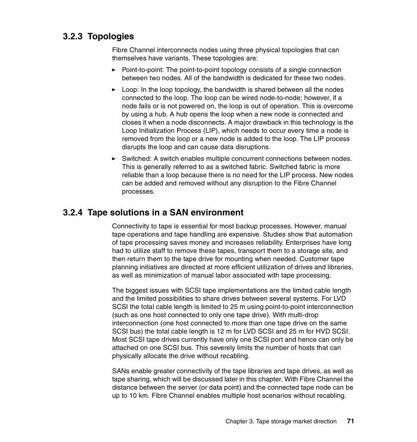
3.2.3 TopologiesFibre Channel interconnects nodes using three physical topologies that can themselves have variants. These topologies are:
� Point-to-point: The point-to-point topology consists of a single connection between two nodes. All of the bandwidth is dedicated for these two nodes.
� Loop: In the loop topology, the bandwidth is shared between all the nodes connected to the loop. The loop can be wired node-to-node; however, if a node fails or is not powered on, the loop is out of operation. This is overcome by using a hub. A hub opens the loop when a new node is connected and closes it when a node disconnects. A major drawback in this technology is the Loop Initialization Process (LIP), which needs to occur every time a node is removed from the loop or a new node is added to the loop. The LIP process disrupts the loop and can cause data disruptions.
� Switched: A switch enables multiple concurrent connections between nodes. This is generally referred to as a switched fabric. Switched fabric is more reliable than a loop because there is no need for the LIP process. New nodes can be added and removed without any disruption to the Fibre Channel processes.
3.2.4 Tape solutions in a SAN environmentConnectivity to tape is essential for most backup processes. However, manual tape operations and tape handling are expensive. Studies show that automation of tape processing saves money and increases reliability. Enterprises have long had to utilize staff to remove these tapes, transport them to a storage site, and then return them to the tape drive for mounting when needed. Customer tape planning initiatives are directed at more efficient utilization of drives and libraries, as well as minimization of manual labor associated with tape processing.
The biggest issues with SCSI tape implementations are the limited cable length and the limited possibilities to share drives between several systems. For LVD SCSI the total cable length is limited to 25 m using point-to-point interconnection (such as one host connected to only one tape drive). With multi-drop interconnection (one host connected to more than one tape drive on the same SCSI bus) the total cable length is 12 m for LVD SCSI and 25 m for HVD SCSI. Most SCSI tape drives currently have only one SCSI port and hence can only be attached on one SCSI bus. This severely limits the number of hosts that can physically allocate the drive without recabling.
SANs enable greater connectivity of the tape libraries and tape drives, as well as tape sharing, which will be discussed later in this chapter. With Fibre Channel the distance between the server (or data point) and the connected tape node can be up to 10 km. Fibre Channel enables multiple host scenarios without recabling.
Chapter 3. Tape storage market direction 71

If software to manage tape-drive sharing is not available, we would have to isolate (or zone) the drives to unique hosts using functions commonly available on SAN gateways or switches. With the proper management software, each drive can talk to each host, and connections can be dynamic without recabling.
Backup solutions can utilize SAN technology in a number of ways to reduce the costs of their implementation and at the same time increase their performance.
Sharing tape devices on a SAN environmentThe tape world has three distinct means of sharing:
� Library sharing� Drive sharing� Media sharing
Library sharingLibrary sharing occurs when multiple servers attached to a tape library share both the library and the robotics. The tape drives within the library may or may not be shared (pooled) among the attached servers. Tape library sharing is a prerequisite for tape-drive sharing.
Drive sharingThe sharing of one or more tape drives between multiple servers is called drive sharing. To share drives between heterogeneous applications within a tape library, the tape library must provide multiple paths to the robotics and also must have the capability to define the library’s drives and slots as multiple logical libraries. The server attached to each partition has no knowledge of any drives or slots outside the partition.
Media sharingMedia sharing today is only possible in a homogeneous environment between servers that use the same backup server and the same library to back up their data. For systems that are not backed up by the same backup server it is only possible to share a tape scratch pool.
Figure 3-16 on page 73 shows the multi-path architecture of the 3584 LTO tape library. Every drive can have a path defined to the SCSI Medium Changer (SMC).
The library on the left has been partitioned into three logical libraries. In the AIX and NT partitions, only the first drive has a library control path defined.
The iSeries is unique in that every IOP/IAP has to have a library control path defined. The iSeries attached to the left-hand library has two SCSI buses and therefore, two library control paths defined. These three servers are sharing the 3584 LTO tape library but not the drives.
72 The IBM LTO Ultrium Tape Libraries Guide

The library on the right has not been partitioned, and has only one logical library. Every iSeries SCSI bus has a library control path defined to allow control of the 3584 robotics. The iSeries supports the attachment of one Ultrium 1 LTO tape drive and of up to 15 Ultrium 2 LTO tape drives per SCSI bus.
The iSeries Servers attached to the right-hand library are also sharing the library even thoughit has not been partitioned. Through BRMS the iSeries Servers are sharing the library and media, but no tape-drive pooling is being done.
Figure 3-16 IBM 3584 multi-path architecture
IBM LTO in SAN environmentThe new IBM LTO Ultrium 2 Tape Drives are available with a Fibre Channel interface for either point-to-point or Fibre Channel-Arbitrated Loop attachment. These options remove the need to use a SAN data gateway. The device can be attached directly to SAN switches or FC-AL hubs.
For IBM LTO Ultrium 1 Tape Drives, SAN attachment must occur via a SAN data gateway. For drives with LVD interfaces, attachment must be through the SAN Data Gateway Router, 2108-R03. For drives with HVD interfaces, attachment must be through either the SAN Data Gateway Router, 2108-R03, or the SAN Data Gateway for Tape, 2108-G07.
In each case, the server will require a supported Fibre Channel HBA.
Max hosts in frame =
number of drives in the
Frame
DRIVE
1
DRIVE
2
Logical Library 1
Logical Library 2
Logical Library 3
FRAM E CONTR OLLER
(SCSI M e d iu m Ch a ng e r)
DRIVE
3
DRIVE
4
DRIVE
5
DRIVE
6
to Host 1
to Host 2
to Host 3
iSeries
Windows
pSeries
Multiple hosts 'owning' separate logical library inventories & drives
Max hosts in Library = number of
drives in the Library
DRIVE
1
DRIVE
2
Logical Library
1
FRAM E CONTROLLER
(SCSI M e dium Cha n ge r)
DRIVE
3
DRIVE
4
DRIVE
5
DRIVE
6
to Host 2
to Host 3
to Host 1
Multiple hosts sharing onelogical library inventory
iSeriesw BRMS
Chapter 3. Tape storage market direction 73

Backup software for SAN environmentsImplementing backup solutions in a SAN topology requires software developed to enable the sharing of tape drives at a logical level. The major benefits of this software are:
� Direct connection of the tape drive to the server for high speed� Sharing the drive with another server to save money
All you need is the proper traffic control feature at a software level.
The development of backup software solutions supporting tape-sharing on SAN is an ongoing process, and many of the back-up software vendors have already delivered products or plan to deliver such a product. IBM has made tape-sharing available for IBM Tivoli Storage Manager since Version 3.7 (October 1999).
Using electronic vaulting for disaster recoveryAnother important aspect of using tape in a SAN is the opportunity to exploit tape connectivity for disaster recovery enhancements. Today most enterprises take their tape backups offsite for disaster recovery. The tape is actually created in a locally attached tape library, then ejected from the library, and finally removed to an offsite location. All of this requires manual intervention and is error-prone. A major reason for failed recoveries is caused by a tape being mis-placed.
Fibre Channel SANs enable the backup server to create tapes easily and safely in a remotely attached tape library. This is called electronic vaulting. It removes all of the manual effort, as the tape is already offsite, and prevents a major cause of disaster-recovery failure. Currently, most enterprises staff tape operations to handle the tapes as they come and go from offsite storage. Fibre Channel allows for greater distances, so it becomes much easier to put a remote tape library at another location to create the backup tape copy. With this method, outlined in Figure 3-17 on page 75, no manual handling is necessary.
74 The IBM LTO Ultrium Tape Libraries Guide

Figure 3-17 Electronic vaulting
LAN-free backupSAN technology provides an alternative path for data movement between the backup client and the server. Shared storage resources (disk, tape) are accessible to both the client and the server through the SAN. Data movement is off-loaded from the LAN and from the server processor and allows for greater scalability. LAN-free backups decrease the load on the LAN.
Managed System for SAN is a feature of IBM Tivoli Storage Manager that enables LAN-free data movement. The Tivoli Storage Manager client data moves directly to and from a storage device attached to a SAN. A Tivoli Storage Manager storage agent is installed on the client machine and shares storage resources with the Tivoli Storage Manager server. The storage agent can write directly to storage media in a format that is consistent with that used by the server. The Tivoli Storage Manager server or servers controls the storage devices and keeps track of the data that the client has stored. Tivoli Storage Manager continues to use a LAN connection to exchange control information, such as policy information and data about the objects that are backed up. Using the SAN for client data movement decreases the load on the Tivoli Storage Manager server and allows the server to support a greater number of simultaneous client connections. See Figure 3-18 on page 76.
Backup Server
LAN SAN
Local Tape Library
Remote Tape Library
FC Extender
FC Extender
Chapter 3. Tape storage market direction 75

Figure 3-18 Tivoli Storage Manager LAN-free backup
The storage agent communicates with the server via the LAN to obtain and store database information and to coordinate device and volume access. The server determines if the client is requesting access to storage for which the client has a SAN path defined. If a SAN path is defined, the client (by means of the storage agent) transfers data on that path. If a failure occurs on the SAN path, failover occurs and the client uses its LAN connection to the Tivoli Storage Manager server and moves the client data over the LAN.
Server-free backupServer-free data movement provides a way to back up and restore large volumes of data between client-owned disks and storage devices in a method that reduces overhead on the backup server and the backup client, and that minimizes data transfer on the LAN. This is done by making use of the SCSI–3 extended copy command. The command is issued and initiated by the server and carried out by a data mover device (e.g. SAN Data Gateway) that exists on the SAN. The data mover device is responsible for moving the data either from a SAN-attached client-owned disk to a SAN-attached tape drive, or from a SAN-attached tape drive to a SAN-attached client-owned disk, which frees the server and the client from the operation. The process is shown in Figure 3-19 on page 77.
ITSM Library Manager Server
LAN SAN
Tape Library
TSM Clients- Storage Agent Disk
76 The IBM LTO Ultrium Tape Libraries Guide

Server-free backup/restore capability was introduced into IBM Tivoli Storage Manager in Version 5 for certain platforms. For more information on server-free capabilities of Tivoli Storage Manager, see the support page at http://www-3.ibm.com/software/tivoli/products/storage-mgr-san/platforms.html and the redbook IBM Tivoli Storage Manager Version 5.1 Technical Guide, SG24-6554.
Figure 3-19 Tivoli Storage Manager server-free backup
TSM Library Manager Server
LAN SAN
Tape Library
TSM Clients- Storage Agent Disk
Datamover
Chapter 3. Tape storage market direction 77

78 The IBM LTO Ultrium Tape Libraries Guide

Chapter 4. IBM TotalStorage Ultrium Tape Drive 3580
The IBM TotalStorage Ultrium Tape Drive 3580 is the smallest in the family of IBM Ultrium tape solutions. It is an external, stand-alone, SCSI-attached tape drive that attaches to iSeries, pSeries, xSeries, RS/6000® SP, and other UNIX and PC servers supporting OS/400®, IBM AIX, Sun Solaris™, HP-UX, Microsoft Windows NT, Microsoft Windows 2000, Microsoft Windows 2003, and Red Hat and SuSE Linux using a suitable SCSI adapter.
The IBM 3580 Ultrium tape drive is a very cost-effective solution for save-and-restore and archiving functions, and it provides an excellent migration path from SDLT, 1/4-inch, 4 mm, or 8 mm tape drives.
4
© Copyright IBM Corp. 2000, 2003. All rights reserved. 79

4.1 Model descriptionThe IBM 3580 is a large-capacity, high-performance Ultrium tape drive available as six separate model types, depending on the capacity and SCSI1 interface required.
Figure 4-1 IBM 3580 model L11/L13/L23 or H11/H13/H23 Ultrium tape drive
There are six model types:
� IBM 3580-L11 and IBM 3580-L13 have 100GB native capacity with a Low-Voltage Differential (LVD) Ultra2 SCSI attachment that connects to LVD fast/wide adapters.
� IBM 3580-H11 and IBM 3580-H13 have 100GB native capacity with a High-Voltage Differential (HVD) Ultra SCSI attachment that connects to HVD fast/wide adapters.
� IBM 3580-L23 has 200GB native capacity with a Low-Voltage Differential (LVD) Ultra2 SCSI attachment that connects to LVD fast/wide adapters.
� IBM 3580-H23 has 200GB native capacity with a High-Voltage Differential (HVD) Ultra SCSI attachment that connects to HVD fast/wide adapters.
The IBM 3580 models L11, L13, H11, and H13 all use the Ultrium 1 LTO cartridge, which has a capacity of 100GB (200GB with 2:1 compression), and are capable of sustaining a data rate of up to 15 MB/s (uncompressed).
1 Refer to 2.4.3, “Interfaces” on page 31 for an explanation of HVD and LVD.
80 The IBM LTO Ultrium Tape Libraries Guide

The IBM 3580-L11 and IBM 3580-L13 are functionally identical. The only difference is that the IBM 3580-L13 has a three-year Customer Element Exchange warranty. The IBM 3580-H11 and IBM 3580-H13 are functionally identical; the only difference is that the IBM 3580-H13 has a three-year Customer Element Exchange warranty.
The IBM 3580-L23 and H23 use the Ultrium 2 LTO cartridge, which has a capacity of 200GB (400GB with 2:1 compression), and are capable of sustaining a data rate of up to 35 MB/s (uncompressed).
4.2 Feature codesThe IBM 3580 Ultrium tape drive can be ordered with the following feature codes (Table 4-1). We have not included the various cabling options; refer to the product publications for detailed information about configuring and ordering it.
Table 4-1 IBM 3580 feature codes
Note: Although the IBM 3580 Ultrium tape drive provides the capability for high tape performance, other components of the system may limit the actual performance achieved. Also, the actual degree of compression achieved is highly sensitive to the characteristics of the data being compressed.
Feature code Description Comments
1748 Custom QuickShip
8001 One 100GB data cartridge Plant only; see Media section for details.
8101 One 200GB data cartridge Plant only; see Media section for details.
8002 One cleaning cartridge Plant only; see Media section for details.
8723 Rack mount kit
9210 Attached to HP-UX
9211 Attached to Sun
9212 Attached to Windows
9213 Attached to other non-IBM
9215 Attached to Linux
Chapter 4. IBM TotalStorage Ultrium Tape Drive 3580 81

4.3 SCSI attachment
The SCSI interface (HVD or LVD) on each IBM 3580 Ultrium tape drive is chosen by selecting the appropriate model number (model H11/13/23 or L11/L13/23).
The IBM 3580 Ultrium tape drive can be attached to IBM pSeries, IBM xSeries, IBM RS/6000 SP systems, IBM iSeries, AS/400, and non-IBM servers, workstations, and personal computers that support Ultra/Wide SCSI HVD and Ultra2/Wide SCSI LVD interface specifications. The interface you choose will depend on the available adapter in the host, which must be of the same type as the drive interface.
The IBM 3580 Ultrium tape drive also may be compatible with other servers, operating systems, and SCSI adapters. Contact your local IBM representative for a current list of supported open system configuration and software vendors or visit http://www.ibm.com/storage/lto.
4.4 SCSI cablingA SCSI cable is required for each IBM 3580 connection to a SCSI bus. A single 2.5 m SCSI cable is available as a no-charge feature; if an alternate length is required it should be included in the initial order. A SCSI terminator is included with each drive.
An interposer (a connector that matches the pin pattern of the host adapter to the pin pattern of the cable) also may be required for attachment to particular server adapters.
4.4.1 CablesA single SCSI cable is available as a no-charge feature (either #9702 or #9703) specified only with the initial IBM 3580 order. It is not orderable as a miscellaneous equipment specification (MES) for installation later. Feature #9702 supplies a 2.5 m universal SCSI cable with HD68 connectors at each end; feature #9703 supplies a VHDCI connector at one end and HD68 at the other.
9400 Attached to AS/400®
9600 Attached to AIX
Feature code Description Comments
82 The IBM LTO Ultrium Tape Libraries Guide

Additional SCSI cables are available as optional features on the IBM 3580 for LVD and HVD attachment to host adapters.
The following cables have an HD68 connector at each end:
� Feature #5301, 0.4 m (1.4 feet) SCSI cable � Feature #5302, 2.5 m (6.6 feet) SCSI cable� Feature #5305, 5 m (16.5 feet) SCSI cable� Feature #5310, 10 m (33 feet) SCSI cable� Feature #5318, 18 m (60 feet) SCSI cable� Feature #5325, 25 m (82 feet) SCSI cable
The following cables have a VHDCI connector at one end and an HD68 connector at the other end:
� Feature #5602, 2.5 m (6.6 feet) SCSI cable� Feature #5604, 4.5 m (14.5 feet) SCSI cable� Feature #5610, 10 m (33 feet) SCSI cable� Feature #5620, 20 m (66 feet) SCSI cable� Feature #5625, 25 m (82 feet) SCSI cable
4.4.2 InterposersAn interposer may be required to connect host adapters that do not have HD68 connectors to the SCSI cables. The following chargeable interposers are available:
� Feature #2895 interposer to connect iSeries adapter #6501.
� Feature #5099 interposer to connect a mini-68-pin VHDCI connector to the 68-pin HD68 connector on the SCSI cable. The interposer (a 0.3 m cable) has a male mini-68-pin VHDCI connector on one end and a female 68-pin HD68 connector on the other.
4.4.3 SCSI length limitationsThe overall LVD SCSI cable length is limited to 25 m (81 feet) using point-to-point interconnection. If using multi-drop interconnection, then the overall LVD SCSI cable length is limited to 12 m (39 feet). The stub length at each device must not exceed 0.1 m (0.33 feet).
The overall HVD SCSI cable lengths are limited to 25 m (81 feet) using point-to-point or multi-drop interconnection. The stub length at each device must not exceed 0.2 m (0.66 feet).
Chapter 4. IBM TotalStorage Ultrium Tape Drive 3580 83
4.5 UpgradesThe IBM 3580-L11/L13 and IBM 3580-H11/H13 cannot be upgraded to IBM 3580-L23 and IBM 3580-H23, respectively.
IBM 3580 drives cannot be installed into IBM 3581, 3582, 3583, or 3584 units.
4.6 Environmental specificationsThe IBM 3580 is designed to be placed on or beside the attached host server or installed in a standard 19-inch rack.
4.6.1 Physical dimensionsThe IBM 3580 is a relatively small single tape drive enclosure:
� Width: 17.1 cm (6.75 in)� Depth: 33.3 cm (13.1 in)� Height: 14.6 cm (5.75 in)� Maximum weight: 6.6 kg (14.3 lbs)
4.6.2 Operating environmentThe IBM 3580 can be installed in a normal office environment and does not need to be in a specialized machine room. Refer to the product publications for specific information.
4.7 Host platforms and device driversThe following no-charge specify codes indicate the server platform to which the IBM 3580 Ultrium tape drive is attached:
� #9210, attached to HP-UX� #9211, attached to Sun System� #9212, attached to Windows NT or Windows 2000 System� #9213, attached to other non-IBM system � #9215, attached to Linux system� #9400, attached to AS/400 System� #9600, attached to RS/6000
A device driver is additional code on the host server platform that enables it to recognize and talk to a peripheral device (in this case, the IBM 3580). Sometimes the driver code is supplied as part of the operating system code (for example, in
84 The IBM LTO Ultrium Tape Libraries Guide
OS/400), sometimes a software patch is required, and sometimes the driver is installed separately from a CD or diskette (either an OS CD or provided with a vendor application).
Ultrium 1The IBM 3580 is shipped with device drivers to support Ultrium 1 drives in the following operating environments at the minimal levels shown:
� AIX Versions 4.3.2 or later� Sun Solaris 2.6, 7, and 8� Windows NT 4.0 with Service Pack 6� Windows 2000 build 2195 or greater� HP-UX 11.0� OS/400 V4R4
Ultrium 2The IBM 3580 is shipped with device drivers to support Ultrium 2 drives in the following operating environments at the minimal levels shown:
� AIX Versions 4.3.3, 5.1� Sun Solaris 7, 8, and 9� Windows NT 4.0 with Service Pack 6� Windows 2000 (build 2195)� Windows 2003� HP-UX 11.0, 11i� OS/400 V5R1, V5R2� Linux Red Hat 7.2 (32 and 64 bit kernels), Red Hat 7.3, Red Hat Advanced
Server 2.1, SuSE Linux Enterprise Server Update
4.7.1 Device driver installationInstall the IBM device drivers for the IBM 3580 as follows:
� If you intend to use the IBM 3580 with a commercial software application (such as IBM Tivoli Storage Manager, VERITAS Backup Exec, or Legato NetWorker), refer to that application’s installation instructions to install the device driver and configure the IBM 3580.
Tip: The device driver CD or diskette that is shipped with the IBM 3580 may not contain the device drivers with the most recent level or the device drivers for all supported systems. Always check the following FTP site for the latest device drivers:
ftp://ftp.software.ibm.com/storage/devdrvr/
Chapter 4. IBM TotalStorage Ultrium Tape Drive 3580 85

� If you do not intend to use the IBM 3580 with a commercial software application, install the tape and medium device driver from the CD that is shipped with the drive. Refer to the installation instructions in the IBM SCSI Tape Drive, Medium Changer, and Library Device Drivers Installation and User’s Guide GC35-0154, which is supplied on the CD with the driver code.
4.8 Storage applicationsThe software to manage the IBM 3580 Ultrium tape drive is not provided with the libraries. Additional software support is available through library management software products that must be obtained separately from IBM, IBM Business Partners, or independent software providers. A list of compatible software is available at the Web site:
http://www.storage.ibm.com/hardsoft/tape/conntrix/pdf/lto_isv_matrix.pdf
You will find details for each application including Ultrium support and specific Ultrium models and attachment methods. You should also contact your storage application vendor for more detailed information of specific versions and platforms supported.
4.9 Performance considerationsFor best performance, it is recommended to attach only one tape drive per SCSI bus. This may not be a realistic objective, but minimizing the number of devices per bus will improve performance. Attaching other SCSI devices on the same SCSI bus as the IBM 3580 Ultrium tape drive may affect performance of those devices.
iSeries configurators allow only one drive per input/output port for maximum performance. Installing more than one Ultrium tape drive on an input/output port may affect system performance.
Note: If you use the IBM 3580 with a commercial software application, IBM recommends that you install any IBM supplied device driver only if instructed to do so in the installation instructions supplied by the vendor of the application. Otherwise, if the application supplies its own driver code, then conflicts could occur over which driver controls the drive. Many examples of using the Ultrium drives are given in the Redbooks Implementing IBM LTO in Linux and Windows, SG24-6268, and Using IBM LTO Ultrium with Open Systems, SG24-6502.
86 The IBM LTO Ultrium Tape Libraries Guide

Although the compression technology can increase the amount of data stored on the media, the actual degree of compression achieved is highly sensitive to the characteristics of the data being compressed.
4.10 MediaOne Ultrium cleaning cartridge and one Ultrium data cartridge are included with each IBM 3580 drive order2. With the initial order, additional data and cleaning cartridges may be ordered as chargeable features for the IBM 3580:
� Feature #8001 provides a single 100 MB Ultrium 1 Data Cartridge.It is a chargeable feature, and a maximum of five can be ordered.
� Feature #8101 provides a single 200 MB Ultrium 2 Data Cartridge.Additional cartridges can be ordered using part number #08L9870.
� Feature #8002 provides a single Ultrium Cleaning Cartridge.It is a chargeable feature, and a maximum of three can be ordered.
Subsequent to the initial order, additional supplies can be ordered from the IBM media business or a third-party media vendor. Refer to Appendix A, “LTO Ultrium tape media” on page 223 for details about how to order supplies and cartridges, with or without labels.
4.11 IBM 3580 Ultrium tape drive initial set-upThis section covers some of the major items required to implement, manage, and operate the IBM 3580 tape drives. It does not cover all of the tasks, nor do we intend to cover all the specific commands. For more details, refer to IBM 3580 Ultrium Tape Drive Setup, Operator and Service Guide, GA32-0415, IBM TotalStorage LTO Ultrium 2 Tape Drive 3580 Setup and Operator Guide, GA32-0460, and the Redbooks Implementing IBM LTO in Linux and Windows, SG24-6268 and Using IBM LTO Ultrium with Open Systems, SG24-6502.
4.11.1 SCSI IDIf you attach multiple IBM 3580 SCSI devices in the same chain, they should each use different SCSI IDs starting with the lowest number on the first device as depicted in Figure 4-2 on page 88. The last device of that SCSI chain must have a valid terminator. The SCSI ID set-up button is located at the rear of the IBM 3580.
2 All media and cleaning cartridges are warranted separately from the IBM 3580 Ultrium tape drive.
Chapter 4. IBM TotalStorage Ultrium Tape Drive 3580 87

Figure 4-2 SCSI ID set-up example
4.12 Operator displays and buttonsThe IBM 3580 Ultrium tape drive has a simple operating interface consisting of:
� A status light� A message display� A single character display� A push button
4.12.1 Status lightThe status light (labeled 2 in Figure 4-3 on page 90) provides information about the state of the IBM 3580 tape drive. The light can be green or amber, and, when lit, solid or flashing. These are the possible conditions of the status light and an explanation of what each condition means:
� Off: The IBM 3580 tape drive has no power, or is powered off, or if C displays simultaneously in the single-character display (see label 3 in Figure 4-3 on page 90), it needs cleaning.
� Green/solid: The IBM 3580 tape drive is idle.
� Green/flashing: The IBM 3580 tape drive is reading or writing data, rewinding the tape, locating data on the tape, or unloading the tape.
� Yellow/solid: The IBM 3580 tape drive is in maintenance mode, or is running power-on self-test diagnostic routines.
SCSI ID #7SCSI ID #1
SCSI ID #2
SCSI ID #3
88 The IBM LTO Ultrium Tape Libraries Guide

� Yellow/flashing: One of the following applies:
– If the light flashes once per second, an error occurred and the tape drive or media may require service. Note the code on the single-character display. Refer to the Setup and Operator Guides (GA32-0415 for Ultrium1 or GA32-0460 for Ultrium 2).
– If the light flashes twice per second, the tape drive is updating firmware.
– If the light flashes four times per second, the tape drive detected an error and is performing a firmware recovery. It resets automatically.
4.12.2 Message displayThe message display (labeled 4 in Figure 4-3 on page 90) is a liquid crystal display (LCD) that provides information about the status of the tape drive and error conditions.
The message display consists of two rows, with 20 characters available in each row. During operation, the IBM 3580 tape drive continuously queries the drive and updates the display with status messages. When in an idle (non-operating) state, the tape drive displays the following messages:
Ultrium Tape DriveDrive Empty
4.12.3 The single-character displayThe IBM 3580 tape drive features a light-emitting diode (LED) display (labeled 3 in Figure 4-3 on page 90 below). The LED presents a single-character code for:
� Error conditions and informational messages� Diagnostic or maintenance functions (while in maintenance mode only)
For the list of messages, refer to the Setup and Operator Guides (GA32-0415 for Ultrium1 or GA32-0460 for Ultrium 2).
If multiple errors occur, the code with the highest priority (represented by the lowest number) displays first. When the error is corrected, the code with the next highest priority displays, and so on, until no errors remain.
The single-character display is blank during normal operation of the IBM 3580 tape drive.
Chapter 4. IBM TotalStorage Ultrium Tape Drive 3580 89

Figure 4-3 Front view of the IBM 3580 tape drive
4.12.4 Unload push buttonThe unload push button (labeled 1 in Figure 4-3) enables you to perform several functions. You can:
� Rewind the tape from the cartridge and eject the cartridge from the tape drive.� Place the tape drive in maintenance mode� Scroll through the maintenance menus� Exit from the maintenance mode.
4.13 Drive cleaning All IBM Ultrium tape drives have an integrated cleaning mechanism that brushes the head at cartridge load time and again when unloading a cartridge. Along with this, the drives have a cleaning procedure that uses a special cleaning cartridge.
To clean the head, insert the cleaning cartridge into the tape load compartment. The tape drive performs the cleaning operation automatically. When the cleaning operation is finished, the drive ejects the cartridge.
1234
Attention: If you press the Unload button during operation, the IBM 3580 tape drive ends the current job, and unloads and ejects the tape cartridge.
90 The IBM LTO Ultrium Tape Libraries Guide
The IBM 3580 needs cleaning when the IBM 3580 tape drive status light (label 2 in Figure 4-3 on page 90) is OFF and C displays simultaneously in the single-character display (label 3 in Figure 4-3 on page 90). This is the only occasion when a cleaning cartridge should be used. For normal operation, the integrated cleaning mechanism ensures that the head remains clean.
4.14 Firmware upgradeEach IBM Ultrium Tape drive contains IBM Licensed Internal Code, often referred to as firmware. At installation time, you should make sure the latest firmware level is installed on your IBM LTO tape drive. As the IBM 3580 is designated as a Customer Setup Machine, it is the customer’s responsibility to have current firmware installed.
Determine the latest level of firmware available from the Web site:
http://www-1.ibm.com/support/docview.wss?rs=543&org=ssg&doc=S4000055&loc=en-us
Follow the instructions for updating your firmware in the Setup and Operator Guides (GA32-0415 for Ultrium1 or GA32-0460 for Ultrium 2) or from:
http://ssddom02.storage.ibm.com/techsup/webnav.nsf/support/ltofaqs_updatefw_drivefw
Attention: When cleaning the drive head, use only the IBM LTO Ultrium Cleaning Cartridge or an IBM-approved cleaning cartridge.
Chapter 4. IBM TotalStorage Ultrium Tape Drive 3580 91

92 The IBM LTO Ultrium Tape Libraries Guide
Chapter 5. IBM TotalStorage Ultrium Tape Autoloader 3581
The IBM TotalStorage Ultrium Tape Autoloader 3581 (see Figure 5-1 on page 95) is the second product in the IBM LTO Ultrium family. It is an external, single-drive, SCSI-attached, stand-alone or rack-mounted autoloader that attaches to iSeries, AS/400, pSeries, RS/6000, RS/6000 SP, xSeries, Netfinity®,Microsoft Windows NT, Microsoft Windows 2000, Windows 2003, Sun Solaris, HP-UX, and Linux systems using a SCSI adapter.
The IBM TotalStorage Ultrium Tape Autoloader 3581 uses a single IBM LTO Ultrium tape drive. The autoloader contains seven tape slots1 providing a media capacity of up to 700 GB (1.4 TB with 2:1 compression) per autoloader, and is capable of sustaining a data rate of up to 15 MBps (uncompressed).
The IBM TotalStorage Ultrium Tape Autoloader 3581 is an excellent solution for customers who use tape and require a larger capacity or higher performance tape backup, with or without random access, than is provided by their current tape system. With its higher capacity and performance, the 3581 is an excellent replacement for other externally attached DLT, SDLT, 1/4-inch, 4 mm, or 8 mm tape devices for the iSeries, AS/400, pSeries, RS/6000, RS/6000 SP, xSeries, and Netfinity families of workstations and servers.
5
1 When the optional barcode reader is installed the cartridge capacity is reduced to six.
© Copyright IBM Corp. 2000, 2003. All rights reserved. 93
For capacity and performance requirements beyond a single IBM Ultrium drive and seven IBM Ultrium tape cartridges, consider other solutions in the IBM Ultrium familysuch as the IBM TotalStorage Tape Library 3582, IBM TotalStorage Ultrium Scalable Tape Library 3583, or IBM TotalStorage UltraScalable Tape Library 3584.
94 The IBM LTO Ultrium Tape Libraries Guide

5.1 Model descriptionThe IBM TotalStorage Ultrium Tape Autoloader 3581 is a high-performance Ultrium tape autoloader. It is available as four separate model types, depending on the capacity and required SCSI2 interface.
Figure 5-1 IBM TotalStorage Ultrium Tape Autoloader 3581
The four models are:
� IBM 3581-L17 and IBM 3581-L13 have seven cartridge slots, a .7 TB native data capacity with a Low-Voltage Differential (LVD) Ultra2 SCSI attachment that connects to LVD fast/wide adapters.
� IBM 3581-H17 and IBM 3581-L13 have seven cartridge slots, a .7 TB native data capacity with a High-Voltage Differential (HVD) Ultra SCSI attachment that connects to HVD fast/wide adapters.
The IBM 3581-L17, -L13, -H17, and -H13 all use the same Ultrium 1 LTO cartridge, which has a capacity of 100GB (200GB with 2:1 compression), and are capable of sustaining a data rate of up to 15 MB/s (uncompressed).
2 Refer to2.4.3, “Interfaces” on page 31 for an explanation of HVD and LVD.
Chapter 5. IBM TotalStorage Ultrium Tape Autoloader 3581 95
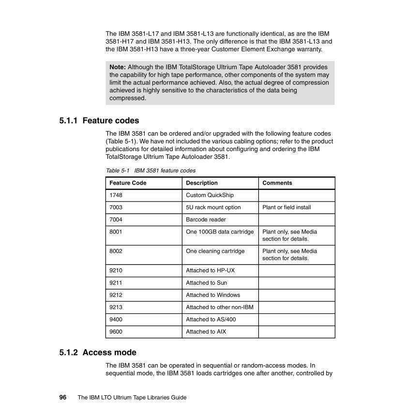
The IBM 3581-L17 and IBM 3581-L13 are functionally identical, as are the IBM 3581-H17 and IBM 3581-H13. The only difference is that the IBM 3581-L13 and the IBM 3581-H13 have a three-year Customer Element Exchange warranty.
5.1.1 Feature codesThe IBM 3581 can be ordered and/or upgraded with the following feature codes (Table 5-1). We have not included the various cabling options; refer to the product publications for detailed information about configuring and ordering the IBM TotalStorage Ultrium Tape Autoloader 3581.
Table 5-1 IBM 3581 feature codes
5.1.2 Access modeThe IBM 3581 can be operated in sequential or random-access modes. In sequential mode, the IBM 3581 loads cartridges one after another, controlled by
Note: Although the IBM TotalStorage Ultrium Tape Autoloader 3581 provides the capability for high tape performance, other components of the system may limit the actual performance achieved. Also, the actual degree of compression achieved is highly sensitive to the characteristics of the data being compressed.
Feature Code Description Comments
1748 Custom QuickShip
7003 5U rack mount option Plant or field install
7004 Barcode reader
8001 One 100GB data cartridge Plant only, see Media section for details.
8002 One cleaning cartridge Plant only, see Media section for details.
9210 Attached to HP-UX
9211 Attached to Sun
9212 Attached to Windows
9213 Attached to other non-IBM
9400 Attached to AS/400
9600 Attached to AIX
96 The IBM LTO Ultrium Tape Libraries Guide

the hardware when it receives the unload command from the host server. In random-access mode, the IBM 3581 relies on application software for cartridge management.
5.1.3 SCSI devicesAlthough it has only a single tape drive, the 3581 appears as two SCSI devices on the SCSI bus. In other words, the autoloader and the drive have separate SCSI addresses.
The IBM 3581 only operates on a single path, and control of the autoloader is handled by a single server. Connection to multiple servers can be achieved when using SAN technology and appropriate application software for cartridge management, such as IBM Tivoli Storage Manager V3.7 or higher.
5.1.4 Adding and removing cartridges The IBM 3581 does not have a cartridge I/O station. In order to insert and remove cartridges from the slots you have to open the autoloader door. The IBM TotalStorage Ultrium Tape Autoloader 3581 can contain up to seven tape cartridges:
� Five cartridges in the front, slots 1 through 5 (referred to as front slots; see label 1 in Figure 5-2)
� Two cartridges in the rear, slots 6 and 7 (referred to as rear slots; see label 2 in Figure 5-2)
Figure 5-2 IBM 3581 cartridge slots
1
2
Chapter 5. IBM TotalStorage Ultrium Tape Autoloader 3581 97
5.1.5 OperationThe IBM 3581 autoloader is designed for easy, unattended operation. An optional barcode reader makes tape inventory tasks more efficient. Indicators on the operator’s panel provide information about:
� Power� Autoloader and drive activity� Error status� Message information
Push buttons provide display, mode, and power controls.
5.2 SCSI attachmentsThe SCSI interface (HVD or LVD) on each IBM TotalStorage Ultrium Tape Autoloader 3581 is chosen by selecting the appropriate model number (H17/13 or L17/13).
The IBM TotalStorage Ultrium Tape Autoloader 3581 can be attached to iSeries, AS/400, pSeries, RS/6000, xSeries, Netfinity, HP, Sun, UNIX, and PC servers that support Ultra/Wide SCSI HVD and Ultra2/Wide SCSI LVD interface specifications. The interface you choose will depend on the available adapter in the host, which must be of the same type as the drive interface.
SCSI cables and appropriate interposers, as required, should be ordered for attachment to a server. A power cord feature code should also be specified.
The IBM TotalStorage Ultrium Tape Autoloader 3581 also may be compatible with other servers, operating systems, and SCSI adapters. Contact your local IBM representative for a current list of supported open system configuration and software vendors. You also may refer to the Interoperability Matrix (List of Supported Servers) on this Web site:
http://www.storage.ibm.com/tape/lto/3581/3581opn.pdf
5.3 SCSI cablingA SCSI cable is required for each 3581 connection to a SCSI bus. A single 2.5 m SCSI cable is available as a no-charge feature; if an alternate length is required it should be included in the initial order. A SCSI terminator is included with each autoloader. An interposer (a connector that matches the pin pattern of the host adapter to the pin pattern of the cable) also may be required for attachment to particular server adapters.
98 The IBM LTO Ultrium Tape Libraries Guide

5.3.1 CablesA single SCSI cable is available as no-charge feature #9702 or #9703 only with the initial IBM 3581 order. These no-charge features cannot be ordered later as a miscellaneous equipment specification (MES); however, the same cables can be ordered later as chargeable MES upgrades using feature codes #5302 and #5602. Feature #9702 supplies a 2.5 m SCSI cable with HD68 connectors at each end; feature #9703 differs in that one end has a VHDCI connector.
Additional SCSI cables are available as optional features on the IBM 3581 for LVD and HVD attachment to host adapters:
� Feature #5301, 0.4 m (1.4 feet) SCSI cable � Feature #5302, 2.5 m (8.2 feet) SCSI cable� Feature #5305, 5 m (16.5 feet) SCSI cable� Feature #5310, 10 m (33 feet) SCSI cable� Feature #5318, 18 m (60 feet) SCSI cable� Feature #5325, 25 m (82 feet) SCSI cable
The cables can be used with an HVD Ultra SCSI bus or LVD Ultra2 SCSI bus and have an HD68 connector on each end. A SCSI terminator is included with each Ultrium autoloader.
The following cables differ in that they have a VHDCI connector at one end:
� Feature #5602, 2.5 m (8.2 feet) SCSI cable� Feature #5604, 4.5 m (14.5 feet) SCSI cable� Feature #5610, 10 m (33 feet) SCSI cable� Feature #5620, 20 m (66 feet) SCSI cable� Feature #5625, 2 5m (82 feet) SCSI cable
5.3.2 InterposersAn interposer is required to connect host adapters that do not have HD68 connectors to the SCSI cables. The following chargeable interposers are available:
� Feature #2895 interposer to connect iSeries adapter #6501.
� Feature #5099 interposer to connect a mini-68-pin VHDCI connector to the 68-pin HD68 connector on the SCSI cable.
This interposer (a 0.3 m cable) has a male mini-68-pin VHDCI connector on one end and a female 68-pin HD68 connector on the other.
Chapter 5. IBM TotalStorage Ultrium Tape Autoloader 3581 99

5.3.3 SCSI length limitationsThe IBM 3581 has one SCSI ID for the drive and one for the loader, so the SCSI interconnection is multi-drop. This means that the overall LVD SCSI cable length is limited to 12 m (39 feet). The stub length at each device must not exceed 0.1 m (0.33 feet).
The overall HVD SCSI cable lengths are limited to 25 m (81 feet) using multi-drop interconnection. The stub length at each device must not exceed 0.2 m (0.66 feet).
5.4 Upgrades and optional featuresThe IBM 3581 H17/13 and L17/13 are single tape drive autoloaders and cannot be upgraded to any other models.
Two additional optional features are available:
� Feature #7003, 5U Rack Mount OptionThe IBM 3581 can be installed as a stand-alone single unit, or two units can be mounted side-by-side in a standard 19-inch rack, requiring 5 EIA units of rack space. This chargeable feature provides the necessary hardware to mount the autoloader in the rack.
� Feature #7004, Barcode ReaderThis optional chargeable feature enables the IBM 3581 autoloader to read cartridge information contained in a barcode label on the IBM Ultrium cartridges. User-installed application software provides the inventory management functions enabled by the barcode reader feature.
Note: Installing feature #7004 reduces the autoloader capacity to six data cartridges. The barcode reader connects to the interface connector on the inside top panel of the IBM 3581. This location prevents you from using cartridge storage slot 1 (see Figure 5-2 on page 97). When you install the barcode reader, you reduce the capacity of the autoloader to six cartridge storage slots. The front storage slots are still numbered 1 through 5, but the autoloader’s menu functions and the server’s application software cannot select or use slot 1.
This is illustrated by observing that, with the barcode reader installed, the operator LOAD SLOT function uses storage slots 2 and 3 as the cartridge source locations to load slots 6 and 7; without the barcode reader installed, the LOAD SLOT function uses storage slots 1 and 2 as the source locations. See Figure 5-2 on page 97 for slot locations.
100 The IBM LTO Ultrium Tape Libraries Guide
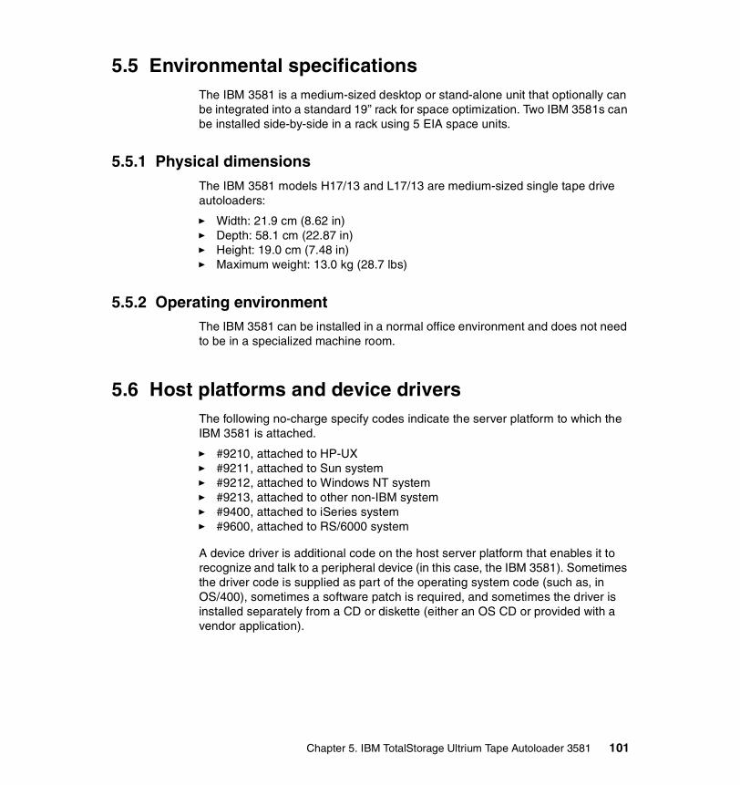
5.5 Environmental specificationsThe IBM 3581 is a medium-sized desktop or stand-alone unit that optionally can be integrated into a standard 19” rack for space optimization. Two IBM 3581s can be installed side-by-side in a rack using 5 EIA space units.
5.5.1 Physical dimensionsThe IBM 3581 models H17/13 and L17/13 are medium-sized single tape drive autoloaders:
� Width: 21.9 cm (8.62 in)� Depth: 58.1 cm (22.87 in)� Height: 19.0 cm (7.48 in)� Maximum weight: 13.0 kg (28.7 lbs)
5.5.2 Operating environmentThe IBM 3581 can be installed in a normal office environment and does not need to be in a specialized machine room.
5.6 Host platforms and device driversThe following no-charge specify codes indicate the server platform to which the IBM 3581 is attached.
� #9210, attached to HP-UX� #9211, attached to Sun system� #9212, attached to Windows NT system� #9213, attached to other non-IBM system� #9400, attached to iSeries system� #9600, attached to RS/6000 system
A device driver is additional code on the host server platform that enables it to recognize and talk to a peripheral device (in this case, the IBM 3581). Sometimes the driver code is supplied as part of the operating system code (such as, in OS/400), sometimes a software patch is required, and sometimes the driver is installed separately from a CD or diskette (either an OS CD or provided with a vendor application).
Chapter 5. IBM TotalStorage Ultrium Tape Autoloader 3581 101

Ultrium 1The IBM TotalStorage Ultrium Tape Autoloader is shipped with device drivers to support Ultrium 1 drives in the following operating environments at the minimal levels shown:
� AIX Versions 4.3.2 or later� Sun Solaris 2.6, 7, and 8� Windows NT 4.0 with Service Pack 6� Windows 2000 build 2195 or greater� Windows 2003� HP-UX 11.0� OS/400 V4R4
5.6.1 Device driver installationInstall the IBM device drivers for the IBM 3581 as follows:
� If you intend to use the IBM 3581 with a storage management application (such as Tivoli Storage Manager, VERITAS Backup Exec, or Legato NetWorker), refer to that application’s installation instructions to install the device driver and configure the IBM 3581.
� If you do not intend to use the IBM 3581 with a commercial software application, install the tape and medium device driver from the CD that is shipped with the autoloader. Refer to the installation instructions in the IBM SCSI Tape Drive, Medium Changer, and Library Device Drivers Installation and User’s Guide, GC35-0154, which is supplied on the CD with the driver code.
Tip: The device driver CD or diskette that is shipped with the IBM 3581 may not contain the device drivers with the most recent level or the device drivers for all supported systems. Therefore you should always check the following FTP site for the latest device drivers:
ftp://ftp.software.ibm.com/storage/devdrvr/
Note: If you use the IBM 3581 with a commercial software application, IBM recommends that you install an IBM-supplied device driver only if instructed to do so in the installation instructions supplied by the vendor of the application. Otherwise, if the application supplies its own driver code, conflicts could occur over which driver controls the tape subsystem. Many examples of using the Ultrium drives are given in the Redbooks Implementing IBM LTO in Linux and Windows, SG24-6268, and Using IBM LTO Ultrium with Open Systems, SG24-6502.
102 The IBM LTO Ultrium Tape Libraries Guide

5.7 Storage applicationsThe software to manage the IBM 3581 is not provided with the libraries. Additional software support is available through library management software products that must be obtained separately from IBM, IBM Business Partners, or independent software vendors. A list of compatible software is available at:
http://www.storage.ibm.com/hardsoft/tape/conntrix/pdf/lto_isv_matrix.pdf
You will find details for each application including Ultrium 1 and Ultrium 2 support and specific Ultrium models and attachment methods. You should also contact your storage application vendor for more-detailed information of specific versions and platforms supported.
5.8 Performance considerationsFor best performance, it is recommended to attach only one tape drive per SCSI bus. This may not be a realistic objective, but minimizing the number of devices per bus will improve performance. Attaching other SCSI devices on the same SCSI bus as the IBM 3581 drive may affect performance of those devices.
iSeries configurators allow only one drive per input/output port for maximum performance. Installing more than one Ultrium tape drive on an input/output port may affect system performance.
Although the compression technology can increase the amount of data stored on the media, the actual degree of compression achieved is highly sensitive to the characteristics of the data being compressed.
5.9 MediaOne Ultrium cleaning cartridge and one Ultrium data cartridge are included with each autoloader order3. With the initial order, additional data and cleaning cartridges may be ordered as chargeable features for the IBM 3581:
� Feature #8001 provides a single 100 MB Ultrium Data Cartridge.It is a chargeable feature, and a maximum of seven can be ordered.
� Feature #8002, provides a single Ultrium Cleaning Cartridge.It is a chargeable feature, and a maximum of three can be ordered.
3 All media and cleaning cartridges are warranted separately from the IBM TotalStorage Ultrium Tape Autoloader 3581.
Chapter 5. IBM TotalStorage Ultrium Tape Autoloader 3581 103

Subsequent to the initial order, additional supplies can be ordered from the IBM media business or a third-party media vendor. Refer to Appendix A, “LTO Ultrium tape media” on page 223 for details about ordering supplies and cartridges, with or without labels.
5.10 IBM 3581 initial setupThe following section covers some of the major items required to implement, manage, and operate the IBM 3581 tape library. It does not cover all tasks and we do not intend to cover all of the specific commands. For more details, refer to the Setup and Operator Guide and to the Redbooks Implementing IBM LTO in Linux and Windows, SG24-6268, and Using IBM LTO Ultrium with Open Systems, SG24-6502.
5.10.1 SCSI IDThe IBM 3581 consists of two SCSI devices: the autoloader and the drive. The default settings for the SCSI IDs as displayed on the message display panel are LdR Id 14 (for the autoloader) and dRV Id 3 (for the drive). Depending on your requirements, you may need to change the SCSI ID default settings for your installation. When setting a SCSI ID:
� Do not select an ID that is already in use.
� Do not select the SCSI ID of the server SCSI adapter card. The SCSI ID of the server SCSI adapter card is usually higher than any device on the SCSI bus. Generally, the SCSI ID for the server adapter is set to 7.
� Do not use F, as it is reserved for internal use by the SCSI library.
� Unless you choose another operation, the IBM 3581 times out 30 seconds after each operation and LdR REAdY appears in the message display (label 1 in Figure 5-3 on page 106).
� Functions and messages in the message display can only be scrolled forward. To select a previously viewed function, continue to scroll through the choices until the function that you want appears on the message display.
� As with the IBM 3580, the IBM 3581 can be part of a SCSI chain. The same rules apply for SCSI addresses as for the IBM 3580.
Refer to the Setup and Operator Guide for details about determining and changing the SCSI IDs.
4 The message display panel displays a D as a lower case letter so we have shown the message as it would appear.
104 The IBM LTO Ultrium Tape Libraries Guide

5.10.2 Element numbersElement numbers (also called element addresses) identify the physical location within the autoloader. This information is required by storage management applications such as the Tivoli Storage Manager.
The three types of elements in the IBM 3581 are shown in Table 5-2:
Table 5-2 IBM 3581 element numbers
The IBM 3581 has one storage element for each of the cartridge storage slots.
A host application controls movement within the autoloader by issuing one of these SCSI commands:
� MOVE MEDIUM
This SCSI command tells the autoloader to move a cartridge from the source element to the destination element. The elements are identified using the element numbers shown in Table 5-2. So, for example, a MOVE MEDIUM command could be issued to tell the library to move a cartridge from the picker to the drive.
� POSITION TO ELEMENT
This SCSI command positions the picker to a specified element number.
5.10.3 Operator displays and buttonsManagement of the IBM 3581 is performed by using the status lights, message display panel, and push buttons on the control panel behind the front door.
Status lightsThe IBM TotalStorage Ultrium Tape Autoloader 3581 features three status lights on the operator panel (label 2 in Figure 5-3 on page 106):
� POWER: The green POWER light comes on whenever you turn on the power.
� ACTIVITY: The amber ACTIVITY light indicates robotic or drive activity. A slowly blinking light indicates robotic activity; a rapidly blinking light indicates drive activity.
Element Element number
Picker (media transport element) 57 hexadecimal
Tape drive (data transfer element) 52 hexadecimal
Storage element 01 - 07 hexadecimal
Chapter 5. IBM TotalStorage Ultrium Tape Autoloader 3581 105
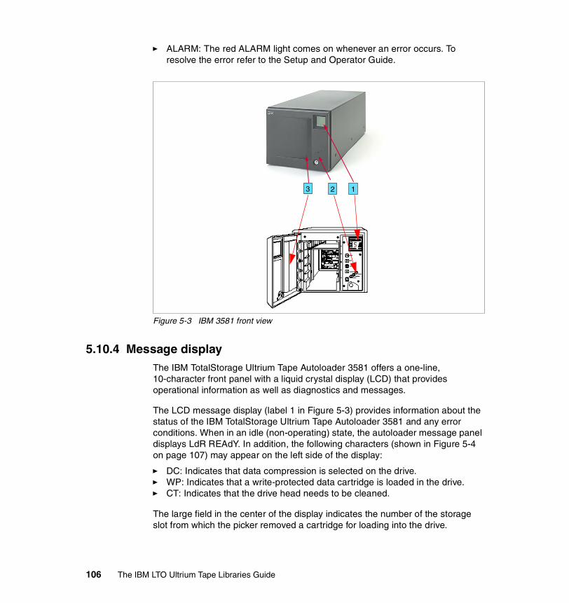
� ALARM: The red ALARM light comes on whenever an error occurs. To resolve the error refer to the Setup and Operator Guide.
Figure 5-3 IBM 3581 front view
5.10.4 Message displayThe IBM TotalStorage Ultrium Tape Autoloader 3581 offers a one-line, 10-character front panel with a liquid crystal display (LCD) that provides operational information as well as diagnostics and messages.
The LCD message display (label 1 in Figure 5-3) provides information about the status of the IBM TotalStorage Ultrium Tape Autoloader 3581 and any error conditions. When in an idle (non-operating) state, the autoloader message panel displays LdR REAdY. In addition, the following characters (shown in Figure 5-4 on page 107) may appear on the left side of the display:
� DC: Indicates that data compression is selected on the drive. � WP: Indicates that a write-protected data cartridge is loaded in the drive.� CT: Indicates that the drive head needs to be cleaned.
The large field in the center of the display indicates the number of the storage slot from which the picker removed a cartridge for loading into the drive.
123
106 The IBM LTO Ultrium Tape Libraries Guide

Whenever an error occurs, E displays in this field and the error message is displayed on line 1.
The activity bars on the right (in conjunction with the activity light) indicate robotic and drive activity:
� The bottom bar blinks when no activity is taking place.
� A slow interval between the bars appearing and disappearing indicates robotic activity.
� A fast interval between the bars appearing and disappearing indicates drive activity.
The seven numeric fields at the bottom of the display indicate the current cartridge inventory. Each will appear only if a cartridge is present in that storage slot, as shown in Figure 5-4.
Figure 5-4 IBM 3581 message display
5.10.5 Drive status messagesDuring operation, the IBM 3581 places messages about the drive’s status in the message display. These messages can appear:
� CLEANING: The drive is cleaning the head with the cleaning cartridge.� EJECTING: The drive is unloading the tape.� ERASING: The drive is erasing the tape.� LOADING: The drive is loading the tape.� LOCATING: The drive is locating the position on the tape.� READING: The drive is reading from the tape.� REWINDING: The drive is rewinding the tape.� WRITING: The drive is writing to the tape.
If an error occurs during operation, the IBM 3581 halts the current operation and displays an error code in the message display. The following list provides the most common errors codes and gives a description of each:
� CT FAILED: Cleaning tape failed to clean drive.� DEST FULL: The destination location was full.� DRIVE BUSY: The drive is busy and cannot unload the tape.
Chapter 5. IBM TotalStorage Ultrium Tape Autoloader 3581 107

� DRIVE FULL: The drive was full.� DRIVE PGRM: The attempt to set drive parameters failed.� DRIVE POST: The drive failed its Power-On Self Test (POST).� FRONT SLOT: A front slot sensor was not tripped.� FRONT TAPE: A front tape sensor was not tripped.� LDR INIT: The autoloader could not complete its initialization.� PCKR EMPTY: The picker was empty.� PCKR FULL: The picker was full.� REAR SLOT: A rear slot sensor was not tripped.� REAR TAPE: A rear tape sensor was not tripped.� ROBOT POST: The robotics failed its Power-On Self Test (POST).� SRC EMPTY: The source location was empty.� SLOT EMPTY: No slot beam was detected.� PWR SWITCH: The front power switch was pressed.� SLOT FULL: A cartridge was already in the slot.
This list is not complete. See the Setup and Operator Guide for the full error list.
5.10.6 Control buttonsThe control buttons are push buttons on the operator panel that let you interact with the menus on the message display (Figure 5-5 on page 109):
MODE: Scrolls through the commands that you can use to operate the IBM 3581 (label 1 in Figure 5-5 on page 109).
NEXT: Highlights the next item or value in the currently displayed menu (label 2 in Figure 5-5 on page 109)
SELECT: Selects the currently displayed operation (label 3 in Figure 5-5 on page 109).
PREVIOUS: Highlights the previous item or value in the currently displayed menu (label 4 in Figure 5-5 on page 109).
To operate a button, press and release it. You can use the control buttons to:
� Load a tape cartridge into a drive (LOAd dRV)
� Eject a tape cartridge from the drive and put it into the storage slot that it was loaded from (EJECT dRV)
� Load slot 6 from slot 1, or load slot 7 from slot 2 (LOAD SLOT)
� Move a cartridge from slot 6 to slot 1 or from slot 7 to slot 2 (EJECT SLOT)
� Eject a tape cartridge that was left in the media picker into an empty destination slot (EJECT PCKR)
� Set the SCSI ID of the autoloader or the drive (SET SCSI)
108 The IBM LTO Ultrium Tape Libraries Guide
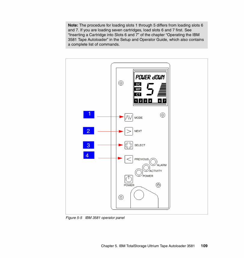
Figure 5-5 IBM 3581 operator panel
Note: The procedure for loading slots 1 through 5 differs from loading slots 6 and 7. If you are loading seven cartridges, load slots 6 and 7 first. See “Inserting a Cartridge into Slots 6 and 7” of the chapter “Operating the IBM 3581 Tape Autoloader” in the Setup and Operator Guide, which also contains a complete list of commands.
2
3
1
4
Chapter 5. IBM TotalStorage Ultrium Tape Autoloader 3581 109

5.10.7 Operating modesThe IBM 3581 operates in both random access mode (in which the server’s application software manages the cartridges) and sequential access mode (in which the autoloader’s firmware manages the cartridges).
Change between random and sequential mode through the Diagnostic Menus.
Select CHG MODE to toggle between the random access and sequential access modes. The IBM 3581 can operate in either mode:
� In random access mode, the autoloader allows the server’s application software to select any data cartridge in any order. You can logically divide cartridge usage to satisfy particular data storage needs. For example, you can assign one or more cartridges to specific data functions (such as certain directories or network servers), or you can assign specific cartridges to individual users or groups (such as Sales or Engineering).
� In sequential access mode, all cartridges present are considered to be a single volume. The autoloader’s firmware predefines the selection of the cartridges. After initialization, the firmware causes the autoloader to always load the first cartridge found (counting from 1 through 7) into the drive. After the server’s application software has filled this cartridge and unloaded the drive, the autoloader automatically returns the cartridge to its storage slot and loads the next cartridge in order. Empty storage slots are ignored. The autoloader continues this process until the volume is full.
To change the mode of operation:
1. Ensure that LdR REAdY appears on the message display.2. Press and hold the NEXT button and then the MODE button until dIAG MENU
displays (approximately 5 seconds).3. Press and hold MODE until CH MOdE appears on the message display.4. Press SELECT to display the current mode of operation.5. Press NEXT or PREVIOUS to toggle the mode between SEQUENTIAL and
RANdOM.6. Choose the mode that you want and press SELECT. CYCLE PWR blinks on
the message display. If you changed to random mode, LdR REAdY then displays; if you changed to sequential mode, SEQ REAdY then displays.
7. To activate the new mode of operation, cycle power (turn off, then on) to the IBM 3581.
The complete list of mode set-up commands is in the Operator and Setup Guide.
Note: While in sequential access mode, the autoloader’s robotics are not logically connected to the SCSI bus and do not respond to SCSI commands.
110 The IBM LTO Ultrium Tape Libraries Guide

5.11 Drive cleaning All IBM Ultrium tape drives have an integrated cleaning mechanism that brushes the head at load time and again when unloading a cartridge. There is also a cleaning procedure using a special cleaning cartridge.
The IBM 3581 internal tape drive determines when the head needs to be cleaned and alerts you by displaying CT on the message display (label 1 in Figure 5-3 on page 106). This is the only occasion when a cleaning cartridge should be used. The IBM 3581 supports three methods of cleaning the drive:
� Host cleaningHost cleaning enables the server software to detect the need to clean an Ultrium Tape Drive and to control the cleaning process. The cleaning cartridge must be stored in one of the available storage slots within the 3581.
� Automatic cleaning (AUTOCLEAN)Automatic cleaning enables the 3581 to automatically respond to any tape drive’s request for cleaning and to begin the cleaning process. Automatic cleaning makes the cleaning process transparent to any host application using the autoloader. If the server application does not support the host cleaning function, use the autoclean function.
� Manual cleaningManual cleaning requires you to select a menu option from the autoloader’s display. Manual cleaning is always supported, regardless of whether host cleaning or automatic cleaning is enabled or disabled.
In all methods, the autoloader performs the cleaning after you unload the data cartridge from the drive and before the next load.
Proper instructions for cleaning the IBM 3581 tape drive can be found in “Performing Diagnostic and Maintenance Functions” in the Setup and Operator Guide.
Attention: When cleaning the drive head, use only the IBM LTO Ultrium Cleaning Cartridge or an IBM-approved cleaning cartridge.
Note: Whenever you enable host application cleaning or the autoloader’s autoclean function, the tape capacity of the autoloader is reduced to six tapes without the barcode reader and to five cartridges with the barcode reader feature installed. The extra slot is used for storing the cleaning cartridge within the IBM 3581.
Chapter 5. IBM TotalStorage Ultrium Tape Autoloader 3581 111

5.12 Firmware upgradeEach IBM Ultrium Tape drive and library contains IBM Licensed Internal Code, often referred to as firmware. At installation time, you should make sure the latest firmware is installed on your IBM LTO Autoloader. As the IBM 3581 is designated as a Customer Setup Machine, it is the customer’s responsibility to have the current firmware installed.
Determine the latest level of firmware available from the Web site:
http://www-1.ibm.com/support/docview.wss?rs=541&context=STCVQ6N&q=ssg1*&uid=ssg1S4000042&loc=en_US&cs=utf-8&lang=en+en
Follow the instructions for updating your firmware in the IBM 3581 Ultrium Tape Autoloader Setup, Operator, and Service Guide, GA32-0412, or from:
http://ssddom02.storage.ibm.com/techsup/webnav.nsf/support/ltofaqs_updatefw_drivefw
112 The IBM LTO Ultrium Tape Libraries Guide

Chapter 6. IBM TotalStorage Ultrium Tape Library 3582
The newest member of the IBM Ultrium family is the IBM TotalStorage Ultrium Tape Library 3582, shown in Figure 6-1 on page 114. It is a high-performance, reliable, scalable tape subsystem. Designed for tape automation, the IBM TotalStorage Ultrium Tape Library 3582 (IBM 3582) can be attached to iSeries, pSeries, xseries, Intel (running Windows or Linux), Sun SPARC, Hewlett-Packard, and other open systems using SCSI or Fibre Channel attachment. It uses IBM Ultrium 2 tape drives for faster data transfer and reliability in automated library service. Each aspect of the library subsystem has been optimized for repeated, reliable unattended tape handling.
6
© Copyright IBM Corp. 2000, 2003. All rights reserved. 113

6.1 Model descriptionThe IBM 3582 tape library houses one or two IBM Ultrium 2 tape drives, which each have a native data transfer rate of 35 MBps and a cartridge capacity of 200 GB. The drives feature data compression hardware using an adaptation of the IBM LZ1 compression algorithm that provides an effective data rate of up to 70 MBps and a cartridge capacity of up to 400 GB (with 2:1 compression) on IBM Ultrium 2 media. Multiple drive models provide additional enhanced functions such as faster transfer of data, simultaneous backup, concurrent read-write operations, and fault tolerance through Control Path Failover.
The IBM 3582 has one I/O slot plus additional cartridge capacity of 23 slots (24 slots in all), allowing a native capacity of 4.8 TB of uncompressed data. With compression (assuming 2:1), the IBM 3582 can store 9.6 TB of data. These capacities assume that the I/O slot has been configured as an additional storage slot, increasing the overall library capacity.
The IBM 3582 is an excellent high-performance, entry-level choice for entry-level and midrange systems.
Figure 6-1 IBM TotalStorage Ultrium Tape Library 3582
The IBM TotalStorage Ultrium Tape Library 3582 supports three Ultrium 2 drive types: Ultrium 2 LVD, Ultrium 2 HVD, and Ultrium 2 FC. The drives can be intermixed. The IBM 3582 comes standard with multi-path architecture and the ability to partition the library into two logical libraries. The library can be configured as a stand-alone unit or mounted in an industry-standard 19-inch
114 The IBM LTO Ultrium Tape Libraries Guide

rack. Additional optional features include Control Path Failover for AIX and a Remote Management Unit/Specialist for remote library management.
Table 6-1 IBM 3582 model summary
6.1.1 Tape drivesThe IBM 3582 libraries use IBM LTO Ultrium 2 tape drives. It is mandatory to have at least one IBM Ultrium drive installed in the library. An additional drive may be added at the initial order or as a field upgrade performed by the customer.
The installed drives may be any mixture of LVD, HVD, or FC. The drives are ordered for plant or field installation using chargeable feature codes:
� Feature #8103 provides one IBM Ultrium 2 tape drive with a Low Voltage Differential (LVD) Ultra2/Wide SCSI Connection.
� Feature #8104 provides one IBM Ultrium 2 tape drive with a High Voltage Differential (HVD) Ultra/Wide SCSI Connection.
� Feature #8105 provides one IBM Ultrium 2 tape drive with a Native 2 Gb Fibre Channel Connection.
Each IBM Ultrium tape drive contains the electronics and logic for reading and writing data, control of the tape drive, management of the data buffer, and error- recovery procedures. All tape drives are packaged as a common assembly that is a Field Replaceable Unit (FRU), designed for quick removal and replacement.
6.1.2 Cartridge storageAs well as the installed tape drives, the library enclosure contains cartridge storage slots, arranged in two rows. The row toward the front of the library is made of two removable magazines of seven slots each. The row toward the rear of the library contains nine slots (Figure 6-3 on page 116). The magazines are designed so that tape cartridges can only be inserted in the proper orientation. Once inserted, the tape cartridges will be retained in the magazine so that they remain in place even when the magazine is inverted and shaken lightly. The magazines can only be inserted one way into the mounting columns in the library.
Model Cartridge slots
Data capacity (native)
Data capacity (compressed)
IBM Ultrium tape drives
3582-L23 23a
a. Plus one I/O Station slot that can be assigned as a storage slot. If this is done,the library capacity is 4.8 TB (9.6 TB compressed).
4.4 TB 8.8 TB 1-2
Chapter 6. IBM TotalStorage Ultrium Tape Library 3582 115
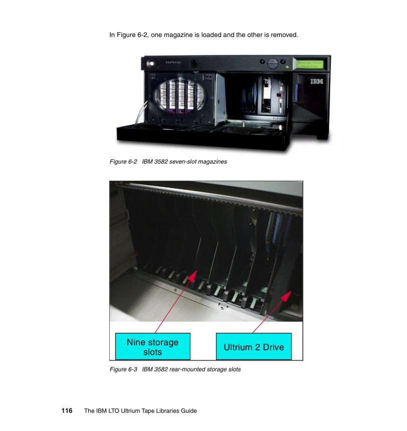
In Figure 6-2, one magazine is loaded and the other is removed.
Figure 6-2 IBM 3582 seven-slot magazines
Figure 6-3 IBM 3582 rear-mounted storage slots
Nine storage slots Ultrium 2 Drive
116 The IBM LTO Ultrium Tape Libraries Guide

6.1.3 Barcode scannerA barcode scanner is provided as standard with the IBM 3582-L23, and it does not affect the slot capacity of the libraries. The barcode scanner is used during the inventory process to locate all cartridges inserted into the library. This action is repeated every time the front door is opened to ensure that the inventory is updated if a cartridge has been manually added, moved, or removed while the door was open.
6.1.4 I/O stationThis facility enables the insertion and ejection of cartridges without interrupting the normal operation of the library. There is a single-slot I/O station where a cartridge can be inserted or ejected by opening the I/O station door.
6.1.5 Robotic systemIn conjunction with the library control microcode, the robotic system identifies and moves cartridges between the storage slots, tape drives, and the I/O station. It has a number of components:
� A cartridge picker for placing cartridges in storage slots, tape drives, or the I/O station
� A bar code scanner used to set up the library initially when it identifies the types of storage arrays and tape drives installed in the library, and in normal operation for reading the external labels on the cartridges, when it locates and categorizes all cartridges installed in the library
� X-axis and Z-axis drive motors for moving the picker assembly inside the library enclosure
6.1.6 Library control and operationThe library control unit contains the electronics and logic for autochanger operations. It controls all operations in the IBM 3582 library, including the interaction between the library and operators. The control unit Licensed Internal Code creates and maintains the library configuration, the physical location of the robotic system, and the inventory of cartridges. The database is kept in the flash memory of the library control hardware.
Requests issued from the server result in cartridge movement in the library. The primary requests issued are for mounting and dismounting cartridges to and from the tape drives and for inserting and ejecting cartridges. The host has records of the physical location of a cartridge in the library, and the physical location is also managed by the library.
Chapter 6. IBM TotalStorage Ultrium Tape Library 3582 117
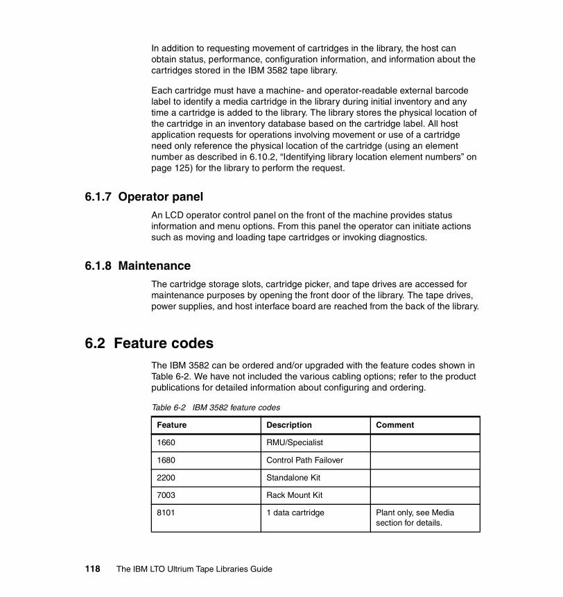
In addition to requesting movement of cartridges in the library, the host can obtain status, performance, configuration information, and information about the cartridges stored in the IBM 3582 tape library.
Each cartridge must have a machine- and operator-readable external barcode label to identify a media cartridge in the library during initial inventory and any time a cartridge is added to the library. The library stores the physical location of the cartridge in an inventory database based on the cartridge label. All host application requests for operations involving movement or use of a cartridge need only reference the physical location of the cartridge (using an element number as described in 6.10.2, “Identifying library location element numbers” on page 125) for the library to perform the request.
6.1.7 Operator panelAn LCD operator control panel on the front of the machine provides status information and menu options. From this panel the operator can initiate actions such as moving and loading tape cartridges or invoking diagnostics.
6.1.8 MaintenanceThe cartridge storage slots, cartridge picker, and tape drives are accessed for maintenance purposes by opening the front door of the library. The tape drives, power supplies, and host interface board are reached from the back of the library.
6.2 Feature codesThe IBM 3582 can be ordered and/or upgraded with the feature codes shown in Table 6-2. We have not included the various cabling options; refer to the product publications for detailed information about configuring and ordering.
Table 6-2 IBM 3582 feature codes
Feature Description Comment
1660 RMU/Specialist
1680 Control Path Failover
2200 Standalone Kit
7003 Rack Mount Kit
8101 1 data cartridge Plant only, see Media section for details.
118 The IBM LTO Ultrium Tape Libraries Guide

6.3 Physical attachmentsThe IBM 3582 tape library can be attached to IBM iSeries, IBM pSeries, IBM RS/6000 and SP systems, IBM xSeries and non-IBM servers, workstations, and personal computers that support the Ultra/Wide SCSI HVD, Ultra2/Wide SCSI LVD, and Fibre Channel interface.
SCSI cables and appropriate interposers, as required, should be ordered for attachment to a server. A power cord feature code also should be specified.
The IBM 3582 may be compatible with other servers, operating systems, and SCSI adapters. Contact your local IBM representative for a current list of supported open system configuration and software vendors, or go to:
http://www.storage.ibm.com/tape/lto/3582/3582opn.pdf
8002 1 cleaning cartridge Plant only, see section Media for details.
8103 Ultrium 2 LVD drive
8104 Ultrium 2 HVD drive
8105 Ultrium 2 Native FC drive
8203 CSU Ultrium 2 LVD drive Customer Setup
8204 CSU Ultrium 2 HVD drive Customer Setup
8205 CSU Ultrium 2 Native FC drive
Customer Setup
8110 20 data cartridges
9210 Attached to HP-UX
9211 Attached to Sun
9212 Attached to Windows
9213 Attached to other non-IBM
9215 Attached to Linux
9400 Attached to AS/400
9600 Attached to AIX
Feature Description Comment
Chapter 6. IBM TotalStorage Ultrium Tape Library 3582 119

6.4 SCSI cablingA SCSI cable is required for each library connection to a SCSI bus. If no cable is available, one should be specified on the initial order for each library or drive. A SCSI terminator is included with each cable. An interposer (a connector that matches the pin pattern of the host adapter to the pin pattern of the cable) also may be required for attachment to particular server adapters.
6.4.1 CablesA host-to-library SCSI cable is available as no-charge feature #9704 or #9705 specified only with the initial IBM 3582 order. One of these cables is supplied with each library ordered. Features #9704 and #9705 cannot be ordered as a miscellaneous equipment specification (MES) for later installation; however, the same cables may be ordered as chargeable MES upgrades after installation by using feature codes #5305 and #5604. Feature #9704 supplies a 4.5 m SCSI cable with an HD68 connector at one end and a VHDCI connector at the other end; feature #9705 supplies a 5 m SCSI cable with HD68 connectors at each end.
Additional SCSI cables are available as optional features on the IBM 3583 for LVD and HVD attachment to host adapters:
� Feature #5302, 2.5 m (8.2 feet) SCSI cable� Feature #5303, 0.7 m (2.3 feet) SCSI cable� Feature #5305, 5 m (16.5 feet) SCSI cable� Feature #5310, 10 m (33 feet) SCSI cable� Feature #5318, 18 m (60 feet) SCSI cable� Feature #5325, 25 m (82 feet) SCSI cable
The cables can be used with an HVD Ultra SCSI bus or LVD Ultra2 SCSI bus and have an HD68 connector on each end. A SCSI terminator is included with each Ultrium library.
The following cables differ in that they have a VHDCI connector at one end:
� Feature #5602, 2.5 m (8.2 feet) SCSI cable� Feature #5604, 4.5 m (14.5 feet) SCSI cable� Feature #5610, 10 m (33 feet) SCSI cable� Feature #5620, 20 m (66 feet) SCSI cable� Feature #5625, 25 m (82 feet) SCSI cable
120 The IBM LTO Ultrium Tape Libraries Guide
6.4.2 InterposersAn interposer is required to connect host adapters that do not have HD68 connectors to the SCSI cables. The following chargeable interposers are available:
� Feature #2895 interposer to connect iSeries to adapter #6501
� Feature #5099 interposer to connect a mini-68-pin VHDCI connector to the 68-pin HD68 connector on the SCSI cable.
This interposer (a 0.3m cable) has a male mini-68-pin VHDCI connector on one end and a female 68-pin HD68 connector on the other.
6.4.3 SCSI length limitationsThe overall LVD SCSI cable length is limited to 25 m (81 feet) using point-to-point interconnection. If using multi-drop interconnection, then the overall LVD SCSI cable length is limited to 12 m (39 feet). The stub length at each device must not exceed 0.1 m (0.33 feet).
The overall HVD SCSI cable lengths are limited to 25 m (81 feet) using point- to-point or multi-drop interconnection. The stub length at each device must not exceed 0.2 m (0.66 feet).
6.5 Environmental specificationsThe IBM TotalStorage Ultrium Tape Library 3582 is a stand-alone, medium-sized library unit that can be placed on a desk or in a rack.
The IBM 3582 has one or two drives and 23 cartridge slots, plus a single-slot I/O station. The physical dimensions are:
� Width: 45.5 cm (17.9 in)� Depth: 65.4 cm (25.8 in)� Height: 19.3 cm (7.7 in) for a stand-alone library on casters� Maximum weight: 30.3 kg (66.7 lb) with two drives� Four EIA units high (if rack-mounted)
6.6 Host platforms and device driversThe following no-charge codes indicate the server platform to which the IBM 3582 is attached:
� Feature #9210 attached to HP-UX
Chapter 6. IBM TotalStorage Ultrium Tape Library 3582 121

� Feature #9211, attached to Sun system� Feature #9212, attached to Windows NT or Windows 2000 system� Feature #9213, attached to other non-IBM system� Feature #9215, attached to Linux system� Feature #9400, attached to iSeries system� Feature #9600, attached to xSeries
A device driver is additional code on the host server platform that enables it to recognize and talk to a peripheral device (in this case, the IBM 3582). Sometimes the driver code is supplied as part of the operating system code (such as in OS/400), sometimes a software patch is required, and sometimes the driver is installed separately from a CD or diskette (either an OS CD or provided with a vendor application).
The library is shipped with the device drivers to support the following operating environments at the minimal levels shown:
� AIX Versions 4.3.3 or later� Sun Solaris 2.6, Solaris 7, or 8� Windows NT 4.0 with Service Pack 6� Windows 2000 (9215)� Windows 2003� HP-UX 11.0, 11.i (64 bit)� OS/400 V5R1 or later� Linux Red Hat 7.2 (32 and 64 bit kernels), Red Hat 7.3, Red Hat Advanced
Server 2.1, SuSE Linux Enterprise Server Update
6.6.1 Device driver installationInstall the IBM device drivers for the IBM 3582 as follows:
� If you intend to use the IBM 3582 with a commercial software application (such as IBM Tivoli Storage Manager, VERITAS Backup Exec, or Legato NetWorker), refer to that application’s installation instructions to install the device driver and configure the IBM 3582.
� If you do not intend to use the IBM 3582 with a commercial software application, install the tape and medium device driver from the CD that is shipped with the drive. Refer to the installation instructions in the IBM SCSI
Tip: The device driver CD or diskette that is shipped with the IBM 3582 may not contain the device drivers with the most recent level or the device drivers for all supported systems. Always check the following FTP site for the latest device drivers:
ftp://ftp.software.ibm.com/storage/devdrvr/
122 The IBM LTO Ultrium Tape Libraries Guide

Tape Drive, Medium Changer, and Library Device Drivers Installation and User’s Guide GC35-0154, which is supplied on the CD with the driver code.
6.7 Storage applicationsThe software for managing the IBM 3582 is not provided with the library. It is not really feasible to use the IBM 3582 without some additional application software to manage the slots and cartridge inventory. Additional software support is available through library management software products, which can be obtained separately from IBM, IBM Business Partners, or independent software providers. A list of compatible software is available at the Web site:
http://www.storage.ibm.com/hardsoft/tape/conntrix/pdf/lto_isv_matrix.pdf
You will find details for each application including Ultrium 1/2 support and specific Ultrium models and attachment methods. Contact your storage application vendor for more-detailed information about specific versions and platforms supported.
6.8 MediaOne Ultrium cleaning cartridge and one Ultrium data cartridge are included with each 3582 drive order1. With the initial order, additional data and cleaning cartridges may be ordered as chargeable features for the IBM 3582:
� Feature #8101 provides a single 200 GB Ultrium 2 Data Cartridge.Up to 19 #8101 features can be ordered. The cartridges come with a barcode label but it is not affixed.
� Feature #8002 provides a single Ultrium Cleaning Cartridge.It is a chargeable feature, and a maximum of three can be ordered.
� Feature #8110 provides a pack of twenty 200 GB Ultrium Data Cartridges with un-attached barcode labels.
Note: If you use the IBM 3582 with a commercial software application, IBM recommends that you install any IBM-supplied device driver only if instructed to do so in the installation instructions supplied by the vendor of the application. Otherwise, if the application supplies its own driver code, then conflicts could occur over which driver controls the drive. Many examples of using the Ultrium drives are given in the Redbooks Implementing IBM LTO in Linux and Windows, SG24-6268, and Using IBM LTO Ultrium with Open Systems, SG24-6502.
1 All media and cleaning cartridges are warranted separately from the IBM 3582.
Chapter 6. IBM TotalStorage Ultrium Tape Library 3582 123

Subsequent to the initial order, additional supplies may be ordered from the IBM media business or a third-party media vendor. Refer to Appendix A, “LTO Ultrium tape media” on page 223 for details about ordering supplies and cartridges, with or without labels.
6.9 Installation and performance considerationsiSeries configurations allow only one drive per input/output port for maximum performance. Installing more than one Ultrium tape library on an input/output port may affect drive performance.
Installing more than one Ultrium drive on a SCSI bus may affect tape drive performance. For optimal performance, it is recommended that no more than one IBM Ultrium drive be attached to an individual SCSI bus.
Intermixing of other SCSI devices on the same SCSI bus as the IBM 3582 Ultrium tape library may affect performance of those devices.
While IBM Ultrium tape drives provide the capability for high tape performance, other components of the system may limit the actual performance achieved. The compression technology used in the tape drive can typically double the amount of data that can be stored on the media; however, the actual degree of compression achieved is highly sensitive to the characteristics of the data being compressed.
The IBM 3582 Ultrium tape library has multi-path architecture; see 2.6, “Multi-path architecture” on page 46 for more information. This means the library can be logically divided into two separate physical libraries with a drive each, a seven-slot magazine each, and a pre-determined number of slots in the rear storage area of the IBM 3582. If the I/O slot is defined it can be shared.
6.10 IBM 3582 initial set-upThe following section covers some of the major items required to implement, manage, and operate the IBM 3582 tape library. It does not cover all tasks and we do not intend to cover all of the specific commands. For more details, refer to the IBM 3582 Ultrium Tape Library Setup, Operator, and Service Guide, GA32-0548.
124 The IBM LTO Ultrium Tape Libraries Guide
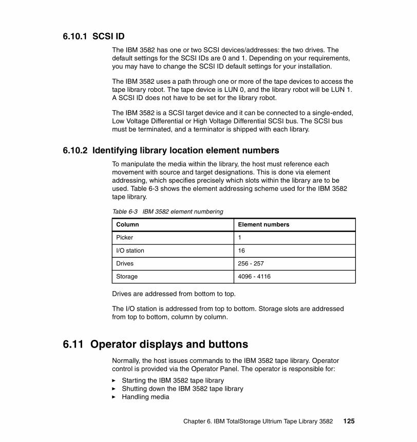
6.10.1 SCSI IDThe IBM 3582 has one or two SCSI devices/addresses: the two drives. The default settings for the SCSI IDs are 0 and 1. Depending on your requirements, you may have to change the SCSI ID default settings for your installation.
The IBM 3582 uses a path through one or more of the tape devices to access the tape library robot. The tape device is LUN 0, and the library robot will be LUN 1. A SCSI ID does not have to be set for the library robot.
The IBM 3582 is a SCSI target device and it can be connected to a single-ended, Low Voltage Differential or High Voltage Differential SCSI bus. The SCSI bus must be terminated, and a terminator is shipped with each library.
6.10.2 Identifying library location element numbersTo manipulate the media within the library, the host must reference each movement with source and target designations. This is done via element addressing, which specifies precisely which slots within the library are to be used. Table 6-3 shows the element addressing scheme used for the IBM 3582 tape library.
Table 6-3 IBM 3582 element numbering
Drives are addressed from bottom to top.
The I/O station is addressed from top to bottom. Storage slots are addressed from top to bottom, column by column.
6.11 Operator displays and buttonsNormally, the host issues commands to the IBM 3582 tape library. Operator control is provided via the Operator Panel. The operator is responsible for:
� Starting the IBM 3582 tape library� Shutting down the IBM 3582 tape library� Handling media
Column Element numbers
Picker 1
I/O station 16
Drives 256 - 257
Storage 4096 - 4116
Chapter 6. IBM TotalStorage Ultrium Tape Library 3582 125
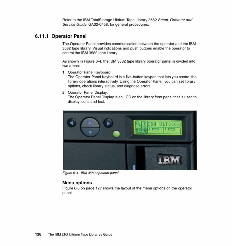
Refer to the IBM TotalStorage Ultrium Tape Library 3582 Setup, Operator and Service Guide, GA32-0458, for general procedures.
6.11.1 Operator PanelThe Operator Panel provides communication between the operator and the IBM 3582 tape library. Visual indications and push buttons enable the operator to control the IBM 3582 tape library.
As shown in Figure 6-4, the IBM 3582 tape library operator panel is divided into two areas:
1. Operator Panel Keyboard: The Operator Panel Keyboard is a five-button keypad that lets you control the library operations interactively. Using the Operator Panel, you can set library options, check library status, and diagnose errors.
2. Operator Panel Display: The Operator Panel Display is an LCD on the library front panel that is used to display icons and text.
Figure 6-4 IBM 3582 operator panel
Menu optionsFigure 6-5 on page 127 shows the layout of the menu options on the operator panel.
126 The IBM LTO Ultrium Tape Libraries Guide

Figure 6-5 IBM 3582 top-level menu options
Each menu is accessible through the Operator Panel push buttons. Refer to the Operation chapter in the IBM TotalStorage Ultrium Tape Library 3582 Setup, Operator and Service Guide, GA32-0458, for all menu items.
Using commands that require an offline stateSome commands require that the library be in an offline state. If any such commands are attempted while the library is in an online state, the operator will be requested to take the library offline.
Operator intervention messageIf a problem causes an operator intervention message to appear, refer to the Troubleshooting and Diagnostics section in the IBM TotalStorage Ultrium Tape Library 3582 Setup, Operator and Service Guide, GA32-0458.
Setup Menu Tools Menu
Main Menu
Command MenuStatus Menu
Retry Counts
Inventory
Motion Counts
Sensor Status
Errors
Display FW
Serial Number
Move Media
Export
Dismount Drive
Bulk Load
Bulk Unload
Import
Sequential Model
User Interface
Config Slots
SCSI
RMU
AutoClean
Setup Wizard
Scanner
Reset Configuration
Self Test
Load Firmware
Demo Test
Drive Maintentance
Manufacturing Test
Clean Drive
Pos Picker
Output Logs
Replace Drive
Chapter 6. IBM TotalStorage Ultrium Tape Library 3582 127

6.12 Library modeThe library operates in one of two modes: random mode or sequential mode.
Sequential mode is used with applications that recognize the tape drives but not the medium changer. Tape cartridge locations and loading are managed by the library, and data is written to tapes in the order in which they are stored in the library.
Random mode is used with applications that recognize the medium changer and drives. The application manages the tape loading, slot positioning, and the order in which cartridges are used.
Libraries usually are set up using random mode.
6.13 Drive cleaning All of the IBM Ultrium Tape Drives have an integrated cleaning mechanism that brushes the head at load time and again when unloading a cartridge. Drives also have a cleaning procedure that uses a special cleaning cartridge, should this become necessary.
A specially labeled IBM LTO Ultrium Cleaning Cartridge is supplied with each IBM 3582 tape library. The drive determines when the drive head needs to be cleaned, and alerts you by displaying CT on the message display.
6.14 Firmware upgradesEach IBM Ultrium tape drive and tape library contains IBM Licensed Internal Code, often referred to as firmware. At installation time, you should make sure the current firmware is installed on your IBM LTO tape drives and library. As the IBM 3582 is designated as a Customer Setup Machine, it is the customer’s responsibility to have the current firmware installed. Determine the latest level of firmware available from the IBM Technical Support Web site:
http://ssddom02.storage.ibm.com/techsup/webnav.nsf/support/3582
Follow the instructions for updating your firmware in theIBM 3582 Ultrium Tape Library Setup, Operator, and Service Guide, GA32-0548.
Attention: When cleaning the drive head, use only the IBM LTO Ultrium Cleaning Cartridge or an IBM-approved cleaning cartridge.
128 The IBM LTO Ultrium Tape Libraries Guide

Chapter 7. IBM TotalStorage Ultrium Scalable Tape Library 3583
The fourth member of the IBM Ultrium family is the IBM TotalStorage Ultrium Scalable Tape Library 3583, shown in Figure 7-1 on page 130. It is a high-performance, reliable, scalable tape subsystem. Designed for tape automation, the IBM TotalStorage Ultrium Scalable Tape Library 3583 (IBM 3583) can be attached to iSeries, pSeries, xSeries, AS/400, RS/6000, Netfinity, and non-IBM servers, workstations, and personal computers that support SCSI HVD, SCSI LVD, and Fibre Channel interfaces. It uses IBM Ultrium tape drives for fast data transfer and reliability in automated library service. Each aspect of the library subsystem has been optimized for repeated, reliable unattended tape handling.
7
© Copyright IBM Corp. 2000, 2003. All rights reserved. 129
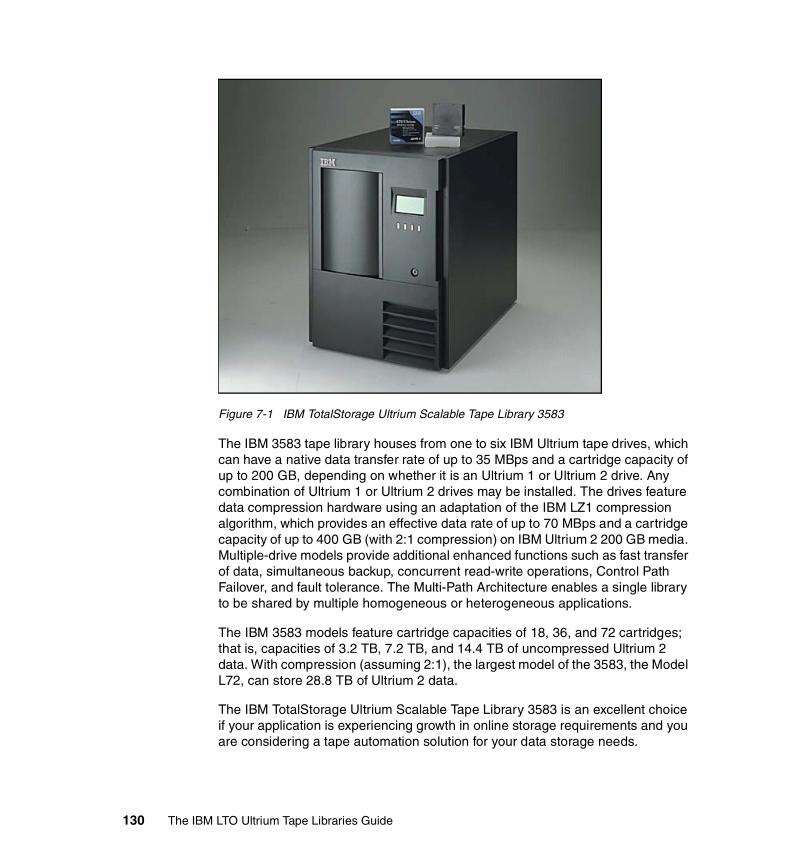
Figure 7-1 IBM TotalStorage Ultrium Scalable Tape Library 3583
The IBM 3583 tape library houses from one to six IBM Ultrium tape drives, which can have a native data transfer rate of up to 35 MBps and a cartridge capacity of up to 200 GB, depending on whether it is an Ultrium 1 or Ultrium 2 drive. Any combination of Ultrium 1 or Ultrium 2 drives may be installed. The drives feature data compression hardware using an adaptation of the IBM LZ1 compression algorithm, which provides an effective data rate of up to 70 MBps and a cartridge capacity of up to 400 GB (with 2:1 compression) on IBM Ultrium 2 200 GB media. Multiple-drive models provide additional enhanced functions such as fast transfer of data, simultaneous backup, concurrent read-write operations, Control Path Failover, and fault tolerance. The Multi-Path Architecture enables a single library to be shared by multiple homogeneous or heterogeneous applications.
The IBM 3583 models feature cartridge capacities of 18, 36, and 72 cartridges; that is, capacities of 3.2 TB, 7.2 TB, and 14.4 TB of uncompressed Ultrium 2 data. With compression (assuming 2:1), the largest model of the 3583, the Model L72, can store 28.8 TB of Ultrium 2 data.
The IBM TotalStorage Ultrium Scalable Tape Library 3583 is an excellent choice if your application is experiencing growth in online storage requirements and you are considering a tape automation solution for your data storage needs.
130 The IBM LTO Ultrium Tape Libraries Guide

7.1 Model descriptionThe IBM 3583 supports up to six IBM LTO Ultrium tape drives. It comes standard with remote library management, multi-path architecture, and the ability to partition the library into three logical libraries. The library can be configured as a stand-alone unit or can be mounted in an industry-standard 19-inch rack. Additional optional features include Control Path Failover for AIX. The Library 3583 comes in three different models. The major difference between the models is the number of storage cells shipped with the initial order:
� IBM 3583 Model L18 is supplied with space for 18 cartridges.� IBM 3583 Model L36 is supplied with space for 36 cartridges.� IBM 3583 Model L72 is supplied with space for 72 cartridges.
The models are summarized in Table 7-1:
Table 7-1 IBM 3583 model summary
The model numbering is an indication of how many cartridge slots the model was originally shipped with. However, all of the IBM 3583 models are the same physical size, and the two smaller models, L18 and L36, can be field-upgraded to hold up to 72 cartridges by the addition of upgrade features. The effect of these upgrades is shown in Table 7-3 on page 142.
7.1.1 Tape drivesThe IBM 3583 libraries support the IBM LTO Ultrium 2 tape drives as well as the Ultrium 1 tape drives. Both types of tape drives and cartridges can be resident in the same 3583 frame. It is mandatory to have at least one IBM Ultrium drive installed in any of the libraries. Up to five more drives may be added either on the initial order or as field upgrades.
The installed drives may be any mixture of LVD, HVD, or 2 Gbps switched fabric Fibre Channel attached up to a total of six. However, LVD, and HVD interfaces
Model Cartridge Slots
Native Data Capacity with Ultrium 1
Native Data Capacity with Ultrium 2
IBM Ultrium Tape Drives
L18 18a
a. Plus one I/O Station slot
1.8 TB 3.6 TB 1-6
L36 36b
b. Plus one I/O Station slot
3.6 TB 7.2 TB 1-6
L72 72c
c. Including twelve I/O Station slots
7.2 TB 14.4 TB 1-6
Chapter 7. IBM TotalStorage Ultrium Scalable Tape Library 3583 131

cannot be connected on the same SCSI bus. The drives are ordered for plant or field installation using chargeable feature codes:
� Feature #8003 provides one IBM Ultrium 1 tape drive with a Low Voltage Differential (LVD) Ultra2/Wide SCSI adapter.
� Feature #8004 provides one IBM Ultrium 1 tape drive with a High Voltage Differential (HVD) Ultra/Wide SCSI adapter.
� Feature #8103 provides one IBM Ultrium 2 tape drive with a Low Voltage Differential (LVD) Ultra160 SCSI interface.
� Feature #8104 provides one IBM Ultrium 2 tape drive with a High Voltage Differential (HVD) Ultra/Wide SCSI interface.
� Feature #8105 provides one IBM Ultrium 2 tape drive with a Fibre Channel Interface.
Each IBM Ultrium tape drive contains the electronics and logic for reading and writing of data, control of the tape drive, management of the data buffer, and error recovery procedures. All tape drives are packaged as a common assembly that is a Field Replaceable Unit (FRU), designed for quick removal and replacement. The cartridge capacities are unaffected by the number of drives installed.
7.1.2 Cartridge storageAs well as the installed tape drives, the library enclosure contains cartridge storage slots that are arranged in columns (from one to three depending on the library model). Each of the three storage columns has provision for an additional fixed slot located at the top of each column. This slot is reserved for future use.
The tape cartridges are stored in removable magazines, which are installed into the columns in the library (three magazines to each column). The magazines are designed so that tape cartridges can only be inserted in the proper orientation. Once inserted, the tape cartridges will be retained in the magazine so that they remain in place even when the magazine is inverted and shaken lightly. The magazines can only be inserted one way into the mounting columns in the library.
7.1.3 Barcode readerA barcode reader is provided as standard with all IBM 3583 models, and it does not affect the slot capacity of the libraries. The barcode reader is used during the inventory process to locate all cartridges inserted in the library. This action is repeated every time the front door is opened to ensure that the inventory is updated, should a cartridge have been manually added, moved, or removed while the door was open.
132 The IBM LTO Ultrium Tape Libraries Guide

7.1.4 I/O stationThis facility allows the insertion and ejection of cartridges without interrupting the normal operation of the library. There are two types of I/O station:
� The single-cartridge station, where the cartridge can be inserted or ejected by opening the I/O station door
� The 12-cartridge station, where 12 cartridges are contained in two removable magazines that can be inserted or ejected by opening the I/O station door
Models L18 and L36 have the single-cartridge I/O station for tape cartridges and can be upgraded to a 12-cartridge station by the feature #8012. The model L72 has the 12-cartridge station installed as standard equipment.
7.1.5 Robotic systemIn conjunction with the library control microcode, the robotic system identifies and moves cartridges between the storage slots, tape drives, and the I/O station. It has a number of components:
� A cartridge picker for placing cartridges in storage slots, tape drives, or the I/O station
� A barcode reader used to set up the library initially when it identifies the types of storage arrays and tape drives installed in the library, and in normal operation for reading the external labels on the cartridges, when it locates and categorizes all cartridges installed in the library
� A picker assembly for mounting the cartridge picker and the bar code scanner
� Y-axis and Z-axis drive motors for rotating the picker assembly, and moving it vertically, inside the library enclosure
7.1.6 Library control and operationThe library control unit contains the electronics and logic for autochanger operations. It controls all operations in the IBM 3583 libraries, including the interaction between the library and operators. The control unit Licensed Internal Code creates and maintains the library configuration, the physical location of the robotic system, and the inventory of cartridges. The database is kept in the flash memory of the library control hardware.
Requests issued from the server result in cartridge movement in the library. The primary requests issued are for mounting and dismounting cartridges to and from the tape drives and for inserting and ejecting cartridges. The host has records of the physical location of a cartridge in the library, and the physical location is also managed by the library.
Chapter 7. IBM TotalStorage Ultrium Scalable Tape Library 3583 133
In addition to requesting movement of cartridges in the library, the host can obtain status, performance, configuration information, and information about the cartridges stored in the IBM 3583 tape library.
Each cartridge must have a machine- and operator-readable external barcode label to identify a media cartridge in the library during initial inventory and any time a cartridge is added to the library. The library stores the physical location of the cartridge in an inventory database based on the cartridge label. All host application requests for operations involving movement or use of a cartridge need only reference the physical location of the cartridge (using an element number as described in 7.11.3, “Element numbers” on page 150) for the library to perform the request.
7.1.7 Operator panelAn LCD operator control panel on the front of the machine provides status information and menu options. From this panel the operator can initiate actions such as moving and loading tape cartridges or invoking diagnostics.
7.1.8 Remote Management UnitThe Remote Management Unit (RMU) feature provides connectivity to Ethernet 10/100 LAN systems including Simple Network Management Protocol (SNMP). It allows library control, and configuration from authorized network attached consoles via a Web browser.
7.1.9 Library partitioningThe IBM 3583 library multi-path architecture (see 2.6, “Multi-path architecture” on page 46 for more information) allows homogeneous or heterogeneous open systems hosts to share the library’s robotics without storage management middleware or a dedicated server acting as a library manager.
The library can be partitioned into as many as three logical libraries in order to share the library between different software platforms and applications (such as Windows 2000 and UNIX). Partitioning in this way means that they are able to share the library robotics independently of each other. Each logical library has its own distinct drives, cartridge storage slots, and control paths. If the application supports it, both Ultrium 1 and Ultrium 2 drives and media are allowed in the same logical library. Cartridges under library control are not shared between logical libraries, nor allowed to be moved between logical libraries. Input/output (I/O) slots are shared on a first-come-first-served basis.
134 The IBM LTO Ultrium Tape Libraries Guide

For more information about the multi-path and partitioning capabilities of the IBM 3583 tape library refer to the library partitioning sections in these Redbooks:
� Using IBM LTO Ultrium with Open Systems, SG24-6502� Implementing IBM LTO in Linux and Windows, SG24-6268
7.1.10 Multiple control pathsIn addition to creating multiple logical libraries, you can also configure any logical library to have more than one control path. When you configure additional control paths, additional library sharing configurations and availability options are made possible. Access to the logical library is on a first-come, first-served basis, and each control path for a logical library can accept commands while the library is in use by another control path. By default, each logical library control path is available to servers through logical unit number 1 (LUN 1) of the first drive that is defined within that logical library.
The IBM 3583 offers an optional control path failover feature that enables the host device driver to resend the command to an alternate control path; for example, to LUN 1 of the second drive in the same logical library. With control path failover installed, the alternate control path can include another HBA, SAN, or library control path drive. The device driver initiates error recovery and continues the operation on the alternate control path without interrupting the application. Only AIX hosts are currently supported for this feature.
7.1.11 SAN Data Gateway ModuleThe SAN Data Gateway Module (feature #8005) functions as an interface between LVD SCSI Ultrium 1 tape drives (#8003) in the library and Fibre Channel devices on the SAN. It provides attachment support for Fibre Channel interfaces using a Shortwave Gigabit Interface Convertor (GBIC) with SC connectors. The SAN Data Gateway Module is manageable over the IP network. It has an Ethernet 10/100 interface with an RJ-45 connector.
7.1.12 MaintenanceThe cartridge storage slots, cartridge picker, and tape drives are accessed for maintenance purposes by opening the front door of the library. The tape drives,
Note: A logical unit number (LUN) is a number used by a server to identify a drive. The LUN for the Sequential Access device is always LUN 0 of the drive, and the LUN for the Medium Changer device is always LUN 1. All other LUNs are invalid addresses.
Chapter 7. IBM TotalStorage Ultrium Scalable Tape Library 3583 135
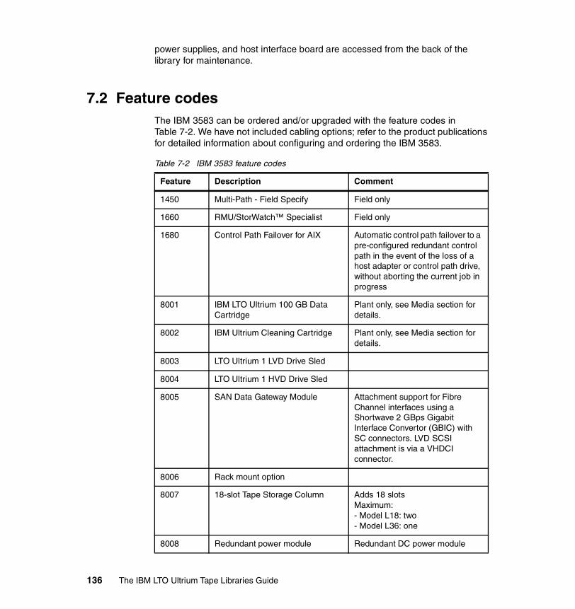
power supplies, and host interface board are accessed from the back of the library for maintenance.
7.2 Feature codesThe IBM 3583 can be ordered and/or upgraded with the feature codes in Table 7-2. We have not included cabling options; refer to the product publications for detailed information about configuring and ordering the IBM 3583.
Table 7-2 IBM 3583 feature codes
Feature Description Comment
1450 Multi-Path - Field Specify Field only
1660 RMU/StorWatch™ Specialist Field only
1680 Control Path Failover for AIX Automatic control path failover to a pre-configured redundant control path in the event of the loss of a host adapter or control path drive, without aborting the current job in progress
8001 IBM LTO Ultrium 100 GB Data Cartridge
Plant only, see Media section for details.
8002 IBM Ultrium Cleaning Cartridge Plant only, see Media section for details.
8003 LTO Ultrium 1 LVD Drive Sled
8004 LTO Ultrium 1 HVD Drive Sled
8005 SAN Data Gateway Module Attachment support for Fibre Channel interfaces using a Shortwave 2 GBps Gigabit Interface Convertor (GBIC) with SC connectors. LVD SCSI attachment is via a VHDCI connector.
8006 Rack mount option
8007 18-slot Tape Storage Column Adds 18 slotsMaximum:- Model L18: two- Model L36: one
8008 Redundant power module Redundant DC power module
136 The IBM LTO Ultrium Tape Libraries Guide

7.3 Physical attachmentsIn each of the different IBM 3583 tape library models, the interface (LVD, HVD, or Fibre Channel) on each of the drives is chosen by selecting the appropriate drive type (indicated by feature code numbers: #8003 for an LVD Ultrium 1 drive, #8004 for an HVD Ultrium 1 drive, #8103 for an LVD Ultrium 2 drive, #8104 for an HVD Ultrium 2 drive, and #8105 for a FC Ultrium 2 drive).
8010 20-pack of IBM LTO Ultrium 100 GB Data Cartridges
8012 12-cartridge I/O station Adds 18 slots in the door (12 of them can be used for non-disruptive exchange of cartridges)Maximum:- for L18 and L32: one- standard on L72
8013 6-cartridge magazine Plant only
8101 IBM LTO Ultrium 200 GB Data Cartridge
Plant only, see Media section for details.
8103 LTO Ultrium 2 LVD Drive Sled
8104 LTO Ultrium 2 HVD Drive Sled
8105 LTO Ultrium 2 Fibre Drive Sled
8110 20-pack of IBM LTO Ultrium 200 GB Data Cartridges
Plant only, see Media section for details.
9210 Attached to HP-UX
9211 Attached to Sun
9212 Attached to Windows
9213 Attached to other non-IBM
9215 Attached to Linux System
9400 Attached to AS/400
9450 Multi-Path - Plant Specify Plant only
9600 Attached to AIX
Feature Description Comment
Chapter 7. IBM TotalStorage Ultrium Scalable Tape Library 3583 137

The IBM 3583 tape library can be attached to the iSeries, pSeries, xSeries, AS/400, RS/6000, RS/6000 SP systems, Netfinity and non-IBM servers, workstations, and personal computers that support the Ultra/Wide SCSI HVD, Ultra2/Wide SCSI LVD, and Fibre Channel interface.
SCSI or FC cables and appropriate interposers, as required, should be ordered for attachment to a server. A power cord feature code should also be specified.
The IBM 3583 may be compatible with other servers, operating systems, and adapters. Contact your local IBM representative for a current list of supported configurations. You may also refer to the Interoperability Matrix (List of Supported Servers) on this Web site:
http://www.storage.ibm.com/tape/lto/3583/3583opn.pdf
Another resource is the IBM SSG HBA & SAN Interoperability Matrix on:
http://ssddom02.storage.ibm.com/hba/hba_support.pdf
7.4 CablingCables are required to attach tape drives in the IBM 3583 to each server connection (up to the number of tape drives installed).
An interposer also may be required for attachment to various server adapters. One or more of the following Fibre Channel or SCSI cables should be specified on the IBM 3583.
7.4.1 Fibre Channel cablesA Fibre Channel cable is required to attach an IBM 3583 with the San Data Gateway Module feature (#8005) or the Fibre Drive feature (#8105) to host Fibre Channel adapters, switches, or other Fibre Channel components. The short-wave, multimode GBICs that are installed in the San Data Gateway Module are SC Duplex connectors.
Note: When feature #8005 is ordered as a plant feature, one of the no-charge features #9706 (5 m SC-SC Fibre Channel cable) or #9707 (7 m LC-SC Fibre Channel cable) can be selected to provide the fiber optic cable needed to connect to the host Fibre Channel adapter. When feature #8005 is ordered as an MES feature, one of the cables listed below should be ordered if needed.
138 The IBM LTO Ultrium Tape Libraries Guide
The IBM LTO Ultrium 2 Fibre Tape Drive (#8105) comes with an LC Duplex connector. One 2 m LC-LC Fibre Channel drive-to-patch panel cable is included with each Fibre Drive feature (#8105).
Additional FC cables are available as optional features on the IBM 3583 for Fibre Channel attachment to host Fibre Channel adapters, Fibre Channel switches, or other Fibre Channel components:
� Feature #5907 - 7 m SC-LC Fibre Channel Cable� Feature #5913 - 13 m SC-LC Fibre Channel Cable� Feature #5922 - 22 m SC-LC Fibre Channel Cable� Feature #5961 - 61 m SC-LC Fibre Channel Cable� Feature #6005 - 5 m LC-LC Fibre Channel Cable� Feature #6013 - 13 m LC-LC Fibre Channel Cable� Feature #6025 - 25 m LC-LC Fibre Channel Cable� Feature #6061 - 61 m LC-LC Fibre Channel Cable
7.4.2 SCSI cablesA host-to-library SCSI cable is available as no-charge feature #9704 or #9705 only with the initial IBM 3583 order. One of these cables is supplied with each library ordered. Features #9704 and #9705 cannot be ordered later as an MES; however, the same cables can be ordered after installation as chargeable MES upgrades by using feature codes #5305 and #5604. Feature #9704 supplies a 4.5 m SCSI cable with an HD68 connector at one end and a VHDCI connector at the other end; feature #9705 supplies a 5 m SCSI cable with HD68 connectors at each end.
Additional SCSI cables are available as optional features for LVD and HVD attachment to host adapters. These cables have HD68 connectors on both ends:
� Feature #5302, 2.5 m (8.2 feet) SCSI cable� Feature #5303, 0.7 m (2.3 feet) SCSI cable� Feature #5305, 5 m (16.5 feet) SCSI cable� Feature #5310, 10 m (33 feet) SCSI cable� Feature #5318, 18 m (60 feet) SCSI cable� Feature #5325, 25 m (82 feet) SCSI cable
The following cables differ in that they have a VHDCI connector at one end:
� Feature #5602, 2.5 m (8.2 feet) SCSI cable� Feature #5604, 4.5 m (14.5 feet) SCSI cable� Feature #5610, 10 m (33 feet) SCSI cable� Feature #5620, 20 m (66 feet) SCSI cable� Feature #5625, 25 m (82 feet) SCSI cable
Chapter 7. IBM TotalStorage Ultrium Scalable Tape Library 3583 139

One SCSI differential terminator and 0.5 meter drive-to-drive cable is included with each SCSI drive feature (#8003, #8004, #8103 and #8104).
7.4.3 InterposersAn interposer is required to connect host adapters that do not have HD68 connectors to the SCSI cables. The following chargeable interposers are available:
� Feature #2895 interposer to connect iSeries and AS/400 to adapter #6501.
� Feature #5099 interposer to connect a mini-68-pin VHDCI connector to the 68-pin HD68 connector on the SCSI cable. This interposer (a 0.3 m cable) has a male mini-68-pin VHDCI connector on one end and a female 68-pin HD68 connector on the other.
7.4.4 TerminatorAn inline terminator is required when attaching the 3583 library to Hewlett-Packard V-Class systems with adapter A4800A.
The following inline terminator is available:
� Feature #5098, Inline HVD SCSI Terminator
7.4.5 Cable length limitationsThe native Fibre Channel drive and the San Data Gateway Module are capable of 2 Gbps speed. They automatically switch to a 1 Gbps speed if they are attached to a 1 Gbps host Fibre Channel adapter, switch, or other Fibre Channel components. With 1 Gbps speed the maximum cable length is limited to 300 m (984 feet), and with 1 Gbps speed to 500 m (1640 feet).
The overall LVD SCSI cable length is limited to 25 m (81 feet) using point-to-point interconnection (for example, one host connected to only one tape drive). If using multi-drop interconnection (such as one host connected to more than one tape drive on the same SCSI bus), then the overall LVD SCSI cable length is limited to 12 m (39 feet). The stub length at each device must not exceed 0.1 m (0.33 feet).
The overall HVD SCSI cable lengths are limited to 25 m (81 feet) using point- to-point or multi-drop interconnection. The stub length at each device must not exceed 0.2 m (0.66 feet).
140 The IBM LTO Ultrium Tape Libraries Guide
7.5 Upgrades and optional featuresYou can add MES features to each model type in the IBM 3583 family in order to add capacity in terms of drives and cartridge cells, and to add the 12-cartridge I/O station. This effectively takes the place of model upgrades as there are no upgrades available for the IBM 3583 series.
In other words, you cannot upgrade an IBM 3583-L18 to an IBM 3583-L36 or L72. Similarly, an IBM 3583-L36 cannot be upgraded to an IBM 3583-L72.
7.5.1 Upgrade featuresYou can expand any IBM 3583 model to the maximum capacity of the largest model (L72) with the addition of MES features.
Adding drives: You can add IBM LTO Ultrium drives to any library model to a maximum of six drives in total. The drives may be LVD, HVD, or Fibre in any combination. To install an LVD drive, add feature #8003 (Ultrium 1) or #8103 (Ultrium 2), to add an HVD drive, add #8004 (Ultrium 1) or #8104 (Ultrium 2), and to add a Fibre drive, add #8105 (Ultrium 2).
Adding cartridge capacity:You can add an additional 18 tape cartridge slots to either of the smaller IBM 3583 models using feature #8007. You can add one or two of these features to model L18 (for a total of 36 or 54 cartridge slots), and you can add one feature to model L36 (for a total of 54 cartridge slots).
You can install a 12-cartridge I/O station to models L18 and L36 by adding feature #8012. This feature accommodates the 12 cartridges in two six-slot cartridge magazines that are accessed by opening the I/O station door. In addition to the two magazines, this feature supplies six additional fixed slots in the library door for a total of 18 additional slots. This feature in combination with feature #8007 provides the maximum slot capacity and function for the two smaller IBM 3583 models.
Table 7-3 on page 142 shows how to upgrade the capacity of 3583-L18 and 3583-L36 libraries by adding extra 18-slot tape storage columns (feature #8007) and by adding the 12-cartridge I/O station (feature #8012). You may choose to set up the12-cartridge I/O station as storage slots or I/O slots.
Chapter 7. IBM TotalStorage Ultrium Scalable Tape Library 3583 141

Table 7-3 IBM 3583 capacity upgrades
7.5.2 Optional featuresTwo optional features are available:
� Feature #8006, rack mount optionThe IBM 3583 libraries can be installed either stand-alone or in a standard EIA 19-inch rack. They occupy the full width of the rack and require 14 units of rack space (24.5 in or 62.2 cm). This is the chargeable feature that provides the necessary hardware to mount the library in the rack.
� Feature #8008, redundant power moduleThis chargeable feature supplies a redundant DC power module for customers requiring an extra level of back-up protection. You can order one of these features per library.
7.6 Environmental specificationsThe IBM 3583 Scalable is a stand-alone, medium-sized library unit that can be placed on a desk or the floor.
IBM 3583 models have from one to six drives and up to 72 cartridge slots. The physical dimensions are:
� Width: 48.1 cm (18.9 in)� Depth: 73.5 cm (28.9 in)
3583 model
Extra tape storage columns
Single cartridge I/O station
12 cartridge I/O station defined as storage
12 cartridge I/O station defined as I/O
L18 0 18 storage1 I/O
36 storage0 I/O
24 storage12 I/O
L18 1 36 storage1 I/O
54 storage0 I/O
42 storage12 I/O
L18 2 54 storage1 I/O
72 storage0 I/O
60 storage12 I/O
L36 0 36 storage1 I/O
54 storage0 I/O
42 storage12 I/O
L36 1 54 storage1 I/O
72 storage0 I/O
60 storage12 I/O
L72 Not available not available 72 storage0 I/O
60 storage12 I/O
142 The IBM LTO Ultrium Tape Libraries Guide

� Height: 68.5 cm (27.0 in) for a stand-alone library on casters� Maximum weight: 116.6 kg (257 lb) with six drives and 72 cartridges
7.7 Host platforms and device driversThe following no-charge specify codes indicate the server platform to which the IBM 3583 is attached:
� Feature #9210, attached to HP-UX� Feature #9211, attached to Sun system� Feature #9212, attached to Windows NT system� Feature #9213, attached to other non-IBM system� Feature #9215, attached to Linux system (Model L23 and H23)� Feature #9400, attached to iSeries system� Feature #9600, attached to RS/6000 system
A device driver is additional code on the host server platform that enables it to recognize and talk to a peripheral device (in this case, the IBM 3583). Sometimes the driver code is supplied as part of the operating system code (for example, in OS/400), sometimes a software patch is required, and sometimes the driver is installed separately from a CD or diskette (either an OS CD or provided with a vendor application).
Ultrium 1The IBM 3583 is shipped with the device drivers to support Ultrium 1 drives in the following operating environments at the minimal levels shown:
� AIX Versions 4.3.2 or later� Sun Solaris 2.6, 7, and 8� Windows NT 4.0 with Service Pack 6� Windows 2000 build 2195 or greater� HP-UX 11.0� OS/400 V4R4
Ultrium 2The IBM 3583 is shipped with the device drivers to support Ultrium 2 drives in the following operating environments at the minimal levels shown:
� AIX Versions 4.3.3 or later� Sun Solaris 7, 8, 9� Windows NT 4.0 with Service Pack 6� Windows 2000 build 2195 or greater� Windows 2003� HP-UX 11.0, 11.i
Chapter 7. IBM TotalStorage Ultrium Scalable Tape Library 3583 143

� OS/400 V5R1 or later� Linux distributions: Linux Red Hat 7.2 32-bit and 64 bit Kernels, Linux Red Hat
7.3, Red Hat Advanced Server 2.1, SuSE Linux Enterprise Server Update
7.7.1 Device driver installationInstall the IBM device drivers for the IBM 3583 as follows:
� If you intend to use the IBM 3583 with a commercial software application (such as IBM Tivoli Storage Manager, VERITAS Backup Exec, or Legato NetWorker), refer to that application’s installation instructions to install the device driver and configure the IBM 3583.
� If you do not intend to use the IBM 3583 with a commercial software application, install the tape and medium device driver from the CD that is shipped with the drive. Refer to the installation instructions in the IBM SCSI Tape Drive, Medium Changer, and Library Device Drivers Installation and User’s Guide, GC35-0154, which is supplied on the CD with the driver code.
7.8 Storage applicationsThe software to manage the IBM 3583 is not provided with the libraries. Additional software support is available through library management software products that must be obtained separately from IBM, IBM Business Partners, or independent software vendors. A list of compatible software is available at:
http://www.storage.ibm.com/hardsoft/tape/conntrix/pdf/lto_isv_matrix.pdf
Tip: The device driver CD or diskette that is shipped with the IBM 3583 may not contain the device drivers with the most recent level or the device drivers for all supported systems. Always check the following FTP site for the latest device drivers:
ftp://ftp.software.ibm.com/storage/devdrvr/
Note: If you use the IBM 3583 with a commercial software application, IBM recommends that you install any IBM-supplied device driver only if instructed to do so in the installation instructions supplied by the vendor of the application. Otherwise, if the application supplies its own driver code, then conflicts could occur over which driver controls the drive. Many examples of using the Ultrium drives are given in the redbooks Implementing IBM LTO in Linux and Windows, SG24-6268, and Using IBM LTO Ultrium with Open Systems, SG24-6502.
144 The IBM LTO Ultrium Tape Libraries Guide

You will find details for each application including Ultrium 1 and Ultrium 2 support, and specific Ultrium models and attachment methods. You should also contact your storage application vendor for more detailed information of specific versions and platforms supported.
7.9 MediaOne Ultrium cleaning cartridge and one Ultrium data cartridge are included with each library order1. With the initial order, additional data and cleaning cartridges may be ordered as chargeable features for the IBM 3583:
� Feature #8001 provides a single 100 GB Ultrium data cartridge.It is a chargeable feature, and a maximum of 19 can be ordered.
� Feature #8002 provides a single Ultrium cleaning cartridge.It is a chargeable feature and a maximum of three can be ordered.
� Feature #8010 provides a pack of twenty 100 GB Ultrium data cartridges.It is a chargeable feature, and the maximum of one can be ordered.
� Feature #8101 provides a single 200 GB Ultrium 2 Data Cartridge.Up to 19 can be ordered. The cartridges come with a barcode label but it is not affixed.
� Feature #8110 provides a pack of twenty 200 GB Ultrium Data Cartridges with unattached barcodes labels. It is a chargeable feature, and a maximum of four can be ordered.
7.10 Installation and performance considerationsiSeries configurators allow only one drive per input/output port for maximum performance. Installing more than one Ultrium tape library on an input/output port may affect drive performance.
Installing more than one Ultrium drive on a SCSI bus may affect tape drive performance. For optimal performance, it is recommended that no more than one IBM Ultrium drive be attached to an individual SCSI bus.1 All media and cleaning cartridges are warranted separately from the IBM TotalStorage Ultrium Scalable Tape Library 3583.
Note: All of the media features are available only with the initial order. They cannot be ordered as an MES feature. After the initial order, additional supplies can be ordered from the IBM media business or a third-party media vendor. Refer to Appendix A, “LTO Ultrium tape media” on page 223 for details about ordering supplies and cartridges, with or without labels.
Chapter 7. IBM TotalStorage Ultrium Scalable Tape Library 3583 145
Intermixing of other SCSI devices on the same SCSI bus as the IBM 3583 may affect performance of those devices.
While the IBM Ultrium tape drives provide the capability for high tape performance, other components of the system may limit the actual performance achieved. The compression technology used in the tape drive can typically double the amount of data that can be stored on the media; however, the actual degree of compression achieved is highly sensitive to the characteristics of the data being compressed.
The weight of the IBM 3583, depending on the number of drives and cartridges, may be up to 257 lbs (116.6 kg). If more than one library is mounted in a rack, a tipping hazard could be created. Customers are advised to take necessary safety precautions when mounting the libraries in the racks.
7.11 IBM 3583 initial set-upThe following section covers some of the major items required to implement, manage, and operate the IBM 3583. It does not cover all tasks and we do not intend to cover all of the specific commands. For more details, refer to the IBM 3583 Ultrium Scalable Tape Library Setup and Operator Guide, GA32-0411.
7.11.1 SCSI ID and LUN assignmentThe SCSI ID and LUN assignment in the IBM 3583 tape library depends on whether the multi-path feature is installed.
If the multi-path feature is installed, the Logical Unit Number (LUN) for the tape drive is always LUN 0, and the LUN for the Medium Changer device is always LUN 1. All other LUNs are invalid addresses.
If the multi-path feature is not installed, the IBM 3583 tape library uses a separate SCSI device address for the robot so you will have to define a SCSI ID for the tape library unit. In this case the LUNs for both the library and the tapes are always LUN 0.
Note: The Medium Changer SCSI ID is the same as the SCSI ID for the first drive. You can enable additional drives to optionally provide Medium Changer (LUN 1) addressing by configuring more than one logical library or by enabling additional control paths.
146 The IBM LTO Ultrium Tape Libraries Guide

The IBM 3583 consists of up to seven SCSI devices: the library and up to six drives. The default settings for the SCSI IDs are 6 for the library and 0 through 5 for the drives. Depending on your requirements, you may need to change the SCSI ID default settings for your installation.
The IBM 3583 is a SCSI target device and can be connected to a single-ended LVD or HVD SCSI bus. Both ends of the bus must be terminated and a terminator is shipped with each library. The design of an IBM 3583 enables the SCSI type (single-ended, LVD, or HVD) to be configured at the customer site via a switch located on the SCSI Interface PCBA. Although the IBM 3583 can be attached to a wide SCSI bus, it is not a wide SCSI device and its SCSI ID must be in the range of 0 to 7.
7.11.2 Identifying library locationsThe convention shown in Table 7-4 is used to identify the coordinates of each library element (storage, slots, or drives).
Table 7-4 IBM 3583 storage slot coordinates
The columns are numbered from 1 to 5 starting from the I/O station column and continuing clockwise (see Figure 7-2 on page 148).
Note: Do not use SCSI ID F as it is reserved for internal use by the SCSI library. SCSI ID 7 is also often used by the host SCSI adapter.
First digit Second digit Third digit
Column Magazine Row
Chapter 7. IBM TotalStorage Ultrium Scalable Tape Library 3583 147

Figure 7-2 IBM 3583 storage columns: top view
The magazines within each column are designated A to C from top to bottom (label 1 in Figure 7-3 on page 149).
The rows within each magazine are numbered from 1 to 6 from top to bottom (label 2 in Figure 7-3 on page 149).
The drives within the drive column are designated from A to F from bottom to top (label 3 in Figure 7-3 on page 149).
The fixed slots in the storage columns (label 4 in Figure 7-3 on page 149) are reserved for future functions.
So, to illustrate this convention, consider the coordinates:
1-A-6
These coordinates would refer to the slot found in column 1, the top-most of the three magazines, and the bottom slot within that magazine.
Picker Assembly
Drive Column 3
Storage Column 4
StorageColumn 5I/O Station
Column 1
StorageColumn 2
Front
Door
148 The IBM LTO Ultrium Tape Libraries Guide

Figure 7-3 IBM 3583-L72 location logical view
Figure 7-4 on page 150 shows the actual picture of an IBM 3583 with a view of the front door opened showing I/O station column 1. This diagram also shows a good view of the 12-slot I/O station option.
Note: The only components accessible in a non-disruptive mode are the magazines located in the I/O station door (label 1 in Figure 7-4 on page 150).
Picker Assembly
Magazine A *
Magazine B *
Magazine C
Storage Column 5
Fixed Slot
Magazine A
Magazine B
Magazine C
Storage Column 4
Fixed Slot
Magazine A
Magazine B
Magazine C
Storage Column 2
Drive Sled F
Drive Sled E
Drive Sled D
Drive Sled C
Drive Sled B
Drive Sled A
Drive Column 3
Fixed Slot *
Single Slot I/O StationColumn 1
Multiple Slots I/O StationColumn 1
row 1
row 2
row 3
row 4
row 5
row 6
* Accessible through the I/O Station Door
Removable magazine
1}2
3Fixed Slot
Magazine A
Magazine B
Magazine C
4
4
Chapter 7. IBM TotalStorage Ultrium Scalable Tape Library 3583 149
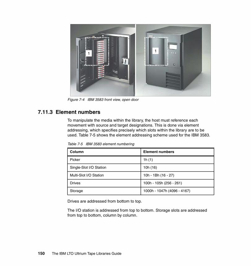
Figure 7-4 IBM 3583 front view, open door
7.11.3 Element numbersTo manipulate the media within the library, the host must reference each movement with source and target designations. This is done via element addressing, which specifies precisely which slots within the library are to be used. Table 7-5 shows the element addressing scheme used for the IBM 3583.
Table 7-5 IBM 3583 element numbering
Drives are addressed from bottom to top.
The I/O station is addressed from top to bottom. Storage slots are addressed from top to bottom, column by column.
11
Column Element numbers
Picker 1h (1)
Single-Slot I/O Station 10h (16)
Multi-Slot I/O Station 10h - 1Bh (16 - 27)
Drives 100h - 105h (256 - 261)
Storage 1000h - 1047h (4096 - 4167)
150 The IBM LTO Ultrium Tape Libraries Guide

7.12 Operator panel and RMUNormally, the host issues commands to the IBM 3583 tape library. Operator control is provided via the Operator Panel or via the TotalStorage Specialist Web interface on the Remote Management Unit (RMU). The operator is responsible for:
� Starting the IBM 3583� Shutting down the IBM 3583� Handling media� Updating firmware� Cleaning drives
For detailed information about operator tasks refer to the Operating Procedures chapter in the IBM 3583 Ultrium Scalable Tape Library Setup and Operator Guide, GA32-0411.
7.12.1 Operator panelThe operator panel provides communication between the operator and the IBM 3583. Visual indications and push buttons enable the operator to control the IBM 3583.
As shown in Figure 7-5 on page 152, the IBM 3583 operator panel is divided into six discrete areas:
� I/O Station status: The I/O Station status area provides constant information about the I/O Station (label 1 in Figure 7-5 on page 152). The information provided will state whether the I/O station is locked. The status of the I/O door and a physical representation of an occupied I/O station slot is indicated by a blacked-out area.
� Library status: The library status area displays informational status such as the library’s online or offline status and the library reports status or messages to solicit operator intervention (label 2 in Figure 7-5 on page 152).
� Messages: The message area displays six lines of text, graphic representations, or a combination of both (label 3 in Figure 7-5 on page 152). Each text line can be up to 20 characters long. The display communicates interactive dialogs, special messages, alerts, and library configurations. More details are covered in Using the Operator Panel Menu in the IBM 3583 Ultrium Scalable Tape Library Setup and Operator Guide, GA32-0411.
Chapter 7. IBM TotalStorage Ultrium Scalable Tape Library 3583 151

� Drive status: The drive status area (label 4 in Figure 7-5) provides constant information about the drives, such as:
– Presence of tape drive (illustrated by a black outlined box for each drive)– Power to the tape drive– Cleaning requirements– Compression– Write protection– Tape activity
� Soft keys: The soft keys reference the push buttons located beneath which are used to perform commands displayed in the soft keys area and to move through the various displays of the operator panel (label 5 in Figure 7-5).
� Push buttons: The actual physical buttons that perform the commands referred to by the soft keys located above each one of them (label 6 in Figure 7-5).
Figure 7-5 IBM 3583 tape library operator panel
152 The IBM LTO Ultrium Tape Libraries Guide

Menu optionsEach menu is accessible through the Operator Panel push buttons. Figure 7-6 shows the flowchart of the IBM 3583 library menu options. For more information about these functions refer to the Operating Procedures chapter in the IBM 3583 Ultrium Scalable Tape Library Setup and Operator Guide, GA32-0411.
Figure 7-6 IBM 3583 flowchart of library functions
Menu guidelinesAll of the the menus and their options are grouped according to function. As shown in Figure 7-7 on page 154, some options are followed by special characters, based on the following system:
� A keyword leading to another menu is suffixed by a small black arrow.� A keyword leading to a dialog box is suffixed with three closely spaced dots.� A keyword leading to an immediate action has no suffix.
Chapter 7. IBM TotalStorage Ultrium Scalable Tape Library 3583 153

Figure 7-7 IBM 3583 soft key symbols
� Most fields on the menus, submenus, dialogs, and screens are read-only. Those fields that are writable are shown in reverse video (Figure 7-8).
Figure 7-8 IBM 3583 operator panel: input field
Using commands that require an offline stateSome commands require that the library be in an offline state. If any such commands are attempted while the library is in an online state, the operator will be requested to take the library offline.
Operator intervention messageIf a problem causes an operator-intervention message to appear, refer to Operator Intervention Messages in the Error Messages appendix of the IBM 3583 Ultrium Scalable Tape Library Setup and Operator Guide, GA32-0411.
7.12.2 RMU with TotalStorage SpecialistThe Remote Management Unit (RMU) provides remote access to the Ultrium Scalable Tape Library over a network. You can attach the library to the network through a 10/100 Ethernet port on the RMU. All available functions are accessible without the need of a dedicated server or separate software. You can access the library through any server on the network by entering the IP address
Note: The information menus are not updated dynamically. To view changes, reselect the menu that was changed.
1 2 3
154 The IBM LTO Ultrium Tape Libraries Guide
or IP name in a Web browser. The operator panel page of the TotalStorage Specialist Web interface is protected by a password and is a direct interface to the operator panel of the attached library.
As shown in Figure 7-9 on page 156, the IBM 3583 TotalStorage Specialist Web interface has three discrete frames:
� Left navigation: The left navigation frame (label 1 in Figure 7-9 on page 156) contains hyperlinks where you can log out the current user, display a brief description of the tabs from the center navigation frame, open the library’s online documentation, download the SNMP MIB file, display contact information for technical support, and display the current version of the RMU firmware.
� Center navigation: The center navigation frame (label 2 in Figure 7-9 on page 156) has tab-style hyperlinks for Status information, Configuration, Firmware, Diagnostics file, Operator panel, and Logs. If you select a tab other than the Status tab, then you have to enter a logon name and password.
� Top information: The top information frame (label 3 in Figure 7-9 on page 156) contains information for you to identify the tape library that you are remotely managing. The frame shows the URL identifier and library type. The URL identifier is the hostname given to the library during initial configuration. The library type is the ID string of the library and is taken from standard inquiry data.
More details are covered in Operator Panel and RMU section in the IBM 3583 Ultrium Scalable Tape Library Setup and Operator Guide, GA32-0411.
Chapter 7. IBM TotalStorage Ultrium Scalable Tape Library 3583 155

Figure 7-9 IBM 3583 TotalStorage Specialist Web interface
7.13 Random accessThe library operates in random access mode, which means that you can access any cartridge in any sequence. This mode normally requires software that generates commands that are sent to the library. The server’s application software manages the cartridges (and thus the data).
7.14 Drive cleaning All of the IBM Ultrium Tape Drives have an integrated cleaning mechanism that brushes the head at load time and again when unloading a cartridge. Along with this, drives have a cleaning procedure using a special cleaning cartridge, should this become necessary.
1 2 3
156 The IBM LTO Ultrium Tape Libraries Guide

With each IBM 3583 tape library, a specially labeled IBM LTO Ultrium Cleaning Cartridge is supplied to clean the drive head. The drive determines when the head needs to be cleaned, and alerts you by displaying CT on the message display.
7.15 Firmware upgradesEach IBM Ultrium tape drive and tape library contains IBM Licensed Internal Code, often referred to as firmware. At installation time, you should make sure the current firmware is installed on your IBM LTO tape drives, library and RMU. As the IBM 3583 is designated as a Customer Setup Machine, it is the customer’s responsibility to have the current firmware installed. Determine the latest level of firmware available from the Web site
http://www-1.ibm.com/support/docview.wss?rs=547&context=STCVQ6Y&q=ssg1*&uid=ssg1S4000044&loc=en_US&cs=utf-8&lang=en+en
Follow the instructions for updating your firmware in the Operating Procedures chapter in the IBM 3583 Ultrium Scalable Tape Library Setup and Operator Guide, GA32-0411, or from
http://ssddom02.storage.ibm.com/techsup/webnav.nsf/support/ltofaqs_updatefw_drivefw
Attention: When cleaning the drive head, use only the IBM LTO Ultrium Cleaning Cartridge or an IBM-approved cleaning cartridge.
Chapter 7. IBM TotalStorage Ultrium Scalable Tape Library 3583 157

158 The IBM LTO Ultrium Tape Libraries Guide
Chapter 8. IBM TotalStorage UltraScalable Tape Library 3584
Designed for automated tape handling, the IBM TotalStorage UltraScalable Tape Library 3584 (IBM 3584) shown in Figure 8-1 on page 160 is the largest member of the IBM Ultrium family of tape library storage solutions. Each aspect of the subsystem is designed to optimize data access and reliability. IBM LTO Ultrium tape drives are compact, high-performance storage devices that support the operations required by today's network and e-business servers. The IBM 3584 supports IBM LTO Ultrium 1 and IBM Ultrium 2 drives.
The IBM TotalStorage UltraScalable Tape Library 3584 provides tape storage solutions for the large, unattended storage requirements from today's mid-range up to enterprise open systems environment. Combining reliable, automated tape handling and storage with reliable, high-performance IBM LTO Ultrium tape drives, the IBM 3584 offers outstanding retrieval performance with typical cartridge move times of less than three seconds.
The IBM 3584 can be partitioned into multiple logical libraries. This makes it an excellent choice for consolidating tape workloads from multiple heterogeneous open-system servers.
8
© Copyright IBM Corp. 2000, 2003. All rights reserved. 159

Figure 8-1 IBM 3584 UltraScalable tape library L32
The IBM 3584 is a modular tape library consisting of frames that house tape drives and cartridge storage slots. You can install a single-frame base library and add up to 15 additional frames, tailoring the library to match your system capacity and performance needs from 14 TB to 1376 TB (28 TB to 2752 TB with 2:1 compression), and using up to 192 IBM LTO Ultrium tape drives. The high granularity of the IBM 3584 library configurations, and its features and capacities are designed to match a wide variety of customer requirements.
The IBM 3584 is an excellent choice if you:
� Are experiencing rapid growth in online storage requirements
� Are considering tape autoloaders and tape libraries with software for automatic backup, archive, or fast-access tape operation to accommodate growth and reduce manual operations
� Have standardized on IBM LTO Ultrium format tape
� Are looking for an IBM LTO Ultrium tape solution requiring large cartridge capacity and fast data streaming transfer capability
160 The IBM LTO Ultrium Tape Libraries Guide
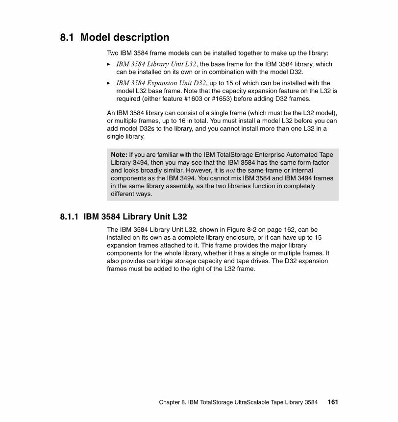
8.1 Model descriptionTwo IBM 3584 frame models can be installed together to make up the library:
� IBM 3584 Library Unit L32, the base frame for the IBM 3584 library, which can be installed on its own or in combination with the model D32.
� IBM 3584 Expansion Unit D32, up to 15 of which can be installed with the model L32 base frame. Note that the capacity expansion feature on the L32 is required (either feature #1603 or #1653) before adding D32 frames.
An IBM 3584 library can consist of a single frame (which must be the L32 model), or multiple frames, up to 16 in total. You must install a model L32 before you can add model D32s to the library, and you cannot install more than one L32 in a single library.
8.1.1 IBM 3584 Library Unit L32The IBM 3584 Library Unit L32, shown in Figure 8-2 on page 162, can be installed on its own as a complete library enclosure, or it can have up to 15 expansion frames attached to it. This frame provides the major library components for the whole library, whether it has a single or multiple frames. It also provides cartridge storage capacity and tape drives. The D32 expansion frames must be added to the right of the L32 frame.
Note: If you are familiar with the IBM TotalStorage Enterprise Automated Tape Library 3494, then you may see that the IBM 3584 has the same form factor and looks broadly similar. However, it is not the same frame or internal components as the IBM 3494. You cannot mix IBM 3584 and IBM 3494 frames in the same library assembly, as the two libraries function in completely different ways.
Chapter 8. IBM TotalStorage UltraScalable Tape Library 3584 161

Figure 8-2 IBM 3584-L32 base frame view from front left
The number of cartridge storage slots ranges from 87 to 281, with the base frame standard of 141 slots, installed in the rear. Additional slots can be added on the door side for a maximum of 281 cartridge slots. The additional slots have to be enabled with the Capacity Expansion feature (FC #1603 or #1653), which enables use of the slots on the door. This gives a maximum data capacity for the L32 of 56 TB native (up to 112 TB with a 2:1 data compression) if you are using LTO 2 Technology. See 8.2.12, “Capacity” on page 181 for precise guidance on model L32 cartridge slot storage capacities.
At least one tape drive must be installed in the model L32 with the option to install 11 more drives for a maximum of 12 tape drives in the L32 frame. As you add drives, there is an incremental reduction in storage slots once you exceed four installed drives.
Each L32 has a standard 10-slot cartridge input/output station for importing or exporting cartridges from the library without requiring re-inventory or interruption of library operations. Optional features can provide 20 additional input/output slots. The lockable library door can be opened for bulk-loading IBM LTO Ultrium tape cartridges. Re-inventory of the cartridges is done in less than 60 seconds per frame each time the library door is closed. A barcode reader mounted on the autochanger scans the cartridge labels at less than one minute per frame. A door lock is included to restrict physical access to cartridges in the library.
I/O Station(10 Cartridges)
LockableFro nt Door
O perator P anelw ith Touch-S creen
Liquid Crys tal D isplay
F irs t B ox In String p rov id es :Ro botDrivesCa rtridg e Stora geI/O s ta tio n (10 cartridg es)O pe ra tor C ontro lsHo st Atta chm ent
A uto-C alibra tin gS CSI Me dium Ch ang er In te rface
V iew ing W indows
162 The IBM LTO Ultrium Tape Libraries Guide

8.1.2 IBM 3584 Expansion Unit D32The IBM 3584 Expansion Unit D32, shown in Figure 8-3, cannot be installed without the L32 base frame, which must be the first frame in the library. The L32 frame also must have the capacity expansion feature (FC #1603 or #1653) installed as a prerequisite to install additional D32 frames. The D32 provides cartridge storage space and houses additional drives. Up to 15 expansion frames can be added to the L32 base frame.
When no drives are installed, the D32 has 440 installed cartridge storage slots. An L32 base frame and 15 D32 expansion frames with a minimal drive configuration provides a maximum capacity of 6881 storage slots with a total capacity of 1376 TB without compression using IBM Ultrium 2.
Figure 8-3 IBM 3584-D32 library expansion frame viewed from the right
Each IBM D32 houses up to 12 drives; the minimum number of installed drives is zero. In other words, you do not have to install tape drives in the model D32, but can use it solely to expand the number of storage slots in the library.
If one or more tape drives are installed in the D32 then the Frame Control Assembly Feature is also required (#1452). This feature provides the hardware and firmware required to support IBM LTO Ultrium drives within the D32, and also provides a redundant AC line feed for the L32 accessor.
Chapter 8. IBM TotalStorage UltraScalable Tape Library 3584 163

The base L32 is always on the left and as many as 15 additional D32 expansion frames can be added to the right side. During the installation of additional D32 frames, the x-rail of the L32 frame where the accessor resides will be extended, so that the accessor can move through the new installed frame.
A fully configured IBM 3584 with one L32 frame and 15 D32 frames (see Figure 8-4) supports up to 192 drives. As you add drives to each D32, there is an incremental reduction of storage slots for each set of four tape drives you install.
Figure 8-4 IBM 3584 with 16 frames
16 frames192 LTO drives
6881 slots
164 The IBM LTO Ultrium Tape Libraries Guide

8.2 Library componentsThe major IBM 3584 library components are shown in Figure 8-5.
Figure 8-5 IBM 3584 library showing the major library components
8.2.1 Tape drivesThe IBM 3584 library houses IBM LTO Ultrium drives. Both Ultrium 1 and Ultrium 2 drives may be installed in the same frame.
1. Library frame 2. x-Rail system3. Cartridge accessor4. Dual-gripper transport mechanism5. Accessor controller6. Cartridge storage slots
7. IBM LTO Ultrium drive8. Front door9. Door safety switch10. I/O station11. Operator panel and controller
Chapter 8. IBM TotalStorage UltraScalable Tape Library 3584 165

IBM LTO Ultrium drives may be attached to a SCSI host system using HVD, LVD, or FC connectors. The particular drive interface is specified by the ordering feature code on the IBM 3584 model type:
� Feature #1454, LTO Ultrium 1 LVD Drive Canister� Feature #1455, LTO Ultrium 1 HVD Drive Canister� Feature #1456, LTO Ultrium 1 FC-AL Drive Canister� Feature #1474, LTO Ultrium 2 LVD Drive Canister� Feature #1475, LTO Ultrium 2 HVD Drive Canister� Feature #1476, LTO Ultrium 2 Fibre Drive Canister
At least one of these drive features must be ordered on the initial L32 for a new library, and a maximum of 12 of these features may be added to each library frame model type. The features may be intermixed.
Although the IBM LTO Ultrium drive modules are the same for all IBM LTO libraries, the tape drive assembly used in the IBM 3584 libraries (Figure 8-6) is packaged uniquely. Therefore, the drives cannot be interchanged between library models. The tape drive assembly contains the drive power supply and the LTO drive (HVD, LVD or FC) itself. Each drive power supply is strong enough to support two tape drives.
Figure 8-6 IBM 3584 LTO Ultrium tape drive assembly
For redundancy reasons, two drive power supplies deliver power for each two drives, as shown in Figure 8-7 on page 167. If one drive power supply fails, then the second power supply provides power for both drives, and both drives continue running.
LTO drive
Drive power supply
166 The IBM LTO Ultrium Tape Libraries Guide

Figure 8-7 Redundant drive power supply
8.2.2 Library control systems: frame control assemblyA library control system is required for a library to operate. Conventional libraries, such as the IBM 3494, use a single library controller that handles all of the different inputs and controller output commands. The IBM 3584 uses a system of distributed embedded controllers. There are controllers, each with its own processor, for the operator panel, the accessor controller that handles the accessor and gripper, XY controller for the X and Y movements and medium changer controller for handling the commands coming from the host (Figure 8-8).
Figure 8-8 IBM 3584 distributed control system
Drive
Drive
Drive
Drive
+5V , +12VDC
+5V , +12VDC
+5V , +12VDC
+5V , +12VDC
Accessor controller
XY controller
Medium changer
controller
Operator panel
controller
Distributed Control System
Chapter 8. IBM TotalStorage UltraScalable Tape Library 3584 167

The four controllers are in different locations. The operator panel controller is located directly on the Operator Panel. The accessor and XY controllers are attached to the accessor. The medium changer controller, which is hosted within the frame controller assembly, is mounted in the rear of the frame (Figure 8-9).
Figure 8-9 IBM 3584 distributed control system
For redundancy, the medium changer controller, which is part of the frame controller assembly (FCA), is required in each D32 frame where at least one tape drive is installed (Figure 8-10 on page 169). It is optional in a D32 with no tape drives.
XY controller
Medium changer controller
Accessor controller
Operator panel controller
168 The IBM LTO Ultrium Tape Libraries Guide

Figure 8-10 Redundant medium changer controller
The frame controller assembly (FCA) (see Figure 8-11 on page 170) is a canister containing:
� Medium changer controller � AC outlets for tape drive power supplies� DC power supplies for the whole library controlller� Circuit breakers� Incoming main AC power
The FCA for the L-Frame contains two DC power supplies; actually, only one DC power supply is needed to operate the whole IBM 3584 library. Before support was provided for 16 frames, all additional FCAs in D-Frames included one extra DC power supply for redundancy. With support for 16 frames, the additional FCAs in the D-Frames no longer have a default-installed DC power supply.
With support for 16 frames, however, you can order additional DC power supplies (FC #1902) for the D32 frames. This makes sense if not using the Dual AC power options (FC #1901); see 8.5.4, “Power and cooling specifications” on page 191. If you wish, an IBM Customer Engineer can put one of the two DC power supplies from the L-Frame into another FCA in a D-Frame to provide redundancy for both AC and DC power.
Accessor Controller
Medium Changer
Controller
Operator Panel
Controller
Frame 1 Frame 2 Frame 3
Medium Changer
Controller
Medium Changer
Controller
XY Controller
Additional expansion components are simply
plugged into existing power and communications
Chapter 8. IBM TotalStorage UltraScalable Tape Library 3584 169
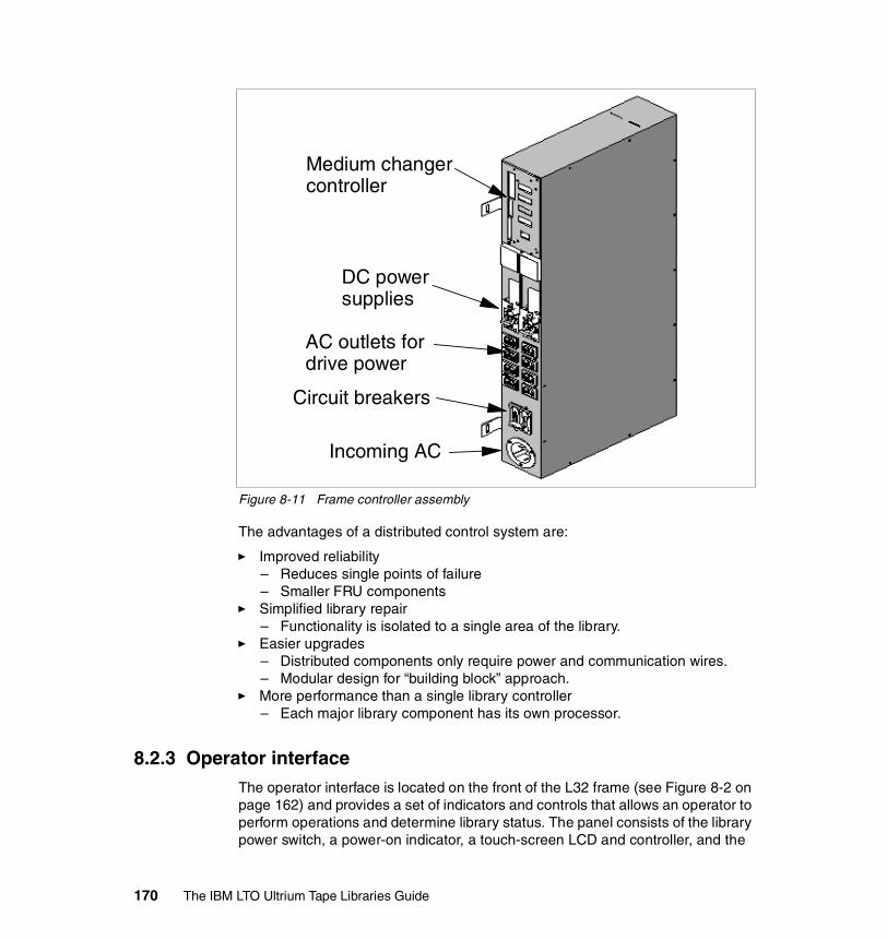
Figure 8-11 Frame controller assembly
The advantages of a distributed control system are:
� Improved reliability– Reduces single points of failure– Smaller FRU components
� Simplified library repair– Functionality is isolated to a single area of the library.
� Easier upgrades– Distributed components only require power and communication wires.– Modular design for “building block” approach.
� More performance than a single library controller– Each major library component has its own processor.
8.2.3 Operator interfaceThe operator interface is located on the front of the L32 frame (see Figure 8-2 on page 162) and provides a set of indicators and controls that allows an operator to perform operations and determine library status. The panel consists of the library power switch, a power-on indicator, a touch-screen LCD and controller, and the
Medium changer controller
DC power supplies
Incoming AC
AC outlets for drive power
Circuit breakers
170 The IBM LTO Ultrium Tape Libraries Guide

controller for the I/O station. The operator panel controller is located inside the library behind the operator panel (number 11 in Figure 8-5 on page 165). It is a logic card that facilitates communication between the operator panel and the accessor controller. The operator panel controller posts status and information about the sensing and locking of the I/O station to the operator panel LCD.
The operator panel touch screen (Figure 8-12) consists of the touch keys area and the activity and status screen. The activity screen displays LmultCD on the touch screen when the library is ready (that is, when host applications may interact with the library). The first line on the screen shows the current level of library firmware and the panel screen number. The left field on the second line indicates that the library is either ready, not ready (not interacting with host applications), or initializing. The right field indicates the status of one or more I/O stations. The activity screen also shows the current activity in a large font, and provides a history of preceding operations in a smaller font. Operations are listed from top to bottom with the most recent at the top. The activity screen automatically displays an error message when an error condition is detected. See 8.9, “Operator displays and buttons” on page 196 for more information.
Figure 8-12 Operator panel
Touch buttons
Current activity
History
Status & I/O port
Chapter 8. IBM TotalStorage UltraScalable Tape Library 3584 171

8.2.4 Robotic cartridge accessorThe cartridge accessor is the assembly that moves tape cartridges between storage slots, tape drives, and the I/O station (number 3 in Figure 8-5 on page 165). The accessor assembly moves horizontally through the library frames using a rail system (number 2 in Figure 8-5 on page 165); it uses both top and bottom rails.
The accessor assembly consists of a dual gripper (number 4 in Figure 8-5 on page 165 and in more detail in Figure 8-13) mounted on a vertical pole. The gripper can move up and down vertically, and also rotates to access cartridge slots on both the back walls and front doors of the library frames. A barcode reader is mounted on the accessor and can scan the cartridges in one frame in less than a minute.
Figure 8-13 IBM 3584 accessor assembly
X- and Y-axis motion assembliesThese assemblies include a controller (circuit board) for the Controller Area Network interface, servo motor, pinion drive gear, and lead screw. These assemblies provide the motive force to move the accessor side to side (on the
172 The IBM LTO Ultrium Tape Libraries Guide
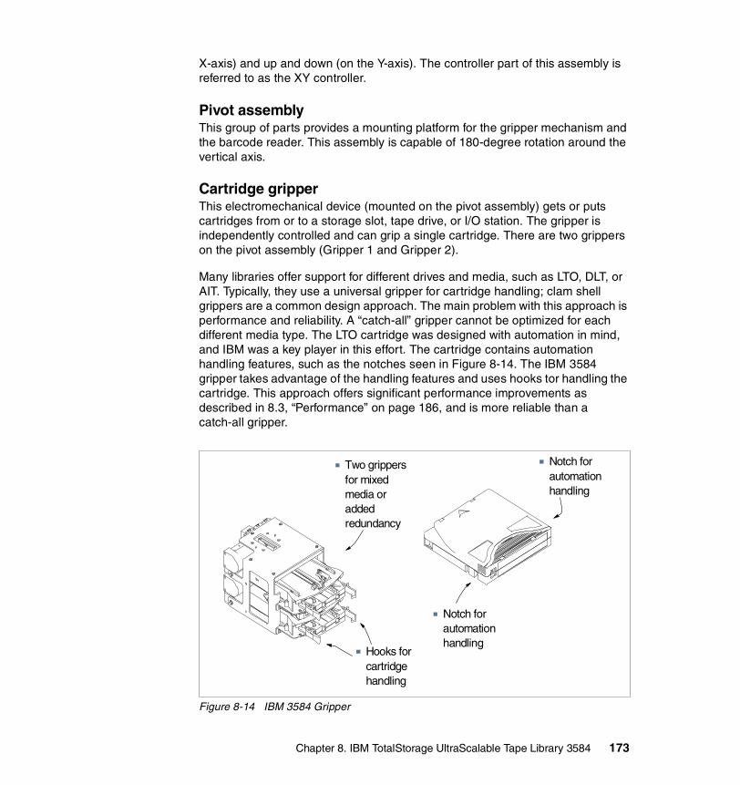
X-axis) and up and down (on the Y-axis). The controller part of this assembly is referred to as the XY controller.
Pivot assemblyThis group of parts provides a mounting platform for the gripper mechanism and the barcode reader. This assembly is capable of 180-degree rotation around the vertical axis.
Cartridge gripperThis electromechanical device (mounted on the pivot assembly) gets or puts cartridges from or to a storage slot, tape drive, or I/O station. The gripper is independently controlled and can grip a single cartridge. There are two grippers on the pivot assembly (Gripper 1 and Gripper 2).
Many libraries offer support for different drives and media, such as LTO, DLT, or AIT. Typically, they use a universal gripper for cartridge handling; clam shell grippers are a common design approach. The main problem with this approach is performance and reliability. A “catch-all” gripper cannot be optimized for each different media type. The LTO cartridge was designed with automation in mind, and IBM was a key player in this effort. The cartridge contains automation handling features, such as the notches seen in Figure 8-14. The IBM 3584 gripper takes advantage of the handling features and uses hooks tor handling the cartridge. This approach offers significant performance improvements as described in 8.3, “Performance” on page 186, and is more reliable than a catch-all gripper.
Figure 8-14 IBM 3584 Gripper
Notch for automation handling
Hooks for cartridge handling
Two grippers for mixed media or added redundancy
Notch for automation handling
Chapter 8. IBM TotalStorage UltraScalable Tape Library 3584 173

The use of a dual-gripper accessor reduces the time taken to move cartridges in the library and can improve overall performance on large libraries. It increases redundancy and reliability. Note that library functions are controlled by host application software, and to make use of the dual gripper function, the software itself must be able to use two grippers simultaneously. If it does not, then the library will function as if it had only a single gripper. If only one gripper is used at a time, the library periodically switches between both grippers to balance use.
Barcode readerThe barcode reader reads the barcode on a label that is attached to a cartridge or at the rear of every storage slot (which indicates an empty storage slot). The barcode reader is mounted on the pivot assembly, and is used during inventories, audits, insertions, and inventory updates. The inventory is updated whenever the door is opened, and determines whether cartridges have been added to, removed from, or moved within the library).
Because all storage slots have empty storage cell labels, the library can easily and quickly recognize if there is a labelled cartridge or an empty storage slot in every location. This eliminates the need to reread or manually intervene in storage cells if no label is readable. Without this approach the library cannot differentiate between a slot that is unlabeled, badly labelled, or empty.
Calibration sensorThis provides a means to locate certain positions within the library very precisely during the calibration operation. The calibration sensor is mounted on the underside of Gripper 1. All positions are calculated from these locating positions.
8.2.5 Rail assemblyThe cartridge accessor moves through the library on a rail assembly (number 2 in Figure 8-5 on page 165). The system consists primarily of a main rail assembly and support rail, and a trough for the power and control cable. The main rail assembly includes a main bearing way with a rack gear. Its support rail is an L-shaped rail that runs along the top of the frames and provides smooth transport for the cartridge accessor. The power and control cable is kept clear of the accessor in a covered trough at the bottom rear of the library.
8.2.6 Library centric WWN conventionEvery device in a SAN environment uses a unique WWN for identification in the SAN. In a conventional library, if the drives are swapped then the WWN will also be changed and hence you have to reconfigure both the SAN and the server. If you are using persistent binding on your server, a server reboot is also necessary.
174 The IBM LTO Ultrium Tape Libraries Guide

The IBM 3584 assigns the WWNs to the drives. This technique is referred to as “library centric world wide names.” Every potential drive slot is assigned with a unique WWN. If a drive is replaced, then the new drives gets the same WWN as the old one. This is controlled by the FCA. Because of this library behavior, you can easily identify the position of the drive in the library by the WWN. The last two digits represent the drive’s location in the library. The last digit indicates the drive row, starting from 1, and the second last indicates the frame, counting from 0. The remaining digits are encoded with the vendor ID and the library serial number, ensuring that every drive has a unique WWN. Figure 8-15 shows the drive WWNs in an IBM 3584.
Figure 8-15 Drive WWNs of an IBM 3584
8.2.7 Control path failoverAlternate path support, currently available only for AIX hosts, configures multiple physical control paths to the same logical library within the device driver and provides automatic failover to an alternate control path when a permanent error occurs on one path. This is transparent to the running application.
For example, consider a simple multi-path architecture connection consisting of two HBAs in an AIX host that are connected to a library with two or more drives (Figure 8-16 on page 176). Two drives have the control ports enabled. The two HBAs are connected to the first and second control port drives, respectively. This simple configuration provides two physical control paths to the library for
Chapter 8. IBM TotalStorage UltraScalable Tape Library 3584 175
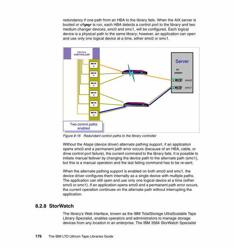
redundancy if one path from an HBA to the library fails. When the AIX server is booted or cfgmgr is run, each HBA detects a control port to the library and two medium changer devices, smc0 and smc1, will be configured. Each logical device is a physical path to the same library; however, an application can open and use only one logical device at a time, either smc0 or smc1.
Figure 8-16 Redundant control paths to the library controller
Without the Atape (device driver) alternate pathing support, if an application opens smc0 and a permanent path error occurs (because of an HBA, cable, or drive control port failure), the current command to the library fails. It is possible to initiate manual failover by changing the device path to the alternate path (smc1), but this is a manual operation and the last failing command has to be re-sent.
When the alternate pathing support is enabled on both smc0 and smc1, the device driver configures them internally as a single device with multiple paths. The application can still open and use only one logical device at a time (either smc0 or smc1). If an application opens smc0 and a permanent path error occurs, the current operation continues on the alternate path without interrupting the application.
8.2.8 StorWatchThe library’s Web interface, known as the IBM TotalStorage UltraScalable Tape Library Specialist, enables operators and administrators to manage storage devices from any location in an enterprise. The IBM 3584 StorWatch Specialist
DRIVE
1
DRIVE
2
Lib ra ry CONTROLLER
DRIVE
3
DRIVE
4
DRIVE
5
DRIVE
6
Two control paths enabled
FC adapter
Server
smc0
smc1
176 The IBM LTO Ultrium Tape Libraries Guide

allows direct communication with an IBM 3584 and provides a full range of end user, operator, and administrator tasks, which can be executed remotely.
The StorWatch Specialist requires a Category 5 Ethernet cable (not supplied with the tape library).
Multiple simultaneous Web clientsEach Ethernet capable medium changer controller (MCC) on the IBM 3584 allows five simultaneous StorWatch users.
Individual Web login IDs and passwordsFor the IBM 3584, the Web user interface supports a list of users that can access various areas of the Web user interface. Each user has a 30-character name, a 15-character login ID, a 15-character password, and an access level. The access level defines the level of Web access that the user is allowed. The two levels of access are “user” for non-destructive Web access and “super user” for more advanced functionality such as moving cartridges and configuring the library. User and super user login IDs cannot create, modify, or change any login IDs. Any login ID can change their own password. The special login ID “admin” can create, modify, and destroy all login IDs except the admin ID.
Multiple simultaneous Web clients and individual Web ID functions can be made available to existing IBM 3584 libraries by upgrading to the latest firmware.
8.2.9 I/O stationEach L32 frame has a standard 10-slot cartridge input/output station for importing or exporting cartridges from the library without requiring a re-inventory or interruption of library operations. An optional feature (FC # 1657) provides 20 additional input/output slots.
8.2.10 ReliabilityThe IBM 3584 is designed for high availability and reliability. Most essential components are redundant, so there is no single point of failure. Most of these components have been described previously. Here is a summary of the high-availability features and components of the IBM 3584:
� Redundant grippers
– A failure of one gripper will cause the library to switch to a second gripper.
� Redundant library power
– Each drive frame provides one additional power supply.
Chapter 8. IBM TotalStorage UltraScalable Tape Library 3584 177

– A single frame library contains one redundant power supply.
• Optional redundant frame power available
– The library can operate on a single power supply.
– The library automatically monitors and controls redundant power distribution.
� Redundant drive power
– Each drive bay power module supplies redundant power to another drive bay.
� Redundant control paths
– Any LTO drive can be used as a library control path.
– Automatic control path failover available for AIX.
� Redundant copies of Vital Library Data
– Includes configuration data, calibration data, setup data, etc.
– One processor card contains the primary copy and another processor card contains a backup copy.
– Backup/restore process is completely automated
� Redundant copies of library firmware
– Each processor card contains the firmware for every other processor card.
– Component replacement is simplified.
– Each processor card contains two copies of operational firmware.
– Protects the library from potentially harmful firmware update disruptions.
– Helps reduce the risk of memory failures.
� Closed loop servo systems
– Includes horizontal motion, vertical motion, pivot motion, gripper extend, and retract motion.
– Each servo system uses feedback.
– Velocity and position are monitored.
– Allows higher performance (as shown in Table 8-5 on page 187).
• Knowing velocity and position allows greater control.
– Closed loop is more reliable.
– Collisions and gripper damage can be avoided by monitoring position and velocity.
178 The IBM LTO Ultrium Tape Libraries Guide

8.2.11 ServiceThis section describes support and service for the IBM 3584.
Call-homeThe library calls an IBM Support Center when an error occurs. The library reports codes indicating the replacement parts that may be required and the urgency of the problem. No-charge feature #2710 (Remote Support Facility) provides a modem and cable (15.2 m or 50 feet). The customer must provide an analog phone line to use the call-home feature. This phone line should be close to the library (within 15.2 m; 50 feet).
If a second 3584 (L32) library is installed close (within 15.2 m or 50 feet) to the first one, you can order feature #2711 (Remote Support Switch) for the second library. This feature provides a modem switch in order to share the modem from the first library. The benefit is that a single phone line can service both libraries.
For the third and every subsequent 3584, installed close to the first one (within 15.2 m or 50 feet), you can order feature #2712 (Remote Support Attachment). This provides cabling for connecting to the Remote Support Switch. A maximum of 14 libraries can be connected to the switch.
If the additional libraries are not close together, then feature #2710 and a phone line is required for each one.
FirmwareAs described in 8.2.2, “Library control systems: frame control assembly” on page 167, the IBM 3584 has four control assemblies. Each of them has the complete firmware image stored on flash ROMs. The same firmware image is stored on each card, avoiding the need to keep multiple code images in sync. A node card may only use a small portion of the firmware image, but it has the whole image in its flash. The node card firmware provides the ability to communicate with other node cards. The node cards can determine the level of firmware on other node cards and can request a copy of the firmware from another node card. This ability enables the cards to operate automatically at a consistent firmware level throughout the library subsystem.
When a node card completes its Power-On Self Test (POST), it asks all of the other node cards to report their firmware levels. If it determines that another node card has a higher version of firmware, it will obtain the firmware from that node card and update its flash ROM before coming online. This ensures that when a node card FRU containing down-level firmware is installed in the library, it will be updated automatically.
Chapter 8. IBM TotalStorage UltraScalable Tape Library 3584 179

Each node card contains two complete copies of the firmware in flash ROM for redundancy. If a problem such as a power failure interrupts a firmware update, the node card can automatically switch to the backup copy. Another attempt can then be made to update the firmware. The update process always overwrites the damaged or oldest firmware image first, so the node cards should always have a usable level of firmware.
During replacement of tape drives, the library automatically detects the firmware version of the newly installed drive and, if needed, updates the drive firmware.
This behavior of the IBM 3584 avoids any potential for replacement parts containing a wrong firmware version.
SNMPOccasionally, the IBM 3584 may encounter a situation that should be reported, such as an open door that causes the library to stop. Because many servers can attach to the IBM 3584 by differing attachment methods, the library provides a standard TCP/IP protocol called Simple Network Management Protocol (SNMP) to send alerts about conditions (such as an opened door) over a TCP/IP LAN network to an SNMP monitoring server. These alerts are called SNMP traps. Using the information supplied in each SNMP trap, the monitoring server (together with customer-supplied software) can alert operations staff of possible problems or operator interventions that occur. Many monitoring servers (such as Tivoli NetView®) can be used to send e-mail or pager notifications when they receive an SNMP alert.
The monitoring server must be loaded with systems management software that can receive and process the trap, or the trap will be discarded. SNMP trap support does not provide a mechanism for the operator to gather more information about a problem or to query the library about its current status.
If your systems management software includes an SNMP compiler, you may not need to manually interpret SNMP traps but you will need the library’s Management Information Base (MIB). The MIB contains units of information that specifically describe an aspect of a system, such as the system name, hardware number, or communications configuration. Obtain the MIB for the IBM 3584 from:
ftp://ftp.software.ibm.com/storage/358x/3584
ConfigurationThe IBM 3584 automatically configures and calibrates itself as initiated from the operator panel or StorWatch. New hardware is automatically discovered. This eliminates the user or IBM engineer from entering invalid data.
180 The IBM LTO Ultrium Tape Libraries Guide

8.2.12 CapacityThe overall size of an IBM 3584 library frame (either L32 or D32), allows for up to 10 storage columns: five columns located on the back wall of the frame and five on the interior of the door (see Figure 8-17 on page 182 and Figure 8-18 on page 184). Each column is made up of 44 slots, so the maximum available cartridge storage capacity of the D32 frame is 440 (44 times 10).
In practice, some installed library components take up space inside the library frames, which reduces the space available for cartridge slots. Some of these library components are installed as standard (for example, in the model L32 where the maximum capacity is 281), and some are variable, for example the installation of drives in either frame model type).
This section explains the layout of the cartridge slots in the interior of each of the model types and provides tables to calculate the library capacity for various configurations.
Model L32 In the Model L32, the robotic home position utilizes the area to the left of the frame and prevents access to any cartridge slots in that area. This means that there are eight cartridge slot columns in the model L32, four on the back wall of the frame and four on the inside of the door. In addition, the I/O station takes up space on the inside of the door, and the drive positions take up space on the back wall, further reducing the cartridge slots available.
The layout of the cartridge slots and columns is shown in Figure 8-17 on page 182. The columns are numbered with those on the back wall designated as numbers 1, 3, 5, and 7, while those inside the door are numbers 2, 4, 6, and 8. Therefore column number 1 faces column number 2, 3 faces 4, and so on.
In order to provide a less expensive entry level tape solution, only columns 1, 3, 5, and 7 (those on the back wall) are accessible in the standard L32 frame. If greater capacity is needed, order a chargeable feature (the capacity expansion feature, feature codes #1603 or #1653) to make columns 2, 4, 6, and 8 available to store cartridges (noting that some of the slot positions in columns 2 and 4 are occupied by the cartridge I/O station, as shown in Figure 8-17 on page 182). The capacity expansion feature must be added before expanding the library with any D32 expansion frames.
Chapter 8. IBM TotalStorage UltraScalable Tape Library 3584 181

Figure 8-17 IBM 3584-L32 base frame showing cartridge slot components
The tape drives inside the L32 frame take up space in columns 5 and 7 on the right side of the back wall of the library as shown in Figure 8-17. As the drives are added, there is an incremental reduction in cartridge storage space. At least one drive must be installed in the L32 frame, and since drive positions are reserved in sets of four, this removes one-third of the cartridge slots from columns 5 and 7. When you install the fifth drive, this removes another third of the slots from columns 5 and 7, until finally, when the ninth drive is installed, the drive positions take up all of the space where columns 5 and 7 would have been located.
The very first slot in the L32 frame (column1 row 1) at the top left side of the back wall is always reserved for a diagnostic cartridge.
Not accessible withoutexpansion feature
182 The IBM LTO Ultrium Tape Libraries Guide
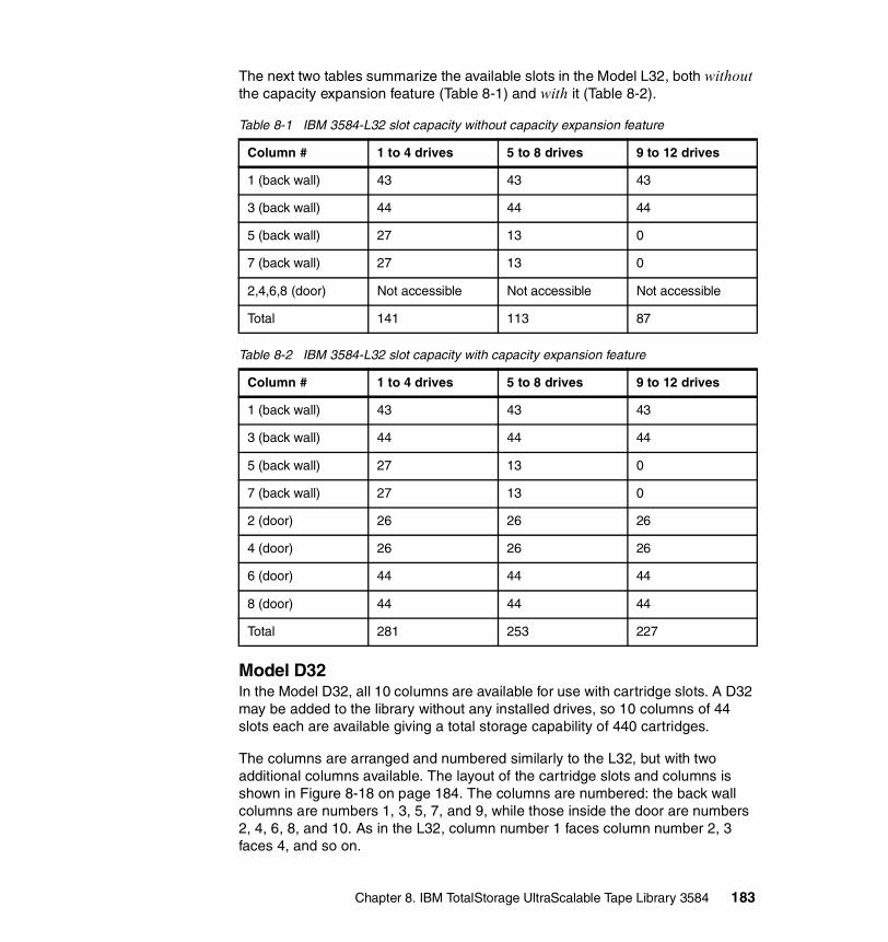
The next two tables summarize the available slots in the Model L32, both without the capacity expansion feature (Table 8-1) and with it (Table 8-2).
Table 8-1 IBM 3584-L32 slot capacity without capacity expansion feature
Table 8-2 IBM 3584-L32 slot capacity with capacity expansion feature
Model D32 In the Model D32, all 10 columns are available for use with cartridge slots. A D32 may be added to the library without any installed drives, so 10 columns of 44 slots each are available giving a total storage capability of 440 cartridges.
The columns are arranged and numbered similarly to the L32, but with two additional columns available. The layout of the cartridge slots and columns is shown in Figure 8-18 on page 184. The columns are numbered: the back wall columns are numbers 1, 3, 5, 7, and 9, while those inside the door are numbers 2, 4, 6, 8, and 10. As in the L32, column number 1 faces column number 2, 3 faces 4, and so on.
Column # 1 to 4 drives 5 to 8 drives 9 to 12 drives
1 (back wall) 43 43 43
3 (back wall) 44 44 44
5 (back wall) 27 13 0
7 (back wall) 27 13 0
2,4,6,8 (door) Not accessible Not accessible Not accessible
Total 141 113 87
Column # 1 to 4 drives 5 to 8 drives 9 to 12 drives
1 (back wall) 43 43 43
3 (back wall) 44 44 44
5 (back wall) 27 13 0
7 (back wall) 27 13 0
2 (door) 26 26 26
4 (door) 26 26 26
6 (door) 44 44 44
8 (door) 44 44 44
Total 281 253 227
Chapter 8. IBM TotalStorage UltraScalable Tape Library 3584 183

All 10 columns are accessible as soon as the D32 is installed; there is no need for any capacity-expansion feature for this frame. However, note that the L32 must be fully configured for capacity before adding any model D32 frames to it. In other words, the L32 must have the capacity expansion feature installed.
The robotic home position is in the L32 and there is only one I/O station per library, which is also located in the door of the L32, so the installation of tape drives is the only factor reducing the available cartridge storage slots in the D32.
The capacity expansion feature may be ordered either for installation at the manufacturing plant as feature #1653 or as a field upgrade, feature #1603.
Figure 8-18 IBM 3584-D32 expansion frame showing slot components
184 The IBM LTO Ultrium Tape Libraries Guide
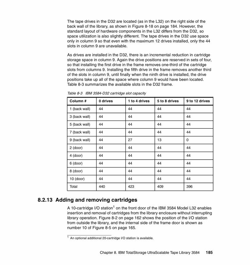
The tape drives in the D32 are located (as in the L32) on the right side of the back wall of the library, as shown in Figure 8-18 on page 184. However, the standard layout of hardware components in the L32 differs from the D32, so space utilization is also slightly different. The tape drives in the D32 use space only in column 9 so that even with the maximum 12 drives installed, only the 44 slots in column 9 are unavailable.
As drives are installed in the D32, there is an incremental reduction in cartridge storage space in column 9. Again the drive positions are reserved in sets of four, so that installing the first drive in the frame removes one-third of the cartridge slots from columns 9. Installing the fifth drive in the frame removes another third of the slots in column 9, until finally when the ninth drive is installed, the drive positions take up all of the space where column 9 would have been located. Table 8-3 summarizes the available slots in the D32 frame.
Table 8-3 IBM 3584-D32 cartridge slot capacity
8.2.13 Adding and removing cartridgesA 10-cartridge I/O station1 on the front door of the IBM 3584 Model L32 enables insertion and removal of cartridges from the library enclosure without interrupting library operation. Figure 8-2 on page 162 shows the position of the I/O station from outside the library, and the internal side of the frame door is shown as number 10 of Figure 8-5 on page 165.
Column # 0 drives 1 to 4 drives 5 to 8 drives 9 to 12 drives
1 (back wall) 44 44 44 44
3 (back wall) 44 44 44 44
5 (back wall) 44 44 44 44
7 (back wall) 44 44 44 44
9 (back wall) 44 27 13 0
2 (door) 44 44 44 44
4 (door) 44 44 44 44
6 (door) 44 44 44 44
8 (door) 44 44 44 44
10 (door) 44 44 44 44
Total 440 423 409 396
1 An optional additional 20-cartridge I/O station is available.
Chapter 8. IBM TotalStorage UltraScalable Tape Library 3584 185

The I/O station is controlled by the host application software that uses the library or from the operator panel. Insertion of cartridges into the I/O station alerts the application software, which registers the additional cartridges and their status in its database and then instructs the accessor to move the new cartridges into library slots. The slot location of each cartridge is held in the host application software database.
For bulk-loading of cartridges (more than 10), you can open any library frame door and insert cartridges in any available slots in the frame. When the door is closed, the library will perform a cartridge inventory operation, which checks to determine whether each cartridge storage slot in the frame is empty or full and scans the cartridge barcode labels. When the library performs an automatic inventory in this way, the inventory will occur only for those frames whose doors had been opened.
A cartridge inventory operation occurs whenever you:
� Power on the library� Issue the SCSI command Initialize Element Status with Range2
� Select Inventory from the Manual Operations menu� Select the appropriate menus from the UltraScalable Specialist Web interface� Close the front door after manually accessing the library
When the library performs an automatic inventory because the front door was closed, the inventory occurs only for those frames whose doors have been opened. A door lock is provided to restrict physical access to cartridges in the library. This can be used to secure the cartridges and prevent unauthorized library access. Although the time required for the library to inventory cartridges is less than 60 seconds per frame, the door lock reduces the possibility of frames being opened in error and causing unnecessary inventory activity.
There is also a safety switch in the frame door (number 9 in Figure 8-5 on page 165) that shuts down the power to the cartridge accessor whenever the front door is opened.
8.3 PerformanceThe performance capability of a tape library solution depends on both the individual bandwidth capability of the drives and data bus and the speed of the robotic handling. The degree of importance for each of these elements depends on the quantity of data transferred during one operation. For example, when reading or writing large files (larger than 800 MB) to tape, then the data rate of
2 The 3584 library tracks the logical location of all elements in the library by performing an automatic inventory as required (thus, the SCSI Initialize Element Status command is allowed but ignored).
186 The IBM LTO Ultrium Tape Libraries Guide

the tape drive will be the overriding contributor to the speed of the operation. However, for reading or writing many small files (25 MB or less) to different tapes then the cartridge move and load times become the overriding contributor.
The following elements contribute to the high-performance capabilities of IBM 3584 libraries:
� Library bandwidthYou see the bandwidth of the IBM 3584 in Table 8-4 relating to the drive performance given in 2.4.4, “Performance” on page 35. Values in the compressed column assume a compression of 2:1.
Table 8-4 IBM 3584 bandwidth
� Cartridge move timeIn a single-frame IBM 3584, the typical time to move a cartridge from a cartridge storage slot to a tape drive, for example, is less than 2.5 seconds, For a six-frame configuration it only increases to 4.5 seconds, and for the maximum 16 frames, the average move time is still only 9 seconds, as shown in Table 8-5.
Table 8-5 Library performance
Here are some thoughts about the relationship between drives per library and mounts per hour:
– If you do mainly full backups that fill entire cartridges at a time, an Ultrium 1 drive needs about 111 minutes and an Ultrium 2 about 95 minutes to fill a cartridge. This means that you have to mount an Ultrium 1
Tape drives LTO Ultrium 1native
LTO Ultrium 1compressed
LTO Ultrium 2native
LTO Ultrium 2compressed
72 3.8 TB/h 7.7 TB/h 9.0 TB/h 18.1 TB/h
192 10.3 TB/h 20.7 TB/h 24.1 TB/h 47.4 TB/h
Library configuration Average move times Mounts per hour
1 Frame 2.4 seconds 600
2 Frames 2.5 seconds 515
4 Frames 3.0 seconds 405
6 Frames 3.8 seconds 340
8 Frames 4.9 seconds 265
12 Frames 6.5 seconds 205
16 Frames 8.0 seconds 165
Chapter 8. IBM TotalStorage UltraScalable Tape Library 3584 187
drive 0.54 times per hour and an Ultrium 2 drive 0.63 times per hour. Even in a 16-frame library with 192 drives, you should not encounter any performance problems stemming from the mount capability of the library.
– If you mount a cartridge, read or write a small piece of data, unmount the cartridge, and repeat, then a drive is busy for approximately three minutes to execute this cycle (load, search, read/write, rewind, unload). This means you might mount a cartridge not more than 20 times per hour. In this worst-case scenario, you may see mount performance affecting library performance.
Both of these theoretical cases should help you determine how many tape drives you should install in the library to avoid mount performance problems.
� Library inventory timeDuring normal use of the IBM 3584, for bulk loading of cartridges the library will perform an inventory operation to check the (possibly new) content of the cartridge storage slots. During this time, the accessor is occupied scanning the bar code labels and empty slots.
The inventory process for the IBM 3584 is performed very efficiently, usually taking less than 60 seconds per frame.
8.4 Upgrades and optional featuresThe IBM 3584 has a number of optional additional features. These enhance the library by providing extra functions, additional capacity, higher reliability, and greater serviceability.
8.4.1 Upgrade featuresYou can install an entry-level system with moderate capacity then upgrade it as capacity requirements increase by ordering extra features. A single-frame, single-drive system can be expanded over time to become a fully configured 16-frame 192-drive library.
Adding cartridge capacityYou can add capacity to an installed library in several ways:
� The #1603 capacity expansion feature can be applied to a standard model L32 (one without #1603 or #1653 already installed). This feature enables the use of 140 cartridge storage cells on the inside of the door.
� Model D32 expansion frame can be added to the base L32 frame to provide a maximum of 440 extra storage slots. To provide the full capacity you must add #9001 to indicate that the frame is to be supplied without drives3. Up to 15
188 The IBM LTO Ultrium Tape Libraries Guide
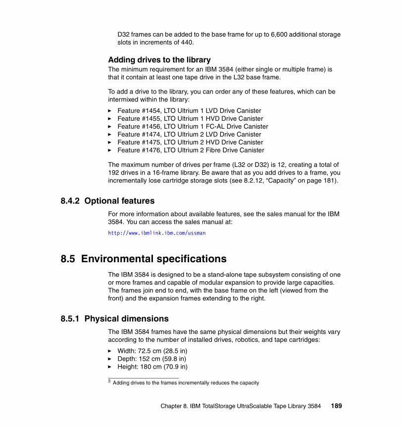
D32 frames can be added to the base frame for up to 6,600 additional storage slots in increments of 440.
Adding drives to the libraryThe minimum requirement for an IBM 3584 (either single or multiple frame) is that it contain at least one tape drive in the L32 base frame.
To add a drive to the library, you can order any of these features, which can be intermixed within the library:
� Feature #1454, LTO Ultrium 1 LVD Drive Canister� Feature #1455, LTO Ultrium 1 HVD Drive Canister� Feature #1456, LTO Ultrium 1 FC-AL Drive Canister� Feature #1474, LTO Ultrium 2 LVD Drive Canister� Feature #1475, LTO Ultrium 2 HVD Drive Canister� Feature #1476, LTO Ultrium 2 Fibre Drive Canister
The maximum number of drives per frame (L32 or D32) is 12, creating a total of 192 drives in a 16-frame library. Be aware that as you add drives to a frame, you incrementally lose cartridge storage slots (see 8.2.12, “Capacity” on page 181).
8.4.2 Optional featuresFor more information about available features, see the sales manual for the IBM 3584. You can access the sales manual at:
http://www.ibmlink.ibm.com/ussman
8.5 Environmental specificationsThe IBM 3584 is designed to be a stand-alone tape subsystem consisting of one or more frames and capable of modular expansion to provide large capacities. The frames join end to end, with the base frame on the left (viewed from the front) and the expansion frames extending to the right.
8.5.1 Physical dimensionsThe IBM 3584 frames have the same physical dimensions but their weights vary according to the number of installed drives, robotics, and tape cartridges:
� Width: 72.5 cm (28.5 in)� Depth: 152 cm (59.8 in)� Height: 180 cm (70.9 in)
3 Adding drives to the frames incrementally reduces the capacity
Chapter 8. IBM TotalStorage UltraScalable Tape Library 3584 189
Each frame has a set of casters and four leveling jackscrews. The nominal height from the bottom of the jackscrews to the top of the frame is 1840 mm (72.4 in), and can be varied by ±40 mm (±1.6 in). The shipping height of the IBM 3584 (on its casters and with jackscrews raised) is 1800 mm (70.9 in)
When planning for the installation, consider the space implications in your computer room for the possibility of adding more frames in the future.
� Weights4:
– IBM 3584-L32 with 1 drive, no cartridges: 423 kg (932 lb.)– IBM 3584-L32 with 12 drives, 227 cartridges: 570 kg (1256 lb.)– IBM 3584-D32 with no drives, no cartridges: 355 kg (784 lb.)– IBM 3584-D32 with 12 drives, 396 cartridges: 558 kg (1229 lb.)
8.5.2 Floor requirementsInstall the library on a raised or solid floor. The floor must have a smooth surface and, if raised, must not have ventilation panels beneath the leveling jackscrews. If carpeted, ensure that the carpet is approved for computer-room applications. To accommodate unevenness in the floor, you can raise or lower the leveling jackscrews to the following specifications:
� Maximum allowable variance must not exceed 7 mm (0.27 in) per 76 mm (3 in).
� Maximum out-of-level condition must not exceed 40 mm (1.6 in) over the entire length and width of the library.
The floor on which the library is installed must be able to support:
� Up to 4.8 kilograms per square cm (68.6 lb per square inch) of point loads exerted by the leveling jackscrews
� Up to 211 kilograms per square meter (43.4 lbs per square foot) of overall floor loading
The number of point loads exerted depends on the number of frames that make up the library. There are four point loads per frame (located at the corners of each frame).
4 The weight with cartridges assumes a cartridge weight of 0.209 kg (0.460 lb) for a standard cartridge. The actual weight of the library varies, depending on the configuration and cartridge capacity.
190 The IBM LTO Ultrium Tape Libraries Guide
8.5.3 Operating environmentThe IBM 3584 is designed to operate in the following environment:
� Temperature: 16o to 32o C (61o to 89o F)� Relative Humidity: 20% to 80%� Wet Bulb: 23o C (73.4o F) maximum
8.5.4 Power and cooling specificationsPower and cooling for the IBM 3584 components are provided by the housing frame. Each base and expansion frame that contains drives has its own frame control assembly (FCA), which receives power from a customer-supplied outlet and, in turn, provides AC power to all tape drives within the frame. The FCA for the L32 contains two DC power supplies; actually, only one DC power supply is needed to operate the entire library. Before support was provided for 16-frames, all additional FCAs in D32s included one additional DC power supply for redundancy. With support for 16-frames, the additional FCAs in the D-Frames no longer have a default-installed DC power supply.
Additional DC power supplies can nevertheless be ordered or made available for extra frames, as explained in 8.2.2, “Library control systems: frame control assembly” on page 167.
The FCA is not required in expansion frames that contain no tape drives.
Each frame receives single-phase (200-240 V ac) power on its own power cord from a customer-supplied outlet. Certain countries or regions require two-phase power to achieve the 200-240 V ac required by the frame. Countries in North America have the option of operating at 100-127 V ac power (FC 9951).
A new Dual AC Power feature (FC 1901), supporting either 110 V ac or 220 V ac, is available for the IBM 3584, providing two independent line cords that may be connected to two independent customer branch circuits. A power switch connects to one of two customer power feeds and passes all AC power to the frame from that feed. The switch monitors the AC line voltage from the feed it is using and automatically switches to the alternate AC power feed if the incoming voltage drops below a preset level.
Table 8-6 on page 192 lists the power requirements for the L32 and D32 frames.
Chapter 8. IBM TotalStorage UltraScalable Tape Library 3584 191

Table 8-6 Power requirements for the IBM 3584
8.6 Host platforms and device driversThe IBM 3584 is supported on many operating systems. For a current list of host software versions and release levels that support the 3584, refer to:
http://www.storage.ibm.com/tape/lto/3584/3584opn.pdf
The following no-charge specify codes indicate the server platform to which the IBM 3584 is attached. These features are used by IBM for device driver distribution:
� Feature #9210, attached to HP-UX� Feature #9211, attached to Sun System� Feature #9212, attached to Windows System� Feature #9213, attached to other non-IBM system� Feature #9215, attached to Linux System� Feature #9400, attached to iSeries System� Feature #9600, attached to pSeries
You are not limited to one platform-attach feature as the library may be attached to more than one of these platforms. You cannot add more than one of each feature; in other words, if you have two or more Windows servers, only one feature #9212 is required. The device driver will be delivered on a CD that contains all available device drivers for each OS and the documentation.
Power requirement Model L32 or D32
220 V ac line cord 110 V ac line cord
AC line voltage 200 to 240 V ac (nominal)
100 to 127 V ac (nominal)
AC line frequency 50 to 60 Hz 50 to 60 Hz
Nominal power 1.4 kW 1.2 kW
Line current 8.0 A 12.0 A
kVA 1.6 kVA 1.2 kVA
Heat output 4.8 kBtu/hr 4.1 kBtu/hr
Inrush current 200 A (peak for 1/2 cycle)
100 A (peak for 1/2 cycle)
Note: Values shown for frames with 12 IBM LTO Ultrium tape drives installed.
192 The IBM LTO Ultrium Tape Libraries Guide

8.6.1 Device driver installationInstall the IBM device drivers for the IBM 3584 as follows:
� If you intend to use the IBM 3584 with a commercial software application (such as IBM Tivoli Storage Manager, VERITAS Backup Exec, or Legato NetWorker), refer to that application’s installation instructions to install the device driver and configure the IBM 3584.
� If you do not intend to use the IBM 3584 with a commercial software application, install the tape and medium device driver from the CD that is shipped with the drive. Refer to the installation instructions in the IBM SCSI Tape Drive, Medium Changer, and Library Device Drivers Installation and User’s Guide, GC35-0154, which is supplied on the CD with the driver code.
8.7 Storage applicationsSoftware to exploit the IBM 3584 is not provided with the library. Additional software support is available through products that must be obtained separately from IBM, IBM Business Partners, or independent software vendors. A list of compatible software is available at:
http://www.storage.ibm.com/hardsoft/tape/conntrix/pdf/lto_isv_matrix.pdf
You will find details for each application including Ultrium 1 and Ultrium 2 support and specific Ultrium models and attachment methods. You should also contact your storage application vendor for more information about specific versions and platforms supported. Many examples of third-party software applications with IBM LTO drives and libraries are given in the Redbooks Implementing IBM LTO in
Tip: The device driver CD or diskette that is shipped with the IBM 3584 may not contain the most recent device drivers. Always check the following FTP site for the latest device drivers:
ftp://ftp.software.ibm.com/storage/devdrvr/
Note: If you use the IBM 3584 with a commercial software application, IBM recommends that you install any IBM-supplied device driver only if instructed to do so in the installation instructions supplied by the vendor of the application. Otherwise, if the application supplies its own driver code, then conflicts could occur over which driver controls the drive. Many examples are given in the Redbooks Implementing IBM LTO in Linux and Windows, SG24-6268, and Using IBM LTO Ultrium with Open Systems, SG24-6502.
Chapter 8. IBM TotalStorage UltraScalable Tape Library 3584 193

Linux and Windows, SG24-6268, and Using IBM LTO Ultrium with Open Systems, SG24-6502.
8.8 IBM 3584 initial setupThe following sections cover some of the major items required to implement, manage, and operate the IBM Ultrium tapes and libraries. We do not cover all tasks, and we do not intend to cover all of the specific commands. For more details, refer to the IBM 3584 UltraScalable Tape Library Planning and Operator Guide, GA32-0408.
8.8.1 SCSI IDThe IBM 3584 uses multi-path architecture, so it has no direct SCSI connection to a host system. When the host communicates with the library, it must send the communication via a control path to a drive designated as LUN 1. A control path is the drive SCSI port through which a host system sends its commands to a logical library within the IBM 3584. (Refer to 2.6, “Multi-path architecture” on page 46 for an explanation of the concept of logical libraries.) When you add multiple control paths to the IBM 3584 library, any single, configured logical library can be accessed by multiple host systems.
Additional control paths also reduce the possibility that failure in one control path will cause unavailability of the entire library.
8.8.2 Element numberElement numbers identify the physical location within the library. This information is required mostly for storage applications, such as IBM Tivoli Storage Manager, which translate the device to a name that the robotic understands.
In the IBM 3584, each SCSI storage element is assigned a SCSI element address. A SCSI storage element is a physical location capable of holding a tape cartridge (such as an I/O slot, drive, or storage slot). The element numbering is split into three sections:
� The tape drive sequence� The I/O station sequence� The cartridge slot sequence
Note: The setup and SCSI configuration of the IBM 3584 are usually performed by an IBM service representative.
194 The IBM LTO Ultrium Tape Libraries Guide
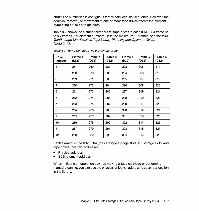
Note: The numbering is contiguous for the cartridge slot sequence. However, the addition, removal, or movement of one or more tape drives affects the element numbering of the cartridge slots.
Table 8-7 shows the element numbers for tape drives in each IBM 3584 frame up to six frames. For element numbers up to the maximum 16 frames, see the IBM TotalStorage UltraScalable Tape Library Planning and Operator Guide, GA32-0408.
Table 8-7 IBM 3584 tape drive element numbers
Each element in the IBM 3584 (the cartridge storage slots, I/O storage slots, and tape drives) has two addresses:
� Physical address� SCSI element address
When initiating an operation such as moving a tape cartridge or performing manual cleaning, you can use the physical or logical address to specify a location in the library.
Drive number
Frame 1 (L32)
Frame 2 (D32)
Frame 3 (D32)
Frame 4 (D32)
Frame 5 (D32)
Frame 6 (D32)
1 257 269 281 293 305 317
2 258 270 282 294 306 318
3 259 271 283 295 307 319
4 260 272 284 296 308 320
5 261 273 285 297 309 321
6 262 274 286 298 310 322
7 263 275 287 299 311 323
8 264 276 288 300 312 324
9 265 277 289 301 313 325
10 266 278 290 302 314 326
11 267 279 291 303 315 327
12 268 280 292 304 316 328
Chapter 8. IBM TotalStorage UltraScalable Tape Library 3584 195

The physical address consists of frame, column, and row identifiers that define a unique physical location in the library. The address is represented as:
� Fx,Cyy,Rzz for a storage slot (where F equals the frame and x equals its number, C equals the column and yy equals its number, and R equals the row and zz equals its number).
� Fx,Rzz for a tape drive and I/O storage slot (where F equals the frame and x equals its number, and R equals the row and zz equals its number).
The SCSI element address consists of a bit and hex value that defines to the SCSI interface a logical location in the library. This logical address is represented as xxxx (X'yyy'), where xxxx is a bit value and yyy is a hex value. It is assigned and used by the host when the host processes SCSI commands. The SCSI element address is not unique to a storage slot, drive, or I/O slot; it varies, depending on the quantity of drives in the library.
For example, the storage slot address F2,C03,R22 means:
� F2: frame 2 (first expansion frame)� C03: column 3 (second column from left on drive side)� R22: row 22 (22nd position down from the top of the column).
Each drive has a unique address to indicate its physical location. The drive address consists of two values, a frame number and a row number:
� Frame number: Represented as Fx, where F equals the frame and x equals its number. Regardless of whether any drives are installed, the frame number for the base frame is 1 and increments by one for each adjacent expansion frame.
� Row number: Represented as Rzz, where R equals the row and zz equals its number. The row number is 1 for the top drive position in the frame, and increments by one for each row beneath the top drive. Regardless of whether drives are installed, the row numbering is the same for every frame.
A drive address of F2,R10 means frame 2 (that is, the first expansion frame), row 10 (10th drive position from the top of the column).
8.9 Operator displays and buttonsThe IBM 3584-L32 operator display is a touch screen with integrated touch buttons. The display default setting will return to the basic main menu after five minutes of inactivity. The screen has three sections (Figure 8-19 on page 197):
� The menu title and panel number� The informational section� The selectable buttons
196 The IBM LTO Ultrium Tape Libraries Guide

Navigate through the operator panels by pressing the touch screen buttons:
� BACK:Will take you back to the previous screen. You may need to press the BACK button several times to return to the main status screen.
� UP and DOWN:If you are on a menu panel, these keys will navigate up and down within the current panel, scrolling one line when pressed once. If you keep the UP or DOWN keys pressed, scrolling will speed up. The longer you hold the keys, the faster will the scrolling be.
If you are selecting a value, the keys will increment or decrement the value.
� ENTER:The selected item is shown using reverse video. No action is processed until the ENTER key is pressed.
The default display is the Activity Status Display. The information in the Activity screen is replaced automatically by an error message whenever the Ultrium tape library detects that:
� A permanent error has occurred.� A drive requires cleaning, and automatic cleaning has been enabled.� A drive requires cleaning, and no cleaning cartridge is present in the library.
Figure 8-19 IBM 3584-L32 operator display
Other commands or options will appear on various screens. From the main activity screen, you can access the Library Main Menu by pressing the MENU key, or pause the library for maintenance operation with the PAUSE key.
Chapter 8. IBM TotalStorage UltraScalable Tape Library 3584 197

The PAUSE key causes the library to park the cartridge accessor in an area that gives clear access to the library’s interior (if you need to open the front door). If you accidentally press the PAUSE key, wait for the 30-second time-out. The library will automatically resume operation.
When selecting a critical command, such as pressing the PAUSE key, a confirmation screen will be displayed. You will see a text message with two keys, CONTINUE and CANCEL. The CONTINUE key will proceed and execute your command, and the CANCEL key will return to your previous screen.
The screens on the operator panel fall into six categories:
� Library status: Provides information about the accessor, the cartridge locations, the drives, and the slots.
� Manual operations: Enables manual intervention such as cartridge movements, cleaning, and inventory.
� Settings: Displays and changes configuration set-up variables such as cleaning mode, date, enabling/disabling of drives, and virtual library configuration.
� Statistics: Reports usage information about the accessor, drives, and cleaning cartridges.
� Vital Product Data (VPD): Describes the library, drives, and accessor.
This includes such information as the machine types, model numbers, serial numbers, and the level of firmware.
� Service: Places the library into service mode for repairs or upgrades to be carried out.
8.10 Sequential versus random accessThe IBM 3584 is designed to operate only in random mode under the control of a storage application. Sequential mode is not supported.
Attention: If you press the PAUSE key, then open the front door, the library rejects requests for new operations.
198 The IBM LTO Ultrium Tape Libraries Guide

Chapter 9. IBM xSeries LTO tape products
The xSeries Family of servers also features IBM Ultrium Libraries. Designed for tape automation, the IBM 3607-26X Autoloader and IBM 4560SLX Tape Library can be attached to xSeries servers and other Intel/Windows servers. They use the LTO Ultrium tape drives for faster data transfer and reliability in automated library service.
9
© Copyright IBM Corp. 2000, 2003. All rights reserved. 199

9.1 IBM 3607-26X and 4560-SLX
Figure 9-1 IBM 3607-26X Autoloader
The IBM 3607-26X Autoloader houses one Ultrium 1 tape drive with a native data transfer rate of 15 MBps and a cartridge capacity of 100 GB. The drives feature data compression hardware using an adaptation of the IBM LZ1 compression algorithm, which provides an effective data rate of up to 30MBps and a cartridge capacity of up to 200 GB (with 2:1 compression) on Ultrium 1 media.
The IBM 3607-26X has one I/O slot and a cartridge capacity of 16 slots, allowing a native capacity of 1.6 TB of uncompressed data. With compression (assuming 2:1), the 3607-26X can store 3.2 TB of data.
The IBM 3607-26X Autoloader is an excellent high-performance, entry-level choice for small to midrange systems.
Table 9-1 3607-26X Autoloader model summary
Model Cartridge slots
Data capacity (native)
Data capacity (compressed)
Ultrium 1 tape drives
3607-26X 16a
a. Plus one (1) I/O Station slot
1.6 TB 3.2 TB 1
200 The IBM LTO Ultrium Tape Libraries Guide
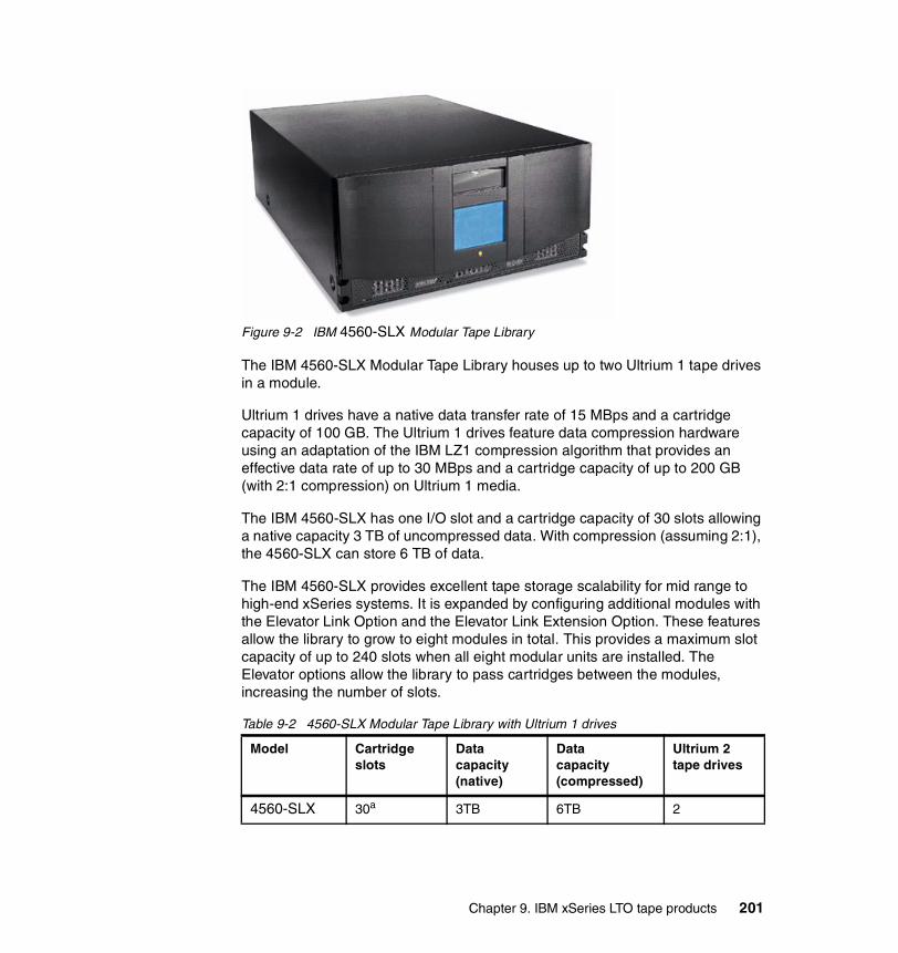
Figure 9-2 IBM 4560-SLX Modular Tape Library
The IBM 4560-SLX Modular Tape Library houses up to two Ultrium 1 tape drives in a module.
Ultrium 1 drives have a native data transfer rate of 15 MBps and a cartridge capacity of 100 GB. The Ultrium 1 drives feature data compression hardware using an adaptation of the IBM LZ1 compression algorithm that provides an effective data rate of up to 30 MBps and a cartridge capacity of up to 200 GB (with 2:1 compression) on Ultrium 1 media.
The IBM 4560-SLX has one I/O slot and a cartridge capacity of 30 slots allowing a native capacity 3 TB of uncompressed data. With compression (assuming 2:1), the 4560-SLX can store 6 TB of data.
The IBM 4560-SLX provides excellent tape storage scalability for mid range to high-end xSeries systems. It is expanded by configuring additional modules with the Elevator Link Option and the Elevator Link Extension Option. These features allow the library to grow to eight modules in total. This provides a maximum slot capacity of up to 240 slots when all eight modular units are installed. The Elevator options allow the library to pass cartridges between the modules, increasing the number of slots.
Table 9-2 4560-SLX Modular Tape Library with Ultrium 1 drives
Model Cartridge slots
Data capacity (native)
Data capacity (compressed)
Ultrium 2 tape drives
4560-SLX 30a 3TB 6TB 2
Chapter 9. IBM xSeries LTO tape products 201

9.1.1 Tape drivesThe 3607-26X uses one LTO Ultrium 1 tape LVD drive. The 4560-SLX can use up to two Ultrium 1 tape LVD drives per module. The drive part number is:
� Ultrium 1 Drive - P/N 59P6658
If Fibre Channel connectivity is required for the 4560-SLX, a Fibre Channel Card Adaptor (P/N 59P6657) can be installed into the library.
Each Ultrium tape drive contains the electronics and logic for reading and writing data, control of the tape drive, management of the data buffer, and error recovery procedures. All tape drives are packaged as a common assembly that is a Field Replaceable Unit (FRU), designed for quick removal and replacement.
9.1.2 Barcode readerA barcode reader is provided as standard with the 3607-26X and 4560-SLX, and it does not affect the slot capacity of the libraries. The barcode reader is used during the inventory process to locate all cartridges inserted in the library. This action is repeated every time the front door is opened to ensure that the inventory is updated if a cartridge has been manually added, moved, or removed while the door was open.
9.1.3 I/O stationThis facility allows the insertion and ejection of cartridges without interrupting the normal operation of the library. There is a single-slot I/O station where a cartridge can be inserted or ejected by opening the I/O station door.
4560-SLX with one expansion module
60 6TB 12TB 4
4560-SLX with seven expansion modules
240b 24TB 48TB 16
a. Plus one I/O Station slotb. Plus eight I/O station slots
Model Cartridge slots
Data capacity (native)
Data capacity (compressed)
Ultrium 2 tape drives
202 The IBM LTO Ultrium Tape Libraries Guide
9.1.4 Robotic systemIn conjunction with the library control microcode, the robotic system identifies and moves cartridges between the storage slots, tape drives, and the I/O station. It has several components:
� A cartridge picker for placing cartridges in storage slots, tape drives, or the I/O station
� A barcode reader used to set up the library initially when it identifies the types of media and tape drives installed in the library, and in normal operation for reading the external labels on the cartridges when it locates and categorizes all cartridges installed in the library
� X-axis and Z-axis drive motors for rotating the picker assembly, and moving it horizontally, inside the library enclosure
9.1.5 Library control and operationThe Library Control Unit contains the electronics and logic for autochanger and library operations. The Library Control Unit controls all operations in the library, including the interaction between the library and the operators. The control unit Licensed Internal Code creates and maintains the library configuration, the physical location of the robotic system, and the inventory of cartridges. The database is kept in the flash memory of the library control hardware.
Requests issued from the server result in cartridge movement in the library. The primary requests issued are for mounting and dismounting cartridges to and from the tape drives and for inserting and ejecting cartridges. The host has records of the physical location of a cartridge in the library, and the physical location is also managed by the library.
In addition to requesting movement of cartridges in the library, the host can obtain status, performance, and configuration information, as well as information about the cartridges stored in the tape library.
Each cartridge must have a machine- and operator-readable external barcode label to identify a media cartridge in the library during initial inventory and any time a cartridge is added to the library. The library stores the physical location of the cartridge in an inventory database based on the cartridge label. All host application requests for operations involving movement or use of a cartridge need only reference the physical location of the cartridge (using an element number as described in 9.9.1, “Identifying library locations element numbers” on page 207) for the library to perform the request.
Chapter 9. IBM xSeries LTO tape products 203
9.1.6 Operator panelAn LCD operator control panel on the front of the machine provides status information and menu options. From this panel the operator can initiate actions such as moving and loading tape cartridges or invoking diagnostics.
9.1.7 MaintenanceThe cartridge storage slots, cartridge picker, and tape drives are accessed for maintenance purposes by opening the front door of the library. The tape drives, power supplies, and host interface board are accessed from the back of the library for maintenance.
9.2 Library optionsThe following part numbers can be used to order features for the libraries (Table 9-3). We have not included the various cabling options. Refer to the product publications for detailed information about configuring and ordering the IBM Libraries, or visit:
http://www.pc.ibm.com/ww/eserver/xseries/tape.htm
Table 9-3 IBM 4560-SLX options
Option Description Comment
59P6657 IBM Fibre Channel Card Require either 59P1271 or 59P1272
59P6658 Ultrium 1 Drive LVD Connection
59P6659 LTO Cartridge Magazine Left and Right base magazines
59P6662 Elevator Link Required when adding a second module
59P6663 Elevator Link Extension Required when adding two or more modules
59P1271 Longwave GBIC To be used in conjunction with 59P6657
59P1272 Shortwave GBIC To be used in conjunction with 59P6657
49P3200 100GB Ultrium 1 Tape cartridge
204 The IBM LTO Ultrium Tape Libraries Guide

There are no additional part numbers required for the 3607-26X except the data cartridge 49P3200 and the Universal LTO Cleaning Tape 35L2086.
9.3 Physical attachmentsThe 4560-SLX Modular Tape Library and 3607-26X Autoloader can be attached to IBM xSeries servers and other Intel/Windows servers that support the SCSI LVD and Fibre Channel interface. Refer to the latest compatibility matrix to determine which xSeries servers support the libraries:
http://www.pc.ibm.com/us/compat/storage/tmatrix.html
SCSI cables and appropriate interposers, as required, should be ordered for attachment to a server. A power cord feature code should also be specified.
9.4 CablingA SCSI cable is required for each library connection to a SCSI bus. If no cable is available, one should be specified on the initial order for each library or drive. A SCSI terminator is included with each cable. An interposer (a connector that matches the pin pattern of the host adapter to the pin pattern of the cable) may also be required for attachment to particular server adapters.
Be sure to determine the exact SCSI connection type at the host to ensure that the correct cable connections are ordered, then determine the length from the host to the tape library.
The overall LVD SCSI cable length is limited to 25 m (81 feet) using point-to-point interconnection. If using multi-drop interconnection, then the overall LVD SCSI cable length is limited to 12 m (39 feet). The stub length at each device must not exceed 0.1 m (0.33 feet).
For FC cables, there are only two connection types, LC and SC. Once the connection type is determined then only a correct length has to be determined.
35L2086 Universal LTO Cleaning cartridge
Option Description Comment
Chapter 9. IBM xSeries LTO tape products 205

9.5 Environmental specificationsThe physical dimensions for the 4560-SLX are:
� Width: 42.4 cm (16.7 in)� Depth: 78.7 cm (31 in)� Height: 22.2 cm (8.75 in) for a stand-alone library on casters� 5 EIA units high (if rack-mounted)
The physical dimensions for the 3607-26Xare:
� Width: 44.7 cm (17.7 in)� Depth: 70.3 cm (29.7 in)� Height: 8.9 cm (3.5 in) for a stand-alone library on casters� 2 EIA units high (if rack-mounted)
9.6 Storage applicationsThe software to manage the tape libraries is not provided with the libraries. Additional software support is available through library management software products that must be obtained separately from IBM, IBM Business Partners, or independent software providers. Contact your vendor for information about support of xSeries tape products, or see the IBM ServerProven® Web site at:
http://www.pc.ibm.com/us/compat/
9.7 MediaOne Ultrium cleaning cartridge and one Ultrium data cartridge are included with each library drive order1. With the initial order, additional data and cleaning cartridges may be ordered as a part number.
� Part number 49P3200 provides a single Ultrium 1 Cartridge.� Part number 35L2086 provides a single Ultrium Cleaning Cartridge.
After the initial order, additional supplies can be ordered from the IBM media business or a third-party media vendor.
http://www.storage.ibm.com/media/index.html
Refer to Appendix A, “LTO Ultrium tape media” on page 223, for details about ordering supplies and cartridges, with or without labels.
1 All media and cleaning cartridges are warranted separately from the IBM 3580 Ultriumtape drive.
206 The IBM LTO Ultrium Tape Libraries Guide

9.8 Installation and performance considerationsInstalling more than one Ultrium drive on a SCSI bus may affect tape drive performance. For optimal performance, it is recommended that no more than one IBM Ultrium drive be attached to an individual SCSI bus.
While the IBM Ultrium tape drives provide the capability for high tape performance, other components of the system may limit the actual performance achieved. The compression technology used in the tape drive can typically double the amount of data that can be stored on the media; however, the actual degree of compression achieved is highly sensitive to the characteristics of the data being compressed.
9.9 Library featuresThe following section covers some of the major items required to implement, manage, and operate the IBM tape libraries. It does not cover all tasks and we do not intend to cover all of the specific commands. For more details, refer to the manual for your library listed in Table 9-6, “Library manuals” on page 211.
9.9.1 Identifying library locations element numbersTo manipulate the media within the library, the host must reference each movement with source and target designations. This is done via element addressing, which specifies precisely which slots within the library are to be used. Table 9-4 shows the element addressing scheme used for the 4560-SLX tape library.
Table 9-4 IBM 4560-SLX element numbering
Table 9-5 on page 208 shows the element addressing scheme used for the 3607-26X tape library.
Column Element numbers
Picker 0
I/O station 448
Drives 480-481
Storage 32-58
Chapter 9. IBM xSeries LTO tape products 207
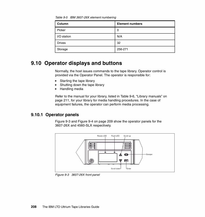
Table 9-5 IBM 3607-26X element numbering
9.10 Operator displays and buttonsNormally, the host issues commands to the tape library. Operator control is provided via the Operator Panel. The operator is responsible for:
� Starting the tape library� Shutting down the tape library� Handling media
Refer to the manual for your library, listed in Table 9-6, “Library manuals” on page 211, for your library for media handling procedures. In the case of equipment failures, the operator can perform media processing.
9.10.1 Operator panelsFigure 9-3 and Figure 9-4 on page 209 show the operator panels for the 3607-26X and 4560-SLX respectively.
Figure 9-3 3607-26X front panel
Column Element numbers
Picker 0
I/O station N/A
Drives 32
Storage 256-271
208 The IBM LTO Ultrium Tape Libraries Guide

Figure 9-4 4560-SLX touch screen front panel
The operator panel provides communication between the operator and the IBM tape library. Visual indications and push buttons enable the operator to control the tape library.
1. I/O Station status: The I/O Station status area provides constant information about the I/O Station.
2. Library status: The library status area displays information such as online or offline status, library reports status, and messages to solicit operator intervention.
3. Messages: The display communicates interactive dialogs, special messages, alerts, and library configurations. More details are covered in the operator manual.
4. Drive status: The drive status area provides constant information about the drives, such as:
– Presence of tape drive (illustrated by a black outline box for each drive)– Power to the tape drive– Cleaning requirements– Compression– Write protection– Tape activity
Chapter 9. IBM xSeries LTO tape products 209
9.10.2 Menu optionsEach menu is accessible through the Operator Panel push buttons. For the actual menus for your library, refer to the manual for your library listed in Table 9-6, “Library manuals” on page 211.
Using commands that require an offline stateSome commands require that the library be in an offline state. If any such commands are attempted while the library is in an online state, the operator will be requested to take the library offline.
Operator intervention messageIf a problem causes an operator intervention message to appear, refer to the messages section of your operator manual.
9.11 Library modesThe libraries operates in either base or random access mode. The Library Mode will be determined by the application software managing your library.
9.12 Drive cleaning All IBM Ultrium Tape Drives have an integrated cleaning mechanism which brushes the head at load time and again when unloading a cartridge. The drives also have a cleaning procedure that uses a special cleaning cartridge, should this become necessary.
With each library, a specially labeled IBM LTO Ultrium Cleaning Cartridge is supplied to clean the drive head. The drive determines and alerts you when the head needs to be cleaned. Refer to the operations manual for details for Automatic Cleaning or Manual Cleaning.
9.13 Firmware upgradesEach IBM Ultrium tape drive and tape library contains IBM Licensed Internal Code, often referred to as firmware. At installation time, make sure the current
Attention: When cleaning the drive head, use only the IBM LTO Ultrium Cleaning Cartridge or an IBM-approved cleaning cartridge.
210 The IBM LTO Ultrium Tape Libraries Guide
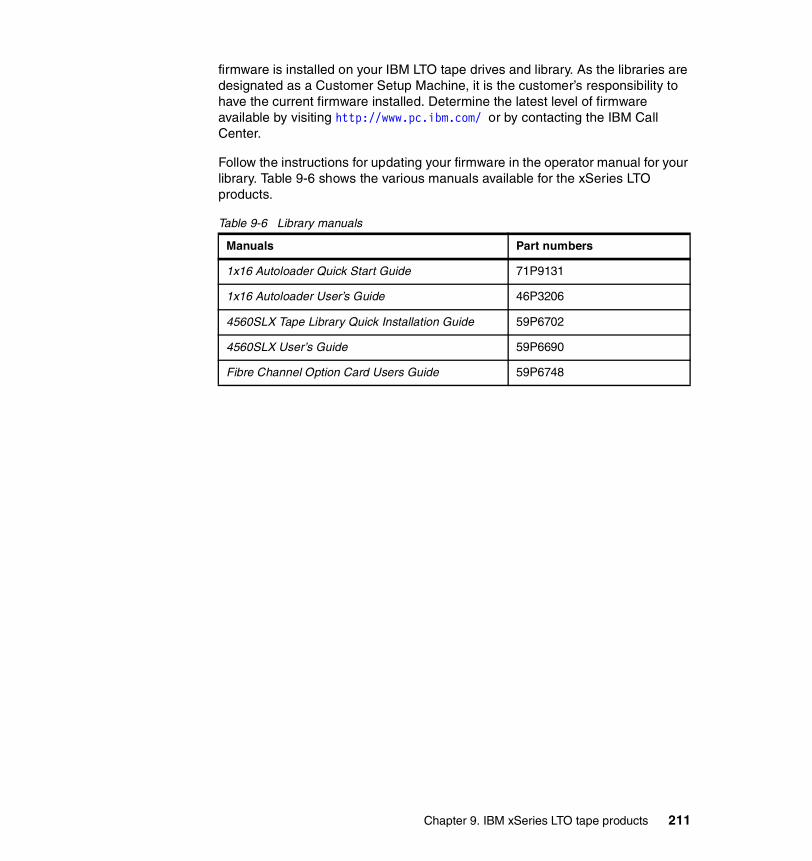
firmware is installed on your IBM LTO tape drives and library. As the libraries are designated as a Customer Setup Machine, it is the customer’s responsibility to have the current firmware installed. Determine the latest level of firmware available by visiting http://www.pc.ibm.com/ or by contacting the IBM Call Center.
Follow the instructions for updating your firmware in the operator manual for your library. Table 9-6 shows the various manuals available for the xSeries LTO products.
Table 9-6 Library manuals
Manuals Part numbers
1x16 Autoloader Quick Start Guide 71P9131
1x16 Autoloader User’s Guide 46P3206
4560SLX Tape Library Quick Installation Guide 59P6702
4560SLX User’s Guide 59P6690
Fibre Channel Option Card Users Guide 59P6748
Chapter 9. IBM xSeries LTO tape products 211

212 The IBM LTO Ultrium Tape Libraries Guide

Chapter 10. LTO and iSeries considerations
This is a short overview and update about installation and implementation of LTO Tape Drives and LTO Tape Libraries for iSeries.
A redbook and Redpaper address this topic:
� iSeries in Storage Area Networks, SG24-6220� The LTO Ultrium Primer for IBM iSeries Customers, REDP3580
However, these publications cover only LTO Ulrium 1, so we will provide updates and additional information.
10
© Copyright IBM Corp. 2000, 2003. All rights reserved. 213

10.1 iSeries support for IBM LTO Ultrium 2IBM LTO Ultrium 2 tape drives are supported on RISC machines with OS/400 V5R1 and later.
The following PTFs are needed:
� V5R1 SI07884� V5R2 SI07885
These PTFs fix a problem with the INZTAPcommand when using LTO 1 and 2 media in the same library.
You will need these V5R1 and V5R2 PTFs if you change the TAPF from its default density of *DEVTYPE. This is normally only done when using *NL tape label processing.
LTO 2 products can be attached to iSeries systems with any of these adapters:
� 6534 Magnetic Media Controller (SPD), HVD, HD68
Up to 17 MBps (60 GBph)
� 2729 PCI Magnetic Media Controller, HVD, HD68
Up to 13 MBps (47 GBph)
� 2749 PCI Ultra Magnetic Media Controller IOA, HVD, HD68
Up to 38 MBps (108 GBph)
� 5702 Ultra160 SCSI IOA PCI-X Ultra Tape Controller, LVD, VHDCI
Up to 70 MBps (250 GBph)
� 2765 FC IOAPCI Fibre Channel Tape Controller
Up to 95MBps (340 GBph)
Tip: Info APARs, periodically issued by IBM, contain important information about iSeries topics. There are currently two Info APARs about LTO: II12621 for Ultrium 1 and II13513 for Ultrium 2. These are available in the PTF database, from the Web site:
https://techsupport.services.ibm.com/server/support?view=iSeries
Look in the Find it Fast column, and choose Search Technical Databases. Leave the box at the top set at Search APARs, and click Go. Enter the Info APAR number in the search box and click Search.
214 The IBM LTO Ultrium Tape Libraries Guide
LTO 2 SCSI drives are supported with multiple drives connected to a single adapter (daisy-chained) for either the LVD or HVD adapters. The LTO 1 drives are still limited to a single-drive configuration.
The following restrictions apply:
� No support for LVD SCSI LTO 1 products on the 5702 adapter� No 6501 support for LTO 2
There is no performance increase with the HVD SCSI attached LTO 2 devices. Performance is limited by the HVD SCSI interface.
10.2 BRMS and LTO tape librariesBoth LTO 1 and LTO 2 drives can be in the same logical library and share a common inventory but you must not attach both drive types to the same I/O adapter. They must be separated at the adapter level for OS/400 to pool the drives together properly.
At the time of writing, OS/400 will show both the LTO 1 (L1 media type) and LTO 2 (L2 media type) as L so the user will not be able to determine from the WRKTAPCTG screen which cartridges are of which type.
OS/400 will NOT filter out the LTO 2 cartridges from the LTO 1 MLB so it is up to the user to manage the cartridges using BRMS media classes. The LTO 1 cartridges will have to be added to media class ULTRIUM1, and LTO 2 tapes will have to be added to media class ULTRIUM2. Attempting to use an LTO 2 cartridge in a LTO 1 drive will result in a failure.
For LTO 1 drives the density *CTGTYPE will result in *ULTRIUM1 for LTO 1 cartridges, and the density *DEVTYPE will result in *ULTRIUM1. LTO 2 cartridges are not supported in LTO 1 drives.
For LTO 2 drives the density *CTGTYPE will result in *ULTRIUM1 for LTO-1 cartridges and *ULTRIUM2 for LTO 2 cartridges. The density *DEVTYPE will only work for the LTO 2 drive with LTO 2 media, the device’s highest capability.
Chapter 10. LTO and iSeries considerations 215

10.3 iSeries resourcesThe iSeries can control drives and libraries through CL commands and APIs or through software such as BRMS/400. For V4R4 and later, LTO devices report as:
IBM 3580� 3580 tape drive:
– Resource -> 3580, Device Description -> TAPxx (xx=01, 02, 03, etc.)– 3580 002
IBM 3581� 3581 tape drive:
– Resource -> 3581, Device Description -> TAPxx (xx=01, 02, 03, etc.)– 3580 002
� 3581 Autoloader unit:– Resource -> 3581, Device Description -> TAPMLBxx (xx=01, 02, 03, etc.)
When the IBM 3581 is in random mode and an IPL is run for the system or IOP, a TAPMLBxx and TAPxx resource will be created. If the drive is in sequential mode and an IPL is run for the system or IOP, then only a TAPxx resource will be created (that is, the TAPMLBxx will be removed). If the drive normally is used in random mode, it can be changed to sequential mode. In this case, de-allocate the tape resource from the WRKMLBSTS command screen and vary on the tape drive to use as a standalone drive. Make sure the system has not run an IPL before changing the drive back to random mode. If the autoclean function is enabled or disabled, the IOP or IOA must run an IPL before using the 3581 device.
If the barcode feature is installed, the device is in random mode, and the drive is powered up with a cartridge loaded, the loaded cartridge will be missing when a WRKTAPCTG command is run on the iSeries. The cartridge has to be unloaded and the library re-inventoried to show the cartridge. If the 3581 is to be used as an alternate IPL device (as in a D Mode IPL), set the SCSI address on the tape device to 0.
Unloading volumes on IBM 3581When using the 3581 device in sequential mode, if a user selects the option Load Slot and SRC Slot to mount a volume in the drive (when using tape commands CHKTAP, DSPTAP, INZTAP, SAVxxx, with the ENDOPT(*UNLOAD)), the cartridge will eject from the drive but will not be returned to a slot. For this to happen, the user must specify SEQ START. Loading a slot is a manual operation and the autoloader will not return the cartridge, so it must be unloaded as it was loaded from the panel. The autoloader operation must be started to get the cartridges loaded and unloaded.
216 The IBM LTO Ultrium Tape Libraries Guide
IBM 3582� IBM 3582 tape drives:
– Resource -> 3582, Device Description -> TAPxx (xx=01, 02, 03, etc.)– 3580 002
� IBM 3582 Robotic:– Resource -> 3582, Device Description -> TAPMLBxx (xx=01, 02, 03, etc.)– 3582 023 with 3580 002 drives
IBM 3583� IBM 3583 tape drives:
– Resource -> 3583, Device Description -> TAPxx (xx=01, 02, 03, etc.)– 3580 001 and 3580 002
� IBM 3583 Robotic:– Resource -> 3583, Device Description -> TAPMLBxx (xx=01, 02, 03, etc.)– 3583 0xx with 3580 001 and 3580 002
3583 with SDG Fibre Channel limitationsThe 3583 device with FC 8005 (Fibre Channel attach) uses only LVD SCSI drives. V5R1 and later have Fibre Channel support. All FC attachments must be direct attached or homogeneous zones with iSeries only. The 3583 FC attached library has two Fibre Channel ports. The device can be shared with other platforms but it is strongly recommended that each platform be connected to separate ports. If zoning is used in the SAN device, be sure that the all iSeries hosts have a connection to the media changer. All six tape devices can be used but performance must be considered with the larger configuration. Alternate IPL is not supported for Fibre Channel attached tape devices. The Alternate Install Device (Boot Manager) must be used instead.
3583 non-multi-path architecture Fibre Channel recommendationsWhen sharing the 3583 FC with two or more hosts concurrently it may fail if the default time out for the initial mount wait time and the EOV mount wait time is used. These values have to be increased to a suggested 5-10 minutes. In general, larger library configurations and shared configurations tend to get a time-out error, so increasing this value is required.
IBM 3584� IBM 3584 Tape drives:
– Resource -> 3584, Device Description -> TAPxx (xx=01, 02, 03 etc.)� IBM 3584 Robotic:
– Resource -> 3584, Device Description -> TAPMLBxx (xx=01, 02, 03 etc.)– 3584 032 with 3580 001 and 3580 002 drives
Note: The Problem Analysis Log (PAL) will show 63A0 and 9429.
Chapter 10. LTO and iSeries considerations 217
Fibre Channel limitationsFor V5R1, the iSeries Fibre Channel 3584 support is limited to a single-drive configuration per adapter. Multiple systems may share a drive with the use of a 3534 Hub or 2109 switch. If the 2109 switch is used it must be set to Quick Loop mode for the ports used on the iSeries. Each system or LPAR may have multiple drives but each drive requires an adapter. Each drive connection must have a library control path enabled.
Alternate IPL is not supported for Fibre Channel attached tape devices.The Alternate Install Device (Boot Manager) must be used instead.
10.3.1 Configuration changesIf making any configuration changes on LTO drives and libraries you must run an IPL on the IOA/IOP on the iSeries.
10.4 OS/400 V5R1 restriction for multi-path architecture libraries
The IBM 3582, 3583, and 3584 feature multi-path architecture. Unlike other platforms, the iSeries requires a dedicated control path for each iSeries drive. This is true for both SCSI and fibre drives for OS/400 V5R1. This is not the way the library is shipped, so you have to enable the control paths on all drives that are connected to an iSeries. You can do this either on the operator panel or with StorWatch. If you forget to do this, the drives will not autoconfig properly.
If you have configured your library properly, then you will see as many tape libraries in OS/400 as there are tape drives are assigned to your server. For example, if you have a 3584 with three drives assigned to the iSeries, then you see three TAPMLBxx (TAPMLB01, TAPMLB02, TAPMLB03), each with three TAPxx (TAP01, TAP02, TAP03).
10.5 OS/400 V5R2Version 5 Release 2 includes support for multiple targets from a single Fibre Channel tape or disk adapter. Before this release, only a single target was supported from an initiator (FC adapter). Up to 16 LUNs are supported. A target is a physical tape drive. In the case of tape this means a single-tape FC adapter can support multiple tape devices. For example, with V5R1, if you had four iSeries with four FC tape devices, sixteen FC tape adapters would have been required to enable all iSeries to address all tape devices, as each FC adapter is
218 The IBM LTO Ultrium Tape Libraries Guide

allowed to see only one target. At V5R2 this number is reduced to four, one FC tape adapter per iSeries because each FC adapter may see multiple targets. This is illustrated in Figure 10-1. In summary, LTO 2 and V5R2 FC allow multiple device configurations per adapter and therefore one control path per adapter is required.
Figure 10-1 Multiple-target support
A maximum of 16 tape LUNs may be addressed from a single iSeries tape FC adapter. A LUN is a tape device or media changer. So in the case of a 3583 LTO tape library, which may have six drives and a media changer, seven LUNs will be reported. This example dramatically decreases the cost of hardware required to support multiple devices from multiple iSeries, but there are other considerations, such as management of tape devices.
Sharing the devices requires only a standard vary on and vary off command. When the iSeries varies on a tape it will use a reserve lock on the tape device to prevent other systems from using the drive. However, in a heterogeneous setup other operating systems may also share the drive. A benefit of the iSeries is its ability to reserve/release a tape drive. This prevents other systems writing to the middle of a tape in use by an iSeries and ensures tape data integrity for iSeries users. The same may not be true for other operating systems, and therefore it is entirely possible for an iSeries to start using a tape drive in use by another system. You will have to check with each vendor to establish whether they support reserve/release of a tape drive.
Tape management software such as BRMS and IBM Tivoli Storage Manager use the reserve lock. For other packages, check with the software vendor.
Chapter 10. LTO and iSeries considerations 219
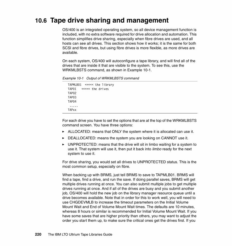
10.6 Tape drive sharing and managementOS/400 is an integrated operating system, so all device management function is included, with no extra software required for drive allocation and automation. This function simplifies drive sharing, especially when fibre drives are used, and all hosts can see all drives. This section shows how it works; it is the same for both SCSI and fibre drives, but using fibre drives is more flexible, as more drives are available.
On each system, OS/400 will autoconfigure a tape library, and will find all of the drives that are inside it that are visible to the system. To see this, use the WRKMLBSTS command, as shown in Example 10-1.
Example 10-1 Output of WRKMLBSTS command
TAPMLB01 <<<<< the libraryTAP01 <<<<< the drivesTAP02TAP03TAP04 .....TAPxx
For each drive you have to set the options that are at the top of the WRKMLBSTS command screen. You have three options:
� ALLOCATED: means that ONLY the system where it is allocated can use it.
� DEALLOCATED: means the system you are looking on CANNOT use it.
� UNPROTECTED: means that the drive will sit in limbo waiting for a system to use it. That system will use it, then put it back into limbo ready for the next system to use it.
For drive sharing, you would set all drives to UNPROTECTED status. This is the most common setup, especially on fibre.
When backing up with BRMS, just tell BRMS to save to TAPMLB01. BRMS will find a tape, find a drive, and run the save. If doing parallel saves, BRMS will get multiple drives running at once. You can also submit multiple jobs to get multiple drives running at once. And if all of the drives are busy and you submit another job, OS/400 will hold the new job on the library manager resource queue until a drive becomes available. Note that in order for this to work well, you will need to use CHGDEVMLB to increase the timeout parameters on the Initial Volume Mount Wait and End of Volume Mount Wait times. The defaults are 10 minutes, whereas 8 hours or similar is recommended for Initial Volume Mount Wait. If you have some saves that are higher priority than others, you may want to adjust the order you start them up, to make sure the critical ones get the drives first. If you
220 The IBM LTO Ultrium Tape Libraries Guide
make a mistake, then within each system, OS/400 will prioritize the jobs on the library manager resource queue, and at the next tape mount, it will swap out the job that was running, and move in the job with the higher tape resource priority.
Chapter 10. LTO and iSeries considerations 221

222 The IBM LTO Ultrium Tape Libraries Guide

Appendix A. LTO Ultrium tape media
When an IBM 35XX Ultrium tape device is ordered, it will be supplied with one Ultrium data cartridge and one cleaning cartridge at no charge. Each member of the IBM 35XX Ultrium LTO family has different media features and rules that apply when placing the order. The following informationwill assist you in ordering additional media.
You can obtain tape cartridge supplies for use with the IBM LTO Ultrium 1 product family in three ways:
� Order features from IBM that are available only with the initial hardware order as described in “Features available with IBM LTO hardware initial order” on page 225.
� Order the IBM LTO Ultrium 1 media product offering (using a dummy IBM model type, 3589) as described in “IBM 3589 Ultrium 1 tape cartridge model number” on page 228.
� Contact the IBM MEDIA business supplies or a third-party supplier as described in “IBM media business distributors and other suppliers” on page 231.
You can obtain tape cartridge supplies for use with the IBM LTO Ultrium 2 product family in two ways:
� Order features from IBM that are available only with the initial hardware order as described in “Features available with IBM LTO hardware initial order” on page 225.
A
© Copyright IBM Corp. 2000, 2003. All rights reserved. 223

� Contact the IBM MEDIA business suppliers or third-party suppliers as described in “IBM media business distributors and other suppliers” on page 231.
Each of the following additional media features for Ultrium 2 will supply data cartridges with barcode labels that are not fixed to the data cartridges. The barcode labels will have be physically attached and the actual value of barcode labels cannot be pre-determined. For cartridges with fixed barcode labels and pre-determined barcode values, it is recommended that the media always be ordered through 1-800-IBM-MEDIA (refer to “IBM media business distributors and other suppliers” on page 231).
The media suppliers may supply tape cartridges from different manufacturers or offer a choice of brands. The tape cartridges you use must be manufactured by a qualified LTO media company to meet the LTO standards.
224 The IBM LTO Ultrium Tape Libraries Guide
Features available with IBM LTO hardware initial orderThe following media features are available for inclusion with the initial hardware order.
IBM TotalStorage Ultrium 1 Tape Drive 3580These chargeable features provide media with the IBM 3580 Ultrium 1 tape drive and are available only with the initial order:
� Feature #8001 provides a single 100 MB Ultrium data cartridge with an unattached barcode label.
A maximum of five is allowed.
� Feature #8002 provides a single Ultrium cleaning cartridge.
A maximum of three is allowed.
In addition to these features, one Ultrium cleaning cartridge and one Ultrium data cartridge with a barcode are included as standard with each initial order1.
IBM TotalStorage Ultrium 2 Tape Drive 3580These chargeable features provide media with the IBM 3580 Ultrium 2 tape drive and are available only with the initial order:
� Feature #8101 provides a single 200 MB Ultrium data cartridge without an attached barcode label.
A maximum of 20 is allowed.
� Feature #8002 provides a single Ultrium cleaning cartridge.
A maximum of five is allowed.
In addition to these features, one Ultrium cleaning cartridge and one Ultrium data cartridge with a barcode are included as standard with each initial order.
IBM TotalStorage Ultrium Tape Library 3582These chargeable features provide media with the IBM 3582 tape library and are available only with the initial order:
� Feature #8001 provides a single 100 MB Ultrium data cartridge.
A maximum of 19 is allowed.
1 Note that all media and cleaning cartridges are warranted separately from the IBM 3580 tape drive hardware.
Appendix A. LTO Ultrium tape media 225

� Feature #8002 provides a single Ultrium cleaning cartridge.
A maximum of three is allowed.
� Feature #8110 provides a pack of twenty 100 MB Ultrium data cartridges with unattached barcode labels.
IBM TotalStorage Ultrium 1 Scalable Tape Library 3583These chargeable features provide media with the IBM 3583 Ultrium 1 tape library and are available only with the initial order:
� Feature #8001 provides a single 100 MB Ultrium data cartridge.
A maximum of 19 is allowed.
� Feature #8002 provides a single Ultrium cleaning cartridge.
A maximum of three is allowed.
� Feature #8010 provides a pack of twenty 100 MB Ultrium data cartridges with unattached barcode labels.
The maximum allowed for different model types is shown in Table A-1.
Table A-1 Maximum number of media features for IBM 3583 Ultrium 1
In addition to these features, one Ultrium cleaning cartridge and one Ultrium data cartridge with barcode are included as standard with each initial order2
IBM 3583 model #8007 (cartridge cells)
#8010(maximum allowed)
L18 0 1
L18 1 2
L18 2 3
L36 0 2
L36 1 3
L72 not applicable 4
2 Note that all media and cleaning cartridges are warranted separately from the IBM Ultrium hardware.
226 The IBM LTO Ultrium Tape Libraries Guide
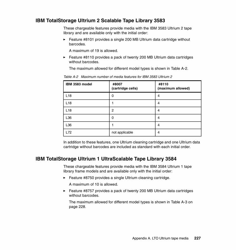
IBM TotalStorage Ultrium 2 Scalable Tape Library 3583These chargeable features provide media with the IBM 3583 Ultrium 2 tape library and are available only with the initial order:
� Feature #8101 provides a single 200 MB Ultrium data cartridge without barcodes.
A maximum of 19 is allowed.
� Feature #8110 provides a pack of twenty 200 MB Ultrium data cartridges without barcodes.
The maximum allowed for different model types is shown in Table A-2.
Table A-2 Maximum number of media features for IBM 3583 Ultrium 2
In addition to these features, one Ultrium cleaning cartridge and one Ultrium data cartridge without barcodes are included as standard with each initial order.
IBM TotalStorage Ultrium 1 UltraScalable Tape Library 3584These chargeable features provide media with the IBM 3584 Ultrium 1 tape library frame models and are available only with the initial order:
� Feature #8750 provides a single Ultrium cleaning cartridge.
A maximum of 10 is allowed.
� Feature #8757 provides a pack of twenty 200 MB Ultrium data cartridges without barcodes.
The maximum allowed for different model types is shown in Table A-3 on page 228.
IBM 3583 model #8007 (cartridge cells)
#8110(maximum allowed)
L18 0 4
L18 1 4
L18 2 4
L36 0 4
L36 1 4
L72 not applicable 4
Appendix A. LTO Ultrium tape media 227

Table A-3 Maximum number of media features for IBM 3584 Ultrium 1
In addition to these features, one Ultrium cleaning cartridge and one Ultrium data cartridge with barcode are included as standard with each initial Model L32 library order2.
IBM TotalStorage Ultrium 2 UltraScalable Tape Library 3584These chargeable features provide media with the IBM 3584 Ultrium 2 tape library frame models and are available only with the initial order:
� Feature #8767 provides a pack of twenty 200 MB Ultrium data cartridges without barcodes.
The maximum allowed for different model types is shown in Table A-4.
Table A-4 Maximum number of media features for IBM 3584 Ultrium 2
IBM 3589 Ultrium 1 tape cartridge model numberYou can use the IBM 3589 model number to order quantities of IBM LTO Ultrium 1 data and cleaning cartridges. Since this is not a true hardware machine type, engineering installation and maintenance are not relevant to it, no real serial number is applied to it (although cartridges have their own serial number types), and no MES features can be added to it once delivered.
Note there is no 3589 equivalent for Ultrium 2 tape cartridges.
IBM 3584model type
#1603(capacity expansion)
#8757(maximum allowed)
L32 (base) 0 1
L32 (base) 1 1
D32 (expansion) not applicable 1
IBM 3584model type
#1603(capacity expansion)
#8757(maximum allowed)
L32 (base) 0 1
L32 (base) 1 1
D32 (expansion) not applicable 1
228 The IBM LTO Ultrium Tape Libraries Guide

Model descriptionYou may choose from three model types for the IBM 3589, where each model delivers a different cartridge specification:
� IBM 3589-004 provides Ultrium cleaning cartridges.
Model 004 has a single chargeable feature, #4005, which indicates the required quantity of cleaning cartridges. Each feature delivers a pack of five cleaning cartridges. You must order at least one of these features for this model.
The maximum allowed is six features per model order for a total of 30 cartridges; if you require more than 30 cartridges, order a second 3589 model 004 with additional features.
� IBM 3589-003 provides Ultrium 1 data cartridges with no labels.
Model 003 has a single chargeable feature, #3020, which indicates the required quantity of unlabeled data cartridges. Each feature delivers a pack of 20 data cartridges. You must order at least one of these features for this model.
The maximum allowed is 20 features per model order (400 cartridges); if you require more than 400, order a second model 003 with additional features.
� IBM 3589-002 provides Ultrium 1 data cartridges with a labeling service.
Model 002 has a single chargeable feature, #2020, which indicates the required quantity of labeled data cartridges. As with the model 003, each feature delivers a pack of 20 data cartridges, and you must order at least one of these features for this model with a maximum of 20 features per model.
However, in addition, you must order various no-charge features to indicate what volume serial range you want printed on the cartridge labels. The supplied barcode label is made up of 8 characters, a six-character VOLSER, and a two-character cartridge media-type identifier (L1), which identifies the cartridge as an LTO cartridge (L) and indicates that the cartridge is the first generation of its type (1). The format of the VOLSER is explained in 2.3.4, “Volume label format” on page 23.
Labelling serviceThis service applies only to the IBM 3589 model 002.
There are six characters in the VOLSER, and IBM provides specific codes to allow you the flexibility to choose where to begin the volume range you require. The sixth character is always zero as your volume serial range must always begin at a 0 boundary for labeling, and the labels supplied are sequential. So, for
Appendix A. LTO Ultrium tape media 229

example, if you order 20 cartridges the first cartridge will be labeled with a sixth digit of 0, and the twentieth cartridge will be labelled with a sixth digit of 9.
The character identifier features are four-digit feature numbers of the form 9nnn, composed as follows:
� The first digit 9 means the feature carries no charge.
� A second digit of 1, 2, 3, 4, or 5 indicates which character in the VOLSER this feature is specifying (1st, 2nd, 3rd, 4th, or 5th).
� The third and fourth digits range from 00 through 35, where 00 through 09 represent the characters 1 through 9, and 10 through 35 represent the characters A through Z.
Choose the first 1, 2, 3, 4, or 5 digits by using the feature numbers as follows:
� First alphanumeric digit (0 to 9 or A to Z): use #9100 (0) to #9135 (Z).� Second alphanumeric digit (0 to 9 or A to Z): use #9200 (0) to #9235 (Z). � Third alphanumeric digit (0 to 9 or A to Z): #9300 (0) to #9335 (Z).� Fourth numeric digit (0 to 9): use #9400 (0) to #9409 (9).� Fifth numeric digit (0 to 9): use #9500 (0) to #9509 (9).� Sixth numeric digit is set to 0 as standard.� Seventh character of Volser is set to L.� Eighth character of Volser is set to 1.
If you do not specify a feature number then the supplied starting character will be zero. Thus if you specify features for the first thee characters as ABC but no more, then the sequence of labels will begin ABC000.
Two specific features indicate requirements for colored labels:
� Feature #9077 specifies a white background.� Feature #9022 specifies a colored background for the alpha characters.
If you specify #9022, then you can choose from 10 available colors shown in Table A-5 on page 231.
230 The IBM LTO Ultrium Tape Libraries Guide

Table A-5 Color specify feature codes for the IBM 3589 model 002
IBM media business distributors and other suppliersIf you want to buy additional supplies for the IBM LTO Ultrium product families you can obtain them from the IBM media business suppliers or third-party suppliers. To purchase in this way you must quote the Ultrium part numbers (not feature numbers or model types) for the different items required. The part numbers are listed in Table A-6.
Table A-6 LTO Ultrium 1 and 2 available supplies and part numbers
To obtain these supplies or for warranty replacements, use the appropriate distributor for your country location:
� United States and Canada: For information about Priority Fulfillment Services distribution channels call 1-888-IBM-MEDIA in the U.S. and Canada.
Alpha prefix background
Feature code Alpha prefix background
Feature code
red 9003 orange 9008
yellow 9004 pink 9009
light green 9005 dark green 9010
light blue 9006 light orange 9011
gray 9007 purple 9012
Part number Description
08L9120 IBM LTO Ultrium 1 data cartridge
08L9870 IBM LTO Ultrium 2 data cartridge (no barcode label)
19P5887 IBM LTO Ultrium 2 data cartridge (with barcode label)
35L2086 IBM LTO Ultrium cleaning cartridge
08L9129 Leader pin attachment kit
08L9130 Cartridge rewind tool
13F5647 IBM tape unit cleaner
2108930 Lint-free cloth
Appendix A. LTO Ultrium tape media 231

� Latin America: For information about Priority Fulfillment Services distribution channels call +1-972-881-0733.
� Asia Pacific:For information about Priority Fulfillment Services distribution channels call +81-3-3808-8486 in Japan or +1-972-881-0733 outside of Japan.
� Europe, Middle-East, and Africa:For information about Priority Fulfillment Services Europe distribution channels call +31-433-502-756.
� Other country-specific numbers can be found at:
http://www.storage.ibm.com/media/lto/index.html
.
232 The IBM LTO Ultrium Tape Libraries Guide

acronyms
AC Alternating Current
AIM Automatic Identification Manufacturers
AIT Advanced Intelligent Tape
AIX Advanced Interactive Executive
ALDC Adaptive Lossless Data Compression
AME Advanced Metal Evaporative
AMP Advanced Metal Evaporative
ANSI American National Standards Institute
API Application Programming Interface
ATF Auto Tracking Following
BRMS Business Recovery and Management Services
CM Cartridge Memory
CRC Cyclic Redundancy Check
CVE Compliance Verification Entity
DAT Digital Audio Tape
DC Direct Current
DDS Digital Data Standard
DLT Digital Linear Tape
ECC Error checking and correction
Abbreviations and
© Copyright IBM Corp. 2000, 2003. All rights reserved
ECMA European Computer Manufacturer’s Association
EEPROM Electrically Erasable Programmable Read-Only Memory
EOT End of tape
EOV End of volume
ESCON Enterprise Systems Connection
FC Fibre channel/feature code
FC-AL Fibre channel arbitrated loop
FCP Fibre channel protocol
FICON Fiber Connectivity
FRU Field replacable unit
HBA Host bus adapter
HSM Hierarchical storage management
HVD High voltage differential
IBM International Business Machines
IDRC Improved Data Recording Capability
IOP Input/output processor
ISV Industry solution provider
ITSO International Technical Support Organization
LAN Local area network
. 233

LGMR Laser Guided Magnetic Recording
LIP Loop initialization protocol
LPAR Logical partition
LPOS Longitudinal Positioning
LTO Linear Tape Open
LTO-CM Linear Tape Open-cartridge memory
LTO-DC Linear Tape Open Data Cartridge
LUN Logical unit number
LVD Low voltage differential
MCC Medium changer controller
MES Machine equipment specification
MFM Modified Frequency Modulation
MIB Management information block
MRC Magneto-Resistive Cluster
MTBF Mean time between failures
OEM Original equipment manufacture
P/N Part number
PCBA Printed circuit board assembly
PCI PC Connect interface
POS Pivoting Optical Servo
PRML Partial Response Maximum Likelihood
PTF Program temporary fix
QIC Quarter inch cartridge
RF Radio frequency
RLL Run Length Limited
RMU Remote Management Unit
SAN Storage Area Network
SARS Statistical Analysis and Reporting System
SCSI Small computer systems interface
SDG SAN Data Gateway
SDLT SuperDLT
SLDC Streaming lossless data compression
SMIT Systems Management Interface Tool
SNIA Storage Networking Industry Association
SNMP Simple Network Management Protocol
TCP/IP Transmission Control Protocol/Internet Protocol
VHDCI Very High Density Cable Interconnect
VPD Vital Product Data
WWN World Wide Name
234 The IBM LTO Ultrium Tape Libraries Guide

Related publications
The publications listed in this section are considered particularly suitable for a more detailed discussion of the topics covered in this redbook.
IBM RedbooksFor information about ordering these publications, see “How to get IBM Redbooks” on page 237. Note that some of the documents referenced here may be available in softcopy only.
� Storage Area Networks: Tape Future in Fabrics, SG24-5474
� Designing an IBM Storage Area Network, SG24-5758
� Using IBM LTO Ultrium with Open Systems, SG24-6502
� Implementing IBM LTO in Linux and Windows, SG24-6268
� IBM Tivoli Storage Manager Version 5.1 Technical Guide, SG24-6554
Other publicationsThese publications are also relevant as further information sources:
� IBM TotalStorage Tape Device Drivers Installation and User’s Guide, GC35-0154
� IBM TotalStorage Tape Device Drivers Programming Reference, GC35-0346
� IBM Ultrium Device Drivers Installation and User’s Guide, GA32-0430
� IBM 3580 Ultrium Tape Drive Setup, Operator, and Service Guide, GA32-0415
� IBM 3581 Ultrium Tape Autoloader Setup, Operator, and Service Guide, GA32-0412
� IBM 3582 Ultrium Tape Library Setup, Operator, and Service Guide, GA32-0548
� IBM 3583 Ultrium Scalable Tape Library Setup and Operator Guide, GA32-0411
� IBM 3584 UltraScalable Tape Library Planning and Operator Guide, GA32-0408
© Copyright IBM Corp. 2000, 2003. All rights reserved. 235

Online resourcesThese Web sites and URLs are also relevant as further information sources:
� This is the main Web site for information about IBM LTO products:
http://www.ibm.com/storage/lto
� The Linear Tape Open Technology Organization Web site provides information about the technology, formats and licensing:
http://www.lto-technology.com/
� The SCSI Trade Association Web site provides information about SCSI standards and terms:
http://www.scsita.org
� This Web site describes the media available from IBM:
http://www.ibm.com/storage/media
� This Web site describes IBM Microelectronics products including compression devices:
http://www.chips.ibm.com
� This Web site describes the Streaming Lossless Compression Algorithm:
http://www.ecma-international.org/publications/standards/ECMA-321.HTM
� IBM Tivoli Storage Manager SAN device support:
http://www-3.ibm.com/software/tivoli/products/storage-mgr-san/platforms.html
� Ultrium device driver downloads:
ftp://ftp.software.ibm.com/storage/devdrvr
� LTO devices update drive firmware:
http://ssddom02.storage.ibm.com/techsup/webnav.nsf/support/ltofaqs_updatefw_drivefw
� ISV Support Matrix for LTO:
http://www.storage.ibm.com/hardsoft/tape/conntrix/pdf/lto_isv_matrix.pdf
� Ultrium 3580 Drive firmware information:
http://www-1.ibm.com/support/docview.wss?rs=543&org=ssg&doc=S4000055&loc=en-us
� IBM 3582 Interoperability Matrix:
http://www.storage.ibm.com/tape/lto/3582/3582opn.pdf
� IBM 3583 Interoperability Matrix:
http://www.storage.ibm.com/tape/lto/3583/3583opn.pdf
236 The IBM LTO Ultrium Tape Libraries Guide

� IBM 3584 Interoperability Matrix:
http://www.storage.ibm.com/tape/lto/3584/3584opn.pdf
� IBM 3584 drive and library firmware:
ftp://ftp.software.ibm.com/storage/358x/3584
� IBM HBA and SAN Interoperability Matrix:
http://ssddom02.storage.ibm.com/hba/hba_support.pdf
� IBM Sales Manual:
http://www.ibmlink.ibm.com/ussman
� IBM ServerProven compatibility for hardware, applications, and middleware:
http://www.pc.ibm.com/us/compat
� IBM xSeries tape storage:
http://www.pc.ibm.com/ww/eserver/xseries/tape.html
� IBM iSeries technical support:
https://techsupport.services.ibm.com/server/support?view=iSeries
How to get IBM RedbooksYou can search for, view, or download Redbooks, Redpapers, Hints and Tips, draft publications and Additional materials, as well as order hardcopy Redbooks or CD-ROMs, at this Web site:
ibm.com/redbooks
Related publications 237

238 The IBM LTO Ultrium Tape Libraries Guide

Index
Numerics3580 see IBM 35803581 see IBM 35813582 see IBM 35823583 see IBM 35833584 see IBM 35848 mm tape 569210 1219211 1229212 1229400 1229600 122
Aactivity status display 197Advanced Metal Evaporative media 51AIT 57AIX commands
cfgmgr 176ALDC 16–17arbitrated loop 33archive life 25Atape driver 176autoloader 67automated tape libraries 68availability features 41
Bbackup 17bands 6, 10bands See also servo tracksbarcode
format 22barcode label 19barcode label format 22barcode reader 117, 132, 202brick 28
Ccall-home 179capacity 18capacity, calculation for IBM 3584 185
© Copyright IBM Corp. 2000, 2003. All rights reserved
cartridge door 19cartridge handling 25cartridge inspection 27cartridge life 24cartridge memory 7, 20, 42cartridge shipping 26cartridge slot columns 181cfgmgr 176channel calibration 38cleaning 43, 90, 111, 210
IBM 3580 91IBM 3582 128IBM 3583 156
cleaning cartridge 25, 43codewords 17coercivity 20common subassembly 28compression 16compression scheme swapping 30control path 46control path failover 47, 175
DDAT 54data bands 6, 13data compression 16, 30data rate 28, 50
burst 35–36data tracks
number of 16DDS 54diagnostic cartridge 182differential SCSI 32Digital Audio Tape 54Digital Data Standard 54Digital Linear Tape 58direction buffer 16disaster recovery 74DLT 58DLT 2000 60DLT 4000 60DLT 7000 61DLT 8000 61
. 239

dual-gripper 174dynamic speed matching 37
EEEPROM 20element addresses 194, 196element numbers 105, 194enterprise tape libraries 68error correction 7, 41
Ffast locate function 21FCA 169, 175, 191FC-AL 33Feature
1603 1887003 1007004 1008001 2258002 2258003 132, 1378004 132, 1378006 1428008 1428012 1418105 1329022 2309077 2309210 143, 1929211 143, 1929212 143, 1929213 143, 1929215 1439400 143, 1929600 143, 192
Fibre channel 33native 33
firmware 112, 179IBM 3580 91
flat lap head 42frame controller assembly see FCA
Ggrips 19
HHD68 34
helical-scan recording 50HVD 80, 95, 115, 132
II/O station 185IBM 113IBM 3480 63IBM 3490E 63IBM 3494 161IBM 3580 45, 79
application software support 86cartridges 87, 123, 206device driver 84–85display 89feature codes summary 81firmware 91implementation 87interposer 83L11 80media 87Model H11 80Model H23 80Model L11 80operating modes 110SCSI adapters 82SCSI cables 82SCSI ID 87SCSI length limitations 83server attachments 84status light 88Storage Applications 86unload 90upgrade 84warranty 81
IBM 3581 45, 93access mode 96activity bar 107barcode reader 98cartridge I/O 97cleaning 111control buttons 108device driver 102drive status 107error code 107feature codes summary 96general information 95Initial setup 104interposer 99
240 The IBM LTO Ultrium Tape Libraries Guide

library modes 96, 110media 87, 103media cartridges 103message display panel 106Model H17 95Model L17 95operator display 105optional bar code reader 100performance considerations 86, 103SCSI adapter 98SCSI cables 98SCSI devices 97setting SCSI addresses 104status light 105storage applications 103warranty 96
IBM 3582 45, 113application software support 123barcode reader 117capacity 114cleaning 128device driver 122element addresses 125feature codes summary 118firmware 128general information 114I/O station 117implementation 124interposer 121, 140inventory 117inventory update 117library control unit 117library modes 128magazines 115maintenance 118media 87, 123model description 114multi-path architecture 114, 124operator panel 118, 125–126performance considerations 124robotic system 117SCSI cabling 120SCSI defaults 125storage slots 115
IBM 3583 45, 129cabling options 138capacity 130cartridge magazines 133cleaning 156
control path 135device driver 144drive status 152, 209element addresses 150feature codes summary 136firmware 157general information 130I/O station 133, 141implementation 146inventory 132–133inventory update 132library control unit 133library mode 156library status 151magazines 132maintenance 135media 87, 145menu options 127, 153message display 151Model L18 131Model L36 131Model L72 131operator panel 134, 151performance considerations 145physical library layout 147redundant power 142Remote Management Unit 151, 154RMU 151, 154robotic system 133SAN Data Gateway 135SCSI adapters 137SCSI defaults 147SCSI ID and LUN assignment 146SDG 135storage columns 132upgrade 131, 141
IBM 3584 45, 159accessor 172bandwidth 187barcode reader 162, 174bulk-loading 162calibration sensor 174call-home 179capacity 160, 181capacity calculation 185Capacity Expansion feature 162cartridge gripper 173cartridge slots 163, 181components 165
Index 241

configuration 180control path 194control path failover 175D32 frame 183device drivers 192diagnostic cartridge 182distributed control system 167, 170drive features 166Dual AC Power 191dual-gripper 174element addresses 194, 196element numbers 194expansion frame 161, 188, 196features 188firmware 179floor requirements 190Frame Control Assembly Feature 163general information 160I/O station 162, 177, 185implementation 194inventory 186inventory time 188library control system 167logical address 196LTO Ultrium drives 166major components 165media 87mode of operation 198Model D32 161, 163, 188Model L32 161, 181multi-path architecture 134, 194operating environment 191operator display 196operator panel 171performance 186physical address 196physical dimensions 189pivot assembly 173power and cooling 191rail assembly 174reliability 177remote support 179Remote Support Attachment 179Remote Support Switch 179SNMP see SNMPStorWatch Specialist 176tape drive element numbers 195tape drives 162upgrade options 188
upgrades 188Vital Library Data 178Vital Product Data 198WWN 174
IBM 3607-26X 199barcode reader 202capacity 200element addresses 207feature codes 205firmware 210general information 200I/O station 202inventory 202library manuals 211library mode 210media 206menu options 210operator panel 208physical dimensions 206
IBM 4560-SLX 199, 208barcode reader 202capacity 201element addresses 207Elevator Link Extension Option 201Elevator Link Option 201feature codes summary 204firmware 210general information 201I/O station 202inventory 202library manuals 211library mode 210media 206menu options 210operator panel 208physical dimensions 206
IBM Magstar 3590 64IBM TotalStorage Enterprise Automated Library 3494 161IBM TotalStorage UltraScalable Tape Library 3584 see IBM 3584IBM TotalStorage Ultrium Tape Autoloader 3581 see IBM 3581IBM TotalStorage Ultrium Tape Drive 3580 see IBM 3580IBM TotalStorage Ultrium Tape Library 3582 see IBM 3582IBM TotalStorage Ultrium Tape Library 3582 see IBM 3582
242 The IBM LTO Ultrium Tape Libraries Guide

implementation 104, 124, 207IBM 3580 87
input/output station 162, 177integrated cleaning mechanism 90interchangeability of drives 45interfaces 31interleaved recording 10inventory 117, 132, 202
Llabel area 19labelling 229leader pin 19library centric WWN 175Library Control Unit 203library partitioning 47library sharing 46, 134library upgrade 45linear recording 6, 50Linear Tape Open
see LTOload-to-ready time 35–36locking mechanism 19logical library 134longitudinal positioning 12LPOS 13LTO 1
barcode 22cartridge life 24cartridge memory 20cleaning cartridge 25data compression 30formats 2interfaces 31inter-generation compatibility 39license packages 4licensing 3media identifier 23power supply 28reliability and availability 41shelf life 21specifications 3
LTO 2performance 36
LTO-CM 20, 24data fields 21
LTO-DC 16LVD 80, 95, 115, 132
Mmagazine numbering 148magazines 132–133Magstar 64maintenance 204Mammoth 57Management Information Base see MIBMCPmedia 223, 225
suppliers 231media compatibility 20media labelling 229Media sharing 72medium changer pack see MCPmetal particle media 20, 51MIB 180multi-path architecture 46, 114, 124, 134, 194multiple filemarks 38
NNetView 180notches 19
Ooffsite vaulting 74operating modes 110operator interface 170operator panel 118, 134, 204, 208
PPartial Response Maximum Likelihood 36PAUSE 197performance
load-to-ready 35–36search time 35–36unload time 35–36
physical address 195Pivoting Optical Servo 62POST 179power management 38Power On Self Test see POSTpower supply 28
QQIC 52QIC standards 54quarter-inch cartridge 52
Index 243

Rrandom access mode 110RAS 41, 177
IBM 3584 177read/verify elements 16, 29recording format 6Redbooks Web site 237
Contact us xxiiRemote Management Unit 134remote support 179Remote Support Attachment 179Remote Support Switch 179RMU 134robotic control 203
SSAN 68
Loop 71Point-to-point 71Server to server 69Server to storage 69Storage to storage 69Switched 71
SAN topologies 71SARS 21, 42scheme swap 17SCSI 31
adapter 82address for autoloader 97autoloader address 125cabling 205element address 196element numbers 105HVD differential 32LVD differential 32single ended 32
SCSI ID 87SDLT 62search time 35–36sequential access mode 110serpentine linear recording 51serpentine recording format 28Server-free backup 76servo
timing based 7servo bands 11servo bursts 11servo elements 30
servo tracks 10, 20, 51shelf life 25SNMP 180
MIB 180Sony AIT 57speed matching 37Statistical 42Statistical Analysis and Reporting System
see SARSstatus LED 39STK 9840 65StorWatch 176SuperDLT 62Surface Control Guiding 41switch
electronic head switch 29switch fabric connection 33
Ttape drive assembly 166tape format specifications 5tape head cleaner 41tape length 18tape media
coating 20material 20
threading mechanism 29Track Following 11tracks
number of 6positioning 7
TSMManaged System for SAN 75
UUltrium
capacity 6cleaning cartridge 43media 87media features 225recording format 6
Ultrium 1capacity 18interfaces 35number of tracks 6performance 35tape length 18
Ultrium 2
244 The IBM LTO Ultrium Tape Libraries Guide

capacity 18channel calibration 38interfaces 35media features 225multiple filemarks 38number of tracks 6performance 36power management 38speed matching 37tape length 18
Ultrium Cartridge 18Ultrium drive 28
display 39Ultrium tape 9universal cleaning cartridge 25unload time 35–36
VVHDCI 34volume label format 23volume serial number 22
Wwrap 14, 30write process 14write protect switch 24
Index 245

246 The IBM LTO Ultrium Tape Libraries Guide

(0.5” spine)0.475”<
->0.875”250 <
-> 459 pages
The IBM LTO Ultrium
Tape Libraries Guide


®
SG24-5946-01 ISBN 0738453226
INTERNATIONAL TECHNICALSUPPORTORGANIZATION
BUILDING TECHNICALINFORMATION BASED ONPRACTICAL EXPERIENCE
IBM Redbooks are developed by the IBM International Technical Support Organization. Experts from IBM, Customers and Partners from around the world create timely technical information based on realistic scenarios. Specific recommendations are provided to help you implement IT solutions more effectively in your environment.
For more information:ibm.com/redbooks
The IBM LTO Ultrium Tape Libraries Guide
Understand Linear Tape-Open technology and its unique architecture
Learn about the IBM Ultrium drives and libraries
Updated for Ultrium LTO 2 products
This IBM Redbook presents a general introduction to Linear Tape-Open (LTO) technology and the implementation of corresponding IBM products. As such it describes both general LTO technology specifications and specific details of the unique design of IBM Ultrium tape drives and libraries.
In addition to the description of LTO, the reader will find technical information about each of the IBM Ultrium products, including generalized sections about SCSI and Fibre Channel connections, multi-path architecture configurations, and tape technology comparisons with market positioning.
This book is intended for anyone who would like to understand more about the general LTO technology specification and how it came about, as well as the IBM implementation of that specification.
The second edition of this book covers the second generation LTO products as well as the original LTO products.
Back cover