IAPMO Green Plumbing and Mechanical Code … of 2015 GPMCS Proposals.pdfIAPMO Green Plumbing and...
40
IAPMO Green Plumbing and Mechanical Code Supplement (GPMCS) 2015 Proposed Changes for Public Comment 1 10/14/2014 Item Number Submitter Proposed Change Reason Statement GTC Action 1 Plumbing Water Efficiency TG Appendix D Vacuum Drainage Systems Add new Appendix D, Extracted from 2012 UPC Appendix C 7.0 A vacuum drainage systems allows for water reduction Accept as Submitted 2 Alternate Water Sources TG B103.2 Rainwater Catchment System Drainage Materials. Materials Gutters and downspouts used in rainwater catchment drainage systems shall comply with NSF Protocol P151 , including gutters, downspouts, conductors, and leaders and conductors shall be in accordance listed to NSF61 with the requirements of the plumbing code for storm drainage . Amends materials specific to the corresponding standard Accept as Submitted 3 Alternate Water Sources TG B 104.2 Minimum Water Quality. Upon initial system startup, the quality of the water for the intended applications shall be verified at the point(s) of use, as determined by the Authority Having Jurisdiction in accordance with Section B 104.2.1 and Section B 104.2.2 . B 104.2.1 Private Potable Water System. In the absence of water quality requirements determined by the Authority Having Jurisdiction, the minimum water quality for a private potable water system at the point of use shall comply with the following limits Table B104.2.1: Table B104.2.1 Minimum Water Quality Escherichia coli (fecal coliform): 99.9% reduction Non- detectable Protozoan Cysts: 99.99% reduction Non- detectable Viruses: 99.99% reduction Non- detectable Turbidity: <0.3 NTU B 104.2.2 Public Use Occupancies. The minimum water quality for a potable water system for public use occupancies at the point of use and testing procedures shall comply with the Environmental Protection Agency (EPA) Safe Drinking Water Act for a public water system. B 104.2.3 Maintenance . Normal system maintenance will shall require system testing every 3 months in accordance with Table B 104.2.3. System shall comply with the following standards Upon failure of the fecal coliform test, system shall be re-commissioned involving Amends the water quality reference as non- detectable according to EPA standards. Clarifies the use of the Table B104.2.1 for private potable water systems only. Public use occupancies must comply with EPA standard. Remaining edits are according to IAPMO Manual of Style. Accept as Submitted
Transcript of IAPMO Green Plumbing and Mechanical Code … of 2015 GPMCS Proposals.pdfIAPMO Green Plumbing and...

IAPMO Green Plumbing and Mechanical Code Supplement (GPMCS) 2015 Proposed Changes for Public Comment
1 10/14/2014
Item Number
Submitter Proposed Change Reason Statement GTC Action
1 Plumbing Water Efficiency TG
Appendix D Vacuum Drainage Systems Add new Appendix D, Extracted from 2012 UPC Appendix C 7.0
A vacuum drainage systems allows for water reduction
Accept as Submitted
2 Alternate Water Sources TG
B103.2 Rainwater Catchment System Drainage Materials. Materials Gutters and downspouts used in rainwater catchment drainage systems shall comply with NSF Protocol P151, including gutters, downspouts, conductors, and leaders and conductors shall be in accordance listed to NSF61 with the requirements of the plumbing code for storm drainage.
Amends materials specific to the corresponding standard
Accept as Submitted
3 Alternate Water Sources TG
B 104.2 Minimum Water Quality. Upon initial system startup, the quality of the water for the intended applications shall be verified at the point(s) of use, as determined by the Authority Having Jurisdiction in accordance with Section B 104.2.1 and Section B 104.2.2.
B 104.2.1 Private Potable Water System. In the absence of water quality requirements determined by the Authority Having Jurisdiction, the minimum water quality for a private potable water system at the point of use shall comply with the following limits Table B104.2.1:
Table B104.2.1 Minimum Water Quality
Escherichia coli (fecal coliform):
99.9% reduction Non-detectable
Protozoan Cysts: 99.99% reduction Non-detectable
Viruses: 99.99% reduction Non-detectable
Turbidity: <0.3 NTU
B 104.2.2 Public Use Occupancies. The minimum water quality for a potable water system for public use occupancies at the point of use and testing procedures shall comply with the Environmental Protection Agency (EPA) Safe Drinking Water Act for a public water system.
B 104.2.3 Maintenance. Normal system maintenance will shall require system testing every 3 months in accordance with Table B 104.2.3. System shall comply with the following standards Upon failure of the fecal coliform test, system shall be re-commissioned involving
Amends the water quality reference as non-detectable according to EPA standards. Clarifies the use of the Table B104.2.1 for private potable water systems only. Public use occupancies must comply with EPA standard. Remaining edits are according to IAPMO Manual of Style.
Accept as Submitted

IAPMO Green Plumbing and Mechanical Code Supplement (GPMCS) 2015 Proposed Changes for Public Comment
2 10/14/2014
Item Number
Submitter Proposed Change Reason Statement GTC Action
cleaning, and retesting in accordance with section B104.2.
Table B104.2.3 Minimum System Maintenance Requirements
Escherichia coli (fecal coliform):
99.9% reduction Non-Detectable
Turbidity: <0.3 NTU
a. Upon failure of the fecal coliform test, system shall be re-commissioned involving cleaning, and retesting in accordance with section B104.2.
b. One sample shall be analyzed for applications serving up to 1,000 persons. When the treated water shall serve 1,000-2,500 persons two (2) samples shall be analyzed and for 2,501-3,300 persons three (3) samples shall be analyzed
4 Staff B104.2.2 Disinfection Devices. Chlorination, ozone, and ultraviolet or
other disinfection methods shall be approved by an Authority Having Jurisdiction, or the product is shall be listed and certified according to a microbiological reduction performance standard for drinking water shall be used to treat harvested rainwater to meet the required water quality permitted. The disinfection devices and systems shall be installed in accordance with the manufacturer’s installation instructions and the conditions of listing. Disinfection devices and systems shall be located downstream of the water storage tank.
IAPMO Manual of Style edit Accept as Submitted
5 Alternate Water Sources TG
B104.4.1 Construction. Rainwater storage shall be constructed of solid, durable materials not subject to excessive corrosion or decay and shall be watertight. Storage tanks or storage tank liners and coatings shall be listed to NSF61 and approved by the Authority Having Jurisdiction for potable water applications, provided such tanks comply with approved applicable standards.
Adds the provision for liners that are listed to NSF 61.
Accept as Submitted
6 John Watson
204.0 Bottle Filling Station. A plumbing fixture that is connected to the potable water distribution and building drainage system that is designed and intended for filling personal use drinking water bottles or containers not less than 10 inches (250 mm) in height. Such fixtures can be separate from or integral to a drinking fountain and can incorporate a
New definition corresponding to new bottle filling station provisions proposed for Section 402.9
Accept as Submitted

IAPMO Green Plumbing and Mechanical Code Supplement (GPMCS) 2015 Proposed Changes for Public Comment
3 10/14/2014
Item Number
Submitter Proposed Change Reason Statement GTC Action
water filter and a cooling system for chilling the drinking water.
7 Gary Klein 204.0 Branch. A part of the piping system other than a main, riser, or stack.
New definition corresponding to new provisions proposed for Section 602.7
Accept as Submitted
8 Plumbing Water Efficiency TG
205.0 Condensate. Liquid water separated from a gaseous state due to changes in temperature or pressure, or both, and remains liquid at standard conditions.
New definition corresponding to new provisions proposed for Section 411.1
Accept as Submitted
9 Tom Pape 206.0 Dedicated Meter. A water measuring device used at a subsection or end use of a water supply system for any of the following purposes: billing, water management, collecting and analyzing water usage data, detection of leaks, equipment failure, water waste, and irregular or abnormal use for a specific application. Also called a submeter.
New definition corresponding to new provisions proposed for Section 409.1
Accept as Submitted
10 Irrigation TG
207.0 Evapotranspiration (ET). The combination of water transpired from vegetation and evaporated from the soil, water, and plant surfaces. Reference evapotranspiration (ETO) is calculated to produce maximum biomass based upon a cool-season grass 4-6 inches tall. Evapotranspiration rates are expressed in inches per day, week, month, or year. Evapotranspiration varies by weather conditions, including insolation, humidity, temperatures and wind. climate and time of year. Common usage includes reference evapotranspiration as the base rate (water demand of 4-6 inch tall cool season grass), modified with coefficients or factors for specific plant types. Modified Eevapotranspiration rates are used as a factor in estimating the irrigation water needs of landscapes. Local agriculture extension, state departments of agriculture, water agencies, irrigation professionals, the United States Geological Survey, and internet websites are common sources for obtaining local Eevapotranspiration rates.
Amended language enhances the definition by distinguishing the nuances of this term.
Accept as Submitted
11 Plumbing Water Efficiency TG
209.0 Gang Showers (Non-Residential). Shower compartments designed and intended for use by multiple persons simultaneously in non-residential occupancies.
Removed non-residential reference as non-essential to the definition.
Accept as Submitted
12 HVACR TG 209.0 Ground Source Heat Pump. A heat pump that uses the thermal energy of the ground or groundwater to provide space conditioning or water heating.
New definition corresponding to new provisions proposed for Section 705.1.4.1
Accept as Submitted

IAPMO Green Plumbing and Mechanical Code Supplement (GPMCS) 2015 Proposed Changes for Public Comment
4 10/14/2014
Item Number
Submitter Proposed Change Reason Statement GTC Action
13 Irrigation
TG 211.0 Irrigation Demand. The amount of irrigation water not supplied by natural precipitation that is needed to maintain landscape plant life in good condition. Irrigation demand is calculated by subtracting natural effective precipitation from the ET rate adjusted by the crop landscape coefficient which includes the functional purpose and desired quality of the plant being irrigated
Amends the definition for better clarity Accept as Submitted
14 Irrigation TG
211.0 Irrigation Control System. An irrigation control system consists of a combination of a programmable controller using one or more inputs or sensors that, in combination, estimate or measure the availability of moisture for plants in order to operate an irrigation system, in such a manner that the system replenishes water as needed while minimizing excess water use. A properly programmed irrigation control system requires initial site specific set-up and will make irrigation schedule adjustments, including run times and required cycles throughout the irrigation season without human intervention.
New definition corresponding to the heading title for Section 413.4
Accept as Submitted
15 Staff 214.0 Lavatory. 1) a basin or vessel, for washing. 2) a plumbing fixture, as above defined in (1), especially placed for use in personal hygiene. Principally not used for laundry purposes and never used for food preparation, or utensils, in food services. 3) a fixture designed for the washing of the hands and face. Sometimes called a wash basin.
Manual of Style edit Accept as Amended
16 Gary Klein 215.0 Main. The principal artery of a system of continuous piping to which branches may be connected.
New definition corresponding to new provisions proposed for Section 413.13.1.1
Accept as Submitted
17 GTC 217.0 On-Site Treated Nonpotable Water. Nonpotable water, that has been collected, treated, and intended to be used onsite and is suitable for direct beneficial use. Sources for onsite treated nonpotable water include but are not limited to gray water; black water; rainwater; stormwater; reclaimed (recycled) water; swimming pool backwash; condensate; cooling tower blow-down water; foundation drainage; fluid cooler discharge water; food steamer discharge water; combination oven discharge water; industrial process water; fire pump test water and dry weather runoff.
Committee decided to refrain from creating lists and to remove all language except first sentence.
Accept as Amended
18 Michael Ivanovich
218.0 Power Roof/Wall Ventilator (PRV). A fan consisting of a centrifugal or axial impeller with an integral driver in a weather-resistant
New definition corresponding to new provisions proposed for Section 703.5.3.1.3
Accept as Submitted

IAPMO Green Plumbing and Mechanical Code Supplement (GPMCS) 2015 Proposed Changes for Public Comment
5 10/14/2014
Item Number
Submitter Proposed Change Reason Statement GTC Action
housing and with a base designed to fit, usually by means of a curb, over a wall or roof opening.
19 Alternate Water Sources TG
218.0 Public Water System. A system for the provision to the public of water for human consumption through pipes or other constructed conveyances, if such system has at least fifteen service connections or regularly serves an average of twenty-five individuals daily for at least 60 days per year.
EPA definition corresponding to new provisions proposed for Section B104.2.2
Accept as Submitted
20 Alternate Water Sources TG
220.0 Rainwater. Natural precipitation that has contacted a rooftop or other man-made above ground surface and has not been put to beneficial use.
Removed a non-essential element to the definition.
Accept as Amended
21 Plumbing Water Efficiency TG
220.0 Reverse Osmosis Reject Water. Water that does not pass through a membrane of a reverse osmosis system.
New definition corresponding to revised Section 415.0
Accept as Submitted
22 Alternate Water Sources TG
221.0 Stormwater. Natural precipitation that has contacted a surface at grade, or below grade, or above ground parking surfaces and has not been put to beneficial use.
Removed a non-essential element to the definition and added a new element
Accept as Amended
23 Alternate Water Sources TG
221.0 Storage Tank (rainwater, stormwater or dry weather runoff). The central component of the rainwater, stormwater or dry weather runoff catchment system used for storing water at atmospheric pressure. Also known as a cistern or rain barrel.
Widened the range of applicability in the definition. Accept as Amended
24 John Roth 304.1 Disposal. It shall be unlawful for any person to cause, suffer, or permit the disposal of sewage, human excrement, or other liquid wastes, in any place or manner, except through and by means of an approved drainage system, installed and maintained in accordance with the provisions of the plumbing code and this supplement. Exception: Composting toilets
To resolve conflict between existing code and new section on Composting Toilets.
Accept as Submitted
25 John Roth 304.2 Connections to Plumbing System Required. Plumbing fixtures, drains, appurtenances, and appliances, used to receive or discharge liquid wastes or sewage, shall be connected properly to the drainage system of the building or premises, in accordance with the requirements of the plumbing code and this supplement. Exception: Composting toilets
To resolve conflict between existing code and new section on Composting Toilets.
Accept as Submitted

IAPMO Green Plumbing and Mechanical Code Supplement (GPMCS) 2015 Proposed Changes for Public Comment
6 10/14/2014
Item Number
Submitter Proposed Change Reason Statement GTC Action
26 Stuart
Mann, Water Quality Association, Lisle, IL
306.0 Drinking Water Treatment Systems. Drinking water treatment systems shall be listed to WQA/ASPE/ANSI S-803. 307.0 Life Cycle Assessment. Drinking water treatment systems shall be listed to the life cycle assessment requirements specified in WQA/ASPE/ANSI S-803. Chapter 11 - Referenced Standards
Standard Number - Year
Standard Title Reference Section
WQA/ASPE/ANSI 803 - 2014
Sustainable Drinking Water Treatment Systems
306.0, 307.0
Despite the presence of existing safety/performance standards (i.e. NSF/ANSI 42 and NSF/ANSI 53), up to this point, no sustainability standards have existed for drinking water treatment products. The Water Quality Association (WQA) partnered with PE INTERNATIONAL Inc. (PE) to assemble a team of manufacturers, component suppliers, industry experts and other key stakeholders, tasked with the development of a voluntary product sustainability standards for the water products industry, in order to improve the overall sustainability of this sector. WQA has also now partnered with the American Society of Plumbing Engineers (ASPE) to take this standard through the ANSI accreditation process. This standard has been developed by the WQA for drinking water contact products. The overall goal of this standard is to provide meaningful product sustainability performance information to consumers and stakeholders and to drive innovation and continual improvement in the sustainability performance of these products. The purposes of the WQA S-803 are as follows: A. Encourage more strategic participation among product manufacturers for the advancement of sustainable products and business practices through improvements in the areas of product design, manufacture and production site management, distribution, disposal, etc.; B. Facilitate this enhanced focus on Sustainability to leverage increased competitiveness in the market for products which qualify under these standards. C. Develop a streamlined series of standards that allows for evaluation of drinking water treatment products based on product categories, as well as the environmental performance of entire production facilities, as opposed to evaluating all
Accept as Amended GTC struck out Section 307.0 as redundant
IAPMO Green Plumbing and Mechanical Code Supplement (GPMCS) 2015 Proposed Changes for Public Comment
7 10/14/2014
Item Number
Submitter Proposed Change Reason Statement GTC Action
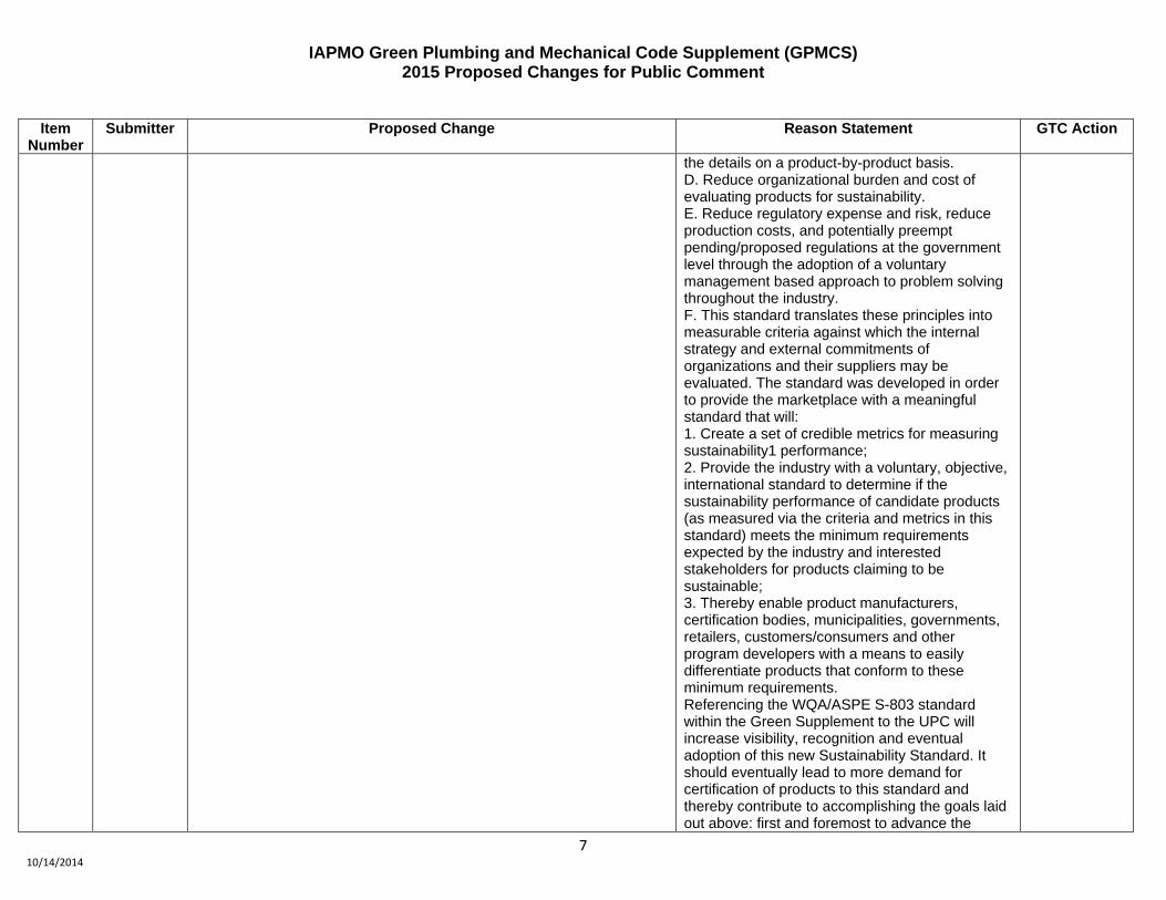
the details on a product-by-product basis. D. Reduce organizational burden and cost of evaluating products for sustainability. E. Reduce regulatory expense and risk, reduce production costs, and potentially preempt pending/proposed regulations at the government level through the adoption of a voluntary management based approach to problem solving throughout the industry. F. This standard translates these principles into measurable criteria against which the internal strategy and external commitments of organizations and their suppliers may be evaluated. The standard was developed in order to provide the marketplace with a meaningful standard that will: 1. Create a set of credible metrics for measuring sustainability1 performance; 2. Provide the industry with a voluntary, objective, international standard to determine if the sustainability performance of candidate products (as measured via the criteria and metrics in this standard) meets the minimum requirements expected by the industry and interested stakeholders for products claiming to be sustainable; 3. Thereby enable product manufacturers, certification bodies, municipalities, governments, retailers, customers/consumers and other program developers with a means to easily differentiate products that conform to these minimum requirements. Referencing the WQA/ASPE S-803 standard within the Green Supplement to the UPC will increase visibility, recognition and eventual adoption of this new Sustainability Standard. It should eventually lead to more demand for certification of products to this standard and thereby contribute to accomplishing the goals laid out above: first and foremost to advance the

IAPMO Green Plumbing and Mechanical Code Supplement (GPMCS) 2015 Proposed Changes for Public Comment
8 10/14/2014
Item Number
Submitter Proposed Change Reason Statement GTC Action
sustainability achievement levels within the Water Treatment Products industry. Documents provided: WQA S-801: Sustainable Management and WQA/ASPE S-803: Sustainable Drinking Water Treatment Systems
27 Food Waste TG
307.0 Food Waste Devices. Where food waste devices exist they shall meet the following requirements: 307.1 Pulpers and Mechanical Strainers. The water use for the pulpers or mechanical strainers shall not exceed 2 gpm. A flow restrictor shall be installed on the water supply to limit the water flow. 307.2 Food Waste Disposers. The water use for the food waste grinder shall not exceed the 8 gpm under full load condition and 1 gpm under no-load condition. Flow restrictors shall be installed on the water supply to limit the water flow rate to a maximum of 8 gpm. A load sensing device shall be installed to monitor current demand and regulate water flow. 307.3 Time Out and Shut Off. Pulpers, mechanical strainers, and food waste disposers shall have a time out system with push button to reactivate. The maximum allowable run time cycle shall be 10 minutes. 307.4 Sink Drain Outlets. Where a strainer or basket is installed they shall be readily removable. 307.5 Strainer Baskets. Strainer (scrapper) baskets shall either fit over a sink compartment or be attached to a drain system. The strainer baskets shall be readily removable for emptying.
New provisions for food waste devices. Accept as Submitted
28 John Roth 402.3.1 Nonwater Urinals. Nonwater urinals shall comply with ASME A112.19.3/CSA B45.4, ASME A112.19.19/CSA B45.4 or IAPMO Z124.9. Nonwater urinals shall be cleaned and maintained in accordance with the manufacturer’s instructions after installation. Where nonwater urinals are installed they shall have a water distribution line roughed-in to the urinal location at a height not less than 56 inches (1422 mm) above finished floor to allow for the installation of an approved backflow prevention device in the event of a retrofit. Such water distribution lines shall be installed with shutoff valves located as close as possible to the distributing main to prevent the creation of dead ends. Where nonwater urinals are installed, not less than one water supplied fixture rated at not less than 1 drainage fixture unit (DFU) shall be installed upstream on the same
To resolve conflict between existing code and new section on Composting Toilets.
Accept as Submitted
IAPMO Green Plumbing and Mechanical Code Supplement (GPMCS) 2015 Proposed Changes for Public Comment
9 10/14/2014
Item Number
Submitter Proposed Change Reason Statement GTC Action
drain line to facilitate drain line flow and rinsing. Exception: Non water urinals used as part of a composting toilet system.
29 Plumbing Water Efficiency TG
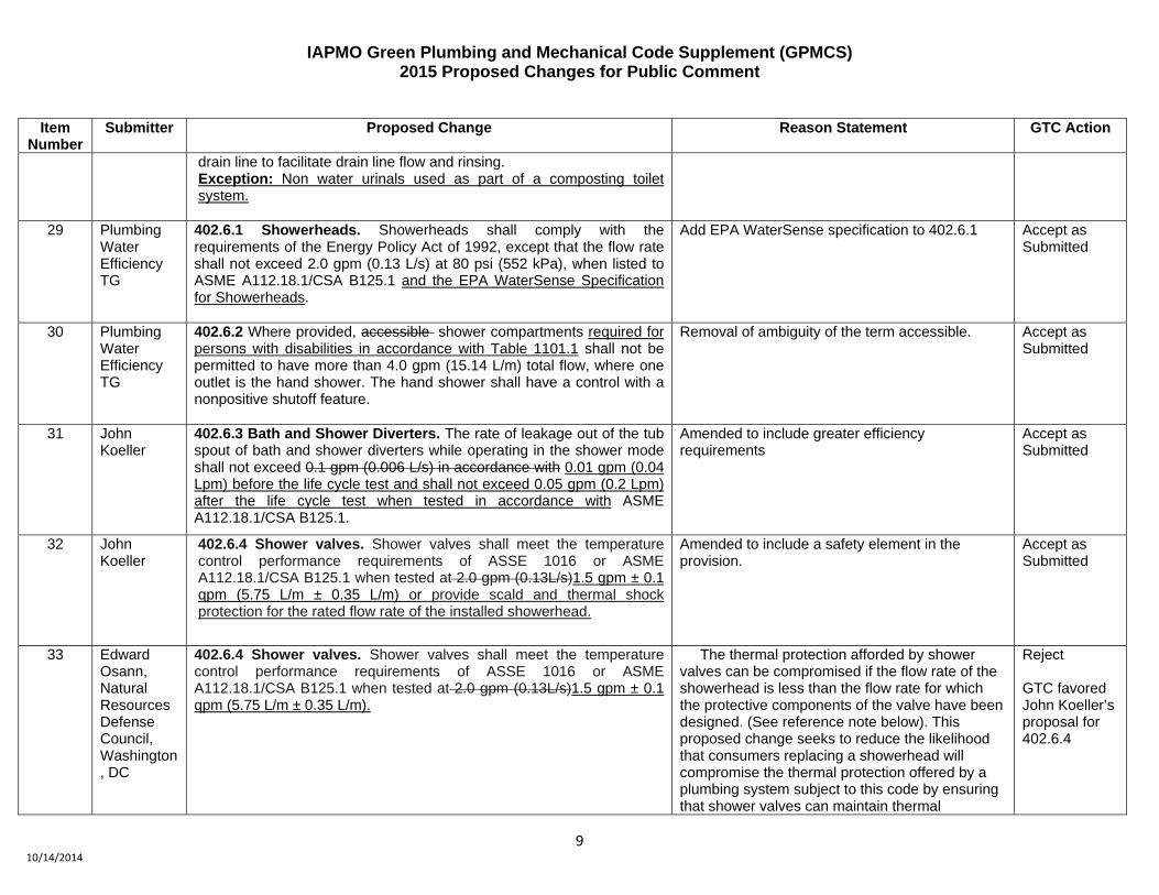
402.6.1 Showerheads. Showerheads shall comply with the requirements of the Energy Policy Act of 1992, except that the flow rate shall not exceed 2.0 gpm (0.13 L/s) at 80 psi (552 kPa), when listed to ASME A112.18.1/CSA B125.1 and the EPA WaterSense Specification for Showerheads.
Add EPA WaterSense specification to 402.6.1
Accept as Submitted
30 Plumbing Water Efficiency TG
402.6.2 Where provided, accessible shower compartments required for persons with disabilities in accordance with Table 1101.1 shall not be permitted to have more than 4.0 gpm (15.14 L/m) total flow, where one outlet is the hand shower. The hand shower shall have a control with a nonpositive shutoff feature.
Removal of ambiguity of the term accessible. Accept as Submitted
31 John Koeller
402.6.3 Bath and Shower Diverters. The rate of leakage out of the tub spout of bath and shower diverters while operating in the shower mode shall not exceed 0.1 gpm (0.006 L/s) in accordance with 0.01 gpm (0.04 Lpm) before the life cycle test and shall not exceed 0.05 gpm (0.2 Lpm) after the life cycle test when tested in accordance with ASME A112.18.1/CSA B125.1.
Amended to include greater efficiency requirements
Accept as Submitted
32 John Koeller
402.6.4 Shower valves. Shower valves shall meet the temperature control performance requirements of ASSE 1016 or ASME A112.18.1/CSA B125.1 when tested at 2.0 gpm (0.13L/s)1.5 gpm ± 0.1 qpm (5.75 L/m ± 0.35 L/m) or provide scald and thermal shock protection for the rated flow rate of the installed showerhead.
Amended to include a safety element in the provision.
Accept as Submitted
33 Edward Osann, Natural Resources Defense Council, Washington, DC
402.6.4 Shower valves. Shower valves shall meet the temperature control performance requirements of ASSE 1016 or ASME A112.18.1/CSA B125.1 when tested at 2.0 gpm (0.13L/s)1.5 gpm ± 0.1 qpm (5.75 L/m ± 0.35 L/m).
The thermal protection afforded by shower valves can be compromised if the flow rate of the showerhead is less than the flow rate for which the protective components of the valve have been designed. (See reference note below). This proposed change seeks to reduce the likelihood that consumers replacing a showerhead will compromise the thermal protection offered by a plumbing system subject to this code by ensuring that shower valves can maintain thermal
Reject GTC favored John Koeller’s proposal for 402.6.4

IAPMO Green Plumbing and Mechanical Code Supplement (GPMCS) 2015 Proposed Changes for Public Comment
10 10/14/2014
Item Number
Submitter Proposed Change Reason Statement GTC Action
protection for bathers using WaterSense labeled showerheads with flow rates lower than the current maximum WaterSense specification of 2.0 gpm. Showerheads with maximum flow rates below 2.0 gpm are widely available on the market today, and simple replacement of a showerhead is typically not subject to code. Since shower valve components are located behind finished walls, replacement of showerheads is likely to be more frequent than replacement of shower valves. The EPA WaterSense specification for showerheads, adopted in 2010, has a maximum flow rate of 2.0 gpm, and as of June 17, 2014, 1,974 showerheads are certified as compliant to this specification, with an unspecified number operating below 2.0 gpm. The database of the California Energy Commission includes 742 models rated at 2.0 or less, with 460 of these rated between 1.5 and 1.99 gpm. As manufacturers continue to innovate with more water- and energy-efficient showerheads, the change proposed here will help ensure that new buildings built to this code can safely accommodate showerheads with lower flow rates that may be selected by building occupants in future years. This language does not require that the showerhead itself have a flow rate of 1.5 gpm, but simply that the shower valve provide the thermal protection called for under the recognized standard when tested at a flow rate of 1.5 gpm. REFERENCE NOTE: As noted by Martin and Johnson (2008) (as cited in codes and Standards Enhancement Initiative (CASE), “Multi-Head Showers and Lower-Flow Shower Heads.” 2013 California Building Energy Efficiency Standards, California Utilities Statewide Codes and Standards Team. September 2011), combinations of valves and shower heads were tested to

IAPMO Green Plumbing and Mechanical Code Supplement (GPMCS) 2015 Proposed Changes for Public Comment
11 10/14/2014
Item Number
Submitter Proposed Change Reason Statement GTC Action
determine whether pressure-compensating valves and thermostatic valves rated for 2.5 gpm would perform adequately at lower flow rates. The tests included 22 shower valves from six manufacturers, and the valves were assessed on their ability to maintain water temperature within certain bounds for a given time after a change in pressure event as described by the ASSE 1016-2005 standard for shower valves. The results indicated that a significant share of shower valves rated for 2.5 gpm failed to provide the thermal protection specified by ASSE 1016 when tested at lower flow rates. As summarized in the CASE report (p. 1 5): “These results indicate that shower valve temperature maintenance is strongly affected by flow rate, and that new showers with lower-flow shower heads would have to be installed with valves that are designed for 2.0 and lower flow rates.”
34 Edward Osann, Natural Resources Defense Council, Washington, DC
402.6.4 Shower valves. Shower valves shall meet the temperature control performance requirements of ASSE 1016 or ASME A112.18.1/CSA B125.1 when tested at 2.0 gpm (0.13L/s).
402.6.4.1 Control valves for showers and tub-shower combinations shall be tagged, labeled, or marked with the manufacturer’s minimum rated flow and such marking shall be visible after installation.
The thermal protection afforded by shower valves can be compromised if the flow rate of the showerhead is less than the flow rate for which the protective components of the valve have been designed. The importance of compatibility between the showerhead flow rate and the rated flow of the shower mixing valve is recognized in both the UPC and the GPMCS. This marking requirement is necessary to facilitate inspection and compliance. To the extent that the mark is permanent, it will provide a point of reference for building occupants to consider when changing showerheads in future years. The mark may be applied by the manufacturer of the valve, the manufacturer of the escutcheon or face plate, the installation contractor, or other party to the construction process. Showerheads with maximum flow rates below 2.5 gpm are widely available on the market today, and simple replacement of a showerhead is
Accept as Amended

IAPMO Green Plumbing and Mechanical Code Supplement (GPMCS) 2015 Proposed Changes for Public Comment
12 10/14/2014
Item Number
Submitter Proposed Change Reason Statement GTC Action
typically not subject to code. Since shower valve components are located behind finished walls, replacement of showerheads is likely to be more frequent than replacement of shower valves. This proposed change seeks to reduce the likelihood that consumers replacing a showerhead will compromise the thermal protection offered by a building subject to this code by ensuring that shower valves can fully accommodate showerheads with lower flow rates than the current maximum federal standard of 2.5 gpm. As manufacturers continue to innovate with more water- and energy-efficient showerheads, the code change proposed here will help ensure that new buildings built to this code can safely accommodate showerheads with lower flow rates that may be selected by building occupants in future years.
35 Plumbing Water Efficiency TG
402.7 Commercial Pre-Rinse Spray Valves. The flow rate for a pre-rinse spray valve installed in a commercial kitchen to remove food waste from cookware and dishes prior to cleaning shall not be more than 1.328 gpm (0.08 L/s 4.8 L/m) at 60 psi (414 kPa). Where pre-rinse spray valves with maximum flow rates of 1.0 gpm (0.06 L/s) or less are installed, the static pressure shall be not less than 30 psi (207 kPa). Commercial kitchen pre-rinse spray valves shall be equipped with an integral automatic shutoff. Pre-rinse spray valves shall be listed to the EPA WaterSense Commercial Pre-rinse Spray Valve Specification.
Amended the flow rate to correspond with the WaterSense specification. Included the WaterSense Specification for listing requirements.
Accept as Submitted
36 John Watson
402.9 Drinking Fountains and Bottle Filling Stations. Drinking fountains shall be self-closing. Bottle filling stations shall be included on or used as a substitute to meet the requirements of drinking fountains in at least 50 percent of the requirements for drinking fountains. Bottle filling stations and drinking fountains shall be self closing.
New provisions to include bottle filling stations as an option to drinking fountains.
Accept as Amended
37 Edward Osann, Natural Resources Defense
405.1 Water Softeners. Actuation of regeneration of water softeners shall be listed to NSF/ANSI Standard 44. Water softeners shall have a rated salt efficiency exceeding 3400 grains (gr) (0.2200 kg) of total hardness exchange per pound (lb) (0.5 kg) of salt, based on sodium chloride (NaCl) equivalency, and shall not generate more than 5 4
The current specification for water consumption is the minimum voluntary performance specification contained in NSF44, which more than 60% of residential demand-initiated regeneration (DIR) models meet. Furthermore, at least half the
Accept as Submitted

IAPMO Green Plumbing and Mechanical Code Supplement (GPMCS) 2015 Proposed Changes for Public Comment
13 10/14/2014
Item Number
Submitter Proposed Change Reason Statement GTC Action
Council, Washington, DC
gallons (19 L 15.1 L) of water per 1000 grains (0.0647 kg) of hardness removed during the service cycle.
residential DIR systems on the market use 4.0 gallons of water or less per 1000 grains of hardness removed. Thus, the GPMCS has ample room to specify a water consumption specification that is substantially more resource-efficient than the minimum in NSF 44. This specification has been approved by the International Green Construction Code technical committee for inclusion in the 2015 IgCC.
38 Plumbing Water Efficiency TG
406.1.1 Ice Makers. Ice makers shall be air cooled and shall be in accordance with Energy Star for energy use for commercial ice machines. Ice makers producing cubed-type ice shall meet the water efficiency of 20 gallons per 100 pounds of ice. Ice makers producing nugget and flake ice shall meet the water efficiency of 14 gallons per 100 pound of ice.
Energy Star does not address water efficiency for cubed-type and nugget and flake.
Accept as Submitted
39 Plumbing Water Efficiency TG
406.1.2 Boilerless type steamers shall consume not more than 2.0 gallons per compartment. All Boiler type steamers shall consume not more than 5.0 1.5 gallons (19 L) per pan per hour compartment hour per steamer pan in the full operational mode.
Amended to distinguish the efficiencies of two types of steamers.
Accept as Amended
40 Plumbing Water Efficiency TG
406.1.3 Combination Ovens. Combination ovens shall not consume more than 3.5 gph (13 L/h) per pan in the full operational mode use water in the convection mode except when utilizing a moisture nozzle for food products in the oven. The total amount of water used by the moisture nozzle in the convection mode shall not exceed a half a gallon per hour per oven cavity. When operating in the steamer mode, combination ovens shall use no more than 1.5 gallons per hour per pan.
Amended to clarify the operational modes of combination ovens.
Accept as Submitted
41 Plumbing Water Efficiency TG
406.1.5 Dipper Well Faucets. Where dipper wells with a permanent water supply are installed, the water supply to a dipper well shall have a shutoff valve and flow control. The flow of water into a dipper well shall be limited by at least one of the following methods: (1) Maximum Continuous Flow. Water flow shall not exceed the water capacity of the dipper well in one minute at supply pressure of 60 psi (414 kPa), and the maximum flow shall not exceed 2.2 gpm (0.14 L/s) at a supply pressure of 60 psi (414 kPa). The water capacity of a dipper well shall be the maximum amount of water that the fixture can hold before water flows into the drain.
Amended to specify these provisions are applicable to dipper wells with permanent water supply. New to the market are dipper wells without permanent water supply. These provisions would not apply.
Accept as Amended

IAPMO Green Plumbing and Mechanical Code Supplement (GPMCS) 2015 Proposed Changes for Public Comment
14 10/14/2014
Item Number
Submitter Proposed Change Reason Statement GTC Action
(2) Metered or Sensor Activated Flow. The volume of water dispensed into a dipper well in each activation cycle of a self closing fixture fitting shall not exceed the water capacity of the dipper well, and the maximum flow shall not exceed 2.2 gpm (0.14 L/s) at a supply pressure of 60 psi (414 kPa).
42 Tom Pape 409.1 Required. A water meter shall be required for each buildings site connected to a public water system, including municipally supplied reclaimed (recycled) water. In other than single-family houses, multi-family structures of three stories or fewer above grade, and modular houses, a separate dedicated meter or submeter shall be installed in the following locations accordance to Table 409.1 (1) The water supply for irrigated landscape with an accumulative area exceeding 2500 square feet (232 m2). (2) The makeup water supply to cooling towers, evaporative condensers, and fluid coolers. (3) The makeup water supply to one or more boilers collectively exceeding 1 000 000 British thermal units per hour (Btu/h) (293 kW). (4) The water supply to a water-using process where the consumption exceeds 1000 gallons per day (gal/d) (0.0438 L/s), except for manufacturing processes. (5) The water supply to each building on a property with multiple buildings where the water consumption exceeds 500 gal/d (0.021 L/s). (6) The water supply to an individual tenant space on a property where any of the following applies:
(a) Water consumption exceeds 500 gal/d (0.021 L/s) for that tenant. (b) Tenant space is occupied by a commercial laundry, cleaning operation, restaurant, food service, medical office, dental office, laboratory, beauty salon, or barbershop. (c) Total building area exceeds 50 000 square feet (4645 m2).
(7) A makeup water supply to a swimming pool. (8) The makeup water supply to an evaporative cooler having an air flow exceeding 30 000 cubic feet per minute (ft3/min) (14 158.2 L/s). 409.2 Approval. Dedicated meters other than water utility meters used for billing purposes shall be approved by the AHJ for the intended use. 409.3 Remote Data Transfer Requirements. Where more than 10 non-utility-owned water meters are located at a building site, the meters shall include remote data transfer capability to collect and analyze the data at
The term dedicated metering is replacing the term submetering with remote data requirements and the provisions are restructured in table format for friendly use.
Accept as Submitted

IAPMO Green Plumbing and Mechanical Code Supplement (GPMCS) 2015 Proposed Changes for Public Comment
15 10/14/2014
Item Number
Submitter Proposed Change Reason Statement GTC Action
a single location.
Table 409.1 DEDICATED WATER METERING REQUIREMENTS
APPLICATION REQUIREMENTS Cooling Towers The makeup water supply to cooling
towers, evaporative condensers, and fluid coolers. Cooling towers sharing a common basin can be grouped together using one meter.
Evaporative Coolers
The makeup water supply to an evaporative cooler having an air flow exceeding 30 000 cubic feet per minute (ft3/min) (50 970.3 m3/hr).
Fluid Coolers and Chillers – Open Systems
The makeup water supply on water-cooled fluid coolers and chillers not utilizing closed-loop recirculation.
Hydronic Cooling Systems – Closed Loop
Systems with 50 ton or greater of cooling capacity and where a make-up water supply is connected.
Hydronic Heating Systems
The makeup water supply to one or more boilers collectively exceeding 1 000 000 British thermal units per hour (Btu/h) (293 kW).
Industrial Processes
The water supply to an industrial water-using process where the average consumption exceeds 1000 gallons per day (gal/d) (0.0438 L/s). Like equipment sharing one common water supply can be grouped together using one meter. Exception: Processes using untreated water where the water is directly returned to the original source after use.

IAPMO Green Plumbing and Mechanical Code Supplement (GPMCS) 2015 Proposed Changes for Public Comment
16 10/14/2014
Item Number
Submitter Proposed Change Reason Statement GTC Action
Landscape Irrigation
Landscape irrigation water where either of the following conditions exist:
1. Total accumulated landscape area with in-ground irrigation system exceeds 2500 sq. ft., or
2. Total accumulated landscape area using an automatic irrigation controller exceeds 1500 sq. ft.
Exception: Where the water purveyor provides a separate water supply meter that serves only the irrigation system, an additional dedicated meter is not required.
Onsite Water Collection Systems
Potable or reclaimed water supplies for supplementing onsite alternative water collection systems.
Ornamental Water Features
Potable or reclaimed water supplies for ornamental water features where the water feature uses an automatic refill valve.
Pools and spas A makeup water supply to a swimming pool or spa. Exception: Where the pool or spa has less than 100 square feet of water surface and is refilled from a hose bibb without an automatic refill valve.
Roof Spray Systems
Roof spray systems for irrigating vegetated roofs or thermal conditioning covering an area greater than 300 square feet. Exception: Temporary above-surface spray systems connected to a hose bibb and without an automatic controller are not required to have a dedicated meter

IAPMO Green Plumbing and Mechanical Code Supplement (GPMCS) 2015 Proposed Changes for Public Comment
17 10/14/2014
Item Number
Submitter Proposed Change Reason Statement GTC Action
Tenant Buildings - Common Areas
Water supplies used in common areas of a site. The dedicated meter for common area water use shall not include water supplied inside tenant space. Water supplies for sanitary fixtures and other water use in common areas can be grouped together for metering requirements, except where dedicated water meter installations are otherwise required.
Tenant Spaces - Residential
All water supplies to each residential tenant space for indoor water use. Exception: Where a water purveyor has individual meters for each tenant space, and the other meter requirements included in Table 409.1 do not apply, no additional dedicated meter is required.
Tenant Spaces - Non-residential, car washes
All water supplies to individual non-residential tenant spaces for indoor water use where any of the following conditions exist:
1. The nominal size of a water supply pipe(s) to the individual tenant space is greater than 1/2”, or
2. Water consumption within in the tenant space is estimated or expected to average greater than 1000 gallons/day.
Where water is supplied to tenant space that is not required to have dedicated meter, the water supply pipe (s) shall be accessible to install a meter. Exception: Where a water purveyor has individual meters for each tenant space and the other meter requirements included in Table 409.1 do not apply, no additional dedicated meter is required.

IAPMO Green Plumbing and Mechanical Code Supplement (GPMCS) 2015 Proposed Changes for Public Comment
18 10/14/2014
Item Number
Submitter Proposed Change Reason Statement GTC Action
43 Edward Osann, Natural Resources Defense Council, Washington, DC
409.0 Meters. 409.1 Required. A water meter shall be required for buildings connected to a public water system, including municipally supplied reclaimed (recycled) water. In other than single-family houses, multi-family structures of three stories or fewer above grade, and modular houses, a separate meter or submeter shall be installed in the following locations: (1) The water supply for irrigated landscape with an accumulative area exceeding 2500 square feet (232 m2). (2) The makeup water supply to cooling towers, evaporative condensers, and fluid coolers. (3) The makeup water supply to one or more boilers collectively exceeding 1,000,000 British thermal units per hour (Btu/h) (293 kW). (4) The water supply to a water-using process where the consumption exceeds 1000 gallons per day (gal/d) (0.0438 L/s), except for manufacturing processes. (5) The water supply to each building on a property with multiple buildings where the water consumption exceeds 500 gal/d (0.021 L/s). (6) The water supply to an individual commercial tenant space on a property where any of the following applies:
(a) Water consumption exceeds 500 gal/d (0.021 L/s) for that tenant. (b) Tenant space is occupied by a commercial laundry, cleaning operation, restaurant, food service, medical office, dental office, laboratory, beauty salon, or barbershop. (c) Total building area exceeds 50 000 square feet (4645 m2).
(7) The water supply to any residential tenant space in an apartment house. (78) A makeup water supply to a swimming pool. (89) The makeup water supply to an evaporative cooler having an air flow exceeding 30 000 cubic feet per minute (ft3/min) (14 158.2 L/s).
This proposal establishes separate metering requirements for residential and non-residential tenant space, and requires the installation of water sub-meters for individual units in newly constructed apartment buildings. A similar proposal has been approved by the International Green Construction Code technical committee for inclusion in the 2015 IgCC. Public water suppliers typically do not install meters of their own on water supply piping to individual apartment units, and occupants typically pay for water and sewer service as part of their rent or condominium fee. Sub-metering in new multi-family buildings, when used for allocating the cost of water and wastewater service to individual dwelling units, ensures that water users receive an appropriate signal regarding the volume and cost of their water use, and thus incentivizes residents to undertake responsible water use and prompt reporting of fixtures in need of repair. Sub-metering is also useful in identifying leakage or unintended use in unoccupied dwelling units within multifamily buildings. The National Multiple Family Sub-metering and Allocation Study (2004), sponsored by the US EPA and thirteen public water suppliers in different parts of the country, demonstrated that sub-metering reduces indoor water consumption substantially, by about 16% or 7,960 gallons per household unit per year, as a mid-range estimate. Nationwide, an estimated 5.9 million additional households will be living in multifamily housing by 2030 compared with 2015 (US Energy Information Agency, Annual Energy Outlook 2011, Residential Sector Key Indicators and Consumption, Reference Case). If beginning in 2016 all new multifamily housing is equipped with sub-meters used for billing allocation, even a conservative savings estimate of 3,110 gallons per unit per year (the value at the
Reject GTC accepted Plumbing Water Efficiency TG proposal for Section 409.1

IAPMO Green Plumbing and Mechanical Code Supplement (GPMCS) 2015 Proposed Changes for Public Comment
19 10/14/2014
Item Number
Submitter Proposed Change Reason Statement GTC Action
lower bound of the confidence band of the 2004 National Study estimate) yields water savings of 388 million gallons per day by 2030. Additionally, the measurement of water used for landscape purposes and for outdoor water features, such as swimming pools, ornamental ponds, and fountains, is essential to the effective management and avoidance of waste in large multi-family properties The estimated cost to install a sub-meter in new construction is $175. The National Multiple Family Sub-metering and Allocation Study cites $150 per meter. Additionally, according to Northland Investment Corp, water sub-meters can be installed for $125 to $175 per meter (see http://www.allbusiness.com/real-estaterental-leasing/real-activities-related-to-real/680669-1.html) and as per the City of San Diego, it costs $150 - $300 per unit to install sub-meters in new construction (See http://www.sdnn.com/sandiego/2010-04-02/politics-city-county-government/city-councilto- consider-new-water-meter-rules#ixzz0jyvjUjrD). However, installation of sub-meters to allocate the cost of the building’s water and wastewater service to individual occupants removes these utility costs from the owner’s income statement and effectively increases the net cash flow and capitalized value of each rental unit.
44 Plumbing Water Efficiency TG
410.3 Cooling Tower Makeup Water. Exception:
Exception: Air-conditioning cooling tower makeup water having discharge conductivity range not less than 7 gr/gal (120 mg/L) to 9 gr/gal (154 mg/L) of silica measured as silicon dioxide. Where silicon dioxide concentrations measured as silicon dioxide would exceed 120 mg/L, the tower’s cycles of concentration shall be permitted to be set to ensure that this level of 120 mg/l is not exceeded, even if the cycles of concentration are lower than levels specified in this section.
Amended to clear confusing language. Accept as Submitted

IAPMO Green Plumbing and Mechanical Code Supplement (GPMCS) 2015 Proposed Changes for Public Comment
20 10/14/2014
Item Number
Submitter Proposed Change Reason Statement GTC Action
45 Staff 410.4.3 Cooler Reservoir Discharge. A water quality management system (either timer or water quality sensor) is required. Where timers are used, the time interval between discharge of reservoir water shall be set to 6 hours or greater of cooler operation. Where water quality sensors are used, the discharge of reservoir water shall be set for greater 800 ppm or greater of Total Dissolved Solids (TDS). Continuous discharge or continuous bleed systems are prohibited.
Editorial Accept as Submitted
46 Plumbing Water Efficiency TG
411.1 Condensate Drainage Recovery. Condensate from air-conditioning, boiler and steam systems is permitted to be used to supply water for uses in accordance with Section 504.0.
New provision to allow condensate for alternate water uses.
Accept as Submitted
47 Irrigation TG
413.2 Maximum Velocity. Velocity of water flow shall not exceed 5 feet per second (1.5 m/sec) for thermoplastic irrigation pipes. Velocity of water flow shall not exceed 7.5 feet per second (2.3 m/sec) for metal irrigation pipes.
[Renumber the remaining sections.]
The UPC specifies that velocity in domestic pipe shall not exceed 10 feet per second. Irrigation valves are particularly sensitive to water flow velocity to actuate solenoid valves and should not be subject to high velocity flow. In addition, irrigation fittings are vulnerable to water hammer when subject to high velocity flows due to quick closing solenoid valves. As an overlay code, unless the Green Supplement specifies otherwise the AHJ will conduct plans review and velocity specifications as specified in the UPC. The TG recommends adding this language to the Green Supplement to align with the Irrigation Association & American Society of Irrigation Consultants Landscape Best Management Practices 2014.
Accept as Submitted
48 Irrigation TG
413.3.1 Master Valve. Where continuously pressurized alternate water sources supply an existing irrigation system, a master valve shall be installed at the point where the alternate water sources supply piping connects to the existing irrigation system downstream of the backflow preventer where required. 413.3.2 Identification. Where alternate water sources supply an existing irrigation system, the existing sprinkler heads, valve boxes, the continuously pressurized line supplying the irrigation master valve, or any other components required by the Authority Having Jurisdiction, shall be colored have a purple background. The piping supplying the irrigation master valve shall be identified in accordance with Chapter 5. 413.3.2.1 Additional Zones. Newly installed zones shall have purple
Subsections are proposed to address identification of irrigation systems using alternate water sources. Since irrigation lines are not continuously pressurized, the identification requirements apply only to the continuously pressurized line that supplies the irrigation system. A master valve is required at the point of connection where the alternate water source supplies the irrigation system. The line is continuously pressurized upstream this valve and requires identification. Sprinkler heads and valve boxes typically exposed to sight are required to be colored purple.
Accept as Amended

IAPMO Green Plumbing and Mechanical Code Supplement (GPMCS) 2015 Proposed Changes for Public Comment
21 10/14/2014
Item Number
Submitter Proposed Change Reason Statement GTC Action
pipe.
49 Irrigation TG
413.4.2 Utilize on-site sensors to inhibit or suspend irrigation during a rainfall or freezing conditions.
Amended to add specificity to the type of sensor. Accept as Submitted
50 Irrigation TG
413.4.3 Utilize either one or more on-site sensors or a weather-based irrigation controller listed to the US EPA WaterSense Weather-Based Irrigation Controllers Specification to suspend irrigation when adequate soil moisture is present for plant growth
Amended to add weather-based controllers as an option to on-site sensors.
Accept as Submitted
51 Irrigation TG
413.4.5 Be capable of indicating to the user when it is not receiving a signal or local sensor input. 413.4.6 Be capable of allowing for a manual operation troubleshooting test cycle and shall automatically return to sensor input mode within some period of time as designated by the manufacturer, even if the switch is still positioned for manual operation.
[Renumber the remaining sections.]
Though both of these requirements must be met to earn the WaterSense label, 413.4 allows sensor-based controllers that are not WaterSense labeled. This provision in the code would assure that sensor-based controllers that are not WaterSense labeled meet these water-saving requirements.
Accept as Submitted
52 Irrigation TG
413.5 Low Flow Irrigation. Irrigation zones using low flow irrigation emitters shall be equipped with filters sized for according to the irrigation emission devices manufacturer’s recommendation for the specific low flow emitter, and with a pressure regulator installed upstream of the irrigation emission devices as necessary to reduce the operating water pressure meeting manufacturers’ equipment requirements.
Amended language to refer filter sizing to manufacturer’s recommendation.
Accept as Submitted
53 Staff 413.6 Mulched Planting Areas. Only low volume flow emitters are allowed to be installed in mulched planted areas with vegetation taller than 12 inches (305 mm).
Editorial Accept as Submitted
54 Irrigation TG
413.7 System Performance Requirements. The landscape irrigation system shall be designed and installed to:
(1) Prevent irrigation water from runoff out of the irrigation zone. (2) Prevent water in the supply-line drainage from draining out between irrigation events. (3) Not allow irrigation water to be applied onto or enter nontargeted areas including: adjacent property and vegetation areas, adjacent hydrozones not requiring the irrigation water to meet its irrigation demand, non-vegetative areas, impermeable surfaces, roadways,
Added an exception to clarify intent regarding areas that do not include the public right of way.
Accept as Submitted

IAPMO Green Plumbing and Mechanical Code Supplement (GPMCS) 2015 Proposed Changes for Public Comment
22 10/14/2014
Item Number
Submitter Proposed Change Reason Statement GTC Action
and structures. Exception: Landscape features outside of the public right of way such as paved walkways, jogging paths, and golf cart paths, are exempted from this requirement where run off drains into the same hydrozone without puddling.
55 Irrigation TG
413.10.3 Pop-up Type Sprinkler Heads. Where pop-up type sprinkler heads are installed, the sprinkler heads shall rise pop-up to a height above vegetation level and of not less than 4 inches (102 mm) above the soil level when emitting water.
Requires the pop-up height to be above the vegetation level.
Accept as Submitted
56 Irrigation TG
413.12 Outside Hose Bibbs. Outside hose bibbs shall be allowed on irrigation pipe downstream of the backflow preventer. Hose bibbs supplying water from the irrigation system shall be indicated by posted signs marked with the words: “CAUTION: NON-POTABLE WATER. DO NOT DRINK.” and the symbol in Figure 503.9.
Irrigation water downstream of the backflow preventer is by definition non-potable. Should the irrigation design specify hose bibb installation some provision for protecting public health is advised if a domestic water supply is used. If an alternate water source is used the marking provisions for the type of alternate source is already in the Green Supplement. This language is consistent with 505.9.1 in the Green Supplement.
Accept as Submitted
57 Irrigation TG
413.13 Excavation and Backfill. 413.13.1 Depth of Irrigation Pipe. Irrigation pipe downstream from the backflow preventer shall be buried at a minimum depth according to Section 413.13.1.1 and Section 413.13.1.2.
413.13.1.1 Landscape Areas. Irrigated landscaped areas not exceeding 10,000 square feet (929 m2) shall have irrigation main lines buried a minimum of 12 inches (305 mm) and irrigation lateral lines buried a minimum of 8 inches (203 mm). Irrigated landscaped areas greater than 10,000 square feet (929 m2) shall have irrigation main lines buried a minimum of 18 inches (457 mm) and irrigation lateral lines buried a minimum of 12 inches (305 mm).
413.13.1.2 Vehicular Surfaces. Irrigation pipe installed under vehicular paving and pervious pavers, including landscaped fire lanes, shall be sleeved with a minimum of one 1-inch pipe (25 mm) size greater than the irrigation pipe and buried at a minimum depth of 24 inches (610
The UPC specifies pipe bury depth of 12-inches below the average local frost depth for freeze protection purposes. In parts of the country where freeze damage is a concern irrigation pipe is winterized by draining or purging with compressed air. Therefore, the requirement for a 12-inch bury depth below the average local frost depth is onerous and unnecessarily increases installation cost. As an overlay code, unless the Green Supplement specifies otherwise the AHJ will inspect and require a pipe depth as specified in the UPC. The TG recommends adding this language to the Green Supplement to align with the Irrigation Association & American Society of Irrigation Consultants Landscape Best Management Practices 2014.
Accept as Submitted

IAPMO Green Plumbing and Mechanical Code Supplement (GPMCS) 2015 Proposed Changes for Public Comment
23 10/14/2014
Item Number
Submitter Proposed Change Reason Statement GTC Action
mm) in all cases.
413.13.2 Backfill. All excavation for irrigation pipe installation shall be backfilled in thin layers to 12 inches (305 mm) with clean earth, which shall not contain stones, boulders, cinderfill, frozen earth, construction debris, or other materials that would damage or break the piping. Fill shall be properly compacted. Suitable precautions shall be taken to ensure permanent stability for pipe laid in filled or made ground.
58 Staff 415.0 Automated Vehicle Wash Facilities. 415.1 Automatic. The maximum make-up water use for automobile washing shall not exceed 40 gallons (151 L) per vehicle for in-bay automatic car washes and 35 gallons (132 L) for conveyor and express type car washes. 415.2 Self-Service. Spray wands and foamy brushes shall use no more than 3.0 gpm (3.79 11.36 L/m). 415.3 Reverse Osmosis. Spot-free reverse osmosis discharge (reject) water shall be recycled. 415.4 Towel Ringers. Towel ringers shall have a positive shut-off valve. Spray nozzles shall be replaced annually. Exemption: Bus and large commercial vehicles washes are exempt from the requirements in this section.
Editorial changes adding sub-sections and headings to existing language.
Accept as Submitted
59 Staff 501.2 System Design. Alternate water source systems in accordance with this chapter shall be designed in accordance with this chapter shall be designed by a person registered or licensed to perform plumbing design work or who demonstrates competency to design the alternate water source system as required by the Authority Having Jurisdiction. Components, piping, and fittings used in an alternate water source system shall be listed.
Manual of Style edit Accept as Submitted
60 Greg Chick, Ramona’s Plumber, Ramona, CA
501.2 System Design Exceptions: (3) A person registered or licensed to perform plumbing design work is not required to design gray water systems having a maximum discharge capacity of 250 gallons per day (gal/d) (15.77 L/s) for single family and multi-family dwellings unless system is pressurized over 20 psi. (4) A person registered or licensed to perform plumbing design work is not required to design an on-site treated non-potable water system for
Over 20 psi complies with Section 502.11.1.6 limiting systems to 20 psi max for permitted system, so un-permitted should be limited to 20 psi.
Reject GTC favored existing language

IAPMO Green Plumbing and Mechanical Code Supplement (GPMCS) 2015 Proposed Changes for Public Comment
24 10/14/2014
Item Number
Submitter Proposed Change Reason Statement GTC Action
single family dwellings having a maximum discharge capacity of 250 gal/d (15.77 L/s) unless system is pressurized over 20 psi.
61 Alternate Water Sources TG
502.2.2 Surge Capacity. Gray water systems shall be designed to have the capacity to accommodate peak flow rates entering the system and distribute the total amount of estimated gray water entering the system on a daily basis to a subsurface irrigation field, subsoil irrigation field, or mulch basin without surfacing, ponding, or runoff. A surge tank is required for systems that are unable to accommodate peak flow rates and distribute the total amount of gray water by gravity drainage. The water discharge for gray water systems shall be determined in accordance with Section 502.8.1 or Section 502.8.2. Systems that produce more gray water than needed by the landscape shall discharge excess water into the sewer or private sewage disposal system.
Amended the desing capacity to accommodate any rate of flow entering the system, not just the peak. Provision is added to address excess gray water.
Accept as Submitted
62 Gary Soto 502.2.3 Diversion. The gray water system shall connect to the sanitary drainage system downstream of fixture traps and vent connections through an approved gray water diverter valve. The gray water diverter shall comply with IAPMO PS 59 and be installed in an accessible location and clearly indicate the direction of flow.
Amended to add the IAPMO standard. Accept as Submitted
63 Alternate Water Sources TG
502.9.4 Subsurface Irrigation Field and Mulch Basin Supply Line Materials. Materials for gray water piping outside the building for non-pressure gravity systems shall be ABS, polyethylene, PVC or other approved DWV pipe. Pressure systems shall be pressure rated polyethylene or PVC or other approved pressure rated pipe. Drip feeder lines shall be PVC or polyethylene tubing.
Amended to distinguish types of material for pressure and non-pressure systems.
Accept as Submitted
64 Mike Cudahy
503.9.1 Hose Bibbs. Hose bibbs shall not be allowed on reclaimed (recycled) water piping systems located in areas accessible to the public. Access to reclaimed (recycled) water at points in the system accessible to the public shall be through a quick-disconnect device that differs from those installed on the potable water system. Hose bibbs supplying reclaimed (recycled) water shall be indicated by posted signs marked with the words: “CAUTION: NON-POTABLE RECLAIMED WATER, DO NOT DRINK,” and the symbol in Figure 503.9.
Amended to clarify the marking requirements as posted signage rather than on the hose bib itself.
Accept as Submitted
65 Staff 504.7 On-Site Treated Nonpotable Water Devices and Systems. Devices or equipment used to treat on-site treated nonpotable water in
Manual of Style edit Accept as Submitted

IAPMO Green Plumbing and Mechanical Code Supplement (GPMCS) 2015 Proposed Changes for Public Comment
25 10/14/2014
Item Number
Submitter Proposed Change Reason Statement GTC Action
order to maintain the minimum water quality requirements determined by the Authority Having Jurisdiction shall be listed or labeled (third-party certified) by a listing agency (accredited conformity assessment body) or approved for the intended application. Devices or equipment used to treat on-site treated non-potable water for use in water closet and urinal flushing, surface irrigation and similar applications shall be listed and or labeled to IAPMO IGC207-2009a, NSF 350-2011 or approved by the Authority Having Jurisdiction.
66 Alternate Water Sources TG
505.8 Rainwater Catchment Water System Color and Marking Information. Rainwater catchment systems shall have a colored background in accordance with the plumbing code. Rainwater catchment systems shall be marked, in lettering in accordance with the plumbing code, with the words: “CAUTION: NON-POTABLE RAINWATER WATER, DO NOT DRINK.” Field marking of pipe meeting these requirements shall be acceptable.
Editorial removal of redundancy. Added provision for field marking consistent with other Alternate water source systems.
Accept as Submitted
67 Mike Cudahy
505.9.1 Outside Hose Bibbs. Outside hose bibbs shall be allowed on rainwater piping systems. Hose bibbs supplying rainwater shall be indicated by posted signs marked with the words: “CAUTION: NON-POTABLE RAINWATER, DO NOT DRINK” and the symbol in Figure 503.9.
Amended to clarify the marking requirements as posted signage rather than on the hose bib itself.
Accept as Submitted
68 Bob Boulware
505.9.4 Minimum Water Quality. The minimum water quality for harvested rainwater shall meet the applicable water quality requirements for the intended applications as determined by the Authority Having Jurisdiction. In the absence of water quality requirements determined by the Authority Having Jurisdiction, the minimum treatment and water quality shall comply with Table 505.9.4. Exception: No treatment is required for rainwater used for subsurface or non-sprinkled surface irrigation where the maximum storage volume is less than 360 gallons (1363 L).
505.9.4.1 Maintenance. Non-potable water shall be tested every 12 months and a record of the test results shall be maintained by the system owner for a period of two (2) years. 505.9.4.2 Treatment. If the quality of the tested water cannot consistently be maintained at the minimum levels specified in Table 505.9.4, then the system shall be equipped with an appropriate treatment device meeting applicable NSF/ANSI Standard referenced in Table 1101.1.
Added exception provisions for treatment of harvested rainwater. Maintenance and treatment requirements are added for nonpotable rainwater systems.
Accept as Submitted

IAPMO Green Plumbing and Mechanical Code Supplement (GPMCS) 2015 Proposed Changes for Public Comment
26 10/14/2014
Item Number
Submitter Proposed Change Reason Statement GTC Action
69 Staff 505.9.5.4 The manhole opening shall not be a minimum less than
diameter of 20 inches (508 mm) in diameter and located a minimum of not less than 4 inches (102 mm) above the surrounding grade.
Manual of Style edit Accept as Submitted
70 Jim Kendzel, American Society of Plumbing Engineers, Rosemont, IL
506.0 Non-Potable Water Storm Water Catchment Systems. Non-potable water storm water catchment systems shall comply with the requirements of ARCSA/ASPE/ANSI 78 - Stormwater Catchment Systems. The full text of the standard is located in Appendix (?) of this document.
The development of ARCSA/ASPE 78 is nearing completion and the standard is anticipated receiving recognition as an American National Standard before the end of 2014. Discussions are under way with IAPMO on a licensing agreement that will allow for the printing of the full text of the standard as an Appendix. Based on providing the full standard into the document it is being suggested that additional language is not needed under the proposed 506.0 section. Document provided: ARCSA/ASPE 78: Stormwater Harvesting System Design for Direct and Indirect End-Use Applications – DRAFT
Reject The standard is not completed
71 Hot Water TG
601.2 Insulation. Hot water supply and return piping shall be thermally insulated. The wall thickness of the insulation shall be equal to the nominal diameter of the pipe up to 2 inches (50 mm). The wall thickness shall be not less than 2 inches (50 mm) for nominal pipe diameters exceeding 2 inches (50 mm). The conductivity of the insulation [k-factor (Btu•in/(h•ft2•°F))], measured radially, shall be less than or equal to 0.28 [Btu•in/(h•ft2•°F)] [0.04 W/(m•k)]. Hot water piping to be insulated shall be installed such that insulation is continuous. Pipe insulation shall be installed to within ¼ inch (6.4 mm) of all appliances, appurtenances, fixtures, structural members, or a wall where the pipe passes through to connect to a fixture within 24 inches (610 mm). Building cavities shall be large enough to accommodate the combined diameter of the pipe plus the insulation, plus any other objects in the cavity that the piping must cross. Pipe supports shall be installed on the outside of the pipe insulation. Exceptions: (1) Where the hot water pipe is installed in a wall that is not of sufficient width to accommodate the pipe and insulation, the insulation thickness shall be permitted to have the maximum thickness that the wall can accommodate and not less than ½ inch (12.7 mm) thick.
Language struckout in Section 601.2 was moved to new sub-sections. Exception (a) was removed because of the ambiguity of “conditioned space”. Exception (c) was removed because of the difficulty of enforceability.
Accept as Submitted

IAPMO Green Plumbing and Mechanical Code Supplement (GPMCS) 2015 Proposed Changes for Public Comment
27 10/14/2014
Item Number
Submitter Proposed Change Reason Statement GTC Action
(2) Hot water supply piping exposed under sinks, lavatories, and similar fixtures. (3) Where hot water distribution piping is installed within attic, crawlspace, or wall insulation. (a) In attics and crawlspaces the insulation shall cover the pipe not less than 5 inches (140 mm) further away from the conditioned space. (b) In walls, the insulation must completely surround the pipe with not less than 1 inch (25.4 mm) of insulation. (c) If burial within the insulation will not completely or continuously surround the pipe, then these exceptions do not apply. 601.2.1 Pipe Supports Pipe supports shall be installed on the outside of the pipe insulation. Exception: Vertical supports, and horizontal and vertical anchors shall be installed on the pipe inside the pipe insulation. 601.2.2 Building Cavities. Building cavities used for hot water supply and return piping shall be large enough to accommodate the combined diameter of the pipe plus the insulation, plus any other objects in the cavity that the piping must cross.
72 Michael Cudahy, Plastic Pipe and Fittings Association, Glen Ellyn, IL
601.2 Insulation. Hot water supply and return piping shall be thermally insulated. The wall thickness of the insulation shall be equal to the nominal diameter of the pipe up to 2 inches (50 mm). The wall thickness shall be not less than 2 inches (51 mm) for nominal pipe diameters exceeding 2 inches (51 mm). The conductivity of the insulation [k-factor (Btu•in/(h•ft2•ºF))], measured radially, shall be less than or equal to 0.28 [Btu•in/(h•ft2•ºF)] [0.04 W/(m•k)]. Hot water piping to be insulated shall be installed such that insulation is continuous. Pipe insulation shall be installed to within ¼ inch (6.4 mm) of all appliances, appurtenances, fixtures, structural members, or a wall where the pipe passes through to connect to a fixture within 24 inches (610 mm). Building cavities shall be large enough to accommodate the combined diameter of the pipe plus the insulation, plus any other objects in the cavity that the piping must cross. Pipe supports shall be installed on the outside of the pipe insulation.
PPFA has concerns with the GPMCS always requiring piping support to be installed on the outside of insulation. At a minimum, vertical support of heavy piping is a physical challenge with supports only on the insulation. Certain engineered horizontal features of piping systems, including expansion loops, and expansion fittings where piping is intended to be anchored in place. This requirement is not practical in all cases as pipe could shift inside the insulation if flow is quickly started or stopped potentially making noise behind the wall. Also, with low-density insulation, the weight of the pipe could crush or damage insulation overtime if support is over the insulation. The GPMCS is also applied to residential systems where this practice would also be unusual. Installing supports over insulation will still be an option, and the technique is recommended in chilled drinking water or other low temperature
Reject GTC accepted the Hot Water TG proposal for Section 601.2

IAPMO Green Plumbing and Mechanical Code Supplement (GPMCS) 2015 Proposed Changes for Public Comment
28 10/14/2014
Item Number
Submitter Proposed Change Reason Statement GTC Action
applications where condensation may cause issues. In short, it should be left up to the designer to choose whether the pipe support should be over insulation or directly over the pipe.
73 Staff 602.5 Insulation. Insulation of for hot water and return piping shall meet comply with the provisions of Section 601.2.
Manual of Style edit Accept as Amended
74 Gary Klein 602.7 Maximum Length and Volume of Hot Water. The maximum length and volume of water contained in the a hot water distribution branch shall comply with Sections 602.7.1 or 602.7.2. The water volume shall be calculated using Table 602.7.
602.7.1 Maximum Volume of Hot Water Without Recirculation or Heat Trace. The maximum volume of water contained in the hot water distribution pipe between the water heater and any fixture fitting shall not exceed 32 ounces (oz) (946 mL). Where a fixture fitting shut off valve (supply stop) is installed ahead of the fixture fitting, the maximum volume of water is permitted to be calculated between the water heater and the fixture fitting shut off valve (supply stop).
602.7.2 Maximum Volume of Hot Water with Recirculation or Heat Trace. The maximum volume of water contained in the branches between the recirculation loop or electrically heat traced pipe and the fixture fitting shall not exceed a 16 oz (473 mL) 32 (oz) (946 mL). Where a fixture fitting shut off valve (supply stop) is installed ahead of the fixture fitting, the maximum volume of water is permitted to be calculated between the recirculation loop or electrically heat traced pipe and the fixture fitting shut off valve (supply stop).
Exception: Whirlpool bathtubs or bathtubs that are not equipped with a shower are exempted from the requirements of Section 602.7.
602.7.1 Maximum Length of Hot Water in a Branch. The maximum length of a branch between any source of hot water and the fixture fitting shall not exceed 15 feet or the volume shall not exceed 24 oz whichever is less. Water heaters, recirculation loops and electrically heat traced pipe shall be considered sources of hot water. Where a fixture fitting shut off valve (supply stop) is installed
Amended to simplify application and enforceability.
Accept as Submitted

IAPMO Green Plumbing and Mechanical Code Supplement (GPMCS) 2015 Proposed Changes for Public Comment
29 10/14/2014
Item Number
Submitter Proposed Change Reason Statement GTC Action
ahead of the fixture fitting, the maximum length is permitted to be measured between the source of hot water and the fixture fitting shut off valve (supply stop).
Exceptions:
1. The maximum length of the branch between any source of hot water and a kitchen sink and dishwasher located on an island or a peninsula where the floor is a concrete slab shall not exceed 25 feet or the volume shall not exceed 40 oz or whichever is less.
2. The maximum length of the branch to a stand-alone tub shall not exceed 25 feet.
75 Hot Water
TG 607.0 Heat Recovery from Steam Boiler Blowdown. Where heat recovery can be used beneficially to heat boiler makeup water or for other purposes, boiler blowdown from steam boilers exceeding 15 psi and 3.4 million BTU’s per hour (100 HP) shall be directed to a heat recovery system that reduces the temperature of the blowdown discharge to below 140oF without using tempering water.
New provision for heat recovery. Accept as Submitted
76 Staff Table 702.6.1
For SI units: 1 cubic foot per minute = 0.00047 m3/s. 1 Calculate in accordance with Equation 702.6.1. 2 Reference standards: (A) ACCA Manual J (B) ASHRAE GRP-158
Manual of Style edit Accept as Submitted

IAPMO Green Plumbing and Mechanical Code Supplement (GPMCS) 2015 Proposed Changes for Public Comment
30 10/14/2014
Item Number
Submitter Proposed Change Reason Statement GTC Action
77 HVACR TG 703.4.4.2.1 Duct Sealing. Ductwork and plenums shall be sealed in accordance with Table 703.4.4.2 (1) 703.4.4.2 (2) provides definitions of seal level) as required to meet the requirements of Section 703.4.4.2 and the SMACNA/ANSI HVAC Duct Construction Standard or ASHRAE 90.1. All transverse joints, longitudinal seams, and duct wall penetrations shall be sealed. Pressure-sensitive tape shall not be used as the primary sealant, unless it has been certified to comply with UL-181A or UL-181B by an independent testing laboratory and the tape is used in accordance with that certification. All other connections are considered transverse joints, including but not limited to spin-ins, taps, other branch connections, access door frames and jambs, and duct connections to equipment.
Exceptions: (1) Rods that penetrate the duct wall that shall be allowed to move
in order to function properly (control rod for volume damper) shall not be sealed in a fashion that prevents them from working properly.
(2) Spiral lock seams in a round or flat oval duct. Add to Definitions: Seam, Longitudinal. Joints oriented in the direction of airflow. Joint, Transverse. Connections of two duct sections oriented perpendicular to airflow. Ductwork Penetrations. Includes pipe, tubing, rods, and wire. Screws and other fasteners are not considered to be ductwork penetrations when referring to seal class A. Delete Tables 703.4.4.2(1) and 703.4.4.2(2)
Duct Sealing is to have a seal level of Class A only. Language from Table 703.4.4.2(2) for Class A Duct Seal with note was moved to this section. Staff formatted language to meet IAPMO Manual of Style and definitions in the notes were extracted.
Accept as Submitted
78 Eli Howard, III
703.4.4.2.2 Duct Leakage Tests. Ductwork that is designed to operate at static pressures in excess of 3 inches Water Column (0.75 kPa) and all ductwork located outdoors shall be leak-tested according to the ANSI/SMACNA HVAC Air Duct Leakage Test Manual. Representative sections totaling no less than 250% percent of the total installed duct area for that designated pressure class shall be tested. Should the tested 20% fail to meet the requirements of this section, then 40% of the total installed duct area shall be tested. Should the tested 40% fail to
The removal of the Water Column requirements is necessary as now all ductwork shall be tested in accordance with the percentage of duct area as described, thereby needing no Water Colum limitations; -As the Method of Tests would follow the SMACNA/ANSI HVAC Duct Leakage Test Manual the need to have the AABC non-consensus based
Accept as Submitted

IAPMO Green Plumbing and Mechanical Code Supplement (GPMCS) 2015 Proposed Changes for Public Comment
31 10/14/2014
Item Number
Submitter Proposed Change Reason Statement GTC Action
meet the requirements of this section, then 100% of the total installed duct area shall be tested. All sections shall be selected by the building owner of or the designated representative of the building owner. Positive pressure leakage testing is acceptable for negative pressure ductwork. The maximum permitted duct leakage shall be:
Lmax = CLP0.65 (Equation 703.4.4.2.2) Where: Lmax = maximum permitted leakage in (ft3/min)/100 square feet (0.05 L/s/m2) duct surface area; CL = 4, duct leakage class, (ft3/min)/100 square feet (0.05 L/s/m2) duct surface area at 1 inch Water Column (0.24 kPa). P = test pressure, which shall be equal to the design duct pressure class rating in inch water column (0.24 kPa) [based on ASHRAE 90.1:6.4.4.2.2]
Delete Tables 703.4.4.2(1) and 703.4.4.2(2) 703.4.4.2.2.1 Duct Leakage Tests with Less than 3 inches Water Column. Ductwork that is designed to operate at static pressures less than 3 inches Water Column (0.75 kPa) located outdoors and within unconditioned space shall be leak-tested according to the testing procedures contained in SMACNA HVAC Air Duct Leakage Test Manual or Associated Air Balance Council Procedural Standards Chapter 5 Leakage Testing. Positive pressure leakage testing is acceptable for negative pressure ductwork.
document is no longer required;
79 David Dias 703.4.5 Flexible Ducts. In all distribution systems the use of flexible air ducts and flexible air connectors shall not exceed 5’-0” in length and shall only be used on the low pressure side of a Variable Air Volume or Constant Volume Systems connection to ceiling terminal air outlets. No more than 4% longitudinal compression of flexible ducts or flexible connectors shall be permitted.
By limiting flexible ducts to 5’0” this will bring the Supplment to the current restrictions in the 2009 ASHRAE Fundamentals Handbook. The 4% longitudinal compression requirement meets the intent for efficiency, as the 4% requirements brings flexible duct in line with loss coefficients of smooth metal ductwork.
Accept as Submitted
80 FDD TG 703.5.1.1.6 Air Economizer Fault Detection and Diagnostics (FDD). All newly installed air-cooled unitary direct-expansion units, equipped with an economizer as required by Table 703.5.1(1) shall have Fault Detection and Diagnostics devices in accordance with Section 703.5.1.1.6.1 through Section 703.5.1.1.6.5. Air-cooled unitary direct expansion units include packaged, heat pumps, and variable refrigerant
New provision for FDD required for air economizers.
Accept as Submitted

IAPMO Green Plumbing and Mechanical Code Supplement (GPMCS) 2015 Proposed Changes for Public Comment
32 10/14/2014
Item Number
Submitter Proposed Change Reason Statement GTC Action
flow (VRF). 703.5.1.1.6.1 Temperature Sensors. Temperature sensors shall be permanently installed according to the manufacturer’s instructions to monitor the system operation of outside air and supply air. Temperature sensors shall have an accuracy of ±2°F over the range of 40°F to 80°F. 703.5.1.1.6.2 Controller. The unit controller shall be capable of manually initiating each operating mode so that the operation of compressors, economizers, fans, and heating system can be independently tested and verified. The controller shall provide system status for the following functions:
(1) Free cooling available. (2) Economizer enabled. (3) Compressor enabled. (4) Heating enabled. (5) Mixed air low limit cycle active. (6) The current value of each sensor.
703.5.1.1.6.3 Fault Reports. Faults shall either: (1) Report to an Energy Management Control System regularly monitored by facility personnel, or (2) Transmit the alarm information to a remote fault management application, to automatically notify an HVAC service provider of the fault, or (3) Annunciate locally on one or more zone thermostats, or on a device within five (5) feet of zone thermostat(s), clearly visible, at eye level, and meeting the following requirements:
(a) Display instructions to contact appropriate building personnel or an HVAC technician (b) In buildings with multiple tenants, the annunciation shall either be within property management offices, or in common space accessible by the property or building manager.
703.5.1.1.6.4 Field Verification by Contractor. Functional testing of the FDD capabilities shall be conducted by the contractor or independent third party. Prior to functional testing, the fault detection and diagnostics (FDD) hardware shall be installed on HVAC unit and shall match the make and model reported on the engineer design

IAPMO Green Plumbing and Mechanical Code Supplement (GPMCS) 2015 Proposed Changes for Public Comment
33 10/14/2014
Item Number
Submitter Proposed Change Reason Statement GTC Action
drawings. Testing shall consist of the following steps: (1) Verify the FDD system indicates normal operation as
appearing on the EMCS console, or as indicated on the zone thermostat, or as an email or other remote communication to a remote service provider.
(2) Engage the controller’s test mode or simulate a failure according to the manufacturer’s recommendations. The FDD system shall report a fault by annunciating on the EMCS console, or indicating on the zone thermostat, or by sending an email or other remote communication to a remote service provider.
(3) Clear the controller’s test mode or remove the simulated failure. The FDD system shall indicate normal operation as appearing on the EMCS console, or as indicated on the zone thermostat, or as an email or other remote communication to a remote service provider.
703.5.1.1.6.5 Construction Inspection. Prior to functional testing: (1) Verify and document the following:
(a) The Fault Detection and Diagnostics (FDD) hardware is installed on the unit.
(b) The FDD system shall be compatible to the make and model numbers provided.
(2) Verify that the following air temperature sensors are permanently installed:
(a) Outside Air Sensor (b) Supply Air Sensor (c) Return Air Sensor (applicable for differential economizer
operation only)
81 HVACR TG 703.5.3.1 Fan System Power Limitation and Efficiency Amended to revise the heading according to the new proposed provisions in Section 703.5.3.14.3
Accept as Submitted
82 Michael Ivanovich
703.5.3.1.3 Fan Efficiency. Fans shall have a Fan Efficiency Grade (FEG) of 67 or higher based on manufacturers’ certified data, as defined by AMCA 205. The total efficiency of the fan at the design point of operation shall be within 15 percentage points of the maximum total efficiency of the fan. Exceptions: (1) Single fans with a motor nameplate rating of 5 hp or less. (2) Multiple fans in series or parallel (eg. fan arrays) that have a combined motor nameplate rating of 5 hp or less and are operated as
While fan power limitations have been a part of energy codes and standards for some time, there has been no requirement for energy-efficient fans per se. One reason for this is that there has been no national or international standard for calculating and communicating fan efficiency until 2010, when ISO and AMCA published such standards. AMCA Standard 205 establishes Fan Efficiency Grades (FEG) as an index of a fan’s
Accept as Submitted

IAPMO Green Plumbing and Mechanical Code Supplement (GPMCS) 2015 Proposed Changes for Public Comment
34 10/14/2014
Item Number
Submitter Proposed Change Reason Statement GTC Action
the functional equivalent of a single fan. (3) Fans that are part of equipment covered in Section 703.4.1.1 Minimum Equipment Efficiencies – Listed Equipment – Standard Rating and Operating Conditions. (4) Fans included in equipment listed or labeled for air or energy performance of the equipment package. (5) Powered wall/roof ventilators (PRV). (6) Fans outside the scope of AMCA 205. (7) Fans intended to be operated only during emergencies.
aerodynamic potential to operate efficiently. A continuous maintenance proposal to 90.1 was coordinated by AMCA, the SSPC 90.1 Mechanical Subcommittee (MSC) and Fan Working Group, and the ASHRAE TC5.1 Fan committee over a 4-year period. It recently passed the 90.1 MSC and Full Committee, and will undergo public peer review as Addendum u in time for it to be submitted by Jan. 2013 as a 2012 IECC code change proposal. No problems are expected from the peer review because Addendum u underwent an unusual “advisory public peer review” in 2011, which attracted 18 comments, all of which were resolved through consensus processes within AMCA and ASHRAE. This change proposal adopts the exact same language as the current Addendum u. (188 words)
83 Jay Parikh 703.5.7.1.6 Grease Removal Devices. Grease removal devices that report grease removal efficiency, shall have the efficiency data reported in accordance with ASTM F2519.
New provision to require efficiency data for grease removal devices.
Accept as Submitted
84 Erik Emblem
703.7.3.3.1 General. Construction documents shall require that all HVAC systems shall be balanced in accordance with generally accepted engineering procedural standards from either the Testing Adjusting and Balancing Bureau (TABB), National Environmental Balance Bureau (NEBB), or the Associated Air Balance Council (AABC) (see informative Appendix E of ASHRAE 90.1). Construction documents shall require that a contain requirements for a written balance report certified by a Professional Engineer or a person certified by TABB, NEBB, or AABC shall a national agency for Testing and Balancing be provided to the building owner or the designated representative of the building owner design professional or the Authority Having Jurisdiction for HVAC systems serving zones with a total conditioned area exceeding 5000 ft2 (465.0 m2). [ASHRAE 90.1:6.7.2.3.1]
A recent research project performed by the University of California Berkeley (Indoor Environmental Quality and HVAC Survey of Small and Medium Sized Commercial Buildings, Bennet 2011) revealed that 97% of the buildings studied had formaldehyde levels exceeding federal and state minimums, ventilation rates varied across the spectrum with all falling below prescribed ventilation. These buildings represent 96% of the commercial buildings in the US and 16% of the country's energy supply. The recommendations made in this report support balancing HVAC systems to consistent industry standards. The current code language is
Accept as Amended

IAPMO Green Plumbing and Mechanical Code Supplement (GPMCS) 2015 Proposed Changes for Public Comment
35 10/14/2014
Item Number
Submitter Proposed Change Reason Statement GTC Action
ambiguous and lends towards non-compliance. 85 Erik
Emblem 703.4.5 HVAC Filtration Systems. In mechanically ventilated buildings, regularly occupied areas of the building shall be provided with air filtration media for outside and return air prior to equipment startup that provides a Minimum Efficiency Reporting Value (MERV) of 8. Recommendations for maintenance with filters of the same value shall be included in the building operation and maintenance manual. (Refer to the National Air Filtration Association - NAFA Guide to Air Filtration). Filtration installation and service shall only be conducted by technicians who are properly trained to install and service air filtration systems.
The HV AC air filtration system in modern buildings is the only component that protects building occupants against contaminant sources from both outside and inside the building. Proper installation and service of this system is a must and personnel having the industry recognized accreditation should be used for this procedure.
Accept as Submitted
86 HVACR TG 705.1.4.1 Ground Source Heat Pumps. Residential ground source heat pumps shall be in accordance with the Energy Star program requirements for Geothermal Heat Pump Systems.
New provisions based on Energy Star program Accept as Submitted
87 Erik Emblem
803.1.2 Indoor Air Quality After Construction. After construction ends and interior finishes are installed, flush-out the building to reduce contaminant concentrations by supplying a total outdoor air volume of 14 000 cubic feet per square foot (ft3/ft2) (4264 m3/m2) of occupiable building area. An internal temperature of at least 60°F (16ºC) and relative humidity no higher than 60 percent shall be maintained during the flush-out process. Occupancy shall begin on condition of 3500 ft3/ft2 (1066.2 m3/m2) of building area, with the remaining 10 500 ft3/ft2 (3198 m3/m2) being accomplished as soon as possible.
Exception: Other means of reducing the contaminant concentration levels shall be permitted where approved by the Authority Having Jurisdiction.
After all interior finishes have been installed, the building shall be purged by supplying continuous ventilation with all air handling units at their maximum outdoor air rate and all supply fans at their maximum position and rate for a minimum of 14 days. The building purge shall be in accordance with Section 803.1.2.1 through Section 803.1.2.6.
803.1.2.1 Temperature and Humidity. An internal temperature of at least 60°F and relative humidity no higher than 60 percent shall be maintained.
Exception: If these temperature and humidity limits are
Purge language is derived from The California Air Resources Board and Department of General Services that provided verifiable data indicating that the purge was effective and accomplished the desired goal for IAQ.
Accept as Submitted

IAPMO Green Plumbing and Mechanical Code Supplement (GPMCS) 2015 Proposed Changes for Public Comment
36 10/14/2014
Item Number
Submitter Proposed Change Reason Statement GTC Action
unachievable, the purge shall be permitted to be conducted under conditions as close as possible to these limits, provided that documentation of the extenuating circumstances is provided in writing.
803.1.2.2 Occupancy. Occupancy shall be permitted to start after 4 days, provided purging continues for the full 14 days.
803.1.2.3 Natural Ventilation. For buildings that rely on natural ventilation, exhaust fans and floor fans shall be used to improve air mixing and removal during the 14-day purge and windows shall remain open.
803.1.2.4 Bake Out. The building shall not bake out by increasing the temperature of the space.
803.1.2.5 Purging Equivalency. If continuous ventilation is not possible, purging air shall total the equivalent of 14 days of maximum outdoor air. The equivalent of 14 days of maximum outdoor air shall be calculated by multiplying the maximum feasible air flow rate (in ft3/m). The air volumes for each period are then calculated and summed and the purging continues until the total equals the target air volume.
803.1.2.6 Testing. If the building purge in accordance with Section 803.1.2.1 through 803.1.2.5 is not feasible, a testing alternative shall be permitted to be employed after all interior finishes have been installed, using testing protocols recognized by the United States Environmental Protection Agency (U.S. EPA).
803.1.3 Covering of Duct Openings and Protection of Mechanical Equipment During Construction. At the time of rough installation, or during storage on the construction site and until final startup of the heating and cooling equipment, all duct and other related air distribution component openings shall be covered with tape, plastic, sheet metal, or other methods acceptable to the enforcing agency to reduce the amount of dust or debris that collects in the system. 803.1.4 Filters. In mechanically ventilated buildings, regularly occupied areas of the building shall be provided with air filtration media for outside and return air prior to equipment startup that provides a Minimum Efficiency Reporting Value (MERV) of 8.

IAPMO Green Plumbing and Mechanical Code Supplement (GPMCS) 2015 Proposed Changes for Public Comment
37 10/14/2014
Item Number
Submitter Proposed Change Reason Statement GTC Action
88 Pool and Spa TG
1001.3 Covers. Heated pools and inground permanently installed, including spas, and portable spas and hot tubs, shall be equipped provided with a vapor retardant pool cover on or at the water surface. Pools heated to more than 90°F (32°C) shall have a pool cover with an insulation value of not less than R-12. Exception: Where more than Pools deriving over 60 70 percent of the energy for heating, computed over an operating season, is from site-recovered energy such as from a heat pump or solar energy source. [ASHRAE 90.1:7.4.5.2]
Amends language for better clarity. Accept as Amended
89 Edward Osann, Natural Resources Defense Council, Washington, DC
1001.3 Covers. Covers shall be provided in accordance with Section 1001.3.1 through Section 1001.3.2. 1001.3.1 Heated pools, including spas and hot tubs, shall be equipped with a vapor retardant pool cover on or at the water surface. Pools heated to more than 90°F (32°C) shall have a pool cover with an insulation value of not less than R-12. Exception: Pools deriving over 60 percent of the energy for heating from site-recovered energy or solar energy. [ASHRAE 90.1:7.4.5.2] 1001.3.2 Mechanical retraction mechanism. Where a vapor retardant pool cover is required, a cover having a dry weight of 40 lbs. (18.1 kg) or more for an in-ground pool on the premises of a one- or two-family home shall be provided with a mechanical retraction mechanism. The design and capacity of the mechanism shall accommodate the material, weight, and dimensions of the cover.
The Green supplement currently requires covers to be provided for heated pools. Pool covers are found to be highly cost-effective for heated pools. According to the Department of Energy – 70% of the energy loss from a swimming pool is due to evaporation. Savings of 50 to 70% of pool heating energy are possible when pools are covered when not in use Covering an indoor pool can reduce the need to replace moisture-laden indoor air with unconditioned outdoor air, saving additional energy Moreover, evaporation can mask water losses due to leakage in the pool and its associated piping. However, energy and water savings will only be achieved if the pool cover is used. Non-use is widespread. Swimming pools at single-family residences are often not professionally managed or maintained, and such pools are most likely to go for several consecutive days without use. These characteristics support the use and value of a pool cover. However, the frequent deployment and retraction of a large pool cover by an individual swimmer in a single-family setting is problematic, contributing to widespread disuse of this valuable energy- and water-saving feature. This proposal would ensure that where a cover is required for an in-ground pool, the cover
Reject Too restrictive for non- rectangular pools.
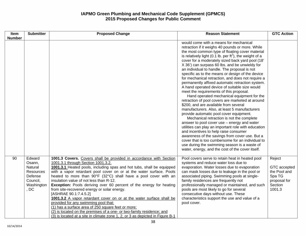
IAPMO Green Plumbing and Mechanical Code Supplement (GPMCS) 2015 Proposed Changes for Public Comment
38 10/14/2014
Item Number
Submitter Proposed Change Reason Statement GTC Action
would come with a means for mechanical retraction if it weighs 40 pounds or more. While the most common type of floating cover material is relatively light (0.1 lb. per ft2), the weight of a cover for a moderately sized back yard pool (18’ X 36’) can surpass 60 lbs. and be unwieldy for an individual to handle. The proposal is not specific as to the means or design of the device for mechanical retraction, and does not require a permanently affixed automatic retraction system. A hand operated device of suitable size would meet the requirements of this proposal. Hand operated mechanical equipment for the retraction of pool covers are marketed at around $200, and are available from several manufacturers. Also, at least 5 manufacturers provide automatic pool cover equipment. Mechanical retraction is not the complete answer to pool cover use – energy and water utilities can play an important role with education and incentives to help raise consumer awareness of the savings from cover use. But a cover that is too cumbersome for an individual to use during the swimming season is a waste of water, energy, and the cost of the cover itself.
90 Edward Osann, Natural Resources Defense Council, Washington, DC
1001.3 Covers. Covers shall be provided in accordance with Section 1001.3.1 through Section 1001.3.2. 1001.3.1 Heated pools, including spas and hot tubs, shall be equipped with a vapor retardant pool cover on or at the water surface. Pools heated to more than 90°F (32°C) shall have a pool cover with an insulation value of not less than R-12. Exception: Pools deriving over 60 percent of the energy for heating from site-recovered energy or solar energy. [ASHRAE 90.1:7.4.5.2] 1001.3.2 A vapor retardant cover on or at the water surface shall be provided for any swimming pool that: (1) has a surface area of 250 square feet or more; (2) is located on the premises of a one- or two-family residence; and (3) is located at a site in climate zone 1, 2, or 3 as depicted in Figure B-1
Pool covers serve to retain heat in heated pool systems and reduce water loss due to evaporation. Water losses due to evaporation can mask losses due to leakage in the pool or associated piping. Swimming pools at single-family residences are frequently not professionally managed or maintained, and such pools are most likely to go for several consecutive days without use. These characteristics support the use and value of a pool cover.
Reject GTC accepted the Pool and Spa TG proposal for Section 1001.3

IAPMO Green Plumbing and Mechanical Code Supplement (GPMCS) 2015 Proposed Changes for Public Comment
39 10/14/2014
Item Number
Submitter Proposed Change Reason Statement GTC Action
of Appendix B of ASHRAE Standard 90.1.
91 Plumbing Water Efficiency TG
Table 1101.1 Add the following standards to Table 1101.1: ICC A117.1 and CSA B651
Add standards as referenced in proposed revised Section 402.6.2
Accept as Submitted
92 Gary Soto Table 1101.1
STANDARD NUMBER-YEAR STANDARD TITLE REFERENCED
SECTIONIAPMO PS 59 -
2012 Wastewater
Diverter Valves and Diversion Systems
502.2.3
Added Standard from proposed revision for Section 502.2.3
Accept as Submitted
93 Composting Toilets Task Group
Composting Toilets and Urine Diversion Systems – SEE SEPARATE DOCUMENT
Water scarcity and pollution concerns are driving the adoption of composting and urine diversion toilet systems in the US and internationally. The composting provisions provide for strict protections on public health while also encouraging the growth of domestic industry and innovation in composting and urine diversion systems. In combination with performance testing, prescriptive guidelines for ventilation, screening, and retention time of compost and urine present simple, easy-to-follow and inspection requirements that protect public health even in the event of system failure and poor owner maintenance. These provisions mandate that unsaturated aerobic decomposition conditions be maintained, that temperature stay within the range of beneficial decomposing organisms, and that decomposition occur for at least one year, outside the survival time of pathogens. In the event of maintenance failure, watertightness, screening, and ventilation requirements prevent both public health threats from arising and major inconvenience in the home. Urine diversion can reduce nitrogen in domestic
Accept as Submitted

IAPMO Green Plumbing and Mechanical Code Supplement (GPMCS) 2015 Proposed Changes for Public Comment
40 10/14/2014
Item Number
Submitter Proposed Change Reason Statement GTC Action
wastewater by 80%, and Composting Toilet Systems can reduce household nitrogen by close to 90%, both at installed costs of $3-6000. This is a higher performance than Alternative Treatment Technologies (ATTs) and sand filters currently required in many jurisdictions with surface and groundwater concerns, and at a fraction of the cost. These provisions bring new, lower cost options for environmental protection to homeowners. Two pathways of compliance are paved for either listed systems to the NSF/ANSI Standard 41, or alternative systems meeting the prescriptive requirements contained in this section.
94 IAPMO Staff
ASHRAE 90.1-2013 Updates – SEE SEPARATE DOCUMENT Update GPMCS to 90.1-2013 Accept as Submitted