Code Building Plumbing Enforcement Mechanical Electrical ...

June 2019
OEDM- Spring 2019 Career Development1
Significant Changes to the CT Mechanical and Plumbing Codes
Spring 2019 Career Development Series
John Tye,
Office of the State Building Inspector DAS Office of Education and Data Management
Plumbing and Mechanical Code “Highlights and Significant Changes”
Part 1 - 2015 International Plumbing Code (IPC)
Part 2 - 2015 International Mechanical Code (IMC)
Part 3 - Significant changes to the 2015 NFPA 54 National Fuel Gas Code and Chapter 24 Fuel Gas located in the 2015 International Residential Code.
Part 1 - 2015 International Plumbing Code (IPC)
• The following slides pertain to significant changes to the IPC.
• Some of the following referenced code sections were added and many were modified. The additions and modifications are identified at the beginning of each code section.
• “New additions and modifications” are identified by being underlined in black.
• “Deleted code sections and associated language” are identified in red and are underlined in red.
June 2019
OEDM- Spring 2019 Career Development2
Chapter 2 “Definitions”
• The following definitions were either added or modified.
• Alternate Onsite Nonpotable Water Addition “Nonpotable water from other than public utilities, onsite surface sources, and subsurface natural freshwater sources. Examples of such water are graywater, on-site reclaimed water, collected rainwater, captured condensate, and rejected water from reverse osmosis systems.”
• Backflow Preventer Modification “A backflow prevention assembly, a backflow prevention device or other means or methods to prevent backflow into the potable water supply.”
Chapter 2 continued•Cleanout. “Connecticut change” An access opening in the
drainage system utilized for the removal of obstructions. Types of cleanouts include a removable plug or cap, and a removable fixture or fixture trap. Floor drains, floor sinks, mop sinks and roof drains are not acceptable cleanouts. Other definitions added by the Connecticut Supplement include, Building Official, Code Official, and Registered Design Professional. These definitions were also added in previous codes.
Chapter 2 continued
• Mechanical joint Modification “A connection between pipes, fittings, or pipes and fittings that is not screwed, caulked, threaded, soldered, solvent cemented, brazed, welded, or heat fused. A joint in which compression is applied along the centerline of the pieces being joined. In some applications, the joint is part of the coupling, fitting, or adapter.”
• Toilet Facility Addition “A room or space that contains not less than one water closet and one lavatory.”
• Waste Receptor Addition “A floor sink, standpipe, hub drain or a floor drain that receives the discharge of one or more indirect waste pipes.”
June 2019
OEDM- Spring 2019 Career Development3
Chapter 2 continued
• Drinking Fountain Modification “A plumbing fixture that is connected to the potable water distribution system and the drainage system. The fixture allows the user to obtain a drink directly from a stream of flowing water without the use of any accessories.”
• Water Dispenser Modification “A plumbing fixture that is manually controlled by the user for the purpose of dispensing potable drinking water into a receptacle such as a cup, glass or bottle. Such fixture is connected to the potable water distribution system of the premises. This definition also includes a freestanding apparatus for the same purpose that is not connected to the potable water distribution system and that is supplied with potable water from a container, bottle or reservoir.”
Chapter 2 continued• Water Cooler Modification “A drinking fountain that incorporates a
means of reducing the temperature of the water supplied to it from the potable water distribution system.”
• 410.4 Substitution “Where restaurants provide drinking water in a container free of charge, drinking fountains shall not be required in those restaurants. In other occupancies where drinking fountains are required, water coolers or bottled water dispensers shall be permitted to be substituted for not more than 50 percent of the required number of drinking fountains.”
• Fats, Oils and Greases (FOG) Disposal System Addition “A plumbing appurtenance that reduces nonpetroleum fats, oils, and greases in effluent by separation or mass and volume reduction.”
Chapter 3 “General Regulations”
• Section 305.4 Freezing. A water, soil or waste pipe shall not be installed outside of a building, or concealed in outside walls in any place subjected to freezing temperature, unless adequate provision is made to protect such pipe from freezing by insulation or heat or both. Water service pipe shall be installed not less than 48 inches deep. CT. Supplement Change.
• Table 308.5 Hanger Spacing Modification
• Footnote “b” Mid-story guide “For sizes 2 inches and smaller, a guide shall be installed midway between required vertical supports. Such guides shall prevent pipe movement in a direction perpendicular to the axis of the pipe.”

June 2019
OEDM- Spring 2019 Career Development4
Chapter 3 continued
• Section 314.2.4.1 Ductless mini-split system traps. Addition Ductless mini-split equipment that produces condensation shall be provided with an in-line check valve located in the drain line or a trap.• Section 314.2.5 Drain line maintenance. Addition
Condensate drain lines shall be configured to permit the clearing of blockages and performance of maintenance without requiring the drain line to be cut.
Chapter 4 “Fixtures, Faucets and Fixture Fittings”Section 403.1 Minimum Number of Fixtures. CT. Supplement AMD.“Plumbing fixtures shall be provided for the type of occupancy and in the minimum number as shown in Table 403.1 based upon the actual use of the building or space. Types of occupancies not shown in Table 403.1 shall be considered individually by the building official. The number of occupants shall be determined by the International Building Code. Occupancy classification shall be determined in accordance with the International Building Code.”
Exceptions:
1. The following minimum fixtures shall be provided in Group R-1 bed and breakfast establishments: Water closets-one per two guest rooms; bathtubs/showers- one per two guest rooms. Plumbing fixtures in Group R-1 bed and breakfast establishments shall be permitted to be accessed from hallways and corridors and to be shared by guests.
Chapter 4 continued
2. Child washing and diaper changing facilities shall be permitted in lieu of bathtubs or showers in Group I-4 child care occupancies.
• Section 403.1.2 Single-user toilet facility and bathing room fixtures. CT. change The plumbing fixtures located in single-user toilet facilities and bathing rooms, including family or assisted-use toilet and bathing rooms that are required by Section 1109.2.1 of the International Building Code, shall contribute towards the total number of required plumbing fixtures for a building or tenant space. Single user toilet facilities and bathing rooms, and family or assisted-use toilet and bathing rooms shall be identified for use by any person.
June 2019
OEDM- Spring 2019 Career Development5
Chapter 4 continued• Section 403.2 Separate facilities. CT. change. Where plumbing fixtures are
required, separate facilities shall be provided for each sex.
• Exceptions:
• 1. Separate facilities shall not be required for dwelling units and sleeping units.
• 2. Separate facilities shall not be required in structures or tenant spaces with a total occupant load, including both employees and customers, of 15 or fewer.
• 3. Separate facilities shall not be required in mercantile occupancies in which the maximum occupant load is 100 or fewer.
Chapter 4 continued
• 4. Separate facilities shall not be required in business occupancies in which the maximum occupant load is 25 or fewer.
• 5. Toilet rooms in Educational Group E Kindergarten and day care occupancies, and in Institutional Group I-4 child day care may be designated as unisex which are primarily for children’s use.
• 6. Single-user toilet facility and bathing room fixtures provided in accordance with 403.1.2.
Chapter 4 continued
Section 403.3 Required Public Toilet Facilities. Modification Exceptions:“2. Structures and tenant spaces intended for quick transactions, including takeout, pick up and drop off, having a public access area less than or equal to 300 sq ft.”
June 2019
OEDM- Spring 2019 Career Development6
Chapter 4 continued
• Section 403.4.1 Directional Signage Modification
• “ Directional signage indicating the route to the required public toilet facilities shall be posted in accordance with Section 3107 of the International Building Code. Such signage shall be located in a lobby, corridor, or aisle or similar space, such that it can be readily seen from the main at the entrance to the building or tenant space. facilities for customers, and visitors.”
Chapter 4 continued• Section 405.3.4 Water closet compartment. CT. change. Each water
closet utilized by the public or employees shall occupy a separate compartment with walls or partitions and a door enclosing the fixture to ensure privacy.
• Exceptions: 1 and 3 are same wording.
• 2. Toilet rooms located in Educational Group E Kindergarten and day care occupancies, and in Institutional Group I-4 child day care and containing two or more water closets shall be permitted to have one water closet without an enclosing compartment provided the toilet room is accessed through a door or other configuration to provide privacy.
• Section 405.3.5 Urinal partitions. CT. change. The code language is the same except for exception #2.
Chapter 4 continued
•Exception 2. Toilet rooms located in Educational Group E Kindergarten and day care occupancies, and in Institutional Group I-4 child day care and containing two or more urinals shall be permitted to have one urinal without partitions provided the toilet room is accessed through a door or other configuration to provide privacy.

June 2019
OEDM- Spring 2019 Career Development7
Chapter 4 continued
• Sections 406.1 and 409.2 Backflow Protection for Clothes Washing and Dishwashing Machines Modification
• Section 406.1 Water Connection “The water supply to an automatic clothes washer shall be protected against backflow by an air gap that is integral with installed integrally within the machine or with the installation of a backflow preventer shall be installed in accordance with Section 608. Air gaps shall comply with ASME A112.1.3 or A112.1.2.
• Section 409.2 Water Connection “The water supply to a dishwashing machine shall be protected against backflow by an air gap that is integral with the machine or a backflow preventer shall be installed in accordance with Section 608. Air gaps shall comply with ASME A112.1.3 or A112.1.2.”
Chapter 4 continued• Section 413.1 Food Waste Disposer Approval Modification
• Section 413.1 Approval. “Domestic food waste grinders disposers shall conform to ASSE 1008 and shall be listed and labeled in accordance with UL 430. Food waste grinders disposers shall not increase the drainage fixture unit load on the sanitary drainage system.”
• Section 417.4.1 Walls and Floors in Bathtub and Shower Areas Modification
• “ Bathtub floors, shower floors, the wall areas above built-in tubs withthat have installed shower heads and walls in shower compartments shall be constructed of smooth, noncorrosive corrosion-resistant and nonabsorbent waterproof materials. Wall materials shall extend to a height of not less than 6 feet above the room floor level, and not less than 70 inches above the drain of the tub or shower, where measured from the compartment floor at the drain. Such walls shall form a water-tight joint with each other and with either the tub, receptor or shower floor.”
Chapter 4 continued
• Section 420.1 Water Closet Approval Modification
• Section 420.1 Approval “Water closets equipped with a dual flushing device shall comply with ASME A112.19.14.”
• Section 421.1 Whirlpool Tub Approval Modification
• Section 421.1 Approval “Whirlpool bathtubs shall comply with ASME A112.19.7/CSA B45.10 and shall be listed and labeled in accordance with UL 1795.”
• 423.3 Footbaths, Pedicure Baths and Head Shampoo Sinks Addition
• Section 423.3 Footbaths, Pedicure Baths and Head Shampoo Sinks. “The water supplied to specialty plumbing fixtures such as pedicure chairs having an integral foot bath tub, footbaths and head shampoo sinks, shall be limited to a maximum temperatureof 120 degrees Fahrenheit. by a water temperature limiting device that conforms to ASSE 1070 or CSA.”
June 2019
OEDM- Spring 2019 Career Development8
Chapter 4 continued
•Section 424.8 Deck-Mounted Bath/Shower Transfer Valves Modification
•Section 424.8 Transfer Valves “Deck-mounted bath/shower transfer valves containing an integral atmospheric vacuum breaker shall conform to the requirements of ASME A112.18.7 ASME A112.18.1/CSA B125.1.”
Chapter 5 Water Heaters• Section 501.3 Water Heater Drain Valves Modification
• Section 501.3 Drain Valves “Drain valves for emptying shall be installed at the bottom of each tank-type water heater and hot water storage tank.” Drain valves shall conform to ASSE 1005. “The drain valve inlet shall not be less than ¾” nominal iron pipe size and the outlet shall be provided with male garden hose threads.”
• Section 504.6 Requirements for Discharge Piping Modification The discharge piping serving a pressure relief valve, temperature relief valve or combination thereof shall: (Items 1 thru 9 unchanged) “10. Not terminate not more than 6 inches above and not less than two times the discharge pipe diameter above the floor or waste receptor flood level rim.”
Chapter 5 continued•Section 504.7.2 Pan Drain Termination Modification “Where a pan drain was not previously installed, a pan drain shall not be required for a replacement water heater installation.”
•The drain pan is required! Don’t forget about the relief valve termination which must terminate in a safe location where damage will not occur.

June 2019
OEDM- Spring 2019 Career Development9
Chapter 6 Water Supply and Distribution
• Section 601.5 Rehabilitation of Piping Systems Addition “Where pressure piping systems are rehabilitated using an epoxy lining system, such lining system shall comply with ASTM F 2831.”
• Section 605.2.1 Lead Content of Drinking Water Pipe and Fittings. Addition “Pipe, pipe fittings, joints, valves, faucets, and fixture fittings utilized to supply water for drinking or cooking purposes shall comply with NSF 372 and shall have a weighted average lead content of 0.25 percent or less.”
• Section Tables 605.3 and 605.4, Section 605.16 CPVC/AL/CPVC Water Service and Water Distribution Piping Addition “A new type of CPVC
Chapter 6 continued• pipe has been added to Chapter 6.” Addition “Table 605.3 Water Service
Pipe and also added to Table 605.4 Water Distribution Pipe”
• In addition to the above tables the CPVC material has been added in a new Section 605.16.
• Tables 605.3, 702.2, 702.3, 702.4, 1102.4, and 1102.5 Asbestos Cement Pipe Modification “References to asbestos cement pipe and applicable referenced standards have been removed from the code.”
• Two standards for groove and shouldered mechanical joints and a press connect fitting standard have been added to the code. “Table 605.5, and Sections 605.14.3, 605.14.5, 605.18.3, 605.22.2, and 605.23.3.” Groove and Shouldered Mechanical Joints and Press- Connect Fittings
Chapter 6 continued
• Section 605.14.5 Press-connect Joints “Press-connect joints shall conform to one of the standards listed in Table 605.5. Press-connect joints shall be installed in accordance with the manufacturer’s instructions. Cut tube ends shall be reamed to the full inside diameter of the tube end. Joint surfaces shall be cleaned. The tube shall be fully inserted into the press-connect fitting. Press-connect joints shall be pressed with a tool certified by the manufacturer.”
• Section 605.18.3 Grooved and Shouldered Mechanical Joints “Grooved and shouldered mechanical joints shall comply with ASTM F 1476, shall be made with an approved elastomeric seal and shall be installed in accordance with the manufacturer’s instructions. Such joints shall be exposed or concealed.”

June 2019
OEDM- Spring 2019 Career Development10
Examples of press connect fittings.
Chapter 6 continued• Section 605.7, Table 605.7 Valve Compliance to Standards Modification
• “ Section 605.7 Valves. All valves shall be of an approved type and compatible with the type of piping material installed in the system. Ballvalves, gate valves, butterfly valves, globe valves and plug. Valves intended to supply drinking water shall meet the requirements of NSF 61. Valves shall conform to one of the standards listed in Table 605.7 or shall be approved.
• Section 607.2.1 Hot Water Temperature Maintenance System Controls. Modification “ Automatic For hot water distribution system circulating hotwater system pumps or and heat trace, the pumps and heat trace shall be arranged to be conveniently turned off either automatically or manually when there hot water system is not in operation. is limited not hot water demand. Ready access shall be provided to the operating controls.
Chapter 6 continued• This section and Section 607.2.1.1 shall not apply to hot water
temperature maintenance system controls in Group R2, R3, and R4 occupancies that are 3 stories or less in height above grade plane. Hot water temperature maintenance system controls in Group R2, R3, and R4 occupancies that are 3 stories or less in height above grade plane shall be in accordance with Section R403.4.1 of the International Energy Conservation Code.
• Section 607.2.1.1 Storage Tank Hot Water Circulation Systems.
• “ Circulating pumps intended to maintain storage tank water temperature shall have controls that will limit operation of the pump from heating cycle start up to not greater than 5 minutes after the end of the cycle. Ready access shall be provided to the operating controls.”

June 2019
OEDM- Spring 2019 Career Development11
Chapter 6 continued• Section 607.3 Thermal Expansion Control Modification “A means of
controlling increased pressure caused by thermal expansion shall be provided where required in accordance with Sections 607.3.1 and 607.3.2. Where a storage water heater is supplied with cold water that passes through a check valve, pressure reducing valve or backflow preventer, a thermal expansion tank shall be connected to the water heater cold water supply pipe at a point that is downstream of all check valves, pressure reducing valves, and backflow preventers. Thermal expansion tanks shall be sized in accordance with the tank manufacturer’s instructions and shall be sized such that the pressure in the water distribution system shall not exceed that required by Section 604.8.”
Example of thermal expansion tanks.
Chapter 6 continued• Sections 607.3.1 Pressure Reducing Valve and 607.3.2 Backflow Prevention
Device or Check Valve are deleted.
• Section 608.8.1 Signage Required Modification “ All nonpotable water outlets such as hose connections, open ended pipes, and faucets shall be identified at the point of use for each outlet with the words , “Nonpotable-not safe for drinking.” with signage that reads as follows: “Non-potable water is utilized for [application name]. Caution: Nonpotable water. DO NOT DRINK.” The words shall be legibly and indelibly printed on a tag or sign constructed of corrosion- resistant waterproof material or shall be indelibly printed on the fixture. The letters of the words shall not be less than 0.5 inches in height and in colors in contrast to the background on which they are applied. In addition to the required wordage, the pictograph shown in Figure 608.8.1 shall appear on the signage required by this section.”

June 2019
OEDM- Spring 2019 Career Development12
Chapter 6 continued
• Section 608.8.12 Information. Distribution Pipe Labeling and Marking Modification “Non-potable distribution piping shall be of the color purple and shall be embossed or integrally stamped or marked with the words: “CAUTION NO-POTABLE WATER – DO NOT DRINK” or shall be installed with a purple identification tape or wrap. Pipe identification shall include the contents of the piping system and an arrow indicating the direction of flow. Hazardous piping systems shall also contain information addressing the nature of the hazard. Pipe identification shall be repeated at intervals not exceeding 25 feet and at each point where the piping passes through a wall, floor or roof. Lettering shall be readily observable within the room or space where the piping is located.
Non- potable piping.
Chapter 6 continued
• Section 608.17 Protection of individual water supplies. CT. change.
•An individual water supply shall be located and constructed so as to be safeguarded against contamination in accordance with the Public Health Code of the State of Connecticut adopted pursuant to section 19a-36 of the Connecticut General Statutes.
June 2019
OEDM- Spring 2019 Career Development13
Chapter 7 Sanitary Drainage• Section 701.2 Sewer required. CT. change. Buildings in
which plumbing fixtures are installed and premises having drainage piping shall be connected to a public sewer, where required, or an approved private sewage disposal system in accordance with the Public Health Code adopted under authority of section 19a-36 of the Connecticut General Statutes.
Chapter 7 continued
• Section 702.5 Temperature Rating. Addition “ Where the wastewater temperature will be greater than 140 degrees F. the sanitary drainage piping material shall be rated for the highest temperature of the wastewater.”
• Section 803.1 Waste Water Temperature. The section was deleted.
• Section 703.6 Combined Sanitary and Storm Public Sewer. Addition
• “Where the public sewer is a combined system for both sanitary and storm water, the sanitary sewer shall be connected independently to the public sewer.”
Chapter 7 continued
• Section 705.11.2 Solvent Cementing. Modification The following exception was added.
• Exception: A primer is not required where both of the following conditions apply:
• 1. The solvent cement used is third-party certified as conforming to ASTM D 2564.
• 2. The solvent cement is used only for joining PVC drain, waste and vent pipe and fittings in non-pressure applications in sizes up to and including 4 inches in diameter.
• A code enforcement bulletin was issued by State Building Official Joe Cassidy with regard to the use of primer on the solvent cemented PVC joints.

June 2019
OEDM- Spring 2019 Career Development14
Chapter 7 continued
• Section 708.1.1 Horizontal drains and building drains. CT. change. Horizontal drainage pipes, including horizontal branch drains consisting of one or more fixtures, in buildings shall have cleanouts located at intervals of not more than 100 feet. Building drains shall have cleanouts located at intervals of not more than 100 feet except where manholes are used instead of cleanouts, the manholes shall be located at intervals of not more than 400 feet. The interval length shall be measured from the cleanout of manhole opening, along the developed length of the piping to the next drainage fitting providing access for cleaning, the end of the horizontal drain or the end of the building drain.
Chapter 7 continued
•Exception:
•Horizontal fixture drain piping serving a non-removable trap shall not be required to have a cleanout for the section of piping between the trap and the connection to a horizontal or vertical drain if located within four feet of developed length of such connection. The four feet shall be measured from the fixture trap weir to the connection at the horizontal or vertical piping.
Chapter 7 continued
• Section 708 Cleanouts for Drainage and Waste Systems Modification Section 708.1.3 Building Drain and Building Sewer Junction “The junction of the building drain and building sewer shall be served by a cleanout that is located at the junction or within 10 feet developed length of piping upstream of the junction. For the requirements of this section the removal of water closet shall not be required to provide cleanout access.”
• Section 708.1.6 Cleanout Plugs. “Cleanout plugs shall be brass, plastic or other approved materials. Cleanout plugs for borosilicate glass piping systems shall be of borosilicate glass. Brass cleanout plugs shall conform to ASTM A74 and shall be limited for use only on metallic piping systems. Plastic cleanout plugs shall conform to the referenced standards for plastic pipe fittings as indicated in Table 702.4. Cleanout plugs shall have a raised square head, countersunk square head or a countersunk slot head.

June 2019
OEDM- Spring 2019 Career Development15
Chapter 7 continued
• Where a cleanout plug will have a trim cover screw installed into the plug. The plug shall be manufactured with a blind end threaded hole for such purpose.
• Section 708.1.10 Cleanout Access. “ Required cleanouts shall not be installed in concealed locations. For the purposes of this section, concealed locations include , but are not limited to the inside of plenums, within walls, within floor/ceiling assemblies, below grade and in crawl spaces where the height from the crawl space floor to the nearest obstruction along the path from the crawl space opening to the cleanout location is less than 24 inches. Cleanouts with openings at a finished wall shall have the face of the opening located within 1 ½ inches of the finished wall surface. Cleanouts located below grade shall be extended to grade level so that the top of the cleanout plug is at or above grade. A cleanout installed in a floor or walkway that will not have a trim cover installed shall have a countersunk plug installed, so the top surface of the plug is flush with the finished surface of the floor or walkway.”
Chapter 7 continued
• Section 708.1.10.1 Cleanout Plug Trim Covers. “ Trim covers and access doors for cleanout plugs shall be designed for such purposes and shall be approved. Trim cover fasteners that thread into cleanout plugs shall be corrosion resistant. Cleanout plugs shall not be covered with mortar, plaster or any other permanent material.”
• Section 708.1.10.2 Floor Cleanout Assemblies. “ Where it is necessary to protect a cleanout plug from loads of vehicular traffic, cleanout assemblies in accordance with ASME A112.36.2M shall be installed.”
Chapter 7 continued• Section 708.3.4 Base of Stack. “The section has been
deleted.”• Section 715.1 Exception for Backwater Valve
Installations.• A new exception was added and reads as follows:
• Exception: “ In existing buildings, fixtures above the elevation of the manhole cover of the next upstream manhole in the public sewer shall not be prohibited from discharging through a backwater valve.”
• Section 716 Vacuum Drainage Systems Addition Section 716.1 Scope. Vacuum drainage systems shall be in accordance with Sections 716.2 through716.4.
• Section 716.2 System Design. Vacuum drainage systems shall be designed in accordance with the vacuum drainage system manufacturer’s instructions.

June 2019
OEDM- Spring 2019 Career Development16
Examples of backwater valves.
Chapter 7 continued• The system layout, including piping layout, tank assemblies, vacuum pump
assembly and other components necessary for proper function of the system, shall be in accordance with the manufacturer’s instructions. Plans, specifications and other data for such systems shall be submitted to the code official for review and approval prior to installation.”
• Section 717 Replacement of Sewers by Pipe-Bursting Method Addition Section 717.1 General. “This section shall govern the replacement of existing building sewer piping by pipe-bursting methods.”
• Section 717.2 Applicability. “The replacement of building sewer piping by pipe bursting methods shall be limited to gravity drainage piping of sizes 6 inches and smaller. The replacement piping shall be of the same nominal size as the existing piping.”
• Section 717.4 Pipe “The replacement piping shall be manufactured with an SDR of 17 and in compliance with ASTM F 714.”
Chapter 8 Indirect/Special Waste
• Sections 802.1, 802.1.1, and 802.1.8 Food Handling Equipment Indirect Connection Modification
• Section 802.1 Where Required. Food handling equipment in other than dwelling units, clearwater waste, dishwashing machines and utensil, pots, pans, and dish washing sinks shall discharge through an indirect waste pipe as specified in Sections 802.1.1 through 802.1.8. Healthcare related fixtures, devices and equipment shall discharge to the drainage system through an indirect waste pipe by means of an air gap in accordance with this chapter and Section 713.3. Fixtures not required by this section to be indirectly connected shall be directly connected to the plumbing system in accordance with Chapter7.

June 2019
OEDM- Spring 2019 Career Development17
Chapter 8 continued• Section 802.1.1 Food Handling. “ Equipment and
fixtures utilized for the storage, preparation and handling of food shall discharge through an indirect waste pipe by means of an air gap. Each well of a multi-compartment sink shall discharge independently to a waste receptor.”
• Section 802.1.8 Food Utensils, Dishes, Pots and Pans Sinks. “ Sinks in other than dwelling units, used for washing, rinsing, or sanitizing of utensils, dishes, pots, pans or service ware used in the preparation, serving or eating of food shall discharge indirectly through an air gap or air break to the drainage system.
• Section 802.3 Waste Receptors, Hub Drains and Standpipes. Modification Section 802.3 Waste Receptors. “Waste receptors shall be of an approved type. For other than hub drains that receive only clear-water waste and standpipes , a removable strainer or basket shall cover the waste outlet.
Chapter 8 continued• of waste receptors. Waste receptors shall not be installed in
ventilated concealed spaces, plenums, and crawl spaces, attics and interstitial spaces above ceilings and below floors. or in any inaccessible or unventilated space such as a closet or storeroom. Ready access shall be provided to waste receptors.”
• Section 802.3.2 Open Hub Drains Waste Receptors.
• “ A hub drain Waste receptors shall be permitted in the form of a hub or a pipe extending not less than 1 inch above a water-impervious floor. and are not required to have a strainer.
• Section 802.4 802.3.3 Standpipes. (No change to text)
Examples of non compliant piping.

June 2019
OEDM- Spring 2019 Career Development18
Example of an incorrectly connected 3 bay sink and correctly connected grease interceptor.
Examples of incorrect piping.
Chapter 9 Vents
•Section 903.1 Roof Extension. CT. change. “ Open vent pipes that extend through a roof shall be terminated not less than twelve inches above the roof, except where a roof is to be used for any purpose other than weather protection, the vent extensions shall terminate not less than 7 feet above the roof.”

June 2019
OEDM- Spring 2019 Career Development19
Chapter 10 Traps, Interceptors and Separators• Section 1002.1 Exception for Traps for Parking Garage Floor Drains
Modification Section 1002.1 Fixture traps.
• Exceptions 1 thru 3 (No change to text)
• Exception #4 “Floor drains in multilevel parking structures that discharge to a building storm sewer shall not be required to be individually trapped. Where floor drains in multilevel parking structures are required to discharge to a combined building sewer system, the floor drains shall not be required to be individually trapped provided that they connect to a main trap in accordance with Section 1103.1.”
• Sections 1002.4, 1002.4.1 Trap Seal Protection against Evaporation Modification Section 1002.4 Trap Seals. “ Each fixture trap shall have a liquid seal of not less than 2 inches and not more than 4 inches or deeper for
Chapter 10 continued• special designs relating to accessible fixtures. Where a trap seal is subject to
loss by evaporation a trap seal primer valve shall be installed. Trap seal primer valves shall connect to a trap at a point above the level of the trap seal. A trap seal primer valve shall conform to ASSE 1018 or ASSE 1044.
• Section 1002.4.1 Trap Seal Protection. “Trap seals of emergency floor drain traps and traps subject to evaporation shall be protected by one of the methods in Sections 1002.4.1.1 through 1002.4.1.4.”
• Section 1002.4.1.1 Potable Water Supplied Trap Seal Primer Valve. “ A potable water supplied trap seal primer valve shall supply water to the trap. Water supplied trap seal primer valves shall conform to ASSE 1018. The discharge pipe from the trap seal primer valve shall connect to the trap above the trap seal on the inlet side of the trap.
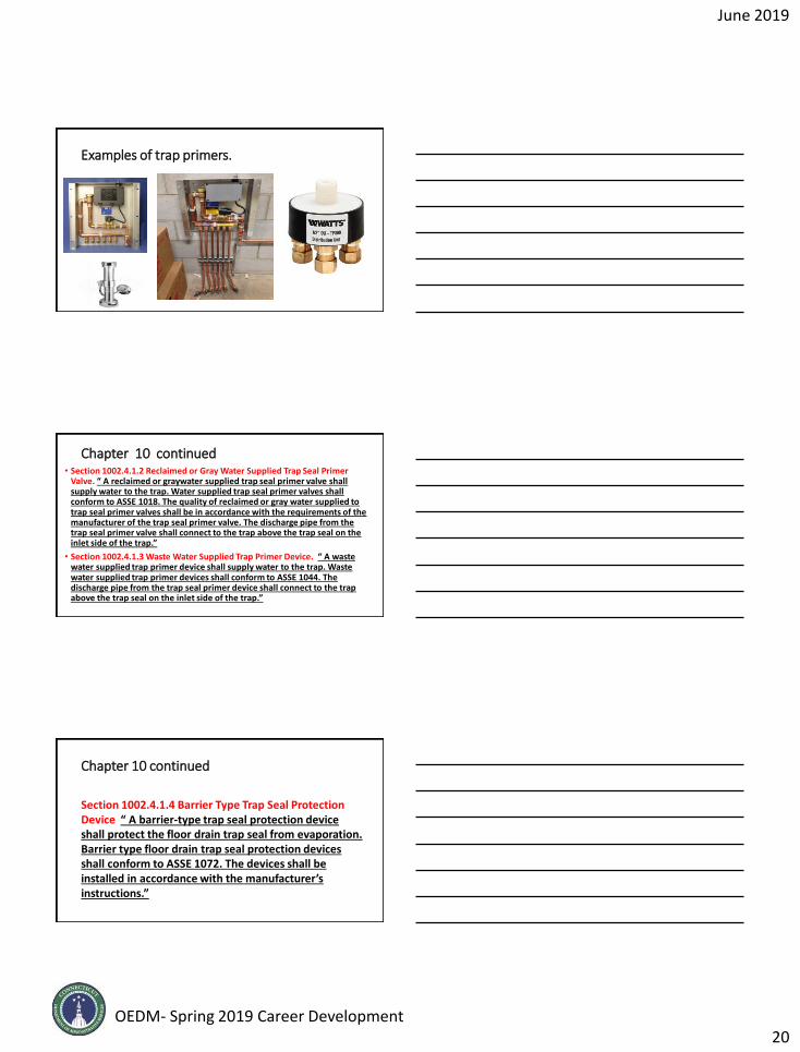
Examples of trap primers.
June 2019
OEDM- Spring 2019 Career Development20
Examples of trap primers.
Chapter 10 continued• Section 1002.4.1.2 Reclaimed or Gray Water Supplied Trap Seal Primer
Valve. “ A reclaimed or graywater supplied trap seal primer valve shall supply water to the trap. Water supplied trap seal primer valves shall conform to ASSE 1018. The quality of reclaimed or gray water supplied to trap seal primer valves shall be in accordance with the requirements of the manufacturer of the trap seal primer valve. The discharge pipe from the trap seal primer valve shall connect to the trap above the trap seal on the inlet side of the trap.”
• Section 1002.4.1.3 Waste Water Supplied Trap Primer Device. “ A waste water supplied trap primer device shall supply water to the trap. Waste water supplied trap primer devices shall conform to ASSE 1044. The discharge pipe from the trap seal primer device shall connect to the trap above the trap seal on the inlet side of the trap.”
Chapter 10 continued
Section 1002.4.1.4 Barrier Type Trap Seal Protection Device “ A barrier-type trap seal protection device shall protect the floor drain trap seal from evaporation. Barrier type floor drain trap seal protection devices shall conform to ASSE 1072. The devices shall be installed in accordance with the manufacturer’s instructions.”

June 2019
OEDM- Spring 2019 Career Development21
Chapter 10 continued• Section 1003.3 Grease Interceptors. CT. change. Grease
interceptors that serve plumbing systems connected to private, on-site septic systems shall comply with the requirements of Sections 1003.3.1 to 1003.3.5, inclusive and in accordance with the Public Health Code adopted pursuant to section 19a-36 of the Connecticut General Statutes. Grease interceptors that serve plumbing systems connected via a sanitary sewer to publicly owned treatment works shall comply with the Department of Energy and Environmental Protection’s General Permit for the Discharge of Wastewater Associated with Food Preparation Establishments.
Examples of trap seal devices.
Chapter 10 continued
• Section 1003.3.3.6 Gravity Grease Interceptors Addition Section 1003.3.6 Gravity Grease Interceptors and Gravity Interceptors with Fats, Oils and Greases Disposal Systems. “The required capacity of gravity grease interceptors and gravity grease interceptors with fats, oils and greases disposal systems shall be determined by multiplying the peak drain flow into the interceptor in gallons per minute by a retention time of 30 minutes. Gravity grease interceptors shall be designed and tested in accordance with IAPMO/ANSI Z100. Gravity grease interceptors with fats, oils and grease disposal systems shall be designed and tested in accordance with ASME 112.14.6 and IAPMO / ANSI Z 1001. Gravity grease interceptors and gravity grease interceptors fats, oils, and grease
June 2019
OEDM- Spring 2019 Career Development22
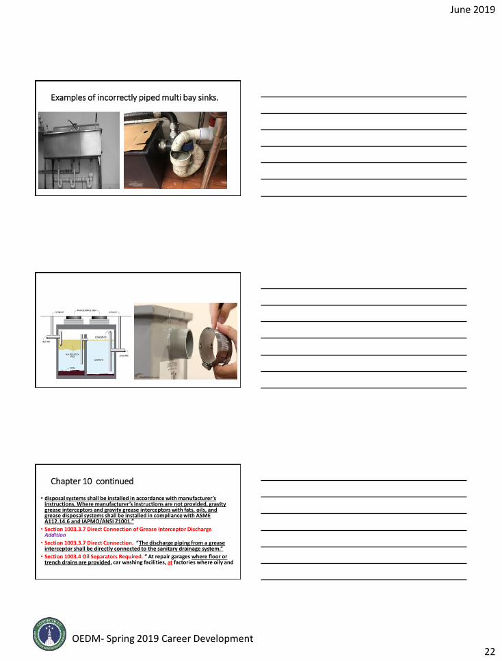
Examples of incorrectly piped multi bay sinks.
Chapter 10 continued
• disposal systems shall be installed in accordance with manufacturer’s instructions. Where manufacturer’s instructions are not provided, gravity grease interceptors and gravity grease interceptors with fats, oils, and grease disposal systems shall be installed in compliance with ASME A112.14.6 and IAPMO/ANSI Z1001.”
• Section 1003.3.7 Direct Connection of Grease Interceptor Discharge Addition
• Section 1003.3.7 Direct Connection. “The discharge piping from a grease interceptor shall be directly connected to the sanitary drainage system.”
• Section 1003.4 Oil Separators Required. “ At repair garages where floor or trench drains are provided, car washing facilities, at factories where oily and

June 2019
OEDM- Spring 2019 Career Development23
Examples of automatic grease recovery units.
Chapter 10 continued• And flammable liquid wastes are produced and in hydraulic elevator pits, oil
separators shall be installed into which all oil bearing, grease bearing or flammable wastes shall be discharged before emptying into the building drainage system or other point of disposal.
• Exception: “An oil separator is not required in hydraulic elevator pits where an approved alarm system is installed. Such alarm systems shall not terminate the operation of pumps utilized to maintain emergency operation of the elevator by firefighters.”
• Section 1003.6 Clothes Washer Discharge Interceptor. Modification
• Section 1003.6 Laundries Clothes Washer Discharge Interceptor. “Laundry facilities not installed within an individual dwelling unit or intended for individual family use Clothes washers shall discharge through an interceptor that is provided with a wire basket or similar device, removable for cleaning,
Chapter 10 continued• that prevents passage into the drainage system of solids ½ inch or larger in
size, string, rags, buttons, or other materials detrimental to the public sewage system.”
• Exceptions:
• 1. Clothes washers in individual dwelling units shall not be required to discharge through an interceptor.
• 2. A single clothes washer designed for use in individual dwelling units and installed in a location other than an individual dwelling unit shall not be required to discharge through an interceptor.
• Section 1003.9 Venting of Interceptors and Separators. Modification“Interceptors and separators shall be designed so as not to become air bound.

June 2019
OEDM- Spring 2019 Career Development24
Chapter 10 continued
•where tight covers are utilized. Each Interceptors or and separators shall be vented in accordance with one of the methods in Chapter 9. where subject to a loss of trap seal.”
Examples of commercial clothes washer interceptors.
June 2019
OEDM- Spring 2019 Career Development25
Chapter 11 Storm Drainage• Sections 1105.2 and 1106.2 Sizing of Roof Drains, Vertical and Horizontal
Storm Drain Piping. Modification
• Section 1105.2 Roof Drain Flow Rate. “ The published roof drain flow rate based upon the head of water above the roof drain shall be used to size the storm drainage system in accordance with Section 1106. The flow rate used for sizing the storm drainage piping shall be based on the maximum anticipated ponding at the roof drain.”
• Section 1106.2 Vertical Conductors and Leaders. Vertical conductors and leaders shall be sized for the maximum projected roof area, in accordance with Table 1106.2(1) and Table 1106.2(2). deleted
• Table 1106.2(1) Size of Circular Vertical Conductors and Leaders deleted
Chapter 11 continued
• Table 1106.2(2) Size of Rectangular Vertical Conductors and Leaders.Deleted
• Section 1106.3 Building Storm Drains and Sewers. “The size of the building storm drain, building storm sewer and their horizontal branches having a slope of one-half unit or less vertical in 12 units horizontal (4 percent slope) shall be based on the maximum projected roof area in accordance with Table 1106.3. The slope of horizontal branches shall not be less than one- eight unit vertical in 12 units horizontal (1 percent slope) unless otherwise approved. Deleted
• Table 1106.3 Size of Horizontal Storm Drainage Piping Deleted
• Section 1106.2 Size of Storm Drain Piping “Vertical and horizontal storm
Chapter 11 continued• drain piping shall be sized based on the flow rate through the roof drain.
The flow rate in storm drain piping shall not exceed that specified in Table 1106.2.
• Sections 1106.3 and 1106.6 Sizing of Gutters and Leaders Modification
• Section 1106.3 Vertical Leader Sizing. “ Vertical leaders shall be sized based on the flow rate from horizontal gutters or the maximum flow rate through roof drains. The flow rate through vertical leaders shall not exceed the values that are specified in Table 1106.3.”
• Section 1106.6 Size of Roof Gutters. “The size of semicircular gutters shall be based on the maximum projected roof area in accordance with Table 1106.6. Horizontal gutters shall be sized based on the flow rate from the roof surface. The flow rate in horizontal gutters shall not exceed the values that are specified in Table 1106.6.”
• Table 1106.6 Size of Semicircular Roof Gutters

June 2019
OEDM- Spring 2019 Career Development26
Chapter 12 Special Piping and Storage Systems
• Section 1201.1 Scope CT. change. The provisions of this chapter shall govern the design and installation of piping and storage systems for non-flammable medical gas systems and non-medical oxygen systems. All maintenance and operation of such systems shall be in accordance with the Connecticut State Fire Prevention Code.
Chapter 14 Subsurface Landscape Irrigation Systems
• Section 1401.1 General CT. change. Subsurface landscape irrigation systems shall comply with the Public Health Code adopted pursuant to section 19a-36 of the Connecticut General Statutes.
Part 2 - 2015 International Mechanical Code (IMC)
• The following slides pertain to significant changes to the IMC.
• Some of the following code sections were added and many were modified . The additions and modifications were identified at the beginning of each code section.
• New additions and modifications are identified by being underlined in black.
• Deleted code sections and associated language are identified in red and underlined in red.

June 2019
OEDM- Spring 2019 Career Development27
Chapter 2 Definitions• Air, Makeup. Any combination of outdoor and transfer air intended to
replace exhaust air and exfiltration.
• Air, Outdoor. Ambient air that enters a building through a ventilation system, through intentional openings for natural ventilation, or by infiltration.
• Air, Transfer Air moved from one indoor space to another.
• Conditioned Space. An area, room or space that is enclosed within the building thermal envelope and that is directly heated or cooled or that is indirectly heated or cooled. Spaces are indirectly heated or cooled where they communicate through openings with conditioned spaces, where they are separated from conditioned spaces by uninsulated walls, floors or ceilings, or where they contain uninsulated ducts, piping or other sources of heating or cooling.
Chapter 2 continued• Discrete Product. Products that are noncontinuous, individual, distinct
pieces such as, but not limited to, electrical, plumbing and mechanical products and duct straps, duct fittings, duct registers and pipe hangers.
• Exfiltration. Uncontrolled outward air leakage from conditioned spaces through unintentional openings in ceilings, floors and walls to unconditioned spaces or the outdoors caused by pressure differences across these openings resulting from wind, the stack effect created by temperature differences between indoors and outdoors, and imbalances between supply and exhaust airflow rates.
• Extra-Heavy-Duty Cooking Appliance. Extra-heavy-duty cooking appliances are those utilizing open flame combustion of solid fuel at any time.
• Flexible Air Connector. A conduit for transferring air between an air duct or plenum and an air terminal unit or between an air duct or plenum and an air inlet or air outlet. Such conduit is limited in its use, length and location.
Chapter 2 continued• Heavy-Duty Cooking Appliance. The wording is the same except smokers
and smoker ovens were added.
• Infiltration. Uncontrolled inward air leakage to conditioned spaces through unintentional openings in ceilings, floors and walls from unconditioned spaces or the outdoors caused by pressure differences across these openings resulting from wind, the stack effect created by temperature differences between indoors and outdoors, and imbalances between supply and exhaust airflow rates.
• Occupational Exposure Limit (OEL). The time weighted average (TWA) concentration for a normal eight-hour workday and a 40-hour workweek to which nearly all workers can be repeatedly exposed without adverse effect, based on the OSHA PEL, ACGIH TLV-TWA, AIHA WEEL, or consistent value.

June 2019
OEDM- Spring 2019 Career Development28
Chapter 3 General Regulations• Section 304.11 Fall-Arresting Restraint Systems Modification
• Section 304.11 Guards. “Guards shall be provided where various components appliances equipment fans or other components that require service and roof hatch openings are located within 10 feet of a roof edge or open side of a walking surface and such edge or open side is located more than 30 inches above the floor, roof, or grade below. The guard shall extend not less than 30 inches beyond each end of such appliances, equipment, fans, components that require service. and roof hatch openings and the Thetop of the guard shall be located not less than 42 inches above the elevated surface adjacent to the guard. The guard shall be constructed so as to prevent the passage of a 21 inch diameter sphere and shall comply with the loading requirements for guards specified in the International Building Code.
Chapter 3 continued• Exception: “Guards are not required where permanent fall arrest/ restraint
anchorage connector devices that comply with ANSI/ASSE Z359.1 are affixed for use during the entire roof covering lifetime. The devices shall be re-evaluated for possible replacement when the entire roof covering is replaced. The device4s shall be placed not more than 10 feet on center along hip and ridge lines and placed not less than 10 feet from the roof edge or open side of the wailing surface.”
• Section 306.1 Access “Appliances, controls devices, heat exchangers and HVAC system components that utilize energy shall be accessible for inspection, service, repair and replacement without disabling the function of a fire-resistance-rated assembly or removing permanent construction, other appliances, venting systems or any other piping or ducts not connected
Examples of fall arrest/restraint anchorage

June 2019
OEDM- Spring 2019 Career Development29
Chapter 3 continued
• to the appliance being inspected, serviced, repaired or replaced. A level working space at least 30 inches deep and 30 inches wide shall be provided in front of the control side to service an appliance.”
• Section 307.2.5 Condensate Drain Line Maintenance Addition Section 307.2.5 “Drain Line Maintenance. Condensate drain lines shall be configured to permit the clearing of blockages and performance of maintenance without requiring the drain line to be cut.”
Chapter 3 continued
• Section 307.2.4.1 Ductless mini-split system traps.
• Ductless mini-split equipment that produces condensate shall be provided with an in-line check valve located in the drain line, or trap.
Section 307.3 Condensate Pumps in Uninhabitable Spaces Addition Section 307.3 Condensate Pumps. “ Condensate pumps are often located in uninhabitable spaces, such as attics and crawl spaces, shall be connected to the appliance or equipment served such that when the pump fails, the appliance or equipment will be prevented from operating. Pumps shall be
installed in accordance with the manufacturer’s instructions.”
Example of cleanouts etc. to afford pipe cleaning. IMC Section 307.2.5.

June 2019
OEDM- Spring 2019 Career Development30
Examples of cooling coil piping.
Examples of venting of condensate piping.
Incorrectly installed condensate piping.

June 2019
OEDM- Spring 2019 Career Development31
Examples of condensate pumps with float switch in the event of pump failure.
Chapter 4 Ventilation• Sections 401.2, 407.1, Table 403.3.1.1 Ventilation Required Modification
• Section 401.2 Ventilation Required The following language was added to the section. “Ambulatory care facilities and Group I-2 occupancies shall be ventilated by mechanical means in accordance with Section 407.”
• Section 407.1 General. “ Mechanical ventilation for ambulatory care facilities and Group I-2 occupancies shall be designed and installed in accordance with this code and ASHRAE 170.”
• Table 403.3.1.1 Minimum Ventilation Rates “ The ventilation provisions of Section 403 of the 2012 IMC specific to health care facilities no longer apply and have been deleted from the table.” ASHRAE 170 is a ventilation standard for health care facilities, and it contains special provisions for the unique nature of such occupancies.”
Chapter 4 continued• Sections 403.2.1, Table 403.3.1.1 Recirculation of Air Clarification
• “ 403.2.1 Recirculation of Air” Language was modified in exceptions #3 and #4.
• Exception #3 “Where mechanical exhaust is required by note b in Table 403.3.1.1, recirculation of air from such spaces shall be prohibited. Recirculation of air that is contained completely within such spaces shall not be prohibited. Where recirculation of air is prohibited, all air supplied to such spaces shall be exhausted, including any air in excess of that required by Table 403.3.1.1.”
• Exception #4 “ Where mechanical exhaust is required by note g in Table 403.3.1.1, mechanical exhaust is required and recirculation from such spaces is prohibited where more than 10 percent of the resulting supply airstream consists of air recirculated from these spaces. Recirculation of air that is contained completely within such spaces shall not be prohibited.”

June 2019
OEDM- Spring 2019 Career Development32
Chapter 4 continued• Section 403.3 Outdoor Air and Local Exhaust Airflow Rates Addition
• Change Summary: “The new text introduces the basic requirements of ASHRAE 62.2 related to mechanical ventilation for Group R-2, R-3 and R-4 buildings three stories or less in height.”
• Section Table 403.3.1.1 Manicure and Pedicure Station Exhaust Rate Modification
• Change Summary: “The revised note h to Table 403.3.1.1 recognizes new Section 502.20 for the design of manicure and pedicure station exhaust systems and also specifies the applicability to both. Note h addresses the relationship between the source capture system exhaust-flow rate and the exhaust-flow rate specified within the table for nail salons.
Chapter 4 continued• Section 404.1 Intermittent Operation of Mechanical Ventilation Systems for
Enclosed Parking Garages Modification
• Section 404.1 Enclosed Parking Garages. “ Where mechanical ventilation systems for enclosed parking garages shall be permitted to operate intermittently, such operation shall be automatic in accordance with Item 1, Item 2 or both by means of carbon monoxide detectors applied in conjunction with nitrogen dioxide detectors. Such detectors shall be installed in accordance with their manufacturer’s recommendations.”
• 1. The system shall be arranged to operate automatically upon detection of vehicle operation or the presence of occupants by approved automatic detection devices.
• 2. The system shall be arranged to operate automatically by means of carbon monoxide detectors applied in conjunction with nitrogen dioxide detectors. Such detectors shall be installed in accordance with their manufacturer’s recommendations.
Chapter 5 Exhaust Systems• Section 501.3 Mechanical Exhaust System Discharge Modification
• Section 501.3 Exhaust Discharge “ The air removed by every mechanical exhaust system shall be discharged outdoors at a point where it will not cause a public nuisance and not less than the distances specified in Section 501.3.1. The air shall be discharged to a location from which it cannot again be readily drawn in by a ventilating system. Air shall not be exhausted into an attic, crawl space, or be directed onto walkways.”
• A new exception #3 was added.
• 3. Where installed in accordance with the manufacturer’s instructions and where mechanical or natural ventilation is otherwise provided in accordance with Chapter 4, listed and labeled domestic ductless range hoods shall not be required to discharge to the outdoors.

June 2019
OEDM- Spring 2019 Career Development33
Chapter 5 continued• Section 502.20 Manicure and Pedicure Station Exhaust System Addition
Section 502.20 Manicure and Pedicure Stations. “Manicure and pedicure stations shall be provided with an exhaust system in accordance with Table 403.3.1.1, note h. Manicure tables and pedicure stations not provided with factory-installed exhaust inlets shall be provided with exhaust inlets located not more than 12 inches horizontally and vertically from the point of chemical application.”
• Sections 504.5, and 504.8.4.3 Dryer Exhaust Duct Power Ventilators Addition
• Section 504.5 Dryer Exhaust Duct Power Ventilators. “Domestic dryer exhaust duct power ventilators shall be listed and labeled to UL 705 for use in dryer exhaust duct systems. The dryer exhaust duct power ventilator shall be installed in accordance with the manufacturer’s instructions.”
Chapter 5 continued• Section 504.8.4.3 Dryer Exhaust Duct Power Ventilator Length. “The
maximum length of the exhaust duct shall be determined by the dryer exhaust duct power ventilator manufacturer’s installation instructions.”
• Section 504.8.2 Dryer Exhaust Duct Installation Modification
• Section 504.6.2 504.8.2 Duct Installation. “Exhaust ducts shall be supported at 4 foot intervals and secured in place. The insert end of the duct shall extend into the adjoining duct or fitting in the direction of airflow. Ducts shall not be joined with screws or similar fasteners that protrude more than 1/8 th inch into the inside of the duct.”
• Sections 505.1 and 505.4 Domestic Range Hoods Modification
• Section 505.1 Domestic Systems. “ Where domestic range hoods and domestic appliances equipped with downdraft exhaust are located within dwelling units provided, such hoods and appliances shall discharge to the outdoors through
Chapter 5 continued• sheet metal ducts constructed of galvanized steel, stainless steel, aluminum
or copper. Such ducts shall have smooth inner walls, shall be air tight, shall be equipped with a backdraft damper, and shall be independent of all other exhaust systems.”
• The wording was changed in exception #1.
• Exceptions:
• 1. In other than Group I-1 and I-2, where installed in accordance with the manufacturer’s installation instructions and where mechanical or natural ventilation is otherwise provided in accordance with Chapter 4, listed and labeled ductless range hoods shall not be required to discharge to the outdoors.
• Section 505.4 Other than Group R. “In other than Group R occupancies, where domestic cooking appliances are utilized for domestic purposes

June 2019
OEDM- Spring 2019 Career Development34
Chapter 5 continued• such appliances shall be provided with domestic range hoods. Hoods and
exhaust systems shall be in accordance with Sections 505.1 and 505.2.”
• Section 505.3 Domestic Kitchen Exhaust Systems in Multistory Buildings Addition
• Section 505.3 Common Exhaust Systems for Domestic Kitchens Located in Multistory Structures. “ Where a common multistory duct system is designed and installed to convey exhaust from multiple domestic kitchen exhaust systems, the construction of the system shall be in accordance with all of the following:”
• 1. The shaft in which the duct is installed shall be constructed and fire resistance rated as required by the International Building Code.
• 2. Dampers shall be prohibited in the exhaust duct, except as specified
Chapter 5 continued• in Section 505.1. Penetrations of the shaft and ductwork shall be protected
in accordance with Section 607.5.5, exception 2.
• 3. Rigid metal ductwork shall be installed within the shaft to convey the exhaust. The ductwork shall be constructed of sheet steel having a minimum thickness of 0.0187 inch (No. 26 gage) and in accordance with SMACNA Duct Construction Standards.
• 4. The ductwork within the shaft shall be designed and installed without offsets.
• 5. The exhaust fan motor design shall be in accordance with Section 503.2.
• 6. The exhaust fan motor shall be located outside of the airstream.
• 7. The exhaust fan shall run continuously, and shall be connected to a standby power source.
Chapter 5 continued
• 8. Exhaust fan operation shall me monitored in an approved location and shall initiate an audible or visual signal when the fan is not in operation.
• 9. Where the exhaust rate for an individual kitchen exceeds 400 cfm makeup air shall be provided in accordance with Section 505.2.
• 10. A cleanout opening shall be located at the base of the shaft to provide access to the duct to allow for cleanout and inspection. The finished openings shall not be less than 12 inches by 12 inches.
• 11. Screens shall not be installed at the termination.
• 12. The common multistory duct system shall serve only kitchen exhaust and shall be independent of other exhaust systems.

June 2019
OEDM- Spring 2019 Career Development35
Chapter 5 continued• Section 506.3.7.1 Grease Duct Reservoirs Modification
• Section 506.3.7.1 Grease Duct Reservoirs. “ Grease duct reservoirs shall:
• The 2012 IMC contained seven requirements the 2015 IMC made the following modifications:
• 3. DELETED Have and length and width of not less than 12 inches. Where the grease duct is less than 12 inches in a dimension, the reservoir shall not be more than 2 inches smaller than the duct in that dimension.
• 3. NEW Extend across the full width of the duct and have a length of not lessthan 12 inches.
• 5. Have a bottom that is sloped to a point for drainage. slopes to a drain.
Chapter 5 continued• Section 506.3.8 Grease Duct Cleanouts and Openings Modification
• Section 506.3.8 The #2 requirement was modified.
• 2. “Sections of grease ducts that are inaccessible from the hood or discharge openings shall be provided with cleanout openings spaced not more than 20 feet apart and not more than 10 feet from changes in direction greater than 45 degrees.”
• Section 506.3.11 Grease Duct Enclosures Modification
• Section 506.3.11 Grease Duct Enclosures. “A commercial kitchen grease duct serving a Type 1 hood that penetrates a ceiling, wall, floor or any concealed space shall be enclosed from the point of penetration to the outlet terminal. In-line exhaust fans not located outdoors shall be enclosed as required for grease ducts. A duct shall penetrate exterior walls only at locations where
Chapter 5 continued• unprotected openings are permitted by the International Building Code. The
duct enclosure shall serve a single grease duct and shall not contain other ducts, piping or wiring systems. Duct enclosures shall be either a shaft enclosure in accordance with Section 506.3.11.1, a field-applied enclosure assembly in accordance with 506.3.11.2 or a factory-built enclosure assembly in accordance with Section 506.3.11.3. Duct enclosures shall have a fire-resistance rating of not less than that of the assembly penetrated and not less than 1 hour. Fire dampers and smoke dampers shall not be installed in grease ducts. Duct enclosures shall be as prescribed by Section 506.3.11.1, 506.3.11.2, or 506.3.11.3.”
• Section 506.3.11.4 Duct enclosure not required.
• Exception: A duct enclosure shall not be required for a grease duct that penetrates only a non-fire-resistance-rated roof/ceiling assembly.

June 2019
OEDM- Spring 2019 Career Development36
Chapter 5 continued• Section 506.5.1.2 In-Line Fan Location in Exhaust Ducts Serving Commercial
Kitchen Hoods Addition
• Section 506.5.1.2 In-Line Fan Location. “ Where enclosed duct systems are connected to in-line fans not located outdoors, the fan shall be located in a room or space having the same fire resistance rating as the duct enclosure. Access shall be provided for servicing and cleaning of fan components. Such rooms or spaces shall be ventilated in accordance with the fan manufacturer’s installation instructions.”
• Section 506.5.3 Hinged Up-Blast Fans for Type 1 Hoods Modification
• Section 506.5.3 Exhaust Fan Mounting. “ An Up-blast fans serving Type 1 hoods and installed in a vertical or horizontal position shall be hinged, andsupplied with a flexible weatherproof electrical cable to permit inspection and cleaning and shall be equipped with a means of restraint to limit the swing of the fan on its hinge. The ductwork shall extend a minimum of 18 inches above the roof surface.
Chapter 5 continued• Section 507.1 Type 1 Hood Installation Modification
• Section 507.1 General. “ Commercial kitchen exhaust hoods shall comply with the requirements of this section. Hoods shall be Type 1 or Type 2 and shall be designed to capture and confine cooking vapors and residues. A Type 1 or Type 2 hood shall be installed at or above all commercial cooking appliances in accordance with Sections 507.2 and 507.3. Where any cooking appliance under a single hood requires a Type 1 hood, a Type 1 hood shall be installed. Where a Type 2 hood is required, a Type 1 or 2 hood shall be installed. Where a Type 1 hood is installed, the installation of the entire system, including the hood, ducts, exhaust equipment and makeup air system shall comply with the requirements of Sections 506, 507, 508 and 509. Commercial kitchen exhaust hood systems shall operate during the cooking operation.
Chapter 5 continued• Section 507.1.1 Commercial Kitchen Exhaust Hood System Operation
• Modification Section 507.1.1 Operation. “ Commercial kitchen exhaust hood systems shall operate during the cooking operation. The hood exhaust rate shall comply with the listing of the hood or shall comply with Section507.5. Type 1 hood systems shall be designed and installed to automatically activate the exhaust fan whenever cooking operations occur. The activation of the exhaust fan shall occur through an interlock with the cooking appliances, by means of heat sensors or by means of other approved methods. The exhaust fan serving a Type 1 hood shall have automatic controls that will activate the fan when any appliance that requires such Type 1 hood is turned on, or a means of interlock shall be provided that will prevent operation of such appliances when the exhaust fan is not turned on. Where one or more temperature or radiant energy sensors are used to activate a Type 1 hood exhaust fan, the fan shall activate not more than 15-minutes after the first appliance,

June 2019
OEDM- Spring 2019 Career Development37
Chapter 5 continued• served by the hood, has been turned on. A method of interlock between an
exhaust hood system and appliances equipped with standing pilot burners shall not cause the pilot burners to be extinguished. A method of interlock between an exhaust hood system and cooking appliances shall not involve or depend upon any component of a fire extinguishing system.
• The net exhaust volumes for hoods shall be permitted to be reduced during part-load cooking conditions, where engineered or listed multi-speed or variable speed controls automatically operate the exhaust system to maintain capture and removal of cooking effluents as required by this section. Reduced volumes shall not be below that required to maintain capture and removal of effluents from the idle cooking appliances that are operating in a standby mode.”
Chapter 5 continued• Section 507.1.1.1 Heat Sensors for Multiple Commercial Kitchen Hoods
• Addition Section 507.1.1.1 Multiple Hoods Utilizing a Single Exhaust System
• “ Where heat or radiant energy sensors are utilized in hood systems consisting of multiple hoods served by a single exhaust system, such sensors shall be provided in each hood. Sensors shall be capable of being accessed from the hood outlet or from a cleanout location.”
• Section 507.2.8 Type 1 Hood Grease Filters Modification
• Section 507.11 507.2.8 Type 1 Grease Filters. “Type 1 hoods shall be equipped with grease filters listed and labeled in accordance with UL 1046 and designed for the specific purpose. Grease collecting equipment filters shall be provided with access for cleaning or replacement. The lowest edge of a grease filter located above the cooking surface shall be not less than the height specified in Table 507.11 507.2.8.
Chapter 5 continued• Section 507.11.1 507.2.8.1 Criteria. Filters shall be of such size,
type and arrangement as will permit the required quantity of air to pass through such units at rates not exceeding those for which the filter or unit was designed or approved. Filter units shall be installed in frames or holders so as to be readily removable without the use of separate tools, unless designed and installed to be cleaned in place and the system is equipped for such cleaning in place. Where filters are designed to be and required to be cleaned, removable filter units shall be of a size that will allow them to be cleaned in a dishwashing machine or pot sink. Filter units shall be arranged in place or provided with drip-intercepting devices to prevent grease or other condensate from dripping into food or on food preparation surfaces.

June 2019
OEDM- Spring 2019 Career Development38
Grease Filter Examples Listed and Labeled to “U.L. 1046”
Chapter 5 continued• Section 508.1.2 Air Balance for Commercial Kitchen Ventilation Systems
• Addition Section 508.1.2 Air Balance. “ Design plans for a facility with a commercial kitchen ventilation system shall include a schedule or diagram indicating the design outdoor air balance. The design outdoor air balance shall indicate all exhaust and replacement air for the facility, plus net exfiltration if applicable. The total replacement air airflow rate shall equal the total exhaust airflow rate plus the net exfiltration.”
• Section 510.4 and 510.5 Hazardous Exhaust Systems Modification
• Section 510.4 Independent System. “Hazardous exhaust systems shall be independent of other types of exhaust systems.”
• The remainder of the 510.4 Section has been deleted. Text in the previous editions of the code alluded to the recirculation of hazardous has been deleted. The previous exception was too broad in application, so the entire section has been formatted to clarify the scope of the exception.
Chapter 5 continued• Previous item 7 has been revised to prescribe the method for maintaining
continuous negative pressure.
• Section 510.5 Incompatible Materials and Common Shafts.
• “ Incompatible materials, as defined in the International Fire Code, shall not be exhausted through the same hazardous exhaust system. Hazardous exhaust systems shall not share common shafts with other duct systems, except where such systems are hazardous exhaust systems originating in the same fire area.”
• Exception: The provisions of this section shall not apply to laboratory exhaust systems where all of the following conditions apply:
• 1.All of the hazardous exhaust ductwork and other laboratory exhaust within both the occupied space and the shafts are under negative pressure while in operation.

June 2019
OEDM- Spring 2019 Career Development39
Chapter 5 continued• 2. The hazardous exhaust ductwork manifolded together within
the occupied space must originate within the same fire area.
• 3. Hazardous exhaust ductwork originating in different fire areas and manifolded together in a common shaft shall meet the provisions of Section 717.5.3, Exception 1.1 of the International Building Code.
• 4. Each control branch has a flow regulating device.
• 5. Perchloric acid hoods and connected exhaust shall be prohibited from manifolding.
• 6. Radioisotope hoods are equipped with filtration and/or carbon beds where required by the registered design professional.
• 7. Biological safety cabinets are filtered.
Chapter 5 continued
• 8. Each hazardous exhaust duct system shall be served by redundant exhaust fans that comply with either of the following:
• 8.1 The fans shall operate simultaneously in parallel and each fan shall be individually capable of providing the required exhaust rate.
• 8.2 Each of the redundant fans is controlled so as to operate when the other fan has failed or is shut down for servicing.
• Section 510.7.1.1 Hazardous Exhaust Duct Penetrations of Shafts Addition
• Section 510.7.1.1 “Hazardous exhaust ducts that penetrate fire-resistance-rated shafts shall comply with Section 714.3.1 or 714.3.1.2 of the International Building Code.
Chapter 5 continued
• Section 514.2 Energy Recovery Ventilation Systems Modification
• Section 514.2 Prohibited Applications. The sectionadded a new exception.
•Exception: “The application of ERV equipment that recovers sensible heat only utilizing coil-type heat exchangers shall not be limited to this section.”

June 2019
OEDM- Spring 2019 Career Development40
Chapter 6 Duct Systems• Section 601.5 Return Air Openings Addition
• Section 601.5 Return Air Openings. “ Return air openings for HVAC systemsshall comply with all of the following:”
• 1. Openings shall not be located less than 10 feet measured in any direction frpom an open combustion chamber or draft hood of another appliance located in the same room or space.
• 2. Return air shall not be taken from a hazardous or insanitary location or a refrigeration room as defined in this code.
• 3. The amount of return air taken from any room or space shall be not greater than the flow rate of supply air delivered to such room or space.
• 4. Return and transfer openings shall be sized in accordance with the appliance or equipment manufacturer’s installation instructions, ACCA Manual D or the design of the registered design professional.
Chapter 6 continued• 5. Return air taken from one dwelling unit shall not be discharged into
another dwelling unit.
• 6. Taking return air from a crawl space shall not be accomplished through a direct connection to the return side of a forced air furnace. Transfer openings in the crawl space enclosure shall not be prohibited.
• 7. Return air shall not be taken from a closet, bathroom, toilet room, kitchen, garage, boiler room, furnace room or unconditioned attic.
• Exceptions:
• 1. Taking return air from a kitchen is not prohibited where such return openings serve the kitchen and are located not less than 10 feet from the cooking appliances.
• 2. Dedicated forced air systems serving only the garage shall not be prohibited from obtaining return air from the garage.
Chapter 6 continued•“Section 918.6, including exceptions has been deleted from the code.”
• Section 602.1 Plenums Limited to One Fire Area Clarification
• Section 602.1 General. “Supply, return, exhaust, relief and ventilation ate plenums shall be limited to uninhabited crawl spaces, areas above a ceiling or below a floor, attic spaces and mechanical equipment rooms. Plenums shall be limited to one fire area. Air systems shall be ducted from the boundary of the fire area served directly to the air handling equipment. Fuel-fired appliances shall not be installed within a plenum.
• Section 602.2 Plenum Construction Modification
• Section 602.2 Construction. “Plenum enclosures shall be constructed of materials permitted for the type of construction classification of the building. Plenum enclosure construction materials that are exposed to the airflow

June 2019
OEDM- Spring 2019 Career Development41
Chapter 6 continued
• shall comply with the requirements of Section 703.5 of the International Building Code or such materials shall have a flame spread index of not more than 25 and a smoke-developed index of not more than 50 when tested in accordance with ASTM E84 or UL 723.”
• The use of gypsum boards to form plenums shall be limited to systems where the air temperatures do not exceed 125 degrees F and the building and mechanical system design conditions are such that the gypsum board surface temperature will be maintained above the airstream dew-point temperature. Air plenums formed by gypsum boards shall not be incorporated in air-handling systems utilizing evaporative coolers.
• Section 602.2.1.5 Discrete Plumbing and Mechanical Products in Plenums
• Addition 602.2.1.5 Discrete Plumbing and Mechanical Products in Plenums
Chapter 6 continued• Where discrete plumbing and mechanical products and appurtenances are
located in a plenum and have exposed combustible material, they shall be listed and labeled for such use in accordance with UL 2043.
• Section 202 General Definitions
• Discrete Product. Products that are non-continuous, individual, distinct pieces such as, but not limited to, electrical, plumbing, and mechanical products and duct straps, duct fittings, duct registers and pipe hangers.
• Section Table 603.4 Duct Construction Minimum Sheet Metal Thickness for Single Dwelling Units Modification Explanation: The table for duct gages for dwelling units has been replaced with thicknesses consistent with SMACNA sheet metal construction standard.
• Table 603.4 Duct Construction Minimum Sheet Metal Thickness for Single Dwelling Units foot note a
Chapter 6 continued• Section 603.9 Duct Joints, Seams and Connections Modification
• Section 603.9 Joints, Seams and Connections. “All longitudinal and transverse joints, seams and connections in metallic and nonmetallic ducts shall be constructed as specified in SMACNA HVAC DUCT CONSTRUCTION STANDARDS-METAL and FLEXIBLE and NAIMA FIBROUS GLASS DUCT CONSTRUCTION STANDARDS. All joints, longitudinal and transverse seams and connections in ductwork shall be securely fastened and sealed with welds, gaskets, mastics (adhesives), mastic-plus-embedded-fabric systems, liquid sealants or tapes. Closure sytems Tapes and mastics used to seal fibrous glass ductwork shall be listed and labeled in accordance with UL 181A and shall be marked “181 A-P” for pressure sensitive tape, “181 A-M” for mastic or “181 A-H” for heat sensitive tape. Closure systems Tapes and mastics used to seal metallic and flexible air ducts and flexible air connectors shall comply with UL 181 B and shall be marked “181 B-FX” for pressure sensitive tape or “181 B-M” for mastic. Duct connections to flanges of air distribution systems equipment shall be
June 2019
OEDM- Spring 2019 Career Development42
Chapter 6 continued
• sealed and mechanically fastened. Mechanical fasteners for use with flexible nonmetallic air ducts shall comply with UL 181B and shall be marked “181 B-C”. Closure systems used to seal metal all ductwork shall be installed in accordance with the manufacturer’s installation instructions. Unlisted duct tape is not permitted as a sealant on any duct.
• Exception: Continuously welded and locking-type longitudinal joints and seams in ducts operating at static pressures less than 2 inches of water column pressure classification shall not require additional closure systems.For ducts having a static pressure classification of less than 2 inches of water column additional closure systems shall not be required for continuously welded joints and seams and locking-type joints and seams of other than the snap-lock and button-lock types.
Chapter 7 Combustion Air
• Section 701.2 Dampered Openings Addition
• Section 701.2 Dampered Openings. “ Where combustion air openings are provided with volume, smoke or fire dampers, the dampers shall be interlocked with the firing cycle of the appliances served, so as to prevent operation of any appliance that draws combustion air from the room or space when any of the dampers are closed. Manual dampers shall not be installed in combustion air ducts. Ducts not provided with dampers and that pass through rated construction shall be enclosed in a shaft in accordance with the International Building Code. “
Chapter 8 Chimneys and Vents
• Section 802.9 Door Clearance to Vent Terminals Addition
• Section 802.9 Door Swing “ Appliance and equipment vent terminals shall be located such that doors cannot swing within 12 inches horizontally of the vent terminal. Door stops or closers shall not be installed to obtain this clearance.”

June 2019
OEDM- Spring 2019 Career Development43
Chapter 9 Specific Appliances, Fireplaces and Solid Fuel Burning Equipment
• Section 903.4 Gasketed Fireplace Doors Addition
• Section 903.4 Gasketed Fireplace Doors. “ A gasketedfireplace door shall not be installed on a factory-built fireplace except where the fireplace system has been specifically tested, listed and labeled for such use in accordance with UL 127.
Chapter 11 Refrigeration• Section 1102.3 Refrigerant Access Port Protection
Addition
• Section 1102.3 Access Port Protection. “ Refrigerant access ports shall be protected in accordance with Section 1101.10 whenever refrigerant is added to or recovered from refrigeration or air conditioning systems.”

June 2019
OEDM- Spring 2019 Career Development44
Part 3 “Significant changes to the2015 NFPA 54 National Fuel Gas Code and Chapter 24 Fuel Gas located in the 2015 International Residential Code.”
• “The following program contains changes to the NFPA 54 and IRC documents. Not all changes are included in this presentation. In addition to changes review of some of the former pertinent changes will be provided to attempt to address common questions submitted to our office.”
2018 Connecticut State Building Code
PERMITS“Permits for natural gas and propane gas installations shall
be taken out with the local Building Department.”
B/O
Significant changes to Chapter 24 Fuel Gas 2015 International Residential Code
•G2404.11 Condensate Pumps. “Condensate pumps located in uninhabitable spaces must be connected to the appliance to shut down the equipment in the event of pump failure.”

June 2019
OEDM- Spring 2019 Career Development45
2015 (IRC) Chapter 24 changes
• G2411.1.1 Electrical Bonding of Corrugated Stainless Steel Tubing. “The maximum allowable length of the bonding jumper for corrugated stainless steel tubing (CSST) is 75 feet. Bonding methods must comply with NFPA 70 and devices, such as clamps, must be listed in accordance with UL 467.”
2015 (IRC) Chapter 24 changes. *• Section G2411.1.1 CSST. Corrugated stainless steel tubing (CSST) gas
piping systems and piping systems containing one or more segments of CSST shall be bonded to the electrical service grounding electrode system or, where provided, the lightning protection electrode system.
• Section G2411.1.1.2 Size and material of jumper. The bonding jumper shall not be smaller than 6 AWG copper wire of equivalent.
• Section G2411.1.1.3 Bonding jumper length. The length of the bonding jumper between the connection to a gas piping system and the connection to a grounding electrode system shall not exceed 75 feet. Any additional grounding electrodes used shall be bonded to the electrical service grounding electrode system or, where provided, the lightning protection grounding electrode system.
Summary of CSST Bonding Requirements for newly adopted 2018 State Building Code.• Chapter 24 of the International Residential Code (IRC) and the
manufacturer’s instructions govern the installation of Corrugated Stainless Steel Tubing (CSST) for one and two family dwellings and townhouses. The 2018 Connecticut Supplement changed the code to the following.
• (Add) Section G2411.2(310.1) CSST. This section applies to corrugated stainless steel tubing (CSST) that is “not listed “ with an arch-resistant jacket or coating system in accordance with ANSI LC 1/CSA 6.26. CSST gas piping systems and piping systems containing one or more segments of CSST shall be electrically continuous and bonded to the electrical service grounding electrode system or, where provided, the lightning protection grounding electrode system.

June 2019
OEDM- Spring 2019 Career Development46
Summary continued• If the CSST is required to be bonded the following sections must be
satisfied and were added in the CT. Supplement.
• G2411.2.1 (310.1.1.1) Point of connection.
• G2411.2.2 (310.1.1.2) Size and material of jumper.
• G2411.2.3 (310.1.1.3) Bonding jumper length.
• G2411.2.4 (310.1.1.4) Bonding connections.
• G2411.2.5 (310.1.1.5) Connection devices.
• (Add) Section G2411.3 Arc-resistant CSST. This section applies to corrugated stainless steel tubing (CSST) that is listed with an arc-resistant jacket or coating system in accordance with ANSI LC 1/CSA 6.26. The CSST shall be electrically continuous and bonded to an
Summary continued• effective ground fault current path. Where any CSST component of a
piping system does not have an arc-resistant jacket or coating system, the bonding requirements of Section G2411.2 shall apply. Arc-resistant-jacketed CSST shall be considered to be bonded where it is connected to an appliance that is connected to an appliance grounding conductor of the circuit that supplies that appliance.
• Commercial installations (normally three family and greater) are governed by the National Fuel Gas Code NFPA 54 and the manufacturer’s installation instructions. The State of Connecticut has adopted the 2015 edition which still requires “ALL CSST MUST BE BONDED”, even with the arc-resistant jacket. 2015 NFPA 54 Section 7.13.2 CSST, requires all CSST to be bonded with no exception for the arc-resistant jacket.
Summary continued• The 2018 NFPA 54 contains a new Section 7.12.3, Arc-
Resistant Jacketed CSST which is considered to be bonded when it is connected to appliances that are connected to the appliance grounding conductor of the circuit supplying that appliance. A modification to use the new code for arc-resistant jacketed CSST and its bonding requirements would have to be submitted to the State Fire Marshal’s Office.
• Please be advised that CSST which has no arc-resistant jacket or coating system must be bonded, no exception.

June 2019
OEDM- Spring 2019 Career Development47
2015 (IRC) Chapter 24 changes. *
•Section G2411.1.1.4 Bonding connections. •Bonding connections shall be in accordance with
NFPA 70.
•Section G2411.1.1.5 Connection devices.•Devices used for making the bonding connections
shall be listed for the application in accordance with UL 467.
2015 (IRC) Chapter 24 changes *
•G2413.2 Maximum Gas Demand “Table G2413.2” and the reference to it were deleted to clarify that the code requires the actual maximum input rating of the appliances to be known and used for gas pipe sizing purposes.
•The volumetric flow rate of gas to be provided shall be adjusted for altitude where the installation is above 2,000 feet in elevation.
2015 (IRC) Chapter 24 changes
“G2414.6 Plastic Pipe, Tubing and Fittings” “PVC and CPVC pipe are expressly prohibited materials for supplying fuel gas.”

June 2019
OEDM- Spring 2019 Career Development48
2015 (IRC) Chapter 24 changes•G2414.10.4 Metallic fittings. A fifth reference has
been added with subsections: •5. Where pipe fittings are drilled and tapped in the
field, the operation shall be in accordance with all of the following:•5.1 The operation shall be performed on systems
having operating pressures of 5psi or less.•5.2 The operation shall be performed by the gas
supplier or the gas suppliers designated representative.
2015 (IRC) Chapter 24 changes
•5.3 The drilling and tapping operation shall be performed in accordance with written procedures prepared by the gas supplier.
•5.4 The fittings shall be located outdoors.
•5.5 The tapped fitting assembly shall be inspected and proven to be free of leakage.
Changes continued
•G2415.5 Fittings in Concealed Locations. “This section retains the basic intent while being completely reorganized to clarify the correct application. Threaded elbows, tees and couplings are now specifically approved for concealed locations as the code always intended. The code now provides the applicable referenced standards for fittings that are listed for concealed locations.”

June 2019
OEDM- Spring 2019 Career Development49
Changes continued•G2415.7 Protection of Concealed Piping Against Physical Damage. “The section on protection of piping has been completely rewritten to address more than just bored holes and notches in structural members. It now addresses piping parallel to framing members and piping within framing members. The new text requires that the protection extend well beyond the edge of members that are bored or notched.”
•G2415.8 Pipe cleaning. “The use of a flammable or combustible gas to clean or remove debris from a piping system shall be prohibited.”
Changes continued
•G2417.1.4 Section testing. The section has been reworded.
• A piping system shall be permitted to be tested as a complete unit or in sections. Under no circumstances shall a valve in a line be used as a bulkhead between gas in one section of the piping system and test medium in an adjacent section, except where a double block and bleed valve system is installed. A valve shall not be subjected to the test pressure unless it can be determined that the valve, including the valve closing mechanism, is designed to safely withstand the test pressure.
Changes continued
•G2421.2 Medium-Pressure Regulators “Medium-Pressure (MP) line regulators installed in ridged piping must have a union installed to allow removal of the regulator.”
•G2422.1 Connecting Portable and Movable Appliances “Where portable gas appliances are used outdoors, such as gas grills, fire pits, and patio heaters, the options for connecting to the gas distribution system are practically limited to gas hoses designed for the purpose. Such hoses must comply with ANSI Z21.54.”

June 2019
OEDM- Spring 2019 Career Development50
Changes continued
•G2426.7.1 Door Clearance to Vent Terminals “An appliance vent terminal is not permitted in a location within 12” of the arc of a swinging door.”•G2427.4.1, G2427.6.8.3 Plastic Piping for Appliance Vents
“The approval of plastic pipe for venting appliances is no longer the responsibility of the building official and, instead, that responsibility rests with the appliance manufacturer and the appliance listing agency. The code previously addressed only vents, which are defined as listed and labeled factory-made products. The code is no longer silent on the sizing of plastic pipe vents that do not fall under the definition of “vent.”
Changes continued•G2427.8 Venting System Termination Location “New text
addresses the location of sidewall vent terminals with respect to adjoining buildings. A 10 foot separation is required when a vent discharges in the direction of an opening in an adjacent building.” •G2439.4, G2439.7 Clothes Dryer Exhaust Ducts “New text
recognizes the use of dryer exhaust duct power ventilators (DEDPVs) to increase the allowable exhaust duct length for clothes dryers. A permanent label identifying the concealed length of the dryer exhaust is no longer required where the equivalent duct length does not exceed 35 feet.
Changes continued• For dryer exhaust duct exceeding 35 feet, a label or tag is
required whether the duct is concealed or not. Instead of prohibiting all duct fasteners such as screws and rivets, the code now limits the penetration of fasteners, where installed.
•G2439.6 Protection required. Protective shield plates.
•G2439.7 Domestic clothes dryer exhaust ducts. Exhaust ducts for domestic clothes dryers shall conform to the requirements of Sections G2439.7.1 through G2439.7.6.

June 2019
OEDM- Spring 2019 Career Development51
Changes continued
•G2447.2 Prohibited Location of Commercial Cooking Appliances.
“The code does not prohibit the installation of cooking appliances that are listed as both commercial and domestic appliances.” Appliances listed only as commercial cooking appliances are prohibited from being installed in a residence.
CSST “TracPipe, Counterstrike” by Omega Flex
•Review of the installation manual.
•Common questions concerning installation.
•In addition to this manual the installation must be in accordance with the most current edition of NFPA 54. (referenced in manual)
2015 National Fuel Gas Code *Chapter 1 Administrative
Chapter 2 Referenced Standards
Chapter 3 Definitions
Chapter 4 General
Chapter 5 Gas Piping System Design, Materials, and Components
Chapter 6 Pipe Sizing
Chapter 7 Gas Piping Installation
Chapter 8 Inspection, Testing, and Purging
Chapter 9 Appliance, Equipment, and Accessory Installation
Chapter 10 Installation of Specific Appliances
Chapter 11 Procedures to Be Followed to Place Appliance in Operation
Chapter 12 Venting of Appliances
Chapter 13 Sizing of Category I Venting Systems

June 2019
OEDM- Spring 2019 Career Development52
2015 National Fuel Gas Code *• 1.1 Scope
• 1.1.1 Applicability
• 1.1.1.1 This code is a safety code that shall apply to the installation of fuel gas piping systems, appliances, equipment, and related accessories as shown in 1.1.1.1 (A) through 1.1.1.1 (D).
• (A) Coverage of piping systems shall extend from the point of delivery to the appliance connections. For other than undiluted liquefied petroleum gas systems, the point of delivery shall be the outlet of the service meter assembly or the outlet of the service regulator or service shutoff valve where no meter is provided. For undiluted liquefied petroleum gas systems, the point of delivery shall be considered to be the outlet of the final pressure regulator, exclusive of line gas regulators, where no meter is installed. Where a meter is installed, the point of delivery shall be the outlet of the meter.
• (B) The maximum operating pressure shall be 125 psi (862 kPa).
Applicability continued *
• (C) Requirements for piping systems shall include design, materials, components, fabrication, assembly, installation, testing, inspection, operation, and maintenance.• (D) Requirements for appliances, equipment, and related
accessories shall include installation, combustion, and ventilation air and venting.

June 2019
OEDM- Spring 2019 Career Development53
2015 National Fuel Gas CodeShall Not Apply To
1.1.1.2 This code shall not apply to the following items (reference standards for some of which appear in Annex L):
• (1) Portable LP-Gas appliances and equipment of all types that are not connected to a fixed fuel piping system
• (2) Installation of appliances such as brooders, dehydrators, dryers, and irrigation equipment used for agricultural purposes
• (3) Raw material (feedstock) applications except for piping to special atmosphere generators
• (4) Oxygen–fuel gas cutting and welding systems
• (5) Industrial gas applications using such gases as acetylene and acetylenic compounds, hydrogen, ammonia, carbon monoxide, oxygen, and nitrogen
• (6) Petroleum refineries, pipeline compressor or pumping stations, loading terminals, compounding plants, refinery tank farms, and natural gas processing plants
• (7) Large integrated chemical plants or portions of such plants where flammable or combustible liquids or gases are produced by chemical reactions or used in chemical reactions
• (8) LP-Gas installations at utility gas plants
• (9) Liquefied natural gas (LNG) installations
• (10) Fuel gas piping in electric utility power plants
• (11) Proprietary items of equipment, apparatus, or instruments such as gas generating sets, compressors, and calorimeters
• (12) LP-Gas equipment for vaporization, gas mixing, and gas manufacturing
• (13) LP-Gas piping for buildings under construction or renovations that is not to become part of the permanent building piping system—that is, temporary fixed piping for building heat
• (14) Installation of LP-Gas systems for railroad switch heating
• (15) Installation of LP-Gas and compressed natural gas (CNG) systems on vehicles
• (16) Gas piping, meters, gas pressure regulators, and other appurtenances used by the serving gas supplier in distribution of gas, other than undiluted LP-Gas
• (17) Building design and construction, except as specified herein
• (18) Fuel gas systems on recreational vehicles manufactured in
• accordance with NFPA1192, Standard on Recreational Vehicles
• (19) Fuel gas systems using hydrogen as a fuel

June 2019
OEDM- Spring 2019 Career Development54
2015 National Fuel Gas Code *
•1.3 Retroactivity. Unless otherwise stated, the provisions of this code shall not be applied retroactively to existing systems that were in compliance with the provisions of the code in effect at the time of installation.
2015 National Fuel Gas Code *
1.4 Equivalency.The provisions of this code are not intended to prevent theuse of any material, method of construction, or installationprocedure not specifically prescribed by this code, providedany such alternative is acceptable to the authority havingjurisdiction. The authority having jurisdiction shall requirethat sufficient evidence be submitted to substantiate anyclaims made regarding the safety of such alternatives.
2015 National Fuel Gas Code Chapter 3 cont.
• The following definitions changed locations and now have different section numbers: New definitions are in red.
• 3.3.5.5.1 Baking and Roasting Gas Oven
• 3.3.5.8 Nonresidential Low-Heat Appliance
• 3.3.5.9 Nonresidential Medium Heat Appliance
• 3.3.8 Automatic Vent Damper Device
• 3.3.25 Copper Alloy
• 3.3.53 Gas Vent
• 3.3.53.1 Common Vent

June 2019
OEDM- Spring 2019 Career Development55
Chapter 3 Definitions continued *
• 3.3.53.2 Special Type Gas Vent
• 3.3.53.3 Type B Gas Vent
• 3.3.53.4 Type B-W Gas Vent
• 3.3.53.5 Type 1 Gas Vent
• 3.3.56.5 Unit Heater “wording added”
• 3.3.64.1 Combustible Material “reworded”
• 3.3.64.2 Noncombustible Material “reworded”
• 3.3.73 Parking Structures “reference changed”
• 3.3.75 Pipe “reworded”
2015 National Fuel Gas Code *Chapter 4 General
The following sections shall comply with respective sub-sections:
4.1 Qualified Agency.
Installation, testing, purging, and replacement of gas piping, appliances, or accessories, and repair and servicing of equipment, shall be performed only by a qualified agency.
Note: Licensed Contractors and Journeymen
4.2 Interruption of Service
When the gas supply is to be turned off, it shall be the duty of the qualified agency to notify all affected users. Where two or more users are served from the same supply system, precautions shall be exercised to ensure that service only to the proper user is turned off.
4.3 Prevention of Accidental Ignition
Chapter 4 General *• New Section “4.4 Noncombustible Material” was added.
• A material that complies with the following shall be considered a noncombustible material.
• (1) A material that, in the form in which it is used and under the conditions anticipated, will not ignite, burn, support combustion, or release flammable vapors when subjected to fire or heat.
• (2) A material that is reported as passing ASTM E 136, Standard test Method for Behavior of Materials in a Vertical Tube Furnace at 750 degrees C.
• (3) A material that is reported as complying with the pass/fail criteria of ASTM E 136 when tested in accordance with the test method and procedure in ASTM E 2652, Standard Test Method for Behavior of Materials in a Tube Furnace with a Cone-shaped Airflow Stabilizer, at 750 degrees C.

June 2019
OEDM- Spring 2019 Career Development56
2015 National Fuel Gas Code
Chapter 5Gas Piping System Design, Materials, and Components
2015 National Fuel Gas Code *5.1 Piping Plan:
• 5.1.1 Installation of Piping System. Where required by the
authority having jurisdiction, “a piping sketch or plan” shall be
prepared before proceeding with the installation. The plan
shall show the proposed location of piping, the size of different
branches, the various load demands, and the location of
the point of delivery. A detailed plan will make your job easieras you can use this plan as a road map. The more detail theeasier the inspection!
2015 National Fuel Gas Code *•5.1.2 Addition to Existing System. • 5.1.2.1 When additional appliances are being connected to a
gas piping system, the existing piping shall be checked to determine
whether it has adequate capacity.
• 5.1.2.2 If inadequate, the existing system shall be enlarged as
required, or separate gas piping of adequate capacity shall be
provided.
NOTE: A new gas generator’s fuel load calculation, added to the existing piping, may confirm the existing piping is too small!!! Many times the meter has to be upgraded.

June 2019
OEDM- Spring 2019 Career Development57
2015 National Fuel Gas Code *
5.2 Provision for Location of Point of Delivery. The location of the point of delivery shall be acceptable to the serving gas supplier. “Important to avoid unnecessary work.”5.3 Interconnections between gas piping systems.5.4 Sizing of Gas Piping Systems.
2015 National Fuel Gas Code *5.5 Piping System Operating Pressure Limitations.
• 5.5.1 Maximum Design Operating Pressure. The maximum design operating pressure for piping systems located inside buildings shall not exceed 5 psi (34 kPa) unless one or more of the following conditions are met:
• (1)*The piping system is welded.
• (2) The piping is located in a ventilated chase or otherwise enclosed for protection against accidental gas accumulation.
• (3) The piping is located inside buildings or separate areas of buildings used exclusively for one of the following:
• (a) Industrial processing or heating• (b) Research• (c) Warehousing• (d) Boiler or mechanical rooms
• (4) The piping is a temporary installation for buildings under construction.
• (5) The piping serves appliances or equipment used for agricultural purposes.
• (6) The piping system is an LP-Gas piping system with a design operating pressure greater than 20 psi (138 kPa) and complies with NFPA 58, Liquefied Petroleum Gas Code.
2015 National Fuel Gas Code *
•5.6 Acceptable Piping Materials and Joining Methods
5.6.1.2 Used Materials. Pipe, fittings, valves, orother materials shall not be used again unless theyare free of foreign materials and have beenascertained to be adequate for the serviceintended.Who will ascertain?

June 2019
OEDM- Spring 2019 Career Development58
2015 National Fuel Gas Code *
• 5.6.2 Metallic Pipe:
• 5.6.3 Metallic Tubing
• 5.6.3.4 Corrugated Stainless Steel. Corrugated stainless steel tubing shall be listed in accordance with ANSI LC 1/CSA 6.26, Fuel Gas Piping Systems Using Corrugated Stainless Steel Tubing. (CSST)
• Trac Pipe, Gas Tite, Pro-Flex, Lowes and Home Depot Brands, etc.
2015 National Fuel Gas Code *•NEW Section 5.6.4.2 Polyvinyl chloride (PVC) and
chlorinated polyvinyl chloride (CPVC) plastic pipe, tubing, and fittings shall NOT be used to supply fuel gas.
5.6.4 Plastic Pipe, Tubing, and Fittings.5.6.4.2* Regulator Vent Piping. Plastic pipe and fittings used to connect regulator vents to remote vent terminations shall be PVC conforming to ANSI/UL 651, Schedule 40 and 80 Rigid PVC Conduit and Fittings. “PVC vent piping shall not be installed indoors.”
2015 National Fuel Gas Code *
5.6.5 Workmanship and Defects.5.6.6 Protective Coating. Many times materials are used which are not approved for the specific use.Be sure and check theinstallation instructions!

June 2019
OEDM- Spring 2019 Career Development59
2015 National Fuel Gas Code *
• 5.6.7 Metallic Pipe Threads
• 5.6.7.4* Thread Joint Compounds. Thread joint compounds
shall be resistant to the action of LP-Gas or to any other chemical
constituents of the gases to be conducted through the piping.
NOTE: Pipe Dope Such As;Hercules, PRO DOPE is NOT for use on LP-Gas systems.
2015 National Fuel Gas Code *
• 5.6.8 Metallic Piping Joints and Fittings
• 5.6.8.2 Tubing Joints. Tubing joints shall be made with approved gas tubing fittings, be brazed with a material having a melting point in excess of 1000°F (538°C), or be made by pressconnect fittings complying with ANSI LC-4, Press-Connect Copper and Copper Alloy Fittings for Use in Fuel Gas Distribution Systems. Brazing alloys shall not contain more than 0.05 percent phosphorus
• NOTE: EXAMPLE “Viega Products”
2015 National Fuel Gas Code *•5.6.8.4 Metallic Pipe Fittings (In Part). Metallic fittings shall
comply with the following:
• (8) Special Fittings. Fittings such as couplings, proprietary-type joints, saddle tees, gland-type compression fittings, and flared, flareless, or compression-type tubing fittings shall be as follows:
(a) Used within the fitting manufacturer’s pressure– temperature recommendations
(b) Used within the service conditions anticipated with respect to vibration, fatigue, thermal expansion, or contraction.
(c) Acceptable to the authority having jurisdiction.

June 2019
OEDM- Spring 2019 Career Development60
Section 5.6.8.4 continued• Added new number (9) to Section 5.6.8.4
• When pipe fittings are drilled and tapped in the field, the operation shall be in accordance with the following:
• a. The operation shall be performed on systems having operating pressures of 5psi or less.
• b. The operation shall be performed by the gas supplier or the designated representative.
• c. The drilling and tapping operation shall be performed in accordance with written procedures prepared by the gas supplier.
• d. The fitting shall be located outdoors.
• e. The tapped fitting assembly shall be inspected and proven to be free of leaks.
2015 National Fuel Gas Code *
5.6.9 Plastic Piping, Joints, and Fittings.• Plastic piping allowed outside underground ONLY!
2015 National Fuel Gas Code
•5.6.10 Flanges•5.6.10.1 Flange Facings. Standard facings shall be
permitted for use under this code. Where 150 psi (1034 kPa) steel flanges are bolted to Class 125 cast-iron flanges, the raised face on the steel flange shall be removed.•NEW Section 5.6.10.1 Flange Specifications.•NEW Section 5.6.11.2 Gasket Specifications.
June 2019
OEDM- Spring 2019 Career Development61
2015 National Fuel Gas Code *
•5.6.11 Flange Gaskets
•5.6.11.3 Full-face gaskets shall be used with all bronze and cast-iron flanges.
2015 National Fuel Gas Code *
5.7 Gas Meters. (Premises NOT GAS Co.)5.7.2 Location.5.7.3 Supports. 5.7.4 Protection. 5.7.5 Identification.
NOTE: Example“Trailer Parks”
2015 National Fuel Gas Code *
5.8 Gas Pressure Regulators. (Premises NOT Gas Co.)
5.8.1 Where Required. 5.8.2 Listing5.8.3 Location5.8.4 Regulator Protection5.8.5 Venting:
Line Gas Pressure Regulators & Second Stage LP-Gas Regulators.Gas Appliance Pressure Regulators in accordance with Sections 5.8.5.1 and 5.8.5.2.
5.8.6 Bypass Piping.
5.8.7 Identification.

June 2019
OEDM- Spring 2019 Career Development62
2015 National Fuel Gas Code
•Section 5.9 Overpressure Protection Devices.
•Section 5.9.2 Pressure Limitation Requirements.
•Section 5.9.3 Devices.
•Section 5.9.5 External Control Piping.

June 2019
OEDM- Spring 2019 Career Development63
2015 National Fuel Gas Code
5.9 Overpressure Protection Devices. • 5.9.1 Where required. Where the serving gas
supplier delivers gas at a pressure greater than 2 psi for piping systems serving appliances designed to operate at a gas pressure of 14 inches w.c. or less overpressure protection devices shall be installed.
2015 National Fuel Gas Code *
5.10 Back Pressure Protection5.11 Low Pressure Protection5.12 Shutoff Valves.5.13 Excess Flow Valves5.14 Expansion and Flexibility
2015 National Fuel Gas Code *Chapter 6 Pipe Sizing
6.1* Pipe Sizing Methods.6.1.1* Longest Length Method.
6.1.2* Branch Length Method.
6.1.3 Hybrid Pressure.
June 2019
OEDM- Spring 2019 Career Development64
2015 National Fuel Gas Code *
•6.2 Tables for Sizing Gas Piping Systems Using NaturalGas.
• Table 6.2(a) through Table 6.2(x) shall be used to size gas piping in conjunction with one of the methods described in 6.1.1 through 6.1.3.
•6.3 Tables for Sizing Undiluted Propane Piping Systems.• Table 6.3(a) through Table 6.3(m) shall be used to size undiluted propane
piping in conjunction with one of the methods described in 6.1.1 through 6.1.3.
2015 National Fuel Gas Code *
Chapter 7 Gas Piping Installation• 7.1 Piping Underground.
• 7.1.1 Clearances. Underground gas piping shall be installed with sufficient clearance from any other underground structure to avoid contact therewith, to allow maintenance, and to protect against damage from proximity to other structures. In addition, underground plastic piping shall be installed with sufficient clearance or shall be insulated from any source of heat so as to prevent the heat from impairing the serviceability of the pipe.
• WHO DETERMINES WHAT IS SUFFICIENT CLEARANCE?
• CHECK PIPING MANUFACTURER’S INSTRUCTIONS!
2015 National Fuel Gas Code *
7.1.2 Protection Against Damage.NEW 7.1.3 Protection Against Corrosion.Includes subsections 7.1.3.1 through 7.1.3.9.7.1.4 Protection Against Freezing.
7.1.5 Piping Through Foundation Wall.7.1.6 Piping Beneath Buildings7.1.7 Plastic Piping.

June 2019
OEDM- Spring 2019 Career Development65
Chapter 7 continued•Reconfigured Section 7.1.7.3 Tracer Wire.•An electrically continuous corrison-resistant tracer shall be
buried with the plastic pipe to facilitate locating. • Section 7.1.7.3.1 The tracer shall be one of the following:• (1) A product specifically designed for that purpose• (2) Insulated copper conductor not less than 14 AWG• Section 7.1.7.3.2 Where tracer wire is used, access shall be
provided from aboveground or one end of the tracer wire or tape shall be bought aboveground at a building wall or riser.
2015 National Fuel Gas Code *7.2 Installation of Piping.7.2.1 Piping installed aboveground shall be securely supported and located where it will be protected from physical damage. Where passing through an exterior wall, the piping shall also be protected against corrosion by coating or wrapping with an inert material approved for such applications. The piping shall be sealed around its circumference at the point of the exterior penetration to prevent the entry of water, insects, and rodents. Where piping is encased in a protective pipe sleeve, the annular spaces between the gas piping and the sleeve and between the sleeve and the wall opening shall be sealed.
2015 National Fuel Gas Code *
• 7.2.2 Building Structure. • 7.2.3 Gas Piping to be Sloped. “Sloped to remove moisture.”• We are told by gas suppliers that gas no longer contains moisture.
• 7.2.4 Prohibited Locations.• 7.2.4* Prohibited Locations. Gas piping inside any building shall not be
installed in or through a clothes chute, chimney or gas vent, dumbwaiter, elevatorshaft, or air duct, other than combustion air ducts.
• Discuss allowing gas line in chimney chase from the cleanout to ash pit fordecorative appliances when cleanout and ash pit are sealed and are no longerconsidered part of the chimney. The piping in the chase must be corrosionprotected.

June 2019
OEDM- Spring 2019 Career Development66
2015 National Fuel Gas Code *
•7.2.5 Hangers, Supports, and Anchors.• 7.2.5.1 Piping shall be supported with metal pipe hooks, metal pipe
straps, metal bands, metal brackets, metal hangers, or building structural components, suitable for the size of piping, of adequate strength and quality, and located at intervals so as to prevent or damp out excessive vibration. Piping shall be anchored to prevent undue strains on connected appliances and equipment and shall not be supported by other piping. Pipe hangers and supports shall conform to the requirements of ANSI/MSS SP-58, Pipe Hangers and Supports — Materials, Design and Manufacture. NO PLASTIC HANGERS!
2015 National Fuel Gas Code *7.2.6 Removal of Piping. Where piping containing gas is to be removed, the line first shall be disconnected from all sources of gas and then thoroughly purged with air, water, or inert gas before any cutting or welding is done. “This section has been removed!”
• Section 7.2.6 Renamed CSST. CSST piping systems shall be installed in accordance with this code and the manufacturer’s installation instructions.
2015 National Fuel Gas Code7.3 Concealed Piping in Buildings.
7.3.1 General. • 7.3.2 Fittings in Concealed Locations. Fittings installed in
concealed locations shall be limited to the following types:• (1) Threaded elbows, tees, and couplings• (2) Brazed fittings• (3) Welded fittings• (4) Fittings listed to ANSI LC 1/CSA 6.26, Fuel Gas Piping Systems
Using Corrugated Stainless Steel Tubing (CSST), or ANSI LC 4, Press-Connect Copper and Copper Alloy Fittings for Use in Fuel Gas Distribution Systems

June 2019
OEDM- Spring 2019 Career Development67
2015 National Fuel Gas Code *
7.3.3 Piping in Partitions. 7.3.4 Tubing in Partitions.7.3.5 Piping in Floors.
• NEW Section 7.3.6 Shutoff Valves in Tubing Systems.
• Shutoff valves in tubing systems in concealed locations shall be rigidly and securely supported independently of the tubing.
2015 National Fuel Gas Code *7.4 Piping in Vertical Chases.
Pressure Reduction (if required)ConstructionVentilation
7.5 Gas Pipe Turns. Changes in direction of gas pipe shall be permitted to be made by the use of fittings, factory bends, or field bends.
Metallic PipePlastic PipeElbows
2015 National Fuel Gas Code *
7.6 Drip and Sediment Traps.7.6.1 Provide Drips Where Necessary. 7.6.2 Location of Drips. 7.6.3 Sediment Traps (see next slide)
The installation of sediment traps shallbe in accordance with 9.6.8NOTE: STRESS THE DIFFERENCE Drips are not needed in Connecticut according to gas
providers. Equipment such as roof top units are required to have sediment traps.
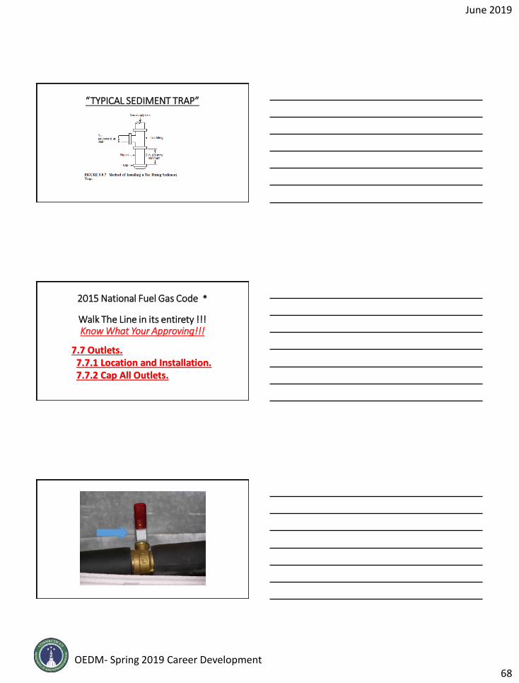
June 2019
OEDM- Spring 2019 Career Development68
“TYPICAL SEDIMENT TRAP”
2015 National Fuel Gas Code *
Walk The Line in its entirety !!!Know What Your Approving!!!
7.7 Outlets.7.7.1 Location and Installation.7.7.2 Cap All Outlets.

June 2019
OEDM- Spring 2019 Career Development69

June 2019
OEDM- Spring 2019 Career Development70
2015 National Fuel Gas Code *7.8 Branch Pipe Connections7.9 Manual Gas Shutoff Valves.
7.9.1 Valves at Regulators.
7.9.2 Valves Controlling Multiple Systems. Accessibility of Gas Valves.
Shutoff Valves for Multiple House Lines.
7.9.2.3 Emergency Shutoff Valves.“An exterior shutoff valve to permit turning off the gas supply to each building in an emergency shall be provided. The emergency shutoff valves shall be plainly marked as such and their locations posted as required by the authority having jurisdiction.”
Emergency Shutoff Valves. “COMMENT”
Shutoff valve for Laboratories:
NOTE: All Valves are NOT Good For Gas !!!
2015 National Fuel Gas Code *Section 7.9.2.4 Shutoff Valve For Laboratories.Each laboratory space containing two or more gas outlets installed on tables, benches, or in hoods in educational, research, commercial and industrial occupancies shall have a single shutoff valve through which all such gas outlets are supplied. The shutoff valve shall be accessible and shall be located within the laboratory or adjacent to the laboratory’s egress door and shall be identified.
NOTE: All Valves are NOT Good For Gas !!!
2015 National Fuel Gas Code *
7.10 Prohibited Devices
7.11 Systems Containing Gas Air Mixtures Outside the Flammable limits
7.12 Systems Containing Flammable gas-air mixtures
June 2019
OEDM- Spring 2019 Career Development71
2015 National Fuel Gas Code *7.13 Electrical Bonding and Grounding.
• 7.13.1 Pipe and Tubing Other than CSST. Each aboveground portion of a gas piping system, other than CSST, that is likely to become energized shall be electrically continuous and bonded to an effective ground-fault current path. Gas piping, otherthan CSST, shall be considered to be bonded when it is connected to appliances that are connected to the appliance grounding conductor of the circuit supplying that appliance.
2015 National Fuel Gas Code *• The following sections are new.
• 7.13.2* CSST. CSST gas piping systems and gas piping systems containing one or more segments of CSST, shall be bonded to the electrical service grounding electrode system or where provided, lightning protection grounding electrode system.
• 7.13.2.1 The bonding jumper shall connect to a metallic pipe, pipe fitting, or CSST fitting.
• 7.13.2.2 The bonding jumper shall not be smaller than 6 AWG copper wire or equivalent.
• 7.13.2.3 The length of the jumper between the connection to the gas piping system and the grounding electrode system shall not exceed 75 feet. Any additional electrodes shall be bonded to the electrical service grounding
2015 National Fuel Gas Code *
• electrode system or where provided, lightning protection grounding electrode system.
• Section 7.13.2.4 Bonding connections shall be in accordance with NFPA 70, National Electrical Code.
• Section 7.13.2.5 Devices used for the bonding connection shall be listed for the application in accordance with UL 467, Grounding and Bonding Equipment.
June 2019
OEDM- Spring 2019 Career Development72
2015 National Fuel Gas Code *
Chapter 8 Inspection, Testing, and Purging
2015 National Fuel Gas Code *
8.1 Pressure Testing and Inspection.8.1.1 General. 8.1.2 Test Medium8.1.3 Test Preparation8.1.4 Test Pressure.
2015 National Fuel Gas Code
• 8.1.5 Detection of Leaks or Defects.
• 8.1.1.5 A piping system shall be tested as a complete unit or in sections. Under no circumstances shall a valve in a line be used as a bulkhead between gas in one section of the piping system and test medium in an adjacent section, unless two valves are installed in series with a valved “telltale” located between these valves. A valve shall not be subjected to the test pressure unless it can be determined that the valve, including the valve closing mechanism, is designed to safely withstand the pressure.
June 2019
OEDM- Spring 2019 Career Development73
2015 National Fuel Gas Code *
• 8.1.5.2 The leakage shall be located by means of an approved gas detector, a noncorrosive leak detection fluid, or other approved leak detection methods.
• The following references have been removed: “Matches, candles, open flames, or other methods that provide a source of ignition shall not be used.”
NOTE: CORROSIVE PRODUCTS SUCH AS 409 CANNOT BE USED TO DETECT LEAKS!!!!!!!
2012 National Fuel Gas Code *
8.2 Piping System, Appliance and Equipment Leakage Check.
8.2.1 Test Gases8.2.2 Turning Gas On.8.2.3 Leak Check. 8.2.4 Placing Appliances and Equipment in Operation.
2015 National Fuel Gas Code
8.3 Purging requirements.
8.3.1 Piping Systems Required to be Purged Outdoors8.3.1.1 Removal from Service.
See Table 8.3.1
8.3.1.2 Placing in Operation. (Piping)See Table 8.3.1
8.3.1.3 Outdoor Discharge of Purged Gases.
June 2019
OEDM- Spring 2019 Career Development74
2015 National Fuel Gas Code *
• 8.3.1.4* Combustible Gas Indicator. Combustible gas indicators shall be listed and calibrated in accordance with the manufacturer’s instructions. Combustible gas indicators shall numerically display a volume scale from 0 percent to 100 percent in 1 percent or smaller increments.
•NOTE: WHO IS TRAINING YOU ON THESE METERS ?
2015 National Fuel Gas Code
• 8.3.2 Piping systems to be purged indoors or outdoors.
• 8.3.3 Purging appliances and equipment.
2015 National Fuel Gas Code
Chapter 9 Appliance, Equipment and Accessory Installation
9.1 General.9.1.1 Appliances, Equipment, and Accessories To Be Approved.

June 2019
OEDM- Spring 2019 Career Development75
2015 National Fuel Gas Code
• 9.1.2 Added or Converted Appliances. When additional or replacement appliances or equipment is installed or an appliance is converted to gas from another fuel, the location in which the appliances or equipment is to be operated shall be checked to verify the following:
• (1) Air for combustion and ventilation is provided where required, in accordance with the provisions of Section 9.3. Where existing facilities are not adequate, they shall be upgraded to meet Section 9.3 specifications.
• (2) The installation components and appliances meet the clearances to combustible material provisions of 9.2.2. It shall be determined that the installation and operation of the additional or replacement appliances do not render the remaining appliances unsafe for continued operation.
• (3) The venting system is constructed and sized in accordance with the provisions of Chapter 12. Where the existing venting system is not adequate, it shall be upgraded to comply with Chapter 12.
2015 National Fuel Gas Code
9.1.3 Type of Gas(s).9.1.4 Safety Shutoff Devices for Unlisted LP-Gas Equipment Used Indoors.9.1.5 Use of Air or Oxygen under pressure.9.1.6 Protection of Appliances from fumes or Gases Other than Products of Combustion.
2015 National Fuel Gas CodeChapter 9 Appliance, Equipment and Accessory Installation (cont)
9.1.7 Process Air
9.1.8 Appliance Supports
9.1.9 Flammable Vapors
9.1.10 Installation in Residential Garages
9.1.11 Installation in Commercial Garages
NEW Wording 9.1.11.2 Repair Garages “Appliances installed in repair garages shall be installed in accordance with NFPA 30A, Code for Motor Fuel Dispensing Facilities and Repair Garages.”
9.1.12 Installation in Aircraft Hangers
9.1.13 Appliance Physical Protection
9.1.14 Venting of Flue Gases
9.1.15 Extra Device or Attachment
9.1.16 Adequate capacity of piping
June 2019
OEDM- Spring 2019 Career Development76
2015 National Fuel Gas CodeChapter 9 Appliance, Equipment and Accessory Installation (cont)
9.1.17 Avoid Strain on Gas Piping9.1.18 Gas Appliance Pressure Regulators9.1.19 Venting of Gas Appliance Pressure Regulators (in part…..)• (2) Vent limiting means shall be employed on listed
appliance pressure regulators only. “Check the regulator installation instructions to confirm a vent limiting device can be installed on their regulator.”
2015 National Fuel Gas Code
9.1.20 Bleed Line for Diaphragm-Type Valves9.1.21 Combination of Appliances and Equipment9.1.22 Installation Instructions. THIS IS MOST IMPORTANT!!!!!!!9.1.23 Protection of Outdoor Appliance
2015 National Fuel Gas Code *
•NEW Section 9.1.24 Existing Appliances [adopted only for ANSI Z223.1-2015] Where an existing appliance is located within the conditioned space of an existing building envelope component, other than roofing material, is replaced or altered, the appliance installations shall be inspected to verify compliance with the provisions of 9.3 and Chapter 12. Where the appliance installations do not comply with 9.3 and Chapter 12, it shall be altered as necessary to be in compliance with such.

June 2019
OEDM- Spring 2019 Career Development77
2015 National Fuel Gas Code *
9.2 Accessibility and Clearance.9.2.1 Accessibility for Service.
• 9.2.1 Accessibility for Service. All appliances shall be located with respect to building construction and other equipment so as to permit access to the appliance. Sufficient clearance shall be maintained to permit cleaning of heating surfaces; the replacement of filters, blowers, motors, burners, controls, and vent connections; the lubrication of moving parts where necessary; the adjustment and cleaning of burners and pilots; and the proper functioning of explosion vents, if provided. For attic installation, the passageway and servicing area adjacent to the appliance shall be floored.
•NOTE: FOLLOW INSTALLATION INSTRUCTIONS!!!!
2015 National Fuel Gas Code *
9.2.2 Clearance to Combustible Materials.
9.2.3 Installation on carpeting.
2015 National Fuel Gas Code *9.3 Air for Combustion and Ventilation
9.3.2 Indoor Combustion Air9.3.3 Outdoor Combustion Air9.3.4 Combination Indoor and Outdoor Combustion Air9.3.5 Engineered Installations.9.3.6 Mechanical Combustion Air Supply9.3.7 Louvers, Grills and Screens9.3.8 Combustion Air Ducts

June 2019
OEDM- Spring 2019 Career Development78
2015 National Fuel Gas Code *
9.4 Appliances on Roofs9.4.1 General9.4.2 Installation of Appliances on Roofs
9.4.2.2 Appliances shall be installed on a well-drained surface of the roof. At least 6 ft (1.8 m) of clearance shall be available between any part of the appliance and the edge of a roof or similar hazard, or rigidly fixed rails, guards, parapets, or other building structures at least 42 in. (1.1 m) in height shall be provided on the exposed side.
NOTE: The requirements differ from the IMC!
2012 National Fuel Gas Code
9.5 Appliances in Attics9.5.1 Attic access
9.5.2 Work Platform
9.5.3 Lighting and Convenience Outlet
2015 National Fuel Gas Code *
9.4.3 Access to Appliances on Roofs
•9.4.3.2 Buildings of more than 15 ft (4.6 m) in height shall have an inside means of access to the roof, unless other means acceptable to the authority having jurisdiction are used.

June 2019
OEDM- Spring 2019 Career Development79
2012 National Fuel Gas Code
9.6 Appliance and Equipment Connections to Building Piping.
9.6.1 Connecting Appliances and Equipment. 9.6.2 Use of non metallic Gas Hose Connectors.
IndoorsOutdoor.
9.6.4 Connection of Portable and Mobile Industrial Appliances.
2015 National Fuel Gas Code *
•9.6.5 Appliance Shutoff Valves and Connections.•9.6.5.2 Shutoff valves serving appliances installed in vented fireplaces and ventless firebox enclosures shall not be required to be located within 6 ft (1.8 m) of the appliance where such valves are readily accessible and permanently identified. The piping from the shutoff valve to within 6 ft (1.8 m) of the appliance shall be designed, sized, installed, and tested in accordance with Chapters 5, 6, 7, and 8.
2015 National Fuel Gas Code
•9.6.5.3 Where installed at a manifold, the appliance shutoff valve shall be located within 50 ft (15 m) of the appliance served and shall be readily accessible and permanently identified. The piping from the manifold to within 6 ft (1.8 m) of the appliance shall be designed, sized, installed, and tested in accordance with Chapters 5, 6, 7, and 8.

June 2019
OEDM- Spring 2019 Career Development80
2015 National Fuel Gas Code
9.6 Appliance and Equipment Connections to Building Piping. (cont)
9.6.5 Quick Disconnect Devices. 9.6.6 Gas Convenience Outlets. 9.6.7 Sediment Trap9.6.8 Installation of Piping.
2015 National Fuel Gas Code
9.7 Electrical.9.7.1 Electrical Connections.
9.7.2 Electrical Ignition and Control Devices
9.7.3 Electrical Circuit
“Don’t forget State Boiler Code
requirements if they apply to
the installation!”
2015 National Fuel Gas Code
9.8 Room Temperature Thermostats
9.8.1 Locations
9.8.2 Drafts

June 2019
OEDM- Spring 2019 Career Development81
2015 National Fuel Gas Code
Chapter 10 Installation of Specific Equipment.10.1 General.
10.1.1* Application. Listed appliances shall be installed in accordance with the manufacturers’ installation instructions or, as elsewhere specified in this chapter, as applicable to the appliance.
*******Unlisted appliances shall be installed as specified in this chapter as applicable to the appliances.
NOTE: THERE IS FURTHER INFO ON UNLISTED IN SUB CHAPTERS DEPENDANT OF TYPE OF APPLIANCE
2015 National Fuel Gas Code
10.2 A/C Appliance ( gas Fired A/C and Heat pumps)
10.3 Central Heating Boilers and Furnaces
10.4 Clothes Dryers, includes Both Type 1 and Type 2 (Gas dryers)
10.5 Conversion Burners
10.6 Decorative Appliances in Vented Fireplaces
10.7 Gas Fireplaces, Vented
10.8 Non-Circulating Direct Gas-Fired Industrial Air Heaters
10.9 Recirculating Direct Gas-Fired Industrial Air Heaters
10.10 Duct Furnaces
10.11 Floor Furnaces
ECT ECT ECT!!!!!!
2015 National Fuel Gas Code
• 10.22 Room Heaters.
• 10.22.1* Prohibited Installations. Unvented room heaters shall not be installed in bathrooms or bedrooms. “With 2 exceptions”
• ICC RESIDENTIAL IRC DOES NOT ALLOW FOR SOLE SOURCE OF HEAT!!! MOST MANUFACTURER’S INSTALLATION INSTRUCTIONS ALSO DO NOT PERMIT THEIR UNVENTED UNITS AS A SOLE SOURCE OF HEAT!

June 2019
OEDM- Spring 2019 Career Development82
2015 National Fuel Gas Code
Chapter 11 Procedures to be Followed to Place Equipment in Operation.
This part deals with the placing of a gas utilization equipment into operation.
11.7 “Operating Instructions.” Operating instructions shall be furnished and shall be left in a prominent position near the equipment for the use of the consumer.
2015 National Fuel Gas Code
• Chapter 12 : Venting of Appliances
• 12.5.2 Plastic Piping. Plastic piping used for venting appliances listed for use with such venting materials shall be approved.
• 12.5.3 Plastic Vent Joints. Plastic pipe and fittings used to vent appliances shall be installed in accordance with the appliance manufacturer’s installation instructions. Where primer is required, it shall be of a contrasting color. “All known PVC manufacturer’s require solvent cement joints to be primed!”
2015 National Fuel Gas Code
• 12.6.4 Inspection of Chimneys.
• 12.6.4.1 Before replacing an existing appliance or connecting a vent connector to a chimney, the chimney passageway shall be examined to ascertain that it is clear and free of obstructions and shall be cleaned if previously used for venting solid or liquid fuel–burning appliances or fireplaces.
• 12.6.4.2 Chimneys shall be lined in accordance with NFPA211, Standard for Chimneys, Fireplaces, Vents, and Solid Fuel–Burning Appliances.

June 2019
OEDM- Spring 2019 Career Development83
2015 National Fuel Gas Code
• 12.7.3.1* Category I Appliances. The sizing of natural draft venting systems serving one or more listed appliances equipped with a draft hood or appliances listed for use with a Type B gas vent, installed in a single story of a building, shall be in accordance with one of the following: TABLE 12.7.2
• 12.7.3.3 Category II, Category III, and Category IV Appliances. The sizing of gas vents for Category II, Category III, and Category IV appliances shall be in accordance with the appliance manufacturer’s instructions.
2015 National Fuel Gas Code
• 12.11.7 Slope. A vent connector shall be installed without any dips or sags and shall slope upward toward the vent or chimney at least 1⁄4 in./ft (20 mm/m).
• Exception: Vent connectors attached to a mechanical draft system installed in accordance with appliance and the draft system manufacturers’ instructions.
2015 National Fuel Gas Code
Chapter 13 Sizing of Category I Venting Systems

June 2019
OEDM- Spring 2019 Career Development84
2015 National Fuel Gas Code
• 13.1 Additional requirements to single appliance vent
• Venting Tables 13.1(a) through 13.1(f)
• 13.1.11 Chimneys and vent locations
Table 13.1(a) through 13.1(e) shall be used only for chimneys and vents not exposed to the outdoors below the roof line.
Use of Office of Education and Data Management (OEDM)training materials must be approved in writing by the State ofConnecticut, Department of Administrative Services’ Office ofCommunications. In approving of such use, the State ofConnecticut assumes no liability associated with such use,including, but not limited to, the user’s dissemination of anyinaccurate information or interpretation in connection withits use of these training materials. Use of the trainingmaterials is at the sole risk of the user, and the State’sapproval of the use does not constitute an endorsement ofthe user or its intended use.
Use of OEDM Training Materials
251
Questions
Thank you !