I SICKLE BAR MOWER - gravelymanuals.com · r GENERAL INFORMATION Your Haban Sickle Bar Mower is the...
21
- ~ ~\ QU4(~ .}~:'-,I- - ~ @ '-,. MODEL 413 I SICKLE BAR MOWER ATTACHMENT ~GRAVELY FOR 800 SERIESTRACTORS ( \ ~ ~ \ """, .","'c" , " ,~\ '1;,;,!", """'"" OPERATION \\c, ~,," "c'\ & ,\, SERVICE '\ MANUAL j With Repair Parts List ": , '$ .~c \ \ HABAN MANUFACTURING COMPANY Racine, Wisconsin t ..::!:' Serial No. (199-805 -) Form 8662 (4/73) ~~~ ~;;;;;;;;;;;;; ~ ' ~ @ ~ , :4(1 N: j --" , , " ~ '., ~ , "'n,." ~- ,- ~- .'l
-
Upload
duongnguyet -
Category
Documents
-
view
218 -
download
0
Transcript of I SICKLE BAR MOWER - gravelymanuals.com · r GENERAL INFORMATION Your Haban Sickle Bar Mower is the...

-
~ ~\ QU4(~.}~:'-,I- -
~
@'-,.
MODEL 413
I SICKLE BAR MOWERATTACHMENT
~GRAVELYFOR 800 SERIES TRACTORS
(\ ~ ~\ """,.","'c", " ,~\ '1;,;,!", """'""
OPERATION \\c, ~,,""c'\& ,\,
SERVICE '\
MANUALj With Repair Parts List
":, '$ .~c
\\
HABAN MANUFACTURING
COMPANY
Racine, Wisconsint ..::!:' Serial No. (199-805 -) Form 8662 (4/73)
~~~~;;;;;;;;;;;;; ~ ' ~ @~, :4(1 N: j --", , " ~'., ~, "'n,."
~-
,- ~- .'l

,
r GENERAL INFORMATIONYour Haban Sickle Bar Mower is the finest Performance of the sickle knife depends onsickle bar mower available anywhere. Designed the following points, all of which are important:specifically for your compact tractor with all (1) sharpness of sickle knife; (2) wear platecontrols convenient to the operator, itls rugged adjustment; (3) straightness of knife bar; (4)construction assures you long life and highest hold-down clip clearance; (5) speed of sickle
performance. The mower cuts a 4811 swath knife; (6) lead adjustment of sickle bar; (7)and operates from the tractor PTO. cutting pitch of shear fingers.
Keep this manual available for ready reference. TRANSPORT POSITION:It has been carefully prepared to instruct youin operating, maintaining and lubricating your The sickle bar mower can be transported fromHaban Sickle Bar Mower, Emphasis has been one location to another by raising the unit withplaced on safety and operator protection. How- the lift handle and locking it into positionever, careless and negligent operation can still as illustrated on page 5.result in serious injury to persons and property .It is very important that each operator fully A ALWAYS INSTALL KNIFE GUARD ONunderstands the contents of this manual for MOWER BAR WHEN TRANSPORTING.safe dependable operation and to prolong the A ALWAYS OPERATE AT CAREFULlife of the equipment. SPEEDS IN TRANSPORTING AND AVOID MAK-
ING SUDDEN OR SHARP TURNS WITH THEWhen in need of parts, be prepared to give MOWER IN RAISED POSITION.your dealer the serial numbers shown on themower nameplate located on the frame, Write
CONTENTSthe serial number in the blank shown.
HABAN MODEL 413 SICKLE BAR MOWER SAFETY. 0 0 ...3 & 18OPERATION. 00' .0 ..0 .0 ..4-10
SERIAL NO. TRANSPOR TING MOWER. 5ADJUSTMENTS
OPERATING TRACTORS WITH HYDROSTATIC V-Belts 0 00""'0' 0 0 0 7OR GEAR TYPE TRANSMISSIONS Sickle Knife. ...0 0 0 0 0 0 0 .0 ..8
\B t tt ' It ' ll b bt ' d b OPERA TING MOWER. ...0 0 .0 ..9-10
~ es cu mg resu s WI e 0 ame yoper-I ating tractor at 3/4 to--iull engine speed. With SERVICE TIPS. .0 .0 .000 .0 ..0 o. 10: hydrostatic transmission adjust tractor ground MAINTENANCE. 0 .0 0 11! speed through hydrostatic control pedal, With SET UP '.0' 0" ...12-18! gear type transmissions regulate tractor PARTS LISTING 0 ..0 .0 0 19-23
ground speed by selecting proper gear ratio,usually second or third gear.
SPECIFICATIONSLength. 73"
f Mowing in extremely rough areas requires Clearance Required , .3": reduction in tractor speed, Cutting Width. , .Mows 48 "Swath
Overall Depth 24"
When cutting brush larger than 1/211 diameter, Drive .Belt Driven from Tractor P.T.O.
slow forward speed of tractor prior to cutting ~~:;:ns;~~ '.'.'.'.'.'.'.'.'.'.'.'.'.'F'r~-~i~a't;~g','~~r;~~ ':ue~~e~~:brush. It may be necessary to stop tractor Mounting .Swivel, Vibration-Dampeningmovement when sicke bar makes contact and Cutting Speed. 900- 1100 strokes per minuteallow the sickle knife to cut through the brush Stroke. , .., Full 3" widthmaterial. It is not recommended to attempt to Shear Knives HighCarbon St.eel
c,ut material exceeding 1-1/2 to 211 in diameter, ~::;i~:1 ~~iu~~~~~~ '.'.'.'.'.'.'.'.'1'3'5'0'~;~ 'be;~:o~~C:i:~'tn:900 vertical-lever controlled
Transport Position .Pin-Locked for Transportl' Automatic Spring-Loaded "Swing Back" device protects against damage from solid objects
.2 Construction. AII-Steel, with Anti-Friction bearings

OPERATIONFor starting or stopping your Sickle Bar Mower. NEVER leave the tractor engine running whenRefer to tractor instruction manual on proper dismounting from the tractor. De-clutch frontmethod of clutching and declutching attach- tractor P. T .0. clutch as well.ments used with tractor.
Always stop tractor engine when dismounting,from tractor set parking brake or place tractortransmission in park position. Always de-clutchfront P. T .0. whenever stopping tractor engineor tractor operation.
LIFT SPRING TENSION WITHPIVOT HANDLE IN OPERATING ~POSITION, SHOULD CARRYINNER SHOE (F) 1/2"OFFGROUND. SHOE CLEARANCE \\," 'FROM GROUND CAN BE IN- c~, ~CREASED BY DROPPING LINKSIN LIFT CHAIN (D). ..CUTTINGCONDITIONS IN SOME AREASMAY R~UIRE INNER SHOECLEARANCE FROM GROUNDOF APPROX. 2" WHEN INOPERA TING POSITION ONLEVEL GROUND.
HOLD DOWN CLIPSSHOULD HAVE1/32" CLEARANCEFROM SICKLE KNIFE
...PIVOT LIFT HANDLETO INCREASE TENSION IN THIS POSITIONON TORSION SPRING, IF TORSION SPRING IS LOOSE, FOR OPERATION. PUTTIGHTEN BOLT. INCREASED SICKLE BAR WILL BE HARD TO HANDLE IN "UP" POSI-TENSION ~EMOVES WEIGHT LIFT. IF TORSION SPRING IS TION WHEN DETACHINGFROM-o'(iTER SHOE. LESS SET TOO TIGHT, OUTER END OF MOWER FROM TRACTOR.TENSION ADDS WEIGHT SICKLE BAR WILL HAVE A TEND-
Fig. 1 TO OUTER SHOE. ENCY TO BOUNCE IN OPERATION.
Fi .2 A Keep lock strap (H) in plac e. LIMIT STOP (Figure 2) NORMAL CUTTING:Thelimit stop (5) should be set with LOCK OUTSTRAP (H) in place on slot. This will limit thetravel of the Cutter Bar in cutting positionto approximately 700 above ground level andallow it to function to its maximum below groundlevel. The lift arm must always be set inoperating position (B) when cutting.
~'"VERTICAL CUTTING (900 only) The lockoutstrap (H) must be removed to cut 900 aboveground level or vertical. When finished withvertical cutting, bolt strap (H) back in place.The lift arm must always be set in operat-ing position (C) when vertical cutting.
CAUTION: Make sure lockout strap (H) is boltedsecurely in place when finished with verticalcuttings.

ri~OPERATION
TRANSPORTING MOWER:
Stop tractor engine and disengage tractorI P. T .0. clutch. Install sickle knife cover (J)
using retaining strap to secure cover to bar.Set lift handle in transport position (H). Standin back of mower, raising mower bar withright hand to vertical position. Insert trans-port pin (K) as illustrated by sliding pin downfrom vertical to horizontal position as shown.Let pin slide through hole in strap (L) tolock in place. Avoid sudden or sharp turnswith mower in transport position (Fig. 3).
TO CHANGE SICKLE BAR MOWER FROMT RAN S PO R T POSITION TO MOWINGPOSITION:
Stop tractor engine. Standing behind mowerpush inward on mower bar, slide transport pin(K) out of strap (L) and turn strap to verticalposition to lock out. Lower sickle bar toground. Loosen retaining strap (C) and removesickle knife guard. Always install sickle knifeguard when mower is not in use or whentransporting unit.
WHEN CUTTING ON LEVEL GROUNDBefore operation,check complete unit for anylooseness which may have occured in shipping.Unit should then be operated a short periodto check for proper as,sembly and adjustments
.before actual cutting b'egins. stop and recheckFIg.3 all parts after 30 minutes of operation and
retighten loose parts. Also follow lubricatinginstructions found on page 11. Operate tractorat full throttle. It will be necessary to regulatetractor forward travel to meet existing cuttingOPERA TING conditions, which can vary greatly, depending
POSITION on material that is being cut. RUN INNERB ~--= SHOE APPROXIMATELY 4" AWAY FROM
I:' PREVIOUS SWATH EDGE FOR BEST PER-l FORMANCE. Cutter bar has additional width
of cut to compensate for overlay. Care mustbe exercised not to operate tractor at ex-cessive ground speed when cutting rough ter-rain. The lift arm must always be set inoperating position (B) when cutting.
Under severe conditions the sickle knives2 should be sharpened after every four hours
of operation. Additional knives and rivets areF. 4 available for repairs, which makes it possibleIg. to always have a sickle knife assembly in
good repair if one becomes damaged or worn.5

OPERATIONCUTTING (900 Vertical to 450 above level) To disengage safety break-back manually, in-
When cutting 90 degree vertical to 45 degree s~rt screw driver at. (G) and p~y break-back
above level, the engine throttle should be set pivot open-at sam~ time push sickle bar backapproximately 1/811 open. The lift handle must to release catch.. Fig. 6.
be set in transport position. (A). (Fig. 5).
A NOTE: This should be done by an experi-
enced operator only, using extreme caution.
SO
Fig. 7
.KNIFE POINT POSITION (Pitch Angle (Fig. 7)
Fig. 6
To adjust pitch of sickle bar (E), loosen bolts
(G) and bolts in tie rod (P). Install sickle
knife guard and raise sickle bar to vertical
position. Push forward to increase downward
pitch of sickle bar. Normally sickle bar (E)
should have a downward pitch of about 1/411
from carriage plate (A), Fig. 7. When cutting
extremely heavy, tangled or matted grass, it
may be necessary to increase downward pitch
of sickle bar. After desired setting is reached
retighten bolts (G) and bolts in tie rod (P).
AUTOMATIC BREAK-BACK (Figure 6) OPERATINGPOSI TION
The break-back automatically releases sickle B
bar into break-back position when hitting ob- ~~ ~ .
struction. The sickle-mower unit should be
immediately DE-CLUTCHED. Return sickle B EAK- A
bar to normal cutting position, engaging break- ~OSIT?ONCK
back. This may be done by reversing tractor with sickle bar on ground, or manually. T Unwarranted or frequent break-back releases '" """""
\ ~I ~ndicate tension on the spring (F) should be ;;: "" SWA TH
increased. MOWING EDGE1 POSITION 2
6 --" --Co

OPERATION..I , "'""
%,"'",'!!!! ',,%!"',' "\,,,
%"'"
I~I
; I
""\!
Fig.9
If additional tension is needed on drive belt (V),Fig. (10), loosen four bolts (H) and jam nut onadjusting bolt (J). Turn adjusting bolt until pro-per tension is obtained. Retighten jam nut ands four bolts (H).el
~d SETTING LEAD OF SICKLE BAR:)II
(Fig. 8) Improper lead adjustment of sickleg bar assembly will create excessive side draftit on tractor and poor cutting action, as well as:h possibly plugging sickle knife. Outer end of:d
sickle bar at (1) should lead inner end (2)). by two inches as illustrated in (Fig. 8). Toadjust lead, loosen three vertical bolts (C)in plate (A) and two set screws in tie rod (P)
Fig. 10 (Fig. 9). Adjust cutter bar (3) to lead settingas illustrated in (Fig. 8), by pushing outer endADJUSTMENT OF PITMAN AND MOWER of bar forward. Slots in carriage plate (A)
DRIVE BELTS. will adjust accordingly to allow for changeIf additional tension is needed on Pitman drive in lead setting. (Fig. 9). When proper settingbelt (8), loosen bolts (C) and bolts in tie rod is obtained tighten vertical bolts (C) and two(P). Loosen jam nut on adjusting bolt (W) and set screws in tie rod (P). IMPORTANT: Pro-turn adjusting bolt until V-belt (S) is tightened. per V-belt tension will allow approximately
C ' (Proper tension will allow approximately 1/211 1/211 deflection of V-belt when applying firmI deflection of V-belt when applying firm finger finger p!essure midway between pulleys (Fig.pressure midway between pulleys). Tighten jam 9a).nut on adjusting bolt and secure bolts (C) andbolts in tie rod. 7

~- OPERATION
51 ckle KnifeAdjustment
Fig. 10Check the position of the forward ends of thelive knife sections (B) to make sure that they LIVE SICKLE SEc;:rIONSTO PROTRUDE 1/32"protrude past the forward ends of. the shear to 1/16" OVER SHEAR PLATE.finger plates (E). For cutting loose precut KNIFE CLEARANCE (Fig. 10)hay, dense, fine and loose under growths, etc.,without clogging, the live moving knives must If the knife fits too 100 s ely, in most casescontact the material ahead of any stationary clearance can be obtained by hammering downshear-plate. 1/3211 to 1/16" protrusion of the or prying up the front end of the hold downknife is sufficient. If your "wear-plates" (A) clips (F). The suggested method is to removeare worn half way thru on the front edge, the knife assembly. Reinsert the knife andmoving the wear plate forward will place the adjust each clip as it is reached, for the en-sickle in the proper position. If the wear tire length of the bar. Bend each clip up orplate is worn too much for m9.king the proper down as required. The approximate clear-adjustment they should be replaced. ance to be maintained should not exceed 1/32".
Fitting these clips too tightly will cause bind-KNIFE ASSEMBLY REMOVAL ing or scoring, exc essive vibration and chatter.
Lubricate freely.When it becomes necessary to remove theknife for sharpening.. section replacement or CUTTING FAILUREcomplete knife replacement, remove the boltsholding the knife head to bar and slide knife A. Check sharpness of knife sections.out of guard assembly.
1. If sharpening is necessary a sickleALIGNMENT OF'LEDGER PLATE SURFACES grinder with a holder should be used
for this operation to maintain correctRemove the knife assembly and check all shear grinding angle. (Same as original)fingers for alignment of surfaces. The align-ment may be checke~ using a straight edge 2. Replace damaged sections.or drawing a string tightly across these sur-faces. Any shear finger being too high will B. Check fit of knife sections to shear fingerscreate excess clearance between the shear and wear plates. If the knife sections arefinger and the knife sections. Misalignment sharp, clean cutting is entirely dependentcan be corrected by bending shear fingers up upon the following:or down, as required. Hammer only on solidportion of guard beyond the lip. 1. Alignment of shear finger surfaces.
2. Wear plate adjustment. iWEAR PLATE ADJUSTMENT (Fig. 10) 3. Straightness of knife bar. I
4. Pitch of shear fingers. IThe wear plates (A) support the back of the 5. Hold down clip clearance.knife sections (B) and guide the knife bar in 6. Proper lead setting of mower.the shear finger recess. Wear plates have 7. Improper speed of sickle knife in re-elongated holes for adjustment against the lation to forward travel of tractor.knife bar (C) to prevent it from drifting for-ward and backward. Adjust by loosening the 'Be sure the sickle sections are sharp at allguard bolts (D) and sliding the wear plate times and held close to the shear fingers byforward against the knife bar. Avoid a tight the sickle slips. Be careful, however, offit. Check the top surface of the wear plate having them too tight as this will cause bind-with the shear finger surface (E). These two lng. Always lubricate well with oil at the pointsurfaces must be even. A low wear plate should t\n the bar and shear finger assembly wherebe shimmed. the clips contact the knife assembly.
)cf8 _ II -c:": -' c';',:: Form 8512 (4/1

OPERATIONOPERA TING THE MOWER: Test pattern cutting will soon show you the
most appropriate way to approach the task.PRESTARTING INSPECTION: Remember, the proper settings, a sharp sickle,
correct forward speed, and good general main-1. Be sure mower has been properly assembled tainance will enable you to cut any reasonable
to tractor. Set-up instructions start on page patch of grass with satisfaction. Overlooking12 .anyone of the above points may detract from
2. Be sure mower is properly adjusted. the machine1s performance. A few points are3. Check condition of sickle sections. Keep listed below:
them sharp.With tractor engine throttle set just above idle,engage front tractor P.T.O. clutch. Always OPERATING SICKLE BAR MOWER ONadvance throttle to full position whenmowing TRACTORS WITH HYDROSTATIC DRIVE:on level ground.
Proper ground speed for mowing depends uponSTOPPING THE MOWER: (1) the height, density, and type of grass to be
cut and (2) field or yard conditions. When mow-Refer to your tractor manual for starting ing, always operate engine at full throttle.and stopping tractor attachments. This is necessary to maintain proper sickle
speed and to cause maximum flow of air tocool engine.
METHOD OF MOWING: Operation of hydrostatic drive tractors enableyou to easily obtain the proper ground speed
Before mowing a new plot of grass, always needed for best mowing performance with thestop to analyze the area for best mowing sickle bar mower. A short amount of testingprocedure. Consider also the height of grass when starting to mow in the various conditions
(: to be mowed, type of terrain (level, hilly or that you find, will enable you to determinepitted), as well as the presence of rock or the most appropriate speed for that particulartrash. Each condition will require certain condition. Too fast a forward ground speedadjustments or precautions, as outlined in the will cause problems as outlined in paragraphfollowing pages. three as listed in operating tips (page 10).
it. CAUTION: Before servicing machine, dis- .engage power, stop engine, and disconnect Exce~tIonally tall .g~s OrtoWeeds, t uneven .
k 1 bl terram, may requIre you opera e yourengme spar p ug ca e.
tractor at a much slower speed than you wouldit. CAUTION: Pick u all rocks, stones and normally use. On the other hand sparse ~eeds
.p. ..etc., may enable you to operate at a hIgherother debrIs you can fmd before mowmg m af f d d th ld 11.rate 0 orwar spee an wou norma ynew area. Enter the area cautiously. be used under regular cutting conditions.
Sickle bar mower can operate from 90 degreevertical to 45 degree below horizontal. It GEAR TYPE TRANSMISSIONSmay be necessary to release some tension onthe torsion spring to allow mower bar to Generally, best mowing will result when oper- !drop to lowest angle. There should be a 1/3211 ating the tractor shift lever in second or thirdclearance between sickle sections and hold gear and engine operating at full throttle. Tall
.down clips. If several years of dead grass grass or weeds may require you to operate in
.has accumulated in areas being cut, first gear in some conditions.particularly on hills or slopes, it may be1 necessary to cut against the slope due to dead
~ material leaning forward, thereby not allowingthe sickle to cut cleanly.
-.:It , I ,
.J "e ):'[1\
~ (4/72) 9

.-~I' ~::
OPERATION
A REMEMBER SAFETY PAYS.Always slow down the forward speed of the CAUTION: When mowing over rough groundtractor at the time of making a sharp turn, or on hillsides, the hydrostatic transmissioncutting on a radius, on banks or slopes or allows selection of safe ground speed at fullother uneven terrain. engine throttle.
.SERVICE TIPSPROBLEM SOLUTION
1. Cutter bar outer shoe bounces Adjust torsion spring as indicated in figure 1,or digs into ground surface. (Page 4).
2. Inner shoe dragging on Raise inner shoe assembly by adjustment ofground. lift spring (Fig. 1, page 4). Make sure lift
chain is properly assembled.
3. Mower does not cut cleanly. Adjust forward travel of speed to coincidedrags hay under sickle, cut- with sickle knife action. Check setting of holdting pattern shows blank or down clips (Page 8). Check lead setting (Seeskipping points. page 7).
4. Bunching of cut material in Inner shoe is being run too close to edgefront of inner shoe after ad- of previous swath. Allow approximately 411justment of lift spring. overlap. Fig.4 (Page 5)
5. Failure to cut grass and Check clearance of sickle to guards -fitweeds. should be snug, 1/3211 clearance. Tap metal
hold-down clips with hammer to adjust. Sharpensickle section if dull. Check pitch of guardsand lead of sickle bar.
OPERA TION.-/ Cutting of heavy, short undergrowth, inter-mingled with tall weeds may require a slowerSERVICE TIPS FOR SICKLE BAR MOWER forward speed than would normally be used
OPERA TION WITH HYDROSTA llC DRIVE for weed mowing. Be certain that your sickleTRACTORS:' assembly is always kept sharp.Operation of hydrostatic drive t r act 0 r senables a wide variance of forward speed at A CAUTION: Never attempt to forcea single throttle setting without necessarily the sickle bar mower to raise, if the outertaking into consideration the type of material end of the bar is lodged or caught in foreignthat is bei~g cut. L~sted ?el~w ~re some of the debris, dirt or heavy underbrush. Give yourtell-tale s~gns WhICh wIll ~ndIcate when you tractor and the equipment every possibleare operatIng ~our tractor m excess of reas- opportunity to operate efficiently. Attempt toonable performIng speeds: reverse tractor or move forward carefully
,until sickle bar is released from entangle-1. Jagged or uneven cutting indicates too fast a ment or --stop engine --set parking brake -forward ground speed. disengage PTO clutch, dismount from tractor
and release mower bar from entanglement2. Plugging sickle assembly could be created manually, then proceed.by either excessive forward speed, improperlea,d adjustments, improperly installed hold Remember, always keep engine running at fulldown clips, dull sickle or incorrect pitch angle throttle when mowing -regulate forward speedof sickle bar. through hydrostatic transmission control.
10 _I

MAINTENANCE,,-Zerk
fittings shouldbe grea sed withregular pressuregun lube.
LUBRICA TION @
Before starting, it is important that the machineis thoroughly lubricated. Give each fitting afew shots of grease. Grease all points atone-hour intervals the first two days of MAINTENANCEoperation and then twice each day there-after. Entire unit should be greased at least Ad~ust. thTI belt tensio,n described under "B.elt
-once each four hours during continous oper- AdJustmg on pages ~d 14. Proper tensIonr ation. allows for approximately one-half inch deflec-d tion when finger pressure is applied midwaye The following fittings require grease every four between pulleys. Check V -belt for wear. Re-
hours of machine operation: place worn belts with belts supplied only byHaban.
(A) Pitman crank pine (B) Crankshaft CLEANINGr~
The following points require oilcan lubrication A CAUTION: Before servicing machine, dis-'e as shown: engage power, stop engine, and disconnect:
engine spark plug cable..0 Every two hoursly (C). Pitman head '.~- (D). Sickle clips For best and la~tmg results,. the machIne-(G). Wear plate and moving points should have all dIrt accumulatIons removed)r Every eight hours from sickle bar. Do not allow machine tont (E). Two inner shoe pivots stand for long periods without cleaning. In-
(F). Torsional lift spring side storage will also prolong its operating11 (H). Transport spring pulley expectations.I (J). Spring release pivot assembly~d (K). Spacer break away housing(L). Quick pin assembly
11
---
SET UP
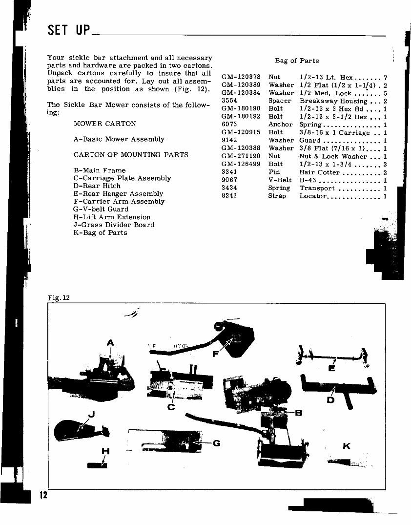
fYour sickle bar attachment and all necessary Bag of Parts i
parts and hardware are packed in two cartons. .
Unpack cartons carefully to insure that all GM-120378 Nut 1/2-13 Lt. Hex 7
parts are accounted for. Layout all assem- GM-120389 Washer 1/2 Flat (1/2 x 1-1/4) .2
blies in the position as shown (Fig. 12). GM-120384 Washer 1/2 Med. Lock. ..:...5
3554 Spacer Breakaway Housing. ..2The Sickle Bar Mower consists of the follow- GM-180190 Bolt 1/2-13 x 3 Hex Hd 1
ing: GM-180192 Bolt 1/2-13 x 3-1/2 Hex ...1
MOWER CARTON 6073 Anchor Spring 1
GM-120915 Bolt 3/8-16x 1 Carriage ..1
A-Basic Mower Assembly 9142 Washer Guard 1
GM-120388 Washer 3/8 Flat (7/16x 1) 1CARTON OF MOUNTING PARTS GM-271190 Nut -Nut & Lock Washer. ..1
GM-126499 Bolt 1/2-13 x 1-3/4 3B-Main Frame 3341 Pin Hair Cotter. 2
C-Carriage Plate Assembly 9067 V-Belt B-43 1
D-Rear Hitch 3434 Spring Transport 1
E-Rear Hanger Assembly 8243 Strap Locator. 1
F-Carrier Arm Assembly
G-V-belt Guard
H-Lift Arm Extension
J-Grass Divider Board
K-Bag of Parts
Fig. 12
A
~ \ " ' \,
, "r' ~E '~.,
'.~IT~~ ~B
8.1.,H-'
12
---

--~
SET UP[
SICKLE BAR ASSEMBLY (Fig. 13)
I Remove plastic .ratchet strap holding jackshaft To attach the sickle bar breakaway latchto main frame support plate (C). Place carriage frame assembly (H) to the breakaway housingplate (B) beneath main frame support plate, (B), insert spacer (J) into breakaway latchwith vertical plate of (C) against adjusting bolt frame hole (K). With the spacer in place,(A). Align slotted holes. Insert three 1-1/2 x align hole (K) with hole (L) in breakaway1-3/4 carriage bolts down through jackshaft housing plate (B) and insert 1/211 x 311 hex.straps, slotted holes in plates (B) and (C) and head bolt. Secure with lock washer and nut insupport brace (F). Place lock washer and nuts (Fig. 13).on bolts and finger tighten only.
\GRASS DIVIDER BOARD (J) goes on the endofsickle bar. Remove hex. nut and placegrass divider (J) over carriage bolt and securewith hex. nut (Fig. 12).
NOTE: Torsion spring (J) should not be attachedto torsion adjusting bolt (K) at this point(Fig. 15).
Fig. 13
.J
FI
13

-
SET UPFig. 14
,
y
'yf
,
!
V-BELT INSTALLATION I
Leaving mower assembly in break-back posi-tion, install V-belt (S) as follows: Removehousing stop cover (U). Slide V -belt ontopulleys (Y) and around crank-shaft pulley (L)as shown. Align assemblys (B) and(C) so they are evenly together, then tightenbolts (D) and reset anchor bolt (A) to touch endof carriage plate as shown (Fig. 14). Retightenset screws (S) in tie rod.
R -c
1 J:c~c
F' 15 ADJUSTMENT OF PITMAN AND MOWERIg. DRIVE BELTS
Swing latch frame (H) into breakaway housing(B) as shown (Fig. 15). Place and align If additional tension is needed on Pitman drivespacer (M) between two holes (N) in break- belt (S), loosen bolts (D) and bolts in tie rodaway housing. Place angle clip (P) over hole (P). Loosen jam nut on adjusting bolt fA)(N). Keep angle clip in the position as shown and turn adjusting bolt until V -belt (S) is tight-(Fig. 15). Thread 1/211 x 3 1/211 hex. bolt ened. (Proper tension will allow approximately(R) down through hole (N). Loosen set screws 1/211 deflection of V -belt when applying firm
; I (S) in tie rod (T): adjust tie rod to align with finger pressure midway betweenpulleys). Tight-, bolt. Keep lock washer and hex. nut loose at en jam nut on adjusting bolt (A) and bolts (D)this point. and bolts in tie rod.
14
SET UP
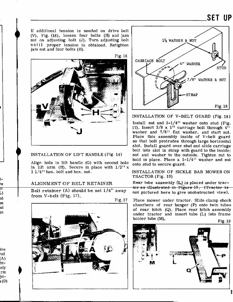
If additional tension is needed on drive belt(V), Fig. (16), loosen four bolts (H) and jamnut on adjusting bolt (J). Turn adjusting boltun t i I proper tension is obtained. Retightenjam nut and four bolts (H).
Fi .16
WASHER & NUT.Fig.
18
INSTALLATION OF V-BELT GUARD (Fig. 18)Install nut and 1-1/411 washer onto stud (Fig.
...17). Insert 3/8 x 111 carriage bolt through 411'-' washer and 7/811 flat washer, and start nut.
Place this assembly inside of V -belt guardso that bolt protrudes through large horizontalslot. Install guard over stud and slide carriagebolt into slot in strap with guard to the inside;
INSTALLATION OF LIFT HANDLE (Fig. 14) nut and washer to the outside. Tighten nut tohold in place. Place a 1-1/411 washer and nut
Align hole in lift handle (G) with second hole onto stud to secure guard.in lift arm (H) .Secure in place with 1/2 II x1 1/411 hex. bolt and hex. nut. INSTALLATION OF SICKLE BAR MOWER ON.TRACTOR
(Fig. 1.9)1-I'e ALIGNMENT OF BELT RETAINER Rear tube assembly (:l.(lis placed under trac-
;0 ." tor as illustrated in Figure 19. (Tractor isL) Belt retamer (A) should be set 1/4 away not pictured here to give unobstructed view).from V -belt (Fig. 17).ld Fig. 17 Place mower under tractor. Slide clamp shock~~
absorbers of rear hanger (P) onto twin tubes[l of rear hitch (Q). Place rear hitch assembly~n under tractor and insert tube (L) into frame
holder tube (M). Fig. 19ive~od
[A):ht-
;ely ~lrm ,rht-.s (D)
\ 1~
--

r~
I. SET UPI
Fig.22Lift rear of mower and place bar of rear intotractor mounting brackets (T). Swing down lock-ing straps (V) and secure in place with haircotter pins.
Fig.20
TORSION SPRING HOOK-UP
! Raise mower bar into vertical position and in-r l stall torsion spring adjusting bolt (U) to torsion
spring spur (V) as illustrated (Fig. 23).Fig.23
,rRaise front of sickel bar, placing axle betweenaxle straps (R) of mower insert locating pins(S) and secure with hair cotter pins. '
Fig.21
l
",
ATTACHING PTO (Fig. 22)
Slide end of mower PTO (D) over tractor Next, install carrier arm assembly (A) (Fig. 23)PTO spline (E) being sure to align h 0 I e s. by inserting carrier arm into mounting pocket
i Insert pin and secure with clip spring. (Note: (B). Push carrier arm into pocket (B) untilFor easiest installation grease mating parts carrier arm button stop rests against end of
.of mower PTO halves and tractor PTO spline). pocket mounting tube.
16

__SETUP
INSTALLA TION OF LIFT CHAIN AND SPRING TRANSPORTING MOWER:ASSEMBLY TO CARRIER ARM (Fig. 23).
Install sickle knife cover (J) using retainingstrap to secure cover to bar. Set lift handle
Lift chain (C) should be threaded over carrier into transport position (H). Stand in back ofarm pulley (D). NOTE: Be certain that ec- mower, raising mower bar with right hand tocentric arm on carrier pulley is in !IUpll vertical position. Insert transport pin (K) asposition at this point. Anchor clip (E) is posi- illustrated by sliding pin lever down fromtioned at angle shown and lift spring (F) is vertical to horizontal position as shown byattached to angle clip (E). To connect lift arrow. Let pin slide through hole in strap (L)spring to lift chain, remove all slack from to lock in place. Avoid sudden or sharp turns withchain, then connect lift spring (F) to lift chain mower"in transport position (Fig. 24-25).(C) so the chain is snug. Then push pivot arm .assembly into operating position (G) as illus- Flg.25trated in (Fig. 23).
!n- Inner shoe of sickle should then be approxi-,Ion mately 1/211 off floor at this point. For added
clearance, drop additional links of chain. Hav-ing inner shoe approximately 1/211 off flooror ground level when sickle is not operatingwill allow inner shoe to float more easilyover uneven terrain, precut material, andother obstructions.I
LIFT HANDLE POSITIONS: (Fig. 24 & Fig. 25)
Lift handle should be set in top notch asillustrated for operating sickle. Setting (H)is for transport position. Stop tractor engine,and disengage front tractor PTO clutch whenever dismounting from tractor (Fig. 24).
Fig.24
TRANSPORT POSITION
OPERA TION CHECK LIST
1. Make sure lift operates smoothlyI 2. Check chain tension
3. Check knife clearances:.23) 4. Check shear bar bolts,cket 5. Check bolts that hpld main cylinderuntil to the base of the machineld of 6. Check all other bolts to make sure
they are tight
1~

O~""f
f ~ir I ~
60
48E250 / 50~ / 49 31
..@/ ~...@, 46 I 33 J / 32 -i 8,/' (\.' /45 ~ ~-34 I I ,/ ~ '\.~ ~
10 >b ~ 43 ~.:' M / /53 47bco1 "",29~\ '12 9 I 37'0 19~ 40 $/ ,,~11 ff!!:i1-/ ('" 36, ~ ~ 7 ~ ~917 46
~ ~ 52 ~1 JP ~~~:~{~ ~ ,~2 28 :-- ~ .//"",-/ /' ~~/_"'\ "-,~ ~ 35~\Y'" ~~I.J' ~2~J rl~!5 4950/ ./ ) /./ ",-' ~" / / 48/' & '" , /" / @~ //' ~ I' '- '~ '!I'~"" "" 44', ~ ~ 23 ~ /'
7 .'20 $\ ~"" ., .\ 21 ("" 13 ../17 .., "22 ~ / \ '~ .'" "
54t) " ,..-! , ~ "\6 '- "
,,' I 39 -49 ',I ~ ",,/53-(jd '", '" /' "" 15"11~ '" "" ~~ 3~ ,-, .6 3 i /@ ~ ~ ~ ~ " /' I ~ ' 17 / 7 0 '" ~~ rG
I 39 56 I ~ I 14/ ..-@_39 58 57 ~ 65 Q 'j1 ,I' ~ '-
~tit~39 '18? /',/ ~ .J : /"iJ17-- @ I 17 ~~.:::.~ m'Y -62 74/ ,_/ : /459- @~.'i , ~i) /1 ~
~ .@o, 17 ",/ ~/~//,,-\, 72\~\~ 64 16 ",/70 1./ ,,~.' V .e. I-, 8 ~ 22,'
i 18 8' ~ -68 ~'" 50 '
i 16_~'" 0" ~_JJ 63 ~ ~/' I
' 17-~ '-' 69 ~ ~ 16 @/49 I : '80"1 ~ '---" ~I{ ~ i___, ~ rS--16 ~ ~ e- 75~\ 79 ~-17 ~~~ 73
I ~ 78 '1 1--57

I
IHaban Sickle Bar Mower -Model 413 For Gravely Tractors !
,,~~;
ij
Specification changes beginning with Serial Number 202, 140
.i
Ref. # Part # Description No. Req.-
45 3970 Assy. Pulley & Hub 2
60 S-369 V -belt -Long 1 :,,
,~¥
;'~,.,i"!
~
\"'
""""""",,""""'
! ,
(I" . ., ; "
I I "
~:

~
HABAN MODEL 413 SICKLE BAR MOWER ATTACHMENT
E251
.Ref. Part ..No. Ref. Part NoNo. No. DescrIptIon Req. No. No. Description R~.
1 8651 Assy -Front Hanger 1 43 8689 Bearing 22 GM431104 Bolt -5/8-11 x 1-1/4 Hex 2 44 5074 Fitting -Grease 13 GM9414075 Nut -5/8-11 Hex Lock 2 45 3252 Assy -Pulley & Hub 24 5236 Pin 2 46 GM142671 Screw -Set (5/16-18 ~ 1/2) 45 3341 Pin -Hair Cotter 4 47 3396 Washer -3/4 Flat 46 6797 Assy -Pivot Frame 1 (49/64 x 1-1/2)7 8653 Assy -Rear Hitch 1 48 GM180120 Bolt -3/8-16 x 3/4 Hex. 28 8657 Assy -Rear Hanger 1 49 GM120388 Washer -3/8 Flat (7/16x 1) 79 3976 Clamp 2 50 GM120382 Washer -3/8 Med. Lock 610 3977 Shock Absorber 2 51 7353 Bracket (Guard Support) 111 GM180024 Bolt -1/4-20 x 1-1/4 Hex 8 52 GM180122 Bolt -3/8-16 x 1 Hex Head 4: 12 4119 Nut -1/4-20 Hex Lock 9 53 GM271190 Nut & Lock Washer Assy -313 8892 Plate -Frame Mounting 1 3/8-16 Hex Head14 3984 Bracket -Mounting 2 54 3742 V-Belt -Short 115 GM120917 Bolt -1/2-13 x 1-1/2 Carr. 4 55 7354 Guard -V-Belt (Front) 116 GM120384 Washer -1/2 Med. Lock 15 56 8981 Guard -V-Belt (Rear) 117 GM120378 Nut -1/2-13 Lt. Hex 19 57 GM120915 Bolt -3/8-16 x 1 Carr. 318 GM126485 Bolt -1/2-13 x 1-1/4 Carr. 6 58 9142 Washer -13/32 Sq. x 119 7674 Assy -Slip Support & 1 4-1/4 x 12 ga.
Jackshaft Housing 59 8984 Assy -Belt Retainer 120 7344 Assy -Slip Assy. Support 1 60 9067 V-Belt -Long 121 6475 Bolt -3/8-16 x 3-1/2 Hex 1 2 .22 GM120377 Nut -3/8-16 Lt. Hex 3 6 8974 Assy -Crg. AdJ. Plate 123 7675 Assy -Jackshaft Housing 1 63 8977 Assy -Breakaway Housing 1
& Pulle (Comp) 64 GM120396 Washer -1/2 Flat 3., y (17/32x 1-1/16).1 27 5429 Washer -49/64 x AR 65 5790 Bolt -1/2-13 x 4 Hex Head 1
1-1/16 Flat 66 GM120238 Nut -1/2-13 Lt. Half Hex 128 GM271184 Nut & Lock Washer Assy -3 67 GM126499 Bolt -1/2-13 x 1-3/4 Carr. 3
5/16-18 Hex Head 68 8243 Strap -Locator 129 3259 Key 3 69 3554 Spacer 2I30 8956 Slip Assembly (Both Ends) 1 70 GM180190 Bolt -1/2-13 x 3 Hex Head 131 8954 Yoke & (Male End) 1 71 GM180192 Bolt -1/2-13 x 3-1/2 Hex 1
Rectangular Shaft 72 6073 Anchor -Spring 132 8955 Yoke (Female End) 1 73 8975 Stabil~ Straps 233 GM102594 Screw -Set(3/8-16 x 5/8) 1 74 GM180175 Bolt -1/2-13 x 1-1/4 Hex 134 GM124829 Nut -3/8-16 Lt. Half Hex 1 75 GM9414074 Nut -1/2-13 Hex Lock 135 GM180D42 Bolt -1/4-20 x 1-3/4 Hex 1 76 5659 Assy -Carrier Bar (Comp) 1
j 36 4001 Pin -Clevis 1 77 5660 Assy -Carrier Bar 1
37 5714 Clip 1 78 5663 .Assy -Pulley Mtg. Bracket 1
38 8980 Strap -Stop 1 79 4676 Assy -Pulley & Hub 139 GM120389 Washer -7/16 Flat 9 80 GM120123 Pin -Cotter (1/8 x 1-1/4) 2
(1/2 x 1-1/4) 81 3434 Spring -Transport 140 7466 Jackshaft 1 82 5543 Decal 141 7349 Assy -J'Shaft Housing & 1
Bushings
(5/9/74)
.-1

-
'I
Ij ~ 4Ii E248 58I
50 40 35
'.' ',,;,,' 5~\41' ~kD49 ~/34 \ ~ ~ -~~--_'/
E~ ~ ' Q ~_--34,- @~"",
69 } o ~~ 22..A ~I r.-J918 26~ ~4~./ 2131 LJ1 ~9~I ,. 68 JJJ ~~J2\~~\i ~/ o~ ~Ij '- 2~ ~ .-~ I
: 26~JJjl
II ..27 28/ /~~ \ 29
I I ! 4142 "" 4I 56 i I " /'
' 1 . I .."./ ," ~I Y
~. "'hI ~, 1 II 53 52, 1i
j 1
57
i!I
II A B ( D E F G H J K L M
I e 63 o38c38o28 037 (8)12 c37~61~41c,37028i' ~ e5~5 s41:41C159~55 837 e71: ~ 42e14
~
r
I~ -~
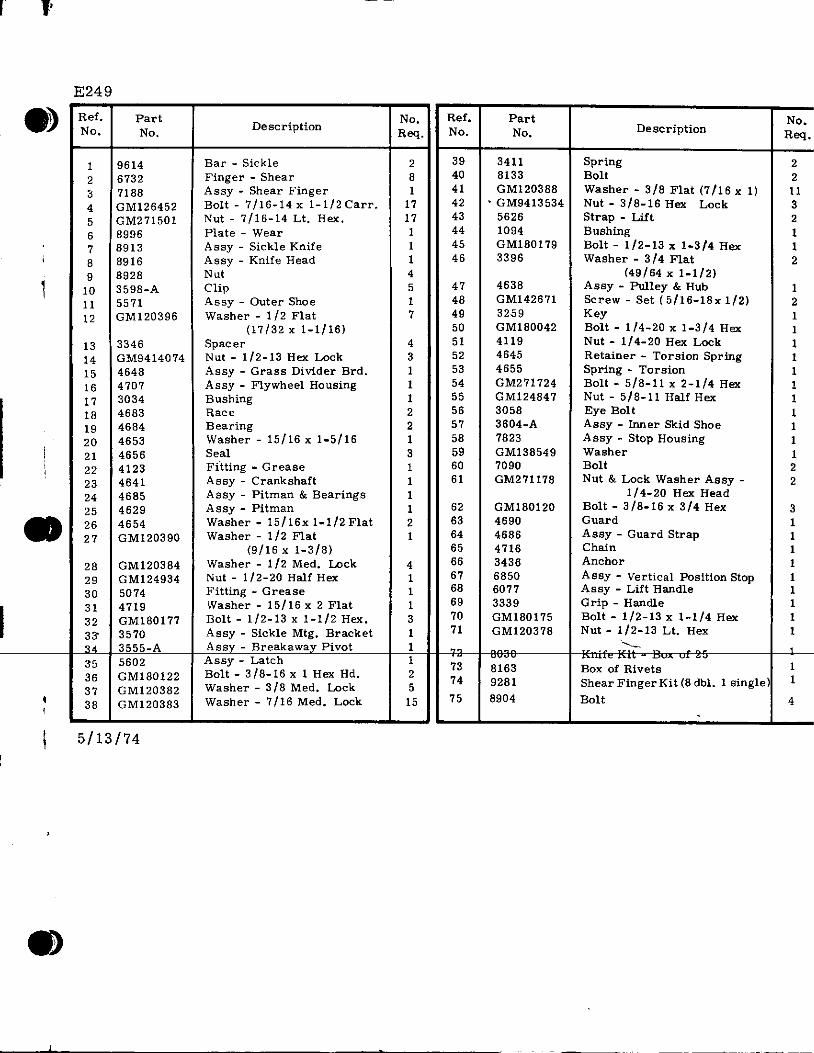
E249a~ Ref. Part ..No. Ref. Part.7 No. No. DescrIption R N N Descri ption No. eq. o. o. Req.
1 9614 Bar -Sickle 2 39 3411 Spring 22 6732 Finger -Shear 8 40 8133 Bolt 23 7188 Assy -Shear Finger 1 41 GM120388 Washer -3/8 Flat (7/16 x 1) 114 GM126452 Bolt -7/16-14 x 1-1/2Carr. 17 42 .GM9413534 Nut -3/8-16 Hex Lock 35 GM271501 Nut -7/16-14 Lt. Hex. 17 43 5626 Strap -Lift 26 8996 Plate -Wear 1 44 1094 Bushing 17 8913 Assy -Sickle Knife 1 45 GM180179 Bolt -1/2-13 x 1-3/4 Hex 1
\ 8 8916 Assy -Knife Head 1 46 3396 Washer -3/4 Flat 29 8928 Nut 4 (49/64 x 1-1/2)
, 10 3598-A Clip 5 47 4638 Assy -Pulley & Hub 111 5571 Assy -Outer Shoe 1 48 GM142671 Screw -Set (5/16-18x 1/2) 212 GM120396 Washer -1/2 Flat 7 49 3259 Key 1
(17/32 x 1-1/16) 50 GM180042 Bolt -1/4-20 x 1-3/4 Hex 113 3346 Spacer 4 51 4119 Nut -1/4-20 Hex Lock 114 GM9414074 Nut -1/2-13 Hex Lock 3 52 4645 Retainer -Torsion Spring 115 4648 Assy -Grass Divider Brd. 1 53 4655 Spring -Torsion 116 4707 Assy -Flywheel Housing 1 54 GM271724 Bolt -5/8-11 x 2-1/4 Hex 117 3034 Bushing 1 55 GM124847 Nut -5/8-11 Half Hex 118 4683 Race 2 56 3058 Eye Bolt 119 4684 Bearing 2 57 3604-A Assy -Inner Skid Shoe 1
I 20 4653 Washer -15/16 x 1-5/16 1 58 7823 Assy -Stop Housing 1I 21 4656 Se.al 3 59 GM138549 Washer 1; 22 4123 Fitting -Grease 1 60 7090 Bolt 2
23 4641 Assy -Crankshaft 1 61 GM271178 Nut & Lock Washer Assy -224 4685 Assy -Pitman & Bearings 1 1/4-20 Hex Head25 4629 Assy -Pitman 1 62 GM180120 Bolt -3/8-16 x 3/4 Hex 3
. 26 4654 Washer -15/16x 1-1/2 Flat 2 63 4690 Guard 127 GM120390 Washer -1/2 Flat 1 64 4686 Assy -Guard Strap 1
(9/16 x 1-3/8) 65 4716 Chain 128 GM120384 Washer -1/2 Med. Lock 4 66 3436 Anchor 129 GM124934 Nut -1/2-20 Half Hex 1 67 6850 Assy -Vertical Position Stop 130 5074 Fitting -Grease 1 68 6077 Assy -Lift Handle 1I31 4719 Washer -15/16 x 2 Flat 1 69 3339 Grip -Handle 132 GM180177 Bolt -1/2-13 x 1-1/2 Hex. 3 70 GM180175 Bolt -1/2-13 x 1-1/4 Hex 133" 3570 Assy -Sickle Mtg. Bracket 1 71 GM120378 Nut -~/2-13 Lt. Hex 134 3555-A Assy -Breakaway Pivot 1 ',---35 5602 Assy -Latch 1 72 8030 Knife Kit -Box of 25 136 GM180122 Bolt -3/8-16 x 1 Hex Hd. 2 73 8163 Box of Rivets 137 GM120382 Washer -3/8 Med. Lock 5 74 9281 ShearFingerKit(8dbl. 1 single) 1
~ 38 GM120383 Washer -7/16 Med. Lock 15 75 8904 Bolt 4
\ 5/13/74i
8)
I. '. _Cc ~--~-~~- --~~--