OPERATOR’S MANUAL - PARTS BOOK SICKLE BAR · PDF filecod. g19503950 2014-01 sickle bar...
72
Cod. G19503950 2014-01 SICKLE BAR MOWER OPERATOR’S MANUAL - PARTS BOOK FIORE MASCHIO GASPARDO S.p.A.
-
Upload
truongdiep -
Category
Documents
-
view
224 -
download
1
Transcript of OPERATOR’S MANUAL - PARTS BOOK SICKLE BAR · PDF filecod. g19503950 2014-01 sickle bar...

Cod. G19503950 2014-01
SICKLE BAR MOWEROPERATOR’S MANUAL - PARTS BOOK
FIORE
MASCHIO GASPARDO S.p.A.

2 cod. G19503950
TABLE OF CONTENTS
3cod. G19503950
OperatingHow to choose between sickle bars ............... 30
Service Machine SafelyPractice safe maintenance ............................. 31Wear appropriate clothing .............................. 31Stay clear of rotating drivelines ...................... 31Maintenance ................................................... 31Hazard bar ...................................................... 32
ServiceLubrifi cation .................................................... 33Routine maintenance...................................... 33Every 2 work hours ......................................... 33Wear-proof skids (optional) ............................ 33Every 8 work hours ......................................... 33Every 50 work hours ....................................... 33Periodically (6 months) ................................... 34After each mowing ......................................... 34Cleaning and oiling the sickle bar .................. 35Storage .......................................................... 35Checking the clearance tolerance .................. 36Extra maintenance.......................................... 38Replacement of section-holding bar ............... 38Replacement of sections ................................ 38Replacement of tooth-holding bar (riveted) .... 39Replacement of tooth (riveted) ....................... 39Replacement of bar holding removable tooth 39Replacement of removable tooth.................... 39Replacing the anti-vibration yokes.................. 40 Replacement of belts ...................................... 40Replacement of pulleys .................................. 40
Transport on roadTransport on road .......................................... 41
Demolition and disposal Demolition and disposal ................................ 42
AssemblyAssembly ........................................................ 43
Spare partsSpare parts ..................................................... 51
WarrantyWarranty ......................................................... 68Warranty for replacement parts ...................... 69
Description Description of the sickle bar mower................. 5Assembly drawing ............................................ 6
Technical specifi cationTechnical specifi cation ...................................... 7Handling ........................................................... 7
Safety lablesSafety-Alert lables ............................................ 8Identifi cation machine ....................................... 8Machine safety labels ....................................... 8
Machine safety lables and positionMachine safety lables and position.................. 9
Preparing the tractorPreparing the tractor ....................................... 10Parking instruction .......................................... 10Stay clear of rotating drivelines ...................... 10
InstallingInstalling sickle bar mower on tractor .......... .. 10PTO shaft adaptation ...................................... 12Stability of sickle bar and tractor during transport ......................................................... 13Parking instruction .......................................... 14Stay clear of rotating drivelines ...................... 14
RemovingRemoving sickle bar mower ........................... 15
OperatingOperate safetly ............................................... 16Wear appropriate clothing .............................. 17Stay clear of rotating drivelines ..................... 17
Operating - Mechanical Lifting SystemUse of Mechanical lifting system .................. 18Adapting the sickle bar mower ....................... 18Adjustment ..................................................... 18Mowing ........................................................... 20
Operating - Hydraulic Lifting SystemUse of Hydraulic lifting system ...................... 22Adapting the sickle bar mower ....................... 24Adjustment...................................................... 25Using the lifting device.................................... 26Operation of lifting device ............................... 26Mowing on fl at ground .................................... 27Mowing on slopes ........................................... 28
Operating - Quick CouplerQuick Coupler ................................................. 29Removing sickle bar mower withQuick Coupler ................................................. 29

4 cod. G19503950
TO THE DEALER:Assembly and proper installation of this product is the responsibility of the MASCHIO GASPARDO dealer. Read manual instruction and safety rules. Make sure all items on the Dealer’s Pre-Delivery Check List in the Operator’s Manual are completed before releasing equipment to the owner.
The dealer must complete the Warranty Registration, located on the MASCHIO GASPARDO website. Warranty claims will be denied if the Warranty Registration has not been completed.
TO THE OWNER:Read this manual before operating your frontier equipment. The information presented will prepare you to do a better and a safer job. Keep this manual handy for ready reference. Require all operators to read this manual carefully and become acquainted with all the adjustment and operating procedures before attempting to operate. Replacement manuals can be obtained from your selling dealer.
The equipment you have purchased has been carefully enginereed and manufactured to provide dependable and satisfactory use. Like all mechanical products, it will require cleaning and upkeep. Lubricate the unit as specifi ed. Observe all safety information in this manual and safety decals on the equipment.
For service, your authorized MASCHIO GASPARDO dealer has trained mechanics, genuine MASCHIO GASPARDO service parts, and the necessary tools and equipment to handle all your needs.
Use only genuine MASCHIO GASPARDO service parts. Substitute parts will void the warranty and may not meet standards required for safe and satisfactory operation. Record the model number and serial number of your equipment in the spaces provided:
Model: _________________________________ Date of Purchase _____________________________
Serial Number: (see Safety Decal section for location) _______________________________________
Provide this information to your dealer to obtain correct repair parts.
Throghout this manual, the term IMPORTANT is used to indicate that failure to observe can cause damage to equipment. The terms CAUTION, WARNING and DANGER are used in conjunction with the Safety-Alert Symbol, (a triangle with an esclamation mark), to indicate the degree of hazard for items of personal safety.
This Safety-Alert Simbol indicates a hazard and means AT-TENTION! BECOME ALERT! YOUR SAFETY IS INVOLVED!
Indicates an imminently hazardous situation that, if not avoi-ded, will result in death or serious injury.
Indicates a potentially hazardous situation that, if not avoided, could result in death or serious injury, and includes hazards that are exposed when guards are removed.
Indicates a potentially hazardous situation that, if not avoided, may result in minor or moderate injury.
Indicates that a failure to observe can cause damage to equipment.
Indicates helpful information.
WARNING
CAUTION
IMPORTANT
NOTE
DANGER.
DESCRIPTION
5cod. G19503950
Fig. 1
Fig. 3
Fig. 2
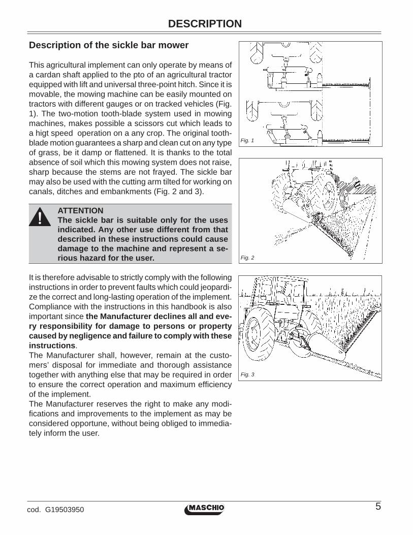
Description of the sickle bar mower
This agricultural implement can only operate by means of a cardan shaft applied to the pto of an agricultural tractor equipped with lift and universal three-point hitch. Since it is movable, the mowing machine can be easily mounted on tractors with different gauges or on tracked vehicles (Fig. 1). The two-motion tooth-blade system used in mowing machines, makes possible a scissors cut which leads to a higt speed operation on a any crop. The original tooth-blade motion guarantees a sharp and clean cut on any type of grass, be it damp or fl attened. It is thanks to the total absence of soil which this mowing system does not raise, sharp because the stems are not frayed. The sickle bar may also be used with the cutting arm tilted for working on canals, ditches and embankments (Fig. 2 and 3).
ATTENTIONThe sickle bar is suitable only for the uses indicated. Any other use different from that described in these instructions could cause damage to the machine and represent a se-rious hazard for the user.
It is therefore advisable to strictly comply with the following instructions in order to prevent faults which could jeopardi-ze the correct and long-lasting operation of the implement. Compliance with the instructions in this handbook is also important since the Manufacturer declines all and eve-ry responsibility for damage to persons or property caused by negligence and failure to comply with these instructions. The Manufacturer shall, however, remain at the custo-mers’ disposal for immediate and thorough assistance together with anything else that may be required in order to ensure the correct operation and maximum effi ciency of the implement. The Manufacturer reserves the right to make any modi-fi cations and improvements to the implement as may be considered opportune, without being obliged to immedia-tely inform the user.

DESCRIPTION
6 cod. G19503950
1
6
8
11
14
9
Assembly drawing
1 External shoe;2 Mowing guide;3 Cutting arm;4 Upper 3rd point hitches;5 Gauge varying articulation;6 Chassis;7 Tirant;8 Lower 3rd point hitches;9 Hazard bar;10 Support;11 Identifi cation label;12 Cover;13 Protective casing for connecting-rod systems;14 Support;15 Hinge (pivot point);16 Blade guard;17 PTO;18 Lift link adjuster chain;19 Hoisting arm.
Fig. 4
13
16
15
17
2
3
4
5
1012
7
19
13
18

TECHNICAL SPECIFICATIONS
7cod. G19503950
L
Model
Belts1.75 68.9 25 - 50 507
B-93540 110.7 dB 91.7 dB
2.35 92.5 543
Tractor
HP
min. - max.
25 - 50
Work
speed
miles/h
Work/width
inches
L
Weight
lbs.
Side
DrivePTO
Input
speed
Hitch Acoustic power level
uttered bay machine
(Weighed A) LWA
Continuous equivalent acoustic
radiation pressure level (Weighed
A) in the "worker's position" LpA
12
16
Tooth
number
24
32
2.05 80.7 52525 - 50 14 28
Sections
number
6.2 7.5
FBR Plus
Fig. 5
HandlingDuring handling operations, use suitable personal protection devices:
If the machine is handled, it must be lifted by hooking (Fig. 5) onto the appropriate holes with a suitable winch or crane of suffi cient capacity. Because of the danger involved, this operation should be carried out by trained and responsible personnel. The mass of the machine is on the identifi cation label (11, Fig. 4).Stretch the rope to keep the machine level.The lifting points can be detected by fi nding the symbol (8 page 9).During handling operations make sure the implement has the required safety devices and guards.

SAFETY LABLES
8 cod. G19503950
Safety-alert lablesRead and recognize safety information.Be alert to the potential for personal injury when you see this safety-alert lables.
On your machine safety labels, the words DANGER, WARNING, and CAUTION are used with a safety symbols. DANGER identifi es the most serious hazards. In this manual, the word CAUTION and this symbol call attention to safety messages.
Identifi cation machineIdentifi cation label
Machine safety labels
1) CAUTION: AVOID INJURY • Read Operator’s Manual • Ballast power unit per operator’s manual • Know location and function of controls • Keep all shields in place • Stay clear of power driven parts • Never carry riders • Keep people and pets a safe distance away from machine BEFORE DISMOUNTING OR SERVICING • Shut off engine and remove key • Lock brake for park • Lower or block up machine
2) CAUTION 1 Keep all shields in place. 2 Disengage and shut off all engine and/or motor power before servicing or unclogging machine. 3 Keep hands, feet and clothing away from power-driven parts.
3) DANGER: CRUSHING AND PINCH POINTS MOVING MACHINERY PARTS CAN: 1° PINCH OR CRUSH OR FALL 2° WHICH MAY CAUSE INJURY OR DEATH.
4) DANGER Entanglement in rotating driveline can cause serious injury or death. Keep all shields in place. Avoid contact with rotating parts.
5) DANGER: KEEP AWAY - SHARP BLADES • Do not put hands or feet near the cutterbar. Blade contact can result in serious injury. • Stay away until all motion has stopped and the mower is securely blocked up. • Keep fi ngers clear of cutterbar when folding cutterbar for transport.
6) CAUTION Operate only with 540 rpm PTO.

MACHINE SAFETY LABELS AND POSITION
9cod. G19503950
E n t a n g l e m e n t i n r o t a t i n g driveline can cause serious injury or death.
Keep all shields in place.
Avoid contact with rotating parts.
4
CRUSHING AND PINCH POINTSMOVING MACHINERY PARTS CAN
PINCH OR CRUSH OR FALL -
WHICH MAY CAUSE INJURY OR DEATH.
3
1. Keep all shields in place.
2. Disengage and shut off all engine
and/or motor power before
servicing or unclogging machine.
3. Keep hands, feet and clothing
away from power-driven parts.
2
KEEP AWAYSHARP BLADES
- Do not put hands or feet near the cutterbar. Blade contact can result in serious injury.
- Stay away until all motion has stopped and the mower is securely blocked up.
- Keep fingers clear of cutterbar when folding cutterbar for transport.
5
6
8
9
1
7
9
5
8
Operate only with
540 rpm PTO
1 2 3 4
34
6
7
7) High noise level. Use adequate acoustic protection.8) Coupling point for lifting.9) Greasing point.

PREPARING THE TRACTOR
10 cod. G19503950
Preparing the tractor
CAUTION: Avoid injury. Proper ballastings is required for safe operation of your sickle bar mower
IMPORTANT: Refer to the tractor operator manual for proper ballasting information and tire infl ation
• A 540 rpm PTO• Refer to the tractor operator manual for correct ballasting and tire pressure, depending on installed
equipment.
Parking instruction• Stop vehicle on a lever surface, not on a slope.• Disengage PTO.• Engage the park brake.• STOP the engine.• Remove the key.• Before you leave the operator’s seat, wait for engine and all moving parts to STOP.
Stay clear of rotating drivelinesEntanglement in rotating driveline can cause serious injury or death:• Wear close fi tting clothing.• STOP the engine and be sure PTO driveline is stopped
before getting near it.
Installing sickle bar on tactorThe sickle bar can be hitched to I, II or quick coupler cate-gory tractor equipped with a universal three-point coupling.
DANGER Application of any implement to a tractor is
a very dangerous operation and must only be carried out with the utmost care in com-pliance with the instructions.
The correct tractor/sickle bar position is established by setting the implement at such a distance from the tractor that the universal coupling remains 2-4 inches from its ma-ximum closing position. Now proceed in the following way:
1. Back tractor into position and align draft links (A, Fig. 6) with draft link brackets on sickle bar.
CAUTION: Before you work around hitch: • STOP engine. • LOCK park brake. • FIRMLY block mower on horizontal surface.
2. Connect the upper third-point and correctly regulate by means of the adjuster (B, Fig. 7). Place plate (C, Fig. 7) at the left side of the hicht integral with the same pin. Lock in place with the snap-in split pins (D, Fig. 8).
E
FC
B
Fig. 7
I
Fig. 6A

INSTALLING
11cod. G19503950
ML
D
Fig. 9
G
Fig. 8
H
M1
O
P
N
Fig. 10
3. Hook the oscillating arms of the tractor to pins (E and F, Fig. 7). The hoisting arm (H, Fig. 8) must be fi xed un-derneath the tractor arm. Lock in place with the snap-in split pins (G Fig. 8)
4. Lock the lift links using the relative chains (I, Fig. 7)
and couplings parallel to the tractor. This operation must be carried out to prevent the machine from moving in a horizzontal direction.
5. Install PTO shaft to tractor (Fig. 9).
IMPORTANT: Sickle bar mower MUST BE level front to rear.
Make sure PTO shaft is locked on the tractor PTO prior to engagement (L). Check that the guard (M) is free to turn and fi x it with the relative latch (M1).
6. Remove the guard over the cutters (16, Fig. 4) and remove the tirant (7, Fig.4).
7. Lift-up sickle bar.
8. Remove spring locking pin (N, Fig. 10) from parking stand.
9. Remove support (O and P, Fig. 10) and remount them, upside-down in their seat .
10. Fasten with spring locking pin (N, Fig. 10).
INSTALLING
12 cod. G19503950
min. 6 inches
min. 137/64 inches
Max
Min
S
Fig. 13
Fig. 11
Q
R
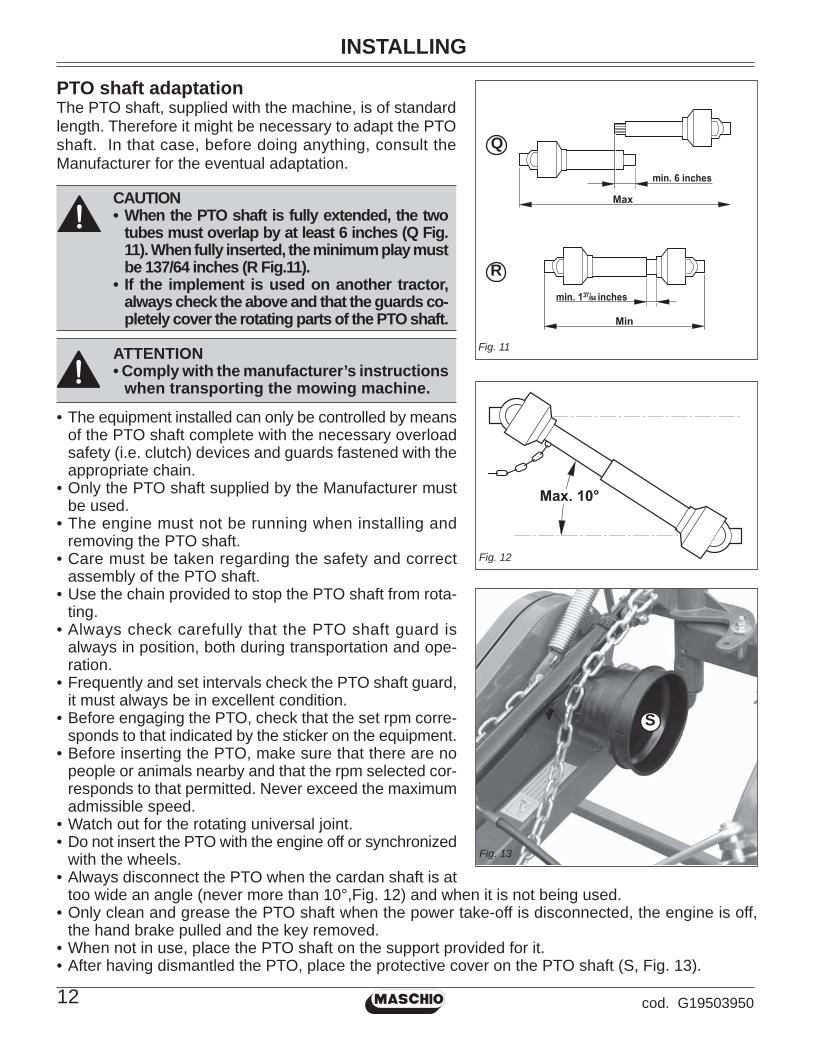
PTO shaft adaptationThe PTO shaft, supplied with the machine, is of standard length. Therefore it might be necessary to adapt the PTO shaft. In that case, before doing anything, consult the Manufacturer for the eventual adaptation.
CAUTION• When the PTO shaft is fully extended, the two
tubes must overlap by at least 6 inches (Q Fig. 11). When fully inserted, the minimum play must be 137/64 inches (R Fig.11).
• If the implement is used on another tractor, always check the above and that the guards co-pletely cover the rotating parts of the PTO shaft.
ATTENTION• Comply with the manufacturer’s instructions
when transporting the mowing machine.
• The equipment installed can only be controlled by means of the PTO shaft complete with the necessary overload safety (i.e. clutch) devices and guards fastened with the appropriate chain.
• Only the PTO shaft supplied by the Manufacturer must be used.
• The engine must not be running when installing and removing the PTO shaft.
• Care must be taken regarding the safety and correct assembly of the PTO shaft.
• Use the chain provided to stop the PTO shaft from rota-ting.
• Always check carefully that the PTO shaft guard is always in position, both during transportation and ope-ration.
• Frequently and set intervals check the PTO shaft guard, it must always be in excellent condition.
• Before engaging the PTO, check that the set rpm corre-sponds to that indicated by the sticker on the equipment.
• Before inserting the PTO, make sure that there are no people or animals nearby and that the rpm selected cor-responds to that permitted. Never exceed the maximum admissible speed.
• Watch out for the rotating universal joint.• Do not insert the PTO with the engine off or synchronized
with the wheels.• Always disconnect the PTO when the cardan shaft is at
too wide an angle (never more than 10°,Fig. 12) and when it is not being used.• Only clean and grease the PTO shaft when the power take-off is disconnected, the engine is off,
the hand brake pulled and the key removed.• When not in use, place the PTO shaft on the support provided for it.• After having dismantled the PTO, place the protective cover on the PTO shaft (S, Fig. 13).
Fig. 12

INSTALLING
13cod. G19503950
Stability of sickle bar mower and tractor during transport
When a sickle bar is coupled to a tractor, so becoming an integral part of it for the purposes of road travel, the stability of the sickle bar-tractor complex may change and cause driving or operating dif-fi culties (rearing up or side-slipping of the tractor). The condition of equilibrium can be restored by placing a suffi cient number of ballasts on the front of the tractor so that the weights on the two tractor axles are distributed suffi ciently evenly. To work in safety the instructions given in the highway code should be followed; these prescribe that at least 20% of the weight of the tractor alone should be borne by the front axle and that the weight on the arms of the hoist should not be more than 30% of the weight of the tractor itself. These factors are summarized in the following formulas:
Z > (M x s)-(0.2 x T x i) (d+i)The amount of ballast that should be applied according to the formula is the minimum required for circulation on the road. If for reasons of tractor performance or to improve the set-up of the sickle bar during operation it is thought necessary to raise these values, please refer to the registration document of the tractor to check its limits. When the formula for calculating the ballast gives a negative result it will not be necessary to add any weight. In any case, as long as the limits of the tractor are respected, a suitable quantity of weights may be applied in order to ensure greater stability during travel. The symbols have the following meanings:
(please see Fig. 14 for reference):
M KgMass weighing on arms off hoist with full load
(Technical data table)
T Kg Mass of tractor
Z Kg Total mass of ballast
i mTractor wheelbase, that is, the horizontal
distance between the tractor axles
d mHorizontal distance between the centre of gravity
of the ballast and the front axle of the tractor
s mHorizontal distance between the centre of gravity ofthe operating machine and the back axle of the tractor
169/64
inches
Fig. 14

INSTALLING
14 cod. G19503950
Parking instructions• Stop vehicle on a level surface, not on a slope.• Disengage PTO.• Engage the park brake.• STOP the engine.• Remove the key.• Before you leave the operator’s seat, wait for engine and all moving parts to STOP.
Stay clear of rotating drivelinesEntanglement in rotating driveline can cause serious injury or death:• Wear close fi tting clothing.• STOP the engine and be sure PTO driveline is stopped before getting near it.

REMOVING
15cod. G19503950
CAUTION: Before you work around hitch:• STOP engine.• LOCK park brake.• FIRMLY block mower on horizontal surface.
H
D
E
I
F
J
G
Fig. 16
Fig. 17
B
AC
Fig. 15
Removing sickle bar mower
The sickle bar must be set-up on fl at and compact ground, supported by the relative supports (A and B, Fig. 15).
1. Raise sickle bar.2. Put parking stand (A and B, Fig. 15) in the DOWN
position: install spring locking pin in order to secure parking stand (C, Fig. 15).
3. Lower sickle bar to the ground.
4. Unhook the PTO schaft (, Fig. 16) from the tractor and put in on the special hook.
5. Remove quik-lock pin (D, Fig. 17) and pin (E, Fig. 17) from center link (F, Fig. 17).
NOTE: Put quik-lock pins and pins back into brackets on sickle bar for storage.
6. Remove draft links (J, Fig. 17) from draft link brackets (G, Fig. 17) by removing quiklock pins (H, Fig. 17) and pins (I, Fig. 17).
NOTE: Put quik-lock pins and pins back into brackets on sickle bar for storage.
7. Drive tractor forward slowly.

OPERATING
16 cod. G19503950
Operate safetly
Carefully read all the instructions before using the machine; if in doubt, contact the techni-cians of the Manufacturer’s dealer. The manufacturer declines all responsibility for the non-observance of the safety and accident prevention regulations described below.
General norms1) Pay close attention to the danger signs in this manual and on the sickle bar.2) The labels with the instructions attached to the machine give abbreviated advice for avoiding
accidents.3) Carefully observe, with the help of the instructions, the safety and accident prevention regulations.4) Avoid touching moving parts in any way whatsoever.5) Any work on and adjustment to the machine must always be done with the engine switched off
and the tractor blocked.6) People or animals must not, under any circumstances, be transported on the equipment.7) It is strictly prohibited to drive the tractor, or allow it to be driven or with the equipment attached
by persons not in possession of a driver’s license, an expert or in poor conditions of health.8) Before starting the tractor and the equipment, check that all safety devices for transport and use
are in perfect working order.9) Before starting up the equipment, check the area surrounding the machine to ensure that there
are no people, especially children or pets, nearby, and ensure that you have excellent visibility.10) Use suitable clothing. Avoid loose clothing or garments with parts that could in any way get caught
in the rotating or moving parts of the machine.11) Before starting work, familiarize yourself with the control devices and their functions.12) Only start working with the equipment if all the protective devices are in perfect condition, installed
and in the safe position.13) It is absolutely prohibited to stand within the machine’s radius of action where there are moving
parts.14) It is absolutely forbidden to use the equipment without the guards.15) Before leaving the tractor, lower the implement coupled to the lift unit, stop the engine, engage the
hand brake, remove the ignition key from the control panel, cover the cutters and outer skid with the relative guards. Raise the mowing bar (transport protection) according with the instructions given in this handbook.
16) The driver’s seat must never be left when the tractor engine is running.17) Before operating the mowing machine, check that the support struts (A and B, Fig. 15 page 15)
have been removed from underneath the implement. Make sure that the sickle bar has been cor-rectly mounted and adjusted. Check that the machine is in perfect order and that all components subject to wear and deterioration are effi cient.
18) Before releasing the equipment from the third point attachment, put the hoist command lever into the locked position and lower the support feet.
19) Only operate during daylight or with proper artifi cial light.20) All operations must be carried out by expert personnel, equipped with protective gloves, in a clean
and dust-free environment.21) Do not climb onto the machine while it is running, even if it is stationary.22) Before approaching the mowing bar, disengage the pto, switch off the tractor, engage the parking
brake and check that the cutters are at a complete standstill.23) The coupled implement may only be controlled through the PTO shaft complete with the necessary
safety devices for overloads and with the guards fi xed with the relative latch.24) During maintenance and work operations, make sure that no other person goes near the tractor
and the implement and accidentally works the controls with the risk of causing injury to persons and damage to property.
25) As a precaution, always set adeguate supports under the implement during assembly, servicing, cleaning or assembly work with the mowing bar raised.

OPERATING
17cod. G19503950
26) DO NOT wear radio or music headphones while operating the machine. Safe operation requires your full attention.
27) DO NOT operate the tractor and sickle bar when you are tired or ill.
Tractor hitch1) Hook the equipment to a suitable, suffi ciently-powered tractor by means of the appropriate device
(lifter), in conformity with applicable standards.2) The class of the equipment attachment pins must be
the same as that of the lifter attachment.3) Take care when working within the range of the lifting
arms as this is a very dangerous area.4) Be very careful when hooking and unhooking the
equipment.
5) It is absolutely forbidden to stand between the tractor and linkage for acting the lifting controls from the outside (Fig. 18).
6) It is absolutely forbidden to stand in the space between the tractor and the equipment (Fig. 18) with the engine running.
7) The attaching of additional equipment onto the tractor brings about a different distribution of weight on the axles. Check the compatibility of the tractor performance with the weight that the mower transfers onto the three-point linkage. If in doubt consult the tractor Manufacturer.
8) Comply with the maximum admissible weight for the axle, the total mobile weight, transport regu-lations and the highway code.
Wear appropriate clothing• Wear close fi tting clothing and safely equipment appropriate for the job.• Loud noise can cause impairment or loss of hearing, wear a suitable pro-
tective device such as earplugs.
Stay clear of rotating drivelinesEntanglement in rotating driveline can cause serious injury or death:• Wear close fi tting clothing• Stop the engine and be sure PTO shaft is stopped before getting near it.
CAUTION: Before you work around hitch:• STOP engine.• LOCK park brake.• FIRMLY block mower on horizontal surface.
Fig. 18

OPERATING - MECHANICAL LIFTING SYSTEM
18 cod. G19503950Fig. 23
(1 ) (2) (3)
Fig. 20 Fig. 21
Fig. 19
D
EFig. 22
Use of MECHANICAL lifting system (Fig. 19)
Adapting the sickle bar mowerTo ensure optium use, the sickle bar must completely project from the tractor (Fig. 20); three situations are shown in the Figure 21: 1) hitching to a tractor normally used for mowing jobs;2) hitching to a large tractor;3) hitching to a small tractor or to certain types of tracked
vehicle.
AdjustmentBefore starting a mowing session, adjust the machine so that the best working setup is obtained. Correct machine setup guarantees excellent mowing, allows for the best machine-tractor performance and remarkably reduces wear of the cutting blades.
• Remove safety hook (D, Fig. 22), required only for transportation, and fi t it back in the slot positioned above the chassis.
• Fit the sickle bar by adjusting the tractor tie-rods so that, when the sickle bar attachment is fi tted to the three points on the tractor, the external tip of the cutting arm is approximately 2 inches. foward with respect to the arm base (Fig. 23).

OPERATING - MECHANICAL LIFTING SYSTEM
19cod. G19503950
• Connect one end of the chain (F, Fig. 24) to the mower using the supplied pin and the other end to a stationary point on the tractor. Adjust the height of the mower to the ground (19.6 to 21.7 inches, Fig. 24) by moving the rings of the chain (F, Fig. 24) in the hole on the plate (G, Fig. 24). When the lifter is lowered, this precaution will constantly hold the mower at the same height from ground level.
• Act on the tie rod-spring (K, Fig. 24) to bring the internal skid close to the ground (without dischar-ging the weight on the ground), lightening the load of the machine on the cutter bar.
• Adjusting the hoisting chain (H, Fig. 25) so that during mowing the hoisting arm (I, Fig. 25) is free to move up and down; in this way, the cutting arm can follow any unevenness of the ground.
So that the mower will work well, we advise you to fi x the chain (H Fig. 25) to the lifting arm (I Fig. 25) at the level of the 7th or 8th link of the chain.
• Adjust the heigt of the cutting arm from the ground with chain (J, Fig. 26). Lower the mower; when the external tip of the arm touches the ground, the inner shoe must remain approximately 10 cm. above ground level (Fig. 26). Adjust by moving the chain links.
So that the mower will work well, we advise you to fi x the chain (J, Fig. 25-26) to the equalizer (L, Fig. 25-26), leaving the last links of the chain free.
• Adjust inclination of the cutting arm teeth using tie rod (M, Fig. 27).
For low, moist and thick fodder, tilt the teeth downwards by shortening the tie rod (M, Fig. 27).
For ground with rocks and stones tilt the teeth upwards by lengthening the tie rod (M, Fig. 27).
• Adjust the cutting height (Fig. 28) by moving the mowing bar on the holes of the inner mowing bar support (N), and, turning the nut of the outer mowing bar support (M), bring it level with the ground.
Min. 1,2 inchesMax. 2,7 inches
O
Fig. 28
Fig. 26
Fig. 25
I
1°
7°/8°
MFig. 27
19.6
÷ 2
1.7
inch
es
F
Fig. 24G
K
J
N
L
H

OPERATING - MECHANICAL LIFTING SYSTEM
20 cod. G19503950
Mowing
• Remove the supports (P and Q, Fig. 29) and remount them, upside-down in their seat . Install spring locking pin in order to secure parking stand (R).
TU
• Remove tie rod (S, Fig. 30) from the cutting arm.• Remove safety hook (D, Fig. 22), required only for tran-
sportation, and fi t it back in the slot positioned above the chassis.
• The sickle bar is fi tted with a safety device for protection against obstacles. If this device is tripped by impact with an obstacle, stop the tractor without raising the cutting arm. Check that the cardan shaft has not become se-perated, if so, reassemble it. Position the safety tie rod parallel to the ground, and reverse the tractor until the safety tie rod hooks up again. If the tie rod releases easly, adjust spring (T, Fig. 31) using nut (U, Fig. 31) which should be tightened half turn at a time.
ATTENTIONA spring compression other than that indicated in Figure 31 (0.59 inches) can make the safety device ineffective.
For successful mowing and to avoid jamming, we advise you to:• Set and maintain the power take-off at a constant
rate of 540 rpm to ensure correct blade frequency; maintain an engine speed of 1800÷2000 rpm.
• compatibly with the soil conditions and the type of grass, maintain a steady work speed: no slower than 5 mph to favor the discharging of the mown grass and no faster than 6.2 mph to avoid breaking or damaging the machi-ne’s structure.
• if the grass is tangled or fl attened, keep the cutting bar grazing the ground.
Fig. 31
Fig. 30
Q
P
R
Fig. 29
S
0.59 i
nches
(15 m
m)

OPERATING - MECHANICAL LIFTING SYSTEM
21cod. G19503950
ATTENTIONIf the blades becomes jammed, it is advisable to operate carefully wearing suitable personal protection. All the maintenance, adjustments and work preparation operations, must be carried out with the tractor strictly switched off and properly stationary, with the ignition key turned off and the sickle bar on the ground.
CAUTION• Always raise the implement in order to reverse or change direction.• The cutting arm should not be raised abruptly in order to avoid damaging the cutting blades.• Power take-off must not exceed 540 r.p.m.• Never run the engine at maximum power while mowing.• In order to prevent breakages or damage, the speed of the tractor must never exceed 6.2 mph
when the implement is working.
DANGERThe mowing machine has sharp cutting blades. Always make sure that there are no persons, domestic animals, electrical cables, pipes and so forth, within the fi eld of action of the implement.

OPERATING - HYDRAULIC LIFTING SYSTEM
22 cod. G19503950
Use of HYDRAULIC lifting system (Fig. 32)
To install the hydraulic lifting kit of the mower, on versions with mechanical lifting, it is necessary to remove some parts of the equipment. Some pieces to be detached from the equipment are indicated on page 23 (ref. 1).Install the Kit following the in-structions given on page 23 (ref. 2 to 11).
Fig. 32

OPERATING - HYDRAULIC LIFTING SYSTEM
23cod. G19503950
3
6 8
M16 x 70
M8 x 25
1 2
4
M12 x 45
5 M8 x 25
7
9 1110

OPERATING - HYDRAULIC LIFTING SYSTEM
24 cod. G19503950
Adapting the sickle bar mower
To ensure optium use, the sickle bar must completely project from the tractor (Fig. 33); three situations are shown in the Figure 34:
1) hitching to a tractor normally used for mowing jobs;2) hitching to a large tractor;3) hitching to a small tractor or to certain types of tra-
cked vehicle.
(1 ) (2) (3)
Fig. 34
Fig. 35
C
B A
Fig. 36A1 A2 A3
C1C2 C3
B
Fig. 33
When the frame joint is moved (A, Fig. 35), the position of the stop bushing (C, Fig. 35) of the cylinder linkage must consequently be changed, according to the cases shown in fi gures 35 and 36.
Connections between frame joint and stop bushing for the movement of the mowing bar.

OPERATING - HYDRAULIC LIFTING SYSTEM
25cod. G19503950
M
Fig. 38
Fig. 40
Fig. 41
Adjustment
Before starting a mowing session, adjust the machine so that the best working setup is obtained. Correct machine setup guarantees excellent mowing, allows for the best machine-tractor performance and remarkably reduces wear of the cutting blades.
• Remove safety hook (D, Fig. 37), required only for tran-sportation, and fi t it back in the slot positioned above the chassis.
• Fit the sickle bar by adjusting the tractor tie-rods so that, when the sickle bar attachment is fi tted to the three points on the tractor, the external tip of the cutting arm is approximately 2 inches. foward with respect to the arm base (Fig. 38).
• Connect one end of the chain (F, Fig. 39) to the mower using the supplied pin and the other end to a stationary point on the tractor. Adjust the height of the mower to the ground (19.6 to 21.7 inches, Fig. 39) by moving the rings of the chain (F, Fig. 39) in the hole on the plate (G, Fig. 39).
When the lifter is lowered, this precaution will constantly hold the mower at the same height from ground level.
• Act on the tie rod-spring (K, Fig. 39) to bring the internal skid close to the ground (without discharging the weight on the ground), lightening the load of the machine on the cutter bar.
• Adjust inclination of the cutting arm teeth using tie rod (M, Fig. 40).
for low, moist and thick fodder, tilt the teeth downwards by shortening the tie rod (M, Fig. 40).
for ground with rocks and stones tilt the teeth upwards by lengthening the tie rod (M, Fig. 40).
• Adjust the cutting height (Fig. 41) by moving the mowing bar on the holes of the inner mowing bar support (N), and, turning the nut of the outer mowing bar support (O), bring it level with the ground.
D
EFig. 37
Fig. 39
19.6
÷ 2
1.7
inch
es
FGK
Min. 1,2 inchesMax. 2,7 inches
ON

OPERATING - HYDRAULIC LIFTING SYSTEM
26 cod. G19503950
Using the lifting device
Once you have positioned the equipment, prepare it for mowing:• release the blade tie rod;• remove the support prop;• remove the blade protection.
Operation of lifting device
Put the rope (S, Fig. 42) for releasing the bracket (T, Fig. 42) inside the tractor cabin.
Climb into the tractor and operate the hydraulic distributor to lower the blade (Fig. 43) into the mowing position.
CAUTION: While working regularly check that the bracket (T) is still resting along the cylinder rod (Fig. 44).
Fig. 42
Fig. 43
Fig. 44
S
T
T
T
Fig. 45
S
Raising of the cutter bar for road transport
• Fit the guards over the cutters and outer skid (C Fig. 60.
• From the tractor, pull the rope (S, Fig. 45) to disable the bracket (T, Fig. 45) and operate the hydraulic distributor to fully raise the cutter bar.
• Sicure it with the hooking tie rod.

OPERATING - HYDRAULIC LIFTING SYSTEM
27cod. G19503950
Mowing on fl at ground (or ground with small depressions)
For mowing operations on level ground, couple the lever mechanisms (V and Z, Fig. 46) in posi-tion (X, Fig. 46). Lastly insert the lifting device as described in the previous paragraph.
With the rapid lifting device engaged, the bar (U, Fig. 47) has a negative inclination of -15° with respect to the horizontal plane during mowing, and a positive inclination that varies according to the lie of the land.This system has been devised for mowing quickly and safely on fl at ground or ground with small depressions.
The operation of the lifting device up to the stop of the bracket on the cylinder (T, Fig. 48) allows the equipment to be raised by approx. 12.5 inches from the ground and, at the same time, an incli-nation of the blade (U, Fig. 48) of + 25°, so that the end of fi eld maneuvers can be carried out.
25°
19.6
÷ 2
1.7
inch
es
12.5
inch
es
U
-15°
19.6
÷ 2
1.7
inch
es
Z
X
V
U
Fig. 48
T
Fig. 46
Fig. 47

OPERATING - HYDRAULIC LIFTING SYSTEM
28 cod. G19503950
Mowing on slopes
Figure 49 show type of mowing on sloping ground (banks, canals, etc.).
CAUTION: For mowing on surfaces that are not parallel to the tractor plane, we recommend removing the moving guide from the outer mowing bar support.To mount pulling of Figure 50 in or-der to improve the excursion and use of the sickle bar.
Only for mowing on sloping ground, it is necessary to prepare the machine according to the instruc-tions given below:
1) Move the lever mechanisms (V and Z, Fig. 51) to position (Y).
2) Lift the bracket (T) as shown in Figure 51, and lock it with the rod (W) in the lower position of the slot (ref. W1, Fig. 51).
3) To avoid unpleasant problems during move-ment of the cutter bar, detach the steel cable (S) from the rod (W) and retrieve it up to posi-tion (S1) .
In this way the bar can be adjusted with the hydraulic cylinder to mow at different angles: from -45° to +90° with respect to the horizontal plane formed by the tractor (Fig. 52).
IMPORTANT:The sickle bar can operates in each position between -45° to +90°.
Fig. 49
Fig. 50
SS1
+90+90
-45-45
Fig. 52
Fig. 51
W
T
Z
Y
V
W1
OPERATING - QUICK COUPLER
29cod. G19503950
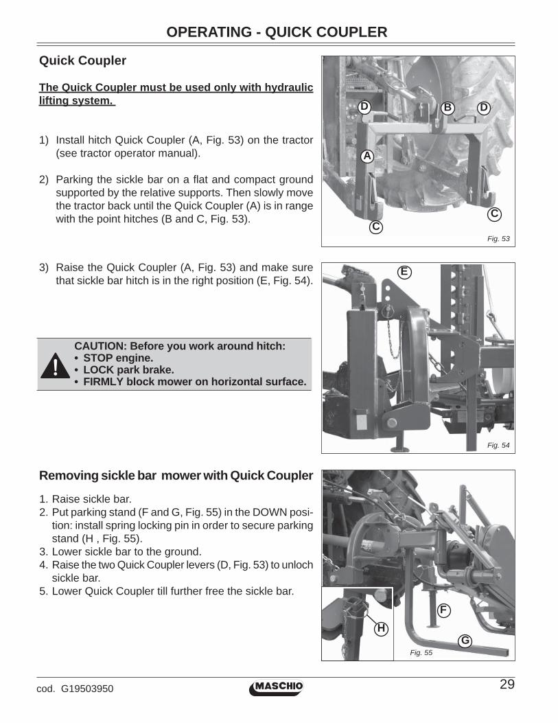
Quick Coupler
The Quick Coupler must be used only with hydraulic lifting system.
1) Install hitch Quick Coupler (A, Fig. 53) on the tractor (see tractor operator manual).
2) Parking the sickle bar on a fl at and compact ground supported by the relative supports. Then slowly move the tractor back until the Quick Coupler (A) is in range with the point hitches (B and C, Fig. 53).
CAUTION: Before you work around hitch:• STOP engine.• LOCK park brake.• FIRMLY block mower on horizontal surface.
3) Raise the Quick Coupler (A, Fig. 53) and make sure that sickle bar hitch is in the right position (E, Fig. 54).
A
D DB
CC
E
Fig. 53
Fig. 54
Removing sickle bar mower with Quick Coupler
1. Raise sickle bar.2. Put parking stand (F and G, Fig. 55) in the DOWN posi-
tion: install spring locking pin in order to secure parking stand (H , Fig. 55).
3. Lower sickle bar to the ground.4. Raise the two Quick Coupler levers (D, Fig. 53) to unloch
sickle bar.5. Lower Quick Coupler till further free the sickle bar.
G
F
Fig. 55
H
OPERATING
30 cod. G19503950
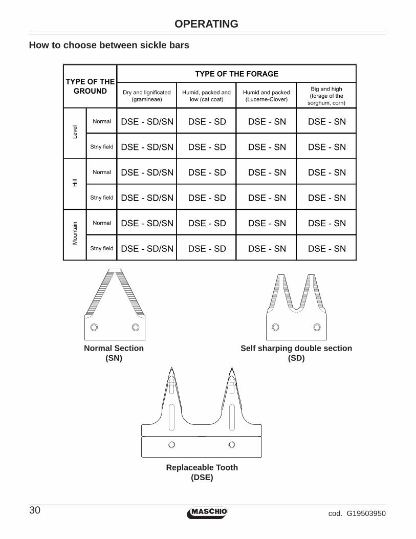
How to choose between sickle bars
Dry and lignificated (gramineae)
Humid, packed and low (cat coat)
Humid and packed (Lucerne-Clover)
Big and high (forage of the
sorghum, corn)
Normal DSE - SD/SN DSE - SD DSE - SN DSE - SN
Stny field DSE - SD/SN DSE - SD DSE - SN DSE - SN
Normal DSE - SD/SN DSE - SD DSE - SN DSE - SN
Stny field DSE - SD/SN DSE - SD DSE - SN DSE - SN
Normal DSE - SD/SN DSE - SD DSE - SN DSE - SN
Stny field DSE - SD/SN DSE - SD DSE - SN DSE - SN
Mou
ntai
nTYPE OF THE
GROUND
TYPE OF THE FORAGELe
vel
Hill
Normal Section(SN)
Self sharping double section(SD)
Replaceable Tooth(DSE)

SERVICE MACHINE SAFETLY
31cod. G19503950
Practice safe maintenance• Understand service procedure before doing work. Keep area clean and dry. To
avoid ...• Never lubricate, service, or adjust machine while it is moving. Keep safety de-
vices in place and in working condition. Keep hardware tight.• To prevent from getting caught, keep hands, feet, clothing, jewelry, and long
hair away from any moving parts.• Before servicing machine, lower it to the ground. Disengage all power and stop
the vehicle engine. Lock vehicle park brake and remove the key.• Securely support any machine elements that must be raised for maintenance.• Keep all parts in good condition and properly installed. Fix damage immediately.
Replace worn or broken parts. Remove any buildup of grease, oil, or debris.• Unauthorized modifi cations to the machine may impair its function and safety.
Wear appropriate clothing• Wear close fi tting clothing and safety equipment appropriate for the job.• Loud noise can cause impairment or loss of hearing, wear a suitable protective
device such as earplugs.• Do not wear radio or music headphones while servicing the machine. Safe
servicing requires your full attention.
Stay clear of rotating PTO shaftEntanglement in rotating driveline can cause serious injury or death:• Stop the engine and be sure PTO shaft is stopped before getting near it.
MaintenanceVarious servicing operations are listed in the following paragraphs. Lower running costs and longer machine life depend on constant and methodical compliance with these operations.During work and maintenance operations, use suitable personal protective gear:
CAUTION• The given frequencies are indicative and refer to normal conditions of use. They may
therefore be subject to variations in relation to the type of service, a more or less dusty environment, seasonal factors, etc.
• In the case of heavy-duty conditions, the maintenance operations should obviously be more frequent.
• Before injecting grease into the lubricators, the greasing points must be thoroughly cleaned to prevent mud, dust or foreign bodies from mixing with the lubricant, thus reducing lubricating effect.
ATTENTIONIt is absolutely essential to disengage the tractor pto, lower the mowing machine, switch off the tractor, ensure that this is at a complete standstill and remove the key before servicing, adjusting the implement for work. All assembly operations must be carried out on a work bench.• Always keep oils and greases well away from children’s reach.• Always thoroughly read the warnings and precautions indicated on the containers.• Avoid contact with the skin.• Always thoroughly and fully wash after use.• The utilized oils should be treated in compliance with the current laws in force.

SERVICE MACHINE SAFETLY
32 cod. G19503950
Fine pitch screws CLASS
6.6 8.8 10.9 12.9
M8 x 1 15 (11) 26 (19) 36 (26.5) 44 (32.5)
M10 x 1.25 30 (22) 52 (38) 74 (54) 88 (65)
M12 x 1.25 51 (37.5) 91 (67) 127 (94) 153 (113)
M14 x 1.5 81 (60) 143 (105) 201 (148) 241 (178)
M16 x 1.5 120 (88) 214 (158) 301 (222) 361 (266)
M18 x 1.5 173 (127) 308 (227) 433 (319) 520 (384)
M20 x 1.5 242 (178) 431 (318) 606 (447) 727 (536)
M22 x 1.5 321 (237) 571 (421) 803 (592) 964 (711)
M24 x 2 411 (303) 731 (539) 1028 (758) 1234 (910)
M27 x 2 601 (443) 1070 (790) 1504 (1110) 1806 (1333)
M30 x 2 832 (614) 1480 (1090) 2081 (1535) 2498 (1843)
(metric)
(Table 1)
• Do not proceed with maintenance and cleaning if the power take-off has not been disconnected fi rst, the engine power off, the hand brake pulled and the tractor blocked with a wooden block or stone of the right size under the wheels.
• Periodically check that the bolts and nuts are tight, and if necessary tighten them again. For this it would be advisable to use a torque wrench, respecting the values of 52 Nm for M10 bolts, resistance class 8.8, and 143 Nm for M14 bolts resistance class 8.8 (Table 1: Bolts tightening torques).
• During assembling, maintenance, cleaning, fi tting, etc., with the mowing machine raised, place adequate supports under the equipment as a precaution.
• The spare parts must correspond to the manufacturer’s specifi cations. Use only original spares.
Bolts tightening torques - settings given in Nm (lb-ft)
Hazard bar
The hazard bar has been included with the equipment of the machine for safety reasons, to indicate the space occupied by the mower at work. For working, position the hazard bar in position (A1, Fig. 56) and lock it in place with the screw (B). For transport put it in position (A2).
Fig. 56
B
A2A1

SERVICE
33cod. G19503950
Lubrifi cation
WARNING: • Firmly block sickle bar on horizontal surface. • Always keep oils and greases well away from children’s reach. • Always thoroughly read the warnings and precautions indicated on the containers. Avoid contact with the skin. • Always thoroughly and fully wash after use. The utilized oils should be treated in compliance with the current anti-pollution laws.
Routine maintenance• During the fi rst working hours, check that the screws
are tight (Fig. 60).
Every 2 work hours• Grease point (A, B and C, Fig. 57).
Wear-proof skids (optional)In the presence of abrasive terrain (rocky, sandy, etc.) wear-proof skids can be provided on request to protect the cutterbar.External wear-proof skids are available in all versions (D-E, Fig 58), whereas, the central wear-proof skid is also applied only in the versions with a cutting width of L. 2.05 and L. 2.35 (F, Fig 58).They can be adjusted in 3 different positions to obtain 3 different cutting heights.It is important to set all the wear-proof skids to the same position, which corresponds to the same cutting height.When adjusting the central wear-proof skid, pay utmost attention to the precise mounting of the adjustment defl ec-tor to obtain the correct cutting height.
Every 8 work hours• Grease the cardan shaft and its telescoping parts.• Adjust belt tension periodically by adjusting nut (G, Fig.
59). Check tension via the viewing panel on the belt guard. Belt slack must not exceed 1 inch. It is essential to close the inspection hatch with the relative lid after the belts have been examined.
Every 50 work hours• Check the tightness of the connecting rod bolts regu-
larly (Fig. 60).• Checking the clearance tolerance.
A
Fig. 57
BC
L. 1.45/1.75
L. 2.05/2.35
ED
321
1 2 3
F
Fig. 58

SERVICE
34 cod. G19503950
Periodically (6 months)• Grease point (A, B and C, Fig. 57).
After each mowing• Clean and oil the mowing bar blades according to
the instructions in the chapter entitled: “Cleaning and oiling the cutters”.
Lubricants• It is advisable to use SAE 85W/140 OIL or equivalent for the reduction unit (or gear box) and side transmis-sion.
• It is advisable to use GR MU EP 2 GREASE or equi-valent for all greasing points.
Fig. 59
Fig. 60
G
SERVICE
35cod. G19503950
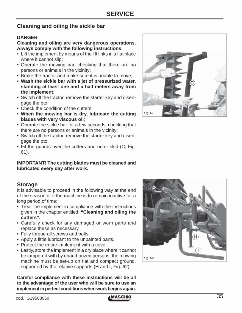
Cleaning and oiling the sickle bar
DANGERCleaning and oiling are very dangerous operations. Always comply with the following instructions:• Lift the implement by means of the lift links in a fl at place
where it cannot slip;• Operate the mowing bar, checking that there are no
persons or animals in the vicinity;• Brake the tractor and make sure it is unable to move;• Wash the sickle bar with a jet of pressurized water,
standing at least one and a half meters away from the implement;
• Switch off the tractor, remove the starter key and disen-gage the pto;
• Check the condition of the cutters;• When the mowing bar is dry, lubricate the cutting
blades with very viscous oil;• Operate the sickle bar for a few seconds, checking that
there are no persons or animals in the vicinity;• Switch off the tractor, remove the starter key and disen-
gage the pto;• Fit the guards over the cutters and outer skid (C, Fig.
61).
IMPORTANT! The cutting blades must be cleaned and lubricated every day after work.
StorageIt is advisable to proceed in the following way at the end of the season or if the machine is to remain inactive for a long period of time:• Treat the implement in compliance with the instructions
given in the chapter entitled: “Cleaning and oiling the cutters”.
• Carefully check for any damaged or worn parts and replace these as necessary.
• Fully torque all screws and bolts.• Apply a little lubricant to the unpainted parts.• Protect the entire implement with a cover.• Lastly, store the implement in a dry place where it cannot
be tampered with by unauthorized persons; the mowing machine must be set-up on fl at and compact ground, supported by the relative supports (H and I, Fig. 62).
Careful compliance with these instructions will be all to the advantage of the user who will be sure to use an implement in perfect conditions when work begins again.
Fig. 62
Fig. 61
H
I
C
SERVICE
36 cod. G19503950
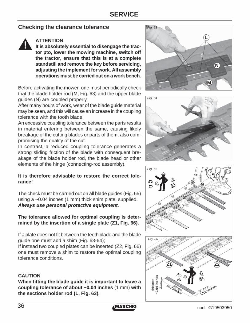
Checking the clearance tolerance Fig. 63
Fig. 64
302 mm30 mm1
mm
1.18 inches11.9 inches
thic
knes
~0.0
4 in
ches
Fig. 65
Fig. 66
Z2Z1
ATTENTIONIt is absolutely essential to disengage the trac-tor pto, lower the mowing machine, switch off the tractor, ensure that this is at a complete standstill and remove the key before servicing, adjusting the implement for work. All assembly operations must be carried out on a work bench.
Before activating the mower, one must periodically check that the blade holder rod (M, Fig. 63) and the upper blade guides (N) are coupled properly.After many hours of work, wear of the blade guide material may be seen, and this will cause an increase in the coupling tolerance with the tooth blade.An excessive coupling tolerance between the parts results in material entering between the same, causing likely breakage of the cutting blades or parts of them, also com-promising the quality of the cut.In contrast, a reduced coupling tolerance generates a strong sliding friction of the blade with consequent bre-akage of the blade holder rod, the blade head or other elements of the hinge (connecting-rod assembly).
It is therefore advisable to restore the correct tole-rance!
The check must be carried out on all blade guides (Fig. 65) using a ~0.04 inches (1 mm) thick shim plate, supplied.Always use personal protective equipment.
The tolerance allowed for optimal coupling is deter-mined by the insertion of a single plate (Z1, Fig. 66).
If a plate does not fi t between the teeth blade and the blade guide one must add a shim (Fig. 63-64);If instead two coupled plates can be inserted (Z2, Fig. 66) one must remove a shim to restore the optimal coupling tolerance conditions.
CAUTIONWhen fi tting the blade guide it is important to leave a coupling tolerance of about ~0.04 inches (1 mm) with the sections holder rod (L, Fig. 63).
L
M
N

SERVICE
37cod. G19503950
Only with some models, before disassembling the blade guides (N, Fig. 63), one must previously remove the fi nger blade tie rod (W) in Figure 67. Use a punch to facilitate the operation (T, Fig. 67).Subsequently, only after having made sure that the blade guides have been blocked, one must tighten the fi nger blade again via the nuts, located at both ends, keeping to the 0.59 inches (15 mm) shown in Figure 67. Use a punch to facilitate the operation (T, Fig. 67)This measurement allows to maintain the cutting bar in traction, without bending it downwards.
IMPORTANT: When replacing the teeth or the tooth-holding bar, carry out the check described above. When required, put back the shims to avoid striping or damage.
~15 mm ~15 mm~ 0.59 inches~ 0.59 inches
Fig. 67
W
T

SERVICE
38 cod. G19503950
Extra maintenance
Replacement of section-holding bar (E, fi g. 70)• With the implement resting on the ground, open the
mowing bar.• Remove the expansion pin (B, Fig. 68) and pull out the
section-holding bar (Fig. 69) with the hooking tie rod (C, Fig. 69).
• Insert the new section-holding bar and lock it in place with the expansion pin. Lubricate the cutters with very viscous oil during the assembly phase.
Replacement of sections (D, fi g. 70)• With the implement resting on the ground, open the
mowing bar.• Remove the expansion pin (B, Fig. 68) and slide out the
section-holding bar (Fig. 69).• Remove the damaged section using a pin punch (7, Fig.
4 on page 6). • Rivet a new section with the rivets provided (D, Fig. 70).• Insert the section-holding bar and lock it in place with
the expansion pin.
Fig. 69
B
Fig. 68
C
A
ATTENTIONIt is absolutely essential to disengage the trac-tor pto, lower the mowing machine, switch off the tractor, ensure that this is at a complete standstill and remove the key before servicing, adjusting the implement for work. All assembly operations must be carried out on a work bench.
During all maintenance operations on moving parts, it is important to grease all the points indicated in Figure 57 before starting the machine.
Replacing the cutting blades
ATTENTIONThe expansion pins must be reassembled as shown in Figure 68 (A), by tightening the screw and the conical nut with a torque not exceeding 30 Nm. Every time the expansion pins are disassem-bled and reassembled, one must grease the blade head concerned (C, Fig. 57).

SERVICE
39cod. G19503950
Fig. 73
Fig. 72
Replacement of tooth-holding bar (riveted) (G Fig. 71)• With the implement resting on the ground, open the
mowing bar.• Remove the expansion pin (B, Fig. 68) and slide out the
toothholding bar (Fig. 69).• Insert the new tooth-holding bar and lock it in place with
the expansion pin.
Replacement of tooth (riveted) (F fi g. 71)• With the implement resting on the ground, open the
mowing bar.• Remove the expansion pin (B, Fig. 68) and slide out the
toothholding bar (Fig. 69).• Remove the damaged tooth using a pin punch.• Rivet a new tooth with the rivets provided (F, Fig. 71).• Insert the tooth-holding bar and lock it in place with the
expansion pin.
ATTENTIONIt is absolutely essential to disengage the tractor pto, lower the mowing machine, switch off the tractor, ensure that this is at a com-plete standstill and remove the key before servicing, adjusting the implement for work. All assembly operations must be carried out on a work bench.
Replacement of bar holding removable tooth• With the implement resting on the ground, raise the
mowing bar and secure it with the hooking tie rod.• Unscrew all the tooth fastening screws (Fig. 72).• Remove all the teeth (Fig. 73).• Remove the expansion pin and slide out the bar.• Insert the new tooth-holding bar and lock it in place with
the expansion pin.• Reposition the teeth by fi xing them with new screws and
washers.
Replacement of removable tooth• With the implement resting on the ground, raise the
mowing bar and secure it with the hooking tie rod.• Unscrew the screws of the tooth to be replaced (Fig. 72).• Pull out the tooth (Fig. 73) and replace it with a new
one, blocking it with new screws and washers. For this it would be advisable to use a torque wrench, respecting the values of 30 Nm.
D
E
F
G
Fig. 70
Fig. 71

SERVICE
40 cod. G19503950
Replacing the anti-vibration yokes
Dismantling• Remove the protection.• Remove the expansion pins (M, Fig. 74).• Loosen and remove screws L, H, I (Fig. 74).• Remove the support (N, Fig. 74).• Remove the yokes (P, Fig. 74).
Assembly1) Insert the new yokes with the intermediate spacer (O,
Fig. 74).2) Refi t the support and screws L, H, I without tightening
them.3) Couple the yokes to the connecting rods and fasten
them with the expansion pins.4) Align the yokes properly using a pin or screw (M20)
(Fig. 74).5) Tighten screws H and I.6) Tighten screw L securely. CAUTION: do not tighten the screws without having alig-ned the yokes correctly (P, Fig. 75).7) Refi t the protection.
Verifying the assemblyThe bolt must be removed manually with no force; if ne-cessary, repeat the tightening steps of screws “H”, “I” and then “L”.
Replacement of belts• Unscrew the screws (Q, Fig. 76) and remove the pro-
tective casing.• Loosen the belt tensioner completely (R, Fig. 76).• Replace the worn belts with new ones.• Put these at the optimum tension using the belt tensioner.
Belt play should not exceed 1 inch.• Put the protective casing back in position and fi x it in
place with the screws (Q, Fig. 76).
Replacement of pulleysNotes for replacement of pulleys, if necessary.• Unscrew the screws (Q, Fig. 76) and remove the pro-
tective casing.• Loosen the belt tensioner completely (R, Fig. 76).• Remove the belts.To replace the driving pulley (S, Fig. 77), turn it clockwise; vi-ceversa, turn the driven pulley (T, Fig. 77) counterclockwise. Fig. 77
Fig. 76
HI
L
N
M
O
P
H
I
L
P
Q
R
S
T
Fig. 74
Fig. 75

TRANSPORT ON THE ROAD
41cod. G19503950
Fig. 80
Transport on road
For transport, adjust and fi x the chains of the side lifting arms of the tractor; lift the mowing bar (Fig. 78); secure it with the hooking tie rod (A, Fig. 79); slide in the safety hook (B, Fig. 79); cover the cutting blades and the outer mowing bar support with the guards provided (Fig. 80); lift the implement; put the hydraulic lifting command lever in the locked position.
Transport on Road• When driving on public roads, be sure to follow the
highway code of the country involved.• Any transport accessories must be provided with sui-
table signs and guards.• It is very important to remember that road holding ca-
pacity as well as direction and braking capacity can be infl uenced, sometimes con-siderably, by equipment being either carried or towed.
• When negotiating curves, be aware of the variation in centrifugal force exerted in a position other than that of the center of gravity, with and without the equipment in tow. Also pay greater attention on sloping roads or ground.
• For displacements beyond the work area, the equipment must be placed in the transportation position.
• When the dimensions of carried or partially-carried equipment conceal the tractor’s signalling and lighting devices, these must also be installed on the equipment itself, in conformity with regulations of the highway code of the country involved. When in operation make sure that the lighting system is in perfect working order.
Fig. 78
Fig. 79
B
A

DEMOLITION AND DISPOSAL
42 cod. G19503950
Demolition and disposal
This operation is to be carried out by the customer.Before demolishing the machine, you are advised to carefully check its physical condition and ascer-tain whether there are any parts of the structure that may be susceptible to structural collapse or breakage during demolition.
The customer should operate in compliance with the environment protection laws in force in his/her country.
CAUTIONThe machine demolition operations should be carried out by skilled personnel only, equipped with suitable protective clothing (safety footwear and gloves) and auxiliary tools and equipment. All the disassembly operations for demolition should be carried out with the machine stopped and detached from the tractor.
Before demolishing the machine, you are advised to render harmless all the parts that may be a source of danger and therefore:
• scrap the structure using specialized fi rms,• remove any electrical apparatus according to the laws in force,• collect oils and greases separately, to be disposed of through specialized fi rms, in accordance
with the regulations of the country in which the machine was used.
When the machine is demolished the identifi cation label must be destroyed together with this manual.

ASSEMBLY
43cod. G19503950
Foreword
This chapter describes the phases involved in assembling a crated mower. When handling and assem-bling the unit, and subsequently during use and maintenance, always use suitable personal protection devices (A): always wear suitable clothing and the indicated protections. See the operating manual supplied with the unit for indication of the symbols used in this manual. When handling the unit, lift it by hooking up the special attachments and using a suitable hoist or crane rated for the weight of the unit. This operation is quite dangerous and must only be performed by prepared, responsible person-nel. The machine weight is indicated on the ID label. The hook-up points are identifi ed by the “hook” symbol (B). When moving the unit, make certain that all protections and safety devices are in place.
A B
FIORE 175 (X2) 234 - 92 70 - 27.5 74 - 29 520 - 1145
FIORE 205 (X2) 234 - 92 70 - 27.5 74 - 29 560 - 1235
FIORE 235 (X2) 275 - 108 73 - 28.7 72,5 - 28.5 600 - 1320
FIORE 175 (X5) 234 - 92 140 - 55 100 - 39 1200 - 2640
FIORE 205 (X5) 234 - 92 140 - 55 100 - 39 1300 - 2860
FIORE 235 (X5) 234 - 92 140 - 55 100 - 39 1400 - 3085
A B C (cm - inch) (kg - lb)(cm - inch) (cm - inch)
TYPE
A
B
C
Dimensions and weight
ASSEMBLY
44 cod. G19503950
3
2
4
1
5
7
6
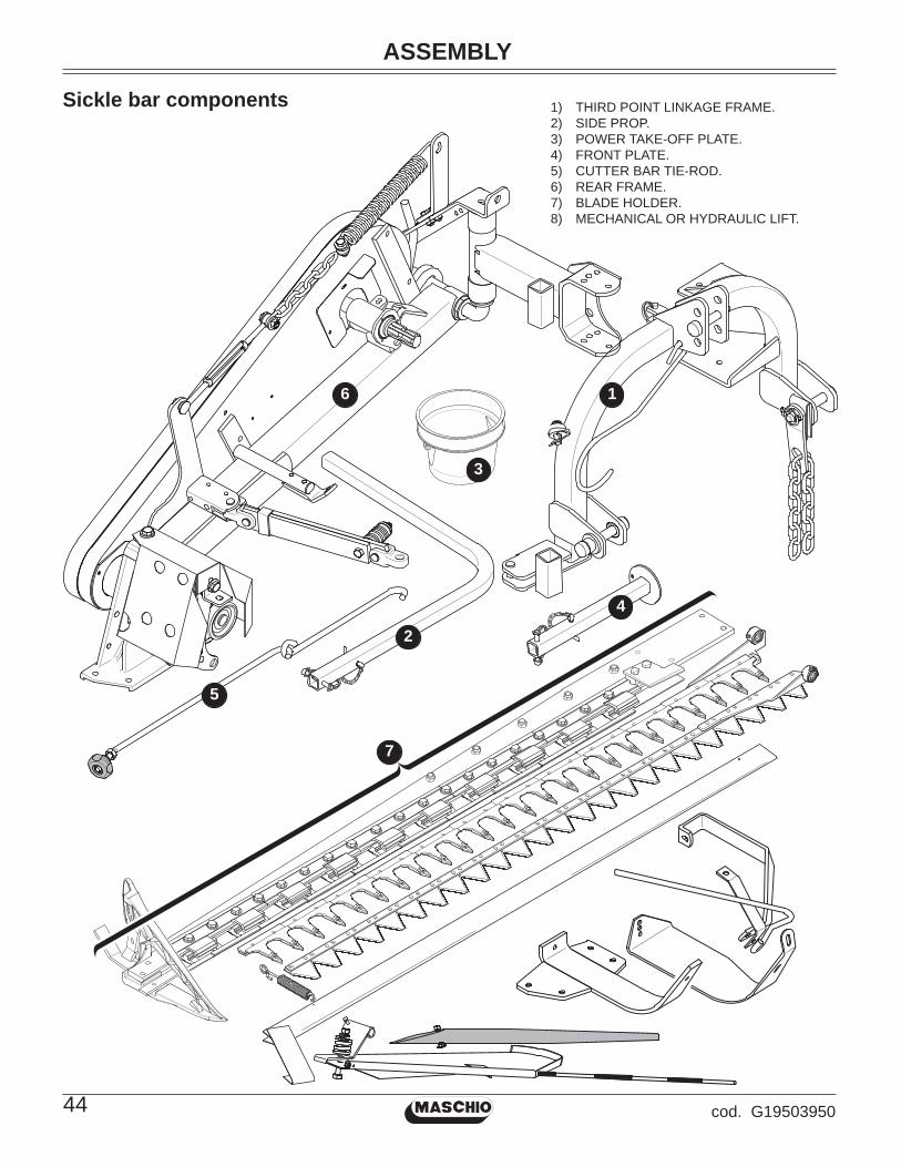
Sickle bar components 1) THIRD POINT LINKAGE FRAME.2) SIDE PROP.3) POWER TAKE-OFF PLATE.4) FRONT PLATE.5) CUTTER BAR TIE-ROD.6) REAR FRAME.7) BLADE HOLDER.8) MECHANICAL OR HYDRAULIC LIFT.

ASSEMBLY
45cod. G19503950
Mechanical lifting
Hydraulic lifting8

ASSEMBLY
46 cod. G19503950
1.0
2.0 3.0
M8 x 16

ASSEMBLY
47cod. G19503950
4.0
6.05.0
M12 x 35
ASSEMBLY
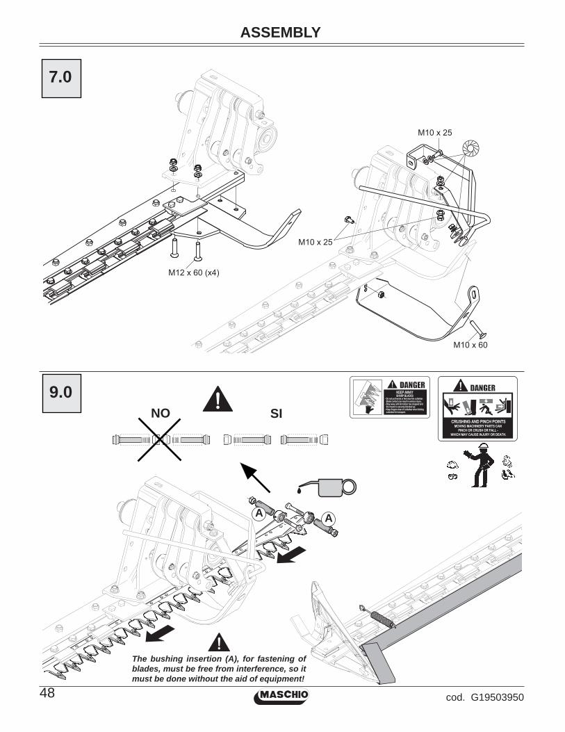
48 cod. G19503950
M12 x 60 (x4)
M10 x 25
M10 x 25
M10 x 60
7.0
CRUSHING AND PINCH POINTSMOVING MACHINERY PARTS CAN
PINCH OR CRUSH OR FALL -
WHICH MAY CAUSE INJURY OR DEATH.
KEEP AWAYSHARP BLADES
- Do not put hands or feet near the cutterbar. Blade contact can result in serious injury.
- Stay away until all motion has stopped and the mower is securely blocked up.
- Keep fingers clear of cutterbar when folding cutterbar for transport.NO SI
9.0
The bushing insertion (A), for fastening of blades, must be free from interference, so it must be done without the aid of equipment!
AA

ASSEMBLY
49cod. G19503950
M12 x 80
M8 x 40
M4 x 35
Do not tighten securing nut (A) on the moving
guide completely: allow for proper movement of
the guide.
(A)
10.09.0
11.0

50 cod. G19503950
L. 154
M16 x40
M20 x200
M12 x40
11.0
51cod. G19503950
SPARE PARTS
Spare parts
Orders must be transmitted through our area dealers and should always include the following indi-cations:
• Type, model and serial number of the machine. These data are punched on the data plate with which every implement is equipped.
• Code number of the required spare part. This will be found in the spare parts catalogue.
• Description of the part and required quantity.
• Means of dispatch. If this item is not indicated, the Manufacturer, while dedicating particular care to this service, shall not be held responsible for delays in delivery caused by cases of force majeure.
Transport expenses shall always be at the consignee’s charge. The goods travel at the purchaser’s risk and peril even when sold ex destination.
NOTE: The terms Right or Left indicated in the descriptions refer to the implement when viewed from the rear side.
Table index
Frame Tav. 10 ......pag. 52Mechanical lifting system Tav. 20 ......pag. 54Transmission Tav. 30 ......pag. 56Hinge Tav. 40 ......pag. 58Cutting blade (tooth riveted) Tav. 50 ......pag. 60Cutting blade(removable tooth) Tav. 60 ......pag. 62Wear-proof skids Tav. 70 ......pag. 64Hydraulic lifting system Tav. 80 ......pag. 66

SPARE PARTS
52 cod. G19503950
TAV.
10
6362
60
6
464
5
19
607
38
50
18
37
37 38
16
2
3
39
4544 40
55
38 37
46
45
1
27
47
28
57
56
29
42
4344
45
26
63
626035
34
4936
36
49
9
30
6059
61
15
1337
3351
46 47 14
4538
3252
5354
55
45
4440
41
23
24
25
20
60
7
65
22
21
4
31
5812
3
17
31258
58
35
67 33
6865
67348
8
57
1168
3
6670
67
7236
73
10
46
69 -
(0
,5 m
t)
7174
64

Pos.
C
od.
Des
crip
tion
SPARE PARTS
53cod. G19503950
Pos.
C
od.
Des
crip
tion
1 G
1221
7592
A
SS
.3R
D P
OIN
T FR
AM
E ‘0
92
G12
2178
21
JOIN
T FB
R3
G20
9700
35
WA
SH
ER
32X
4X13
4 F0
1020
403
BO
LT M
6X1X
16 U
5739
8.8
ZN
5 F0
1410
037
WA
SH
ER
M6
6,4X
12,5
X1,
6 U
6592
ZN6
F022
5068
0 TH
RE
AD
ED
INS
ER
T M
6X13
ZN
7 F0
1020
092
BO
LT 8
X11
0 57
37 8
.G G
ALV
AN
IZ.
8 G
1221
9140
S
PR
ING
LIN
K P
LATE
9 G
1221
8170
A
SS
.ING
SN
AP
TIG
HTE
.FB
R P
LUS
10
G12
2192
00
TIE
CU
TTIN
G B
AR
FB
R P
LUS
0911
G
1621
4150
R
OW
-MA
RK
ER
SP
RIN
G Z
N12
F0
1430
071
WA
SH
ER
D12
DIN
679
8 D
.INT.
ZN13
G
1221
7810
P
RO
P TU
BE
14
G12
2176
50
FRO
NT
PR
OP
15
G12
2178
01
AS
S.H
ING
E H
OLD
ER
AR
M ‘0
916
G
2103
0010
A
RM
AR
TIC
ULA
TIO
N17
G
1221
8190
JU
NC
TIO
N E
LEM
EN
T FB
R P
LUS
18
G21
1203
19
HIN
GE
AR
M S
PR
ING
FB
940
19
G12
2364
71
PD
P G
UA
RD
20
G21
1202
15
INN
ER
PR
OTE
CTI
ON
CA
SE
FB
/S21
G
2112
0216
O
UTE
RP
RO
TEC
TIO
N C
AS
E F
B/S
22
G21
1202
17
WIN
DO
W C
OV
ER
CO
NTR
. FB
/S23
G
1221
9160
B
LAD
E T
EN
SIO
NE
R A
SS
EM
BLY
24
F012
0030
6 N
UT
M14
X2
25
F062
2002
3 4-
LOB
E H
AN
DW
HE
EL
M14
26
F201
2040
0 S
HA
FT H
OO
K S
UP
PO
RT
27
G21
0300
07
TRA
CTO
R C
OU
PLI
NG
PLA
TE28
G
2103
0035
C
HA
IN L
.900
29
G21
0300
34
FRA
ME
CO
UP
LIN
G30
G
2112
0308
S
AFE
TY H
OO
K C
OU
PLI
NG
FB
31
G12
2174
40
FRA
ME
LIN
K H
OO
K Z
N32
G
1221
8160
S
LID
ING
RO
D33
G
1221
7761
S
NA
P TI
E R
OD
GU
IDE
34
G12
2179
50
FOR
K F
OR
TR
IP T
IE-R
OD
35
G66
2480
64
HIN
GE
AR
M B
US
HIN
G F
B.
36
F201
0050
4 U
BO
LT P
IN D
.16X
4537
G
2103
0027
R
UB
BE
R B
LOC
KS
38
G20
9700
67
WA
SH
ER
54X
5X32
39
F201
0004
7 B
OLT
D22
L10
8 C
43 Z
N40
G
2101
0042
B
US
HIN
G 1
.-2. P
OIN
T41
F2
0100
115
GA
SPA
RD
O P
IN 2
2X14
4 ZN
42
F201
0003
5 B
OLT
D19
L86
C43
ZN
43
G12
2176
60
THIR
D P
OIN
T B
US
H44
F0
2200
507
SN
AP
PIN
D9
B/8
3 ZN
45
G13
8123
11
CH
AIN
WIT
H S
PR
ING
CAT
CH
46
F022
0056
2 S
NA
P P
IN D
.8X
70
ZN47
F0
2200
272
SP
LIT
PIN
10
X60
133
6 G
ALV
AN
.48
G
1221
9180
C
HA
IN D
.8
L.25
5 ZN
49
F022
0019
5 S
PLI
T P
IN 4
X30
U13
36 Z
N50
F0
2200
260
SP
LIT
PIN
8 X
60 1
336
ZN51
F0
1020
176
BO
LT M
12X
1,75
X13
0 57
37 8
.8 Z
N52
G
2112
0301
C
ON
E D
ISC
ON
NE
CT
FB94
053
F0
2400
013
GA
S S
PR
ING
38X
75 S
PE
C.
54
G22
3100
47
RE
AR
AR
M B
US
HIN
G D
P55
F0
1230
059
LOC
K-N
UT
M12
X1,
75 D
982
ZN56
F0
1020
476
BO
LT M
10X
1,5X
30 U
5739
8.8
ZN
57
F012
2003
3 N
UT
M10
X 1
,5
D98
0 8
ZN
58
F010
2052
8 B
OLT
M12
X1,
75X
40 U
5739
10.
9ZN
59
F010
2007
2 B
OLT
M8X
1,25
X50
U57
37 8
.8 Z
N60
G
2097
0140
W
AS
HE
R 2
0X2X
8,5
61
F012
3003
4 LO
CK
NU
T M
8X1,
25 D
982
8 ZN
62
F014
3005
9 W
AS
HE
R M
8 8,
4X15
X0,
8 U
8842
J ZN
63
F012
0024
4 N
UT
M8
X1,
25 U
5588
6.8
ZN
64
F014
2003
7 W
AS
HE
R M
6 6,
4X24
X2
U65
93 Z
N65
F0
2250
708
TIE
-RO
D 2
-EY
ES
M12
GA
LVA
NIZ
ED
66
F014
1007
6 W
AS
HE
R 1
2 13
X 2
4X2,
5 U
6592
ZN
67
F012
2004
8 N
UT
M12
X1,
75
D98
0 8
ZN
68
F010
2015
2 S
CR
EW
M12
X1,
75X
40
5737
8.8
ZN
69
F051
5048
4 E
SP
IRA
L P
RO
TEC
IEN
D.2
7-32
70
F010
6012
0 B
OLT
M12
X1,
75X
40 U
5732
8,8
ZN
71
F010
2047
9 B
OLT
M10
X1,
5X35
U57
39 8
.8 Z
N72
F0
1410
100
WA
SH
ER
M16
17X
30X
3 U
6592
ZN
73
F022
0036
3 S
PR
ING
SP
LIT
PIN
3X
62
ZN74
F0
1420
060
WA
SH
ER
10,
5X30
TAV.
10
FRA
ME

SPARE PARTS
54 cod. G19503950
TAV.
20
15
15
16
1617
17
18
19
5
20
2122
23
24
24
9
10
1012
25
25
8
88
7 7
2627
28
29
30
1717
BL
AC
K -
31
8
8
7
6 -
RE
D
9
4
5
103
21
1314
11
12
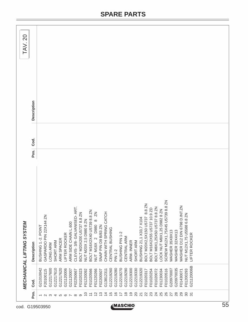
Pos.
C
od.
Des
crip
tion
SPARE PARTS
55cod. G19503950
Pos.
C
od.
Des
crip
tion
TAV.
20
MEC
HA
NIC
AL
LIFT
ING
SYS
TEM
1 G
2101
0042
B
US
HIN
G 1
.-2. P
OIN
T2
F201
0011
5 G
AS
PAR
DO
PIN
22X
144
ZN3
G12
2176
00
LON
G A
RM
4 G
1221
7610
S
HO
RT
AR
M5
G12
2176
20
AR
M S
PAC
ER
6 G
2112
0006
LI
FTE
R R
OC
KE
R7
G21
1200
07
AR
M S
IDE
CH
AIN
L.6
008
F022
5066
7 C
LEV
IS- 3
/8- G
ALV
AN
ISE
D- A
RT.
9 F0
1020
323
BO
LT M
20X
200
U57
37 8
.8 Z
N10
F0
1220
092
NU
T M
20X
2,5
D98
0 8
ZN11
F0
1020
566
BO
LT M
16X
2X40
U57
39 8
.8 Z
N12
F0
1220
266
NU
T M
16X
2
D
980
8
ZN13
F0
2200
507
SN
AP
PIN
D9
B/8
3 ZN
14
G13
8123
11
CH
AIN
WIT
H S
PR
ING
CAT
CH
15
G12
2192
60
CE
NTR
AL
BU
SH
ING
16
G12
2192
80
PIN
1-2
17
G12
2192
70
BU
SH
ING
PIN
1-2
18
G12
2192
90
CE
NTR
AL
AR
M19
G
1221
9300
A
RM
- IN
NE
R20
G
1221
9330
S
HO
RT
AR
M21
G
1221
9320
B
US
HIN
G 2
1,1
X33
,7 X
104
22
F010
2031
7 B
OLT
M20
X2,
5X15
0 U
5737
8.8
ZN
23
F010
2025
4 B
OLT
M16
X2X
55 U
5737
10.
9 ZD
24
F010
2007
2 B
OLT
M8X
1,25
X50
U57
37 8
.8 Z
N25
F0
1230
034
LOC
K N
UT
M8X
1,25
D98
2 8
ZN26
F0
1020
516
SC
RE
W M
12X
1,75
X45
U57
39 8
.8 Z
N27
G
2097
0007
W
AS
HE
R 3
5X8X
1328
G
2097
0035
W
AS
HE
R 3
2X4X
1329
F0
1430
071
WA
SH
ER
D12
DIN
679
8 D
.INT.
ZN30
F0
1200
293
NU
T M
12X
1,75
U55
88 6
.8 Z
N31
G
2112
0006
B
LIFT
ER
RO
CK
ER
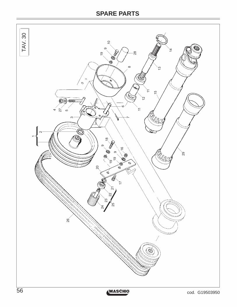
SPARE PARTS
56 cod. G19503950
TAV.
30
1
4 27 5
2
19
8
6
7
910
28
9
1919
9
16
1112
11
13
14
15
18
29
17
2221
2324
26
25
3
20

Pos.
C
od.
Des
crip
tion
SPARE PARTS
57cod. G19503950
Pos.
C
od.
Des
crip
tion
TAV.
30
TRA
NSM
ISSI
ON
1 G
2112
0117
3
GR
OO
VE
DR
IVIN
G P
ULL
EY
2 G
2097
0129
W
AS
HE
R 4
8X3X
30-5
3 G
2103
0015
P
TO S
UP
PO
RT
4 F0
1200
306
NU
T M
14X
25
G21
1203
18
BE
LT R
EG
ISTE
R A
SS
Y. F
B94
06
G21
1200
13
INTE
RM
. TR
AN
SM
. SU
PP.
PIN
7 F0
2200
227
PIN
5X
30
U13
36 Z
N8
F051
5040
3 P
OW
ER
TA
KE
-OFF
PR
OTE
CTI
ON
HO
US
9 F0
1430
059
WA
SH
ER
M8
8,4X
15X
0,8
U88
42J
ZN10
F0
1020
432
BO
LT M
8 X
1,25
X16
U57
39 8
.8 Z
N11
F0
4010
174
BE
AR
ING
D30
D62
B16
620
6 2R
S12
G
2103
0020
S
PAC
ER
13
G21
1201
52
PO
WE
R T
AK
E-O
FF F
B14
F0
2050
392
SE
EG
ER
RIN
G E
. 62X
2 U
7437
C70
15
F080
1193
1 U
NIV
ER
SA
L JO
INT
B3
1200
AM
16
F012
0024
4 N
UT
M8
X1,
25 U
5588
6.8
ZN
17
F010
6004
5 B
OLT
8X
40 5
732
4.6
GA
LVA
NIZ
ED
18
F010
2044
0 S
CR
EW
M8X
1,25
X25
U57
39 8
.8 Z
N19
G
2097
0140
W
AS
HE
R 2
0X2X
8,5
20
G21
1202
26
BE
LT T
IGH
TEN
ER
RO
LLE
RS
SU
PP
OR
T21
F0
2050
056
SE
EG
ER
RIN
G E
. 17X
1 U
7435
C70
22
F040
1016
1 B
EA
RIN
G D
17 D
40 B
12 6
203
2RS
23
G21
1201
19
3 G
RO
OV
E P
.TIG
HTE
N. P
IN24
G
6624
8107
B
ELT
TIG
HTE
NE
R L
.70
FB25
G
2112
0121
TI
GH
TEN
ER
RO
LLE
R 3
G. C
P26
F0
6010
240
BE
LT- B
93
27
F014
1008
8 W
AS
.M14
15
X 2
8X2,
5 U
6592
ZB
28
G19
0021
31
PD
P G
UA
RD
29
F080
1193
3 U
NIV
. JO
INT
PR
OTE
CTI
ON
B3X
1200
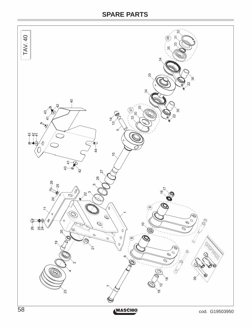
SPARE PARTS
58 cod. G19503950
TAV.
40
2
3
4
5
6
7
8
10
11
16
1920
21
22
23
242526
2425
26
17
1
22
29
30
3133
35
35
34
34
32
36
36
12
1315
2728
18 39
18
14
40
44
41
414243
43
43
42
42
41
37
32
38
22
9
9

Pos.
C
od.
Des
crip
tion
SPARE PARTS
59cod. G19503950
Pos.
C
od.
Des
crip
tion
TAV.
40
HIN
GE
1 G
1223
6500
H
ING
E2
F040
1017
1 B
EA
RIN
G D
30 D
62 B
16
6206
Z3
F040
1036
3 B
EA
RIN
G D
HK
502
54
F020
5039
2 S
EE
GE
R R
ING
E. 6
2X 2
U74
37 C
705
F030
1106
9 S
EA
LIN
G R
ING
DH
50X
58X
46
G21
1201
26
CO
NIC
PIN
FB
7 G
1223
6540
A
NTI
VIB
.SH
AFT
SU
PP.
FOR
K8
G12
2366
10
FOR
K S
PAC
ER
(HIN
GE
SID
E)
9 G
1223
6600
A
NTI
VIB
RAT
ION
FO
RK
CO
MP.
10
G21
1201
18
CE
NTR
AL
FOR
KS
SPA
CE
R11
G
1223
6690
C
ON
NE
CTI
NG
RO
D S
UP
PO
RT
12
G21
1201
37
INTE
RN
AL
RIN
G F
B13
G
2112
0136
P
IN S
PAC
ER
FB
14
G21
1201
27
PIN
GR
UB
-SC
RE
W F
B15
G
2112
0223
H
ING
E S
PIN
DLE
FB
/S16
F0
1460
139
CO
NTA
CT
ELA
ST.
WA
SH
ER
D16
17
F012
3008
5 N
UT
M16
X 2
D98
2 8
ZN18
G
2097
0519
B
OTT
OM
ED
WA
SH
ER
39X
20-2
5X5X
119
G
2112
0221
B
OLT
14X
30 5
931
8.8
20
G12
2365
00
NU
T M
16X
2 U
5588
8.8
ZN
21
F012
2026
6 N
UT
M16
X
2
D98
0 8
ZN
22
F011
0001
1 G
RE
AS
E N
IPP
LE M
6X1
7663
-A Z
N23
G
2112
0118
D
RIV
EN
PU
LLE
Y 3
SH
EAV
ES
24
F014
1006
4 A
RA
ND
. M10
10,
5X20
X2
U65
92 Z
N25
F0
1430
023
WA
SH
ER
D10
DIN
679
8 D
.INT.
ZN26
F0
1020
476
BO
LT M
10X
1,5X
30 U
5739
8.8
ZN
27
F041
0013
1 IN
TER
NA
L IR
. RIN
G 4
5X50
X35
28
F040
1040
9 S
HO
ULD
ER
RIN
G W
R 4
529
G
2117
0020
H
ING
E E
CC
EN
TRIC
30
G66
2481
11
DU
STC
OV
ER
HIN
GE
FB
31
G21
1200
28
PR
OTE
CTI
ON
PLU
G32
F0
2050
403
SE
EG
ER
RIN
G E
.72X
2,5
U74
37 C
7033
F0
2050
112
SE
EG
ER
RIN
G 3
0X 1
,5 U
7435
C70
34
G21
1201
28
PIN
HIN
GE
CO
NN
EC
TIN
G R
OD
FB
35
F040
1021
5 B
EA
RIN
G D
30 D
72 B
19 6
306
2RS
C3
36
F040
1036
2 B
EA
RIN
G D
HK
253
837
G
2112
0153
K
IT- I
NT.
CO
NN
. RO
D B
EA
RIN
G F
B38
G
2112
0154
K
IT- E
XT.
CO
NN
. RO
D B
EA
RIN
G F
B
39
G21
1201
56
KIT
- BLA
DE
FA
STE
NIN
G P
IN F
B40
G
1223
6710
C
ON
NE
CTI
NG
RO
D P
RO
TEC
TIO
N41
F0
1420
037
WA
SH
ER
M6
6,4X
24X
2 U
6593
ZN
42
F014
3004
7 W
AS
HE
R D
6 D
IN 6
798
D.IN
T.G
ALV
.43
F0
1020
403
BO
LT M
6X1X
16 U
5739
8.8
ZN
44
F022
5068
0 TH
RE
AD
ED
INS
ER
T M
6X13
ZN
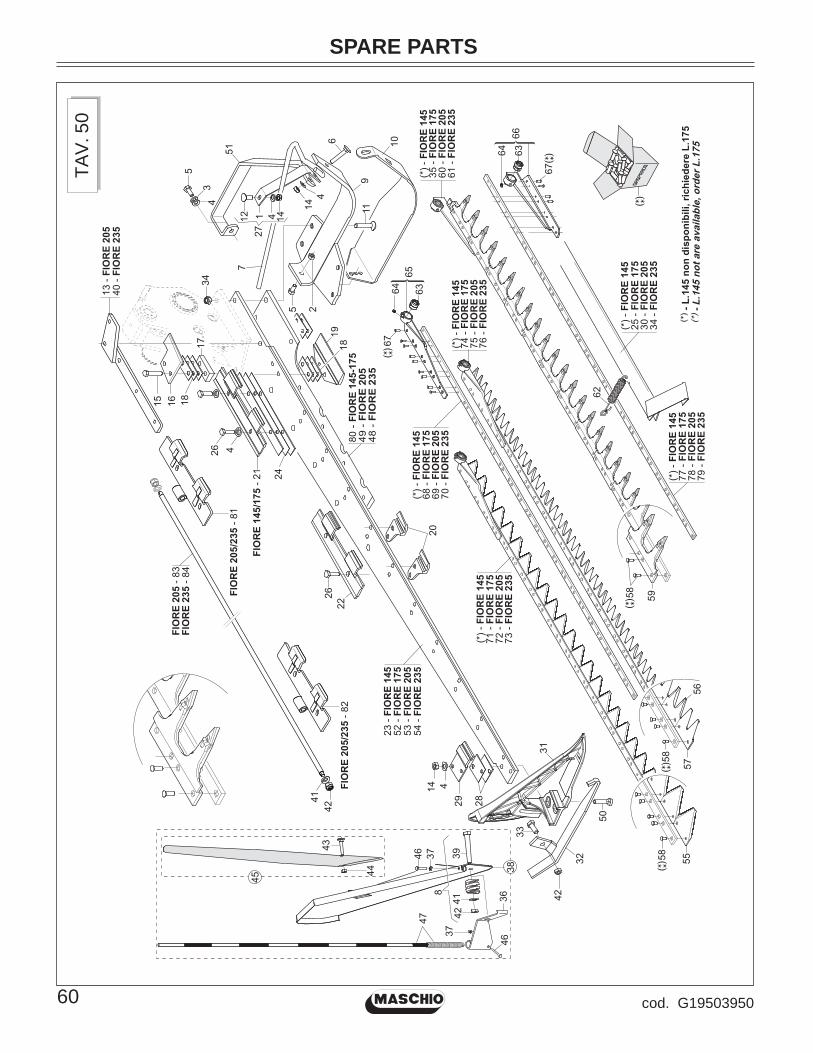
SPARE PARTS
60 cod. G19503950
TAV.
50
19
11
52 -
FIO
RE
175
23 -
FIO
RE
145
53 -
FIO
RE
205
54 -
FIO
RE
235
33
50
31
32
42
24
34
5
144
7
6 10
9
2
80 -
FIO
RE
14
5-1
75
49
- F
IOR
E 2
05
48
- F
IOR
E 2
35
5
4
51
3
2829
14 4
27
43
44
473746
37
36
8
39
45
4142
3846
22
20
26 4
26
555858
5756
5958
6764 63
65
68 -
FIO
RE
175
69 -
FIO
RE
205
70 -
FIO
RE
235
67
64 63
77 -
FIO
RE
175
79 -
FIO
RE
235
78 -
FIO
RE
205
66
71 -
FIO
RE
175
72 -
FIO
RE
205
73 -
FIO
RE
235
74 -
FIO
RE
175
76 -
FIO
RE
235
75 -
FIO
RE
205
35 -
FIO
RE
175
61 -
FIO
RE
235
60 -
FIO
RE
205
- L
.145 n
on
dis
po
nib
ili, r
ich
ied
ere
L.1
75
- L
.145 n
ot
are
availab
le, o
rder
L.1
75
FIO
RE
14
5/1
75 -
21
FIO
RE
205
- 8
3F
IOR
E 2
35
- 8
4
FIO
RE
205/2
35
- 8
1
42
FIO
RE
205/2
35
- 8
2
41
15 16 18
17 18
25 -
FIO
RE
175
34 -
FIO
RE
235
62
30 -
FIO
RE
205
12 1441
40 -
FIO
RE
235
13 -
FIO
RE
205

Pos.
C
od.
Des
crip
tion
SPARE PARTS
61cod. G19503950
Pos.
C
od.
Des
crip
tion
TAV.
50
CU
TTIN
G B
LAD
E (T
OO
TH R
IVET
ED)
1 G
2112
0321
IN
NE
R S
LID
E S
PAC
ER
FB
940
2 F0
1200
270
NU
T M
10X
1,5
U55
88
6.8
ZN
3 F0
1430
023
WA
SH
ER
D10
DIN
679
8 D
.INT.
ZN4
F014
1006
4 A
RA
ND
. M10
10,
5X20
X2
U65
92 Z
N5
F010
2047
2 B
OLT
M10
X1,
5X25
U57
39 8
.8 Z
N6
F010
6008
1 B
OLT
10X
60 5
732
4.6-
GA
LVA
NIZ
7 G
2112
0322
H
ING
E P
RO
TEC
TIO
N F
B94
08
G21
1201
33
SW
ATH
BO
AR
D B
OLT
AS
SY.
FB
9 G
1920
5340
IN
TER
NA
L R
UN
NE
R’0
9 A
SS
.BLY
10
G21
1203
24
RU
NN
ER
WID
E IN
T. S
LID
E F
B94
011
F0
1030
121
BO
LT 1
2X60
593
3 8.
8 G
ALV
AN
IZ.
12
F010
6006
9 B
OLT
10X
30 5
732
4.6
13
G13
0181
40
UP
PE
R R
EIN
FOR
CE
D B
AR
2,0
5 D
NE
14
F012
2003
3 N
UT
M10
X 1
,5
D98
0 8
ZN
15
F010
2011
4 B
OLT
M10
X 1
,5X
50 U
5737
8.8
ZN
16
G21
1203
12
SU
P.IN
TER
NA
L B
LAD
E G
UID
E17
G
2112
0231
S
HIM
S M
M.1
0 FB
/S18
G
2112
0044
S
HIM
S- L
OW
ER
INT.
GU
IDE
19
G21
1200
45
INTE
RN
AL
LOW
ER
BLA
DE
GU
IDE
20
G21
1200
42
LOW
ER
BLA
DE
GU
IDE
21
G21
1202
32
UP
PE
R IN
TER
NA
L B
LAD
E G
UID
E22
G
2112
0041
U
PP
ER
BLA
DE
GU
IDE
23
G21
1203
14
BA
R M
T. 1
.45
FB94
024
G
2112
0320
S
HIM
S- U
PP
ER
BLA
DE
GU
IDE
25
G21
1200
54
GU
AR
D -
PR
OTE
CTI
ON
MT.
1-75
26
F010
2047
9 B
OLT
M10
X1,
5X35
U57
39 8
.8 Z
N27
G
1301
3120
C
OM
PLE
TE S
PAC
ER
28
G21
1200
40
SH
IMS
MM
.1 U
PP
ER
EX
T. G
UID
E29
G
2112
0039
U
PP
ER
OU
T. B
LAD
E G
UID
E30
G
2112
0112
C
OM
PL.
PR
OTE
CTI
ON
MT.
2-05
31
G19
2009
03
OU
TER
BA
R S
UP
PO
RT
FBR
32
G21
1200
38
EX
T. R
UN
NE
R S
LID
E33
F0
1020
512
BO
LT M
12X
1,75
X35
573
9 8.
8 ZN
34
G21
1202
66
CO
MP
L. P
RO
TEC
TIO
N .M
T.2-
35 F
B/
35
G13
0138
61
CO
MP
L.R
IB.T
OO
TH B
LAD
E F
BR
1,7
536
G
1301
1650
IN
DIC
ATIO
N B
AR
SU
PP
OR
T37
F0
1230
016
NO
RM
.SE
LF-L
OC
KIN
G N
UT
4 G
ALV
AN
38
G21
1201
34
SW
ATH
BO
AR
D -
AS
SY.
FB
39
F010
6010
5 B
OLT
12X
80 5
732
4.6
40
G13
0181
10
UP
PE
R R
EIN
FOR
CE
D B
AR
2,3
5 D
NE
41
F014
1007
6 W
AS
HE
R 1
2 13
X 2
4X2,
5 U
6592
ZN
42
F012
3005
9 LO
CK
-NU
T M
12X
1,75
D98
2 ZN
43
F010
6004
5 B
OLT
8X
40 5
732
4.6
GA
LVA
NIZ
ED
44
F012
3003
4 LO
CK
NU
T M
8X1,
25 D
982
8 ZN
45
G20
8000
61
SW
ATH
BO
AR
D R
OD
AS
SY.
46
F010
2001
2 B
OLT
4X
40 5
737
8.G
GA
LVA
NIZ
.47
G
1301
1660
IN
DIC
ATIN
BA
R48
G
1301
7611
5
HO
LES
BA
R R
EIN
FOR
CE
ME
NT
49
G13
0176
01
4 H
OLE
S B
AR
RE
INFO
RC
EM
EN
T50
F0
1030
501
BO
LT T
SQ
ST
10X
45 8
.851
G
1301
4250
G
UA
RD
RO
D52
G
1301
2221
B
AR
DN
E 1
,75
FBR
PLU
S53
G
1301
2261
B
AR
DN
E 2
,05
FBR
PLU
S54
G
1301
2301
B
AR
MT.
2,3
555
G
2112
0243
C
UT
SE
CTI
ON
FB
/S56
G
1301
3550
LO
WE
R D
OU
BLE
PO
INT
SE
CTI
ON
57
G13
0135
40
UP
PE
R D
OU
BLE
PO
INT
SE
CTI
ON
58
F022
5051
9 R
IVE
TS T
SC
6X
13,8
QTY
200
59
G13
0142
40
RIV
ETE
D T
OO
TH E
VO
1160
G
1301
3871
C
OM
PL.
RIB
.TO
OTH
BLA
DE
FB
R 2
,05
61
G13
0138
81
CO
MP
L.R
IB.T
OO
TH B
LAD
E F
BR
2,3
562
G
6533
7002
TR
AC
TIO
N S
PR
ING
GU
AR
D F
S63
G
2112
0048
B
US
HIN
G- B
LAD
E H
EA
D 2
8X20
X24
64
F011
0001
1 G
RE
AS
E N
IPP
LE M
6X1
7663
-A Z
N65
G
2112
0267
IN
TER
NA
L S
EC
TIO
N B
LAD
EH
EA
D66
G
2112
0259
E
XT.
CO
MP
LETE
TO
OTH
BLA
DE
HE
AD
67
F022
5052
0 R
IVE
TS T
SC
6X
19,8
QTY
154
68
G21
1202
46
RO
D S
EC
TIO
NS
MT.
1.7
5 FB
/S69
G
2112
0247
R
OD
SE
CTI
ON
S M
T. 2
.05
FB/S
70
G21
1202
48
RO
D S
EC
TIO
NS
MT.
2.3
5 FB
/S71
G
2112
0240
C
UTT
ING
BLA
DE
MT.
1-75
FB
/S72
G
2112
0241
C
OM
PL.
SE
CTI
ON
-HO
LDIN
G B
AR
2,0
573
G
2112
0242
C
OM
PL.
SE
CTI
ON
-HO
LDIN
G B
AR
2,3
574
G
1301
3620
D
OU
BLE
-TIP
SE
CTI
ON
BLA
DE
1.7
575
G
1301
3630
D
OU
BLE
ED
GE
D B
LAD
E G
UID
E S
EC
T76
G
1301
3640
D
OU
BLE
PO
INT
SE
C.B
LAD
E 2
,35
77
G21
1202
51
BLA
DE
RO
D- M
T. 1
.75
FB/S
78
G21
1202
52
BLA
DE
RO
D- M
T. 2
.05
FB/S
79
G21
1202
53
BLA
DE
RO
D- M
T. 2
.35
FB/S
80
G13
0176
21
2 H
OLE
S B
AR
RE
INFO
RC
EM
EN
T81
G
1301
8040
U
PP
ER
INN
ER
BLA
DE
GU
IDE
DN
82
G13
0180
50
UP
PE
R B
LAD
E G
UID
E D
N83
G
1301
8060
TI
E-R
OD
M12
L.1
650
-30
-30
84
G13
0180
70
TIE
-RO
D M
12 L
.195
5 -3
0 -3
0

SPARE PARTS
62 cod. G19503950
TAV.
60
19
11
52 -
FIO
RE
175
89 -
FIO
RE
145
53 -
FIO
RE
205
54 -
FIO
RE
235
426
2523
2829
30
14 4
FIO
RE
14
5/1
75 -
21
26 4
18
20
22
33
50
31
32
42
24
34
5
144
7
6
10
9
2
15 16 18
17
49 -
FIO
RE
175
-20
548
- F
IOR
E 2
35
90 -
FIO
RE
145
34
35
5
4
51
3
127
6764 63
65
68 -
FIO
RE
175
69 -
FIO
RE
205
70 -
FIO
RE
235
67
64 63
80 -
FIO
RE
175
82 -
FIO
RE
235
77 -
FIO
RE
175
79 -
FIO
RE
235
81 -
FIO
RE
205
78 -
FIO
RE
205
6671
- F
IOR
E 1
75
72 -
FIO
RE
205
73 -
FIO
RE
235
55
5859
6061
86 -
FIO
RE
175
(*)
- F
IOR
E 1
45
88 -
FIO
RE
235
62
87 -
FIO
RE
205
74 -
FIO
RE
175
76 -
FIO
RE
235
75 -
FIO
RE
205
58
5756
43
44
473746
37
36
8
39
45
4142
3846
83 -
FIO
RE
175
85 -
FIO
RE
235
84 -
FIO
RE
205
- L
.145 n
on
dis
po
nib
ili, r
ich
ied
ere
L.1
75
- L
.145 n
ot
are
availab
le, o
rder
L.1
75
FIO
RE
205
- 9
3F
IOR
E 2
35
- 9
4
FIO
RE
205/2
35
- 9
1
FIO
RE
205/2
35
- 9
2
4241
412 14
40 -
FIO
RE
235
13 -
FIO
RE
205

Pos.
C
od.
Des
crip
tion
SPARE PARTS
63cod. G19503950
Pos.
C
od.
Des
crip
tion
TAV.
60
CU
TTIN
G B
LAD
E (R
EMO
VAB
LE T
OO
TH)
1 G
2112
0321
IN
NE
R S
LID
E S
PAC
ER
FB
940
2 F0
1200
270
NU
T M
10X
1,5
U55
88
6.8
ZN
3 F0
1430
023
WA
SH
ER
D10
DIN
679
8 D
.INT.
ZN4
F014
1006
4 A
RA
ND
. M10
10,
5X20
X2
U65
92 Z
N5
F010
2047
2 B
OLT
M10
X1,
5X25
U57
39 8
.8 Z
N6
F010
6008
1 B
OLT
10X
60 5
732
4.6-
GA
LVA
NIZ
7 G
2112
0322
H
ING
E P
RO
TEC
TIO
N F
B94
08
G21
1201
33
SW
ATH
BO
AR
D B
OLT
AS
SY.
FB
9 G
1920
5340
IN
TER
NA
L R
UN
NE
R’0
9 A
SS
.BLY
10
G21
1203
24
RU
NN
ER
WID
E IN
T. S
LID
E F
B94
011
F0
1030
121
BO
LT 1
2X60
593
3 8.
8 G
ALV
AN
IZ.
12
F010
6006
9 B
OLT
10X
30 5
732
4.6
13
G13
0181
30
UP
PE
R R
EIN
FOR
CE
D B
AR
2,0
5 D
SE
14
F012
2003
3 N
UT
M10
X 1
,5
D98
0 8
ZN
15
F010
2011
4 B
OLT
M10
X 1
,5X
50 U
5737
8.8
ZN
16
G21
1203
12
SU
P.IN
TER
NA
L B
LAD
E G
UID
E17
G
1301
1600
IN
T. B
LAD
E G
UID
E S
UP
PO
RT
18
G21
1200
44
SH
IMS
- LO
WE
R IN
T. G
UID
E19
G
2112
0045
IN
TER
NA
L LO
WE
R B
LAD
E G
UID
E20
G
1301
3151
LO
WE
R D
OU
BLE
BLA
DE
GU
IDE
21
G19
2033
11
UP
PE
R B
LAD
E IN
T. G
UID
E R
EM
OVA
B22
G
1920
3301
U
PP
ER
BLA
DE
GU
IDE
RE
MO
VAB
LE T
I23
G
1301
1501
E
XT.
UP
PE
R B
LAD
E T
RA
CK
24
G13
0115
10
SH
IM F
OR
UP
PE
R B
LAD
E G
UID
E25
G
1301
1520
E
XT.
UP
PE
R B
LAD
E T
RA
CK
SPA
CE
R26
F0
1020
479
BO
LT M
10X
1,5X
35 U
5739
8.8
ZN
27
G13
0131
20
CO
MP
LETE
SPA
CE
R28
G
2112
0040
S
HIM
S M
M.1
UP
PE
R E
XT.
GU
IDE
29
G21
1200
39
UP
PE
R O
UT.
BLA
DE
GU
IDE
30
G13
0135
11
LOW
ER
SIN
GLE
BLA
DE
GU
IDE
31
G19
2009
03
OU
TER
BA
R S
UP
PO
RT
FBR
32
G21
1200
38
EX
T. R
UN
NE
R S
LID
E33
F0
1020
512
BO
LT M
12X
1,75
X35
573
9 8.
8 ZN
34
F012
2004
8 N
UT
M12
X1,
75
D98
0 8
ZN
35
F010
3011
1 B
OLT
12X
40 5
933
8.8
GA
LVA
NIZ
.36
G
1301
1650
IN
DIC
ATIO
N B
AR
SU
PP
OR
T37
F0
1230
016
NO
RM
.SE
LF-L
OC
KIN
G N
UT
4 G
ALV
AN
38
G21
1201
34
SW
ATH
BO
AR
D -
AS
SY.
FB
39
F010
6010
5 B
OLT
12X
80 5
732
4.6
40
G13
0181
00
UP
PE
R R
EIN
FOR
CE
D B
AR
2,3
5 D
SE
41
F014
1007
6 W
AS
HE
R 1
2 13
X 2
4X2,
5 U
6592
ZN
42
F012
3005
9 LO
CK
-NU
T M
12X
1,75
D98
2 ZN
43
F010
6004
5 B
OLT
8X
40 5
732
4.6
GA
LVA
NIZ
ED
44
F012
3003
4 LO
CK
NU
T M
8X1,
25 D
982
8 ZN
45
G20
8000
61
SW
ATH
BO
AR
D R
OD
AS
SY.
46
F010
2001
2 B
OLT
4X
40 5
737
8.G
GA
LVA
NIZ
.47
G
1301
1660
IN
DIC
ATIN
BA
R
48
G13
0130
81
5 H
OLE
S B
AR
RE
INFO
RC
EM
EN
T49
G
1301
3071
4
HO
LES
BA
R R
EIN
FOR
CE
ME
NT
50
F010
3050
1 B
OLT
TS
QS
T 10
X45
8.8
51
G13
0142
50
GU
AR
D R
OD
52
G13
0134
20
BA
R D
SE
1,7
5 FB
R P
LUS
53
G13
0134
60
BA
R D
SE
2,0
5 FB
R P
LUS
54
G13
0130
30
BA
R D
SE
FB
R P
LUS
M.2
,35
55
G21
1202
43
CU
T S
EC
TIO
N F
B/S
56
G13
0135
50
LOW
ER
DO
UB
LE P
OIN
T S
EC
TIO
N57
G
1301
3540
U
PP
ER
DO
UB
LE P
OIN
T S
EC
TIO
N58
F0
2250
519
RIV
ETS
TS
C 6
X13
,8 Q
TY 2
0059
G
1301
4220
R
EM
OVA
BLE
TO
OTH
EV
O11
60
F010
1022
2 B
OLT
8X
1X12
574
0 10
.961
F0
1460
138
CO
NTA
CT
ELA
ST.
WA
SH
ER
D8
62
G65
3370
02
TRA
CTI
ON
SP
RIN
G G
UA
RD
FS
63
G21
1200
48
BU
SH
ING
- BLA
DE
HE
AD
28X
20X
2464
F0
1100
011
GR
EA
SE
NIP
PLE
M6X
1 76
63-A
ZN
65
G13
0131
90
CO
MP
L. B
LAD
EH
EA
D S
EC
TIO
NS
66
G13
0132
30
DE
MO
NT.
TOO
TH B
LAD
EH
EA
D67
F0
2250
520
RIV
ETS
TS
C 6
X19
,8 Q
TY 1
5468
G
2112
0246
R
OD
SE
CTI
ON
S M
T. 1
.75
FB/S
69
G21
1202
47
RO
D S
EC
TIO
NS
MT.
2.0
5 FB
/S70
G
2112
0248
R
OD
SE
CTI
ON
S M
T. 2
.35
FB/S
71
G13
0135
80
CO
MP
L.S
EC
TIO
N-H
OLD
ING
BA
R 1
.75
72
G13
0135
90
CO
MP
L. S
EC
TIO
N R
OD
MT
2,05
73
G13
0130
90
SE
CT.
HO
LDE
R R
OD
2,3
5 FB
R74
G
1301
3670
D
OU
BLE
PO
INT
SE
C.B
LAD
E 1
,75
DS
75
G13
0136
80
DO
UB
LE P
OIN
T S
EC
.BLA
DE
2,0
5 D
S76
G
1301
3110
S
EC
T.H
OLD
ER
RO
D 2
,35
FBR
77
G13
0133
00
RE
MV.
TO
OTH
-HO
LDIN
G B
AR
1.7
578
G
1301
3310
R
EM
V. T
OO
TH-H
OLD
ING
BA
R 2
.05
79
G13
0130
40
BLA
DE
RO
D- M
T. 2
,35
80
G13
0133
40
BLA
DE
HE
AD
-TO
OTH
-HO
LDIN
G B
AR
181
G
1301
3350
B
LAD
EH
EA
D T
OO
THE
D R
OD
AS
S.2
,05
82
G13
0130
50
DS
S 2
,35
FBR
HO
LDE
R R
OD
83
G13
0137
72
CO
MP.
DIS
M.T
OO
TH B
LAD
ES
FB
R1,
7584
G
1301
3782
C
OM
P.D
ISM
.TO
OTH
BLA
DE
S F
BR
2,05
85
G13
0130
61
CO
MP.
DIS
M.T
EE
TH B
LAD
ES
FB
R2,
3586
G
2112
0054
G
UA
RD
- P
RO
TEC
TIO
N M
T.1-
7587
G
2112
0112
C
OM
PL.
PR
OTE
CTI
ON
MT.
2-05
88
G21
1202
66
CO
MP
L. P
RO
TEC
TIO
N .M
T.2-
35 F
B/
89
G13
0134
01
RE
MO
V. T
OO
TH-H
OLD
ING
BA
R 1
,45
90
G13
0176
21
2 H
OLE
S B
AR
RE
INFO
RC
EM
EN
T91
G
1301
8000
U
PP
ER
INN
ER
BLA
DE
GU
IDE
DS
92
G13
0180
10
UP
PE
R B
LAD
E G
UID
E D
S93
G
1301
8030
TI
E-R
OD
M12
L.1
780
-30
-30
94
G13
0180
20
TIE
-RO
D M
12 L
.208
5 -3
0 -3
0

SPARE PARTS
64 cod. G19503950
TAV.
70
1
2
3
4 56

Pos.
C
od.
Des
crip
tion
SPARE PARTS
65cod. G19503950
Pos.
C
od.
Des
crip
tion
TAV.
70
WEA
R-P
RO
OF
SKID
S
1 G
1301
8160
IN
TER
NA
L S
LID
E2
G13
0181
90
CE
NTR
AL
SLI
DE
3 G
1301
8180
E
XTE
RN
AL
SLI
DE
4 G
1301
7900
A
DJ.
ME
NT
WE
DG
E S
LID
E B
AR
ZN
5 F0
1030
097
BO
LT M
10X
1,5X
40
U59
33 1
0.9
ZD6
F012
2003
3 N
UT
M10
X 1
,5
D98
0 8
ZN

SPARE PARTS
66 cod. G19503950
TAV.
80
3235
333436
2035
33 34
31
50
49
48
16 15
1214 13
1011
910
1 3938
4142
434440
5
4
2016
2023
6221
22
19
2425
1718
203736
2726
297
1516
15
2728
3
23
30
8
46
47
45
51 -
(0,5
mt)

Pos.
C
od.
Des
crip
tion
SPARE PARTS
67cod. G19503950
Pos.
C
od.
Des
crip
tion
TAV.
80
HYD
RA
ULI
C L
IFTI
NG
SYS
TEM
1 G
1491
1000
C
YLI
ND
ER
TU
20X
40 -3
802
G12
2168
20
CY
LIN
DE
R C
OU
PLI
NG
3 G
1221
7900
FO
RK
LE
VE
R C
ON
NE
CTI
ON
4 G
1221
9070
S
TOP
LIFT
BA
R F
BR
PLU
S Z
N5
G12
2190
60
LIFT
LIM
ITE
R R
OD
6 G
1221
9080
LI
FTIN
G F
ULC
RU
M R
OD
7 G
1920
4240
LI
FTIN
G L
EV
ER
8 G
1221
9020
A
SS
Y LI
FTIN
G P
LATE
FB
R P
LUS
9 F0
1020
260
BO
LT M
16X
2X70
U57
37 8
.8 Z
N10
G
2097
0111
W
AS
HE
R 2
9,8X
2X16
,511
F0
1230
084
SE
LF L
OC
KIN
G N
UT
M16
X1,
512
G
1920
4260
C
YLI
ND
ER
CO
UP
LIN
G13
F0
1020
166
BO
LT M
12X
1,75
X80
U57
37 8
.8 Z
N14
G
1880
2150
B
US
HIN
G 1
2,3X
25X
4215
G
2097
0085
W
AS
HE
R 4
0X4X
1316
F0
1230
059
LOC
K-N
UT
M12
X1,
75 D
982
ZN17
F0
1020
164
BO
LT M
12X
1,75
X70
U57
37 8
.8 Z
N18
F0
1410
076
WA
SH
ER
12
13X
24X
2,5
U65
92 Z
N19
F0
1020
445
BO
LT M
8X
3020
F0
1220
022
NU
T M
8X 1
,25
D98
0 8
ZN21
F0
1060
041
BO
LT 8
X25
573
2 4.
6 G
ALV
AN
IZE
D22
G
2097
0104
W
AS
HE
R 2
1X4X
8-5
23
F022
0022
9 S
PLI
T P
IN 5
X 4
5 U
1336
ZN
24
F021
0014
1 P
IN E
L. 8
X 3
6 U
6873
C70
BR
25
F021
0031
4 P
IN E
L.5
X36
DIN
148
1 IN
OX
26
F010
2020
7 B
OLT
M14
X2X
70 U
5737
8.8
ZN
27
F014
1008
8 W
AS
.M14
15
X 2
8X2,
5 U
6592
ZB
28
F012
3007
2 S
ELF
LO
CK
ING
NU
T M
14X
1,5
29
G20
9700
70
WA
SH
ER
40X
2X26
30
F010
2015
4 B
OLT
M12
X1,
75X
45 U
5737
8.8
ZN
31
G12
2191
20
CA
BLE
PR
OTE
CTI
ON
32
G12
2190
50
CA
BLE
PR
OTE
CTI
ON
SU
PP
OR
T33
F0
3151
136
CO
LLA
R A
1-12
S34
F0
1040
066
BO
LT 6
X35
593
1 8.
G G
ALV
AN
IZ.
35
F012
2001
1 N
UT
M6X
1 D
980
8 ZN
36
F010
2044
0 S
CR
EW
M8X
1,25
X25
U57
39 8
.8 Z
N37
G
1221
9110
A
SS
Y S
LID
ING
PLA
TE Z
N38
F0
1500
012
CO
PP
ER
WA
SH
ER
13X
19X
1,5-
1/4”
39
G16
0116
90
UP
RIG
HT
1/4’
’ NIP
PLE
WIT
H G
RU
B40
G
2344
0517
P
IPE
1/4
R2
C-F
1/4
L20
00 H
L/ID
41
F031
5021
1 N
IPLE
MM
CIL
-CIL
1/4
-1/2
ZN
42
F031
5123
7 C
OP
PE
R W
AS
HE
R 2
1X27
X1,
5 1/
243
F0
5150
325
CO
VE
R C
ON
NE
CT
F 1/
2 R
ED
44
F031
5093
5 Q
UIC
K C
ON
NE
CT
MA
LE C
ON
E 1
/245
G
1920
4250
B
US
HIN
G- T
IE R
OD
46
G21
1200
07
AR
M S
IDE
CH
AIN
L.6
0047
F0
2250
667
CLE
VIS
- 3/8
- GA
LVA
NIS
ED
- AR
T.48
F0
5150
114
HA
ND
LE49
F0
5150
410
PLA
STI
C R
OP
E D
550
F0
3100
344
CO
VE
R C
/W W
IRE
D.1
,9>
51
F051
5048
4 E
SP
IRA
L P
RO
TEC
IEN
D.2
7-32

WARRANTY
68 cod. G19503950
WARRANTY
MASCHIO GASPARDO warrants this product to be free from defect in material and workmanship. Except as otherwise set forth below, the duration of this Warranty shall be for TWELVE (12) MONTHS COMMENCING ON THE DATE OF DELI-VERY OF THE PRODUCT TO THE ORIGINAL PURCHASER.
Under no circumstances wilI this Warranty apply in the event that the product, in the good faith opinion of MASCHIO GA-SPARDO, has beensubjected to improper operation, improper maintenance, misuse, or an accident. This Warranty does not apply in the event that the product has been materially modifi ed or repaired by someone other than MASCHIO GASPARDO, a MASCHIO GA-SPARDO authorized dealer or distributor, and/or a MASCHIO GASPARDO authorized service center. This Warranty does not cover normal wear or tear, or normal maintenance items. This Warranty also does not cover repairs made with parts other than those obtainable through MASCHIO GASPARDO.
This Warranty is extended solely to the original purchaser of the product. Should the original purchaser sell or otherwise transfer this product to a third party, this Warranty does not transfer to the third party purchaser in any way. There are no third party benefi ciaries of this Warranty.
MASCHIO GASPARDO makes no warranty, express or implied, with respect to engines, batteries, tires or other parts or accessories not manufactured by FRONTIER. Warranties for these items, if any, are provided separately by their respective manufacturers.
MASCHIO GASPARDO’ obligation under this Warranty is limited to, at MASCHIO GASPARDO’ option, the repair or re-placement, free of charge, of theproduct if MASCHIO GASPARDO, in its sole discretion, deems it to be defective or in noncompliance with this Warranty. The product must be returned to MASCHIO GASPARDO S.p.A. with proof of purchase within thirty (30) days after such defect or noncompliance is discovered or should have been discovered, routed through the dealer and distributor from whom the purchase was made, transportation charges prepaid. MASCHIO GASPARDO shall complete such repair or replacement within a reasonable time after MASCHIO GASPARDO receives the product. THERE ARE NO OTHER REMEDIES UNDER THIS WARRANTY. THE REMEDY OF REPAIR OR REPLACEMENT IS THE SOLE AND EXCLUSIVE REMEDY UNDER THIS WARRANTY.
THERE ARE NO WARRANTIES WHICH EXTEND BEYOND THE DESCRIPTION ON THE FACE OF THIS WARRAN-TY. MASCHIO GASPARDO MAKES NO OTHER WARRANTY, EXPRESS OR IMPLIED, AND MASCHIO GASPARDO SPECIFICALLY DISCLAIMS ANY IMPLIED WARRANTY OF MERCHANTABILITY AND/OR ANY IMPLIED WAR-RANTY OF FITNESS FOR A PARTICULAR PURPOSE.
MASCHIO GASPARDO shall not be liable for any incidental or consequential losses, damages or expenses, arising directly or indirectly from the product, whether such claim is based upon breach of contract, breach of warranty, negligence, strict liability in tort or any other legal theory. Without limiting the generality of the foregoing, MASCHIO GASPARDO specifi cally disclaims any damages relating to (i) lost profi ts, business, revenues or goodwill; (ii) loss of crops; (iii) loss because of delay in harvesting; (iv) any expense or loss incurred for labor, supplies, substitute machinery or rental; or (v) any other type of damage to property or economic loss.
This Warranty is subject to any existing conditions of supply which may directly affect MASCHIO GASPARDO’ ability to obtain materials or manufacture replacement parts.
No agent, representative, dealer, distributor, serviceperson, salesperson, or employee of any company, including without limitation, MASCHIO GASPARDO, its authorized dealers, distributors, and service centers, is authorized to alter, modity, or enlarge this Warranty.
This Warranty is effective only if the warranty registration is returned within ten (10) days.
For warranty services contact your selling dealer.

WARRANTY
69cod. G19503950
WARRANTY FOR REPLACEMENT PARTS
MASCHIO GASPARDO warrants this product to be free from defect in material and workmanship for a period of ninety (90) days from the date of delivery of the product to the original purchaser.
Under no circumstances will this Warranty apply in the event that the product, in the good faith opinion of MASCHIO GA-SPARDO, has been subjected to improper operation, improper maintenance, misuse, or an accident. This Warranty does not cover normal wear or tear, or normal maintenance items.
This Warranty is extended solely to the original purchaser of the product. Should the original purchaser sell or otherwise transfer this product to a third party, this Warranty does not transfer to the third party purchaser in any way. There are no third party benefi ciaries of this Warranty.
MASCHIO GASPARDO’ obligation under this Warranty is limited to, at MASCHIO GASPARDO’ option, the repair or re-placement, free of charge, of theproduct if MASCHIO GASPARDO, in its sole discretion, deems it to be defective or in noncompliance with this Warranty. The product must be returned to MASCHIO GASPARDO with proof of purchase within thirty (30) days after such defect or noncompliance is discovered or should have been discovered, routed through the dealer and distributor from whom the purchase was made, transportation charges prepaid. MASCHIO GASPARDO shall complete such repair or replacement within a reasonable time after MASCHIO GASPARDO receives the product. THERE ARE NO OTHER REME-DIES UNDER THIS WARRANTY THE REMEDY OF REPAIR OR REPLACEMENT ISTHE SOLE AND EXCLUSIVE REMEDY UNDER THIS WARRANTY.
THERE ARE NO WARRANTIES WHICH EXTEND BEYOND THE DESCRIPTION ON THE FACE OF THIS WARRAN-TY. MASCHIO GASPARDO MAKES NO OTHER WARRANTY, EXPRESS OR IMPLIED, AND MASCHIO GASPARDO SPECIFICALLY DISCLAIMS ANY IMPLIED WARRANTY OF MERCHANTABILITY AND/OR ANY IMPLIED WAR-RANTY OF FITNESS FOR A PARTICULAR PURPOSE.
MASCHIO GASPARDO shall not be liable for any incidental or consequential losses, damages or expenses, arising directly or indirectly from the product, whether such claim is based upon breach of contract, breach of warranty, negligence, strict liability in tort or any other legal theory. Without limiting the generality of the foregoing, MASCHIO GASPARDO specifi cally disclaims any damages relating to (i) lost profi ts, business, revenues or goodwill; (ii) loss of crops; (iii) loss because of delay in harvesting; (iv) any expense or lossincurred for labor, supplies, substitute machinery or rental; or (v) any other type of damage to property or economic loss.
This Warranty is subject to any existing conditions of supply which may directly affect MASCHIO GASPARDO’ ability to obtain materials or manufacture replacement parts.
No agent, representative, dealer, distributor, service person, salesperson, or employee of any company, including without limitation, MASCHIO GASPARDO, its authorized dealers, distributors, and service centers, is authorized to alter, modify, or enlarge this Warranty.
For warranty services contact your selling dealer.

NOTES
70 cod. G19503950

NOTES
71cod. G19503950

ALWAYS USE ORIGINAL SPARE PARTS
D E A L E R :
Research & Development MASCHIO GASPARDO S.p.A.
000 МАСКИО-ГАСПАРДО РУССИЯУлица Пушкина, 117 Б404126 ВолжскийВолгоградская областьТел. +7 8443 203100факс. +7 8443 [email protected]
MASCHIO-GASPARDO ROMANIA S.R.L.Strada Înfrátirii, F.N.315100 Chisineu-Cris (Arad) - RomâniaTel. +40 257 307030Fax +40 257 [email protected]
MASCHIO-GASPARDO USA Inc120 North Scott Park RoadEldridge, IA 52748 - USAPh. +1 563 2859937Fax +1 563 [email protected]
MASCHIO FRANCE Sarl1, Rue de Mérignan ZAF - 45240 La Ferte St. AubinFranceTel. +33 (0) 2.38.64.12.12 Fax +33 (0) [email protected]
MASCHIO IBERICA S.L.MASCHIO-GASPARDO POLANDMASCHIO-GASPARDO UCRAINAGASPARDO-MASCHIO TURCHIAMASCHIO-GASPARDO CINAMASCHIO-GASPARDO INDIAMASCHIO-GASPARDO KOREA
MASCHIO GASPARDO SpASede legale e stabilimento produttivoVia Marcello, 73 - 35011 Campodarsego (Padova) - ItalyTel. +39 049 9289810Fax +39 049 9289900Email: [email protected]
MASCHIO DEUTSCHLAND GMBHÄußere Nürmberger Straße 5D - 91177 Thalmässing - DeutschlandTel. +49 (0) 9173 79000 Fax +49 (0) 9173 [email protected]
MASCHIO GASPARDO SpAStabilimento produttivo Via Mussons, 7 - 33075Morsano al Tagliamento (PN) - ItalyTel. +39 0434 695410 Fax +39 0434 695425Email: [email protected]