I Introduction - OPAL-RT
13
This paper was presented at the 2019 PAC World Americas Conference (http://conference-americas.pacw.org/) Raleigh, North Carolina, USA, August 19 - 22, 2019 Cybersecurity Study of Power System Utilizing Advanced CPS Simulation Tools Lixi Zhang 1 , Shijia Li 1 , Lloyd Wihl 2 , Mehrdad Kazemtabrizi 1 , Syed Qaseem Ali 1 , Jean-Nicolas Paquin 1 , Simon Labbé 1 OPAL-RT Technologies Inc., Montreal, QC, Canada 1 SCALABLE Network Technologies, Los Angeles, CA, USA 2 I Introduction The evolution of traditional electric grids toward “smarter” grids involves the deployment of novel wide-area and/or local communication infrastructure to facilitate new applications, such as advanced protection and control (P&C), Energy Management Systems (EMS), Microgrid Control Systems (MGCS), Wide-Area Protection, Monitoring and Control System (WAMPACS), and distributed control. These communication- based applications, however, introduce new risks due to their increased dependency on communication infrastructure, which is susceptible to cyber threats [1]. In addition, the participation of prosumers (producers/consumers) at the distribution level may also expose the grid to cyber vulnerabilities. This is since prosumers will likely be interconnected to the main grid through a shared communication infrastructure, causing more potential cyber risk. Thus, it is important to study the grid along with its communication systems as a whole Cyber-Physical System (CPS) to evaluate potential risks of critical failure and blackouts. In reality, it is impractical or even impossible to perform cybersecurity research in the real CPS environment. CPS testbeds, which integrate both physical and cyber systems within a simulation environment, are usually required to facilitate work on this topic. They provide a feasible solution to perform a number of studies including system/component vulnerability assessment, impact assessment, mitigation evaluation, CPS data model development, CPS metrics development, compliance validation, as well as for education and training [2]. A typical CPS testbed may consist of several components, including a physical system, a cyber system, the interfaces between the two systems, control applications, cyber attack modes, data acquisition, and an event recorder. Various design strategies have been used to develop CPS testbeds, and they can be categorized into two groups: partial digital simulation testbeds and co-simulation testbeds. For a partial digital simulation testbed, the digital simulation software only simulates a portion of the CPS, and the rest parts are constructed with hardware components, such as, amplifiers, IEDs, RTUs, network switches and routers, as described in [3], [4], and [5]. While hardware components provide fidelity, they offer limited scalability, are time-consuming to configure and reconfigure following successful cyber exploitations, and quickly become unwieldy for large systems. A more advanced simulation technique is to use co-simulation, which links software that simulates both systems to capture the complex interactions between them. Compared to the partial digital simulation testbed, a co-simulation one can provide more flexible configuration, easier expansion to large scale CPS, easier testing of evolving cyber-attacks and their mitigation, and full instrumentation through software probes to determine exactly what happened at every component of the CPS. This paper begins by introducing the co-simulation testbed developed by OPAL-RT Technologies (OPAL- RT) and SCALABLE Network Technologies (SCALABLE), and how both physical and cyber simulation systems operate. This is followed by a discussion on how a real-time CPS testbed can benefit cybersecurity research. Finally, it presents an impact assessment use-case implemented with this testbed, which investigates the effects of intentional delay and message manipulation cyber-attacks on an IEC 61850- based microgrid system. The main contributions of this paper include 1) the development of a real-time co- simulation CPS testbed with two simulation software running on the same simulator hardware; 2) a case study of the impacts of cyber-attacks on a microgrid.
Transcript of I Introduction - OPAL-RT
This paper was presented at the 2019 PAC World Americas Conference (http://conference-americas.pacw.org/) Raleigh, North Carolina, USA, August 19 - 22, 2019
Cybersecurity Study of Power System Utilizing Advanced CPS Simulation Tools
Lixi Zhang1, Shijia Li1, Lloyd Wihl2, Mehrdad Kazemtabrizi1, Syed Qaseem Ali1, Jean-Nicolas Paquin1,
Simon Labbé1
OPAL-RT Technologies Inc., Montreal, QC, Canada1
SCALABLE Network Technologies, Los Angeles, CA, USA2
I Introduction The evolution of traditional electric grids toward “smarter” grids involves the deployment of novel wide-area
and/or local communication infrastructure to facilitate new applications, such as advanced protection and
control (P&C), Energy Management Systems (EMS), Microgrid Control Systems (MGCS), Wide-Area
Protection, Monitoring and Control System (WAMPACS), and distributed control. These communication-
based applications, however, introduce new risks due to their increased dependency on communication
infrastructure, which is susceptible to cyber threats [1]. In addition, the participation of prosumers
(producers/consumers) at the distribution level may also expose the grid to cyber vulnerabilities. This is
since prosumers will likely be interconnected to the main grid through a shared communication
infrastructure, causing more potential cyber risk. Thus, it is important to study the grid along with its
communication systems as a whole Cyber-Physical System (CPS) to evaluate potential risks of critical
failure and blackouts.
In reality, it is impractical or even impossible to perform cybersecurity research in the real CPS environment.
CPS testbeds, which integrate both physical and cyber systems within a simulation environment, are usually
required to facilitate work on this topic. They provide a feasible solution to perform a number of studies
including system/component vulnerability assessment, impact assessment, mitigation evaluation, CPS data
model development, CPS metrics development, compliance validation, as well as for education and training
[2]. A typical CPS testbed may consist of several components, including a physical system, a cyber system,
the interfaces between the two systems, control applications, cyber attack modes, data acquisition, and an
event recorder. Various design strategies have been used to develop CPS testbeds, and they can be
categorized into two groups: partial digital simulation testbeds and co-simulation testbeds. For a partial
digital simulation testbed, the digital simulation software only simulates a portion of the CPS, and the rest
parts are constructed with hardware components, such as, amplifiers, IEDs, RTUs, network switches and
routers, as described in [3], [4], and [5]. While hardware components provide fidelity, they offer limited
scalability, are time-consuming to configure and reconfigure following successful cyber exploitations, and
quickly become unwieldy for large systems. A more advanced simulation technique is to use co-simulation,
which links software that simulates both systems to capture the complex interactions between them.
Compared to the partial digital simulation testbed, a co-simulation one can provide more flexible
configuration, easier expansion to large scale CPS, easier testing of evolving cyber-attacks and their
mitigation, and full instrumentation through software probes to determine exactly what happened at every
component of the CPS.
This paper begins by introducing the co-simulation testbed developed by OPAL-RT Technologies (OPAL-
RT) and SCALABLE Network Technologies (SCALABLE), and how both physical and cyber simulation
systems operate. This is followed by a discussion on how a real-time CPS testbed can benefit cybersecurity
research. Finally, it presents an impact assessment use-case implemented with this testbed, which
investigates the effects of intentional delay and message manipulation cyber-attacks on an IEC 61850-
based microgrid system. The main contributions of this paper include 1) the development of a real-time co-
simulation CPS testbed with two simulation software running on the same simulator hardware; 2) a case
study of the impacts of cyber-attacks on a microgrid.

II Real-time CPS Testbed Architecture and Benefits The real-time co-simulation CPS testbed presented in this paper is developed with commercial off-the-shelf
(COTS) software by the two partner manufacturers OPAL-RT and SCALABLE. It is the outcome of the
integration of OPAL-RT’s HYPERSIM, which simulates the power system, and SCALABLE’s EXataCPS,
which simulates the communication network with cyber-attack functions.
A Physical system modeling and real-time simulation A modern Real-Time Simulator (RTS) is a digital model-based simulator that can accurately mimic the
response of an actual physical system in hard real-time, and, for several decades, has been proven to be
a powerful tool in power system research and studies [6]. One of the advantages of real-time simulation is
being able to interface with external hardware or control algorithms. An RTS has multiple interface modules
including analog and digital channels, as well as, a variety of communication protocols including IEC 61850
GOOSE and SV, C37.118, DNP3, Modbus. In the context of CPS, using an RTS allows the simulation to
interface a cyber system in real-time and achieve a more complete and realistic testing environment.
The RTS is capable of simulating a wide range of transient frequencies for different applications, as
explained in [6] and shown in Figure 1. With an RTS, the most common practice is to study the
electromagnetic transients of the power system. Applications such as protection and control system testing,
substation automation validation, transmission and distribution system modeling and fault response
modeling of inverter-based generation can all be implemented in this category with a typical simulation time
step of 50-100 us by using tools such as MATLAB-based eMEGAsim [7] or HYPERSIM [8], which is used
in this paper. Another common application with an RTS is to study the electromechanical phenomenon of
the power system with synchrophasors with voltage and frequency stability, state estimation and system
model validation among the key research areas. In this case, a positive-sequence-based phasor-domain
model employed in tools like ePHASORsim allows for the simulation of very large networks. The simulation
data can then be mapped to a communication protocol such as IEEE C37.118.2 and be transmitted to a
WAN. The use of an RTS allows the user to plan various dynamic network operating conditions, to create
different testing scenarios and to apply diverse contingencies and perturbations for better test coverage.
Since the model can be modified in real-time, users can achieve high efficiency with test automation.
Figure 1 Simulation speed and model complexity by applications
Simulation Time Step
10ms 1ms 100us 10us 1us
10
100
1000
10000 Phasor - domain Simulation
Electromagnetic Transients Simulation
• Frequency and voltage stability
• Wide - Area Monitoring and Control
• Automatic Generation Control
• Protection and Control system testing
• Transmission and Distribution system modeling
• FACTs & HVDC control interactions
• Fault response modeling of inverter - based renewable energy sources
Fast Electromagnetic Transients Simulation
• Fast switching power electronics
• Traveling wave fault locators testing
Nu
mb
er o
f b
use
s
Combined with the physical system models, the simulation of the communication networks, including those
within a digital substation, between the substation and the control center, and, between smart meters and
data acquisition points, provides an opportunity to study their reliability under power system contingencies,
as well as the impacts of communication failure or cyber-attacks on power system operation.
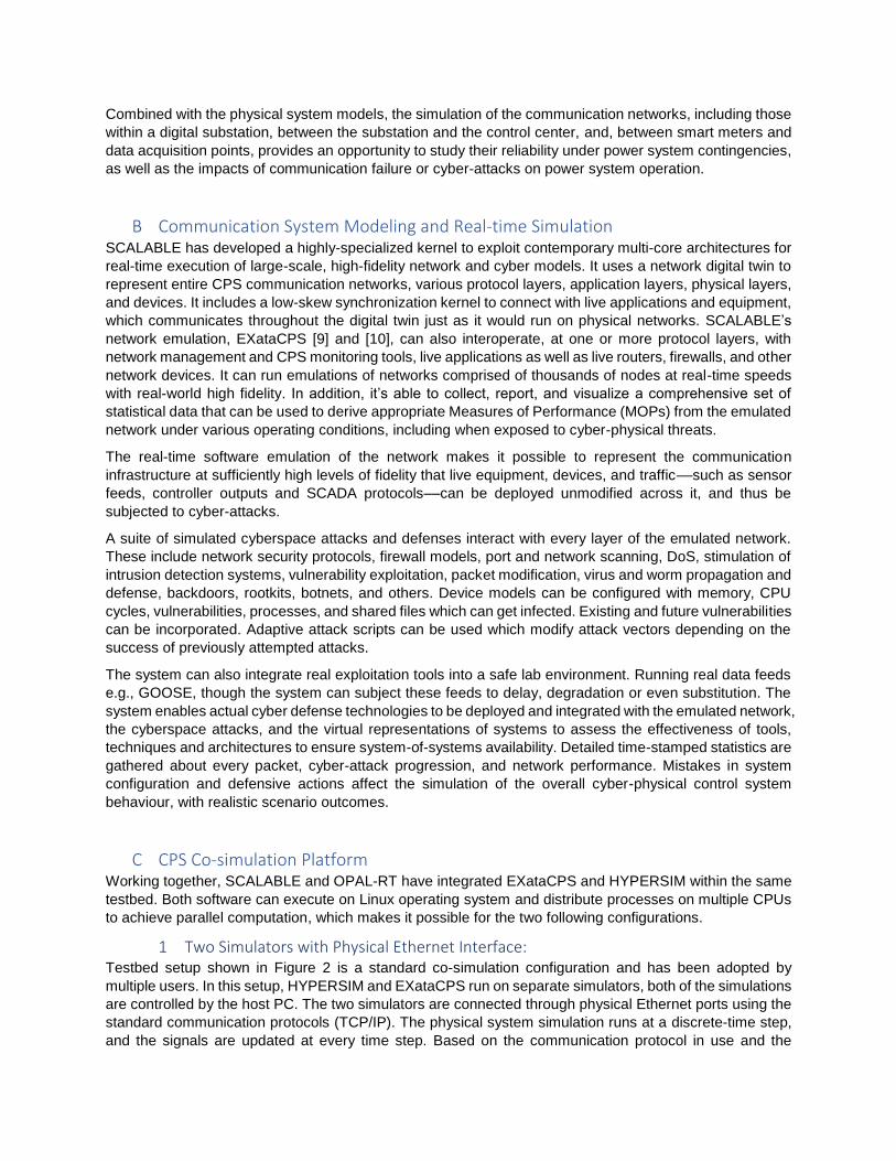
B Communication System Modeling and Real-time Simulation SCALABLE has developed a highly-specialized kernel to exploit contemporary multi-core architectures for
real-time execution of large-scale, high-fidelity network and cyber models. It uses a network digital twin to
represent entire CPS communication networks, various protocol layers, application layers, physical layers,
and devices. It includes a low-skew synchronization kernel to connect with live applications and equipment,
which communicates throughout the digital twin just as it would run on physical networks. SCALABLE’s
network emulation, EXataCPS [9] and [10], can also interoperate, at one or more protocol layers, with
network management and CPS monitoring tools, live applications as well as live routers, firewalls, and other
network devices. It can run emulations of networks comprised of thousands of nodes at real-time speeds
with real-world high fidelity. In addition, it’s able to collect, report, and visualize a comprehensive set of
statistical data that can be used to derive appropriate Measures of Performance (MOPs) from the emulated
network under various operating conditions, including when exposed to cyber-physical threats.
The real-time software emulation of the network makes it possible to represent the communication
infrastructure at sufficiently high levels of fidelity that live equipment, devices, and traffic––such as sensor
feeds, controller outputs and SCADA protocols––can be deployed unmodified across it, and thus be
subjected to cyber-attacks.
A suite of simulated cyberspace attacks and defenses interact with every layer of the emulated network.
These include network security protocols, firewall models, port and network scanning, DoS, stimulation of
intrusion detection systems, vulnerability exploitation, packet modification, virus and worm propagation and
defense, backdoors, rootkits, botnets, and others. Device models can be configured with memory, CPU
cycles, vulnerabilities, processes, and shared files which can get infected. Existing and future vulnerabilities
can be incorporated. Adaptive attack scripts can be used which modify attack vectors depending on the
success of previously attempted attacks.
The system can also integrate real exploitation tools into a safe lab environment. Running real data feeds
e.g., GOOSE, though the system can subject these feeds to delay, degradation or even substitution. The
system enables actual cyber defense technologies to be deployed and integrated with the emulated network,
the cyberspace attacks, and the virtual representations of systems to assess the effectiveness of tools,
techniques and architectures to ensure system-of-systems availability. Detailed time-stamped statistics are
gathered about every packet, cyber-attack progression, and network performance. Mistakes in system
configuration and defensive actions affect the simulation of the overall cyber-physical control system
behaviour, with realistic scenario outcomes.
C CPS Co-simulation Platform Working together, SCALABLE and OPAL-RT have integrated EXataCPS and HYPERSIM within the same
testbed. Both software can execute on Linux operating system and distribute processes on multiple CPUs
to achieve parallel computation, which makes it possible for the two following configurations.
1 Two Simulators with Physical Ethernet Interface: Testbed setup shown in Figure 2 is a standard co-simulation configuration and has been adopted by
multiple users. In this setup, HYPERSIM and EXataCPS run on separate simulators, both of the simulations
are controlled by the host PC. The two simulators are connected through physical Ethernet ports using the
standard communication protocols (TCP/IP). The physical system simulation runs at a discrete-time step,
and the signals are updated at every time step. Based on the communication protocol in use and the
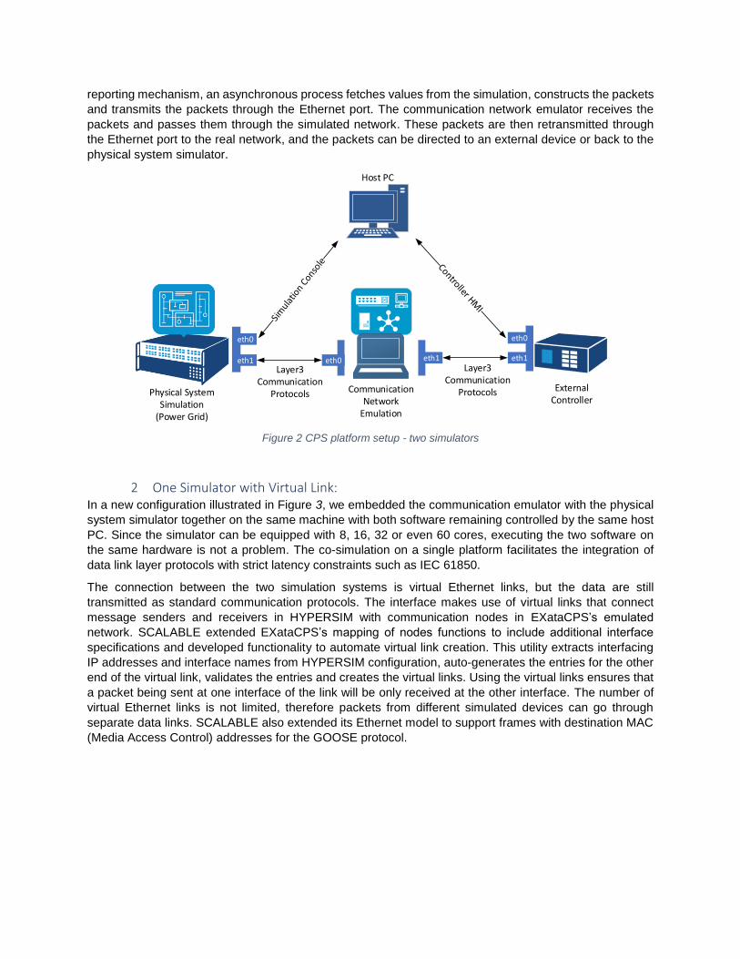
reporting mechanism, an asynchronous process fetches values from the simulation, constructs the packets
and transmits the packets through the Ethernet port. The communication network emulator receives the
packets and passes them through the simulated network. These packets are then retransmitted through
the Ethernet port to the real network, and the packets can be directed to an external device or back to the
physical system simulator.
Physical SystemSimulation
(Power Grid)
Host PC
eth0
eth1 eth0
External Controller
Communication Network
Emulation
eth1
eth0
eth1
Layer3Communication
Protocols
Layer3Communication
Protocols
Figure 2 CPS platform setup - two simulators
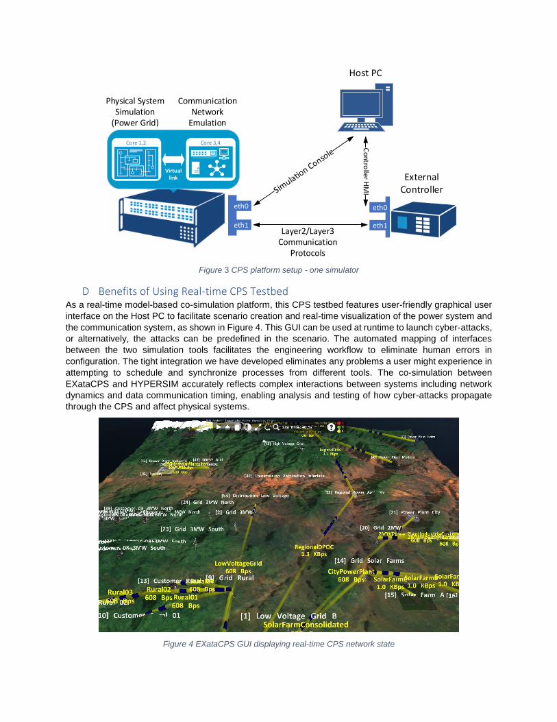
2 One Simulator with Virtual Link: In a new configuration illustrated in Figure 3, we embedded the communication emulator with the physical
system simulator together on the same machine with both software remaining controlled by the same host
PC. Since the simulator can be equipped with 8, 16, 32 or even 60 cores, executing the two software on
the same hardware is not a problem. The co-simulation on a single platform facilitates the integration of
data link layer protocols with strict latency constraints such as IEC 61850.
The connection between the two simulation systems is virtual Ethernet links, but the data are still
transmitted as standard communication protocols. The interface makes use of virtual links that connect
message senders and receivers in HYPERSIM with communication nodes in EXataCPS’s emulated
network. SCALABLE extended EXataCPS’s mapping of nodes functions to include additional interface
specifications and developed functionality to automate virtual link creation. This utility extracts interfacing
IP addresses and interface names from HYPERSIM configuration, auto-generates the entries for the other
end of the virtual link, validates the entries and creates the virtual links. Using the virtual links ensures that
a packet being sent at one interface of the link will be only received at the other interface. The number of
virtual Ethernet links is not limited, therefore packets from different simulated devices can go through
separate data links. SCALABLE also extended its Ethernet model to support frames with destination MAC
(Media Access Control) addresses for the GOOSE protocol.
Physical SystemSimulation
(Power Grid)
Host PC
eth0
eth1
External Controller
Co
ntro
ller HM
I
Core 1,2 Core 3,4
Virtuallink
Communication Network
Emulation
eth0
eth1Layer2/Layer3
CommunicationProtocols
Figure 3 CPS platform setup - one simulator
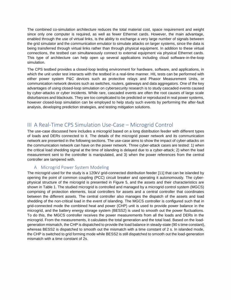
D Benefits of Using Real-time CPS Testbed As a real-time model-based co-simulation platform, this CPS testbed features user-friendly graphical user
interface on the Host PC to facilitate scenario creation and real-time visualization of the power system and
the communication system, as shown in Figure 4. This GUI can be used at runtime to launch cyber-attacks,
or alternatively, the attacks can be predefined in the scenario. The automated mapping of interfaces
between the two simulation tools facilitates the engineering workflow to eliminate human errors in
configuration. The tight integration we have developed eliminates any problems a user might experience in
attempting to schedule and synchronize processes from different tools. The co-simulation between
EXataCPS and HYPERSIM accurately reflects complex interactions between systems including network
dynamics and data communication timing, enabling analysis and testing of how cyber-attacks propagate
through the CPS and affect physical systems.
Figure 4 EXataCPS GUI displaying real-time CPS network state
The combined co-simulation architecture reduces the total material cost, space requirement and weight
since only one computer is required, as well as fewer Ethernet cards. However, the main advantage,
enabled through the use of virtual links, is the ability to exchange a very large number of signals between
the grid simulator and the communication emulator to simulate attacks on larger systems, since the data is
being transferred through virtual links rather than through physical equipment. In addition to these virtual
connections, the testbed can simultaneously connect to external equipment via physical Ethernet cards.
This type of architecture can help open up several applications including cloud software-in-the-loop
simulation.
The CPS testbed provides a closed-loop testing environment for hardware, software, and applications, in
which the unit under test interacts with the testbed in a real-time manner. HIL tests can be performed with
either power system P&C devices such as protective relays and Phasor Measurement Units, or
communication network devices such as switches, routers, gateways and data aggregators. One of the key
advantages of using closed-loop simulation on cybersecurity research is to study cascaded events caused
by cyber-attacks or cyber incidents. While rare, cascaded events are often the root causes of large scale
disturbances and blackouts. They are too complicated to be predicted or reproduced in real power systems,
however closed-loop simulation can be employed to help study such events by performing the after-fault
analysis, developing prediction strategies, and testing mitigation solutions.
III A Real-Time CPS Simulation Use-Case – Microgrid Control The use-case discussed here includes a microgrid based on a long distribution feeder with different types
of loads and DERs connected to it. The details of the microgrid power network and its communication
network are presented in the following sections. The use-case aims to show the impact of cyber-attacks on
the communication network can have on the power network. Three cyber-attack cases are tested: 1) when
the critical load shedding signal at the time of islanding is delayed due to a cyber-attack; 2) when the load
measurement sent to the controller is manipulated, and 3) when the power references from the central
controller are tampered with.
A Microgrid Power System Modeling The microgrid used for the study is a 120kV grid-connected distribution feeder [11] that can be islanded by
opening the point of common coupling (PCC) circuit breaker and operating it autonomously. The cyber-
physical structure of the microgrid is presented in Figure 5, and the assets and their characteristics are
shown in Table 1. The studied microgrid is controlled and managed by a microgrid control system (MGCS)
comprising of protection elements, local controllers for assets and a central controller that coordinates
between the different assets. The central controller also manages the dispatch of the assets and load
shedding of the non-critical load in the event of islanding. The MGCS controller is configured such that in
grid-connected mode the combined heat and power (CHP) unit is used to provide power balance in the
microgrid, and the battery energy storage system (BESS2) is used to smooth out the power fluctuations.
To do this, the MGCS controller receives the power measurements from all the loads and DERs in the
microgrid. From the measurements, it calculates the total generation and the total load. Based on the load-
generation mismatch, the CHP is dispatched to provide the load balance in steady-state (90 s time constant),
whereas BESS2 is dispatched to smooth out the mismatch with a time constant of 2 s. In islanded mode,
the CHP is switched to grid forming mode while BESS2 is still dispatched to smooth out the load-generation
mismatch with a time constant of 2s.

Figure 5 Cyber-physical structure of the Microgrid
Table 1 Microgrid assets and loads
Asset Type Ratings Operation Modes
Loads
Load 1 Critical 4MW Always connected
Load 2 Critical 4MW Always connected
Load 3 Hybrid 4MW Can be disconnected on second
priority
Load 4 Non-Critical 3MW To be disconnected in Islanded mode
Distributed Energy Resources (DERs)
Combined Heat and Power (CHP) plant
Gas Turbine 10MW P/Q (Grid-connected)
V/f (Grid forming)
2 x PV Generation System
With Smoothing Battery Energy Storage System
1.5MVA + 0.5MVA (1.2MWh)
MPPT with smoothing battery
Battery Energy Storage System (BESS)
Lead Acid 1MW (5MWh) Power smoothing
The microgrid has the capability to island where the CHP is switched to grid forming mode as soon as the
central controller gets the island information from the MGCS. It comprises four lumped loads, out of which
two are critical loads. These loads are always served whether the microgrid is in grid-connected mode or
islanded mode. Load 4 is shed as soon as the MGCS gets the status from the PCC breaker that it has
islanded. Load 3 is only shed in emergency conditions in the islanded mode. For the studies in this paper,
the emergency condition is defined as the event when generation is less than the load by at least 3MW.
For the stability of the system, the communication link between the sheddable load (Load 4), the central
controller and the MGCS are critical. As the microgrid islands, load 4 should be shed as soon as possible,
otherwise the frequency continues to fall, and may cause the other DERs and loads to trip due to being
under frequency.
Microgrid controller
Switch
Utility
SC level: 100MVAX/R: 7
T1
15 MVA120 / 25 kV
BESS3
PV
T2 T4
CHP
T3
BESS2
3 MVA0.48 / 25 kV
2.4 MVA0.48 / 25 kV
10 MVA25 / 2.4 kV
1 MVA0.48kV
10 MVA2.4kV
0.5 MVA0.48 kV
1.5 MVA0.48 kV
PV
BESS1
T5
10.3 MVA25 / 0.575 kV
1.5 MVA0.575 kV
0.5 MVA0.575 kV
PCC
Load 1 Load 2 Load 3
Load 4
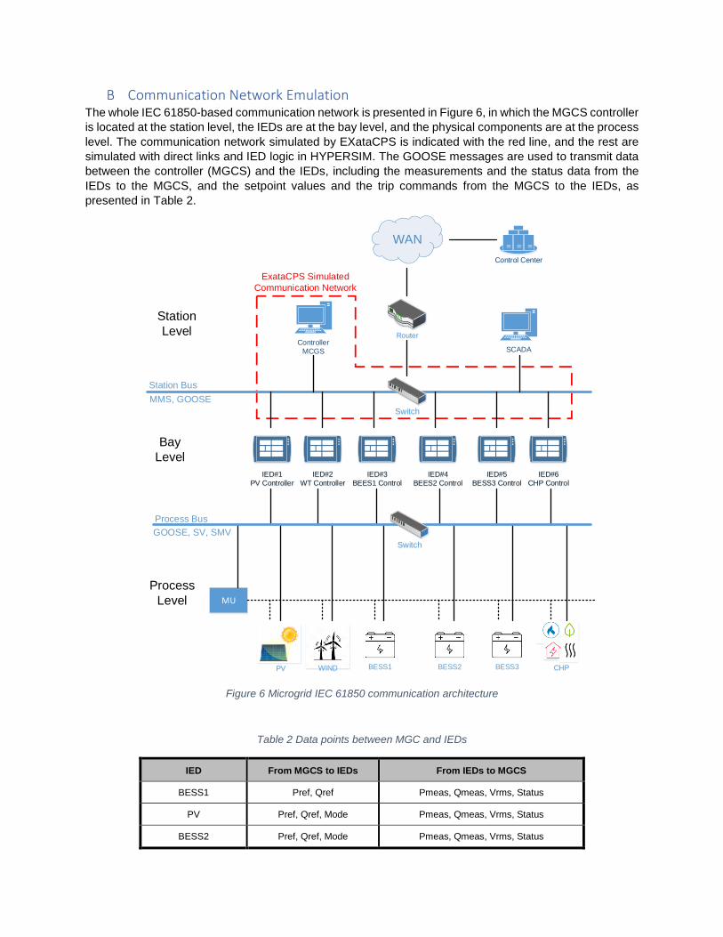
B Communication Network Emulation The whole IEC 61850-based communication network is presented in Figure 6, in which the MGCS controller
is located at the station level, the IEDs are at the bay level, and the physical components are at the process
level. The communication network simulated by EXataCPS is indicated with the red line, and the rest are
simulated with direct links and IED logic in HYPERSIM. The GOOSE messages are used to transmit data
between the controller (MGCS) and the IEDs, including the measurements and the status data from the
IEDs to the MGCS, and the setpoint values and the trip commands from the MGCS to the IEDs, as
presented in Table 2.
MU
Process Bus
GOOSE, SV, SMV
WINDPV
Station Bus
MMS, GOOSE
BESS3 CHP
IED#1
PV Controller
IED#2
WT Controller
Switch
IED#3
BEES1 Control
IED#4
BEES2 Control
IED#5
BESS3 Control
IED#6
CHP Control
Switch
Process
Level
Bay
Level
Station
LevelController
MCGS
Control Center
Router
WAN
SCADA
BESS2BESS1
ExataCPS Simulated
Communication Network
Figure 6 Microgrid IEC 61850 communication architecture
Table 2 Data points between MGC and IEDs
IED From MGCS to IEDs From IEDs to MGCS
BESS1 Pref, Qref Pmeas, Qmeas, Vrms, Status
PV Pref, Qref, Mode Pmeas, Qmeas, Vrms, Status
BESS2 Pref, Qref, Mode Pmeas, Qmeas, Vrms, Status
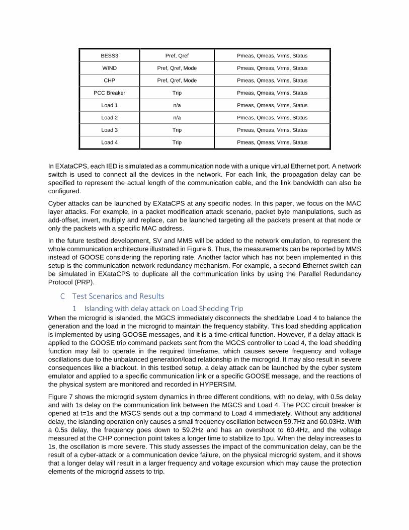
BESS3 Pref, Qref Pmeas, Qmeas, Vrms, Status
WIND Pref, Qref, Mode Pmeas, Qmeas, Vrms, Status
CHP Pref, Qref, Mode Pmeas, Qmeas, Vrms, Status
PCC Breaker Trip Pmeas, Qmeas, Vrms, Status
Load 1 n/a Pmeas, Qmeas, Vrms, Status
Load 2 n/a Pmeas, Qmeas, Vrms, Status
Load 3 Trip Pmeas, Qmeas, Vrms, Status
Load 4 Trip Pmeas, Qmeas, Vrms, Status
In EXataCPS, each IED is simulated as a communication node with a unique virtual Ethernet port. A network
switch is used to connect all the devices in the network. For each link, the propagation delay can be
specified to represent the actual length of the communication cable, and the link bandwidth can also be
configured.
Cyber attacks can be launched by EXataCPS at any specific nodes. In this paper, we focus on the MAC
layer attacks. For example, in a packet modification attack scenario, packet byte manipulations, such as
add-offset, invert, multiply and replace, can be launched targeting all the packets present at that node or
only the packets with a specific MAC address.
In the future testbed development, SV and MMS will be added to the network emulation, to represent the
whole communication architecture illustrated in Figure 6. Thus, the measurements can be reported by MMS
instead of GOOSE considering the reporting rate. Another factor which has not been implemented in this
setup is the communication network redundancy mechanism. For example, a second Ethernet switch can
be simulated in EXataCPS to duplicate all the communication links by using the Parallel Redundancy
Protocol (PRP).
C Test Scenarios and Results
1 Islanding with delay attack on Load Shedding Trip When the microgrid is islanded, the MGCS immediately disconnects the sheddable Load 4 to balance the
generation and the load in the microgrid to maintain the frequency stability. This load shedding application
is implemented by using GOOSE messages, and it is a time-critical function. However, if a delay attack is
applied to the GOOSE trip command packets sent from the MGCS controller to Load 4, the load shedding
function may fail to operate in the required timeframe, which causes severe frequency and voltage
oscillations due to the unbalanced generation/load relationship in the microgrid. It may also result in severe
consequences like a blackout. In this testbed setup, a delay attack can be launched by the cyber system
emulator and applied to a specific communication link or a specific GOOSE message, and the reactions of
the physical system are monitored and recorded in HYPERSIM.
Figure 7 shows the microgrid system dynamics in three different conditions, with no delay, with 0.5s delay
and with 1s delay on the communication link between the MGCS and Load 4. The PCC circuit breaker is
opened at t=1s and the MGCS sends out a trip command to Load 4 immediately. Without any additional
delay, the islanding operation only causes a small frequency oscillation between 59.7Hz and 60.03Hz. With
a 0.5s delay, the frequency goes down to 59.2Hz and has an overshoot to 60.4Hz, and the voltage
measured at the CHP connection point takes a longer time to stabilize to 1pu. When the delay increases to
1s, the oscillation is more severe. This study assesses the impact of the communication delay, can be the
result of a cyber-attack or a communication device failure, on the physical microgrid system, and it shows
that a longer delay will result in a larger frequency and voltage excursion which may cause the protection
elements of the microgrid assets to trip.

Figure 7 Microgrid dynamics under packet delay attack
2 Power balance with packet manipulation on measured data In the islanded mode, the MGCS controller sends out set points to each controllable DER to balance the
loads based on the power measurement data sent from each load by GOOSE. If the data from the load is
manipulated, the MGCS may take wrong actions. In this test scenario, the active power measurement from
Load 2 is modified to a different value by applying a packet manipulation attack to the GOOSE message.
The packet manipulation is implemented with a multiplication of byte 113 and 114 by 2 in the packet starting
from t=8.2s. As shown in Figure 8, due to the byte multiplication, the Load 2 active power measurement
received by the MCGS controller is modified to wrong values which are a double of the true measurement
values. This manipulation makes the MGCS controller perceive the total load to be higher than the total
generation by 3MW, therefore a trip command is issued to disconnect Load 3. In addition to this false
tripping, it also causes voltage and frequency variations in the microgrid.
Figure 8 Microgrid dynamics under packet manipulation attack - multiplication

3 Power balance with packet manipulation on set points In the islanded mode, the MGCS controller sets the active power set point of the Battery Energy Storage
System (BESS2) to smooth out the variations in the loads such that its mean is around 0 (this reduces the
ramping requirements on the CHP). In this scenario, the reference set point sent by the MGCS controller
to BESS2 is manipulated by adding an offset value of 20 to byte 129 and 130. This forces the BESS2 to
generate more than required, which causes the MGCS controller to update its BESS2 setpoint to a different
value adjusting to the actual power measured from BESS2. Since the updated power reference is again
manipulated, the MGCS controller updates the setpoint again. A successive recursion of this event causes
the MGCS controller to produce highly varying setpoints for BESS2. Therefore, the attack causes the set
point to vary between positive and negative values and sometimes the values are higher than 1 pu. Since
BESS2 has a fast response, the frequent variations in active power output cause fluctuations in the voltage
and frequency, as can be noticed from Figure 9.
A further analysis of the time-domain voltage measurement taken at the CHP connection point shows that
the voltage varies in an eight times wider envelope during the packet manipulation attack as shown in
Figure 10. In addition to the voltage variation, the frequency variation is also higher than what would
conventionally be expected in a distribution system.
Figure 9 Microgrid dynamics under packet modification attack - add offset
Figure 10 Voltage (pu) of phase A voltage at CHP point of connection

IV Conclusions
This paper presents a real-time co-simulation CPS testbed with two simulation software running on the
same hardware simulator. A seamless and scalable integration of the CPS testing environment is achieved
by using virtual links between the two systems. We have presented a proof-of-concept co-simulation
involving a microgrid system simulated in HYPERSIM and an IEC 61850 station bus network simulated in
EXataCPS. Cyber-attacks targeting IEC 61850 GOOSE messages, including packet delay insertion and
message payload modification, were launched from EXataCPS, and the impacts on the physical system
were monitored and analyzed in HYPERSIM.
Some of the benefits of our co-simulation solution are:
• Integration of emulated network with equipment and physical system dynamics simulation.
• Packet-level emulation to predict system behavior under attack.
• Scalability to represent the entire network while respecting timing constraints.
• Ability to run ‘what-if’ scenarios of control systems under cyber-attack without threatening
operations.
• Assessment of the effectiveness of tools, techniques, and architectures to ensure system
availability.
• Measurement and improvement of system resiliency, and develop plans to mitigate risks from
cyber-attacks.
• Packaging of EXataCPS and HYPERSIM on the same platform enables fast communication at
Layer 2, ensuring that the timing constraints of the overall system are met.
While the scenarios presented in this paper serve as a proof-of-concept of our CPS co-simulation testbed,
its real value lies in emulating the complex dynamics of new applications and control systems on smart
grids, along with the connection points, cyber vulnerabilities and dynamic performance of the networks that
enable them. Successful cyber-attacks usually manifest themselves through Internet connections on the IT
network, spear-phishing with malware attachments, propagation through the IT network, stealing of
credentials, improper firewall configuration, access to the OT network, manipulation of signals or breakers
etc. This type of CPS testbed will enable actual cyber defense technologies to be deployed and integrated
with the emulated network and physical system dynamics undergoing complex cyber-attack sequences for
the accurate evaluation of system-of-systems resiliency.
V Bibliography
[1] G. Ericsson, "Cyber Security and Power System Communication—Essential Parts of a Smart Grid
Infrastructure," IEEE Transactions on Power Delivery, vol. 25, no. 3, pp. 1501 - 1507, April 2010.
[2] A. Hahn, A. Ashok, S. Sridhar and M. Govindarasu, "Cyber-physical security testbeds: architecture,
application, and evaluation for smart grid," IEEE Transaction on Smart Grid, vol. 4, no. 2, pp. 847-
855, June 2013.
[3] Y. Yang, H. Jiang, M. K, L. Gao, Y. Yuan, W. Huang and S. Sezer, "Cybersecurity test-bed for IEC
61850 based smart substations," in IEEE Power & Energy Society General Meeting, Denver, CO,
2015.
[4] M. Chlela, G. Joos, M. Kassouf and Y. Brissette, "Real-time testing platform for microgrid controllers
against false data injection cybersecurity attacks," in 2016 IEEE Power and Energy Society General
Meeting (PESGM), Boston, MA, USA, July 2016.

[5] J. Hong, R. Nuqui, A. Kondabathini and D. Ishchenko, "Cyber Attack Resilient Distance Protection
and Circuit Breaker Control for Digital Substations," IEEE Transactions on Industrial Informatics, vol.
15, no. 7, pp. 4332-4341, 2019.
[6] J. Blanger, P. Venne and J.-N. Paquin, "The what where and why of real-time simulation," in 2010
IEEE PES General Meeting, Detroit, 2010.
[7] A. Haddadi, J. Mahseredjian, H. Hooshyar, L. Vanfretti and C. Dufour, "An active distribution network
model for smart grid control and protection studies—Model validation progress," in 2017 IEEE
Electrical Power and Energy Conference (EPEC), Saskatoon, 2017.
[8] H. Hooshyar, L. Vanfretti and C. Dufour, "Delay-free parallelization for real-time simulation of a large
active distribution grid model," in IECON 2016 - 42nd Annual Conference of the IEEE Industrial
Electronics Society, Florence, 2016.
[9] L. Wihl and M. Varshney, "A Virtual Cyber Range for Cyber Warfare Analysis and Training," in The
Interservice/Industry Training, Simulation and Education Conference (I/ITSEC), Orlando, FL, 2012.
[10] H. Duong, R. Bagrodia, S. Dietz and B. Salisbury, "Assessing Cyber Resilience of Military Systems
Using LVC Models," in The Interservice/Industry Training, Simulation and Education Conference
(I/ITSEC), Orlando, FL, 2018.
[11] D. Zhuang, Master Thesis: Real time testing of intelligent relays for synchronous distributed
generation islanding detection, Montreal, Canada: McGill University, 2012.