I Bags With Grounding NSTALLATION...
7
I NSTALLATION I NSTRUCTIONS Proper installation of bags and cages is required to ensure that the metal cages are not isolated from ground with the tubesheet (cell plate) in applications that have potential for an explosion hazard. WARNING: The effectiveness of a grounding mechanism depends upon proper installation and connection of the grounding mechanism to an adequately grounded collector component. Failure to properly install and connect grounding mechanism or maintain grounding of the collector component may result in static electricity discharge and possible explosion of dust stream within the collector and serious property damage and/or bodily injury. Proper installation must be verified per Section B of these instructions prior to operating collector. SECTION A: BAG INSTALLATION Bottom Load Collectors The two grounding straps at the top of the bag are intended to ground the cage and clamp to the metal bag cup/ venturi. Ensure that the bag cup/venturi is cleaned to remove dust and corrosion buildup. Position the cage in the bag so that the split in the cage top is located at 90 degrees from the seam on the bag. This will ensure that both grounding straps will not be located in between the split. Tuck the bag top into the cage top and install bag, cage, and clamp per equipment manufacturer’s guidelines. WARNING: If bag cup/venturi is plastic, bag must be designed with different ground wire that can be attached to grounding bolt or stud. Top Load Collectors with Snapband Bags The two grounding straps at the top of the bag are intended to ground the cage to the tubesheet. Ensure that the hole is cleaned to remove dust and corrosion buildup. Install bag in hole and insert cage. Bags With Grounding Straps for Grounding Metal Cages -continued- Grounding strap Grounding strap Grounding strap Grounding strap Grounding strap
Transcript of I Bags With Grounding NSTALLATION...
IN S T A L L A T I O N IN S T R U C T I O N S
Proper installation of bags and cages is required to ensure that the metal cages are not isolated from ground with the tubesheet (cell plate) in applications that have potential for an explosion hazard.
WARNING: The effectiveness of a grounding mechanism depends upon proper installation and connection of the grounding mechanism to an adequately grounded collector component. Failure to properly install and connect grounding mechanism or maintain grounding of the collector component may result in static electricity discharge and possible explosion of dust stream within the collector and serious property damage and/or bodily injury. Proper installation must be verified per Section B of these instructions prior to operating collector.
SECTION A: BAG INSTALLATION
Bottom Load Collectors
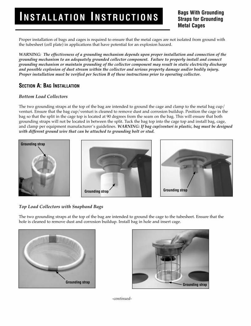
The two grounding straps at the top of the bag are intended to ground the cage and clamp to the metal bag cup/venturi. Ensure that the bag cup/venturi is cleaned to remove dust and corrosion buildup. Position the cage in the bag so that the split in the cage top is located at 90 degrees from the seam on the bag. This will ensure that both grounding straps will not be located in between the split. Tuck the bag top into the cage top and install bag, cage, and clamp per equipment manufacturer’s guidelines. WARNING: If bag cup/venturi is plastic, bag must be designed with different ground wire that can be attached to grounding bolt or stud.
Top Load Collectors with Snapband Bags
The two grounding straps at the top of the bag are intended to ground the cage to the tubesheet. Ensure that the hole is cleaned to remove dust and corrosion buildup. Install bag in hole and insert cage.
Bags With Grounding Straps for Grounding Metal Cages
-continued-
Grounding strap
Grounding strap Grounding strap
Grounding strapGrounding strap
INSTRUCCIONES DE INSTALACIÓN
Es fundamental lograr una correcta instalación de las bolsas (mangas) filtrantes y las jaulas (o canastillas) y verificar que las jaulas metálicas están conectadas a tierra por contacto con el espejo (o placa portamangas) en aquellas aplica-ciones en las que exista riesgo de explosiones.
ATENCIÓN: La efectividad de un mecanismo de puesta a tierra dependerá de una instalación adecuada y del enlace eficaz entre el mecanismo de puesta a tierra y el componente del colector de polvo con conexión a tierra. Fallos en la instalación y conexión del mecanismo a tierra o en la verificación de una buena conexión a tierra del compo-nente del colector de polvo podrían ocasionar descargas de electricidad estática y riesgo de explosión en el interior del colector que podrían ocasionar serios daños materiales y/o daños a las personas. La correcta instalación de la puesta a tierra deberá cotejarse con la Sección B de estas instrucciones antes de poner el colector en funcionamiento.
SECCIÓN A: INSTALACION DE MANGAS
Colectores de Acceso Inferior
Las dos bandas para conexión a tierra que se encuentran en el extremo superior de las mangas filtrantes (bolsas filtrantes) cumplen la función de conectar a tierra la jaula y la abrazadera a la cazoleta/venturi. Asegúrese de que la cazoleta y el venturi están limpios, libres de polvo y corrosión. Ubique la jaula en la manga filtrante de manera tal que la hendidura de la parte superior de la jaula se encuentre a 90º de la costura de la bolsa. Esto asegurará que nin-guna de las bandas de sujeción se insertará en la hendidura. Doble el borde superior de la bolsa filtrante y colóquelo en el interior de la jaula; luego instale la bolsa, la jaula y la abrazadera siguiendo las instrucciones del manual del fabricante del equipo. ATENCION: Si la cazoleta y el venturi fueran de plástico, las mangas filtrantes deberán estar diseñadas con un alambre a tierra diferente para que pueda ser sujetado al tornillo o perno con conexión a
tierra.
Colectores de Acceso Superior con Mangas Filtrantes con Snapband (Banda de Compresión)
La función de ambas bandas para conexión a tierra ubicadas en la parte superior de la manga es la de conectar la jaula a tierra a través de su contacto con el espejo (o placa portamangas). Asegúrese de limpiar el orificio de la placa
Mangas Filtrantes con Bandas de Conexión a Tierra para Jaulas Metálicas
- continúa en la página siguiente -
Banda de Conexión a Tierra
Banda de Conexión a Tierra
Banda de Conexión a Tierra
Banda de Conexión a Tierra
Banda de Conexión a Tierra

Top Load Collectors with Flange Top or Ring Top Bags
The two grounding straps at the top of the bag are intended to provide a grounding path between the cage and the tubesheet in addition to any ground achieved using the hold-downs. Ensure that the top surface of the tubesheet is cleaned to remove dust and corrosion buildup. Install bag/cage per equipment manufacturer’s guidelines.
SECTION B: VERIFICATION OF PROPER GROUNDING
Proper installation must be confirmed by testing to verify 1x10⁶ (1 megohm) maximum resistance at 500 volts between cage and tubesheet (cell plate).
In addition to the proper installation and grounding of bags and cages, the end user should select an appropriate filter media for use in bags. Refer to the National Fire Protection Association (NFPA) “Recommended Practice on Static Electricity,” NFPA 77-2000 edition for more information (www.nfpa.org).
K6MK1780 P/N 1001322 02/02/04
Grounding strap Grounding strap
Bottom load collector: testing resistance between cage and tubesheet.
Top load collector: testing resistance between cage and tubesheet.
Colectores de Acceso Superior con Mangas con Brida o Anillo Superior
La función de las dos bandas para conexión a tierra localizadas en la parte superior de las bolsas filtrantes es la de proporcionar una vía a tierra entre la jaula y el espejo además de la puesta a tierra lograda con la utilización de pernos de sujeción (hold-downs). Asegúrese de que la superficie superior del espejo esté perfectamente limpia para evitar la acumulación de polvo y evitar corrosión. Instale la bolsa y la jaula siguiendo las indicaciones del fabricante del equipo.
SECCION B: VERIFICACION DE PUESTA A TIERRA ADECUADA
La instalación adecuada debe confirmarse a través de una prueba de verificación de resistencia máxima de 1 x 10⁶
(1 megohmios) a 500 voltios entre la jaula y el espejo (placa portamangas).
Además de la instalación y la conexión a tierra correcta de las bolsas filtrantes y de las jaulas, el usuario deberá seleccionar un medio filtrante adecuado para las mangas. Consultar con la Asociación Nacional de Protección con tra Incendios (NFPA) de los Estados Unidos de América sobre “Prácticas Recomendadas para Electricidad Estática” (“Recommended Practice on Static Electricity”) NFPA 77-2000, para mayor información visitar la página web www.nfpa.org.
K6MK1780 P/N 1001322 02/02/04
Colector de polvo de acceso inferior: prueba de resistencia entre la jaula y el espejo.
Colector de acceso superior: prueba de resistencia entre la jaula y el espejo.
Banda de Conexión a Tierra
Banda de Conexión a Tierra