Hydrous Manganese Dioxide Nanowall Arrays Growth and Their Li Ions
5
Hydrous Manganese Dioxide Nanowall Arrays Growth and Their Li + Ions Intercalation Electrochemical Properties Dawei Liu, † Qifeng Zhang, † Peng Xiao, †,⊥ Betzaida B. Garcia, † Qing Guo, ‡ Richard Champion, § and Guozhong Cao* ,† Department of Materials Science and Engineering, Department of Mechanical Engineering, and Department of Chemical Engineering, UniVersity of Washington, Seattle, Washington 98195, and Department of Physics, Chongqing UniVersity, P. R. China ReceiVed July 26, 2007. ReVised Manuscript ReceiVed NoVember 13, 2007 Nanowall arrays of hydrous manganese dioxide MnO 2 · 0.5H 2 O were deposited on cathodic substrates by the potentiostatic method from a mixed aqueous solution of manganese acetate and sodium sulfate, and the Li + ions intercalation properties of such nanowall arrays were studied. The deposition was induced by a change of local pH resulting from electrolysis of H 2 O. Composition of this new nanowall structure was investigated by means of combined XRD, XPS, and TGA and determined to be hydrous manganese dioxide. SEM study revealed that the MnO 2 · 0.5H 2 O nanowall arrays were homogeneous across the entire substrate of top thicknesses that varied from 50 to 100 nm with identical depth. The nanowall arrays of hydrous manganese dioxide exhibited an initial capacity of 270 mAh/g with a reversible capacity maintained at 220 mAh/g at the 50th charge/discharge cycle in the Li + ions intercalation capacity measurement at a high charge/discharge rate of 0.1 mA/cm 2 (C/2, 76 mAh/g). This greatly enhanced Li + ions intercalation capacity is ascribed to the large active surface area of the nanowall arrays and a short facile diffusion path for Li + ions. The nanowall arrays of hydrous manganese dioxide also displayed an improved cyclic stability attributed to the reduced strain accumulated in these nanostructures during Li + ions intercalation. 1. Introduction Manganese dioxide has long been a favorable candidate for the applications in electronic devices, such as superca- pacitors 1 and Zn/MnO 2 batteries, 2 due to its low cost and limited environmental impact. 3 Because of these advantages, manganese dioxide is considered to be one of the best cathode materials for Li + ions batteries. However, compared to other transition metal oxides, such as vanadium pentoxide whose films can deliver a discharge capacity of up to 300 mAh/g, 4 the films of manganese dioxide deliver a typically lower discharge capacity of <120 mAh/g. 5 This shortfall in capacity limits its potential application in Li + ions batteries. Several methods to improve the Li + ions capacity have been explored. 6,7 One major effort has been to increase the active surface area of manganese dioxide and, thus, allow for a short facile solid-state diffusion path for Li + ions. 8 Ap- propriately fabricated nanostructures would satisfy such requirements and thus offer much enhanced Li + ions intercalation capability and improved charge/discharge kinet- ics. Wang et al. have shown that nanorod, nanotube, and nanocable arrays of vanadium pentoxide exhibited a signifi- cantly higher discharge capacity than V 2 O 5 films. 9,10 Nano- rods or nanowires of manganese dioxide have also been fabricated by template-based sol–gel 11 and electrochemical deposition 12,13 methods with enhanced Li + ions intercalation properties compared with bulk films. In addition, since hydrous manganese dioxide has been studied for capacitor applications, 14 amorphous films of hydrous manganese dioxide were also investigated in Li + ions battery applica- tions 15 to improve the charge/discharge cyclic stability. Template-based nanowires of hydrous manganese dioxide * To whom correspondence should be addressed. E-mail: gzcao@ u.washington.edu. † Department of Materials Science and Engineering, University of Washington. ‡ Department of Mechanical Engineering, University of Washington. § Department of Chemical Engineering, University of Washington. ⊥ Chongqing University. (1) Reddy, R. N.; Reddy, R. G. J. Power Sources 2004, 132, 315. (2) Minakshi, M.; Singh, P.; Issa, T. B.; Thurgate, S.; Marco, R. D. J. Power Sources 2006, 153, 165. (3) Johnson, C. S. J. Power Sources 2007, 165, 559. (4) Wang, Y.; Cao, G. Z. Electrochim. Acta 2006, 51, 4865. (5) Johnson, C. S.; Dees, D. W.; Mansuetto, M. F.; Thackeray, M. M.; Vissers, D. R.; Argriyou, D.; Loong, C. K.; Christensen, L. J. Power Sources 1997, 68, 570. (6) Piffard, Y.; Leroux, F.; Guyomard, D.; Mansot, J. L.; Tournoux, M. J. Power Sources 1997, 68, 698. (7) Chuang, P. Y.; Hu, Ch. Mater. Chem. Phys. 2005, 92, 138. (8) Long, J. W.; Dunn, B.; Rolison, D. R.; White, H. S. Chem. ReV. 2004, 104, 4463. (9) Wang, Y.; Takahashi, K.; Shang, H. M.; Lee, K. H.; Cao, G. Z. J. Phys. Chem. B 2005, 109, 3085. (10) Wang, Y.; Cao, G. Z. Chem. Mater. 2006, 18, 2787. (11) Sugantha, M.; Ramakrishnan, P. A.; Hermann, A. M.; Warmsingh, C. P.; Ginley, D. S. Int. J. Hydrogen Energy 2003, 28, 597. (12) Xu, C. L.; Bao, S. J.; Kong, L. B.; Li, H.; Li, H. L. J. Solid State Chem. 2006, 179, 1351. (13) Hill, L. L.; Verbaere, A.; Guyomard, D. J. Electrochem. Soc. 2003, 150, 135. (14) Zhou, Y. K.; He, B. L.; Zhang, F. B.; Li, H. L. J. Solid State Electrochem. 2004, 8, 482. (15) Chiu, K. F.; Lin, H. C.; Lin, K. M.; Chen, C. C. J. Electrochem. Soc. 2006, 153, A1992. 1376 Chem. Mater. 2008, 20, 1376–1380 10.1021/cm702033z CCC: $40.75 2008 American Chemical Society Published on Web 01/10/2008
Transcript of Hydrous Manganese Dioxide Nanowall Arrays Growth and Their Li Ions
Hydrous Manganese Dioxide Nanowall Arrays Growth and TheirLi+ Ions Intercalation Electrochemical Properties
Dawei Liu,† Qifeng Zhang,† Peng Xiao,†,⊥ Betzaida B. Garcia,† Qing Guo,‡
Richard Champion,§ and Guozhong Cao*,†
Department of Materials Science and Engineering, Department of Mechanical Engineering, andDepartment of Chemical Engineering, UniVersity of Washington, Seattle, Washington 98195, and
Department of Physics, Chongqing UniVersity, P. R. China
ReceiVed July 26, 2007. ReVised Manuscript ReceiVed NoVember 13, 2007
Nanowall arrays of hydrous manganese dioxide MnO2 ·0.5H2O were deposited on cathodic substratesby the potentiostatic method from a mixed aqueous solution of manganese acetate and sodium sulfate,and the Li+ ions intercalation properties of such nanowall arrays were studied. The deposition was inducedby a change of local pH resulting from electrolysis of H2O. Composition of this new nanowall structurewas investigated by means of combined XRD, XPS, and TGA and determined to be hydrous manganesedioxide. SEM study revealed that the MnO2 ·0.5H2O nanowall arrays were homogeneous across the entiresubstrate of top thicknesses that varied from 50 to 100 nm with identical depth. The nanowall arrays ofhydrous manganese dioxide exhibited an initial capacity of 270 mAh/g with a reversible capacitymaintained at 220 mAh/g at the 50th charge/discharge cycle in the Li+ ions intercalation capacitymeasurement at a high charge/discharge rate of 0.1 mA/cm2 (C/2, 76 mAh/g). This greatly enhanced Li+
ions intercalation capacity is ascribed to the large active surface area of the nanowall arrays and a shortfacile diffusion path for Li+ ions. The nanowall arrays of hydrous manganese dioxide also displayed animproved cyclic stability attributed to the reduced strain accumulated in these nanostructures during Li+
ions intercalation.
1. Introduction
Manganese dioxide has long been a favorable candidatefor the applications in electronic devices, such as superca-pacitors1 and Zn/MnO2 batteries,2 due to its low cost andlimited environmental impact.3 Because of these advantages,manganese dioxide is considered to be one of the bestcathode materials for Li+ ions batteries. However, comparedto other transition metal oxides, such as vanadium pentoxidewhose films can deliver a discharge capacity of up to 300mAh/g,4 the films of manganese dioxide deliver a typicallylower discharge capacity of <120 mAh/g.5 This shortfall incapacity limits its potential application in Li+ ions batteries.Several methods to improve the Li+ ions capacity have beenexplored.6,7 One major effort has been to increase the activesurface area of manganese dioxide and, thus, allow for a
short facile solid-state diffusion path for Li+ ions.8 Ap-propriately fabricated nanostructures would satisfy suchrequirements and thus offer much enhanced Li+ ionsintercalation capability and improved charge/discharge kinet-ics. Wang et al. have shown that nanorod, nanotube, andnanocable arrays of vanadium pentoxide exhibited a signifi-cantly higher discharge capacity than V2O5 films.9,10 Nano-rods or nanowires of manganese dioxide have also beenfabricated by template-based sol–gel11 and electrochemicaldeposition12,13 methods with enhanced Li+ ions intercalationproperties compared with bulk films. In addition, sincehydrous manganese dioxide has been studied for capacitorapplications,14 amorphous films of hydrous manganesedioxide were also investigated in Li+ ions battery applica-tions15 to improve the charge/discharge cyclic stability.Template-based nanowires of hydrous manganese dioxide
* To whom correspondence should be addressed. E-mail: [email protected].
† Department of Materials Science and Engineering, University of Washington.‡ Department of Mechanical Engineering, University of Washington.§ Department of Chemical Engineering, University of Washington.⊥ Chongqing University.
(1) Reddy, R. N.; Reddy, R. G. J. Power Sources 2004, 132, 315.(2) Minakshi, M.; Singh, P.; Issa, T. B.; Thurgate, S.; Marco, R. D. J.
Power Sources 2006, 153, 165.(3) Johnson, C. S. J. Power Sources 2007, 165, 559.(4) Wang, Y.; Cao, G. Z. Electrochim. Acta 2006, 51, 4865.(5) Johnson, C. S.; Dees, D. W.; Mansuetto, M. F.; Thackeray, M. M.;
Vissers, D. R.; Argriyou, D.; Loong, C. K.; Christensen, L. J. PowerSources 1997, 68, 570.
(6) Piffard, Y.; Leroux, F.; Guyomard, D.; Mansot, J. L.; Tournoux, M.J. Power Sources 1997, 68, 698.
(7) Chuang, P. Y.; Hu, Ch. Mater. Chem. Phys. 2005, 92, 138.
(8) Long, J. W.; Dunn, B.; Rolison, D. R.; White, H. S. Chem. ReV. 2004,104, 4463.
(9) Wang, Y.; Takahashi, K.; Shang, H. M.; Lee, K. H.; Cao, G. Z. J.Phys. Chem. B 2005, 109, 3085.
(10) Wang, Y.; Cao, G. Z. Chem. Mater. 2006, 18, 2787.(11) Sugantha, M.; Ramakrishnan, P. A.; Hermann, A. M.; Warmsingh,
C. P.; Ginley, D. S. Int. J. Hydrogen Energy 2003, 28, 597.(12) Xu, C. L.; Bao, S. J.; Kong, L. B.; Li, H.; Li, H. L. J. Solid State
Chem. 2006, 179, 1351.(13) Hill, L. L.; Verbaere, A.; Guyomard, D. J. Electrochem. Soc. 2003,
150, 135.(14) Zhou, Y. K.; He, B. L.; Zhang, F. B.; Li, H. L. J. Solid State
Electrochem. 2004, 8, 482.(15) Chiu, K. F.; Lin, H. C.; Lin, K. M.; Chen, C. C. J. Electrochem. Soc.
2006, 153, A1992.
1376 Chem. Mater. 2008, 20, 1376–1380
10.1021/cm702033z CCC: $40.75 2008 American Chemical SocietyPublished on Web 01/10/2008

also demonstrated an initial capacity of 300 mAh/g;16
however, the assembly of nanowires into electrodes wasunwieldy. The present research demonstrates an uncompli-cated and rapid approach to growing nanowall arrays ofhydrous manganese dioxide by a template-free electrochemi-cal deposition method. The morphology and structure of suchnanowall arrays can be readily controlled by the externallyapplied electric voltage and the growth time. The resultantuntreated nanowall arrays of hydrous manganese dioxidedemonstrated an initial discharge capacity of 270 mAh/g andremained at 220 mAh/g at the 50th charge/discharge cyclein Li+ ions intercalation measurements.
2. Experimental Section
The precursor solutions were made by dissolving manganeseacetate, Mn(CH3COO)2 ·4H2O (99+%, Alfa Aesar), and anhydroussodium sulfate, Na2SO4 (99%, J.T. Baker), into DI water in aconcentration of 0.1 M for both manganese acetate and sodiumsulfate. The solution was stirred at room temperature for 1 h toensure the complete dissolution of both solutes prior to electrodepo-sition experiment. Pt films sputter-coated on silicon substrates wereused as both cathode for the growth of nanowall arrays of hydrousmanganese oxide and anode as a counter electrode. The twoelectrodes were separated by a constant distance of 20 mm, andthe deposition was carried out at a constant voltage ranging from-1.2 to -2.2 V for 15 min. A thin layer of golden-colored filmwas formed at the cathode, and gas bubbles were also generated atthe cathode during the electrodeposition. The pH value of theelectrolyte solutions was checked and found to remain unchangedat 6.5 before and after electrodeposition. This golden-colored filmon the cathodic Pt substrate was air-dried in a fume hood withreduced pressure for 24 h and was not subjected to any furthertreatment, including annealing. The deposited films on the cathodePt substrates were characterized by means of X-ray diffraction(XRD, Philips PW 1820), thermogravimetic analysis (TGA7,Perkin-Elmer), X-ray photoelectron spectroscopy (XPS, ESCA 210,VG Scientific Ltd.), and scanning electron microscopy (SEM, JSM7000, Philips JEOL).
The electrochemical properties of the deposited films on thecathode Pt-coated substrates were conducted using a conventionalthree-electrode system. Platinum foil was used as the counterelectrode with an Ag/AgCl electrode employed as the referenceelectrode and 1 M LiClO4 in propylene carbonate as the electrolytesolution for Li+ ions intercalation experiments. Chronopotentio-metric measurements were carried out by using CHI 605Belectrochemical station (CHI. Inc.) to determine the Li+ ionsintercalation capacity and charge/discharge cyclic behavior. Theelectric potential was controlled between 0.1 and -1.4 V versusthe standard Ag/AgCl reference electrode, and the current wasmaintained at 0.1 mA/cm2 for all the electrochemical measurements.
3. Results and Discussion
Figure 1a shows the typical XRD pattern of a manganeseoxide film on a Pt-coated substrate, which indicates that thefilm possessed low crystallinity. Besides a broad peak around19° from the glass used for XRD measurement and peaks at40°, 47°, and 68° assigned to Pt, there are several peaks withvery low intensity. A careful examination of all the manga-nese oxide XRD patterns enabled us to find out that the
chemical compound was most likely ε-MnO2 (PowderDiffraction File No. 12-141) which also had low crystallinity,and the peaks could not be indexed. Although the XRDpattern in Figure 1a was from a film deposited at -1.8 V,variation of deposition voltage, duration, and the electrolyteconcentration did not result in a significant change of theXRD patterns.
Energy dispersive X-ray spectroscopy (EDX) analyses(Figure 1b) revealed that the film consisted of manganeseand oxygen, whereas no other chemical elements, including
(16) West, W. C.; Myung, N. V.; Whitacre, J. F.; Ratnakumar, B. V. J.Power Sources 2004, 126, 203.
Figure 1. (a) X-ray diffraction pattern of hydrous manganese oxide grownat -1.8 V on platinum substrate for 15 min after ambient drying for 24 hwithout any heat treatment (standard peak positions of ε-MnO2were markedat the bottom of XRD pattern). (b) Energy dispersive X-ray spectroscopypattern of hydrous manganese oxide deposited at -1.8 V. (c) High-resolutionXPS spectra of Mn 2p3/2,1/2 for -1.8 V nanowall arrays treated by air-drying. (d) Thermogravimetric curve of the -1.8 V nanowall arrays in airwith a heating rate of 10 °C/min.
1377Chem. Mater., Vol. 20, No. 4, 2008Hydrous Manganese Dioxide Nanowall Arrays

sodium or sulfur, were detectable. Further experiments withX-ray photoelectron spectroscopy (XPS) for high-resolutionscan of Mn 2p3/2,1/2 found the binding energy peaks of 2p3/2
located at 641.9 eV and 2p1/2 located at 653.6 eV, as shownin Figure 1c; pure MnO2 peak-pair (2p3/2, 641.9 eV and 2p1/2,653.5 eV) pattern could fit the spectra very well, revealingthe energy state of only Mn4+, existing in the form of MnO2
bonded ions. So XRD, EDX, and XPS analyses collectivelyindicated that the deposited films consisted of manganesedioxide without appreciable impurity of other elements.
Figure 1d is the TGA curve of -1.8 V deposited samplewhich was degassed and dried at reduced pressure for 24 h,with powder peeled off the substrate for thermogravimetricmeasurement, showing ∼10% weight loss in the temperatureranging between 90 and 380 °C in air with a heating rate of10 °C/min, which is attributed to the dehydration of thehydrous manganese dioxide, MnO2 ·nH2O. This result is verysimilar to the water content in hydrous manganese dioxidereported by Franger et al.17 The deposited films werecalculated to have a chemical composition of MnO2 ·nH2Owith n ) 0.53 (≈0.5).
Figure 2 shows SEM images of MnO2 ·0.5H2O filmsdeposited on Pt-coated substrates with an externally appliedvoltage varied between -1.2 and -2.2 V. The morphologiesof nanowall arrays deposited at different voltages varied.Nanowall arrays deposited at both -1.2 V (Figure 2a) and-1.8 V (Figure 2b) showed homogeneous morphology, whilethe sample deposited at -2.2 V (Figure 2c) consisted of bothnanowall arrays and some sporadically dispersed clusters of1 µm in size. In the homogeneous nanowall arrays, the
nanowall thickness varied from 50 to 100 nm. Similarly, thedepth of the deposited nanowall structures changed ap-preciably when the applied voltage was varied from -1.2to -1.8 V at identical deposition times of 15 min. The depthof the nanowall arrays deposited under -1.8 V was foundto be ∼2.5 µm, while the -1.2 V deposited film only about500 nm. When the growth time using -1.2 V increased to2 h, the depth of nanowall arrays did not change significantlywith a depth less than 1 µm. It was later found that -1.2 Vnanowall arrays were not stable when subjected to Li+ ionsintercalation experiments as they dissolved into the electrolytesolution, while both samples grown under -1.8 and -2.2 Vwere stable during the electrochemical tests. Although it is notknown at the moment what caused such a difference inelectrochemical stability, the nanowalls deposited at -1.2 Vmay not be dense and thus were readily dissolved into theelectrolyte solution. To solve this problem, different manganesesalts will be tried in the precursor solution to modify the surfacechemistry of the -1.2 V deposition. The cross-section SEMimage shown in Figure 2d revealed that the nanowall structurewas deposited with no continuous film at the interface betweenthe Pt film and the MnO2 ·0.5H2O nanowall arrays. It shouldalso be noted that this nanowall structure was more a pyramidstructure with broader base than a “honeycomb” one with auniform thickness from top to bottom.
The potentiostatic method deposition at cathode employedin this investigation, like the galvanostatic or potentiostaticthree-electrode deposition at the anode,18,19 can developthree-dimensional nanostructure; however, their growth
(17) Franger, S.; Bach, S.; Farcy, J.; Ramos, J. P.; Baffier, N. J. PowerSources 2002, 109, 262.
(18) Wu, M. S.; Chiang, P. C. Electrochem. Commun. 2006, 8, 383.(19) Zhou, Y. K.; Toupin, M.; Be’langer, D.; Brousse, T.; Favier, F. J.
Phys. Chem. Solids 2006, 67, 1351.
Figure 2. SEM images of nanowall arrays deposited at different voltages for 15 min: (a) top view of -1.2 V deposited nanowall arrays, (b) top view of -1.8V nanowall arrays, (c) top view of -2.2 V nanowall arrays, and (d) side view of -1.8 V deposited nanowall arrays.
1378 Chem. Mater., Vol. 20, No. 4, 2008 Liu et al.
mechanisms were quite different. For example, in anodicdeposition, the formation of manganese dioxide came fromthe direct oxidation of Mn2+ to Mn4+ and thus was througha true electrochemical process at the interface between theanode and electrolyte solution. However, the cathodicdeposition of hydrous manganese dioxide resulted fromdifferent chemical reactions. Instead of direct oxidation ofMn2+ to form oxide, the formation of hydrous manganesedioxide detailed herein was the result a sequential processthat occurred at the surface or in the vicinity of the cathode,which included the electrolysis of water at the cathodesurface, the increase of local pH at the vicinity of the cathode,reaction with OH-, and then precipitation of manganesehydroxide on the cathode.20,21 Manganese hydroxide furtheroxidized and decomposed to hydrous manganese dioxidewhen exposed to drying.
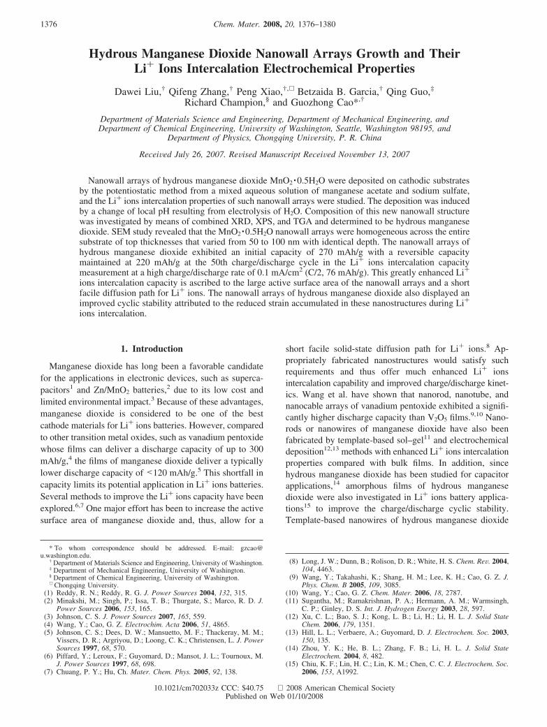
In order to understand the electrochemical reactions duringthe deposition process, cyclic voltammetry curve wasmeasured with Pt-coated Si substrates as both cathode andanode, and platinum film was also used as the referenceelectrode. The electrolyte was 0.1 M sodium sulfate aqueoussolution with a pH of 6.5. The voltage scan range was from-2 to 2 V versus platinum with a scan rate of 0.1 V/s. Figure3a revealed that water electrolysis occurred when the cathodicpotential was below -0.8 V versus platinum, resulting inthe formation of both hydrogen gas and hydroxyl ions, asindicated as region I. Such a reaction resulted in an increasein pH in the vicinity of the cathode. Water electrolysisoccurred at the anode as well when the electrode potential
rose higher than ∼1.4 V versus platinum to form oxygengas and protons as well as a reduction of pH value at thevicinity of anode. However, the overall pH of the electrolytesolution would remain unchanged. A duplicated CV testusing the same cathode and anode but Ag/AgCl as referenceelectrode showed that the hydrogen gas formed around -0.6V and the oxygen gas formed around 1.6 V, proving thecathodic property of the deposition.
Initially, the Mn2+ cations within the electrolyte solutionwere attracted to the negative polarity of the cathode surface,and then the local pH would change in the vicinity of cathodeas a result of the electrolysis of water, which resulted in theprecipitation of manganese hydroxide as schematically indicatedin Figure 3b. As reported previously,22 when the local pHreached 8 and above, the following reaction would happen.
Mn2+ + 2OH- ) Mn(OH)2 (1)
This deposition mechanism is similar to the growth ofvanadium oxide nanorod arrays from VO2
+ solution reportedin the literature.23,24 The combination of simultaneous releaseof hydrogen gas bubbles from the cathode surface andprecipitation of Mn(OH)2 in the vicinity prevented a com-pacted organization of the deposit on the cathode surface.Instead, nanostructured porous films or nanowall arrays ofmanganese hydroxide were formed. As to the initial deposi-tion sites of the interface between the Pt film andMnO2 ·0.5H2O nanowall arrays, considering that the deposi-tion was achieved through a precipitation induced by thechange of local pH value as a result of water electrolysis onthe surface of cathode, it was unlikely that a dense orcontinuous film would form at the bottom. A dense filmwould block the direct charge transfer between the cathodeand water molecules. The release of H2 gas bubbles as abyproduct of water electrolysis from the interface betweenthe cathode and electrolyte would also hinder the formationof a continuous dense film at the bottom.
Manganese hydroxide is not a stable compound in thepresence of oxygen; thus, Mn(OH)2 is readily oxidized to amixture of Mn3O4 and MnO2, the ratio of which depends onthe oxidation conditions such as different oxygen absorptionlevels and pH values according to the literature.22 In ourexperiment, only MnO2 was detected by the XPS data,indicating the oxidation to MnO2 during deposition andsubsequent drying processes through the following reaction:22
2Mn(OH)2 + O2 ) 2MnO2 + 2H2O (2)
No literature has so far been reported about the fabricationof manganese dioxide nanowall structure through thiscathodic electrochemical route, and the method reported hereis very promising for the fabrication of nanostructureelectrodes considering its easy control of operation andchemical purity.
The resultant nanowall arrays of hydrous manganesedioxide deposited at -1.8 V were subjected to a systematicelectrochemical analysis. The sample mass was estimated
(20) Nagarajan, N.; Humadi, H.; Zhitomirsky, I. Electrochim. Acta 2006,51, 3039.
(21) Ho, W. H.; Yen, S. K. J. Electrochem. Soc. 2005, 152, 506.
(22) Nichols, A. R.; Walton, J. H. J. Am. Chem. Soc. 1942, 64, 1866.(23) Cao, G. Z. J. Phys. Chem. B 2004, 108, 19921.(24) Takahashi, K.; Limmer, S. J.; Wang, Y.; Cao, G. Z. Jpn. J. Appl.
Phys. 2005, 44, 662.
Figure 3. (a) Cyclic voltammetry curve of a 0.1 M sodium sulfate aqueoussolution with a pH of 6.5, showing the reactions of water electrolysis. RegionI: 2H2O + 2e- ) H2 + 2OH-; region II: no electrolysis of H2O; regionIII: 2H2O ) O2 + 4H+ + 4e-. (b) Schematics showing the proposed growthmechanism of manganese hydroxide nanowall structure on cathodes dueto the increased pH value resulting from water electrolysis.
1379Chem. Mater., Vol. 20, No. 4, 2008Hydrous Manganese Dioxide Nanowall Arrays

to be 0.45 mg by using an electronic microbalance to getthe weight difference between pristine substrate and that withdeposited sample after drying. Figure 4a displays andcompares the first two discharge and charge curves ofnanowall arrays. The nanowall electrode showed excellentdischarge properties with a discharge capacity of 270 mAh/gin its first charge/discharge cycle at a rate of 0.1 mA/cm2
(C/2, 76 mAh/g), i.e., corresponding to a lithium intercalationratio of about 0.85 Li+ per MnO2, the same as reportedsol–gel prepared manganese dioxide.17 Additionally, thereversible capacity was also as high as 260 mAh/g in thesecond cycle, thus exhibiting good reversibility. The dis-charge capacity of the hydrous nanowall manganese dioxidewas higher than other reported hydrous manganese dioxidemeasured at an even lower current density of 61.4 mAh/g.25
Beyond the absolute value of the discharge capacities atvarious charge/discharge cycles, the high reversibility (nearly100% Coulombic efficiency) of the nanowall arrays electrodealso promised it a favorable battery cathode material.
Figure 4b summarizes the discharge capacities of thenanowall arrays of hydrous manganese dioxide deposited at-1.8 V over the first 50 cycles. Demonstrated is an initialdischarge capacity of 270 mAh/g followed by a small gradualloss of capacity from the early cycles. However, even at the50th cycle, the capacity was maintained at 220 mAh/g,displaying fine stability during cycling. The SEM image inFigure 5 of the nanowall arrays after 50 charge/dischargecycles revealed a likely explanation for the loss in capacity.It is likely that the exposed surface at the electrolyte-oxideinterface may have gradually dissolved during cycling, in
the SEM image standing out as the disappearance ofnanowall structure tips. This may result from erosion of theactive manganese dioxide surface due to reactions withatmospheric water absorbed into the electrolyte.26 Thus,available active manganese dioxide compound was gettingless and less, creating the capacity degradation.
The enhanced discharge capacity in nanowall array electrodesis readily attributed to the increase in surface area for thefaradaic reaction and short facile diffusion paths for Li+ ions.Similar improvements in performance due to increase of surfacearea of active material were reported on nanostructured elec-trodes of vanadium oxides.27 The roughly amorphous structureof hydrous manganese dioxide offers additional advantages. Inwell crystallized electrode materials, Li+ ions intercalation isoften accompanied with lattice structure distortion,28 leadingto significant capacity fading with successive charge/dischargecycles, whereas an approximately amorphous structure is lesswell packed and thus possesses greater ability for structuralaccommodation as well as more open free space during Li+
ions intercalation and diffusion.
4. Conclusions
Nanowall arrays of MnO2 ·0.5H2O were readily grown bycathodic electrodeposition of manganese hydroxide as a resultof water electrolysis-induced increase in local pH at thecathode surface. The morphological features of the 3-di-mensional nanostructures were controlled by variation in theexternally applied electric potential. The nanowall arrays,experimentally characterized as MnO2 ·0.5H2O, demonstratedexcellent Li+ ions intercalation properties with a highcapacity of 270 mAh/g due to its increased surface area, shortfacile diffusion paths, and generally amorphous composition.
Acknowledgment. This work has been supported in part byNational Science Foundation (DMI-0455994) and Air ForceOffice of Scientific Research (AFOSR-MURI, FA9550-06-1-032). Dr. Ying Wang is acknowledged for her valuable adviceon the electrochemical measurements. Prof. David Castner andstaff in NESAC/BIO lab, University of Washington, are owedspecial thanks for their help in the XPS measurement andanalyses.
CM702033Z
(25) Xu, J. J.; Jain, G.; Yang, J. Electrochem. Solid-State Lett. 2002, 5,152.
(26) Pan, L. J.; Pu, L.; Shi, Y.; Song, S. Y.; Xu, Z.; Zhang, R.; Zheng,Y. D. AdV. Mater. 2007, 19, 461.
(27) Wang, Y.; Takahashi, K.; Lee, K. H.; Cao, G. Z. AdV. Funct. Mater.2006, 16, 1133.
(28) Morales, J.; Sánchez, L.; Tirado, J. L. J. Solid State Electrochem. 1998,2, 420.
Figure 4. (a) Chronopotentiometric curves showing the Li+ ions intercala-tion behaviors and capacities of hydrous manganese oxide nanowall arraysdeposited at -1.8 V in the first and second charge/discharge cycles. (b)Li+ ions discharge capacity as a function of charge/discharge cycles betweenthe potential of 0.1 and -1.4 V vs Ag/AgCl at a specific current density of0.1 mA/cm2.
Figure 5. SEM image of the -1.8 V deposited nanowall arrays after 50cycles of charge/discharge test.
1380 Chem. Mater., Vol. 20, No. 4, 2008 Liu et al.