Hydronic Boilers - csiworldwide.comcsiworldwide.com/s/Laars Mighty Max HH Manual 2060E.pdf ·...
32
Installation, Operation and Maintenance Instructions Document 2060E H2090800E Installation, Operation and Maintenance Instructions for Mighty Max TM Hydronic Boilers Model HH Sizes 320M - 400M U.S. Reg. 1,901,192 Canada Reg. 433,882 WARNING If the information in this manual is not followed exactly, a fire or explosion may result causing property damage, personal injury or loss of life. Do not store or use gasoline or other flammable vapors and liquids in the vicinity of this or any other appliance. WHAT TO DO IF YOU SMELL GAS • Do not try to light any appliance. • Do not touch any electrical switch; do not use any phone in your building. • Immediately call your gas supplier from a nearby phone. Follow the gas supplier's instructions. • If you cannot reach your gas supplier, call the fire department. Installation and service must be performed by a qualified installer, service agency, or gas supplier. FOR YOUR SAFETY: This product must be installed and serviced by a professional service technician, qualified in hot water boiler installation and maintenance. Improper installation and/or operation could create carbon monoxide gas in flue gases which could cause serious injury, property damage, or death. Improper installation and/or operation will void the warranty. AVERTISSEMENT Assurez-vous de bien suivres les instructions données dans cette notice pour réduire au minimum le risque d’incendie ou d’explosion ou pour éviter tout dommage matériel, toute blessure ou la mort. Ne pas entreposer ni utiliser d’essence ni d’autres vapeurs ou liquides inflammables dans le voisinage de cet appareil ou de tout autre appareil. QUE FAIRE SI VOUS SENTEZ UNE ODEUR DE GAZ: • Ne pas tenter d’allumer d’appareils. • Ne touchez à aucun interrupteur. Ne pas vous servir des téléphones dansle bâtiment où vous vous trouvez. • Appelez immédiatement votre fournisseur de gaz depuis un voisin. Suivez les instructions du fournisseur. • Si vous ne pouvez rejoindre le fournisseur de gaz, appelez le sservice des incendies. L’installation et l’entretien doivent être assurés par un installateur ou un service d’entretien qualifié ou par le fournisseur de gaz.
Transcript of Hydronic Boilers - csiworldwide.comcsiworldwide.com/s/Laars Mighty Max HH Manual 2060E.pdf ·...

Installation, Operation and Maintenance Instructions Document 2060E
H20
9080
0E
Installation,Operation andMaintenanceInstructions for
Mighty MaxTM
Hydronic BoilersModel HHSizes 320M - 400MU.S. Reg. 1,901,192Canada Reg. 433,882
WARNINGIf the information in this manual is notfollowed exactly, a fire or explosion mayresult causing property damage, personalinjury or loss of life.
Do not store or use gasoline or otherflammable vapors and liquids in the vicinityof this or any other appliance.
WHAT TO DO IF YOU SMELL GAS• Do not try to light any appliance.• Do not touch any electrical switch; do not
use any phone in your building.• Immediately call your gas supplier from a
nearby phone. Follow the gas supplier'sinstructions.
• If you cannot reach your gas supplier, callthe fire department.
Installation and service must be performed bya qualified installer, service agency, or gassupplier.
FOR YOUR SAFETY: This product must be installed and serviced by a professional service technician,qualified in hot water boiler installation and maintenance. Improper installation and/or operation couldcreate carbon monoxide gas in flue gases which could cause serious injury, property damage, or death.Improper installation and/or operation will void the warranty.
AVERTISSEMENTAssurez-vous de bien suivres les instructionsdonnées dans cette notice pour réduire auminimum le risque d’incendie ou d’explosion oupour éviter tout dommage matériel, touteblessure ou la mort.
Ne pas entreposer ni utiliser d’essence nid’autres vapeurs ou liquides inflammables dansle voisinage de cet appareil ou de tout autreappareil.QUE FAIRE SI VOUS SENTEZ UNE ODEUR DE GAZ:
• Ne pas tenter d’allumer d’appareils.• Ne touchez à aucun interrupteur. Ne pas vous
servir des téléphones dansle bâtiment où vousvous trouvez.
• Appelez immédiatement votre fournisseur degaz depuis un voisin. Suivez les instructionsdu fournisseur.
• Si vous ne pouvez rejoindre le fournisseur degaz, appelez le sservice des incendies.
L’installation et l’entretien doivent être assurés parun installateur ou un service d’entretien qualifié oupar le fournisseur de gaz.

Page 2 LAARS HEATING SYSTEMS
SECTION 1.General Information1.1 Introduction .................................................... 31.2 Warranty ........................................................ 31.3 Technical Assistance ..................................... 3
SECTION 2.Installation Instructions2.1 General Information ....................................... 42.2 Boiler Placement ........................................... 42.3 Installation of Outdoor Boilers ....................... 42.4 Freeze Protection .......................................... 42.5 Installation of Indoor Boilers .......................... 52.5.1 Combustion Air Supply and Ventilation ......... 52.5.2 Removal of Existing Boiler ............................. 52.7 Water System Requirements ........................ 72.7.1 Flow Requirements ....................................... 72.7.2 Variable Water Flow Systems ....................... 82.7.3 System Pressure Requirements .................... 82.7.4 Hot/Chilled Water Systems............................ 82.7.5 Combined Space Heating/Potable
Water Heating Systems ................................. 92.8 Piping of System to Boiler ............................. 92.9 Filling the System ........................................ 102.10 Venting and Combustion Air Information ..... 122.11 Top-to-Rear Vent Collar Conversion ........... 122.12 Venting ........................................................ 132.12.1 Vertical Venting - Category I ........................ 132.12.2 Vertical Venting - Non Category I ................ 132.12.3 Horizontal Venting - Non Category 1 ........... 132.12.4 Side Wall Vent Terminal .............................. 142.13 Air for Combustion and Ventilation .............. 152.13.1 Air From Room ............................................ 152.13.2 Ducted Combustion Air ............................... 152.13.3 Conversion for Ducted
Combustion Air ............................................ 162.13.4 Combustion Air Piping ................................. 162.14 Electrical Wiring ........................................... 16
SECTION 3.Operating Instructions3.1 Start Up Requirements ................................ 183.2 Hi-Limit checkout ......................................... 193.3 Venturi and Gas Pressure
Regulator System ........................................ 193.3.1 Overall Operation ........................................ 193.4 To Start Up System ..................................... 193.4.1 Setting Temperature Controls ..................... 203.5 To Shut Down System ................................. 203.6 Venturi Adjustment - Natural Gas ................ 203.6.1 Pressure Measurement Ports -
Natural Gas ................................................. 203.6.2 Adjustment Procedure - Natural Gas........... 203.6.3 Venturi Setup Procedure ............................. 213.7 Venturi Adjustment - Propane Gas .............. 22
SECTION 4.Maintenance4.1 General Instructions .................................... 234.2 Heat Exchanger ........................................... 244.2.1 Inspection of the Heat Exchanger ............... 244.2.1a External Heat Exchanger Inspection ........... 244.2.1b Internal Heat Exchanger Inspection ............ 244.2.2 Cleaning the Heat Exchanger ..................... 244.2.2a Cleaning the Heat Exchanger - External ..... 244.2.2b Cleaning the Heat Exchanger - Internal ...... 254.3 Gas and Electric Controls ............................ 254.4 Filter ............................................................ 254.4.1 Filter Function .............................................. 254.4.2 Filter Service ............................................... 25
SECTION 5.Troubleshooting5.1 Sequence of Operation ............................... 255.2 Venturi and Gas Pressure
Regulator System ........................................ 265.2.1 Field Checkout ............................................ 265.3 Electrical Components ................................ 265.3.1 General Troubleshooting ............................. 265.3.2 Electrical Troubleshooting ........................... 26
SECTION 6.Parts List for Mighty Max HH Boiler6.1 General Information ..................................... 28
TABLE OF CONTENTS
Mighty Max Hydronic Boiler Page 3
(this information can be found on the rating plate),installation date, and name of the installer. Shippingcosts are not included in the warranty coverage.
Some accessory items are shipped in separatepackages. Inspect everything for damage immediatelyupon delivery, and advise the transporter of anyshortages or damage. Any such claims should be filedwith the transporter. The transporter will not accept aclaim from the shipper, Laars.
The warranty does not cover damage caused byimproper installation, operation, or field modification.
1.3 Technical AssistanceConsult the local factory representative or Laars
factory with any questions regarding the specification,installation, and operation of Laars equipment. Anexperienced technical support staff is ready to assist inassuring the proper performance and application ofLaars products.
Boiler Input Output
Size BTU/h kW BTU/h kW
320M 320,000 94 272,000 80
400M 399,000 17 339,150 99
Table 1. Input/Output Ratings.
SECTION 1.General Information
1.1 IntroductionThis manual contains installation, operation and
maintenance instruction for the Mighty Max hydronicboiler, Model HH, sizes 320M and 400M. Review allapplication and installation procedures completelybefore proceeding with the installation. Consult thelocal factory representative or Laars factory with anyquestions regarding this equipment. Experience hasshown that most operating problems are caused byimproper installation. The HH boilers are offered in anindoor version and an outdoor version (see Figure 1).Table 1 lists the input/output ratings for each boilersize.
The indoor version is convertible for outdoor usewith the installation of a conversion kit. See Section 6,Parts List, for part number.
1.2 WarrantyThe Mighty Max HH boilers are sold with a
limited factory warranty. Details are specified on theback cover of this manual.
Make all warranty claims to an authorized Laarsrepresentative or directly to the factory. Claims mustinclude the heater serial number and model number
Figure 1. Mighty Max HH Boiler Configuration.
INDOOR OUTDOOR
Front Side(Water Connections)
Rear Side(Opposite Water
Connections)

Page 4 LAARS HEATING SYSTEMS
SECTION 2.Installation Instructions
2.1 General InformationInstall the Mighty Max HH boiler in accordance
with the procedures in this manual (or the Laarswarranty may be voided), local codes, and ordinances.In the absence of such codes, install the heaters inaccordance with the latest edition of the National FuelGas Code, ANSI Z223.1/National Fire ProtectionAssociation (NFPA) 54. In Canada, the installationmust be in accordance with CSA B149.1 and localcodes. The authority having jurisdiction may requirethe installation be in accordance with the AmericanSociety of Mechanical Engineers (ASME) SafetyCodes for Controls and Safety Devices forAutomatically Fired Heaters, CSD-1. In Canada, otherstandards may apply. Any changes to the boiler, itsgas controls, gas orifices or wiring may void thewarranty. If field conditions require change, consultthe factory.
The Mighty Max HH boiler is designed-certifiedfor installation on a combustible floor. Do not installthe boiler directly on carpeting.
2.2 Boiler Placement
Clearance From Indoor OutdoorCombustibles Inches mm Inches mm
Top 18 457 UnobstructedWater Conn. Side 12 305 12 305Opposite Side 6 152 6 152Front Alcove UnobstructedRear 6 152 6 152Vent *6* 152 —Flooring Combustible Combustible
Service clearance = 24 in. (610mm) at front of boiler.*1 in. (25mm) if double wall vent is used.
Table 2. Minimum Boiler Clearancesfrom Combustible Surfaces.
Locate the boiler to provide adequate clearanceson all sides for maintenance and inspection. Theremust also be minimum distances maintained fromcombustible surfaces (See Table 2).
The boiler must be isolated or otherwiseprotected from any source of corrosive chemicalfumes, such as trichlorethylene, perchlorethylene,chlorine, etc. Install the boiler so that the gas ignitionsystem components are protected from water(drippings, spraying, rain, etc.) during operation andservice.
2.3 Installation of Outdoor Boilers
CAUTIONOutdoor installations are not recommended in areaswhere the danger of snow blockage exists.
ATTENTIONLes installations extérieures ne sont pasrecommandées dans les endroits ou il peut y avoirobstruction par la neige.
1. Locate the boiler to provide at least the minimumclearances as listed in Section 2.2, “BoilerPlacement.” HH boilers require an outdoorterminal kit when installed outdoors (see Section6, Parts List).
2. Do not locate the boiler in an enclosure orthrough-wall recess. Avoid locations where winddeflection off structures might cause down-draft.When such wind conditions are possible, locatethe boiler at least 3 feet (.9m) from structures.
3. Never install the boiler under any kind of roofoverhang. Do not locate the boiler below oradjacent to any doors, windows, louvers, grills,etc. which communicate in any way with aninhabited area of a building, even though suchcommunication might be through anotherstructure such as a garage or utility room (seeFigure 2).
2.4 Freeze ProtectionBoiler installations are not recommended in areas
where the danger of freezing exists unless properprecautions are made for freeze protection.Maintaining a mixture of 50% water and 50%properly inhibited HVAC glycol is the preferredmethod of freeze protection for hydronic systems. (Donot use automotive antifreeze.) This mixture willprotect the boiler to temperatures of about -35°F(-37°C). To get the desired temperature rise across the
WRONGWINDOWOR GRILL
INDOORROOM
Figure 2. Incorrect Installation of Boiler.

Mighty Max Hydronic Boiler Page 5
boiler when this mixture is used, increase the waterflow recommendation by 15%. Increase the head lossrequirement by 20%. Note: If your application doesnot require the full freeze protection of a 50%/50%mixture, it is beneficial to use a maximum 30% glycolsolution. This mixture will protect the boiler totemperatures of about 5°F (-15°C), and will serve asburst protection for boilers that are not in use.
Power outage, interruption of gas supply, failureof system components, activation of safety devices,etc., may prevent a boiler from firing. Any time aboiler is subjected to freezing conditions, and theboiler is not able to fire, and/or the water is notable to circulate, there is a risk of freezing in theboiler or in the pipes in the system. When waterfreezes, it expands. This can result in bursting of pipesin the system, or damage to the boiler, which couldresult in leaking or flooding conditions.NOTE: Different glycol products may provide varyingdegrees of protection. Glycol products must bemaintained properly in a heating system, or they maybecome ineffective. Consult the glycol specifications,or the glycol manufacturer, for information aboutspecific products, maintenance of solutions, and setup according to your particular conditions.
2.5 Installation of Indoor Boilers2.5.1 Combustion Air Supply and
VentilationThere are a variety of options available to the
installer when it comes to venting and combustion air;venting can be vertical or horizontal, it can originate atthe top of the boiler or the back, and combustion aircan be obtained from the room where the boiler isinstalled or ducted directly to the boiler from outdoors.See Sections 2.10 through 2.13 for details.
Mighty Max units are Category I fan-assistedwhen vented vertically and adhering to all applicablecodes. Mighty Max units are not allowed to be ventedinto a common horizontal vent system, unless aproperly-sized vent fan is used, and the common ventsystem is properly designed by the vent fanmanufacturer or a qualified engineer.
When common venting Mighty Max fan-assistedheaters with other appliances through one sharedvertical duct called a “common vent”, special caremust be taken by the installer to ensure safe operation.In the event that the common vent is blocked, it ispossible, especially for fan-assisted devices, to ventbackwards through non-operating appliances sharingthe vent, allowing combustion products to infiltrateoccupied spaces. If the appliances are allowed tooperate in this condition, serious injury or death mayoccur.
WARNINGOperation of appliances with a blocked commonvent may lead to serious injury or death. Safetydevices must be implemented to prevent blockedcommon vent operation. If safe operation of allappliances connected to a common vent cannot beassured, including prevention of spillage of fluegasses into living spaces, common venting shouldnot be applied, and appliances should each bevented separately.
It is for this reason that, in addition to followingproper vent sizing, construction and safetyrequirements from the National Fuel Gas Code, ANSIZ223.1 or in Canada, from CSA B149.1 as well as allapplicable local codes, it is required that installersprovide some means to prevent operation with ablocked common vent. It is suggested that a blockedvent safety system be employed such that if the switchfrom one appliance trips due to excessive stack spill orbackpressure indicating a blocked vent condition, thatall appliances attached to the vent be locked out andprevented from operating. (Note that the Mighty Maxunit is equipped with a blocked vent safety (pressure)switch, as shipped. As an additional precaution, it isrecommended that a Carbon Monoxide (CO) alarm beinstalled in all enclosed spaces containing combustionappliances. If assistance is required in determininghow a blocked vent safety system should be connectedto a LAARS product, please call ApplicationsEngineering at (603) 335-6300.
Refer to the installation and operatinginstructions on all appliances to be common vented forinstructions, warnings, restrictions and safetyrequirements. If safe operation of all appliancesconnected to a common vent cannot be assured,including prevention of spillage of flue gasses intoliving spaces, common venting should not be applied,and appliances should each be vented separately.
2.5.2 Removal of Existing BoilerAt the time of removal of an existing boiler, the
following steps shall be followed with each applianceremaining connected to the common venting systemplaced in operation, while the other appliancesremaining connected to the common venting systemare not in operation.1. Seal any unused openings in the common
venting system.2. Visually inspect the venting system for proper
size and horizontal pitch and determine there isno blockage or restriction, leakage, corrosion andother deficiencies which could cause an unsafecondition.

Page 6 LAARS HEATING SYSTEMS
corrosion et autres défaillances qui pourraientprésenter des risques.
3. Dans la mesure du possible, fermer toutes lesportes et les fenêtres du bâtiment et toutes lesportes entre l’espace, où les appareils tojoursraccordés et les autres espaces du bâtiment.Mettre en marche les sécheuses, tous lesappareils non raccordés au système d’évacuationcommun et tous les ventilateurs d’extractioncomme les hottes de cuisinère et les ventilateursdes salles de bain. S’assurer que ces ventilateursfonctionnent à la vitesse maximale, Ne pas fairefonctionner les ventilateurs d’été. Fermer lesregistres des cheminées.
4. Mettre l’appareil inspecté en marche. Suivre lesinstructions d’allumage. Régler le thermostat defaçon continue.
5. Faire fonctionner le brûleur principal pendant 5min ensuite déterminer si le coupe-tirage débordeà l’ouverture de décharge. Utiliser la flammed’une allumette ou d’une chandelle ou la afuméed’une cigarette, d’une cigare ou d’une pipe.
6. Une fois qu’il a été déterminé, selon la méthodeindiquée ci-dessus, que chaque appareil raccordéau systéme d’évacuation est mis à l’air libre defaçon adéquate. Remettre les portes et lesfenêres, les ventilateurs, les registres decheminées et les appareils au gaz à leur positionoriginale.
7. Tout mauvais fonctionnement du systémed’évacuation commun devrait êvacuationcommun devrait être corrigé de façon quel’installation soit conforme au National Fuel GasCode, ANSI Z223.1/NFPA 54 et (ou) aux codesd’installation CSA B149.1. Si la grosseur d’unesection du systéme devrait être modifié ppourrespecter les valeurs minimales des tableauxpertinents de l’appendice F du National Fuel GasCode, ANSI Z223.1/NFPA 54 et (ou) des codesd’installation CSA B149.1.
2.6 Gas Supply and PipingReview the following instructions before
continuing the installation.1. Gas piping installation must be in accordance
with the latest edition of ANSI Z223.1/NFPA 54.In Canada, the installation must be in accordancewith CSA B149.1 and all local codes that apply.See Figure 3 for boiler gas valve arrangement.
2. Check the rating plate to make sure the boiler isfitted for the type of gas being used. Laarsboilers are normally equipped to operate below a2000 foot (610m) altitude. Boilers equipped tooperate at high altitudes have appropriatestickers or tags attached.
3. Insofar as is practical, close all building doorsand windows, and all doors between the space inwhich the appliances remaining connected to thecommon venting system are located and otherspaces of the building. Turn on clothes dryersand any appliance not connected to the commonventing system. Turn on any exhaust fans, suchas range hoods and bathroom exhausts so theywill operate at maximum speed. Do not operate asummer exhaust fan. Close fireplace dampers.
4. Place in operation the appliance being inspected.Follow the lighting instructions. Adjustthermostat so appliance will operatecontinuously.
5. Test for spillage at the draft hood relief openingif the appliance is equipped with a drafthood,after 5 minutes of main burner operation. Use theflame of a match or candle, or smoke from acigarette, cigar or pipe.
6. After it has been determined that each applianceremaining connected to the common ventingsystem properly vents when tested as outlinedabove, return door, windows, exhaust fans,fireplace dampers and any other gas-burningappliances to their previous condition of use.
7. Any improper operation of the common ventingsystem should be corrected so the installationconforms with the National Fuel Gas Code,ANSI Z223.1. When resizing any portion of thecommon venting system, the common ventingsystem should be resized to approach theminimum size as determined using theappropriate Tables in Appendix G in theNational Fuel Gas Code, ANSI Z223.1.
In Canada, at the time the boiler is removedfrom common venting system, the common ventingsystem should be resized so the installation conformsto CSA B149.1.
2.5.2 Retrait de la Chaudière ExistanteAu moment du retrait d’une chaudière existante,
les mesures suivantes doivent être prises pour chaqueappareil toujours raccordé au système d’evacuationcommun et qui fonctionne alors que d’autres appareilstoujours raccordés au système d’évacuation nefonctionnent pas:1. Sceller toutes les ouvertures non utilisées du
système d’évacuation.2. Inspecter de façon visuelle le système
d’évacuation pour déterminer la grosseur etl’inclinaison horiztonale qui conviennent ets’assurer que le système est exemptd’obstruction, d’étranglement, de fuite, de

Mighty Max Hydronic Boiler Page 7
Notes: 1. These numbers are based on 1/2 inch (13mm) water column pressure drop.
2. Check supply pressure and local code requirements before proceeding with work.
3. Pipe fittings must be considered when determining gas pipe sizing.
Table 3. Natural Gas and Propane, Pipe Size Requirements.
Distance from Gas Meter or Last Stage Regulator
0-100 feet 100-200 feet 200-300 feet
0-30m 30-60m 60-90m
Natural Propane Natural Propane Natural Propane
Size in. mm in. mm in. mm in. mm in. mm in. mm
320M 1.25 32 1.25 32 1.50 38 1.25 32 1.50 38 1.50 38
400M 1.25 32 1.25 32 1.50 38 1.25 32 2.00 51 1.50 38
3. The figures in Table 3 should be used to size thegas piping from the gas meter to the boiler.Check local codes for BTU/h capacity required.
4. Install a sediment trap (drip leg) ahead of the gascontrols (see Figure 4). Fit the trap with athreaded cap which can be removed for cleaning.
5. When required by code, install a second manualgas shutoff valve. Do not remove manual shutoffvalve supplied with the boiler.
6. Disconnect the boiler and its individual shutoffvalve from the gas supply piping system duringpressure testing of the system at pressures higherthan 1/2 psi (3.5 kPa). Isolate the boiler from thegas supply piping system by closing itsindividual manual gas shutoff valve during anypressure testing of the gas supply piping systemat test pressures equal to or less than 1/2 psi(3.5 kPa).
7. Gas supply pressures to the boiler are listed inTable 4.
Supply PressureWater Column
Natural Gas Propane Gas
in. mm in. mm
Minimum 5 127 9 229
Maximum 9 229 14 356
Table 4. Gas Supply Pressure Requirements.
NOTE: The boiler and all other gas appliancessharing the boiler gas supply line must be firing atmaximum capacity to properly measure the inletsupply pressure. Low gas pressure could be anindication of an undersize gas meter and/orobstructed gas supply line.
8. Do not exceed the maximum inlet gas pressuresspecified. Excessive pressure will result indamage to the heater's gas controls. Theminimum pressures specified are for gas inputadjustment.
9. The correct differential gas pressure is stampedon the rating plate. The regulator is preset at thefactory, but may need adjustment for altitude perSection 3.
10. Before operating the heater, test the complete gassupply system and all connections for leaks usinga soap solution.
CAUTIONSince some leak test solutions (including soap andwater) may cause corrosion or stress cracking,rinse the piping with water after testing.
ATTENTIONComme certaines solutions qui testent les fuites (ycompris le savon et l’eau) peuvent causer de lacorrosion ou des fissures sous stress, rincez lestuyaux avec de l’eau après les tests.
2.7 Water System Requirements2.7.1 Flow RequirementsThe Model HH boilers must have continuous
flow through the heat exchanger when firing forproper operation. The system pump must be capableof developing sufficient pressure to overcome theresistance of the boiler plus the entire circulatingsystem at the designated flow (see Table 5). Thetemperature rise across the boiler should never exceed20°F (11°C). Minimum inlet water temperature is120°F (49°C).

Page 8 LAARS HEATING SYSTEMS
2.7.2 Variable Water Flow SystemsThere can be reduced water flow through the
boiler in heating systems using zone valves, zonepumps or 3-way valves. This can result in a hightemperature rise across the boiler. Laars recommendsprimary-secondary pumping for all variable flowsystems. The boiler pump in a primary-secondarysystem maintains constant flow through the boilereven though the system flow is variable. In a primary-secondary system the pressure drop of the boiler is notadded to the system (see Figure 5).
2.7.3 System Pressure RequirementsThe Model HH boilers are designed to operate
on closed, pressurized systems. Maintain a minimumof 12 psi (81.8 kPa) on the system where boiler supplywater temperature is 200°F (93°C) or less. If highertemperatures are required, the minimum systempressure should be at least 15 psi (102.2 kPa) above
Figure 4. T-Fitting Sediment Trap Installation.
Gas SupplyInlet
TeeFitting
3 In.(76mm) Min.
Cap
Nipple
To EquipmentInlet
Figure 3. Boiler Gas Valve Arrangement.
Note: The above diagram is a representation. Actualventuri assembly may vary depending on boiler size.
Venturi
Air ShutterEnclosure
Automatic,RegulatorandRedundantGas Valve
MixturePlenum
FilterHousing Blower
Motor
the water vapor pressure corresponding to the elevatedwater temperature.
The Model HH boilers are not suitable for opensystems unless the supply water temperatures arekept below 180°F (82°C), and a minimum of 5 psi(34.1 kPa) static head is maintained at the boiler.
2.7.4 Hot/Chilled Water SystemsWhen a boiler is connected to an air conditioning
system where the same water is used for heating andcooling, you must prevent chilled water from enteringthe boiler. When changing such a system from coolingto heating, allow the chilled water to circulate throughthe building, after the chiller has been turned off, for aperiod long enough for the water to warm up to atleast 105°F (41°C) before the water flows into theboiler. It is equally important to prevent hot waterfrom entering the chiller. The system shown in Figure6 is suggested to make sure the system water is neithertoo hot nor too cold when a changeover takes place.When a boiler is connected to heating coils located inair handling units (where they may be exposed torefrigerated air circulation), install a flow controlvalve or other automatic means to prevent gravitycirculation of chilled water through the boiler. Chilledwater in the boiler will create condensate on the boiler
NOTES: Sizes 320M and 400M use 4-pass heat exchangers.*Pressure drop (head loss) through the boiler, expressed in ft. of H2O.Shaded area is the recommended flow and temperature rise. Minimum inlet temperature is 120°F (49°C).
Table 5. Temperature Rise.
TEMPERATURE RISE IN DEGREES (°F / °C )
MODEL10°F 6°C 15°F 8°C 20°F 11°C
GPM H/L ft. LPS H/L m GPM H/L ft. LPS H/L m GPM H/L ft. LPS H/L m
HH0320M 54 11.2 3.41 3.4 36 5.0 2.27 1.5 27 2.8 1.70 0.9
HH0400M 68 26.2 4.29 8.0 45 11.5 2.84 3.5 34 6.6 2.15 2.0
Flow High Normal Low

Mighty Max Hydronic Boiler Page 9
tubes. Boilers installed in violation of the foregoingmay void the warranty.
2.7.5 Combined Space Heating/PotableWater Heating Systems
When using the Mighty Max boiler as a sourceof heat for a combined space heating/potable waterheating system, be sure to follow the instructions ofthe space heating system.
Do not use water piping, fittings, valves, pumps,and any other components which are not compatiblewith potable water.
Do not connect the heater, which will be used tosupply potable water, to any heating system orcomponents previously used with a nonpotable waterheating system.
Do not add boiler treatment or any chemicals tothe heating system piping, since the piping containswater for potable use.
Do not use solder containing lead in the potablewater lines.
Some jurisdictions may require a backflowpreventer in the cold water line. In such cases,pressure relief valve may discharge water due toexpansion. An expansion tank approved for potablewater will eliminate this condition. Follow themanufacturer's instructions for installation of theexpansion tank.
2.8 Piping of System to Boiler1. Be sure to provide gate valves at the inlet and
outlet to the boiler so it can be readily isolatedfor service.
2. The pressure relief valve installed in the tappedopening provided in the outlet header must bepiped, but not fastened, to a drain or floor sink.The drain pipe must be the same size as the valveoutlet and must pitch downward from the valve. Ifthe PRV supplied with the boiler is not factoryinstalled, install it in the front header consistentwith the ANSI/ASME Boiler and Pressure VesselCode, Section IV. Pay special attention to reliefvalve settings in installations where the boiler islocated on the ground floor of a tall building, orwhere the operating temperature of the boiler isabove 210°F (99°C). In both instances, the staticpressure of the system is elevated and could causethe relief valve to leak and bring considerable rawwater into the system. Where no special setting ofthe relief valve is ordered, the factory will furnisha 75 psi (511.5 kPa) setting. Never reduce therelief valve opening. If necessary, install the reliefvalve in a Tee immediately past the boiler outlet.
3. Provide a boiler installed above radiation levelwith a low water cutoff device either as part ofthe boiler or at the time of boiler installation (seeFigure 7).
4. Install manual and/or automatic bleeding devicesat high points in the system to eliminate air.
Figure 5. Primary-Secondary Plumbing.
Boiler CirculationPump
Cold WaterMake-Up
System Pump
12"Max.
12"Max.
12"Max.12"
Max.
Thermometer
TemperatureSensor
Globe Valve
Check Valve
Pressure Reducing Valvew/Fast Fill Bypass
Expansion Tankwith Air Scoop andAuto Air Vent
3-Way Valve
Valve
Pump
LEGEND:
Boiler circuit piping must be equal to or largerthan boiler water connection size.
Boiler circulation pump sized for flow throughboiler.
Dotted devices indicate alternate locations.
WARNING: This drawing shows suggestedpiping configuraiton and valving. Check withlocal codes and ordinances for additionalrequirements.
PurgeValve

Page 10 LAARS HEATING SYSTEMS
Install a correctly sized expansion orcompression tank with suitable air charger andtank drainer, as appropriate.
5. Support the weight of all water and gas piping bysuitable hangers or floor stands.
6. Check piping diagrams with local applicableplumbing, heating and building safety codes.
2.9 Filling The System1. Ensure the system is fully connected. Close all
bleeding devices and open make-up water valve.Allow system to fill slowly.
2. If make-up water pump is employed, adjustpressure switch on pumping system to provide aminimum of 12 psi (81.8 kPa) at the highestpoint in the heating loop.
3. If a water pressure regulator is provided on themake-up water line, adjust the pressure regulatorto provide at least 12 psi (81.8 kPa) at thehighest point in the heating loop.
4. Open bleeding devices on all radiation units atthe high points in the piping throughout thesystem, unless automatic air bleeders areprovided at such points.
5. Run system circulating pump for a minimum of30 minutes with the boiler shut off.
6. Open all strainers in the circulating system,check flow switch operation, and check fordebris.
3-Way Valve No. 1Change-Over(Heating and Cooling)
3-Way Valve No. 2To By-PassBoth Heater andChiller
ToSystem
FromSystem
By-Pass
To BoilerandChiller
FromBoiler
Valve Motors2-Pos3-Wire - 24V
115/24VTransformer
DPDT Manual or AutomaticChange-Over SwitchDPDT - Set at Change-OverTemperature
Clock TimerAuto-ResettingSet at 15 Minute SPDT
Suggested Wiring Diagram ForTempering System Water at
Changeover From Heating To Cooling
Figure 6. Boiler-Chiller Installation.
FromChiller
7. Recheck all air bleeders as described in Step 4above.
8. Check liquid level in expansion tank. With thesystem full of water and under normal operatingpressure, the level of water in the expansion tankshould not exceed 1/4 of the total, with thebalance filled with air.
9. Start up boiler according to procedure describedin Section 3.1. Operate the entire system,including the pump, boiler, and radiation unitsfor one (1) hour.
10. Recheck the water level in the expansion tank. Ifthe water level exceeds 1/4 of the volume of theexpansion tank, open the tank drainer and drainto that level.
11. Shut down the entire system and vent allradiation units and high points in the systempiping as described in Step 4 above.
12. Close make-up water valve and check strainer inpressure reducing valve for sediment or debrisfrom the make-up water line. Reopen make-upwater valve.
13. Check gauge for correct water pressure and alsocheck water level in the system. If the heightindicated above the boiler insures that water is atthe highest point in the circulating loop, then thesystem is ready for operation.
Make-UpWaterSupply
CheckValve
PressureReducingValve
Blow DownValve
ExpansionTank
To Drain
Method 1
ToDrain
Method 2
ToSystem
Strainer PumpThermometer
Temperatureand PressureGauge
NOTES: Select Method 1 or 2 when using low water cutoff accessory:1. Under Method 1, the low water cutoff is furnished by Laars and
shipped as a separate item for fieldinstallation.2. Under Method 2, electronic low water cutoff isinstalled, wired and
tested on boiler in Laars factory.3. Preferred locaiton of system pump is shown. Compression tank must
always be on suction side of pump.
Figure 7. Boiler Piping.
Air Changerand TankDrainer

Mighty Max Hydronic Boiler Page 11
Category I
Vertical Ventingwith Ducted
Combustion Air
Horizontal VentingAny Vent Which Does Not Meet
Category I Combustion AirThrough Louvers
Horizontal VentingDucted Combustion Air
(Certified As Direct Vent)
Non-Category I
Exhaust Terminal Detail
Side ViewWall
Figure 8. Venting and Combustion Air Options.
Vertical Venting (Category I)Combustion Air InThrough Louvers
Side ViewWallNOTE:All views are shown
from rear of heater
HorizontalIntake Terminal Detail
(Combustion Air)
Screen ProvidedOn Vertical Intake
Air Terminal
For vertically ducted combustion air:• Combustion air intake must
terminate at least 3 feet (0.91m)lower than vent termination, if it islocated within a 10 foot (3.05m)radius.
• Combustion air intake must be atleast 1 foot (0.3m) above roof topand normal snow levels.

Page 12 LAARS HEATING SYSTEMS
the latest edition of ANSI Z223.1/NFPA 54. InCanada, installation must be in accordance with CSAB149.1, and applicable local codes.
There are a variety of ways to provide ventingand combustion air for the boiler (see Figure 8).
The Mighty Max HH boiler is certified as a truedirect vent unit when installed according to theinstructions for horizontal venting and ductedcombustion air. This can be done even if the runs arevertical.
2.11Top-to-Rear Vent Collar ConversionThe Mighty Max HH boiler is shipped with the
vent collar on top of the heater. Follow this procedureto convert it for rear connection (see Figure 9).
Figure 9. Top-To-Rear Vent Collar.
Adapter Plate
Top Panel
VentCollar/Stack
Blank Plate(BoilerJacket)
Blank Plate OnFlue Collector
Blank Plate OnBoiler Jacket
Top Panel
1. Removal of Blank Plate and AdapterPlate From Boiler
3. Blank Plate PlacementOver Stack Top Opening
Blank Plate(Flue
Collector)
VentCollar/Stack
2. Removal of Blank Plate FromRear of Flue Collector
4. Connecting Vent Collar/Stackto Flue Collector
14. Within three (3) days of start-up, recheck all airbleeders and the expansion tank as described inSteps 4 and 8 above.
IMPORTANTThe installer is responsible for identifying to theowner/operator the location of all emergencyshutoff devices.
2.10Venting and Combustion AirInformationProvisions for venting and supply of air for
venting and combustion must be done in accordancewith these instructions and applicable requirements of

Mighty Max Hydronic Boiler Page 13
IMPORTANT: Maximum pipe length allowed is 50 feet (15m), regardless of the number of elbows. Maximum number of elbows allowed is 5.Vent pipe minimum clearance from combustible surfaces is 6 inches (152mm).
Table 7. Vent Piping Specifications (Combustion Air Exhaust).
1. Remove the adapter plate from the top panel.2. On the boiler jacket, remove the top panel and
ease its lip from under the edge of the bonnet togain access to the flue collector.
3. Remove the vent collar/stack from the fluecollector. Do not damage the vent collar/stackduring removal.
4. Remove the blank plate from the rear of thejacket.
5. Remove the blank plate from the rear section ofthe flue collector. Be careful not to lose theinsulation attached to the plate.
6. Apply high temperature sealant and install theblank plate (previously removed from the rearsection of the flue collector) on top of the fluecollector.
7. Install the blank plate (previously removed fromthe rear of the boiler jacket) over the stackopening on the top panel of the boiler.
8. Apply high temperature sealant (see Table 6) tovent collar/stack and install on the rear of theflue collector.
Term Description
Pipe Must comply with UL Standard 1738such as type 29-4C stainless steel
Joint Sealing Follow vent manufacturer'sinstructions
Insulation Recommended, but not required,minimum R5 with protective cover
Table 6. Required Horizontal Venting Material.
9. Slip the adapter plate over the vent collar/stackand install it onto the rear boiler jacket (seeFigure 9).
2.12VentingVenting must be in accordance with these
instructions and applicable requirements of the latestedition of ANSI Z223.1/NFPA 54. In Canada,installation must be in accordance with the latestedition of CSA B149.1, and applicable local codes.
2.12.1 Vertical Venting - Category IThe Mighty Max boiler has a fan-assisted
combustion system, so vertical vents must be installedin accordance with the special code requirements forCategory I - Fan-Assisted Appliances. Theserequirements can be found in the latest edition ofANSI Z223.1/NFPA 54, Appendix G, Table 1, and inCanada, CSA B149.1, Amendment No. 1. These codespermit installation as a single appliance or incombination with other Category I appliances.However, there are very important requirements forminimum and maximum vent diameter and length.Make sure vertically-vented installations comply withthese codes.
NOTE: If a vent cannot be installed in accordancewith the requirements of these codes, it must beinstalled as a horizontal vent, even if it is mainlyvertical.
2.12.2 Vertical Venting - Non-Category IWhen venting does not meet the code
requirements for Category I - Fan-Assisted VerticalVents, it can develop positive pressure. Such ventingmust be installed in accordance with this section orSection 2.12.3.
The following requirements must be used forNon-Category I venting:
1. Laars specified vent pipe material (Table 6) andsizes (Table 7).
2. Pipe insulation and sealing tape.3. Routing vent pipe through spaces which, except
for the terminal, remain above 60°F (16°C)during heater operation.
2.12.3 Horizontal Venting - Non-Category IWhen venting is horizontal, or cannot meet the
code requirements for Category I - Fan-AssistedVertical Vents, it can develop positive pressure andmust be installed in accordance with this section.
The following requirements must be used forHorizontal Venting - Non-Category I:
1. Laars specified vent pipe material (Table 6) andsizes (Table 7).
2. Laars side wall vent hood.3. Pipe insulation and sealing tape.
Heater Pipe Diameter Max Pipe Length Max No.Side Wall Side Wall
Size of ElbowsVent Terminal Combustion Air
in. mm in. mm Part Number Terminal Part Number
320M 6 152 50 15 5 D2004500 20260701400M 7 178 50 15 5 D2004600 20260702

Page 14 LAARS HEATING SYSTEMS
4. Routing vent pipe through spaces which, exceptfor the terminal, remain above 60°F (16°C)during heater operation.
2.12.4 Side Wall Vent TerminalThe side wall vent hood must be used when the
heater is vented through a side wall. It provides ameans of installing vent piping through the buildingwall, and must be located in accordance with ANSIZ223.1/NFPA 54 and applicable local codes. InCanada the installation must be in accordance withCSA B149.1 and local applicable codes (see Figure10). Consider the following when installing theterminal:1. Locate the vent terminal so that it will not be
damaged by pedestrians and other traffic, and sothe discharge is not objectionable. The NationalFuel Gas Code requires a through-wall ventterminal be at least 7 feet (2.1m) above grade iflocated at a public walkway.
2. Locate the vent terminal so that vent gasescannot be drawn into air conditioning systeminlets. The National Fuel Gas Code requires thatit be at least 6 feet (1.8m) above any such inletthat is within 10 feet (3.0m).
3. Locate the vent terminal so that vent gasescannot enter the building through doors,windows, gravity inlets or other openings. TheNational Fuel Gas Code requires that it belocated at least 4 feet (1.2m) below, 4 feet (1.2m)horizontally from, or 3 feet (0.9m) above suchopenings.
4. Locate the vent terminal so that it cannot beblocked by snow. The National Fuel Gas coderequires that it be at least 12 inches (305mm)above grade, but the installer may determine itshould be higher depending on local conditions.
5. Locate the terminal so the vent exhaust does notsettle on building surfaces and other nearbyobjects. Vent products may damage suchsurfaces or objects. But the actual construction ofthe vent terminal and the flow of vent productsmust not be altered.
6. Locate the terminal at least 6 feet (1.8m)horizontally from any gas or electric metering,regulating, or relief equipment, or buildingopening.
Figure 10. Building Exterior.
Dimensions shown in feet (m).
Vent Hood
7 (2.1) MinimumAbove Public
Walkway
Vent Hood
Vent Hood
1 (0.3) Above Grade
4 (1.2)Minimum
Vent Hood Must BeMounted 4 (1.2)
Minimum Below Windows
3 (0.9m) Minimum
Vent Hood
4 (1.2)Minimum
6 (1.8) Above AnyOutside Air Intake
Within 10 (3.0)
VentHood

Mighty Max Hydronic Boiler Page 15
2.13Air for Combustion and VentilationThe boiler requires air for combustion and the
space around the boiler requires ventilation.Combustion air can be provided by standard practicesas specified in the installation codes (ANSI Z223.1/NFPA 54, in Canada, CSA B149.1 and localapplicable codes), or ducted directly to the boiler.Ventilation air must be provided in either case.
2.13.1 Air From RoomStandard requirements for providing air for
combustion and ventilation are provided by ANSIZ223.1/NFPA 54 and in Canada by CSA B149.1.These codes require passages be provided for air flowinto the space where the boiler is installed. The size ofthese passages is based on the firing rate of the boilerand the path of air flow into the space. In general,installations which take air from inside the buildingrequire larger passages than those which take airdirectly through an outside wall.
Failure to provide adequate combustion andventilation air can cause the boiler, and otherappliances occupying the same space, to operate withdangerous and inefficient combustion, and can causeoverheating of the space. Be sure to provide airpassages in accordance with ANSI Z223.1/NFPA 54,in Canada, CSA B149.1 and local applicable codes,and do not permit any other condition, such as anexhaust blower, to affect the air supply for combustionand ventilation.
2.13.2 Ducted Combustion AirCombustion air can be brought directly to the
boiler through a duct of suitable size and length (seeTable 7). Consult Laars about installations not coveredby Table 7.
Combustion air must be taken from out-of-doorsby means of the Laars side wall terminal.Locate the terminal within 10 feet (3.0m) of the boilervent exhaust terminal, but no closer than 3 feet (0.9m)(centerline distance).
Do not locate the air inlet terminal near a sourceof corrosive chemical fumes (e.g., cleaning fluid,chlorine compounds, etc.). Locate it so that it will notbe subject to damage by accident or vandalism. It mustbe at least 7 feet (2.1m) above a public walkway.
Use single-wall galvanized pipe for thecombustion air duct. Route the duct to the heater asdirectly as possible. Seal all joints with tape. Provideadequate hangers. The heater must not support theweight of the combustion air duct.
When combustion air is ducted to the boiler,other provisions must be made for boiler roomventilation. HH boilers lose less than 1 percent of theirinput rating to the room, but other heat sources may bepresent. Provide enough ventilation air to meetcomfort specifications. Make sure the ventilation air is
Figure 11. Ducted Combustion Air Conversion.
Ducted CombustionAir Pipe
InletPipe
AdapterPlate
LouveredPlate
Boiler Size Assembly Number
320 20258101
400 20258102
Table 8. Combustion Air Assembly.
not directed at the boiler, water piping or otherequipment which could be damaged by freezing.

Page 16 LAARS HEATING SYSTEMS
2.14Electrical Wiring
WARNINGElectrically ground the heater in accordance withthe latest edition of ANSI/NFPA 70. In Canada, useCSA C22.1. Do not rely on the gas or water pipingto ground the metal parts of the heater. Often,plastic pipe or dielectric unions isolate the boilerelectrically. Service and maintenance personnelwho work on or around the boiler may be standingon wet floors and could be electrocuted by anungrounded boiler. Electrocution can causseserious injury or death.
AVERTISSEMENTLa chaudière doit être mise à la terre selon lesexigences officielles locales ou, en l’absence detoute instruction officielle, l’installation doit êtreconforme avec la dernière édition du Codeélectrique canadien CSA C22.1, Partie 1, auCanada. N’utilisez pas la tuyauterie de gaz oud’eau pour mettre à la terre les parties métalliquesde la chaudière. Les unions diélectriques ou avectuyau en plastique peuvent isoler la chaudièreélectriquement. Les membres du personnel deservice et d’entretien qui travaillent sur et autour dela chaudiére peuvent marcher sur des planchersmouillés et pourraient se faire électrocuter par unechaudière non mise à la terre.
1. Check boiler wiring and pump for correctvoltage, frequency, and phase.
2. Wire the boiler and pump exactly as shown inthe wiring diagram supplied with the boiler (seeFigure 12).
3. Electrically interlock the pump and boiler so theboiler cannot come on unless the pump isrunning.
4. Connect all field-installed devices (relays,timers, temperature devices, etc.) to the boilerwiring at points labeled “Field Interlock” (seeFigure 12).
2.13.3 Conversion for DuctedCombustion Air
The conversion to ducted combustion airrequires the parts listed in Table 8. Follow theseprocedures to convert the heater (see Figure 11):1. Remove the louvered plate from the left side of
the boiler.2. Remove the adapter plate from the shipping
container.3. Install the blower motor housing collar in gasket.4. Slip one end of the inlet pipe over the collar on
the adapter plate.5. Slide the inlet pipe and adapter plate into the
boiler opening until the pipe is aligned with theblower motor.
6. Slip the end of the inlet pipe over the blowermotor housing collar.
7. Secure the adapter plate to the side of the boilerwith the 4 screws.
2.13.4 Combustion Air PipingRun piping of the appropriate size between the
air intake terminal and the boiler (see Table 7). Table9 lists the materials for piping the boiler.
Term Description
Pipe Single-wall galvanized steel pipe,24 gauge minimum.
Joint Sealing Permanent duct tape or aluminumtape
Insulation Not required, but recommend R5insulation for cold installations(consult American Society ofHeating, Refrigerating, andAir Condditioning Engineers(ASHRAE) handbook
Table 9. Required Combustion Air Piping Material.

Mighty Max Hydronic Boiler Page 17
Figure 12. Wiring Diagram.
CO
NN
EC
TIO
ND
IAG
RA
M
LIG
HT
BK
CO
M
NO
24
V
CO
M
BL
R
FU
SIB
LE
LIN
K
FA
N
115V
24V
11
5V
/60
Hz
PO
WE
RS
UP
PLY
W
FU
SE
2A
MP
IND
S1
L1
FS
/S2
MV
1P.S
WT
H
Y
FIE
LD
INT
ER
LO
CK
P
PR
E.P
LO
BL
R
(RE
MO
VE
JU
MP
ER
WH
EN
US
ED
)
GR
OU
ND
ING
JU
NC
TIO
N
GA
SV
ALV
E
IGN
ITE
R
TR
AN
SF
OR
ME
R
IGN
ITIO
N
TE
MP
ER
AT
UR
ES
EN
SO
R
SE
NS
OR
24V
AC
BL
W W
BK
BK
L2
GN
D
4
3
2
16
TIM
E
O
HO
T
NE
UT
RA
L
CO
ND
UC
TO
RG
RO
UN
DIN
G
BK
BK
BL
BK
RB
R
WB
KB
K
BR
W
G
BR
WW
BK
BKWBK
BR
BK
BK
W
RR
R
R
R
Y
SW
ITC
H
R
Y
BR
Y
Y
Y
BL
TR
TH
CO
LO
RL
EG
EN
D
FA
CT
OR
YW
IRIN
G
24
V
11
5V
FIE
LD
WIR
ING
24
V
11
5V
NO
TE
S:
2.T
HE
DE
NO
TE
SO
PT
ION
AL
CO
MP
ON
EN
TS
.*
3.
RE
MO
VE
JU
MP
ER
WH
EN
US
ING
FIE
LD
INT
ER
LO
CK
.
4.
EL
EC
TR
ICA
LW
IRIN
GM
US
TB
EIN
AC
CO
RD
AN
CE
WIT
HA
NS
I/N
FP
A7
0A
ND
TH
EL
AT
ES
TE
DIT
ION
OF
CA
NA
DIA
NE
LE
CT
RIC
AL
CO
DE
.
5.
IFA
NY
OF
TH
EO
RIG
INA
LW
IRE
AS
SU
PP
LIE
DW
ITH
TH
EA
PP
LIA
NC
EM
US
TB
ER
EP
LA
CE
D,
ITM
US
TB
ER
EP
LA
CE
DW
ITH
1.A
LL
WIR
ING
TO
BE
10
5°C
,6
00
VW
IRE
RA
TIN
G.
AP
PL
IAN
CE
MA
TE
RIA
L(1
05
°C)
OF
EQ
UIV
AL
EN
TG
AU
GE
S(A
WG
).
C
NCNO
FU
SIB
LE
LIN
K
MA
NU
AL
RE
SE
TH
IGH
LIM
IT
HIG
HL
IMIT
AU
TO
RE
SE
T
CO
NT
RO
LL
ER
TE
MP
ER
AT
UR
E
CO
NT
RO
L
DE
LA
Y
LO
WW
AT
ER
CU
TO
FF
PO
WE
RO
N
TO
GG
LE
CO
MB
US
TIO
N
BK
SW
ITC
HT
EM
PB
UR
NE
R
STA
CK
PR
ES
SU
RE
SW
ITC
H
CN
O
NC
SC
HE
MA
TIC
WIR
ING
DIA
GR
AM
BR
VE
NT
UR
ID
IFF
ER
EN
TIA
LP
RE
SS
UR
ES
WIT
CH
STA
CK
PR
ES
SU
RE
SW
ITC
H
BU
RN
ER
TE
MP
ER
AT
UR
ES
WIT
CH
6.
PU
MP
ISF
IEL
D-S
UP
PL
IED
.
SW
ITC
HF
LO
W
BR
SW
ITC
HF
LO
W
BR
TH
TR
*
P 1 2 3 4 5
51 2 43P
DIF
FE
RE
NT
IAL
VE
NT
UR
I
PR
ES
SU
RE
SW
ITC
H
IGN
ITE
R
CO
MB
US
TIO
NFA
N
M
GA
SV
ALV
E
LIN
KF
US
IBLE
CO
NT
RO
LT
EM
PE
RA
TU
RE
24V
AC
CO
M
L1
MV
1IN
DPR
E.P S1
FS
/S2
LO
CO
M
NO
24V
FU
SIB
LE
LIN
K
FU
SE
LW
CO
6
24V
115V
RE
LA
YP
UM
P
2 34 1
LIG
HT
PO
WE
RO
N
CO
NT
RO
LIG
NIT
ION
TH
GN
DL2
MA
NU
AL
RE
SE
TH
IGH
LIM
IT
RE
SE
T
LIM
IT*
HIG
H
AU
TO
.
XF
MR
M
PU
MP
3P
OS
.S
WIT
CH
HO
TN
EU
TR
AL
PU
MP
6M
BK
-B
LA
CK
W-
WH
ITE
R-
RE
DY
-Y
EL
LO
WB
L-
BL
UE
BR
-B
RO
WN
O-
OR
AN
GE
G-
GR
EE
NP
-P
UR
PL
EB
R/Y
-B
RO
WN
WIT
HY
EL
LO
WB
L/Y
-B
LU
EW
ITH
YE
LL
OW
3
6
3
Page 18 LAARS HEATING SYSTEMS
SECTION 3.Operation
WARNINGDo not use this appliance if any part has beenunder water. Immediately call a qualified servicetechnician to replace the appliance.
AVERTISSEMENTN’utilisez pas cet appareil s’il a été en partiesubmergé. Appelez immédiatement un technicienqualifié pour remplacer l’appareil.
3.1 Start Up RequirementsLighting: Safe lighting and other performance
criteria were met with the gas manifold and controlassembly provided on the boiler when it underwenttests specified in ANSI Z21.13 Standard.
Before placing the boiler in operation, check theautomatic safety shutoff devices. Once the boiler isconnected to the gas piping and after all of therequirements in Section 2 have been met, follow thisprocedure:
1. Before beginning the tests, make sure the mainmanual gas valve, and any other boiler firingvalves, are in the OFF position.
NOTE: The gas valve is turned off as follows:
2. Press in gas control knob slightly and turnclockwise to OFF. Knob cannot be turned unlessit is pushed in slightly. Do not force it.
3. Make sure the power switch on the boiler is inthe ON position. Reset all safety devices (highlimit, pressure switch, Low-Water-Cutoff, etc.).
4. Normal Operating SequenceWhen the circulation pump is running, the boilerwill turn itself on and off in response to the watertemperature. When the water cools below the settemperature, the following sequence occurs:
a. The aquastat powers the ignition control.
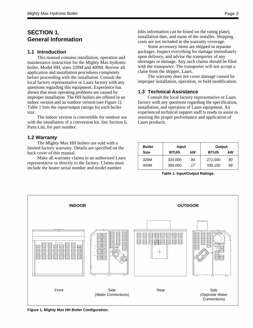
b. The ignition control turns on thecombustion fan. After about a 15 secondpre-ignition purge, while the fan clears thecombustion chamber, the igniter is turnedon. The igniter takes about 25 seconds toheat up. You can see a glow through theview port (see Figure 13).
NOTE: The manual gas valve must be ON for the burnerto ignite. This valve is turned ON as follows:
c. Turn counterclockwise to ON.
d. When the igniter is hot, the ignition controlturns on the gas valve and the burnerignites. You can see the burner flamethrough the view port (see Figure 13).
JunctionBox
Front View of Boiler
NOTE: Sight glasslocation may vary.
Figure 13. Periodic Flame Observation.
Igniter
Sight GlassFor Flame Observation
e. The boiler operates until the aquastat sensesthat the water is hot enough, and the burnershuts off. The combustion fan runs forabout one minute to blow all combustionproducts out of the boiler.
If the igniter fails to ignite the burner in step 3(for example, if there is air in the gas line), the ignitioncontrol shuts off the gas valve after a few seconds ofoperation. The purge and ignition sequence isautomatically repeated. If there is no ignition in threetries, the ignition control “locks out” until the problemis corrected. Contact a qualified service technician.
3.1 Critères de démarrageÉclairage: L’éclairage ainsi que d’autres critères
de sureté ont été verifiés avec les commandes de gazinstallées sur la chaudière au cours des test effectuésqui sont recommandés dans le ANSI Z21.13 Standard.
Avant de mettre la chaudière en marche, vérifiezle dispositif de sûreté d’arrêt automatique. Une foisque la chaudière est branchée à la tuyauterie de gaz etune fois que toutes les conditions de la Section 2 ontété remplies, suivez cette démarche :1. Avant de commencer les tests, assurez-vous que
la valve manuelle principale de gaz et toutes lesautres valves de démarrage de la chaudière sonten position OFF (arrêt).
NOTA: La valve de gaz est arrêtée comme suit :2. Appuyez légèrement sur le bouton de contrôle de
gaz et tournez-le dans le sens des aiguilles d’unemontre à OFF. Le bouton ne peut pas tourner àmoins d’appuyer légèrement. Ne pas forcer.
3. Assurez-vous que l’interrupteur sur la chaudièreest en position ON (marche). Réglez tous lesdispositifs de sécurité (limite haute, interrupteurde pression, arrêt-eau-minimum, etc.).
4. Séquence normale d’opération. Quand la pompe

Mighty Max Hydronic Boiler Page 19
de circulation est en marche, la chaudière semettra automatiquement en marche ou s’arrêteraen fonction de la température de l’eau. Quandl’eau refroidit au-dessous de la températureréglée, il se produira la séquence suivante :a. L’aquastat met en marche la commande
d’allumage.b. La commande d’allumage met en marche le
ventilateur de combustion. Après une purgede pré-allumage d’environ15 secondes,tandis que le ventilateur dégage la chambrede combustion, l’allumeur se met enmarche. L’allumeur met environ 25secondes pour chauffer. Vous pouvez voirune lueur par le hublot d’inspection (voirFigure 13).
NOTA: La valve manuelle de gaz doit être enposition ON pour que le brûleur s’allume. Cettevalve se met en marche comme suit :
c. Tournez sur ON dans le sens contraire desaiguilles d’une montre.
d. Quand l’allumeur est chaud, le contrôled’allumage tourne la valve de gaz et lebrûleur s’allume. Vous pouvez voir laflamme du brûleur par le hublotd’inspection (voir Figure 13).
e. La chaudière fonctionne jusqu’à ce quel’aquastat détermine que l’eau est assezchaude et le brûleur s’arrête. Le ventilateurde combustion continue pendant encoreenviron une minute pour évacuer tous lesproduits de combustion de la chaudière.
Si l’allumeur n’arrive pas à allumer le brûleurdans la troisième étape (par exemple, s’il y a de l’airdans le tuyau de gaz), la commande d’allumage fermela valve de gaz après quelques secondes defonctionnement. La séquence de purge et d’allumageest répétée automatiquement. S’il n’y a pas d’allumageaprès trois essais, la commande d’allumage « sebloque » jusqu’à ce que le problème soit corrigé.Appelez un technicien de service qualifié.
3.2 Hi-Limit CheckoutAfter running the boiler for a long enough period
to bring the water temperature within the range of thehi-limit, slowly back off the high limit setting until theboiler shuts off. The main burners should re-ignitewhen the hi-limit is turned back up to its originalsetting and the hi-limit is reset.
3.3 Venturi and Gas Pressure RegulatorSystem
3.3.1 Overall OperationThe gas control system of the Mighty Max boiler
is similar to that of a carburetor of a gasoline engine: aventuri pulls the gas into the combustion air stream(see Figure 14). In this system, changes in combustionair flow automatically change the gas flow.
The flow of air through the venturi creates apressure difference. At the narrowest point of theventuri, the throat, high velocity creates a low pressurecondition which pulls gas in through an orifice.
For a correct gas/air ratio, the gas pressure mustbe the same as the air pressure, but with a slightnegative offset. A special gas regulator (called a“negative pressure regulator”) which has an equalizertube connected to the venturi inlet, maintains therequired gas pressure.
When the system is operating, a combustion fanforces air into the venturi, creating pressure at theinlet. The gas regulator sets gas pressure, and gas ispulled through the orifice. The sizes of the venturithroat and gas orifice are factory set to provide thecorrect air/gas ratio.
3.4 To Start Up System(See Section 3.1 for Startup Requirements)
1. Be certain the system pump is running.2. Set the thermostat or aquastat to its lowest
setting.3. Turn off electric power to the appliance.4. Remove the control access panel.5. Turn off the manual gas valve.6. Wait five (5) minutes to clear out any gas, then
smell for gas, including near the floor. Be sure tosmell next to the floor because some gas isheavier than air and will settle on the floor.
CAUTIONThis appliance is equipped with an ignition devicewhich automatically lights the burner. Do not try tolight the burner by hand.
ATTENTIONCet appareil est équipé avec un dispositifd’allumage qui allume automatiquement le brûleur.N’essayez pas d’allumer le brûleur manuellement.
WHAT TO DO IF YOU SMELL GAS• Do not try to light any appliance.• Do not touch any electric switch; do not use any
phone in your building.

Page 20 LAARS HEATING SYSTEMS
• Immediately call your gas supplier from aneighbor's phone. Follow the gas supplier'sinstructions.
If you don't smell gas, go to the next step.7. Turn on manual gas valves.8. Rest all safety devices (manual resets on high
limit, low water cutoff, etc.).9. Replace control access panel.10. Turn on all electric power to the boiler.11. Set thermostat to desired setting.12. If the boiler will not operate, follow the
instructions to turn off gas to boiler and call yourservice technician or gas supplier.a. Turn off main electrical switch.b. Close all manual gas valves.
3.4.1 Setting Temperature ControlsThe temperature control differential is factory
set at 15°F. This setting can be adjusted from 1 to30°F to suit your application. Adjustment is made bytaking the cover off the temperature controller andturning the potentiometer marked “DIFF”, which islocated just below and to the left of the controller’ssetpoint dial.
To set the temperature and high-limit controls:a. Set the temperature controller at the system
design temperature.b. For boilers with the temperature controller bulb
at the boiler inlet, set the high-limit 40°F to 50°Fabove temperature controller setting.
c. For boilers with the temperature controller bulbat the boiler outlet, set the high-limit 15°F to25°F above temperature controller setting.
3.5 To Shut Down SystemTo shut down the boiler, turn off all manual gas
valves and electrical disconnect switch.
NOTE: There is a filter which needs to be cleanedprior to setting pressures. See Section 4.4.2 “FilterService” before proceeding.
3.6 Venturi Adjustment - Natural GasVerifying proper operation of the combustion
flow system has two aspects - air flow and gas flow.Air flow is checked by measuring pressures at servicetaps on the venturi. Gas flow is checked by evaluatingventuri pressures and the regulator offset pressure.
In a venturi flow system the difference betweenvarious pressures is far more important than their“gauge” value relative to the room. The gas pressureoffset and the gas orifice pressure differential areespecially important concepts. The following sectiondescribes this setup procedure.
3.6.1 Pressure Measurement Ports -Natural Gas
Air flow enters the venturi through the filter boxand blower assembly. It is pushed through aconverging section and into the throat, where pressureis reduced substantially. Gas flow is pulled into thethroat through an orifice. The orifice is locatedbetween the throat and the regulator. Air and gas arecombined in the throat and mix thoroughly as theyproceed through the venturi tailpipe to the burner.
Service taps are provided at three places. One islocated on the chamber with the gas connection, thistap is called the gas plenum tap. The other is locatedabove the gas plenum tap, this port is called theventuri inlet tap. The third tap, gas orifice tap, islocated on the red orifice holder directly before the gasconnects to the venturi. These taps have service plugsin them. Do not remove any of the plastic fittings orplastic tubing. To evaluate system operation requiresaccurate measurement at these taps. An inclinedmanometer with a zero to 6 inches water column rangeis ideal. Other instruments may be used, but the“positive/negative” nature of the readings must bewell understood. Gas pressure offset measurements areat very low levels (0.4" WC), the instrumentation mustbe capable of determining it accurately (see Figure 15,16 and 17).
3.6.2 Adjustment Procedure - Natural GasNote that an equalizer tube is connected from a
port on the side of the venturi inlet to the port of theregulator. This is a very important component whichallows the regulator to track air pressure even whenabnormal conditions occur, such as blockage of thecombustion air. Before firing, confirm that this tube
OverallOperation
Figure 14. Typical Venturi System.
Air EqualizerTube
NegativePressure Regulator
Gas
GasOrifice
Air/GasMixture

Mighty Max Hydronic Boiler Page 21
and the venturi pressure switch tubes are in place andfirmly connected.
The field checkout involves measuring gas andventuri pressures, and observing the flame through thesight glass. If necessary, the gas input rate can bemeasured by timing the gas meter.
Install shutoff valves at the gas orifice (regulatoroutlet) tap (red), at the venturi inlet tap and at the gasplenum tap. Do not remove any of the plastic fittingsor plastic tubing. After installing the shutoff valves, becertain they are closed.
a. Unfired Venturi Differential Pressure -Natural Gas
NOTE: Turn off the main manual gas valve.
The difference in pressure between the venturiinlet tap and the gas plenum tap (see Figure 15). Thismeasurement is taken by connecting the positive sideof the manometer to the venturi inlet tap andconnecting the negative side of the manometer to thegas plenum tap. This measurement is taken with theboiler not firing. It is a temporary setting used to startthe boiler and check for air flow problems.
b. Gas Offset Pressure - Natural GasThe difference in pressure between the venturi
inlet tap and the outlet of the gas regulator (seeFigure 16). This measurement is taken by connectingthe positive side of the manometer to the venturi inlettap and connecting the negative side of the manometerto the gas orifice tap. This measurement is anindication of the gas to air ratio and must beperformed while the unit is firing.
c. Gas Orifice Differential Pressure -Natural Gas
This measurement is the pressure drop across thegas orifice. This measurement is taken by connectingthe positive side of the manometer to the gas orificetap and the negative side of the manometer to the gasplenum tap (see Figure 17). This measurement inconjunction with the gas orifice size is an indication ofthe gas firing rate and must be performed while theunit is firing.
By setting the gas offset pressure and gas orificedifferential pressure according to Table 10, the correctinput rate and gas to air ratio is achieved.
GAS GAS ORIFICE UNFIREDELEVATION, OFFSET DIFFERENTIAL VENTURI
FT PRESSURE PRESSURE DIFFERENTIALinch W.C. inch W.C. inch W.C.
SEA LEVEL +0.4 +4.0 +5.82000 +0.4 +3.7 +5.34000 +0.4 +3.4 +4.96000 +0.4 +3.2 +4.68000 +0.4 +2.9 +4.2
10000 +0.4 +2.7 +3.9
Table 10. Venturi Pressure Settings - Natural Gas.
3.6.3 Venturi Setup Procedure -Natural Gas
1. Loosen the nut on the blower shutter to allow foradjustment. Turn the heater on so that the bloweris running and the heater is not firing. Measurethe unfired venturi differential pressure. In thisunfired condition, adjust the shutter until theunfired venturi differential pressure is accordingto Table 10, “Unfired Venturi Differential” (5.8± .3 inches wc at sea level). If this pressure rangecan not be achieved, check for blockage in thecombustion air inlet, boiler and venting system.If there is no obvious cause contact a qualifiedLaars service technician.
2. Approximately 40 seconds after the blower startsthe gas valves will open. The heater is nowfiring. If the heater is not running, check allmanual gas valves and heater safety devices.Ensure proper gas supply pressures according toTable 4 in Section 2.
3. Measure the gas offset pressure. Using theregulator only, adjust the gas offset pressureaccording to the installation’s altitude in Table 10(+0.4 inches wc. at sea level). REPLACE THEREGULATOR CAP BEFORE TAKING GASPRESSURE READINGS. Turn the regulatorscrew clockwise to decrease the gas offsetpressure, turn the regulator screwcounterclockwise to increase the offset.
4. Using the toggle switch, turn the heater off. Turnthe heater back on and check the gas offsetpressure while the heater is firing. If the gasoffset pressure is not according to Table 10,adjust the regulator as needed.
5. Measure the gas orifice differential pressure.This pressure must be adjusted according toTable 10 (4.0 ± .2 inches wc at sea level). Usethe blower shutter to adjust the gas orificedifferential.
6. By adjusting the gas orifice differential, the gasoffset pressure will change. Therefore you mustrepeat steps 3-5 until the gas offset and gasorifice differential pressures are according toTable 10.

Page 22 LAARS HEATING SYSTEMS
Figure 16. Gas Offset Pressure - Natural Gas.
Figure 17. Gas Orifice Differential Pressure - Natural Gas.
Figure 15. Unfired Venturi Differential Pressure - NaturalGas.
7. After setting all pressures, turn the heater off andreplace each shutoff valve with the factoryinstalled threaded plugs. The venturi has nowbeen adjusted for proper operation.
3.7 Venturi Adjustment - Propane GasThe field checkout involves measuring gas and
venturi pressures, and observing the flame through thesight glass. If necessary, the gas input rate can bemeasured by timing the gas meter.
Use a single, inclined manometer or digitalmanometer with a 4.0 inch water column range. Installshutoff valves at the gas orifice (regulator outlet) tap(red), at the venturi inlet tap (blue) and at the venturithroat tap (yellow). After installing the shutoff valves,be certain they are closed (see Figure 18).1. With the heater off, connect the positive side of
the manometer to the shutoff valve on the venturiinlet tap (blue). Open the shutoff valve.
2. Loosen the nut on the blower damper to allowfor adjustment. Turn the boiler on so that theblower is running and the boiler is not firing. Inthis unfired condition, adjust the damper until theventuri inlet pressure (blue tap) is 1.2 incheswater column.
3. Approximately 40 seconds after the blower startsthe gas valves will open. The boiler is nowfiring. If the heater is not running, check allmanual gas valves and heater safety devices.

Mighty Max Hydronic Boiler Page 23
screw clockwise to decrease the gas pressureoffset, turn the regulator screw counter-clockwise to increase the offset.
6. Using the toggle switch, turn the heater off. Turnthe heater back on and check the gas pressureoffset after the heater has fired. If the gas offsetpressure is not according to Table 11, adjust theregulator as needed.
7. While the heater is still running, close the shutoffvalve on the gas orifice tap (red), then removethe manometer hose from the shutoff valve.Connect the negative side of the manometer tothe shutoff valve on the venturi throat tap(yellow). This reading is called the venturi throatdifferential pressure and should appear accordingto altitude in Table 11 (+2.6" w.c. at sea level). Ifit does not appear according to Table 11, contacta qualified service technician.
After setting all pressures, turn the heater off andreplace each shutoff valve with the factory installedthreaded plugs. The venturi has now been adjusted forproper operation.
SECTION 4.Maintenance
4.1 General Instructions
1. Oil the water circulating pump in accordancewith the manufacturer's instructions.
2. Oil the blower motor bearings every 6 months.3. If a strainer is used in a pressure reducing valve
or in the piping, clean it every 6 months inaccordance with the manufacturer's instructions.
4. At startup and every 6 months after, look at themain burner flame for proper performance. Theburner should not require maintenance in normaloperation. If any malfunction indicates that theburner needs service (e.g., a flame that is yellow,or entire burner surface glowing red), call aprofessional service technician. Flamecharacteristics may be inspected during the first30 seconds after ignition. Characteristics of agood flame are:a. Blue flame color.b. Dark-colored burner surface with
occasional glowing fibers on surface.
NOTE: After 30 seconds of operation the combustionchamber will heat up and prevent reliable flameobservation.
5. Inspect the venting system for blockage, leakage,and corrosion at least once a year.
6. Keep the heater area clear of combustiblematerial, gasoline, and other flammable liquidsand vapors.
“Low” Side ofManometer
“High” Side ofManometer
Venturi InletTap (Blue)
Venturi ThroatTap (Yellow)
Gas OrificeTap (Red)
Figure 18. Measurement of Venturi Throat PressureDifferential - Propane Gas.
Ensure proper gas supply pressures according tothe table in Section 2.
4. Now that the boiler is firing, use the blowerdamper to readjust the venturi inlet pressureaccording to the installation’s altitude in Table11 (+1.6" w.c. at sea level).
Elevation Venturi Inlet Gas ThroatFt. Pressure Pressure Differential
(Blue Tap) Offset Pressure“WC H20” “WC H20” “WC H20”
SEA LEVEL +1.6 +0.4 +2.6
1000 +1.5 +0.4 +2.5
2000 +1.5 +0.4 +2.4
3000 +1.4 +0.4 +2.3
4000 +1.4 +0.3 +2.2
5000 +1.3 +0.3 +2.2
6000 +1.3 +0.3 +2.1
7000 +1.2 +0.3 +2.0
8000 +1.2 +0.3 +1.9
9000 +1.1 +0.3 +1.9
10000 +1.1 +0.3 +1.8
Table 11. Venturi Pressure Settings - Propane Gas.
5. Leaving the positive side of the manometerconnected to the venturi inlet tap (blue), connectthe negative side of the manometer to the shutoffvalve on the gas orifice tap (red). Open theshutoff valve to take a pressure reading. Thisreading is called the gas pressure offset. Usingthe regulator only, adjust the gas pressure offsetaccording to the installation's altitude in Table 11(+0.4" w.c. at sea level). REPLACE THEREGULATOR CAP BEFORE TAKING GASPRESSURE READINGS. Turn the regulator
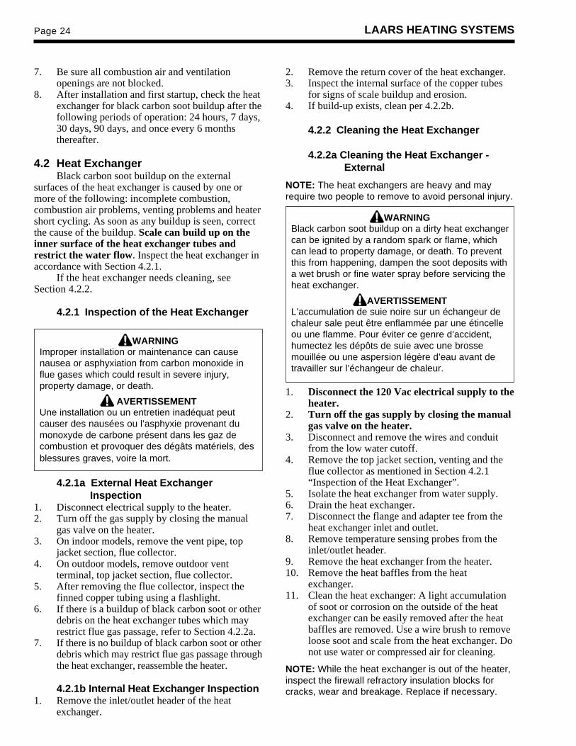
Page 24 LAARS HEATING SYSTEMS
7. Be sure all combustion air and ventilationopenings are not blocked.
8. After installation and first startup, check the heatexchanger for black carbon soot buildup after thefollowing periods of operation: 24 hours, 7 days,30 days, 90 days, and once every 6 monthsthereafter.
4.2 Heat ExchangerBlack carbon soot buildup on the external
surfaces of the heat exchanger is caused by one ormore of the following: incomplete combustion,combustion air problems, venting problems and heatershort cycling. As soon as any buildup is seen, correctthe cause of the buildup. Scale can build up on theinner surface of the heat exchanger tubes andrestrict the water flow. Inspect the heat exchanger inaccordance with Section 4.2.1.
If the heat exchanger needs cleaning, seeSection 4.2.2.
4.2.1 Inspection of the Heat Exchanger
WARNINGImproper installation or maintenance can causenausea or asphyxiation from carbon monoxide influe gases which could result in severe injury,property damage, or death.
AVERTISSEMENTUne installation ou un entretien inadéquat peutcauser des nausées ou l’asphyxie provenant dumonoxyde de carbone présent dans les gaz decombustion et provoquer des dégâts matériels, desblessures graves, voire la mort.
4.2.1a External Heat ExchangerInspection
1. Disconnect electrical supply to the heater.2. Turn off the gas supply by closing the manual
gas valve on the heater.3. On indoor models, remove the vent pipe, top
jacket section, flue collector.4. On outdoor models, remove outdoor vent
terminal, top jacket section, flue collector.5. After removing the flue collector, inspect the
finned copper tubing using a flashlight.6. If there is a buildup of black carbon soot or other
debris on the heat exchanger tubes which mayrestrict flue gas passage, refer to Section 4.2.2a.
7. If there is no buildup of black carbon soot or otherdebris which may restrict flue gas passage throughthe heat exchanger, reassemble the heater.
4.2.1b Internal Heat Exchanger Inspection1. Remove the inlet/outlet header of the heat
exchanger.
2. Remove the return cover of the heat exchanger.3. Inspect the internal surface of the copper tubes
for signs of scale buildup and erosion.4. If build-up exists, clean per 4.2.2b.
4.2.2 Cleaning the Heat Exchanger
4.2.2a Cleaning the Heat Exchanger -External
NOTE: The heat exchangers are heavy and mayrequire two people to remove to avoid personal injury.
WARNINGBlack carbon soot buildup on a dirty heat exchangercan be ignited by a random spark or flame, whichcan lead to property damage, or death. To preventthis from happening, dampen the soot deposits witha wet brush or fine water spray before servicing theheat exchanger.
AVERTISSEMENTL’accumulation de suie noire sur un échangeur dechaleur sale peut être enflammée par une étincelleou une flamme. Pour éviter ce genre d’accident,humectez les dépôts de suie avec une brossemouillée ou une aspersion légère d’eau avant detravailler sur l’échangeur de chaleur.
1. Disconnect the 120 Vac electrical supply to theheater.
2. Turn off the gas supply by closing the manualgas valve on the heater.
3. Disconnect and remove the wires and conduitfrom the low water cutoff.
4. Remove the top jacket section, venting and theflue collector as mentioned in Section 4.2.1“Inspection of the Heat Exchanger”.
5. Isolate the heat exchanger from water supply.6. Drain the heat exchanger.7. Disconnect the flange and adapter tee from the
heat exchanger inlet and outlet.8. Remove temperature sensing probes from the
inlet/outlet header.9. Remove the heat exchanger from the heater.10. Remove the heat baffles from the heat
exchanger.11. Clean the heat exchanger: A light accumulation
of soot or corrosion on the outside of the heatexchanger can be easily removed after the heatbaffles are removed. Use a wire brush to removeloose soot and scale from the heat exchanger. Donot use water or compressed air for cleaning.
NOTE: While the heat exchanger is out of the heater,inspect the firewall refractory insulation blocks forcracks, wear and breakage. Replace if necessary.

Mighty Max Hydronic Boiler Page 25
4. Inspect the filter for discoloration due tocontamination or any other forms of debris. Ifcontamination or debris exists, wash the filter ina soap/water solution then rinse with water only.It is important that the filter be dry beforeplacing it back in the filter housing.
CAUTIONThe filter has arrows which indicate the direction ofthe air flow. Failure to install the filter correctly maycause blower failure and dangerous operation.
ATTENTIONLe filtre a des flèches qui indiquent la direction del’air. Si le filtre n’est pas installé correctement, lesouffleur peut ne pas fonctionner, ce qui seraitdangereux.
The filter must be inspected for contaminationone week after start-up. Depending upon the severityof contamination, a suitable cleaning schedule may bedeveloped. The factory recommends cleaning the filterat least once every 30 days. In high contaminationareas, such as construction sites, factories, etc., thefilter may need to be cleaned daily. Failure to do socould result in lower heat output and potential unsafeoperation.
SECTION 5.Troubleshooting
5.1 Sequence of OperationTo troubleshoot the heater properly you must
first understand the sequence of operation of theheater:1. Upon a call for heat a 24 Vac signal is sent
through fusible links and high limit(s) to theignition control “TH” terminal.
4.2.2b. Cleaning the Heat Exchanger -Internal
1. Remove the inlet/outlet header of the heatexchanger.
2. Remove the return cover of the heat exchanger.3. Clean the internal surface. (Laars offers a tube
cleaning kit part no. R00100000.)4. Reassemble in the reverse order.
4.3 Gas and Electric ControlsThe gas and electric controls on the heaters are
designed for both dependable operation and long life.Safe operation of the heater depends on their properfunctioning. A professional service technician shouldcheck the following basic items every year, andreplace when necessary.
NOTE: the warranty does not cover damage causedby lack of required maintenance or improperoperating practices.
1. Water temperature controls.2. Ignition control system.3. Automatic electric gas valve(s).4. Flow sensing safety device (when used).5. Low water cutoffs, including flushing or float
types. (Every six months)
Other maintenance requirements include:
1. Periodic cleaning of filters, when supplied.2. Lubrication of moving parts (when applicable),
with the correct type and amount of lubricant.3. Periodic examination of the venting system.4. Periodic cleaning of vent terminal screens, where
applicable.5. Cleaning flue gas passageways.
4.4 Filter4.4.1 Filter FunctionA filter has been designed into the operation of
this Mighty Max boiler. Its function is to filter thecombustion air before it is delivered to the burnersystem. The filter is manufactured out of apolyurethane foam and may be cleaned with a mildsoap and water solution. Clean the filter only after thefilter has been removed from the filter housing (seeFigure 19).
4.4.2 Filter Service(The filter does not need cleaning if this is a first
time heater start-up).
1. Turn the heater off using the toggle switch.
2. Remove the door panel and bonnet from thejacket.
3. Remove the screws on the filter housing toexpose the filter as shown in Figure 19.
Figure 19. Filter Exposed for Cleaning.
FILTER
ARROW

Page 26 LAARS HEATING SYSTEMS
2. The “IND” terminal of the ignition control isenergized for a 15 second pre-ignition purgeperiod during which the combustion blowerpurges the combustion chamber.
3. After the purge period there is a 20 to 35 secondigniter heat up period. The glow of the ignitercan be seen through the boiler sight glass.
4. Then there is a seven second trial for ignition.During this time the gas valves are energized andthe main burner ignites. The gas valves willremain energized throughout the call for heat aslong as the ignition control igniter senses a stableflame.
5. After the call for heat is satisfied the ignitioncontrol closes the gas valves and operates theblower for a thirty (30) second post purge cycle.This clears the combustion chamber ofcombustion products.
The ignition is attempted three times. If ignitionis not successful, the control shuts down and “locksout”. It remains in the lockout condition until theboiler is turned off then back on or 120 Vac power tothe boiler is interrupted.
5.2 Venturi and Gas Pressure RegulatorSystem
5.2.1 Field CheckoutSee Section 3.2 “Venturi and Gas Pressure
Regulator System” for proper setup procedure.
5.3 Electrical ComponentsThis section describes guidelines for checking
the operation of electrical components installed on theboiler. Refer to the wiring diagram for correctconnection locations.
5.3.1 General TroubleshootingThis section describes guidelines for checking
the electrical components of the boiler. Experience hasshown that most complaints about boilers failing tofire have nothing to do with the boiler itself. Usually,one of the protective switches in the boiler system hasshut down operation.
Any of the following can prevent properoperation. Check these items first:
1. Be sure the boiler has been properly installed(see Section 2).
2. Make sure the pump is not airlocked, clogged orotherwise inoperative.
3. Make sure the gas valve is on and there issufficient gas pressure in the line. All externalgas valves must be open.
4. Verify that the electrical circuit serving the boileris ON.
5. Make sure the toggle switch on the right side ofthe boiler is ON.
6. Check the fuse inside the black, twist-lock fuseholder. If it is burned, replace it with a 2-ampfuse (part no. E0084400).
7. With the power off inspect all electricalconnections and wiring. Finding a looseconnection or charred wire can save a lot of timeand money.
8. Make sure the temperature controller is set highenough to call for heat.
9. Make sure none of the manual reset controls, i.e.,low water cutoff, high limit, etc., have tripped.Reset any tripped switches.If the pump is circulating water and the
foregoing items check out okay, the trouble may be inthe boiler control system.
CAUTIONDisconnect power to the boiler before removing orreplacing any component or wire connection. If thepower is not disconnected, “jumping” the gas valveor accidentally grounding the wire harness orcomponent terminals to the boiler frame or jacketcould cause the ignition control fuse to blow.
ATTENTIONDébranchez la chaudière avant d’enlever ou deremplacer tout élément ou branchement de fil. Si lachaudière est branchée, « connecter » la valve degaz ou mettre accidentellement à la terre lefaisceau de fils ou des terminaux au corps ou à lagaine de la chaudière peut faire sauter le plomb(ou disjoncteur) de la commande d’allumage.
5.3.2 Electrical TroubleshootingTroubleshooting procedures should only be
performed by professional service techniciansqualified in heater maintenance.
Some electrical components are wired in parallel,so it is necessary to troubleshoot in the order that theyappear on the wiring diagram or the troubleshootingflow chart (see Figure 20).
NOTE: When testing the safeties between “MV1” ofthe ignition control and the gas valve(s) there is only aseven (7) second trial for ignition period during whichthere is power to “MV1”.
The following steps should be used whentroubleshooting the boiler:1. Remove the lower front panel (see Figure 21).2. Turn the manual gas valve on the heater off.3. If the heater has locked out turn the toggle switch
off for 5 seconds then back on to reset the heater.

Mighty Max Hydronic Boiler Page 27
Figure 20. Troubleshooting Chart.

Page 28 LAARS HEATING SYSTEMS
4. Use the troubleshooting flow chart (see Figure20) to determine what components and wiringshould be tested first.
5. Test each component by checking for 24 Vac or120 Vac entering and exiting the device. If thereis voltage entering the safety device, but noneleaving then there is an open circuit and it mustbe determined why it is open. When testingcomponents between “MV1” of the ignitioncontrol and the gas valve install a meter and letthe heater cycle through one complete sequenceof operation. During the sequence of operationthese safeties will only be energized for theseven second trial for ignition.
6. Turn the manual gas valve on the boiler on andfire the boiler.
SECTION 6.Parts List for Mighty Max HH Boiler6.1 General Information
To order or purchase parts for the Laars MightyMax HH boiler, contact your nearest Laars contractoror distributor. If they cannot supply you with whatyou need, contact:
Laars Customer Service Department6000 Condor DriveMoorpark, California 93021Telephone (805) 529-2000Telephone (800) 900-9276
In Canada, contact:Laars Customer Service Department480 S. Service Road WestOakville, Ontario, Canada L6K 2H4Telephone (905) 844-8233.
Item Description Part Number
1. Base Assembly320M ........................................................... 20157801400M ........................................................... 20157802
2. Burner and Burner Plenum Weldment320M ........................................................... 20268401400M ........................................................... 20268402
3. Venturi Assembly320M ........................................................... 20158601400M ........................................................... 20158602
4. Combustion Chamber Weldment320M ........................................................... 20159101400M ........................................................... 20159102
5. Gas Train Assembly320M ........................................................... 20254901400M ........................................................... 20254902
Gas Valve320M, 400M ................................................ V2003900
Orifice Holder320M, 400M ................................................ P2017500
6. Motor, Blower320M thru 400M Nat. & Prop. Gas ............. A2088100
7. Electrical ControlsHigh limit Control ........................................... E0015900Toggle Switch ................................................. E0109200Indicator Light ................................................ E0071300Fusible Link ................................................... E0099403Transformer ................................................... E0086100Fuse Holder ................................................... E2000300Fuse, 2 Amp .................................................. E2043600Flow Switch .................................................... E0013000Burner Temperature Switch ........................... E2076100Low Water Cutoff ........................................... E2075100Pump Time Delay .......................................... E2077700
8. Sight Glass .................................................... F00448009. Igniter, Hot Surface ....................................... W003800110. Gasket, Igniter Hot Surface ........................... 2040980011. Control, Remote Ignition ................................ E210130012. Control, Temperature ..................................... E210140013. Display, Temperature ..................................... E210160015. Heat Exchanger Assy., 4 pass, Copper Tubes
320M ........................................................... 20259601400M ........................................................... 20259602
Heat Exchanger Assy., 4 pass, Cupronickel tubes320M ........................................................... 20104701400M ........................................................... 20104702
16. Cover, Machined In/Out ................................. 2015020017. Plate, Mach. Adapter
320M, 400M ................................................ 2015030218. Flange, Machined
320M, 400M ................................................ 2025540019. Cover, Machined Rear ................................... 2015010020. Pressure Switch, Differential 320-775 ........... E0115200
Pressure Switch, Differential 1000 ................. E016140021. Flue Collector Assembly (with gaskets)
320M ........................................................... 20155401400M ........................................................... 20155402Figure 21. Lower Front Panel Removal.

Mighty Max Hydronic Boiler Page 29
Front View
Right Side View
36
10
8
9
5 20 7
12 13
11
3
6
21
15
38
41
2

Page 30 LAARS HEATING SYSTEMS
Front ViewRear View
Right Side ViewLeft Side View
3132
17
30
2326 27 28 25
37
25 33
16
18
352919
3439

Mighty Max Hydronic Boiler Page 31
Item Description Part Number
22. Jacket Assembly (not shown)320M ........................................................... 20255201400M ........................................................... 20255202
23. Covering Plate (side) ..................................... 2025650024. Collar, Jacket 320-400 ................................... 2025830025. Bonnet
320M ........................................................... 20156801400M ........................................................... 20156802
26. Panel Top,320M ........................................................... 20157501400M ........................................................... 20157502
27. Panel, Top Side, Left ...................................... 2015280028. Panel, Side, Left ............................................ 20152700

H20
9080
0E
Waterpik Technologies6000 Condor Drive, Moorpark, CA 93021 • 805.529.2000 • FAX 805.529.593420 Industrial Way, Rochester, NH 03867 • 603.335.6300 • FAX 603.335.3355480 S. Service Road West, Oakville, Ontario, Canada L6K 2H4 • 905.844.8233 • FAX 905.844.2635www.laars.com Litho in U.S.A. © Laars Heating Systems 0405 Document 2060E