
Hybrid Electrical Energy Storage Systems - Massoud … · Hybrid Electrical Energy Storage Systems....
71
Naehyuck Chang and Massoud Pedram Seoul National University University of Southern California Hybrid Electrical Energy Storage Systems Hybrid Electrical Energy Storage Systems
Transcript of Hybrid Electrical Energy Storage Systems - Massoud … · Hybrid Electrical Energy Storage Systems....

Naehyuck Changand
Massoud Pedram
Seoul National UniversityUniversity of Southern California
Hybrid Electrical Energy Storage Systems
Hybrid Electrical Energy Storage Systems

2
Outline
Electrical energy storage systemsEnergy storage elementsCharge management circuitsHybrid Electrical Energy Storage (HEES) systemsHEES optimization examples
Amortized system cost optimizationMaximum power transfer trackingRate capacity effect mitigation
Conclusions

3
Electrical Energy Storage Systems
DefinitionAn electrical energy storage (EES) systems use various forms of energy such as chemical, kinetic, or potential energy to store energy that will later be converted to electricity
Electrical energy has higher grade of energy qualityConverting electrical energy to other types of energy is efficient and easy but the opposite is not trueElectrical energy has a greater capacity to feedback and control lower grades of energy quality
ExamplesSupercapacitor: electrical energyBattery: chemical energyFlywheel: kinetic energyCAES (compressed air energy storage): potential energy

4
Electrical Energy Storage Systems
EES system functionalitiesPower supplyEnergy managementPower quality controlPeak shaving
Ranges of EES systemsPower supplies for portable electronics (a few Wh or smaller)Uninterruptible power supplies (hundreds of Wh)Grid-scale EES (GWh or larger)

5
Electrical Energy Storage Systems
Conventional EES systems mostly employ a single type of EES elementFocus is on the EES element characteristicsTry to achieve higher performance by using a more efficient EES element
Conventional EES systems have a rather simple architectureCharge/discharge circuitSingle power pathStraightforward charge/discharge policy
EES element: a storage device such as a battery and a supercapacitorEES system: an integrated system including EES element, control electronics, and control policy

6
Conventional EES Systems
ArchitectureA single type of EES elementA single power path from input, to the storage, and to output
The input and output may be tied together in some configurationsThe power path may be bidirectional in some cases
7
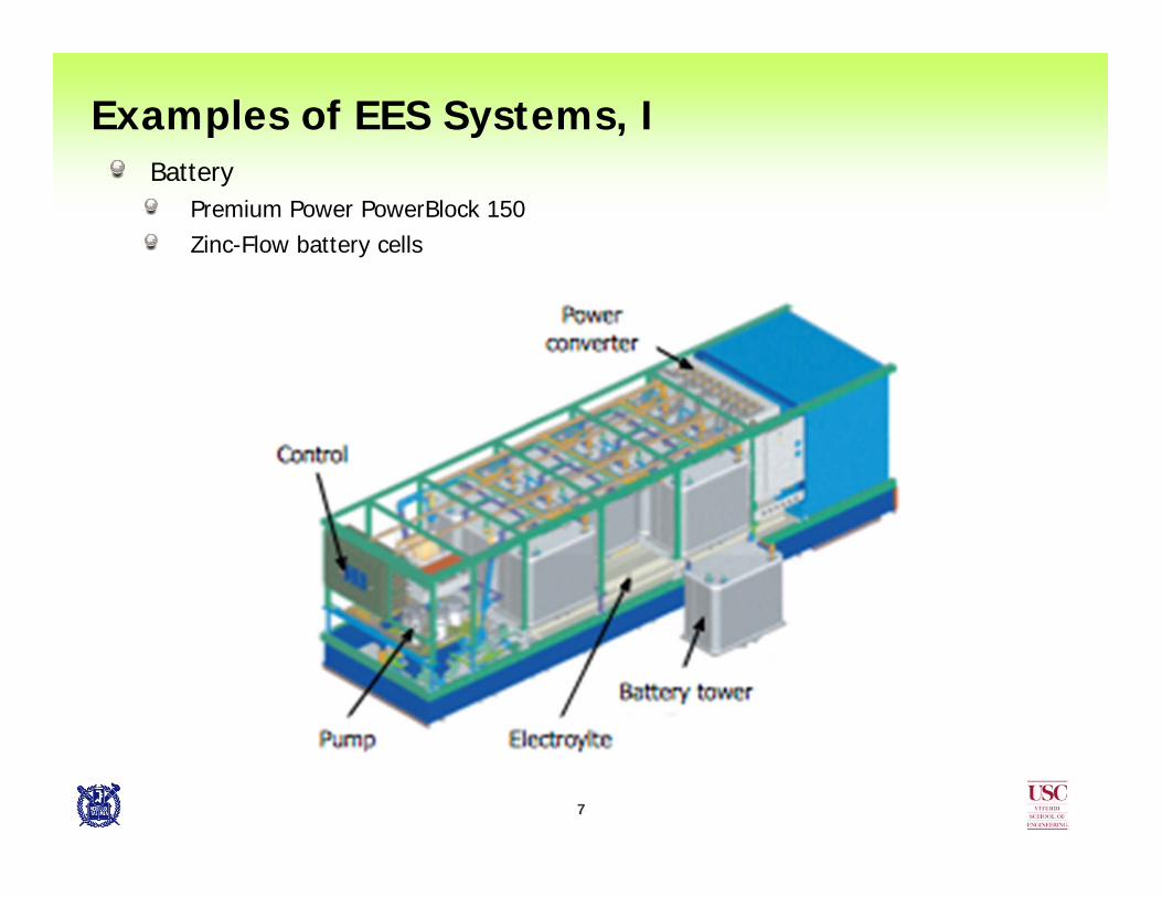
BatteryPremium Power PowerBlock 150Zinc-Flow battery cells
Examples of EES Systems, I

8
FlywheelSun Microsystems, ColoradoData center UPS’s
Examples of EES Systems, II

9
Examples of EES Systems, III
CAES (compressed air energy storage)Iowa Stored Energy Park, Iowa (planned)

10
Performance Metrics for EES systems
Cycle efficiency, cost per unit capacity, energy density, power capacity, cycle life, and environmental impact including end-of-life disposal costNo single type of EES element can simultaneously fulfill all the desired characteristics of a modern EES system
11
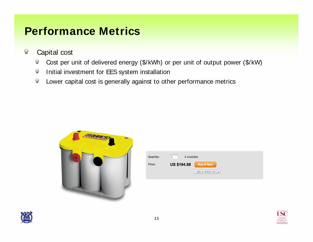
Performance Metrics
Capital costCost per unit of delivered energy ($/kWh) or per unit of output power ($/kW)Initial investment for EES system installationLower capital cost is generally against to other performance metrics

12
Performance Metrics, cont’d
Charging efficiencyRatio of energy delivered from the energy source to the EES element
Discharging efficiencyRatio of energy delivered from the EES element to the load
Cycle efficiencyProduct of charging and discharging efficienciesSignificantly affected by charging/discharging profiles and ambient conditionsExamples includes rate capacity effect and charge recovery effect

13
Performance Metrics, cont’d
Cycle lifeThe capacity or SOH (state of health) tends to gradually deteriorate due to irreversible physical and chemical changesDefined as the number of cycles an EES element can perform before its capacity drops to a specific percentage (60-80% typically) of its initial full-charged capacityStrongly dependent on the depth of discharge (DoD) before that element is rechargedLonger cycle life EES elements
Electrical, mechanical or thermal technologiesSupercapacitor, flywheel, thermal energy storage (TES) and cryogenic energy storage (CES), etc.
Shorter cycle life of batteriesDue to unavoidable chemical deteriorations
14
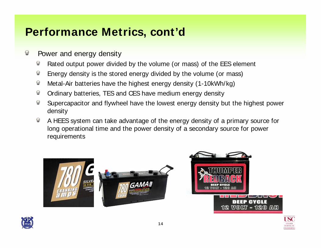
Performance Metrics, cont’d
Power and energy densityRated output power divided by the volume (or mass) of the EES elementEnergy density is the stored energy divided by the volume (or mass)Metal-Air batteries have the highest energy density (1-10kWh/kg)Ordinary batteries, TES and CES have medium energy densitySupercapacitor and flywheel have the lowest energy density but the highest power densityA HEES system can take advantage of the energy density of a primary source for long operational time and the power density of a secondary source for power requirements

15
Performance Metrics, cont’d
Self-discharge rateHow quickly an EES element will lose its energy when it simply sits on the shelfDetermined by the inner structure and chemistry, as well as ambient temperature and humidityOrdinary batteries can store energy reliably up to tens of daysLithium primary batteries can be stored 10 years on the shelfFlow batteries have very small self-discharge rate and thus are suitable for long-term energy storageSupercapacitors have large self-discharge rate and are useful for short-term energy storage for a maximum of several hours or a couple of days

16
EES Elements: Commercial Off-the-Shelf
Lead-acid batteryShort cycle life (500-800 cycles)Low energy density (30-50 Wh/kg)Poor low temperature performance and thus a thermal management system is requiredRelatively high power density (75-300 W/kg), able to supply high surge currentsMedium energy efficiency (70-90%)Low cost (100-200 $/kWh)Suitable in motor vehicles to provide the high current demand for automobile starter motorsUsed in large-scale commercial energy management systems

17
EES Elements, cont’d
NiCd batteryRelatively high energy density (40-60 Wh/kg or 50-150 Wh/L)Moderate cycle life (as high as 2,000 cycles)Relatively high self-discharge rate (10% per month)High cost (800-1,000 $/kWh)Undesirable environmental effect due to the use of toxic heavy metal
Specific energy 40–60 Wh/kg
Volumetric energy density 50–150 Wh/L
Specific power 150 W/kg
Charge/discharge efficiency 70%–90%
Self-discharge rate 10%/month
Cycle durability 2,000 cycles
Nominal cell voltage 1.2 V

18
EES Elements, cont’d
NiMH batteryEnergy density (60-80 Wh/kg) is twice as large as lead-acid batteries and 40% higher than that of NiCd batteriesCheaper to purchase than Li-ion batteriesSuffer from the memory effect, although much less pronounced than that in the NiCd batteriesRelatively high self-discharge rate (0.5-1% per day)High power density (250-1,000 W/kg)Due to the high power density, these batteries are widely used in high current drain consumer electronics, such as digital cameras with LCDs and flashlightsWidely used in hybrid electric vehicles such as the Toyota Prius, Honda Insight, Ford Escape Hybrid, etc.

19
EES Elements, cont’d
Li-ion batteryHigh energy density (100-250 Wh/kg or 250-360 Wh/L)High efficiency (almost 100%)Long cycle life (as high as 10,000 cycles)No memory effectLow self-discharge rate (0.1-0.3% per day)High cost (above 600 $/kWh)In many portable electronic devices and growing in military, electric vehicle, and aerospace applications

20
EES Elements, cont’d
SupercapacitorHigh cycle efficiency (almost 100%) and long cycle life (up to 1,000,000 cycles)Significantly high volumetric power density (above 100,000 W/kg) but low energy density (2.5-15 Wh/kg)Large self-discharge rate compared with ordinary batteries
About 20% energy may be lost per day
Suitable for energy storage with frequent charging/discharging cycles or periodic high current pulses. May be used in battery-supercapacitor hybrid systemsTerminal voltage variation whereby the terminal voltage is linearly proportional to its SOC (state of charge)
May affect conversion efficiency in the power converters connected to the supercapacitors
21
EES Elements, cont’d
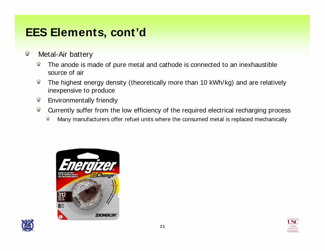
Metal-Air batteryThe anode is made of pure metal and cathode is connected to an inexhaustible source of airThe highest energy density (theoretically more than 10 kWh/kg) and are relatively inexpensive to produceEnvironmentally friendlyCurrently suffer from the low efficiency of the required electrical recharging process
Many manufacturers offer refuel units where the consumed metal is replaced mechanically

22
EES Elements, cont’d
Emerging technologiesCompressed air energy storage
Medium efficiency (70%)
Cryogenic energy storage (CES)No environmental burden (because of the use of liquid nitrogen or liquid air)Relatively high energy density (150-250 Wh/kg)Low capital cost and relatively long storage periodLow efficiency currently (40-50%)
http://www.matternetwork.com
http://www.engineering.leeds.ac.uk

23
Performance Comparison of EES Elements
EES Elements Capital cost ($/kWh) Cycle efficiency Cycle life
Lead-acid 100-200 70-90% 500-800
NiCd battery 800-1,000 70-90% 2,000
NiMH battery 450-1,000 66% 500-1,000
Li-ion battery 600-2,500 >90% 1,000-10,000
NaS battery 300-500 87% 2,500
Metal-Air battery 10-60 <50% 100-300
Supercapacitor 20,000-50,000 >90% 500,000-1,000,000
Flywheel 1,000-5,000 >90% 20,000+
High-temperature TES 30-60 30-60% -
CES 3-30 40-50% -

24
Performance Comparison, cont’d
EES Elements Self-discharge per day Energy density Power density
Lead-acid 0.1-0.3% 30-50 Wh/kg 75-300 W/kg
NiCd battery 0.2-0.6% 40-60 Wh/kg 150-300 W/kg
NiMH battery 0.5-1% 60-80 Wh/kg 250-1,000 W/kg
Li-ion battery 0.1-0.3% 100-250 Wh/kg 250-340 W/kg
NaS battery ~20% 150-240 Wh/kg 150-230 W/kg
Metal-Air battery Very small 1-10 kWh/kg -
Supercapacitor 20-40% 2.5-15 Wh/kg 100,000+ W/kg
Flywheel 100% 10-30 Wh/kg 400-1,500 W/kg
High-temperature TES 0.05-1% 80-200 Wh/kg -
CES 0.5-1% 150-250 Wh/kg 10-30 W/kg

25
Life time of each EES element
Total energy cost per day
Total amortized cost per daySum of the purchase price, setup/disposal costs, and energy usage cost per day
EES System: Amortized Cost

26
Switching Mode DC-DC Converter
Buck (step down) converterLower the output voltage compared to the input voltageLC filtering of the switching output Average output voltage is determined by the power switch’s turn-on duty ratio
Boost (step up) converterIncrease the output voltage compared to the input voltageAdd the energy stored in the inductor capacitorAverage output voltage is determined by the switch turn-off duty ratio

27
DC-DC Converter, cont’d
Inverted Buck-Boost converterInverted outputLow efficiency due to presence of the diodeSimple and easy to control
4-switch Buck-boost converterNon-inverted outputHigh efficiency Complex controlSynchronous switches replace the freewheeling diodeSelectively operated as a buck or a boost converter according to the input and output voltages

28
Constant Current Charger
Linear chargerCurrent regulator using power MOSFET in saturation modePrecise current control without noiseLow efficiency due to the IR loss in the MOSFET
Switching mode chargerCurrent feedback buck-boost converterProvide basic charging protocol and protection featuresSwitching noise70-80 % conversion efficiency

29
Constant current charger using high efficiency buck-boost converter moduleLinear technology LTM4607 buck-boost converter micro module
4-switch buck-boost topologyOn-chip power switchesVery high conversion efficiency: ~98%
Charger, cont’d

30
Charger, cont’d
Constant current charger using high efficiency buck-boost converter moduleVoltage and current feedback loop modificationsSafe and efficient charging operation

31
Charge Management Circuits
Battery/suepercapacitor chargerPower converter specialized for charging batteries or supercapacitorsCharge management for various cell configurations and multiple chemistryCombined charging schemes (e.g., constant voltage + constant current) for reliability and efficiency
Charger efficiency issueGenerally, batteries are charged by the AC power, and so conversion efficiency has not been a critical issueWhen a renewable power source such as a solar cell or fuel cell is used, power conversion efficiency should be taken into consideration

32
Charge Management Circuits: Summary
Bridge diode AC-DC rectifierMake DC to AC with diode bridge
Voltage regulatorZener-diode regulator
Regulate the voltage using breakdown voltage
Voltage regulator using OP-ampRegulate the voltage using the feedback loop
Three-terminal voltage regulatorWidely used in common DC power supplying circuit
Switching mode DC-DC converterBuck DC-DC converter
Step down the voltage according to the switching duty cycle, Dt
Boost DC-DC converterStep up the voltage according to the switching duty cycle, (1- Dt)
H-bridge DC-AC inverterMake DC to AC by alternatively switching the H-bridge

33
Charge Management Circuits, cont’d
Power converters and efficiencyEES systems involve AC-DC and DC-AC conversionsLow conversion efficiency directly results in a high operational costDesigning the power converters should consider operating cost (efficiency) as well as the implementation costThe energy efficiency of the power converters are affected by
Design such as switch resistance, inductor and transformer performanceOperational conditions such as input voltage, output voltage, load current, switching frequencyEnergy efficiency of an EES element is often measured under the best condition
1/25 C discharge rateBest temperature conditionWith brand new batteries

34
Charge Management Circuits, cont’d
Sources of power loss in a switching regulatorESR (Equivalent Series Resistance) of each component
I2R power dissipation in switch, inductor and etc.Dependent on the load current
Parasitic capacitances of MOSFET switching gatePower dissipation to drive two switchesIndependent of load current
Control circuitryPower dissipation for PWM control and miscellaneous circuitsIndependent of load current

35
Charge Management Circuits, cont’d
Conversion efficiency of a DC-DC converter by a power MOSFET configuration
36
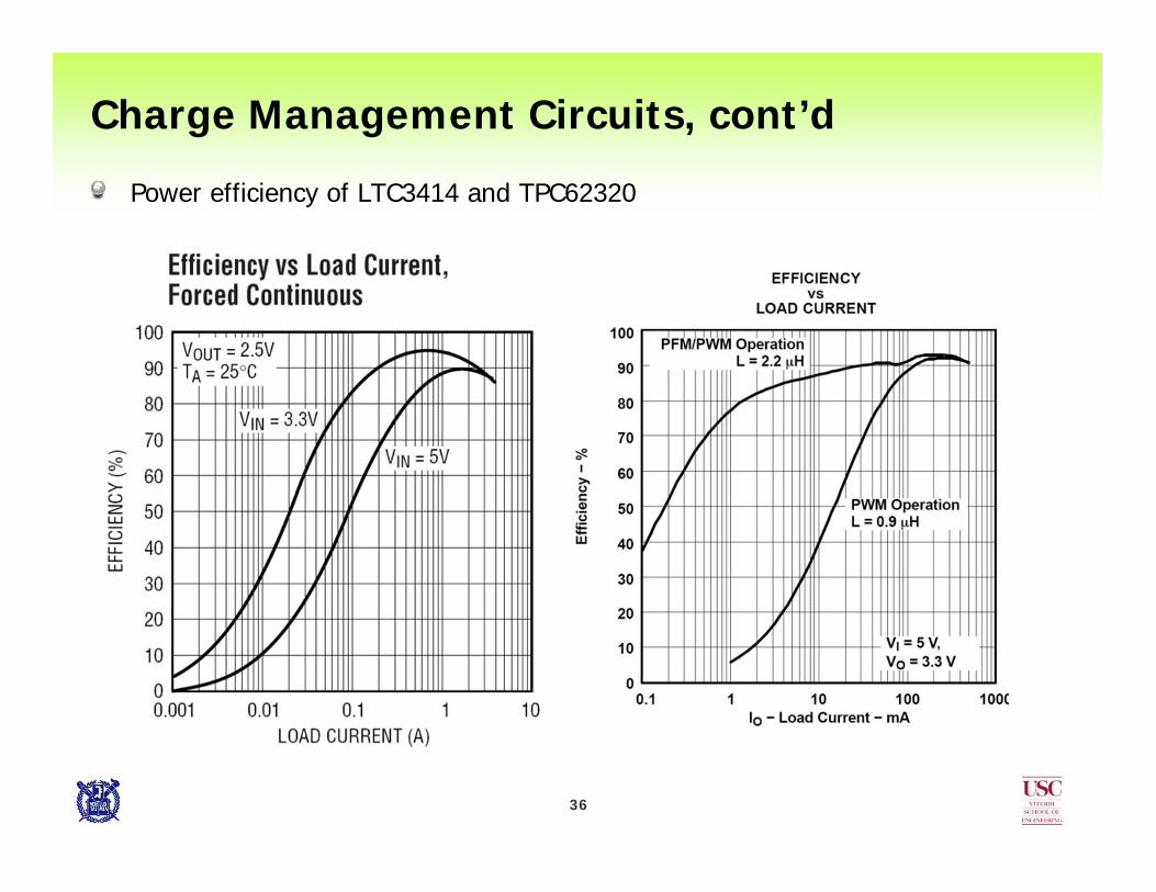
Charge Management Circuits, cont’d
Power efficiency of LTC3414 and TPC62320

37
Charge Management Circuits, cont’d
Switching charger power dissipationSum of the conduction, switching, and controller power losses
Conduction lossIR loss in the MOSFET switches, inductor, and ESR of the bulk capacitorProportional to the equivalent resistance of the components and output current
Switching lossMOSFET switch gate drive lossProportional to the input voltage, switching frequency, and gate capacitance
Controller lossStatic power dissipated by the switch controller
General characteristicsThe charger efficiency decreases when the input and output voltage difference is largeBoost converters are less efficient than buck converters
38
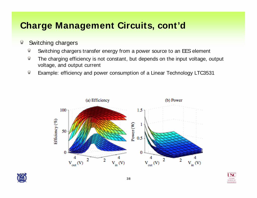
Switching chargersSwitching chargers transfer energy from a power source to an EES elementThe charging efficiency is not constant, but depends on the input voltage, output voltage, and output currentExample: efficiency and power consumption of a Linear Technology LTC3531
Charge Management Circuits, cont’d

39
Charging efficiency variation in supercapacitor chargingCharging efficiency variation should be considered when the input/output voltages are not constant
Example: input from solar cell and output to supercapacitor
Conventional MPPT (maximum power point tracking) techniques are not necessarily energy efficient here
Maximizing the charger input power may not maximize the charger output current
Charge Management Circuits, cont’d

40
Charge Management Circuits, cont’d
Monitoring and controlBMS (battery management system)
Maintains stability and sources of important information for the charge management policiesEstimates the SOC and SOH, controls the voltage, current, and cell balances (distributing SOC evenly across the bank), and provides diagnostics functionality
CAN, FlexRay network for monitoringSCADA (supervisory control and data acquisition) system for HCI

41
Hybrid Electrical Energy Storage (HEES) Systems
MotivationComputer memory hierarchy
No single type of memory, device can achieve short access time, high density, balanced read/write performance, low cost per bit, low power consumption, non-volatility, etc.
Concept of hybrid EES systemsEach EES element has different characteristics such as cycle efficiency, leakage current, cycle life, storage cost, and volumetric energy density, power rating, and so onNo single type of EES element can simultaneously fulfill all the desired characteristicsExploit the advantages of each EES element and hide its disadvantagesHybrid EES systems consist of both low unit cost (e.g., lead-acid batteries) and high unit cost (e.g., supercapacitors) EES elementsShould be minimized by allocating the amounts of low-cost vs. high-cost EES elements while meeting other performance constraintsDifferent types of energy storage elements can be organized in an appropriate storage hierarchy and reconfigured on the fly

42
HEES System Architecture

43
HEES System Architecture, cont’d
To provides enhanced cycle efficiency, extended cycle life for each element, increased energy storage capacity, and output power rating
Heterogeneous EES elementsGeneralized power migration busesHigh-efficiency power convertersOptimal charge management policies
Logically hierarchical, physically flat structure to shorten the charge transfer pathsThe architecture is closer to scratch pad memory rather than cache memory in that:
Both allocation and replacement policies are requiredFlat physical structure (cache is hierarchical)
44
HEES System Architecture, cont’d
Charge migration path can be a multiple power bus or a crossbar networkAllows optimal simultaneous migration operations
The optimal power bus voltage for each migration is a function of the EES elements and their SOCA shared power bus requires the same voltage level of all the power converters for simultaneous migration operations
Reconfigurability for enhanced cycle efficiencyEach EES bank consists of multiple homogeneous EES elements to meet certain voltage, power and capacity requirements maintaining balancing
Charging/discharging efficiency is a strong function of SOC as well as voltage and current levelsA fixed array structure cannot always guarantee desirable cycle efficiencyFor example, a supercapacitor bank may have very low terminal voltage with low SOC

45
HEES System: Charge Allocation (charging)
Charge allocation problem is to determine the destination EES banks that maximize the charging efficiencyCharging efficiency is dependent on
Type and SOC of the bankVoltage and current characteristics of the power sourceDegree of MPTT (maximum power transfer tracking) for the power source, and so forth
The most efficient EES bank changes over time as SOC changes during charging When the SOC of the destination EES has a significant change during the charging process, reconfiguration of the internal connections may be desirable

46
HEES System: Charge Replacement (discharge)
Charge replacement is to determine the most efficient EES banks which are capable of supplying electrical energy to a given load demandDischarging efficiency is dependent on
Rate capacity effectPower ratingTerminal voltage, and so on
The most efficient EES bank changes over time as SOC changes during discharging
47
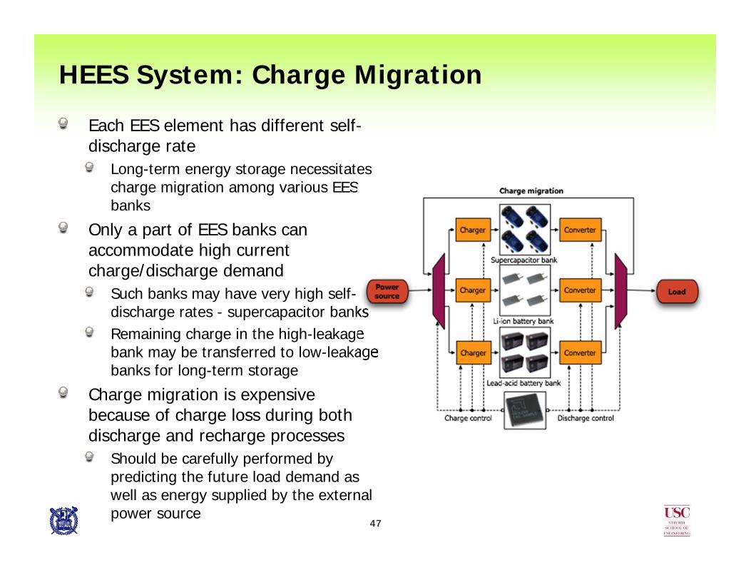
HEES System: Charge Migration
Each EES element has different self-discharge rate
Long-term energy storage necessitates charge migration among various EES banks
Only a part of EES banks can accommodate high current charge/discharge demand
Such banks may have very high self-discharge rates - supercapacitor banksRemaining charge in the high-leakage bank may be transferred to low-leakage banks for long-term storage
Charge migration is expensive because of charge loss during both discharge and recharge processes
Should be carefully performed by predicting the future load demand as well as energy supplied by the external power source

48
HEES System: Joint Charge Optimization
Charge allocation, replacement and migration cannot be optimized separately because of their sometimes conflicting natures as well as the strong couplings among them
For example charge migration may become inefficient in a system designed for optimal charge allocation
Thus the joint optimization of allocation, replacement and migration is a challenging, yet critical, problem

49
Amortized system cost optimization in a HEES system for large-scale energy storageMaximum power transfer tracking in a solar energy harvesting systemRate capacity effect mitigation in a system supporting widely varying load currents
Examples of Optimizing HEES Systems

50
Amortized cost optimization exampleDaily and weekly energy usage profiles
Example I: Amortized System Cost Optimization

51
Amortized cost optimization exampleAssumptions
Installation and disposal costs are included in the cost per capacityEnergy cost is 10 ¢/kWh
Two energy storage elements
Example I: Amortized System Cost Optimization
Criteria Battery Supercapacitor
Cyclelife 2,000 100,000
Cost per capacity ($/kWh) 1,000 40,000
Cycle efficiency 80% 100%
Self discharge rate (%/day) 0.1% 15%

52
Amortized cost optimization exampleConventional EES approaches
Battery-only EESSuffer from low cycle efficiency and short cycle life
Supercapacitor-only EESNot suitable for long-term storage
HEES approachUse batteries for weekly energy storage
Large capacitance: low cost-per-capacity requiredLong storage duration: low self-discharge rate required
Use supercapacitors for daily energy storageFrequent charge/discharge: high cycle efficiency and long cycle life required
Example I: Amortized System Cost Optimization

53
Amortized cost optimization example
Low storage cost due to battery cycle life enhancement using supercapacitors as daily energy storageLow energy cost due to high cycle efficiency of supercapaictors
Example I: Amortized System Cost Optimization
Cost ($/week) Battery-only EES Supercapacitor-only EES Hybrid EES
Storage cost 160.3 181.6 153.3
Energy cost 40.1 45.4 38.3
Total cost 200.4 227.0 191.6

54
Solar energy harvesting is a promising method for self-sustainable systemsHarvested energy is necessary to be stored in an EES system for stable power supply
Continuous operation in cloudy weather or at nightA rechargeable battery and/or supercapacitor is usedEnergy transfer involves energy loss
Example II: Solar Energy Harvesting System
55
Optimal solar energy harvesting systemMaximizing the harvested energy at the minimum costEnergy conversion efficiency should be maximized
Charger conversion efficiencySignificantly affected by the state of the energy source (PV module) and energy storage (supercapacitor)The environment and system state change over time, and maximizing the system-wide efficiency is non-trivialPrevious battery-based energy harvesting techniques may not be efficient for supercapacitors
No attempt to find the system-wide optimal design considering the energy source and storage for supercapacitors
For a given energy harvesting requirement, the minimum size of a PV cell array and the minimum capacity of a battery are typically considered
Solar Energy Harvesting Example, cont’d
56
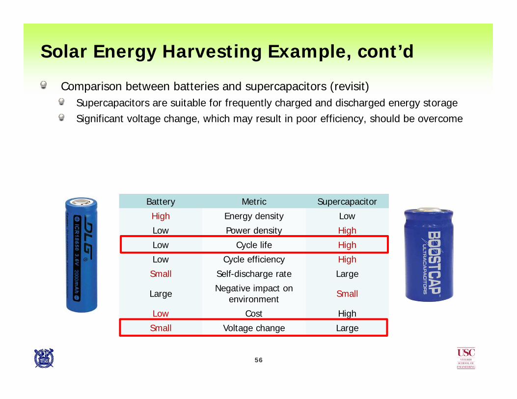
Comparison between batteries and supercapacitors (revisit)Supercapacitors are suitable for frequently charged and discharged energy storageSignificant voltage change, which may result in poor efficiency, should be overcome
Solar Energy Harvesting Example, cont’d
Battery Metric Supercapacitor
High Energy density Low
Low Power density High
Low Cycle life High
Low Cycle efficiency High
Small Self-discharge rate Large
Large Negative impact on environment Small
Low Cost High
Small Voltage change Large

57
Maximum power point tracking (MPPT) techniqueMaximizes the output power from the PV moduleDoes not guarantee the maximum energy accumulationCharger output power by the MPPT technique may be less than that by the MPTT technique
Three design considerationsPV cell configurationCharger selectionSupercapacitor configuration
Solar Energy Harvesting Example, cont’d

58
PV module configuration: voltage and current characteristics depend on series and parallel configuration
More PV cells in series: higher voltageMore PV cells in parallel: higher current
The minimum number (cost-optimal) of cells and their energy-optimal configuration should be derived
Solar Energy Harvesting Example, cont’d

59
MPTT problem statement and solutionGiven
Energy requirementSolar irradiance profileCharger efficiency dataUnit PV cell characteristic
FindOptimal PV module configuration (number of connected cells)Optimal supercapacitor capacitance
SolutionApproximate harvested energy for given configurationIteratively increase the number of PV cells
Charger design may also be optimization object to increase the energy efficiency (e.g., power switch, switching frequency, etc.)
Solar Energy Harvesting Example, cont’d

60
Solar Energy Harvesting Example, cont’d
Charger selectionCharger maximum output and current ratingIR loss and gate drive loss

61
Supercapacitor capacitance considerationSmaller capacitance: higher voltageLarger capacitance: lower voltage
Energy-optimal capacitance should be derivedCost of the supercapacitance is determined by the given energy requirement, not its capacitance
Solar Energy Harvesting Example, cont’d

62
Maximum charge power surfaceThe MPTT method maximizes the power into the supercapacitor at all timesThe maximum power transferred into the supercapacitor is a function of the irradiance level and the supercapacitor voltage
Solar Energy Harvesting Example, cont’d

63
Example III: High Efficiency for Variable Loads
Discharge with different constant current Discharge with constant and pulsed current
Rate capacity effect in batteriesUndeliverable charge according to the battery operating condition
Energy impactPower loss in the battery caused by battery internal resistance

64
Variable Load Support Example, cont’d
A typical load profile for military radio systemsAn EES system may be designed to be capable of handling a (variable) load of average power between 5 and 50 watts, which may also contain significant (up 100-watts) transient spikesThe EES system must handle both positive and negative transient load power pulses

65
Variable Load Support Example, cont’d
Parallel connectionConnect the battery and supercapacitor in parallelStraightforward solutionFiltering voltage fluctuationGodfrey Sikha and Branko N. Popov, Performance optimization of a battery–capacitor hybrid system, Journal of Power Sources 134 (2004) 130–138
Voltage and current responseParallel connection

66
Variable Load Support Example, cont’d
Constant-current charger-based hybrid architectureConstant-current charger
Separate the battery current from the load current Widely used for battery and supercapacitor managementSimple circuit implementation
Rate-capacity effect reductionMitigate current fluctuation
Converter efficiency Supercapacitor terminal voltage should be maintained in a high-efficiency range
Constant current hybridVoltage and current response
67
Variable Load Support Example, cont’d
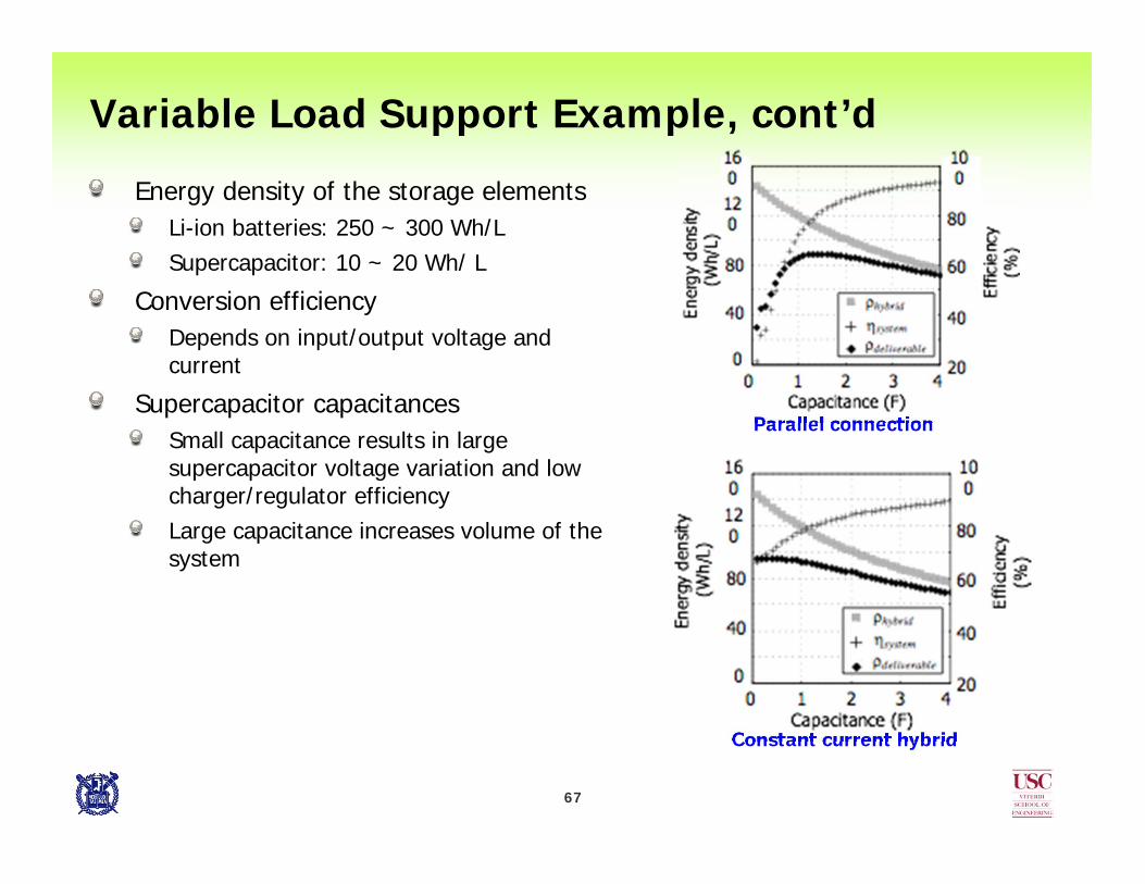
Energy density of the storage elementsLi-ion batteries: 250 ~ 300 Wh/LSupercapacitor: 10 ~ 20 Wh/ L
Conversion efficiencyDepends on input/output voltage and current
Supercapacitor capacitances Small capacitance results in large supercapacitor voltage variation and low charger/regulator efficiencyLarge capacitance increases volume of the system
Parallel connection
Constant current hybrid

6868
Variable Load Support Example, cont’d
Controller board
68

69
Variable Load Support Example, cont’d
BatteryLi-ion GP2N1051 cell2SP1 pack8.4 V 350 mAh
SupercapacitorNessCap ESHSR-0010C04S array2.5F, 10.8V
7.7 % deliverable energy gain
Parallel connection
Constant current hybrid

70
Variable Load Support Example, cont’d
Voltage and current waveformThe HEES system architecture shows smaller current fluctuation compared with the parallel connection
Parallel connection Constant current hybrid
71
Conclusions
Initial work on hybrid electrical energy storage (EES) systems by using a combination of various EES elements
No single EES element can fulfill all requirements of a modern EES system
Architectural consideration of the hybrid EES system based on the computer memory hierarchy (scratch pad memory) concept
Setup the concept of key EES management operationsCharge allocation, replacement, and migration
HEES optimization examplesPeak shavingMaximum power transfer trackingRate capacity mitigation
Future workSystematic (mathematical) approaches for holistic optimization of a HEES system
Simultaneous optimization of charge allocation, replacement and migration processes