HV1/140A SPERRE - Suppliers Of Marine & Industrial Spare Parts · Instruction book for compressor...
31
HV1/140A INSTRUCTION MANUAL AIR COMPRESSOR GB SPERRE November 2002
Transcript of HV1/140A SPERRE - Suppliers Of Marine & Industrial Spare Parts · Instruction book for compressor...
HV1/140A
INSTRUCTION MANUAL AIR COMPRESSOR
GB
SPERRE November 2002

Instruction book for compressor type HV1/140A
PREFACE Sperre has produced this instruction manual in order to provide users of its compressor equipment with information about the compressor’s construction and operation, as well as basic information about inspection and maintenance. It is important that the operator should familiarise himself with the contents of this instruction manual, so as to ensure that installation, use and maintenance work is carried out in a correct and safe manner from the outset. The maintenance intervals and individual technical data are average values based on experience, and may vary, depending on the compressor’s operational parameters. The supplier accepts no responsibility for damage resulting from careless operation or inadequate maintenance. Keep the compressor in good mechanical condition, and remember that preventive maintenance of the equipment reduces the danger of damage and unnecessary operational interruptions. Sperre reserves the right to modify details without prior warning.
Ellingsøy, September 2005 Sperre Industri A/S
Page 1
Instruction book for compressor type HV1/140A
CONTENTS Page 1. Personal safety ........................................................................ 3 2. About the compressor ............................................................ 4 2.1 Construction ....................................................................... 4 2.2 Safety equipment ............................................................... 7 3. Installation and operation ....................................................... 8 3.1 Installation instructions ....................................................... 8 3.2 Cooling water system......................................................... 8 3.3 Start-up .............................................................................. 9 3.4 Operation ........................................................................... 9 3.5 Stopping and preparation for downtime ............................. 10 4. Operational failures................................................................. 11 5. Inspection and maintenance .................................................. 13 5.1 Maintenance intervals ........................................................ 13 5.2 Valves ................................................................................ 14 5.3 Lubrication system ............................................................. 15 5.4 Bearings ............................................................................. 16 5.5 Pistons and piston rings ..................................................... 17 5.6 Elastic coupling .................................................................. 18 5.7 Coolers............................................................................... 19 5.8 Filters ................................................................................. 19 6. Technical data.......................................................................... 20 6.1 Cooling water capacities .................................................... 20 6.2 Recommended pressures and temperatures ..................... 20 6.3 Torque................................................................................ 20 6.4 Clearances ......................................................................... 21 6.5 Piston rings ........................................................................ 21 6.6 General data ...................................................................... 21 7. Ordering spare parts ............................................................... 22 8. Parts lists ................................................................................. 23 8.1 Compressor parts............................................................... 23 8.2 Valve parts ......................................................................... 24 9. Part drawings........................................................................... 25 Compressor ............................................................................... 25 Valves........................................................................................ 29
Page 2

Instruction book for compressor type HV1/140A
1. PERSONAL SAFETY The installation, operation and maintenance of the compressor must be carried out by trained personnel who are familiar with the contents of this instruction manual. The compressor must only be used to compress air. Unauthorised remodelling or modification of the compressor may result in a safety hazard, and are not permitted. Before any form of work is commenced on the compressor the electrical power must be turned off at the starter panel and at the main switchboard and the switch on the main switchboard must be marked with a notice indicating that repair work is in progress. The discharge valve of the compressor must be closed, and the pressure must be released in all pressurised parts of the compressor. The safety valves for LP and HP air, the bursting disc in the water mantle and any other safety equipment must be inspected regularly. Damaged components should be replaced with new, original parts. Adjustment of the safety valves shall only be carried out by authorised personnel. The compressor must never be used if the safety equipment is defective.
Page 3

Instruction book for compressor type HV1/140A
2. ABOUT THE COMPRESSOR 2.1 Construction The compressor described in this instruction manual is constructed as a one cylinder, two stages double action water cooled compressor. The principles of its construction are illustrated in Figures 2.1 and 2.2. Fig. 2.1 Construction principles
Page 4

Instruction book for compressor type HV1/140A Instruction book for compressor type HV1/140A
Page 5
Page 5
Instruction book for compressor type HV1/140A
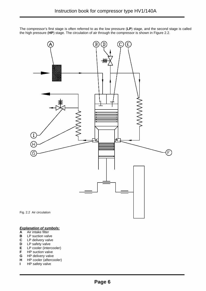
The compressor’s first stage is often referred to as the low pressure (LP) stage, and the second stage is called the high pressure (HP) stage. The circulation of air through the compressor is shown in Figure 2.2. Fig. 2.2 Air circulation Explanation of symbols: A Air intake filter B LP suction valve C LP delivery valve D LP safety valve E LP cooler (intercooler) F HP suction valve G HP delivery valve H HP cooler (aftercooler) I HP safety valve
Page 6

Instruction book for compressor type HV1/140A
The big end bearing and gudgeon pin bearing are pressure lubricated by means of a gear pump connected directly to the end of the crankshaft. The main bearings are roller bearings, and they are lubricated by the oil splashing in the crank case. The cooler tubes are rolled into the compressor’s cylinder block. The LP cooler cools the compressed air after first-stage compression, while the HP cooler cools the compressed air after second-stage compression. The intake and discharge of the cooling water is arranged so that the water circulates through the cylinder block and ensures effective cooling of the air and the compressor’s cylinder walls. The compressor increases the pressure of air from atmospheric pressure to a specified pressure, up to a maximum of 35 bar. The compressor is normally fitted with an electric motor or other source of motive power on a well-braced baseplate, with a flexible coupling between the compressor and the motor. All compressors are test run before delivery from the factory, and all installations with motor will have been correctly aligned. This compressor, which is used to produce pressurised air for compressed air tools and instruments as well as starting air, satisfies the requirements of the certification companies. 2.2 Safety equipment The compressor is fitted with safety valves after first-stage and second-stage compression. These safety valves are pre-adjusted upon delivery of the compressor to suit the working pressure specified by the customer, ensuring that the pressure does not exceed the limit for which the compressor and compressed air system are dimensioned. A bursting disc is mounted on the cylinder block cooling water mantle, which ruptures if the coolant chamber is subjected to abnormally high pressure. The bursting disc must only be replaced with original plates supplied by the compressor supplier. Important: The safety valves, bursting disc and any other safety equipment must be inspected regularly. Damaged components should always be replaced with original parts. Adjustment of the safety valves shall only be carried out by authorised personnel. The compressor must not be used if the safety equipment is defective. The compressor’s automatic control system includes a pressure switch which stops the compressor if the pressure of the lubricating oil falls below a specified minimum level.
Page 7

Instruction book for compressor type HV1/140A
3. INSTALLATION AND OPERATION 3.1 Installation instructions All compressor deliveries are accompanied by documentation of the installation’s dimensions and mounting points. The documentation will also include installation instructions, showing the recommended assembly of equipment and pipe connections. To achieve problem-free operation, it is important that the base-plate is sufficiently rigid and free from vibrations caused by other machinery. The base of the compressor must lie flat on the base-plate. After installation of the compressor, the alignment between the compressor and its drive motor should be checked as described in Section 5.6. (Even if the installation is mounted on vibration dampers, it is recommended that the alignment is checked after installation.) The cooling water pipes must be installed in such a way the air pockets cannot occur. The compressor installation should not be closely surrounded by other equipment which would hinder maintenance work. 3.2 Cooling water system A reliable and adequate cooling water supply is important for the functioning and life-expectancy of the compressor. The necessary cooling water capacities are specified in Table 6.1, and apply both to seawater and freshwater cooling. Whether the compressor is connected to a central cooling system or is equipped with a separate cooling water pump, it is important to ensure that cooling water circulation is maintained, and the indication of cooling water pressure by the manometer alone is not sufficient proof of this. It is recommended that the cooling water circulation be shut off when the compressor is not running, to avoid the precipitation of condensation in the crankcase. Too low temperature of the cooling water entering the compressor may lead to an increase in internal condensation, and if this occurs, the temperature of the cooling water should be increased. If it is not possible to increase the temperature, for example by recirculation, condensation formation may be reduced by reducing the amount of cooling water within the limiting values specified in Table 6.2. A thermometer is mounted in the cooling mantle on the cylinder head to monitor the cooling water temperature.
Page 8
Instruction book for compressor type HV1/140A
3.3 Start-up In connection with the first start-up or after prolonged downtime, the following procedure should be used: A Check oil level. B Check that the oil does not contain water or other substances which will impair its quality. C Check the compressor valves and apply a little oil to the cylinders. D Turn over the compressor by hand, removing the suction valve load by means of the manual unloader. (Set
the lever in the vertical position.) E Check the cooling water circulation. F Check that the non-return valve between the compressor and the air reservoir is open. G Set the manual drain valves in the open position. H Start the compressor. I If everything functions correctly, the drain valves and the unloader should be set to the operating positions.
(Set the unloader lever in the horizontal position.) The compressor should be allowed to run for a few minutes before subjecting it to maximum working pressure.
3.4 Operation Under normal operation the pressure and temperatures should be as specified in Table 6.2. Minor deviations may exist for some of the values which are directly influenced by conditions at the working location. The operation of the compressor is normally monitored by the starter installation’s automated system, which provides, for example, pressure switch monitoring of the lubricating oil pressure and thermostatic monitoring of the cooling water temperature and air temperature. However, it is recommended that the operation and automatic functions of the compressor is inspected regularly. Under any operating conditions, condensation will precipitate from the compressed air in the HP cooler of the compressor. In areas of high atmospheric humidity it is recommended that the solenoid drain valve is opened periodically during operation (for example two seconds of draining every five minutes). It is necessary to install a water separator in the pipe system between the compressor and the air receiver, to separate most of the water from the air before it enters the air receiver. In areas of high atmospheric humidity, condensation may also occur in the LP cooler. It is important to prevent this as any water will follow the air flow into the high pressure cylinder, where some of the water will pass the piston rings and into the crankcase. Water separation in the LP cooler may be reduced by increasing the c.w. temperatures, but not more than specified in table 6.2. It can also be reduced by installing a drain trap on the LP drain outlet, to constantly remove any water that is trapped inside the LP cooler chamber.
Page 9
Instruction book for compressor type HV1/140A
3.5 Stopping To stop the compressor manually for short periods, the following procedure should be used: A Flip the compressor’s manual unloader to the vertical position to unload the LP suction valve. B Open the drain valves. C Stop the compressor. When stopping the compressor before prolonged downtime, use the following procedure: A Drain of old lub. oil, clean the crankcase sump and fill with new oil. B Apply a suitable corrosion inhibiting oil to the compressor valves, non-return valves, cylinder walls and
open surfaces of the crankshaft. C If there is a danger of frost, drain the cooling water. D Set the manual unloader in the horizontal position so that there is no load on the compressor’s suction
valve. E Turn over the compressor by hand once a week. F The starter panel and other electrical equipment must be similarly protected against corrosion damage.
Page 10

Instruction book for compressor type HV1/140A
4. OPERATIONAL FAILURES Some of the faults which may occur during operation are summarised below: Fault symptom Possible cause Remedy
Dirty, worn or damaged valves.
Inspect and clean all valves. Replace defective parts.
Piston rings have stuck in the ring grooves, or are damaged/broken.
Disassemble the rings. Clean grooves and rings and replace defective parts.
Leaking safety valve. Replace safety valve. Leaking gasket between cylinder and cylinder head. Replace gasket.
Leaking gasket between cylinder and crank case. Replace gasket.
A The compressor has poor capacity and/or does not produce full pressure.
Clogged air filter. Clean filter.
HP valve damaged or dirty. Inspect and clean valves and replace defective parts.
Composite piston rings between HP and LP compression chamber are damaged.
Replace piston rings.
Leaking gasket - HP valve. Replace gasket. Leaking gasket between cylinder and cylinder top. (Air leaknig from HP channel into LP cylinder).
Replace gasket.
B LP safety valve blows.
LP safety valve defective or damaged. Replace safety valve.
Stop valve in the air line is closed. Open the stop valve.
Clogged non-return valve. Remove and clean non-return valve. Replace defective parts. C HP safety valve blows.
HP safety valve defective or damaged. Replace safety valve.
Coke deposits due to compressor overheating.
Check cooling water circulation and temperature. Inspect and if necessary clean coolers.
Polluted intake air. Inspect intake filter.
Poor lubricating oil.
Change oil grade. (See Section 5.3 for recommended oil grades.) The compressor should only be run on Synthetic lub. oil !
D Valves need overhauling too often.
Valve clamp bolts not tightened enough.
Tighten the clamp bolts to the correct torque. (See table 6.3).
Defective bearings. Inspect bearings and check clearances.
Low oil level or condensate mixed in oil.
Drain and clean crankcase sump, fill with new oil. E
Overheating and/or abnormal noise in crankcase. Damaged main roller
bearings. Check bearings. Replace defective parts.
Incorrect fitting of piston or crosshead bearing.
Replace defective parts, check piston clearances, ring clearances and crosshead bearing. F
Piston overheating and scuffing. Cooling malfunction. Check cooling water circulation
and temperature.
Page 11

Instruction book for compressor type HV1/140A
Worn piston rings. Replace piston rings. G Increased oil consumption. Leakage. Check the exterior of the
compressor.
Defective or worn HP piston rings.
Remove and check piston and if necessary replace defective piston rings. H
Oil passsing through crankcase ventilation to the air inlet. Leaking gasket between
cylinder and crank case. Replace gasket.
Cooling water pressure too high.
Check that pressure is within the recommended limits (See Table 6.2). I Ruptured bursting disc.
Pressure pulses in cooling water system.
Determine what is causing pulses and eliminate.
J Worn rubber element in the coupling between compressor and motor.
Poor alignment of compressor and motor shafts.
Correct alignment of coupling. (See Section 5.6).
Page 12

Instruction book for compressor type HV1/140A
5. INSPECTION AND MAINTENANCE 5.1 Maintenance intervals The maintenance intervals set out below are intended as guidance for normal maintenance. Since the operating conditions of the compressor may vary strongly according to the working location, it is important that the periods used are adapted to the experience of the individual operator.
Routine Maintenance period
Inspect Overhaul Replace
A After first 200 operating hours – Bolts in base-plate
Change oil and clean crankcase with lint-free cloth before filling with new oil.
B Daily
– Lub. oil pressure – Oil level – Cooling water
circulation and temperatures
– Automatic functions – Draining of
condensation in sump
C Every 500 hours – LP valve – HP valve – Bolts in base-plate
Defective parts
D Every 1000 hours
– Cylinder through valve openings
– Pipe connections – Safety valves – Bursting plate in
cooling water jacket
– Oil filter – Clean air filter
Change oil and clean crankcase with lint-free cloth before filling with new oil.
E Every 2500 hours
– Piston and cylinder walls
– Pistons, bolts and piston rings
– LP delivery valve – HP delivery valve Piston rings
F Every 5000 hours – Flexible coupling – Clean coolers LP delivery valve HP delivery valve Defective parts
G Every 10000 hours
– Crankshaft bearings – Main bearing – Crosshead bearing – Oil pump
Defective parts
Only original parts should be used when replacing. Please see Chapter 7, regarding ordering spares. Important: Before any form of work is commenced on the compressor the electrical power must be turned off at the starter panel and at the main switchboard. The switch on the main switchboard must be marked with a notice indicating that repair work is in progress. See Chapter 1. PERSONAL SAFETY
Page 13

Instruction book for compressor type HV1/140A
5.2 Valves Important: The valves are an essential part of the compressor and it is important for operational safety that all parts have the correct material specifications and machining tolerances. Even the smallest defect in a valve component may lead to overheating and consequent damage. The supplier accepts no responsibility for damage to the compressor resulting from the use of non-original parts. The spare part documentation shows each valve both assembled with an individual part number and disassembled with part numbers for the individual components. After overhaul or renewal of parts, the assembly should be performed in the order shown in the diagram of the disassembled valve. When assembling valves, use the correct tightening torque for greased nuts and valve bolts as indicated below:
Dimension Minimum torque [Nm]
Maximum torque [Nm]
M10 20 24 M12 35 43 M14 56 68 M16 88 108
Important: When inspecting the valves, loosen the clamp bolts on the valve cover before removing the cover. Following inspection and any overhaul of the valves, it is extremely important that the clamp bolts, that retain the valve in it’s seat, is tightene to the torque specified in Table 6.3. Valve overhaul and maintenance The performance and safety of the compressor depends upon the regular and effective maintenance of the valves. We therefore recommend that the following guidelines are followed: A When cleaning the valve externally for subsequent disassembly, never apply a vice directly to the valve
when loosening the nut on the centre bolt. A clamp jig for this purpose to fit all valves can be supplied by Sperre upon enquiry. A simple temporary clamp may be made by fixing two rods in a vice fitting the outer seat grooves of the valve.
B Thoroughly inspect and clean all valve components.
NB! Keep sharp objects away from sealing surfaces and plate parts. C Replace any parts which are worn or show even faint scratches. Check all fixing pins. The maximum wear
tolerance is 10% of the total thickness of a part. D If a spring or spring plate in a valve is weakened all the springs must be replaced, since damage may result
if some springs are installed loger than others. It is recommended that all springs be replaced after approximately 5000 operating hours, even if they do not appear damaged.
E The valve gaskets shoould be replaced every time the valve is removed from the compressor.
Most valves have pre-drilled holes for the fixing pins and spare holes for new pins. The fixing pins may be knocked out with a suitable tool. If it is impossible to remove a broken pin, use a spare hole.
F When removing a valve centre bolt, drill out the locking pin after first marking the locating point in the centre
of the pin with a centre punch. Then remove the centre bolt. After reassembling the bolt, a hole must be drilled for the locking pin so that this can be knocked firmly into place and then the ends opened up to prevent the pin from falling out.
G After replacing the fixing pins in their respective holes in the valve seat and/or valve cover, check that the
protruding end of the pins do not touch the opposing parts.
Page 14

Instruction book for compressor type HV1/140A
NB! Use only original spare parts. The valve nut should always be replaced with a new one after disassembly of a valve. Never re-
use the old nut. Rebuilding the valve requires accuracy and care. Use the correct number of parts and make sure that the various parts are located correctly. Compare them with the parts documentation to ensure that the correct number of parts is used. 5.3 Lubrication system The lubricating oil pump is a gear pump and will normally tolerate long operating times without overhaul. The pump is driven directly from the end of the crankshaft, and the oil pressure is regulated by means of a bypass valve. When inspecting, loosen the mounting flange and withdraw the pump. The compressor is not fitted with a lubricating oil filter. Important: Condensation collection in the crankcase can be a serious problem under certain operating conditions, and it is important that the operator regularly checks the compressor for condensed water in the lubricating oil. (See also Sections 3.2 and 3.4). If the lubricating oil does not emulsify with the condensation water, it may separate and sink to the bottom of the crank case where the lub. oil pump inlet is located. Due to the compressors sensitivity to coke deposits, the compressor should only be run on synthetic oil brands. The choice of lubricating oil is very important for reliable operation. The supplier has tested several oil types and the list below show recommended oil brands.
Synthetic oil
BP ENERSYN RX 100 CASTROL AIRCOL SN 100
CHEVRON HD COMPR. OIL 100 DAPHNE MARINE COMPRESSOR 100
BARELF AL 100 ESSO / EXXON ZERICE S 100
ESSO / EXXON SYNTESSTIC 68 MOBIL RARUS 827
NIPPON OIL CO. FAIRCOL SA100 STATOIL COMPWAY S 100
TEXACO CETUS DE 100 SHELL CORENA AP 68
ANDEROL 555 Further information on lubricating oils may be obtained upon enquiry from Sperre Industri AS, or from the oil manufacturers.
Page 15

Instruction book for compressor type HV1/140A
5.4 Bearings The big end bearing is a replaceable, two-piece sleeve bearing. The main bearings are roller bearings. The crosshead bearing are a one-piece sleeve bearing which are pressed into the connecting rod. Tolerances and clearances for the crankshaft, frame and crosshead bearings are listed in Table 6.4. All the sleeve bearings are pressure lubricated. Following inspection or replacement of the big end bearing, it is important to ensure that the bearing bushes do not pinch the crankshaft. It should be possible to turn over the compressor by hand. New two-piece bearings are treated with a running-in coating. Assembling a crosshead bearing liner on a connecting rod:A Remove old liner sing a hydraulic press. uB Push in new liner. C After assembly of the bearing bush, a hole must be drilled for the oil supply and locking screw.
Drill diameter: 6.8 mm. D The hole for the locking screw must have M8 thread. Fig. 5.1 Assembling crosshead bearing liner
Page 16
Instruction book for compressor type HV1/140A
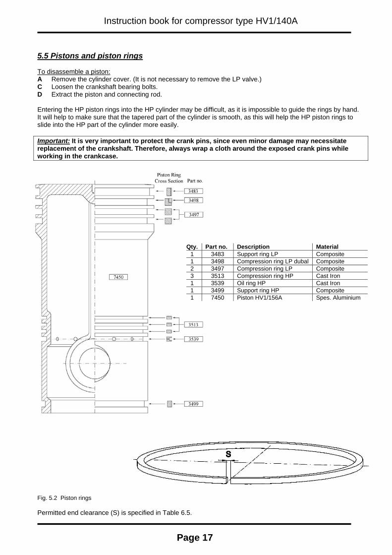
5.5 Pistons and piston rings To disassemble a piston: A Remove the cylinder cover. (It is not necessary to remove the LP valve.) C Loosen the crankshaft bearing bolts. D Extract the piston and connecting rod. Entering the HP piston rings into the HP cylinder may be difficult, as it is impossible to guide the rings by hand. It will help to make sure that the tapered part of the cylinder is smooth, as this will help the HP piston rings to slide into the HP part of the cylinder more easily. Important: It is very important to protect the crank pins, since even minor damage may necessitate replacement of the crankshaft. Therefore, always wrap a cloth around the exposed crank pins while working in the crankcase.
Qty. Part no. Description Material1 3483 Support ring LP Composite 1 3498 Compression ring LP dubal Composite 2 3497 Compression ring LP Composite 3 3513 Compression ring HP Cast Iron 1 3539 Oil ring HP Cast Iron 1 3499 Support ring HP Composite 1 7450 Piston HV1/156A Spes. Aluminium
Fig. 5.2 Piston rings Permitted end clearance (S) is specified in Table 6.5.
Page 17
Instruction book for compressor type HV1/140A
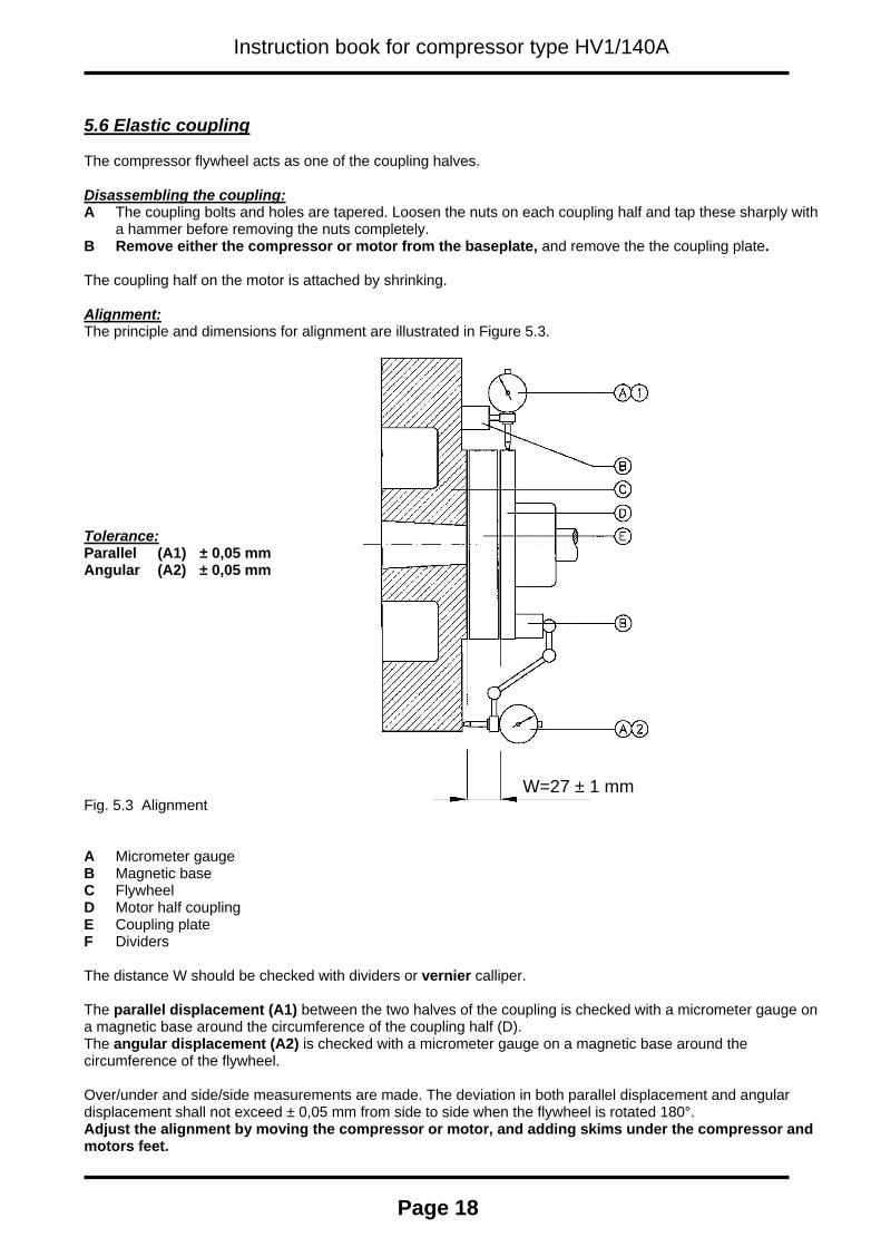
5.6 Elastic coupling The compressor flywheel acts as one of the coupling halves. Disassembling the coupling: A The coupling bolts and holes are tapered. Loosen the nuts on each coupling half and tap these sharply with
a hammer before removing the nuts completely. B Remove either the compressor or motor from the baseplate, and remove the the coupling plate. The coupling half on the motor is attached by shrinking. Alignment: The principle and dimensions for alignment are illustrated in Figure 5.3. Tolerance: Parallel (A1) ± 0,05 mm Angular (A2) ± 0,05 mm W=27 ± 1 mm Fig. 5.3 Alignment A Micrometer gauge B Magnetic base C Flywheel D Motor half coupling E Coupling plate F Dividers The distance W should be checked with dividers or vernier calliper. The parallel displacement (A1) between the two halves of the coupling is checked with a micrometer gauge on a magnetic base around the circumference of the coupling half (D). The angular displacement (A2) is checked with a micrometer gauge on a magnetic base around the circumference of the flywheel. Over/under and side/side measurements are made. The deviation in both parallel displacement and angular displacement shall not exceed ± 0,05 mm from side to side when the flywheel is rotated 180°. Adjust the alignment by moving the compressor or motor, and adding skims under the compressor and motors feet.
Page 18
Instruction book for compressor type HV1/140A
5.7 Coolers It is important for correct operation of the compressor that the LP and HP coolers are kept clean from coke deposits and deposits from the cooling water. Inadequate cooling will result in a higher temperature of the compressed air, which will cause the progressive formation of coke. The pipes are attached to the cylinder block at each end by rolling. If a cooler pipe show any sign of corrosion or wear, it should be replaced. This can be done by drilling out most of the wall thickness in the end part of the tube. The remaining pipe thickness will not be strong enough to keep the tube in the cylinder block, and it can be punched out with a hammer and a punch rod. It is necessary to use a special drill and puch rod to remove the tubes, and these can be purchased from Sperre. In addition it is necessary to use a special roller tool to fix the new tube in the cylinder block. This can also be purchased from Sperre. 5.8 Filters The air filter is cleaned using a high quality degreasing agent. Clean the filter with compressed air and apply a thin layer of compressor oil.
Page 19

Instruction book for compressor type HV1/140A
6. TECHNICAL DATA 6.1 Cooling water capacities Speed [rpm] 725 875 975 1150 Cooling water volume at 7-15 bar g working pressure [l/min] 9 10 11 13 Pressure drop across compressor [mm w.c.] 90 140 200 280 Cooling water volume at 15-35 bar g working pressure [l/min] 11 14 15 18 Pressure drop in compressor [mm w.c.] 140 220 350 440
6.2 Recommended pressures and temperatures Recommended minimum inlet temperature, cooling water 30°C Recommended maximum inlet temperature, cooling water 60°C Recommended cooling water differential temperature, inlet/outlet 10 - 15°C Recommended cooling water pressure 0,5 – 3,0 bar g Recommended oil pressure for warm compressor 2,0 bar g Recommended set point, oil pressure switch 0,8 bar g Normal first stage working pressure at 0 -10 bar discharge pressure 1,5 – 5,0 bar g Normal first stage working pressure at 10 - 35 bar discharge pressure 5,0 – 8,0 bar g Maximum working pressure 35 bar g Low Pressure safety valve set point 9 bar g High Pressure safety valve set point 5% above working pressure Normal temperature at air outlet 30 - 65°C
6.3 Torque Component Threads Torque [Nm] Comments Cylinder head M20 196 Valve cover, HP and LP M16 147 Valve clamp bolts, HP M20 117 Unbrako Valve clamp bolts, LP M12 78 Cap nuts, HP valve M20 98 Big end bearing bolts 1/4" BSP 88 -107 Crankcase end cover (bearing housing) M10 39 Cylinder block/crankcase M22 245 Crankcase inspection hatch M10 39 Cleaning hatch, air filter hatch M12 78
Page 20

Instruction book for compressor type HV1/140A
Page 21
6.4 Clearances Suction valve, LP, lifting height 1,2 mm Discharge valve, LP, lifting height 1,2 mm Suction valve, HP, lifting height 1,1 mm Discharge valve, HP, lifting height 1,1 mm Clearance, LP cylinder/piston 2,4 - 2,7 mm Clearance, HP cylinder/piston 1,3 - 1,5 mm Clearance, piston/cylinder head 1,0 - 1,8 mm Clearance, big end bearing 0,08 - 0,11 mm Clearance, gudgeon pin bearing 0,02 - 0,05 mm
6.5 Piston rings End clearance
Part no. Quantity Min. Max. Support ring (composite material) – LP 3483 1 3,9 4,45 Dubbal ring (composite material) – LP 3498 1 5,4 6,2 Compression ring (composite material) – LP 3497 2 5,4 6,2 Compression ring (metal) – HP 3513 3 0,45 0,65 Oil drain ring (metal) – HP 3539 1 0,45 0,65 Support ring (composite material) – HP 3499 1 3,5 4,0
End clearances (S) apply to new rings in new cylinders. Please see chapter 5.5 Pistons and piston rings for complete piston ring setup. 6.6 General data Number of cylinders 1 (stepped) LP piston diameter 140 mm HP piston diameter 126 mm Stroke 100 mm Crank pin diameter 63 mm Gudgeon pin diameter 40 mm Number of LP valve units 1 Number of HP valve units 1 Crank case oil capacity 4,0 litres
Instruction book for compressor type HV1/140A
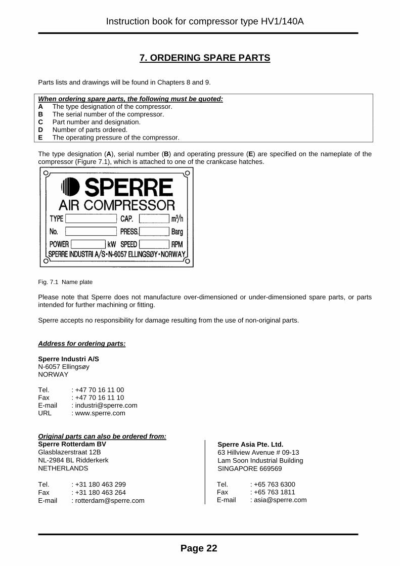
7. ORDERING SPARE PARTS Parts lists and drawings will be found in Chapters 8 and 9. When ordering spare parts, the following must be quoted:A The type designation of the compressor. B The serial number of the compressor. C Part number and designation. D Number of parts ordered. E The operating pressure of the compressor. The type designation (A), serial number (B) and operating pressure (E) are specified on the nameplate of the compressor (Figure 7.1), which is attached to one of the crankcase hatches.
Fig. 7.1 Name plate Please note that Sperre does not manufacture over-dimensioned or under-dimensioned spare parts, or parts intended for further machining or fitting. Sperre accepts no responsibility for damage resulting from the use of non-original parts. Address for ordering parts: Sperre Industri A/S N-6057 Ellingsøy NORWAY Tel. : +47 70 16 11 00 Fax : +47 70 16 11 10 E-mail : [email protected] : www.sperre.com Original parts can also be ordered from: Sperre Rotterdam BV Glasblazerstraat 12B NL-2984 BL Ridderkerk NETHERLANDS Tel. : +31 180 463 299 Fax : +31 180 463 264 E-mail : [email protected]
Sperre Asia Pte. Ltd. 63 Hillview Avenue # 09-13 Lam Soon Industrial Building SINGAPORE 669569 Tel. : +65 763 6300 Fax : +65 763 1811 E-mail : [email protected]
Page 22
Instruction book for compressor type HV1/140A
8. Parts list
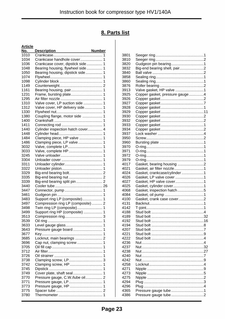
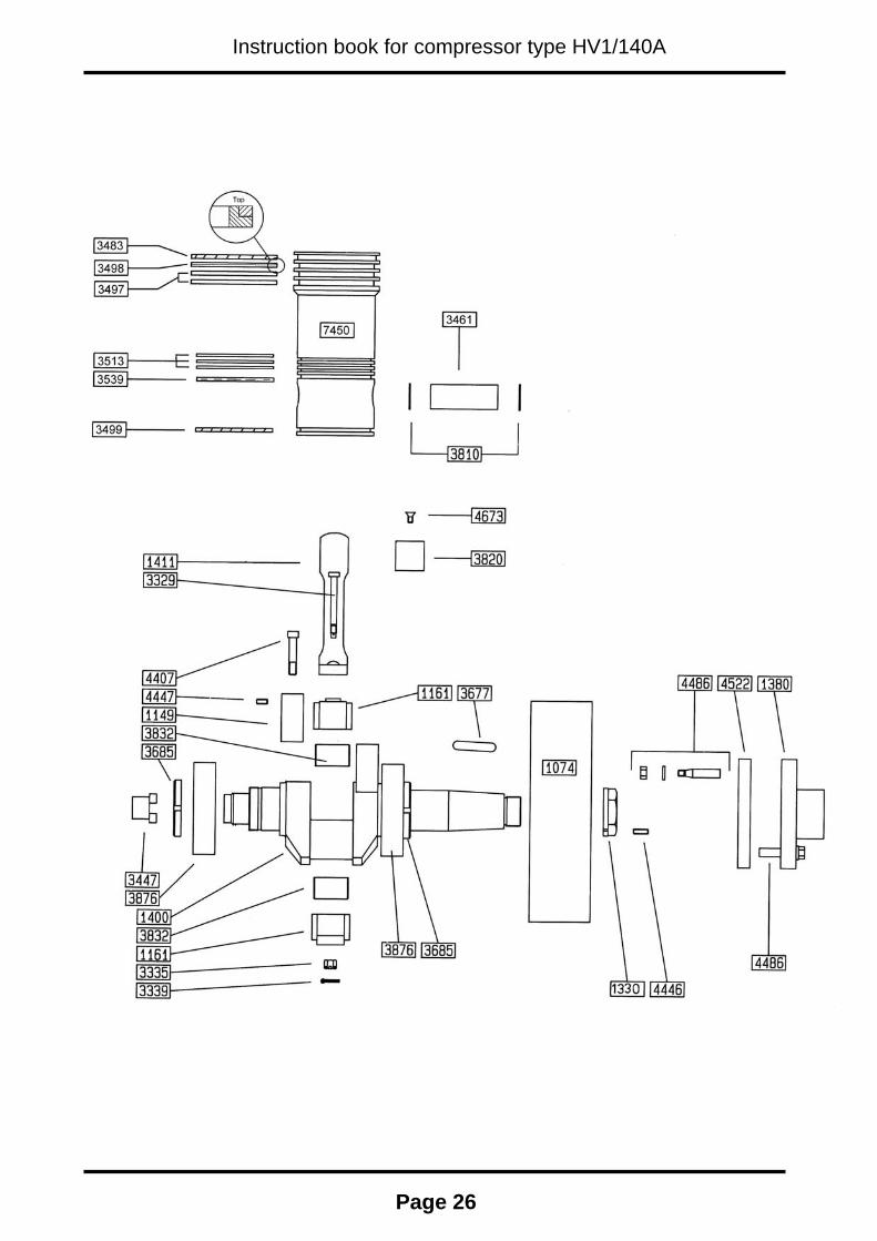
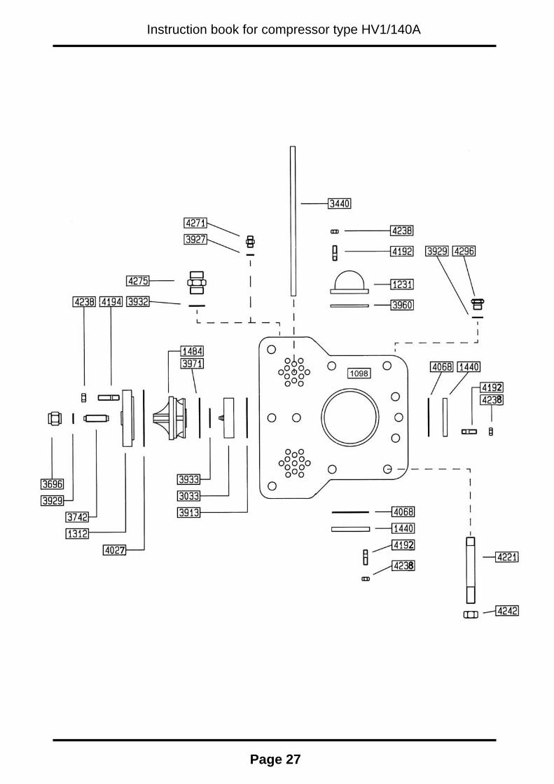
Article No. Description Number 1010 Crankcase............................................... 1 1034 Crankcase handhole cover..................... 1 1036 Crankcase cover, dipstick side ............... 1 1048 Bearing housing, flywheel side ............... 1 1050 Bearing housing, dipstick side ................ 1 1074 Flywheel.................................................. 1 1098 Cylinder block ......................................... 1 1149 Counterweight......................................... 2 1161 Bearing housing, pair.............................. 1 1231 Frame, bursting plate.............................. 1 1295 Air filter nozzle ........................................ 1 1310 Valve cover, LP suction side .................. 1 1312 Valve cover, HP delivery side................. 1 1330 Flywheel nut............................................ 1 1380 Coupling flange, motor side ................... 1 1400 Crankshaft .............................................. 1 1411 Connecting rod ....................................... 1 1440 Cylinder inspection hatch cover.............. 4 1448 Cylinder head.......................................... 1 1484 Clamping piece, HP valve ...................... 1 1486 Clamping piece, LP valve ....................... 1 3032 Valve, complete LP................................. 1 3033 Valve, complete HP ................................ 1 3245 Valve unloader........................................ 1 3304 Unloader cover ....................................... 1 3311 Unloader cylinder.................................... 1 3322 Unloader piston....................................... 1 3329 Big-end bearing bolt................................ 2 3335 Big-end bearing nut ................................ 2 3339 Big-end bearing split pin ......................... 2 3440 Cooler tube ............................................. 26 3447 Connector, pump .................................... 1 3461 Gudgeon pin ........................................... 1 3483 Support ring LP (composite)................... 1 3497 Compression ring LP (composite) .......... 2 3498 Twin ring LP (composite)........................ 1 3499 Support ring HP (composite) .................. 1 3513 Compression ring.................................... 3 3539 Oil ring .................................................... 1 3633 Level gauge glass................................... 1 3643 Pressure gauge board ............................ 1 3677 Key.......................................................... 1 3685 Locknut, main bearings .......................... 2 3696 Cap nut, clamping screw ........................ 1 3705 Oil fill cap ................................................ 1 3712 Air filter.................................................... 1 3726 Oil strainer .............................................. 1 3738 Clamping screw, LP................................ 3 3742 Clamping screw, HP ............................... 1 3745 Dipstick ................................................... 1 3749 Cover plate, shaft seal............................ 1 3770 Pressure gauge, C.W./lube oil................ 2 3771 Pressure gauge, LP................................ 1 3773 Pressure gauge, HP ............................... 1 3775 Spacer tube ............................................ 2 3780 Thermometer .......................................... 1
3801 Seeger ring..............................................1 3810 Seeger ring..............................................2 3820 Gudgeon pin bearing...............................1 3832 Big-end bearing shell, pair.......................2 3840 Ball valve .................................................2 3858 Sealing ring..............................................1 3860 Sealing ring..............................................1 3876 Roller bearing ..........................................2 3913 Valve gasket, HP valve ...........................1 3925 Copper gasket, pressure gauge..............4 3926 Copper gasket .........................................2 3927 Copper gasket .........................................7 3928 Copper gasket .........................................1 3929 Copper gasket .........................................11 3930 Copper gasket .........................................2 3932 Copper gasket .........................................2 3933 Copper gasket .........................................1 3934 Copper gasket .........................................2 3937 Lock washer ............................................4 3950 Screw.......................................................2 3960 Bursting plate ..........................................1 3970 O-ring.......................................................1 3971 O-ring.......................................................1 3972 O-ring.......................................................1 3979 O-ring.......................................................1 4017 Gasket, bearing housing .........................2 4021 Gasket, air filter nozzle............................1 4024 Gasket, crankcase/cylinder .....................1 4026 Gasket, LP valve cover ...........................1 4027 Gasket, HP valve cover...........................1 4025 Gasket, cylinder cover.............................1 4068 Gasket, inspection hatch .........................5 4084 Gasket, oil pump .....................................1 4100 Gasket, crank case cover........................2 4131 Backnut....................................................1 4142 T-joint.......................................................1 4188 Stud bolt ..................................................4 4189 Stud bolt ..................................................32 4192 Stud bolt ..................................................16 4194 Stud bolt ..................................................8 4207 Stud bolt ..................................................7 4221 Stud bolt ..................................................9 4222 Stud bolt ..................................................4 4236 Nut ...........................................................4 4237 Nut ...........................................................32 4238 Nut ...........................................................27 4240 Nut ...........................................................7 4242 Nut ...........................................................9 4258 Locknut ....................................................4 4271 Nipple ......................................................9 4273 Nipple ......................................................5 4275 Nipple ......................................................2 4294 Plug .........................................................3 4296 Plug .........................................................4 4365 Pressure gauge tube ...............................1 4386 Pressure gauge tube ...............................2
Page 23
Instruction book for compressor type HV1/140A
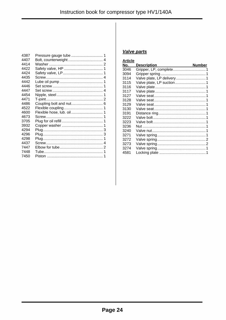
4387 Pressure gauge tube .............................. 1 4407 Bolt, counterweight ................................. 4 4414 Washer ................................................... 2 4422 Safety valve, HP ..................................... 1 4424 Safety valve, LP...................................... 1 4435 Screw...................................................... 4 4442 Lube oil pump ......................................... 1 4446 Set screw ................................................ 1 4447 Set screw ................................................ 4 4454 Nipple, steel ............................................ 1 4471 T-joint...................................................... 2 4486 Coupling bolt and nut.............................. 6 4522 Flexible coupling..................................... 1 4600 Flexible hose, lub. oil .............................. 1 4673 Screw...................................................... 1 3705 Plug for oil refill ....................................... 1 3932 Copper washer ....................................... 1 4294 Plug......................................................... 3 4296 Plug......................................................... 3 4298 Plug......................................................... 1 4437 Screw...................................................... 4 7447 Elbow for tube......................................... 2 7448 Tube........................................................ 1 7450 Piston ..................................................... 1
Valve parts Article No. Description Number 3046 Gripper, LP, complete...............................1 3094 Gripper spring...........................................1 3114 Valve plate, LP delivery ............................1 3115 Valve plate, LP suction .............................1 3116 Valve plate................................................1 3117 Valve plate................................................1 3127 Valve seat .................................................1 3128 Valve seat .................................................1 3129 Valve seat .................................................1 3130 Valve seat .................................................1 3191 Distance ring.............................................1 3222 Valve bolt ..................................................1 3223 Valve bolt ..................................................1 3236 Nut ............................................................1 3240 Valve nut...................................................1 3271 Valve spring..............................................1 3272 Valve spring..............................................2 3273 Valve spring..............................................2 3274 Valve spring..............................................1 4581 Locking plate ............................................1
Page 24

Instruction book for compressor type HV1/140A
Page 25
Instruction book for compressor type HV1/140A
Page 26
Instruction book for compressor type HV1/140A
Page 27

Instruction book for compressor type HV1/140A
Page 28

Instruction book for compressor type HV1/140A Instruction book for compressor type HV1/140A
Page 29
Page 29
Sole suppliers of genuine spare parts: Sperre Asia PTE Ltd
63 Hillview Avenue #09-13 Lam Soon Industrial Building
Singapore 669569 Tel +65 6763 6300 Fax + 65 6763 1811
Sperre Industri AS N-6057 Ellingsøy
Norway Tel +47 70 16 11 00 Fax + 47 70 16 11 10 [email protected]
Sperre Rotterdam BV Glasblazerstraat 12B
NL-2984 BL Ridderkerk The Netherlands
Tel +31 180 463 299 Fax + 31 180 463 264 [email protected]
www.sperre.com